

Page 1
INSTRUCTIONS AND ILLUSTRATED PARTS MANUAL
INSTRUCCIONES Y CATALOGO DE PARTES Y PIEZAS
ANTAEUS Y HERAKLES COMBINADA, MAQUINA DE DOS AGUJAS,
CUATRO HILOS, PUNTADA DE SEGURIDAD, PARA COSER SIN
PELIGRO DE DESPLAZAMIENTO PIEZAS DE SACOS DE MATERIAL
PESADO / FUERTE
MANUAL NO. / CATALOGO Nº G230A
FOR STYLES / PARA ESTILOS
81300A, AJ, A1, A1H, A2 - 81300B, B1H, B2
Page 2

INSTRUCTIONS AND ILLUSTRATED PARTS LIST
MANUAL NO. G230A
FOR 81300 SERIES MACHINES
INSTRUCCIONES Y LISTA DE PARTES
CATALOGO NO. G230A
ILUSTRADAS MODELOS SERIE 81300
Third Edition Copyright 2002
by
Union Special GmbH Rights Reserved in All
Countries
Printed in Germany
PREFACE
This catalog has been prepared to guide you while
operating 81300 series machines and arranged to simplify
ordering spare parts.
This catalog explains in detail the proper settings for
operation of the machines. Illustrations are used to show
the adjustments and reference letters are used to point
out specific items discussed.
Careful attention to the instructions and cautions for
operating and adjusting these machines will enable you
to maintain the superior performance and reliability
designed and built into every Union Special bag sewing
machine.
Adjustments and cautions are presented in sequence so
that a logical progression is accomplished. Some
adjustments performed out of sequence may have an
adverse effect on the function of the other related parts.
Tercera Edición © 2002
Union Special GmbH
Derechos Reservados
en todos los paises del mundo
Impreso en Alemania
INTRODUCCION
Este manual fue preparado para guiar al usuario en la
operación de máquinas de la serie 81300 y ayudar a
simplificar la elaboración de los pedidos de repuestos.
Este manual explica detalladamente los ajustes para la
operación de la máquina. Las ilustraciones sirven para
demostrar los ajustes y las letras en referencia indican
los puntos específicos discutidos.
Una cuidadosa atención a las instrucciones y las precauciones operando y ajustando estas máquinas le va a
permitir mantener el mejor funcionamiento y la confiabilidad que caracteriza las máquinas cosedoras de sacos
de Union Special.
Los ajustes y precauciones son presentados en secuencia para que se consiga una progresión lógica. La ejecución de algunos ajustes fuera de la secuencia puede
causar un efecto adverso para el funcionamiento de otras
partes relacionadas.
This manual has been comprised on the basis of available
information. Changes in design and / or improvements
may incorporate a slight modification of configuration in
illustrations or cautions.
On the following pages will be found illustrations and
terminology used in describing the instructions and the
parts for your machine.
In addition to the instructions and to the mandatory rules
and regulations for accident prevention and environmental
protection in the country and place of use of the machine
/ unit, the generally recognized technical rules for safe
and proper working must also be observed.
The instructions are to be supplemented by the respective
national rules and regulations for accident prevention and
environmental protection.
Este manual se comprende a base de la información
actual. Cambios en diseño y/o mejoras pueden significar
leves modificaciones de la configuración de las ilustraciones o precauciones.
En las paginas siguientes se encuentran ilustraciones y
terminologías usadas en la descripción de las instrucciones y las piezas de la máquina.
Adicionalmente a las instrucciones, las reglas y regulaciones obligatorias para prevenir accidentes y la protección ambiental del país y lugar donde se encuentra la
máquina/unidad, hay que considerar las reglas técnicas
para un trabajo seguro y adecuado.
Las instrucciones hay que complementarlas con las
respectivas reglas y regulaciones nacionales contra accidentes y protección del ambiente.
2
Page 3

TABLE OF CONTENTS
INDICE
SAFETY RULES
REGLAS DE SEGURIDAD
IDENTIFICATION OF MACHINES
IDENTIFICACION DE LAS MAQUINAS
APPLICATION OF THIS INSTRUCTION MANUAL
APLICACION DE ESTE MANUAL DE INSTRUCCIONES
ORDERING WEAR AND SPARE PARTS
INSTRUCCIONES PARA LOS PEDIDOS DE REPUESTOS
STYLES OF MACHINES
ESTILOS DE MAQUINAS
INSTALLATION
INSTALACION
LUBRICATING
LUBRICACION
NEEDLES
AGUJAS
THREADING DIAGRAM
DIAGRAMA DE ENHEBRADO
OPERATING INSTRUCTIONS
INSTRUCCIONES DE OPERACION
MAINTENANCE
MANTENIMIENTO
INSTRUCTIONS FOR MECHANICS
INSTRUCCIONES PARA LOS MECANICOS
VIEWS AND DESCRIPTION OF PARTS
DIBUJOS Y DESCRIPCION DE LOS REPUESTOS
BUSHINGS, SIGHT FEED OILER, SPRING VALVE OILER
BOCINAS Y PARTES DE LUBRICACION
CLOTH PLATE, BASE PLATE, GUARDS AND MISCELLANEOUS COVERS
TAPA Y BASE DE LA MAQUINA, GUARDAS Y OTRAS TAPAS
THREAD TENSIONS AND THREAD GUIDE PARTS
TENSIONES DE LOS HILOS Y PARTES DE LOS GUIA HILOS
NEEDLE BAR, NEEDLE LEVER, CRANK SHAFT, HANDWHEEL
BARRAS DE LA AGUJA, LEVANTADOR DE AGUJA, EJE PRINCIPAL, VOLANTE
LOOPER DRIVE MECHANISM
MECANISMO DE OPERACION DEL LOOPER
LOWER AND UPPER FEED DRIVE MECHANISM
MECANISMOS DEL TRANSPORTE INFERIOR Y SUPERIOR
PRESSER BARS, LEAF SPRINGS AND PRESSER FOOT LIFTER LEVER FOR 81300A, AJ, A1, B
BARRAS, MUELLES PARA LAS BARRAS Y LEVANTADOR DEL PIE PRENSATELAS PARA 81300A, AJ, A1, B
ELECTRO-PNEUMATIC PARTS KIT FOR UPPER FEED PRESSURE AND LIFTER FOR 81300A1H, A2, B1H, B2
PIEZAS SISTEMA ELECTRONEUMATICO PARA PRESION DEL PIE SUPERIOR Y LEVANTAR PIE PRENSATELAS
PARA 81300A1H, A2, B1H, B2
CONTROL FOR ELECTRO-PNEUMATIC HOT THREAD CHAIN CUTTER FOR 81300A1H, B1H
CONTROL SISTEMA ELECTRONEUMATICO CORTADOR CALIENTE DE CADENETA PARA 81300A1H, B1H
ELECTRO-PNEUMATIC HOT THREAD CHAIN CUTTER FOR 81300A1H, B1H
SISTEMA ELECTRONEUMATICO CORTADOR CALIENTE DE CADENETA PARA 81300A1H, B1H
SEWING PARTS - PIEZAS DE FORMACION DE COSTURA
ACCESSORIES - ACCESORIOS
NUMERICAL INDEX OF PARTS - INDICE NUMERICO DE PARTES
3
Page
Página
4 - 5
6
6
6
7
8 - 9
10 - 11
11
12
13
13
14-22
23
24 - 25
26 - 27
28 - 29
30 - 31
32 - 35
36 - 37
38 - 39
40 - 41
42 - 45
46 - 47
48 - 49
50 -51
52 - 53
Page 4
SAFETY RULES
REGLAS DE SEGURIDAD
1. Before putting the machines described in this manual
into service, carefully read the instructions. The starting
of each machine is only permitted after taking notice of
the instructions and by qualified operators.
IMPORTANT! Before putting the machine into service,
also read the safety rules and instructions from the
motor supplier.
2. Observe the national safety rules valid for your country.
3. The sewing machines described in this instruction manual
are prohibited from being put into service until it has
been ascertained that the sewing units which these
sewing machines will be built into, have conformed with
the provisions of EC Machinery Directive 98/37/EC,
Annex II B.
Each machine is only allowed to be used as foreseen.
The foreseen use of the particular machine is described
in paragraph "STYLES OF MACHINES" of this instruction
manual. Another use, going beyond the description, is
not as foreseen.
4. All safety devices must be in position when the machine
is ready for work or in operation. Operation of the
machine without the appertaining safety devices is
prohibited.
1. Antes de poner en marcha las máquinas descritas en
este manual, hay que leer cuidadosamente las instrucciones. El arranque de cada máquina solamente
se permite después de haber leído las instrucciones y
por personal calificado.
IMPORTANTE! Antes de poner la máquina a operar,
también hay que leer las reglas de seguridad y las
instrucciones del fabricante del motor.
2. Observe las reglas nacionales de seguridad que
rigen para su país.
3. No se puede poner en marcha la máquina descrita en
este manual hasta que se confirme que la unidad de
coser esta conforme con el reglamento del Directivo
de las Máquinas de la Comunidad Europea 98/37/EC,
Anexo II B.
La máquina solamente se puede utilizar para su uso
previsto. El uso previsto esta descrito en el capitulo
ESTILO DE MAQUINAS de este manual de instrucciones. Otro uso, diferente de la descripción, no está
previsto.
4. Todos los dispositivos de seguridad tienen que estar
en su sitio cuando la máquina esté lista para trabajar
u operando. La operación de la máquina sin los
dispositivos de seguridad esta prohibida.
5. Wear safety glasses.
6. In case of machine conversions and changes all valid
safety rules must be considered. Conversions and
changes are made at your own risk.
7. The warning hints in the instructions are marked with
one of these two symbols.
8. When doing the following the machine has to be
disconnected from the power supply by turning off
the main switch or by pulling out the main plug.
8.1 When threading needle(s), looper,
spreader etc.
8.2 When replacing any parts such as
needle, presser foot, throat plate,
looper, spreader, feed dog, needle guard,
folder, fabric guide etc.
8.3 When leaving the workplace and when
the work place is unattended.
8.4 When doing maintenance work.
8.5 When using clutch motors with or without
actuation lock, wait until motor is stopped
totally.
5. Utilice lentes de seguridad.
6. En el caso de una modificación de la máquina hay que
tomar en cuenta las reglas de seguridad. Modificaciones y cambios corren por su riesgo.
7. Las advertencias en el manual de instrucciones están
marcadas con las siguientes señales de aviso:
8. Para las siguientes maniobras hay que desconectar
la máquina del suministro eléctrico desconectando el
enchufe principal:
8.1 Enhebrando agujas, loopers y spreaders.
8.2 Reemplazando piezas como agujas, pie prensa
tela, plancha de aguja, looper, spreader, dientes
de arrastre, guarda aguja, dobladilladores, guía
tela, cuchillas, etc.
8.3 Cuando salga de su puesto de trabajo y no se
encuentre alguien para atender la máquina.
8.4 Durante trabajos de mantenimiento.
8.5 Utilizando motores de embrague sin freno, tie-
ne que esperar que el motor pare completamen-
te.
4
Page 5

9. Maintenance, repair and conversion work (see item 8)
must be done only by trained technicians or special
skilled personnel under condsideration of the
instructions.
9. Mantenimiento, reparaciones y trabajos de conversión (véase No. 8) solamente pueden ser efectuados por técnicos entrenados o personal especializado bajo consideración de las instrucciones.
Only genuine spare parts approved by UNION
SPECIAL have to be used for repairs. These parts are
designed specifically for your machine and
manufactured with utmost precision to assure long
lasting service.
10. Any work on the electrical equipment must be done by
an electrician or under direction and supervision of
special skilled personnel.
11. Work on parts and equipment under electrical power
is not permitted. Permissible exceptions are described
in the applicable section of standard sheet EN 50 110
/ VDE 0105.
12. Before doing maintenance and repair work on the
pneumatic equipment, the machine has to be
disconnected from the compressed air supply. In
case of existing residual air pressure after
disconnecting from compressed air supply (e.g.
pneumatic equipment with air tank), the pressure has
to be removed by bleeding. Exceptions are only
allowed for adjusting work and function checks done
by special skilled personnel.
Solamente repuestos originales y aprobados por
Union Special pueden ser utilizados para reparaciones. Estos repuestos han sido diseñados específicamente para estas máquinas, con precisión y
para asegurar su máxima vida útil.
10. Cualquier trabajo con el equipo eléctrico tiene que
ser ejecutado por un electricista o bajo la supervisión de personal especialmente entrenado.
11. No está permitido trabajar en piezas y equipos con
la electricidad conectada. Excepciones permitidas
están descritas en EN 50110 / VDE 0105.
12. Antes de hacer mantenimiento o reparaciones del
equipo neumático, hay que desconectar la máquina de la alimentación del aire comprimido. En el
caso que exista una presión de aire residual
después de desconectar la máquina (por ejemplo
equipos con tanques de aire), la presión tiene que
ser eliminada abriendo las válvulas. Excepciones
están solamente permitidas para trabajos de
ajuste y revisión de funciones por personal especialmente entrenado.
5
Page 6
IDENTIFICATION OF MACHINES
IDENTIFICACION DE LAS MAQUINAS
Each UNION SPECIAL 81300 series machine is identified
by a style number, which is stamped on the style plate
affixed to the right front of machine. Serial number is
stamped into bed casting at the right front base of
machine.
APPLICATION OF THIS INSTRUCTION MANUAL
NOTE: Instructions stating direction or location, such as
right, left, front or rear of machine, are given relative to operator’s position at the machine, unless
otherwise noted.
The handwheel pulley rotates clockwise, in
operating direction. when viewed from the right
end of machine.
CAUTION! Before putting into service check the di-
rection of rotation. Breakage may occur
when the direction of rotation is wrong.
ORDERING WEAR AND SPARE PARTS
To simplify ordering wear and spare parts exploded views
of various sections of the mechanism are shown, so that
the parts may be seen in their actual position in the
machine. On the page opposite the illustration will be found
a listing of the parts with their part numbers, descriptions
and the number of pieces required in the particular view
being shown.
Cada máquina UNION SPECIAL 81300 está identificada por
un número de estilo, el cual está estampado en la placa fijada
a la máquina. El número de serial está troquelado en la
carcasa de la máquina.
APLICACION DE ESTE MANUAL DE INSTRUCCIONES
NOTA: Instrucciones que se refieren a direcciones y
posiciones como derecho, izquierdo, adelante o atrás
se entienden desde el punto de vista de un operador
sentado enfrente de la máquina, si no está notificado
de una manera diferente.
El manubrio del volante gira en sentido del reloj, en
su dirección de operación, cuando es visto desde la
parte derecha del final de la máquina.
PRECAUCION: Revise antes de poner la máquina en
marcha el sentido de la rotación. El sentido
de rotación equivocado puede causar roturas.
PEDIDO DE PIEZAS DE REPUESTOS
Este catálogo fue diseñado para facilitar los pedidos de los
repuestos. Los dibujos de grupos específicos del mecanismo
demuestran la posición de las piezas en la máquina de coser.
En la página en frente de la página de la ilustración se
encuentra un listado de las piezas con su número de repuesto,
descripción y la cantidad requerida para la sección indicada.
Numbers in the first column are reference numbers only,
and merely indicate the position of that part in the
illustration. Reference numbers should never be used in
ordering parts. Always use the part number listed in the
second column.
Component parts of sub-assemblies which can be
furnished for repairs are indicated by identing their
description under the description of the main subassembly.
At the back of the catalog will be found a numerical index
of all parts shown in this catalog. This will faciliate locating
the illustration and description when only the part number
is known.
IMPORTANT! ON ALL ORDERS, PLEASE INCLUDE
PART NUMBER, PART NAME, QUANTITY REQUIRED
AND STYLE OF MACHINE FOR WHICH PART IS
ORDERED.
Los números de la primera columna son números de referencia e indican donde se encuentra la piezas en la ilustración.
Los números de referencia no se deben utilizar en sus pedidos
de repuestos. Utilice siempre el número de repuesto de la
segunda columna.
Componentes de piezas compuestas que se pueden suministrar como repuestos se encuentran diferenciados en tal forma
que las descripciones están desplazadas hacia la derecha
referente a la descripción de la pieza compuesta.
Al final de este catálogo se encuentra un listado de los
números de partes de todos los repuestos que están descritos
en el mismo. Esto facilita encontrar la ilustración y descripción
de la pieza en el caso que solamente se conozca el número del
repuesto.
NOTA! FAVOR INDICAR EN TODOS LOS PEDIDOS EL
NUMERO, LA DESCRIPCION DEL REPUESTO Y EL MODELO DE LA MAQUINA.
6
Page 7

STYLES OF MACHINES
ESTILOS DE MAQUINAS
81300A: Combined ANT AEUS / HERAKLES two needle four
thread safety stitch machine. Lower and upper feed. Adjusted
for polypropylene sewing threads.
Manual lubrication.
For matched seaming of very heavy bag fabrics made of
jute, burlap or woven polypropylene with a 10 mm (3/8")
wide overedge stitch on the fabric edge and in a distance of
5 mm (13 gauge) to this with an additional double locked
stitch.
Seam specification (401.502) SSa-2.
Needle distance 5 mm (13 gauge).
Seam width over all 15 mm (19/32").
Standard needle 9853GA430/172.
Stitch range 6 to 13 mm ( 2 to 4 SPI), standard setting 10
mm (2 1/2").
Working dia. of handwheel pulley 150 mm (5 29/32").
Capacity below the presser foot up to 19 mm (3/4").
Speed up to 1400 stitches per minute depending on the
operation.
Recommended operating speed 1200 stitches per minute.
Equivalent continuous A-weighted sound pressure level on
work stations at recommended operating speed: 84 dB(A)
according to DIN 45635-48 / ISO 10 821.
Weight net: 40 kg
81300AJ: Same as 81300A, but adjusted for jute threads.
81300A1: Same as 81300A, but with feed dog A10482A
and throat plate A10481AC with opening 6 mm for filler cord
from below and guide for filler cord from the top for sealing
the needle punctures of the left needle.
81300A1H: Same as 81300A, but with built-in electropneumatically operated hot thread chain cutter. Electropneumatically operated presser foot and upper feed dog
lifter.
Pneumatic presser foot spring.
Guides for filler cord from the top and / or from below for
sealing the needle punctures of the left needle.
81300A2: Same as 81300A1H, but without any thread chain
cutter.
81300B: Same as 81300A, but oberedge seam width 19
mm = seam width overall 24 mm.
81300B1H: Same as 81300A1H, but overedge seam width
19 mm = seam width overall 24 mm.
81300B2: Same as 81300A1H, but overedge seam width
19 mm = seam width overall 24 mm and without any thread
chain cutter.
Use UNION SPECIAL sewing tables for the described
sewing machines. UNION SPECIAL sewing tables
complete the particular sewing machine to a sewing unit
and guarantee safe operation as well as the indicated
data of the sound pressure level generated by the sewing
unit.
81300A: Combinación de ANTAEUS / HERAKLES, máquina
de dos agujas, cuatro hilos, puntada de seguridad. Alimentación superior e inferior. Especial para trabajos con hilos de
polipropileno. Lubricación manual.
Para coser sin peligro de desplazamiento los pliegos de los
sacos contenedores de material muy pesado, como yute, arpillera o polipropileno tejido con una puntada de 10 mm de
ancho y en una distancia de 5 mm, con puntada doble de
seguridad.
Especificación de costura (401.502) SSa-2.
Distancia entre agujas 5 mm.
Ancho máximo de costura 15 mm.
Aguja normal 9853GA430/172.
Rango de puntada 6 - 13 mm, ajuste normal 10 mm.
Diámetro efectivo del volante 150 mm.
Capacidad debajo del pie prensatelas hasta 19 mm.
Velocidad hasta 1400 punt adas / min., dependiendo de la operación.
Velocidad de operación recomendada 1200 puntadas / min.
Nivel de ruido de la unidad referente a al puesto de trabajo con
la velocidad de operación recomendada: 84 dB(A) de acuerdo
con normas DIN 45635-48 / ISO 10 821.
Peso neto: 40 kg.
81300AJ: Igual a la 81300A, pero ajustada para hilos de yute.
81300A1:
plancha de aguja A10481AC con apertura de 6 mm para cordón de relleno que viene desde abajo y guía para cordón de
relleno que viene desde arriba para sellar las perforaciones
de la aguja izquierda.
81300A1H: Igual a la 81300A, pero con cortador electroneumático caliente de cadeneta y pie prensatelas y levantador del
diente superior activados electroneumáticamente.
Pie prensatelas con presión neumática por pistón.
La máquina esta equipada con una guía superior e inferior de
los cordeles para sellar las perforaciones de las agujas desde
arriba y/o desde abajo de la aguja izquierda.
81300A2: Igual a la 81300A1H, pero sin cortador caliente de
cadeneta.
81300B: Igual a la 81300A, pero con ancho de costura de 19
mm = ancho de costura total 24 mm.
81300B1H: Igual a la 81300A1H, pero con ancho de costura
de 19 mm = ancho de costura total 24 mm.
81300B2: Igual a la 81300A1H, pero con ancho de costura de
19 mm = ancho de costura total 24 mm y sin ningún cortador
de cadeneta.
Utilice montajes de UNION SPECIAL para las máquinas descritas. Mesas y pedestales de UNION SPECIAL complementan las máquinas de coser a una unidad de coser y garantizan una operación segura y los niveles de ruido.
Igual a la 81300A, pero con transporte A10482A y
7
Page 8
INSTALLATION AUFSTELLUNG
8
Page 9

INSTALLATION (continued)
INSTALACION (Continuación)
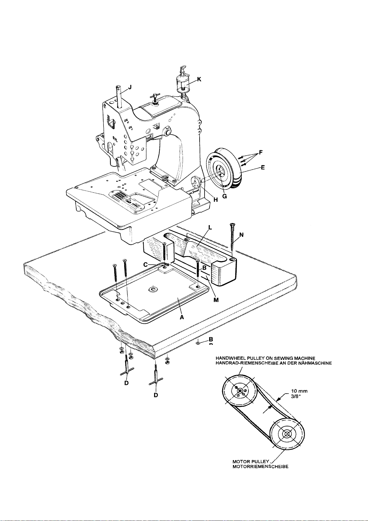
1. Unpack the sewing machine and the accessories.
2. Mount the base plate (A) with four screws, nuts
and washers (B) in the provided holes on the table
board.
3. Place the sewing machine on the base plate so
that the roll pin (C) in the base plate engages with
the right rear hole in the machine base.
4. Fasten the sewing machine with the two T-screws
(D) on the base plate.
5. Place the V-belt, supplied with the sewing table,
on the handwheel pulley .
6. Assemble the handwheel pulley (E) with three
countersunk screws (F) to the sewing machine. Pin
(G) must engage with the hole in hub (H).
7. Screw in needle bar guard (J).
8. Screw in sight feed oiler (K).
9. Align the handwheel belt guard (L) with the V-belt
slot (M) in the table board and with the handwheel
pulley and fasten it with two wood screws (N) on
the table board.
1. Desempaque la máquina y los accesorios.
2. Monte la placa de base (A, Fig. 1) con los 4 tornillos,
las tuercas y las arandelas (B) en los huecos ya listos en la tabla de la mesa.
3. Coloque la máquina sobre la base, de manera que el
pasador de regulación (C) en la placa base, encaje
en el hueco derecho trasero de la base de la máquina.
4. Asegure la máquina de coser con los 2 tornillos T (D)
en la placa de base.
5. Coloque la correa en forma de V, en la rueda del volante.
6. Monte el volante (E) con los 3 tornillos remache (F) a
la máquina de coser. El pasador (G) debe encajar en
el hueco de la parte central del volante (H).
7. Atornille el protector de la barra de aguja (J).
8. Apriete la aceitera (K).
9. Alinee el guarda correa del volante (L) con la perforación para la correa en la mesa (M) y con la rueda del
volante y sujételo con los 2 tornillos para madera (N)
a la mesa.
10. Dismount motor belt guard. Place the V-belt around
the motor pulley and slue the motor to tense the
belt. The tension on the V -belt is correct, when with
moderate finger pressure it will deflect approx.10
mm (3/8") midway between handwheel pulley on
the sewing machine and motor pulley.
Remount motor belt guard.
11. Hook the lifter chain to the lifter lever of the sewing
machine and to the small treadle on the sewing
table.
12. Assemble the thread stand and mount the thread
stand base with four wood screws on the right rear
corner of the table board.
13. Before being put into service note the specified
service voltage and frequency of the motor. Check
if the mains voltage and frequency at site
correspond with the factory specified service voltage
and frequency.
14. Check the direction of rotation. The handwheel
pulley must rotate clockwise (to the right), when
viewed from the right end of the machine.
Switch on the motor. Only shortly and very slightly
depress the motor treadle and check the direction
of rotation. Immediately release the treadle. Switch
off and wait until the motor has stopped.
10. Desmonte el guarda correa del motor. Coloque la correa en V alrededor del volante y ajuste el motor para
tensar la correa. La tensión del la correa en V será la
correcta cuando ejerciendo presión moderada con el
dedo ceda en aprox. 10mm (3/8 pulgada) en la mitad
entre la rueda del volante en la máquina de coser y la
rueda del motor (Ver Fig. 2).
Coloque nuevamente el guarda correa del motor.
11. Enganche la cadena a la palanca levantadora de la
máquina de coser y al pequeño pedal en la mesa de la
máquina de coser.
12. Asegure la base del porta conos con tres tornillos al
lado derecho de la mesa de la máquina de coser y
monte el porta conos.
13. Antes de comenzar a utilizar la máquina, verifique que
el voltaje y la frecuencia del motor coinciden con la
instalada en el lugar donde operará la máquina.
14. Verifique la dirección de rotación. El volante debe girar en dirección del reloj (a la derecha), cuando es
visto desde la parte derecha de la máquina.
Encienda el motor. Presione ligeramente el pedal y
chequee la dirección de rotación. Suéltelo inmediatamente. Apague el motor y espere hast a que se detenga totalmente.
CAUTION! In case the direction of rotation has to
be changed, the reversing of the
polarity is only allowed to be done by a
skilled electrician.
PRECAUCION! En el caso que la dirección de rotación
deba ser cambiada, la reversión de la polaridad debe ser realizada por un electricista calificado.
9
Page 10
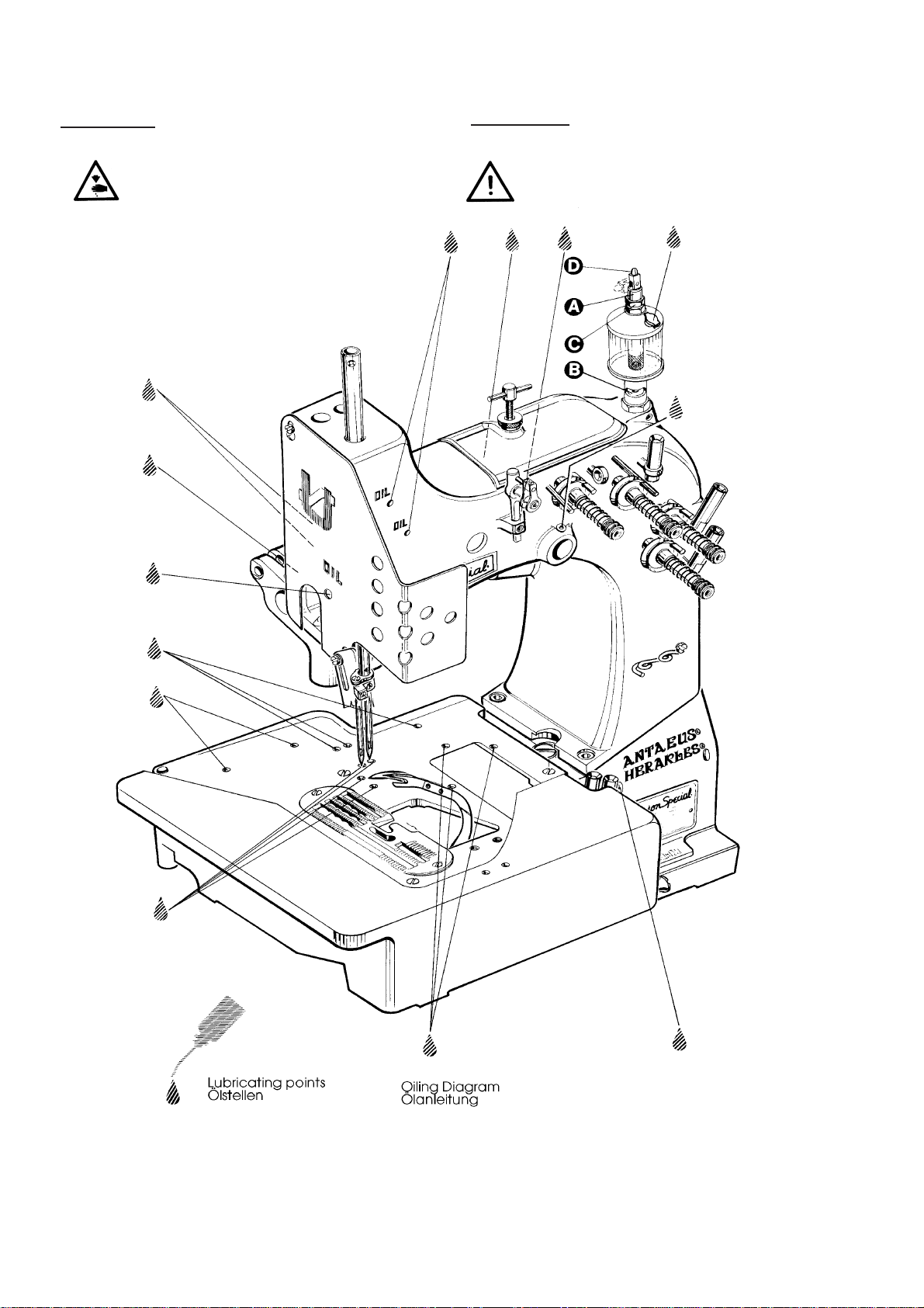
LUBRICATING
LUBRICACION
CAUTION!
Turn off main power switch before
lubricating! When using clutch motors with
or without actuation lock wait until motor
has completely stopped.
PRECAUCION!
Antes de lubricar, apague el interruptor
principal. Con un motor de embrague sin
freno espere hasta que el motor se
detenga completamente!
Fig. 1
10
Page 11

LUBRICATING (continued)
LUBRICACION (Continuación)
PREPARING FOR OPERATION
Before operating a new machine for the first time, the
sight feed oiler has to be adjusted. All lubricating points,
indicated on the oiling diagram (Fig. 1) have to be oiled.
For adjusting fill the sight feed oiler halfway with oil and
turn the metering pin (A, Fig. 1) a little bit out and then
turn it in, until there will flow two to three drops of oil per
minute. This can be checked on the sight glass (B). Secure
the setting of the metering pin with lock nut (C). Fill the
oiler.
Repeat the oiling of a new machine after 10 minutes of
operation!
When the machine is out of operation, the oil flow can be
stopped by tilting lever (D) on the sight feed oiler.
IMPORTANT!The oil flow has to be switched on again
before operating the machine.
For lubrication we recommend "Mobil Oil DTE Medium"
or equivalent, which can be purchased from UNION
SPECIAL in 1/2 liter containers under part number
G28604L or in 5 liter containers under part number
G28604L5.
NEEDLES
Each needle has both a type and a size number. The type
number denotes the kind of shank, point, length, groove,
finish and other details. The metric size number , st amped
on the needle shank, denotes largest diameter of blade,
measured in hundreds of a mm midway between shank
and eye. Collectively , the type and size number represent
the complete symbol, which is given on the label of all
needles packaged and sold by UNION SPECIAL.
INSTRUCCIONES DE OPERACION
Antes de poner en marcha una nueva máquina por la primera
vez, hay que fijar y ajustar el engrasador cuentagotas.
Lubrique todos los puntos indicados en el diagrama de lubricación (Fig. 1). Llene el engrasador cuentagotas hasta la mitad
con aceite y ajuste girando el pasador de la regulación (A, Fig.
1) en tal manera que suministre aproximadamente dos gotas
de aceite por minuto. Este ajuste se puede revisar a través del
vidrio (B). Asegure la posición del pasador de la regulación con
la contratuerca (C). Llene el engrasador cuentagotas con
aceite.
Para máquinas nuevas, repita la lubricación después de diez
minutos de operación.
Si la máquina no está operando se puede parar el flujo del
aceite doblando la palanca (D) del engrasador cuentagotas.
Nota: El flujo de aceite tiene que ser restablecido
de operar la máquina otra vez.
Para la lubricación recomendamos „Mobil Oil DTE Medium“ o
un aceite equivalente, que se puede pedir a UNION SPECIAL
en contenedores de ½ litro bajo el número de referencia
G28604L y en contenedores de 5 litros bajo el número de
referencia G28604L5.
AGUJAS
Cada aguja tiene un número de sistema y un número del
grosor. El número del sistema se refiere al tipo del cabo, la
punta, el largo, la ranura, acabado y otros detalles. El número
del grosor, troquelado en el cabo, indica el grosor máximo de
la caña, medido en la mitad de la distancia entre cabo y ojo de
la aguja. El número del sistema y del grosor dan la descripción
completa, que se encuentra en todos los empaques de agujas
vendidas por UNION SPECIAL.
antes
TYPE AND DESCRIPTION
9853GA Round shank with tapered flat, rounded square
point, single groove, spotted, chromium plated.
Sizes available: 300/120, 400/156, 430/172.
Standard needle for these machines is 9853GA430/172.
When changing the needle, make sure it is fully inserted
in the needle head with the fastening flat of the needle
shank facing the screw, before the screw is tightened.
NEEDLE ORDERING
When ordering needles please use the complete type and
size numbers as printed on the package to ensure prompt
and accurate processing of your order.
A complete order should read as follows:
100 needles, type 9853GA430/172.
TIPO Y DESCRIPCION
9853GA Cabo redondo con superficie plana para asentar la
aguja, punta cuadrada redondeada, ranura simple, rebajo,
cromada. Tamaños disponibles: 300/120, 430/172.
Aguja normal para estas máquinas es 9853GA430/172.
Al cambiar la aguja, asegúrese que esté totalmente inserta-
da en su lugar, con la superficie plana para asentar la aguja frente al tornillo, antes de apretarlo.
PEDIDO DE AGUJAS
Para garantizar un despacho correcto y rápido les sugerimos
enviarnos el empaque vacío de las agujas o una aguja de
muestra o indicar el sistema con el grosor. Utilice la descripción de la etiqueta en el empaque de la aguja.
Un pedido completo de agujas sería por ejemplo:
100 agujas, tipo 9853GA, Grosor 430/172.
11
Page 12
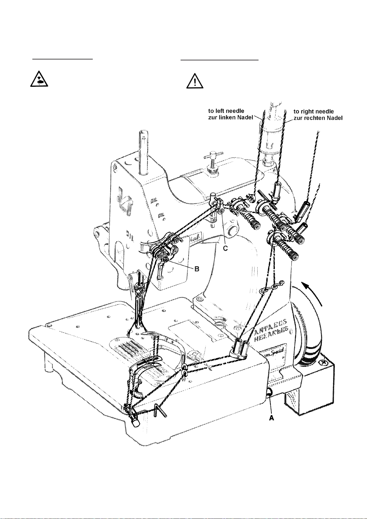
THREADING DIAGRAM
DIAGRAMA DE ENHEBRADO
CAUTION! Turn off main power switch before
threading! When using clutch motors with
or without actuation lock wait until the
motor has completely stopped!
PRECAUCION! Apague el motor principal antes de enhe-
brar!. Cuando utilice motor con clutch debe
esperar hasta que el mismo se detenga totalmente!.
Aguja izquierda Aguja derecha
Fig. 2
12
Page 13
OPERATING INSTRUCTIONS
INSTRUCCIONES DE OPERACION
THREADING
81300 series are threaded as shown in Fig. 2.
For threading the needle turn handwheel in operating
direction until the needle is in the upmost position.
For looper threading open the hinge plate by lifting locking
bolt knob (A, Fig. 2).
Reclose hinge plate after threading.
OPERATING
1. Switch on main power switch.
2. Without lifting the presser foot, place the fabric to be
sewn as close as possible in front of the needle and to
the right on the edge guide.
CAUTION! Remove the foot from the motor treadle, to
avoid inadvertently starting of the machine,
in case it is necessary to lift presser foot and
upper feed dog for aligning the fabric to be
sewn!
3. Depress the motor treadle. The machine sews.
Guide the fabric to be sewn.
CAUTION! Keep a security distance of approx. 100
mm (4") between hand and sewing needle
when guiding the fabric to be sewn!
ENHEBRADO
Las máquinas de la serie 81300 se enhebran como se muestra en la Fig. 2.
Para enhebrar la aguja gire el volante en dirección de operación hasta que la aguja alcance su posición mas alta.
Para enhebrar el looper, abra la tapa delantera levantando
el tornillo de la manivela (A, Fig. 2).
Cierre la tapa delantera otra vez.
OPERACION
1. Active el interruptor principal.
2. Ponga las telas lo más cercano posible delante de la
aguja y a la derecha a la guía tope, sin levantar el pie prensatela.
PRECAUCION!!
3. Pise el pedal de motor hacia adelante. La máquina cose.
Guíe las telas.
PRECAUCION! Mantenga una distancia de por lo menos
Quite el pie del pedal del motor para no
arrancar la máquina accidentalmente, si fuera necesario levante el pie prensatela y el transporte superior manualmente para guiar las
telas.
100 mm entre la aguja y la mano mientras
guíe las telas!
4. Release the motor treadle. The machine stops.
Cut the thread chain at the trailing edge of the fabric
and remove the fabric from the machine.
MAINTENANCE
CAUTION! Turn off main power switch before doing
maintenance works! When using clutch
motors with or without actuation lock wait
until the motor has stopped!
LUBRICATING AND CLEANING
The machines of class 81300 have to be cleaned and
lubricated twice a day before the morning and afternoon start
on the lubrication points indicated on the oiling diagram (Fig.
1, page 10). The sight feed oiler has to be kept filled and
should be ajdusted so, that it feeds two to three drops of oil
per minute. The oiler has to be refilled latest, when 2/3 of the
oil are used up (see also page 11).
4. Suelte el pedal del motor. La máquina se parará. Corte
la cadeneta al final de las telas cosidas y quite los sobrantes de la superficie de la máquina.
MANTENIMIENTO
PRECAUCION! Antes de efectuar cualquier trabajo de
mantenimiento, apague el interruptor principal de la máquina. Con un motor de embrague sin freno, espere hasta que el motor se detenga completamente!
LUBRICACION Y LIMPIEZA
Las máquinas de la serie 81300 hay que limpiar dos veces
al día – preferiblemente en la mañana y en la tarde antes de
empezar la operación - y lubricar con aceite en los puntos
indicados en el diagrama de lubricación (Fig. 1, pág. 10).
Llene el engrasador cuentagotas hasta la mitad con aceite y
ajuste girando el pasador de la regulación en tal manera que
suministre aproximadamente dos gotas de aceite por minuto.
Hay que rellenar el engrasador cuentagotas con aceite
cuando se hayan consumido 2/3 de su contenido. (Ver
también pág. 11)
13
Page 14
INDSTRUCTIONS FOR MECHANICS
HINT: The right needle forms along with the left
lower looper at the rear, the right upper spreader with thread
hook and the thread retainer the overedge stitch type 502
(HERAKLES). The left needle forms along with the left lower
looper at the front and the upper cross looper the double
locked stitch type 401 (ANTAEUS).
INSTRUCCIONES PARA MECANICOS
DATO: La aguja derecha, junto con el looper inferior
izquierdo en la parte posterior, el spreader superior con el
gancho retenedor del hilo y el retenedor de hilo, forma la costura
tipo 502 (HERAKLES). La aguja izquierda, junto con el looper
izquierdo inferior en la parte frontal y el cruce del looper superior
forma la costura doble de seguridad tipo 401 (ANTAEUS).
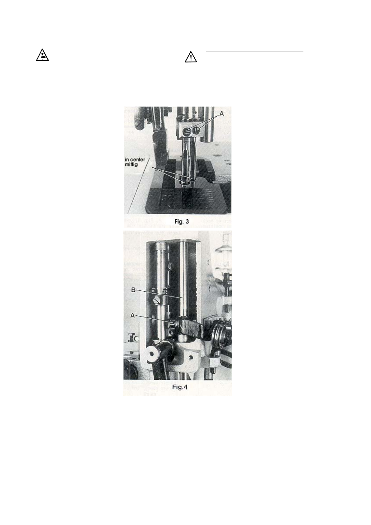
INSERTING THE NEEDLES
Before adjusting the machine
insert a new set of needles with
the shank as far as possible into
the needle holder. The long groove
of the needles must point to the
front (towards the operator).
Tighten the set screws (A, Fig. 3)
on the tapered fastening flats of
the needle shanks.
ALIGNING THE NEEDLE BAR
Remove the face cover and the
finger guard left on the machine
head as well as the upper feed
dog and the presser foot. Rotate
handwheel in operating direction
and check if the needles center in
the associated needle holes of
the throat plate (see Fig. 3). If not
loosen clamp screw (A, Fig. 4) in
the needle bar connection and
turn the needle bar (B)
accordingly. Retighten screw (A.).
HINT: For aligning the needle bar
test plate No. 040 37006 0000
can be used in lieu of the throat
plate. The test plate is an extra
order and charge item.
SETTING THE LOWER LOOPER
FOR THE OVEREDGE STITCH
Remove the cloth plate with hinge
plate and throat plate, the feed
dog, the throat plate support and
the needle guard. Insert the lower
looper (A, Fig. 5) into the rear hole
of the looper lever (B). Now snug
the set screw (C) at the back of
the looper lever against the flat on
the looper shank (E) so that the
lower looper point passes as close
as possible to the spot on the
back of the right needle (R),
without deflecting it. Now tighten
the second screw (D) firmly.
INSERTAR LA AGUJA
Antes de ajustar la máquina inserte un
nuevo juego de agujas, en tal manera
que el cabo de la aguja toque el final de
la barra de aguja y la ranura de la aguja
esté posicionada hacia adelante (en dirección al operador). Apriete los tornillos
(A, Fig. 3) en la superficie plana para
asentar la aguja.
AJUSTE DE LA BARRA DE AGUJA
Remueva la cubierta frontal y el guarda
dedos en la carcasa de la máquina, así
como también el alimentador superior y
el pie prensatelas. Gire el volante en
dirección de operación y verifique que la
aguja cuadre en el hueco para la aguja
en la plancha de aguja. (Ver Fig. 3). Si
no, suelte el tornillo sujetador (A, Fig.
4) en la barra de conexión de la aguja y
gire la barra de aguja (B) como sea
necesario. Apriete el tornillo (A).
DATO: Para alinear la barra de aguja, la
plancha para test No. 040 37006 0000
puede ser utilizada en vez de la plancha
de agua. Esta plancha tiene un costo
adicional y es una orden extra.
AJUSTE DEL LOOPER SUPERIOR
PARA LA PUNTADA MAS ANCHA
Quite la plancha de tela, la plancha
articulada y la plancha de aguja, el alimentador, el soporte de la plancha de
aguja y el guarda agujas. Inserte el
looper inferior (A, Fig. 5) en el hueco
posterior de la palanca del looper (B).
Acomode el tornillo de sujeción (C) detrás de la palanca del looper contra la
parte plana del tronco del looper (E) de
manera tal que el que la punta inferior
del looper pase lo mas cerca posible del
punto en la parte posterior de la aguja
derecha (R) pero sin tocarla. Apriete el
segundo tornillo (D) firmemente.
SETTING HEIGHT OF NEEDLE BAR
Rotate handwheel in operating direction until the point of
lower looper (A, Fig. 5) projects 3 mm (1/8") to the right
from the right side of the right needle. Lower edge of looper
and upper edge of needle eye must be flush in this position.
If an adjustment is necessary loosen clamp screw (A, Fig.
4) in the needle bar connection and move the needle bar
(B) up or down, as required. Care should be taken not to
disturb the alignment of the needle bar when making this
adjustment. Retighten clamp screw.
AJUSTE DE LA ALTURA DE LA BARRA DE AGUJA
Gire el volante en dirección de operación hasta que la punta del
looper inferior (A, Fig. 5) sobresalga 3 mm. a la derecha del
lado derecho de la aguja. En esta posición, el borde del looper y
el borde superior del ojo de la aguja deben estar nivelados. De
ser necesario algún ajuste adicional, suelte el tornillo sujetador
(A, Fig. 4) en la conexión de la barra de aguja y mueva la barra
de aguja (B) hacia arriba o hacia abajo, como sea necesario.
Tenga mucho cuidado de no descuadrar la alineación de la barra de aguja mientras efectúe este ajuste. Apriete de nuevo el
tornillo sujetador.
14
Page 15
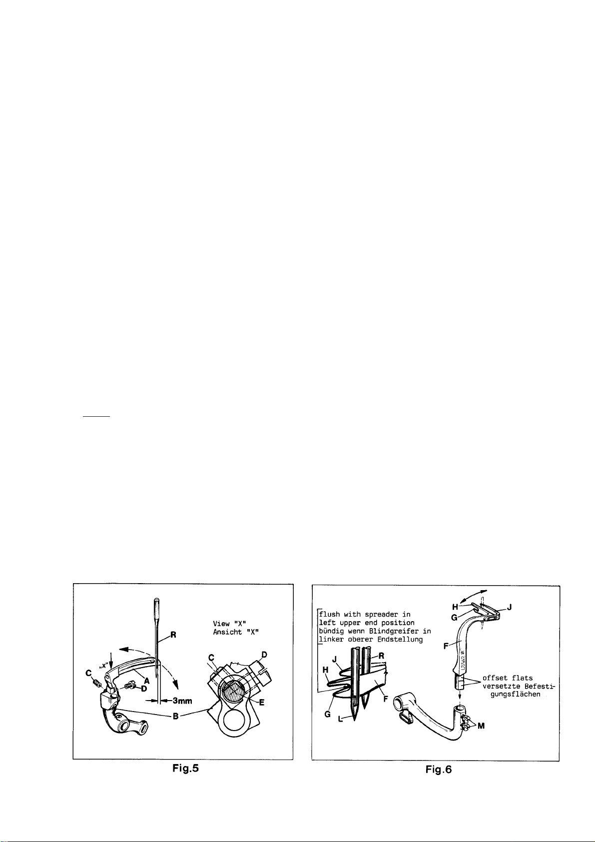
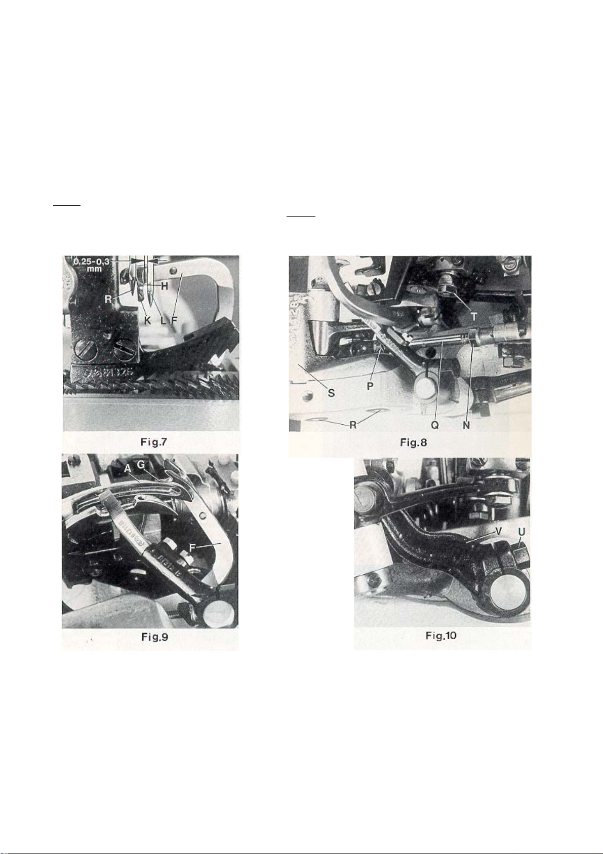
SETTING THE RIGHT UPPER SPREADER FOR THE
OVEREDGE STITCH
AJUSTE DEL SPREADER SUPERIOR PARA LA PUNTADA
MAS ANCHA
Before inserting a new spreader (F, Fig. 6) remove thread
hook (J). This facilitates the visual check of the adjustment.
For adjustment of spreader (F, Figs. 6 and 7) with respect
to the needles (L and R), the shank of spreader (F) has two
offset flats.
Proceed as follows:
First snug one screw (M, Fig. 6) on the flat of the spreader
shank which obtains the following position of the spreader:
When rotating the handwheel in operating direction
spreader (F, Fig. 7) should pass with the tip of its upper
prong (H) in a distance of 0.25 to 0.3 mm (.010 to .012")
behind the left needle (L) and its face (K) should not
contact the front of the right needle (R). Now tighten the
second screw (M, Fig. 6).
HINT: In case the adjusting possibility of the spreader by
means of the two offset flats on the spreader shank is not
sufficient, additionally the complete spreader shaft bearing
(S, Fig. 8) can be moved slightly up or down when
loosening screws (R). Retighten screws.
In the extreme left upper end position of spreader (F, Fig.
6), the bottom of the cutout between the two looper prongs
(G and H) should be flush with the left side of the left
needle (L).
If an adjustment is necessary, loosen nuts (N and P, Fig.
8) and turn connecting rod (Q) forward or backward as
required to obtain the required position.
NOTE: The left nut (P) has a left hand thread.
Temporarily snug the two nuts (N and P)
manually.
Remount thread hook (J, Fig. 6) on spreader (F).
Rotate handwheel in operating direction until the spreader
is in its extreme right lower end position. The spreader
should not contact any machine parts during its motion.
If required loosen clamp screw (U, Fig. 10) in the spreader
drive lever (V) and set the lever so that the spreader (F)
clears at all points. Retighten clamp screw.
Antes de colocar el nuevo spreader (F, Fig. 6) retire el gancho
retenedor del hilo (J). Esto permite visualizar mejor el ajuste.
Para ajustar el spreader superior (F, Figs. 6 y 7) con respecto
a las agujas (L y R) el cuello del spreader (F) tiene dos
superficies planas.
Proceda de la siguiente manera:
Primero acomode un tornillo (M, Fig. 6) contra la parte plana del
cuello del spreader, con lo cual se alcanzará la siguiente
posición del spreader: Cuando se gire el volante en dirección
de costura, el spreader (F, Fig. 7) debe pasar con la punta de
su tenaza (H) a una distancia de 0.25 a 0.3 mm por detrás de
la aguja izquierda (L) y su cara (K) no debe tocar el frente de la
aguja derecha (R). Apriete el segundo tornillo (M, Fig. 6).
DATO: En el caso de que de haber hecho el ajuste del spreader
a ambos lados del tronco no sea suficiente, se recomienda
mover el rodamiento del looper (S, Fig. 8) ligeramente hacia
arriba o hacia abajo, cuando se suelten los tornillos (R). Apriete
los tornillos.
En la extrema posición superior izquierda del spreader (F, Fig.
6) la parte inferior del corte entre las tenazas del looper (G y H)
debe estar al nivel del lado derecho de la aguja izquierda (L).
De ser necesario un ajuste, afloje las tuercas (N y P, Fig. 8) y
gire la varilla de conexión (Q) hacia adelante o hacia atrás,
como sea requerido, hasta obtener la posición adecuada.
NOTA: La tuerca izquierda (P) enrosca a la izquierda.
Temporalmente ajuste las dos tuercas (N y P)
manualmente.
Monte de nuevo el gancho retenedor del hilo (J, Fig.6) en el
spreader (F).
Gire el volante en dirección de operación hasta que el spreader
superior esté en su posición extrema inferior. El spreader no
debe tocar ninguna parte de la máquina durante esta operación. Si es necesario, afloje el tornillo de sujeción (U, Fig. 10)
en la palanca (V) y ajústela de manera tal que el spreader
superior (F) no toque ninguna de estas piezas. Apriete el tornillo
de sujeción.
After this setting recheck the position of the spreader to
the left needle, as described above. Reset with connecting
rod (Q, Fig. 8) if required and tighten nuts (N and P).
Después de realizar este ajuste, verifique la posición del
spreader superior con la aguja, tal y como se describe en el
párrafo anterior. Reajuste con la barra de conexión (Q, Fig. 8)
de ser necesario y apriete de nuevo las tuercas (N y P) .
15
Page 16
SETTING THE RIGHT UPPER SPREADER FOR THE
OVEREDGE STITCH (continued)
AJUSTE DEL SPREADER SUPERIOR PARA LA PUNTADA
MAS ANCHA (Continuación)
Rotate handwheel in operating direction. On the upward
travel of spreader (F, Fig. 9) the tip of its lower prong (G)
must pass as close as possible in the recess behind the eye
of the lower looper (A) without contacting it.
If an adjustment is required, loosen nut (T, Fig. 8) on
the double joint and swing the lower looper lever with lower
looper accordingly to the right or left. Retighten nut (T).
NOTE: Check the setting of the needle bar height
after making this adjustment and reset if
required. Refer to paragraph "SETTING
HEIGHT OF NEEDLE BAR".
Gire el volante en dirección de operación. En la extrema superior
del recorrido del spreader (F, Fig. 9) la punta inferior de su
tenaza (G) debería pasar lo mas cerca posible del espacio detrás
del ojo del looper inferior (A) pero sin tocarlo.
De ser necesario un ajuste, suelte la tuerca (T, Fig. 8 ) en la doble
unión y mueva la palanca del looper inferior con el looper inferior
hacia la derecha o izquierda, como sea necesario. Reajuste la
tuerca (T).
NOTA: Revise la altura de la barra de aguja después de realizar
estos ajustes y reajuste de ser necesario. Refiérase al párrafo
"AJUSTE DE LA ALTURA DE LA BARRA DE AGUJA."
SETTING THE THREAD RETAINER FOR THE
OVEREDGE STITCH
Viewed from the left end of the machine the thread retainer
(B, Fig. 11) should pass as close as possible on the left side
of lower looper (A) when swinging upward without contacting
it.
On the most upward position of its swing motion the thread
retainer (B) should not interfere neither with the bottom of
the throat plate nor with the feed dog.
AJUSTE DEL RETENEDOR DE HILO PARA LA PUNTADA
MAS ANCHA
Visto desde la extrema izquierda del final de la máquina, el
retenedor de hilo (B, Fig. 11) debe pasar tan cerca como sea
posible del lado izquierdo del looper inferior (A) en su movimiento hacia arriba, pero sin tocarlo.
En su posición más alta en este movimiento, el retenedor de hilo
(B) no debe tocar ni la plancha de aguja ni el alimentador.
16
Page 17
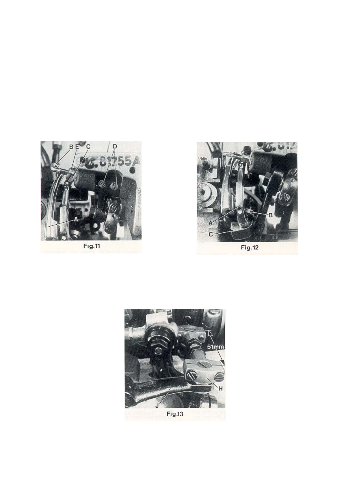
SETTING THE THREAD RETAINER FOR THE
OVEREDGE STITCH (continued)
After loosening screw (C, Fig. 11) the thread retainer (B)
can be moved to the left or right. Retighten screw on the flat
of the thread retainer shank.
After loosening the two set screws (D), shaft (E) with the
thread retainer (B) can be rotated into the correct position.
Make sure to remove all lateral end play when tightening
the set screws.
AJUSTE DEL RETENEDOR DE HILO PARA LA PUNTADA
MAS ANCHA (Continuación)
Después de soltar el tornillo (C, Fig. 11) el retenedor de hilo (B)
puede moverse hacia la izquierda o derecha. Apriete el tornillo
en la parte plana del cuello del retenedor de hilo.
Después de soltar los tornillos de sujeción (D), el cuello (E) con
el retenedor de hilo (B) debe moverse hasta lograr la posición
correcta. Asegúrese de corregir cualquier movimiento fuera de
sitio antes de apretar los tornillos.
SETTING THE DOUBLE LOCKED STITCH LOOPER
Insert the double locked stitch looper (A, Fig. 12) and
tighten it with screw (B) on the flat of its shank so that it
passes as close as possible behind the left needle without
touching it. Now tighten set screw (C).
SETTING THE CROSS LOOPER FOR DOUBLE LOCKED
STITCH
The distance (set at the factory) from center to center of the
two ball joints driving the cross looper should be 51 mm (2")
(see Fig. 13).
Basically the front ball joint (H, Fig. 13) should be positioned
as far as it will go to the left in the fastening slot of the cross
looper drive lever (J).
When rotating the handwheel in
operating direction cross looper (D,
Fig. 14) should swing as close as
possible in the recess behind the
eye over the double locked stitch
looper (A) without contacting it.
At the left end of its swing motion
cross looper (D, Fig. 15) must be
positioned so that the left needle
(L) securely stitches into the thread
loop hanging around the hook of
cross looper (D). In front of the left
needle the cross looper should pass
in a distance of 0.3 mm (.012") (see
Fig. 15).
Check this as follows:
Hang a piece of thread around the
hook of the cross looper and draw it
slightly in sewing direction. Now
rotate handwheel in sewing
direction. The left needle must enter
securely between the two thread
ends.
AJUSTE DEL LOOPER PARA DOBLE PUNTADA DE SEGURIDAD
Inserte el looper para doble puntada de seguridad (A, Fig. 12)
y asegúrelo con los tornillos (B) en la parte plana de su cuello,
de manera que pase tan cerca como sea posible por detrás de
la aguja izquierda pero sin tocarla. Apriete el tornillo (C).
AJUSTE DEL LOOPER CRUZADO PARA DOBLE PUNTADA
DE SEGURIDAD
La distancia (de fábrica) del centro de las dos articulaciones
esféricas que manejan el looper cruzado debe ser de 51 mm
(Ver Fig. 13).
La articulación esférica frontal (H, Fig. 13) debe quedar lo más
lejos posible a la izquierda de la ranura de seguridad de la
palanca del looper cruzado (J).
Girando el volante en dirección de
operación el looper cruzado (D, Fig.
14) debe moverse los más cerca posible del espacio detrás del ojo del looper
para doble puntada de seguridad (A)
pero sin tocarlo.
Al final izquierdo de su recorrido, el
looper cruzado (D, Fig. 15) debe estar
posicionado de manera tal que la aguja izquierda (L) forme la puntada en el
lazo del hilo guindando alrededor de el
gancho retenedor del hilo del looper
cruzado (D). El looper cruzado debe
pasar frente a la aguja izquierda a una
distancia de 3 mm (Ver Fig. 15).
Verifique lo siguiente:
Pase un hilo alrededor de el gancho
retenedor del hilo del looper cruzado y
hálelo ligeramente en dirección de costura. Ahora gire el volante en direccion
de operación. La aguja izquierda debe
entrar tranquilamente entre los dos
hilos.
17
Page 18

SETTING THE CROSS LOOPER FOR DOUBLE LOCKED
STITCH (continued)
After loosening the two screws (E, Fig. 15) the 0.3 mm
(.012") distance to the left needle is adjustable. Retighten
screws on the flat of the cross looper shank.
After loosening clamp screw (G. Fig. 14) cross looper lever
(F) can be raised or lowered for setting the height of cross
looper (D) with respect to the double locked stitch looper
(A) and it can be tilted to the right or left for adjusting the
swing motion of the cross looper with respect to the left
needle. Retighten clamp screw.
If required the length of the path of the cross looper swing
motion can be reduced by positioning ball joint (H, Fig. 13)
to the right in the fastening slot of the cross looper drive
lever (J).
Make sure when setting the cross looper that it does not
interfere with the bottom of the throat plate or other
machine parts.
AJUSTE DEL LOOPER CRUZADO PARA DOBLE PUNTADA
DE SEGURIDAD (Continuación)
Después de aflojar los dos tornillos (E, Fig. 15) la distancia de
0,3 mm de la aguja izquierda es ajustable. Apriete los tornillos
en la parte plana del tronco del looper cruzado. Después de
aflojar el tornillo de sujeción (G, Fig. 14) la palanca (F) del
looper cruzado se puede subir o bajar como sea necesario para
ajustar la altura del looper cruzado (D) con respecto al looper
cruzado para doble puntada de seguridad (A) y puede ser
movido a la derecha o izquierda para ajustar el movimiento del
looper cruzado con respecto a la aguja izquierda. Apriete el
tornillo de sujeción. De ser requerido, se puede reducir el largo
del movimiento del looper cruzado colocando la conexión
esférica (H, Fig. 13) a la derecha de la ranura de seguridad de
la palanca del looper cruzado (J). Asegúrese cuando realice
estos ajustes que el looper cruzado no interfiere con la parte de
la plancha de aguja o alguna parte de la máquina.
SETTING THE NEEDLE GUARD
When the needle guard (A, Fig. 16) is in its most forward
end position, its guarding surfaces should just contact the
back of the needles without deflecting them.
After loosening screw (B, Fig. 16) needle guard (A) can be
moved accordingly to the front or to the rear. Retighten
screw.
NOTE: Any change in stitch length necessitates a
corresponding change in the needle guard
setting.
AJUSTE DEL GUARDA AGUJAS
Cuando el guarda agujas (A, Fig. 16) alcanza su posición
extrema, la superficie de protección debe contactar la parte
trasera de las agujas, pero sin tocarla.
Luego de aflojar el tornillo (B, Fig. 16) el guarda agujas (A)
puede ser movido hacia adelante o atrás como sea necesario.
Apriete de nuevo el tornillo.
NOTA: CADA cambio en el largo de la puntada necesita su
respectivo ajuste en el guarda agujas.
18
Page 19

SETTING THE LOWER FEED
DOG
The lower feed dog (A, Fig. 17)
should center laterally in the slots
of throat plate (B).
If an adjustment is necessary
loosen the two set screws (C,
Fig. 18) and move feed rocker
(D) to the left or right as required.
Retighten set screws.
At highest point of feed travel the
rear teeth of the feed dog (A, Fig.
19) should just project their full
depth above the top surface of
throat plate.
Adjust the supporting screw (E,
Fig. 16) in the feed bar to the
required height and assemble
the feed dog.
THROAT PLATE SUPPORT
Assemble the throat plate support (A, Fig. 20) with screws (B)
so that it does not interfere with the feed dog or any other
machine parts.
AJUSTE DEL ALIMENTADOR INFERIOR
El alimentador inferior (A, Fig. 17) debe
estar centrado lateralmente en la ranura
de la plancha de aguja (B). De ser
necesario algún ajuste, suelte Ios dos
tornillos de sujeción (C, Fig. 18) y mueva el eje oscilante (D) a la izquierda o
derecha, como sea requerido. Apriete
los tornillos de sujeción.
En el punto mas alto de movimiento los
dientes del alimentador (A, Fig. 19)
deberían sobrepasar la plancha de la
aguja por la altura completa de la
superficie de la plancha de aguja.
Apriete el tornillo de soporte (E, Fig. 16)
en la barra alimentadora a la altura
requerida e instale el diente alimentador.
SOPORTE DE LA PLANCHA DE AGUJA
Monte el soporte de la plancha de aguja (A, Fig. 20) con los
tornillos (B) de manera que no interfiera con el alimentador
o con cualquier otra parte de la máquina.
SETTING THE UPPER FEED DOG
Assemble the upper feed dog (B, Fig. 21) and the presser
foot (C). The upper feed dog (B) should not push against
the front or rear end when moving in the slots of presser
foot (C).
Simultaneously the upper feed dog
(B, Fig. 19) should be positioned
so that the tips of its teeth engage
with the tooth spaces of the lower
feed dog (A), without contacting
it. When the lower feed dog (A) is
in its highest and the upper feed
dog (B) in its lowest point of travel,
there must be a small gap between
both feed dogs.
The feed travel of the upper and
the lower feed dog should be
synchronous.
For setting the upper feed dog with
respect to the slot ends in the
presser foot and the tooth spaces
of the lower feed dog, loosen screw
(D, Fig. 21) and turn drive lever (E)
accordingly to the front or rear.
Retighten screw.
AJUSTE DEL DIENTE ALIMENTADOR SUPERIOR
Coloque el diente alimentador superior (B, Fig. 21) y el pie
prensatelas (C). El diente alimentador superior (B) no debe
chocar contra los extremos delantero y trasero durante su
movimiento en las ranuras del pie prensatelas (C).
Simultáneamente el alimentador superior (B, Fig. 19) debe ser ajustado
de tal manera que la punta de sus
dientes coincidan con los espacios
entre los dientes del alimentador inferior (A) sin tocarlo. Cuando el alimentador inferior (A) está en su posición mas alta y el alimentador superior (B) en su posición mas baja, todavía debería haber una distancia
mínima entre los dos transportadores.
Los recorridos de ambos (superior e
inferior) tienen que ser sincronizados.
Para ajustar el alimentador superior
con respecto a los extremos de las
ranuras en el pie prensatelas y los
espacios entre los dientes del alimentador inferior, hay que soltar el tornillo (D, Fig. 21) y girar la palanca de
accionamiento (E) hacia adelante o
atrás respectivamente. Apriete de
nuevo el tornillo.
19
Page 20

SETTING THE UPPER FEED DOG (continued)
For setting the small gap between the feed dogs loosen
nut (F, Fig. 22). Turning in screw (G) increases the gap,
turning it out decreases the gap. Retighten nut (F).
For matching the upper feed dog travel with the lower
feed dog travel loosen screw (A, Fig. 23). Moving the
ball link in the slot of rocker lever (B) to the front
decreases the upper feed dog travel, moving it to the
rear increases the travel. Retighten screw (A).
SETTING THE LIFT MOTION OF THE UPPER FEED
DOG
On the return travel, the upper feed dog should lift so
high that no fabric will be pulled against the sewing
direction.
The motion should be set so that the rear four teeth of
the upper feed dog (B, Fig. 21) remain approx. 1/3 of
their height in the presser foot slots when lifting.
For adjustment loosen the two screws (H, Fig. 22) and
raise the supporting yoke (J) when the upper feed dog
should lift more, or lower it when it should lift less.
Retighten screws (H).
AJUSTE DEL DIENTE ALIMENTADOR SUPERIOR (Continuación)
Para ajustar la pequeña brecha dentro del alimentador , suelte la tuerca (F, Fig. 22). Girando el tornillo (G) hacia adentro
aumenta la brecha, hacia afuera la disminuye. Apriete la tuerca (F) de nuevo. Para ajustar el movimiento del diente superior con el diente inferior, suelte el tornillo (A, Fig. 23). Moviendo la junta esférica en la ranura de la palanca de accionamiento (B) hacia el frente disminuye el movimiento del alimentador superior, moviéndolo hacia atrás lo incrementa.
Apriete de nuevo el tornillo (A).
AJUSTE DEL MOVIMIENTO DEL ALIMENTADOR SUPERIOR
En su movimiento de regreso, el alimentador superior debería moverse tan alto que ningún material sea arrastrado hacia la dirección de costura. El movimiento debe ser ajustado
de manera tal que los últimos 4 dientes traseros del alimentador superior (B, Fig. 21) mantengan aproximadamente 1/3
de su altura de las ranuras del pie prensatelas cuando se
levanta.
Para ajuste, suelte los dos tornillos (H, Fig. 22) y levante el
soporte (J) cuando el diente alimentador superior deba subir
mas, o bájelo cuando deba bajar mas. Apriete los tornillos
(H).
PRESSER FOOT PRESSURE ON 81300A, AJ, B
Rotate handwheel until the lower feed dog is below the
throat plate. Loosen knurled nut (A. Fig. 24) and turn
out T-screw (B) until it does not excert any pressure on
the leaf springs. In this position, the pressure excerted
on the presser foot should be so strong that the presser
foot bottom and the front end of the presser foot tongue
rest squarly on the throat plate.
20
PRESION DEL PIE PRENSATELAS PARA 81300A, AJ, B
Gire el volante hasta que el transporte inferior se encuentre
debajo de la plancha de la aguja. Afloje la tuerca (A, Fig. 24)
y afloje el tornillo (B) hasta que no haga más presión contra
los muelles. En esta posición la presión al pie prensatela
debería ser tal que la planta del pie prensatela y la parte
delantera de la lengüeta del pie prensatela se apoyen plano en
la plancha de aguja.
Page 21

PRESSER FOOT PRESSURE (contiued)
By relocating the collars (C, Fig. 25) which serve as a leaf
spring rest on the left and right presser bar, the pressure can
be changed. Raising the collars increases the pressure,
lowering the collars decreases it.
The presser foot lift is limited with the upper stop collar (D,
Fig. 25) on the right presser bar. When the needles are in their
lowest position and the presser foot is lifted with the presser
foot lifter lever, the needle holder should not contact the
presser foot. Besides this, the lifted presser foot should not
contact the right upper spreader moving upwards. Set the
stop collar (D) accordingly.
Make sure that both presser bars move up and down freely
without binding.
Now turn in T-screw (B, Fig. 24) until the necessary presser
foot pressure for proper feeding is excerted (determine by
sewing tests). Secure this setting with the knurled nut (A),
which simultaneously fastens the upper arm cover. Remount
the face cover and the finger guard.
EDGE GUIDE AND STITCH TONGUE
Set the edge guide (A, Fig. 26) laterally as close as possible
to the presser foot without contacting it. When loosening the
two screws (B), the edge guide (A) can be moved laterally.
Retighten screws.
Set the stitch tongue (C, Fig. 26) so that the rear part of the
thread loop slides over the tongue onto the fabric, while the
front part of the loop is retained until the right needle securely
has entered the loop. After loosening screw (D) the stitch
tongue (C) can be moved to the front or to the rear. When
moving the sitch tongue to the rear, the front part of the thread
loop is retained longer. Retighten screws (D).
On its travel the upper spreader (E, Fig. 26) should not
contact stitch tongue (C).
PRESION DEL PIE PRENSATELAS (Continuación)
Regulando los anillos (C, Fig. 23) en la barra derecha e izquierda
del pie prensatela, que sirven como soporte para los muelles, se
puede variar la presión. Subiendo los anillos aumenta la
presión, bajándolos disminuye la presión.
La elevación del pie prensatelas se limita con el anillo de ajuste
(D, Fig. 25) en la parte superior de la barra derecha del pie
prensatelas. Cuando la aguja está en su posición más baja y el
pie prensatelas levantado el porta agujas no debe tocar el pie
prensatelas. Además, cuando el pie prensatelas está levantado
no debe contactar los movimientos del looper y el spreader
superiores. Apriete el anillo de ajuste (D) adecuadamente.
Asegúrese que ambas barras del pie prensatelas se muevan
libremente hacia arriba y abajo.
Ahora apriete el tornillo (B, Fig. 24) hasta que haya suficiente
presión al pie prensatela para el transporte de la tela (compruebe con ensayos de costura). Apriete esta posición con la tuerca
(A) , con la cual se fija simultáneamente la tapa superior en el
brazo de la máquina. Coloque otra vez la tapa lateral en el brazo
y el protector de los dedos.
GUIA TOPE Y LENGUETA DE COSTURA
Ajuste la guía tope (A, Fig. 26) tan cerca como sea posible al
pie prensatelas, pero sin tocarlo. Cuando suelte los dos tornillos (B) la guía tope (A) podrá moverse lateralmente. Reajuste los tornillos de nuevo.
Ajuste la lengüeta de costura (C, Fig. 26) , de manera tal que la
parte trasera del lazo del hilo desliza sobre la lengüeta en el
tejido, mientras la parte delantera del lazo del hilo queda retenida hasta que la aguja entra al lazo del hilo. Después de
soltar los tornillos (D) la lengüeta de costura (C) podrá moverse hacia adelante o hacia atrás. Cuando la lengüeta de costura
se mueva hacia atrás, la parte frontal del lazo del hilo quedará
retenida por mas tiempo. Reajuste los tornillos de nuevo (D).
Durante el movimiento del spreader superior (E, Fig. 26) no
deben tocar la lengüeta de costura (C).
CHANGING STITCH LENGTH
The length of the stitch can be adjusted by raising or lowering
stud (A, Fig. 27) in the segment slot of feed rocker (C)
located at the rear of machine below the cloth plate. Lowering
stud (A) will lengthen the stitch, raising the stud will shorten
the stitch. After loosening nut (B), stud (A) can be moved
accordingly. When the desired stitch length is obtained,
retighten nut (B).
NOTE: Any change in stitch length necessitates a
corresponding change in the needle guard
setting and matching of the upper feed dog
travel!
CAMBIO DEL LARGO DE PUNTADA
El largo de la puntada se ajusta subiendo o bajando el perno (A,
Fig. 27) en la ranura del marco del transportador (C) ubicado
en la parte posterior de la máquina debajo de la plancha de
aguja. Bajando el perno (A) alarga la puntada, subiendo el perno
acorta la puntada. Después de aflojar la tuerca (B) se puede
mover el perno (A) adecuadamente. Apriete la tuerca (B) otra
vez después de haber fijado el largo de la puntada.
NOTA: Cada cambio en el largo de la puntada necesita que se
ajuste el guarda agujas trasero y el movimiento del diente
alimentador superior!
21
Page 22

NEEDLE THREAD TAKE-UP AND THREAD TENSIONS
ALIMENTACION DEL HILO DE LA AGUJA
Basically the needle thread take-up roller (B, Fig. 2), located
left on the upper bed casting under the face cover, is set as
low as possible.
In case more needle thread should be pulled off (depending
on thread and fabric), raise the needle thread take-up roller
accordingly.
Fasten the needle thread roller guide (C, Fig. 2), located on
the top of the upper bed casting, approx. in the middle of its
shank.
The tension applied on the needle threads should be fairly
strong to produce uniform stitches.
Set the collar for the needle thread tension on the up and
down moving needle bar connection so that its front face is
flush with the face of the tension post.
The tension applied to the double locked stitch looper thread
(stitch type 401) should be very slight and just sufficient to
steady the thread.
The tension applied to the overedge stitch looper thread
(stitch type 502) should be slightly higher than the tension
applied to the double locked stitch looper thread.
SETTING THE TIME RELA YS IN THE SWITCH BOX OF
HOT THREAD CHAIN CUTTER
Styles 81300A1H, B1H
The switch box includes two time relays marked K2T and
K4T.
Set the heat up periode for the knife for hot cutter on
relay K2T to approximately 3 seconds.
Choose the time delay between two cutting operations
on relay K4T. Recommended delay should be set to
approximately 10 seconds.
Generalmente el rodillo del alimentador del hilo de la aguja
(B, Fig. 2), situado en la parte delantera izquierda del brazo
debajo de la tapa frontal, debería estar fijado tan bajo como
sea posible. En el caso que se necesite más hilo para crear
un lazo de hilo más grande (dependiendo del hilo y tela) tiene
que subir el rodillo adecuadamente.
Fije el guía hilo (C, Fig. 2), situado en la parte delantera
superior del brazo, aproximadamente en la mitad de su
mango.
La tensión aplicada a los hilos de las agujas debe ser los
suficiente fuerte para producir puntadas uniformes.
Ajuste el aro de metal de los hilos de las agujas con
movimientos de la conexión de la barra de aguja hacia arriba
y abajo hasta que su frente quede parejo con el del poste de
la tensión.
La tensión aplicada para la tensión del looper para la doble
puntada de seguridad (Costura tipo 401) debe ser ligera y
justo lo suficiente para mantener el hilo. La tensión aplicada
para la tensión del looper para la doble puntada de seguridad
extendida (Costura tipo 502) debe ser ligeramente mayor
que la aplicada para la doble puntada de seguridad.
AJUSTE DE LOS RELES DE TIEMPO EN LA CAJA DE
CONTROL DEL CORTADOR CALIENTE DE CADENETA.
Estilos 81300A1H, B1H
La caja de control incluye dos relés de tiempo marcados
K2T y K4T.
Ajuste a 3 segundos aproximadamente el período de tiem-
po para la cuchilla de corte caliente.
Seleccione el tiempo de espera entre las dos operaciones
de corte en el relé K4T. Se recomienda ajustar a 10 segundos aproximadamente.
TORQUE REQUIREMENTS
Torque specifications given in this catalog are measured
in Nm (Newtonmeter and inch-pound (in.lbs.). All straps
and eccentrics must be tightened to 2.2 - 2.4 Nm (19 - 21
in.lbs), unless otherwise noted. All nuts, bots, screws etc.
without torque specifications must be secured as tightly
as possible, unless otherwise noted. Special torque
specifications of connecting rods, links, screws etc. are
shown on part illustrations.
22
REQUERIMIENTOS DE TORQUE
Las especificaciones de los torques se indican en este
catálogo en Nm (Newtonmetros) y pulgada-libra (in.lbs).
Todos los cojinetes de conexión y excéntricas hay que
apretar con 2,2 – 2,4 Nm (19 – 21 in.lbs) a no ser que se
indique de otra manera. Todas las tuercas, pernos, tornillos
etc. sin indicaciones de torques deberían ser apretadas lo
máximo posible, si no se indica de otra manera. Especificaciones especiales de los torques para barras de conexión,
junturas, tornillos etc. se encuentran en las ilustraciones de
las partes y piezas.
Page 23

VIEWS AND DESCRIPTION
OF PARTS
VISTAS Y DESCRIPCIONES
DE LAS PARTES Y PIEZAS
23
Page 24

24
Page 25

BUSHING, SIGHT FEED OILER, SPRING VALVE OILER
BOCINAS Y PARTES DE LUBRICACION
Ref. No.
Ref. No.
*NOTE: Bushings marked with an asterisk are cemented in the bed
casting. Instead of single bushings we recommend to order the
following repair sets, which include the required amount of bushings
with engineering adhesive and instructions:
IMPORTANT! When cementing align the oil holes in the
Part No.
Parte No.
1*
80862
2*
81373A
3
80293A
4
22894K
5
22894J
6
666-79
7
80846
8
89
9
80644
10
88
11*
80640EA
12*
80694DA
13
M129KR
14
TR54
15
999-216E
16
95861
17
80692EA
18
81240DA
19
29111C
20
81261
21
81260
22
15465F
23
22894W
24
12987A
25
22539
26*
80694DA
27
80885
28
80885C
29
22596D
30
999-106D
31
80885B
32
22891
33
HA81
34
HA95
35
999-212-073
36
M129KA
37
M129KB
38
M129K
39
666-197
40*
81354
41
80689C
42
80689D
29916RED
29916REF
29916REM
29916REL
29916RER
29916REP
29916REH
bushings with the oil holes in the bed casting!
Presser Bar Bushings (Ref. No. 1)
Needle Bar Bushings (Ref. No. 2)
Bushings for upper feed drive shaft
(Ref. Nos. 11 and 12)
Bushings for feed rocker shaft
(Ref. No. 17)
Bushings for looper drive rocker shaft
(Ref. No. 18)
Bushings for crankshaft (Ref. No. 26)
Bushings for cross looper drive shaft
(Ref. No. 40)
Description
Presser Bar Bushing
Needle Bar Bushing
Oil Distributor
Spot Screw, headless
Set Screw
Sight Feed Oiler
Bushing for needle lever shaft
Spot Screw, headless
Plug Screw
Set Screw
Bushing, left for upper feed drive shaft
Bushing, right for upper feed drive shaft
Sticker "OIL"
Transfer
Plug
Screw
Bushing for feed rocker shaft
Bushing for looper drive rocker shaft
Bushing and Cone Shaft Assembly for
looper lever
Bushing
Cone Shaft
Cone
Set Screw
Nut
Plug Screw
Bushing for crankshaft
Ball Bearing Assembly for crankshaft
Retaining Ring
Screw
Deep Groove Ball Bearing
Hub
Screw
Spot Screw, headless
Set Screw
Plug
Transfer ANTAEUS
Transfer HERAKLES
Style Plate
Grooved Drive Pin
Bushing for cross looper drive shaft
Spring Valve Oiler
Spring Valve Oiler
25
Descripción
Bocina de la barra del pie prensatelas
Bocina de la barra de aguja
Distribuidor de aceite
Tornillo de punto fijo, sin cabeza
Tornillo de sujeción
Aceitera
Bocina eje palanca aguja
Tornillo de punto fijo, sin cabeza
Tornillo tapa
Tornillo de sujeción
Bocina, izq. impulsor palanca alim.
Bocina, der. impulsor palanca alim.
Calcomanía "aceite " (OIL)
Calcomanía Union Special
Tapón
Tornillo
Bocina eje oscilante del alimentador
Bocina accionador eje del looper
Conjunto bocina y cono accionador
palanca del looper
Bocina
Cono accionador
Cono
Tornillo de sujeción
Tuerca
Tornillo tapa
Bocina del cigüeñal
Conj. cojinete de bolas del cigüeñal
Anillo retenedor
Tornillo
Cojinete de bolas de canal profundo
Manguito
Tornillo
Tornillo de punto fijo, sin cabeza
Tornillo de sujeción
Tapón
Calcomanía ANTAEUS
Calcomanía HERAKLES
Placa de estilo de la máquina
Pasador
Bocina palanca alim. looper cruzado
Válvula aceitera
Válvula aceitera
*
NOTA: Bocinas marcadas con asterisco están cementadas
en la cama de la máquina. En lugar de bocinas ordinarias,
recomendamos ordenar los siguientes Juegos de repara-
ción, que incluyen las cantidades necesarias de bocinas,
pega no permanente e instrucciones.
Bocinas para pie prensatelas (Ref. No. 1)
Bocinas barra de aguja (Ref. No. 2)
Bocinas para transporte superior
(Ref. Nos. 11 y 12)
Bocinas para eje oscilante del alimentador
(Ref. No.17)
Bocinas eje del movimiento del looper
(Ref. No. 18)
Bocinas del cigüeñal (Ref. No. 26)
Bocinas movimiento looper cruzado
(Ref. No. 40)
NOTA: Cuando use la pega no permanente, alinee
los huecos del aceite en las bocinas con
los huecos en la cama de la carcasa!
Amt. Req.
Cant. Req.
4
2
1
1
1
1
2
2
2
2
1
1
4
1
1
3
2
2
1
1
1
1
2
2
2
2
1
1
3
1
1
2
1
1
1
1
1
1
2
2
2
4
1
1
1
1
1
1
1
Page 26

26
Page 27

Ref.
No.
Part No.
Parte No.
CLOTH PLATE, BASE PLATE, GUARDS AND MISCELLANEOUS COVERS
TAPA Y BASE DE LA CAMA, GUADAS Y OTRAS TAPAS
Description Descripción
Amt. Req.
Cant. Req.
80673CB
1
80888
2
80764
3
35733B
4
81387
5
22528
6
A9453A
7
AS126
8
81301D
9
99711LH
9A*
80437A
10
88B
11
81239
12
80438
13
80440
14
22574
15
99711LHA
16*
95303
17*
80280A
18
96664
19
G105B
20
21681
21
G50-42
22
9A* 99711LH Cloth Plate
consists of:
9 81301D Cloth Plate
16* 99711LHA Insert for cloth plate
17* 95303 Screw
Needle Bar Guard
Arm Cover
T-Screw
Knurled Nut
Face Cover
Screw
Finger Guard
Washer
Cloth Plate Assembly for 81300A, AJ,
A1, A2, B, B2
Cloth Plate Assembly for 81300A1H,
B1H
Hinge Pin
Set Screw
Locking Bolt
Spring
Locking Bolt Knob
Countersunk Screw
Insert for cloth plate
Screw
Base Plate
Roll Pin
Screw with nut and washer
T-Screw for sewing machine
Pin
Protector de la barra de aguja
Cubierta del brazo
Tornillo "T"
Tuerca estriada
Cubierta frontal
Tornillo
Protector de dedos
Arandela
Conj. Tapa de la máquina, para
81300A, AJ, A1, A2, B, B2
Conj. Tapa de la máquina, para
81300A1H, B1H
Pasador eje
Tornillo de sujeción
Perno de seguridad
Resorte
Tirador perno de seguridad
Tornillo remache
Inserto de la tapa
Tornillo
Base de la máquina
Pasador de regulación
Tornillo con tuerca y arandela
Tornillo "T" para máquina de coser
Pasador
9A* 99711LH Tapa de la máquina
consiste de:
9 81301D Tapa de la máquina
16* 99711LHA inserto de la tapa
17* 95303 Tornillo
1
1
1
1
1
2
1
1
1
1
1
2
1
1
1
3
1
2
1
1
4
2
1
27
Page 28

28
Page 29

Ref.
No.
10
11
12
13
14
15
16
17
18
19
20
21
22
23
24
25
26
27
28
29
30
31
32
33
34
34A
35
35A
36
37
38
39
39A
40
41
42
43
44
45
46
47
48
49
59
51
52
53
54
55
56
57
58
59
60
61
62
63
64
65
66
67
68
69
70
71
72
73
74
75
76
1
2
3
4
5
6
7
8
9
Part No.
Parte No.
HS106
81292A
99623A
80669B
80676A
HA1349
HS110A
110-2
107
108
80667
80655A
81256A
22560B
AS135
22560B
81256B
28C
AS137A
22560B
80250C
80250A
81086
22560
HA1286B
12964C
88
80668A
80250D
22743
81283
22743
95
81559A
81559
80759A
80759
BP108
22894Y
22894W
81254B
80655
HS52B
22560
HA1286B
12964C
81086C
81293
92132
80669A
81246
80676
81294
HA58C
HA58F
HA58D
21111
22743
81365A
81365
81386
22560
HA1286B
12964C
81386A
88
80668A
95
81267
93A
AS137C
95
81256
28C
81392
88
21608
80696H
81350D
THREAD TENSIONS AND THREAD GUIDE PARTS
TENSIONES DE LOS HILOS Y PARTES DEL GUIA HILOS
Description
Tension Post
Tension Post
Spacer
Tension Post Ferrule
Tension Disc
Tension Sleeve
Spring for needle thread tension
Spring for looper thread tension
Tension Spring Ferrule
Tension Nut
Pin for tension discs
Pin
Thread Sleeve
Set Screw
Bracket
Set Screw
Thread Sleeve
Set Screw
Thread Eyelet
Set Screw
Needle Thread Roller Guide Assembly
Roller Support
Roller Stud Assembly
Set Screw
Spring
Spring Ball
Set Screw
Thread Guide Roller
Pin
Set Screw
Thread Guide Fork
Set Screw
Set Screw
Needle Bar Connection for straight pin "FK"
Needle Bar Connection for taper pin "GD"
Ndl. Bar Conn. for straight pin "FJ", 81300AJ
Ndl. Bar Conn. for taper pin "GC", 81300AJ
Hex. Head Cap Screw
Set Screw
Set Screw
Eyelet
Thread Guide Pin
Roller Stud Assembly
Set Screw
Spring
Spring Ball
Roller Stud
Thread Guide Roller
Shank Screw
Tension Post Ferrule
Tension Post
Tension Disc
Spacer Ring
Spring Ferrule
Spring
Spring Ferrule
Collar
Set Screw
Needle Thread Take-up Roller
Guide Assembly
Roller Support
Roller Stud Assembly
Set Screw
Spring
Spring Ball
Roller Stud
Set Screw
Thread Guide Roller
Set Screw
Looper Thread Guide
Screw
Bracket
Set Screw
Thread Sleeve
Set Screw
Looper Thread Guide
Set Screw
Thread Guide Hook
Stud
Looper Thread Guide
Descripción
Poste de tensión
Poste de tensión
Distanciador
Inserto poste de tensión
Disco de la tensión
Manga de la tensión
Resorte tensión hilo aguja
Resorte tensión hilo del looper
Distanciador de tensión
Tuerca de tensión
Pasador para discos de tensión
Pasador
Mango del hilo
Tornillo de sujeción
Sujetador
Tornillo de sujeción
Mango del hilo
Tornillo de sujeción
Pasa hilo
Tornillo de sujeción
Conjunto del tira hilo
Soporte
Conj. Perno rodillo
Tornillo de sujeción
Resorte
Bola de resorte
Tornillo de sujeción
Tira hilo
Pasador
Tornillo de sujeción
Tridente del tira hilo
Tornillo de sujeción
Tornillo de sujeción
Con. barra aguja pasador cilíndrico "FK"
Con. barra aguja pasador cónico "GD"
Con. b/a pasador cilíndrico "FJ" 81300AJ
Con. b/a pasador cónico "GC" 81300AJ
Tornillo casquete cabeza hexagonal
Tornillo de sujeción
Tornillo de sujeción
Guía hilo
Pasador guía hilo
Conj. Perno rodillo
Tornillo de sujeción
Resorte
Bola de resorte
Perno rodillo
Rodillo guía hilos
Asa del tornillo
Distanciador de tensión
Poste de tensión
Disco de tensión
Espaciador
Resorte distanciador
Resorte
Resorte distanciador
Abrazadera
Tornillo de sujeción
Conj. Tira hilo
Conj. Guía
Soporte
Conj. Perno rodillo
Tornillo de sujeción
Resorte
Bola de resorte
Perno rodillo
Tornillo de sujeción
Rodillo guía hilos
Tornillo de sujeción
Guía hilos del looper
Tornillo
Sujetador
Tornillo de sujeción
Manguito del hilo
Tornillo de sujeción
Guía hilos del looper
Tornillo de sujeción
Guía gancho retenedor del hilo
Perno
Guía hilos del looper
29
Amt. Req.
Cant. Req.
3
1
1
4
8
4
2
2
4
4
3
2
2
2
1
1
1
1
1
1
1
1
1
1
1
1
1
1
1
1
1
2
1
1
1
1
1
1
2
1
2
1
1
1
1
1
1
1
1
1
1
4
1
1
1
1
1
1
1
1
1
1
1
1
1
1
1
1
1
1
1
1
2
2
1
1
1
1
1
Page 30

30
Page 31

Ref. No.
Ref. No.
Part No.
Parte No.
1
81317
1A
80620H
2
81356B
3
77K
4
81356A
5
96B
6
22580
7
G89
8
81559A
8A
81559
9
BP108
10
22894Y
11
22894W
12
HA54B
12A
HA54A
13
51134Y
13A
51134V
14
666-149
15
80715A
15A
80715
16
22894Y
17
22894C
18
22894J
19
22894H
20
96653
21
BP108
22
80643
23
80776
24
80774
25
80772
26
80771A
26A
80771
27
51134Y
27A
51134V
28
666-149
29
80770A
29A
80770
30
22894Y
31
80769
32
80768
33
79
34
80732A
34A
80732
35
22894AD
36
51134Y
36A
51134V
37
666-149
38
22870
39
258
40
22707
41
907
42
29066LA
43
80650LA
44
22587
45
80656
46
80636A
47
G22515A
48
80630C
49
80630
50
80630G
51
80630D
52
PI18
53
80652
54
22857
55
81322A
56
HA66K
57
80885
58
80621A
59
81321B
60
80
61
80674
62
80
63*
A9469N
64*
22574
* Extra order and charge item.
NEEDLE BAR, NEEDLE LEVER, CRANK SHAFT, HANDWHEEL
BARRAS DE AGUJA, LEVANTADOR AGUJA, EJE PRINCIPAL, VOLANTE
Description Descripción
Needle Bar
Sleeve
Needle Stop Plate
Countersunk Screw
Needle Holder
Set Screw for left needle
Set Screw for right needle
Spot Screw, headless
Needle Bar Conn. for straight pin "FK"
Needle Bar Conn. for taper pin "GD"
Hex. Head Cap Screw
Set Screw
Set Screw
Connecting Link for straight pin
Connecting Link for taper pin
Link Pin, straight, Ø 6.53 mm
Taper Pin
Oil Wick
Needle Lever for straight pin
Needle Lever for taper pin
Set Screw
Set Screw
Set Screw
Set Screw
Roll Pin
Hex. Head Cap Screw
Needle Lever Shaft
Stud
Guide
Washer, leather
Link for straight pin
Link for taper pin
Link Pin, straight, Ø 6.53 mm
Taper Pin
Oil Wick
Lift Lever for straight pin
Lift Lever for taper pin
Set Screw
Sliding Block
Supporting Yoke
Screw
Guide Link for straight pin
Guide Link for taper pin
Set Screw
Link Pin, straight, Ø 6.53 mm
Taper Pin
Oil Wick
Shank Screw
Nut
Screw
Nut
Needle Lever Ball Link
Shell
Screw
Ball Stud
Guide Fork
Screw
Nut, left hand thread
Needle Lever Connection Rod
Oil Felt
Nut, right hand thread
Pin for oil felt
Shell
Screw
Crank Shaft
Woodruff Key
Ball Bearing Assembly
(components see page 25 )
Hub for handwheel
Handwheel
Countersunk Screw
Lock Washer for hub
Countersunk Screw
Adapter
Countersunk Screw for A9469N
Barra de a aguja
Manguito
Placa de parada de la aguja
Tornillo remache
Sujetador de la aguja
Tornillo de sujeción para aguja derecha
Tornillo de sujeción para aguja izquierda
Tornillo de punto fijo, sin cabeza
Con. Barra aguja pasador cilíndrico, "FK"
Con. Barra aguja pasador cónico, "GD"
Tornillo casquete cabeza hexagonal
Tornillo de sujeción
Tornillo de sujeción
Conector para pasador cilíndrico
Conector para pasador cónico
Pasador conector cilíndrico Ø 6.53 mm
Pasador cónico
Mecha para el aceite
Levantador aguja para pasador cilíndrico
Levantador aguja para pasador cónico
Tornillo de sujeción
Tornillo de sujeción
Tornillo de sujeción
Tornillo de sujeción
Pasador de regulación
Tornillo casquete cabeza hexagonal
Eje del levantador de aguja
Perno
Guía
Arandela de cuero
Pasador para conector cilíndrico
Pasador para conector cónico
Pasador conector cilíndrico, Ø 6,53 mm
Pasador cónico
Mecha para el aceite
Levanta palanca para conector cilíndrico
Levanta palanca para conector cónico
Tornillo de sujeción
Bloque corredizo
Yugo de soporte
Tornillo
Guía-conector para pasador cilíndrico
Guía-conector para pasador cónico
Tornillo de sujeción
Pasador conector cilíndrico, Ø 6,53 mm
Pasador cónico
Mecha para el aceite
Tornillo tronco
Tuerca
Tornillo
Tuerca
Conector de bola palanca de aguja
Casco
Tornillo
Perno de bola
Tridente guía
Tornillo
Tuerca, enrosca a la izquierda
Varilla conexión levantador aguja
Fieltro para el aceite
Tuerca, enrosca a la derecha
Pasador fieltro para el aceite
Casco
Tornillo
Cigüeñal
Cuña
Conj. cojinete de bolas
(Componentes ver pág. 25 )
Centro del volante
Volante
Tornillo remache
Arandela de seguridad centro volante
Tornillo remache
Adaptador
Tornillo remache para A9469N
* Pieza tiene que ser ordenada y pagada por separado.
Amt. Req.
Cant. Req.
1
1
1
1
1
1
1
1
1
1
1
1
2
1
1
2
2
1
1
1
1
2
1
1
1
1
1
1
1
1
1
1
1
1
1
1
1
2
1
1
2
1
1
4
1
1
1
1
1
1
1
1
1
2
1
1
1
1
1
1
1
1
1
2
1
1
1
1
1
3
1
1
1
3
31
Page 32

32
Page 33

Ref. No.
Ref. No.
1
2
3
4
5
6
7
8
9
10
11
12
13
14
15
16
17
18
19
20
21
22
23
24
25
26
27
28
29
30
31
32
33
34
35
36
37
38
39
40
41
42
43
44
45
46
47
48
49
50
51
52
53
54
55
56
57
58
59
60
62
63
64
65
66
67
68
69
70
71-89
Part No.
Parte No.
81364
85
81364A
94
81370
81366
81
96B
81363A
11354
271E
97A
21210A
9936
9937
18
81362
269
81363
11354
6040A
97A
69H
9937
81361
BP108
96
81360
482
98
81313B
BP108
22824
G29442L
80236
88F
666-19
PI18
81342
81
95
81336A
22524
81349
81240
80691
81338
74A
81337
G15442P
81345
G15442R
97A
81345A
18
81348
81313
98
74F
99240
18
81339
BP108
81358
81358B
HS36K
81358A
97A
18
LOOPER DRIVE MECHANISM
MECANISMO DE OPERACION DEL LOOPER
Description Descripción
Drive Fork for cross looper
Screw
Guide Plate
Screw
Oil Felt
Drive Eccentric for cross looper
Spot Screw, headless
Set Screw
Ball Joint Assembly
Ball Stud
Shell
Shoulder Screw
Collar
Washer
Nut
Nut
Connecting Rod
Nut, left hand thread
Ball Joint Assembly
Ball Stud
Shell
Shoulder Screw
Washer
Nut
Drive Lever for cross looper
Hex. Head Cap Screw
Set Screw
Shaft
Collar
Set Screw
Cross Looper Lever
Hex. Head Cap Screw
Hex. Head Cap Screw
Looper Drive Eccentric Assembly
Connection
Shoulder Screw
Oil Wick
Pin for oil wick
Eccentric
Spot Screw, headless
Set Screw
Guide Disc
Countersunk Screw
Ball Stud
Rocker Shaft for looper drive
Nut
Rocker Lever
Hex. Head Cap Screw
Rocker Lever
Ball Joint Assembly
Ball Stud
Shell
Shoulder Screw
Washer
Nut
Locking Disc
Lower Looper Lever
Screw
Set Screw
Screw
Nut
Drive Lever for upper spreader
Hex. Head Cap Screw
Ball Joint Assembly
Ball Stud
Washer
Shell
Shoulder Screw
Nut
See following page
Tridente accionador looper cruzado
Fieltro para aceite
Excéntrica accionador looper cruzado
Tornillo de punto fijo, sin cabeza
Tornillo de sujeción
Conj. Articulación esférica
Abrazadera
Arandela
Tuerca
Tuerca
Varilla de conexión
Tuerca, enrosca a la izquierda
Conj. Articulación esférica
Arandela
Tuerca
Accionador looper cruzado
Tornillo casquete cabeza hexagonal
Tornillo de sujeción
Eje
Anilla de metal
Palanca looper cruzado
Tornillo casquete cabeza hexagonal
Tornillo casquete cabeza hexagonal
Conj. excéntrica accionador looper
Eje oscilante accionador looper
Tuerca
Palanca del oscilante
Tornillo casquete cabeza hexagonal
Palanca del oscilante
Conj. Articulación esférica
Arandela
Tuerca
Arandela de seguridad
Palanca looper inferior
Tuerca
Palanca accionador spreader superior
Tornillo casquete cabeza hexagonal
Conj. articulación esférica,
Tuerca
Ver página siguiente
Tornillo
Placa guía
Tornillo
Perno de bola
Casco
Tornillo insertable
Perno de bola
Casco
Tornillo insertable
Tornillo de sujeción
Conexión
Tornillo insertable
Mecha para el aceite
Pasador mecha para el aceite
Excéntrica
Tornillo punto fijo, sin cabeza
Tornillo de sujeción
Disco guía
Tornillo remache
Perno de bola
Perno de bola
Casco
Tornillo insertable
Tornillo de sujeción
Tornillo de sujeción
Tornillo
Perno de bola
Arandela
Casco
Tornillo insertable
Amt. Req.
Cant. Req.
1
1
2
4
1
1
1
1
1
1
1
2
1
1
1
1
1
1
1
1
1
1
2
1
1
1
1
1
1
1
1
1
2
2
1
4
2
2
1
1
1
1
2
1
1
2
1
2
1
1
2
1
4
1
1
1
1
2
2
2
1
1
1
1
1
1
1
2
1
33
Page 34

34
Page 35

Ref.
No.
1 - 70
Part No.
Parte No.
LOOPER DRIVE MECHANISM
MECANISMO DE OPERACION DE LOOPER
Description Descripción
See preceding page
Ver pág. anterior
Amt. Req.
Cant. Req.
18
71
35741A
72
269
73
81357
74
81345
75
81357A
76
97A
77
81348
78
81313A
79
98
80
74F
81
18
83
81251B
84
90
85
81255A
86
81354
87*
318
88
81257
89
*NOTE: Bushings marked with an asterisk are cemented
in the bearing casting. Instead of single bushings we
recommend to order the following repair set, which
includes the required amount of bushings with engineering
adhesive and instructions:
29916REG Bushings for spreader lever shaft
(Ref. No. 87)
Nut
Connecting Rod
Nut, left hand thread
Ball Joint Assembly
Ball Stud
Shell
Shoulder Screw
Locking Disc
Spreader Lever
Set Screw
Set Screw
Nut
Shaft for spreader lever
Screw
Bearing for spreader lever shaft
Bushing
Screw
Washer
Tuerca
Varilla de conexión
Tuerca, enrosque izquierdo
Conj. Articulación esférica
Perno de bola
Casco
Tornillo insertable
Arandela de seguridad
Palanca del spreader
Tornillo de sujeción
Tornillo de sujeción
Tuerca
Eje palanca del spreader
Tornillo
Rodamiento eje del spreader
Bocina
Tornillo
Arandela
*NOTA: Bocinas marcadas con asterisco están cementadas en la cama de la máquina . En lugar de bocinas
ordinarias, recomendamos ordenar los siguientes Jue-
gos de reparación, que incluyen las cantidades necesarias de bocinas, pega no permanente e instrucciones:
Bocinas para palanca del eje del spreader
(Ref. No. 87)
1
1
1
1
1
1
2
1
1
2
2
1
1
1
1
2
2
2
IMPORTANT!When cementing align the oil holes in the
bushings with the oil holes in the bed
casting!
NOTA! Cuando use la pega no permanente,
alinee los huecos del aceite en las
bocinas con los huecos de la cama de
la carcasa!
35
Page 36

36
Page 37

LOWER AND UPPER FEED DRIVE MECHANISM
MECANISMOS DEL TRANSPORTE SUPERIOR E INFERIOR
Ref.
Part No.
No.
Parte No.
80740
1
80791
2
BP108
3
51147
4
95
5
80790
6
BP108
7
96192
8
G29139
9
1230A
10
22587
11
21710
12
21711
13
21712
14
80630C
15
80730
16
15430L
17
80630D
18
G29099Q
19
666-19
20
PI18
21
15430M
22
22587
23
81306
24
22894C
25
22894L
26
81234A
27
81235
28
22894AD
29
80755
30
2145
31
97A
32
36E
33
HS36K
34
21212
35
18
36
80233
37
89
38
11
39
482C
40
22894C
41
8A
42
FP80234BA
43
88
44
22686C
44A*
69H
44B*
51847
44C*
97X
45
HA23
46
93A
47
HA10B
48
93A
49
HS70A
50
10A
51
AS70A
52
18
53
20
54
HA43X
55
22894D
56
G29099R
57
81351
58
22587
59
666-121
60
666-19
61
80654
62
81395
63
22894L
64
80696
65
HA20A
66
HA18A
67
96676
68
* Further parts see page 47 * Otras partes ver pág. 47
Description
Drive Shaft
Drive Lever
Hex. Head Cap Screw
Collar
Set Screw
Rocker Lever
Hex. Head Cap Screw
Washer (as required)
Ball Link
Shell
Screw
Ball Stud
Nut
Washer
Nut, left hand thread
Connecting Rod
Oil Felt
Nut, right hand thread
Drive Eccentric Assembly
Oil Wick
Pin for oil wick
Shell
Screw
Eccentric
Set Screw
Spot Screw, headless
Feed Lever
Stud
Set Screw
Connecting Link Assembly
Shell
Shoulder Screw
Ball Stud
Washer
Ring
Nut
Feed Rocker
Set Screw
Feed Bar Shaft
Collar
Set Screw
Feed Rocker Shaft
Feed Bar Assembly
Set Screw
Stud, 10-32 thread, Ø 4.83 mm
Washer
Nut, 10-32 thread
Screw for feed dog height adjustment
Guide Plate
Screw
Guide
Screw
Oil Felt
Oil Felt
Holder for oil felt
Nut
Washer
Feed Lift Eccentric
Spot Screw, headless
Feed Drive Eccentric Assembly
Connecting Link
Screw
Oil Wick
Oil Wick
Bushing
Eccentric
Spot Screw, headless
Stitch Regulating Stud
Washer
Nut
Roll Pin
Descripción Amt. Req.
Eje impulsor
Palanca accionadora
Tornillo casquete cabeza hex.
Placa de metal
Tornillo de sujeción
Palanca del oscilante
Tornillo casquete cabeza hex.
Arandela (como requerido)
Junta
Casco
Tornillo
Perno de bola
Tuerca
Arandela
Tuerca, enrosca izquierda
Varilla de conexión
Fieltro para el aceite
Tuerca, enrosca a la derecha
Conj. Excéntrica alimentador
Mecha para el aceite
Pasador mecha aceite
Casco
Tornillo
Excéntrica
Tornillo de sujeción
Tornillo punto fijo, sin cabeza
Palanca alimentador
Perno
Tornillo de sujeción
Conj. Conector
Casco
Tornillo insertable
Perno de bola
Arandela
Empaquetadura
Tuerca
Accionador del alimentador
Tornillo de sujeción
Eje barra del alimentador
Anilla de metal
Tornillo de sujeción
Eje accionador del alimentador
Conj. Barra del alimentador
Tornillo de sujeción
Perno, rosca 10-32, Ø 4,83 mm
Arandela
Tuerca, rosca 10-32
Tornillo ajuste transporte
Plancha guía
Tornillo
Guía
Tornillo
Fieltro para el aceite
Fieltro para el aceite
Sujetador fieltro aceite
Tuerca
Arandela
Excéntrica levantador alimentador
Tornillo punto fijo, sin cabeza
Conj. Excéntrica acción alimentador
Conector
Tornillo
Mecha para el aceite
Mecha para el aceite
Bocina
Excéntrica
Tornillo punto fijo, sin cabeza
Perno regulador de la puntada
Arandela
Tuerca
Pasador rollo
37
Cant. Req.
1
1
1
2
2
1
1
1-3
1
1
2
1
1
1
1
1
1
1
1
1
1
1
2
1
1
1
1
1
2
1
1
4
2
1
1
2
1
2
1
2
2
1
1
2
1
1
1
1
1
1
1
2
1
1
1
1
1
1
1
1
1
2
1
1
1
1
1
1
1
1
1
Page 38

38
Page 39

PRESSER BARS, LEAF SPRINGS AND PRESSER FOOT LIFTER LEVER F0R 81300A, AJ.A1, B
BARRAS, MUELLES PARA LAS BARRAS Y LEVANTADOR DEL PIE PRENSATELAS PARA 81300A, AJ, A1, B
Ref.
No.
1
2
3
4
5
6
7
8
9
10
11
12
13
14
14A
15
Part No.
Parte No.
80648
420
80649
80631
94
81566A
99376A
80666D
22894C
80663
80664
80766
80767A
80760A
A10455E
81360A
Description
Lifter Lever
Shoulder Screw for lifter lever
Spring
Guide Plate
Screw
Collar
Screw
Collar
Set Screw
Leaf Spring, upper
Leaf Spring, lower
Spring Rest
Shank Screw
Presser Bar, left for 81300A, AJ, A1, B
Presser Bar, left for 81300A1H, A2,
B1H, B2
Presser Bar, right
Descripción
Palanca del levantador
Tornillo insertable palanca levantadora
Resorte
Placa guía
Tornillo
Anillo de metal
Tornillo
Anillo de metal
Tornillo de sujeción
Ballesta, superior
Ballesta, inferior
Soporte de la ballesta
Tornillo con cuello largo
Barra prensatelas, izq. 81300A, AJ, A1, B
Barra prensatelas, izq. 81300 A1H, A2,
B1H, B2
Barra prensatelas, derecha.
Amt. Req.
Cant. Req.
1
1
1
1
4
2
1
1
2
3
1
1
1
1
1
1
39
Page 40

40
Page 41

ELECTRO-PNEUMATIC PARTS KIT FOR UPPER FEED PRESSURE AND LIFTER FOR 81300A1H, A2, B1H, B2
WITH ELECTRONIC DRIVE
PIEZAS DEL SISTEMA ELECTRONEUMATICO PARA LA PRESION Y LEVANTAMIENTO DEL TRANSPORTE
SUPERIOR Y EL PIE PRENSATELAS PARA 81300A1H, A2, B1H, B2 CON MOTOR ELECTRONICO
Ref. No.
Ref. No.
1-33,35
1-22,
24-35
23A**
34A**
1
2
3*
4
5
6
7
8
9
10
11
12
13
14
15
16
17
18
19
20
21
22
23
24
25
26
27
28
29
30
31
32*
33
34
35
Part No.
Parte No.
A10455-813E
A10455H813E
671A1
999-411G1/8-4
1314003
21233FB
671G22
999-194Q
999-411M5-4
95291
671G23
671C25
80783
99373G
HA20B
999-172C
999-400M5-4
999-430-4-4
99590J
95111
90561K
999-174D
998-429B
999-292
995-735Q
90233CX
99683M
999-179
999-254N
999-254D
999-210A
99683C
90561K
999-411G1/8-6
1314001
999-460M5-4
995-735QH
995-852FH
A10455E
Description
Electro-Pneumatic Parts Kit for upper
feed pressure and lifter for 81300A2,
B2
Electro-Pneumatic Parts Kit for upper
feed pressure, lifter and hot thread
chain cutter for 81300A1H, B1H
Air Cylinder with nut
Corner Connection
PA-Tube 4 x 0.65, length 3 m
Nut
Cylinder Rod End
Air Cylinder with nut
Coupling
Nut
Cylinder Rod End
Connection
Bracket
Screw
Washer
Speed Regulating Valve
Coupling
Coupling
Bracket
Screw
Wood Screw
4 Way Solenoid Valve 24 V DC
Coupler Plug
Coupling
Cable with plug, 37 pins, for 997A735,
not shown
Cable with plug, 6 pins, for 997A730
Filter Regulator Assembly
Filter Regulator
O-Ring
Filter Glass with condense drain
Barbed Fitting
Holder
Wood Screw
Coupling
PA-Tube 6 x 1, length 1.5 m
Speed Regulating Coupling
Cable with plug, 37 pins, for 997A735,
not shown
Cable with plug, 37 pins, for
997A852, not shown
Presser Bar, left for 81300A1H,
A2, B1H, B2, see page 39
Descripción
Piezas del sistema electroneumático para presión y levantamiento del transporte superior
y pie prensatelas para 81300A2, B2
Piezas del sistema electroneumático para presión y levantamiento del transporte superior y
cortador caliente de cadeneta para 81300A1H,
B1H
Cilindro neumático con tuerca
Codo
Tubo PA 4 x 0,65, Largo 3 m
Tuerca
Final varilla del cilindro
Cilindro de aire con tuerca
Acoplamiento
Tuerca
Final varilla del cilindro
Conexión
Sujetador
Tornillo
Arandela
Válvula reguladora de velocidad
Acoplamiento
Acoplamiento
Sujetador
Tornillo
Tornillo para madera
Válvula solenoide 4 vías 24 V DC
Enchufe de acople
Acoplamiento
Cable con enchufe, 37 pines, para
997A735, no se muestra en el dibujo
Cable con enchufe, 6 pines, para 997A730
Conj. Filtro Regulador
Filtro Regulador
Empaquetadura
Vidrio del filtro, con drenaje
Conector, acoplamiento
Sujetador
Tornillo para madera
Acoplamiento
Tubo PA 6 x 1, Largo 1,5 m
Acoplamiento regulador de velocidad
Cable con enchufe, 37 pines, para 997A735,
no se muestra en el dibujo
Cable con enchufe, 37 pines, para 997A852,
no se muestra en el dibujo
Barra prensatelas, izquierda, para 81300A1H,
A2, B1H, B2, ver pág. 39.
Amt.
Req.
1
1
1
1
1
1
1
1
1
1
1
1
1
3
3
1
2
1
1
2
2
1
1
2
1
1
1
1
1
1
1
1
2
1
1
1
1
1
1
* Please indicate part No., description and required length
when ordering.
** Extra order and charge item.
41
* Por favor indique número de parte, descrip-
ción y largo requerido cuando ordene.
** Pieza tiene que ser ordenada y pagada
separadamente.
Page 42

42
Page 43

CONTROL FOR ELECTRO-PNEUMATIC HOT THREAD CHAIN CUTTER FOR 81300A1H, B1H
CONTROL PARA EL SISTEMA ELECTRONEUMATICO DE CORTE CALIENTE DE CADENETA PARA 81300A1H, B1H
Ref. No.
Ref. No.
1
2*
3**
3A**
4
5
6
7
8
9
10
11
12
13
14
15
16
* Please indicate part No., description and required
length when ordering.
* Por favor indique número de parte, descripción y
largo requerido cuando ordene!
Part No.
Parte No.
99712HAE
134001
995-735QH
995-852FH
998-429B
999-174D
90561K
95111
99590J
998-338
999-99
999-176
999-185
999-401G1/8-6
999-411G1/8-6
90235FG
90242TA
Description Descripción
Control for Hot Thread Chain Cutter
PA Tube 6 x 4; 1 m long
Cable for 997A735
Cable for 997A852
Coupler Plug
Solenoid Valve
Screw
Screw
Bracket
Knee Switch
Reduction Valve
Connector
T-Connector
Straight Connector
Corner Connector
Terminal Box, not shown
Control Board, not shown,
see page 45
Amt. Req.
Cant. Req.
Control para cortador caliente de cadeneta
Tubo PA 6x4, Largo 1 m
Cable para 997A735
Cable para 997A852
Enchufe de acople
Válvula del solenoide
Tornillo
Tornillo
Soporte
Interruptor de rodilla
Válvula de reducción
Conector
Conector-T
Conector
Codo
Caja de terminales, no se muestra,
Panel de control, no se muestra, ver
pág.45
1
1
1
1
1
2
2
1
1
1
2
1
1
1
1
1
** Extra order and charge item, see also page 41.
** Pieza tiene que ser ordenada y pagada separadamente. Tambien
ver pág. 41.
43
Page 44

44
Page 45

CONTROL FOR ELECTRO-PNEUMATIC HOT THREAD CHAIN CUTTER 81300A1H, B1H
CONTROL PARA EL SISTEMA ELECTRONEUMATICO DE CORTE CALIENTE DE CADENETA PARA 81300A1H, B1H
Part No.
Parte No.
1
2
Ref. No.
Ref. No.
90242TA
Description
Control Box of hot thread chain cutter
999-315B
Control Board
Descripción
Caja de control para cortador caliente de
cadeneta 999-315B
Panel de control
Amt. Req.
Cant. Req.
1
1
45
Page 46

46
Page 47

ELECTRO-PNEUMATIC HOT THREAD CHAIN CUTTER FOR 81300A1H, B1H
ELEKTROPNEUMATISCH BETÄTIGTER FADENKETTEN-HEISSSCHNEIDER FÜR 81300A1H, B1H
Ref. No.
Ref. No.
1
2
3
4
5
6
7
8
9
10
11
12
13
14
15
16
17
18
19
20
21
22
23
24
25
26
27
28
29
30
31
32
33
34
Part No.
Parte No.
99712H813
999-315B
999-315BAL
999-460M5-4
999-194Q
95403A
95255
95955
99711RHA
99711RH
999-194QB
2166A
99711TH
99711MH
95050
482C
99711QH
99711SH
99711NH
99711UH
999-129CA
95412B
99711LH
999-129CB
99711PH
95059
96123
95050A
95950
2165C1.0
RM3293-3
998-32
999-292
999-430-4-4
Description
El.-Pneum.Hot Thread Chain Cutter
Hot Cutter for thread chain with
control box
Knife for hot cutter, w-shape
Flow Control Connector
Air Cylinder
Screw
Nut
Washer
Drive Link for knife driving arm
Drive Link for cover
Fork Head
Collar
Stud for air cylinder
Support
Screw
Collar
Shaft
Cover
Arm for knife
Bracket
Mikro Valve
Screw
Cloth Plate
Roller Lever
Lever
Screw
Lock Washer
Screw
Washer
Shim Ring
Washer
Pipe Clamp, not shown
Coupling, not shown
Coupling, not shown
Descripción
Cortador caliente electroneumático
Cortador caliente de cadeneta con caja
de controles
Cuchilla, con forma de w
Conector regulador de flujo
Cilindro neumático
Tornillo
Tuerca
Arandela
Conector eje palanca cuchilla
Conector eje cubierta
Cabeza de tridente
Abrazadera de metal
Perno del cilindro de aire
Soporte
Tornillo
Abrazadera de metal
Perno
Cubierta
Brazo de la cuchilla
Soporte
Micro válvula
Tornillo
Tapa máquina
Palanca del rodillo
Palanca
Tornillo
Arandela de seguridad
Tornillo
Arandela
Distanciador
Arandela
Sujetador, no se muestra
Acople, no se muestra
Acople, no se muestra
Amt. Req.
Cant. Req.
1
1
1
4
2
2
6
6
1
1
2
5
1
1
2
1
1
1
1
1
1
2
1
1
1
2
2
1
1
1
2
1
2
2
47
Page 48

48
Page 49

SEWING PARTS
PIEZAS DE FORMACION DE COSTURA
Ref. No.
Ref. No.
Part No.
Parte No.
81326
1
136A
2
81320C
3
81330C
4
22596B
5
81597A-10
6
22596B
7
81324A
8
A10481AC
8A
81324B
8B
A10481BC
8C
78057
9
81305A
10
A10482A
10A
51487
11*
69H
12*
22686C
13*
81585
14
22517
15
81303F
16
22514
17
81303C
18
HS24C
19
81325
20
22567
21
81511
22
90
23
81508
24
74E
25
99240
26
81507
27
81310
28
22KH
29
74F
30
81308B
31
74E
32
99240
33
81311B
34
22824
35
22528
36
A10278B6
37
A10278A10
37A
*SIMILAR PARTS, BUT DIFFERENT THREADS; PLEASE MEASURE DIAMETER OF STUD.
*PARTES SIMILARES, PERO CON DIFERENTE ROSCA, FAVOR MEDIR DIAMETRO DEL PERNO.
Description Descripción
Feed Dog, upper
Screw
Presser Foot Assembly
Presser Foot Bottom
Screw
Presser Foot Tongue, marked "WL"
Screw
Throat Plate for 81300A, AJ
Throat Plate with filler cord guide
opening dia. 6 mm for
81300A1, A1H, A2
Throat Plate for 81300B
Throat Plate with filler cord guide
opening dia. 6 mm for
81300B1H, B2
Countersunk Screw
Feed Dog, lower for 81300A, AJ, B
Feed Dog, lower for 81300A1, A1H,
A2, B1H, B2
Nut, 10-32 thread
Washer
Stud,10-32 thread, Ø 4.83 mm
Throat Plate Support
Screw
Edge Guide
Screw
Stitch Tongue
Screw
Needle Guard
Hex. Head Cap Screw
Thread Retainer for overedge stitch,
marked "GR"
Screw
Looper, lower for overedge stitch
Set Screw
Screw
Spreader, upper for overedge stitch
Thread Hook, marked "GP"
Screw
Set Screw
Looper for double locked stitch
Set Screw
Screw
Cross Looper for double locked stitch,
marked "TL"
Hex. Head Cap Screw
Screw
Guide with filler cord opening
Ø 6 mm
Guide with filler cord opening
Ø 10 mm
Diente alimentador, superior
Tornillo
Conj. Pie prensatelas
Parte inferior del prensatelas
Tornillo
Lengüeta prensatelas, marcada "WL"
Tornillo
Plancha de aguja para 81300 A, AJ
Plancha de aguja con guía para
cordón, diámetro de 6 mm para
81300A1, A1H, A2
Plancha de aguja para 81300B
Plancha de aguja con guía para
cordón, diámetro de 6 mm para
81300B1H, B2
Tornillo remache
Alimentador, inferior, 81300A, AJ, B
Alimentador, inferior, para 81300A1,
A1H, A2, B1H, B2
Tuerca, rosca 10-32
Arandela
Perno, rosca 10-32, Ø 4,83 mm
Soporte plancha de aguja
Tornillo
Guía lateral
Tornillo
Lengüeta de costura
Tornillo
Guarda agujas
Tornillo casquete cabeza hexágonal
Retenedor de hilo para puntada de
sobrehilado, marcado "GR"
Tornillo
Looper inferior para sobrehilado
Tornillo de sujeción
Tornillo
Spreader superior para sobrehilado
Gancho del hilo, marcado "GP"
Tornillo
Tornillo de sujeción
Looper, doble puntada de seguridad
Tornillo de sujeción
Tornillo
Looper cruzado, para doble puntada
de seguridad marcado "TL"
Tornillo casquete cabeza hexágonal
Tornillo
Guía para cordón de relleno,
Ø 6 mm
Guía para cordón de relleno,
Ø10 mm
Amt. Req.
Cant. Req.
1
2
1
1
2
1
2
1
1
1
1
2
1
1
1
1
1
1
2
1
2
1
2
1
1
1
1
1
1
1
1
1
2
2
1
1
1
1
2
2
1
1
1
11*
12*
13*
11*
12*
13*
HA18A
20
99241
G5144
69H
80686C
Nut, Q2 thread
Washer
Stud, Q2 thread, Ø 5.44 mm
Nut, J2 thread
Washer
Stud, J2 thread, Ø 4.62 mm
49
Tuerca, rosca Q2
Arandela
Perno, rosca Q2, Ø 5,44 mm
Tuerca, rosca J2
Arandela
Perno, rosca J2, Ø 4,62 mm
Page 50

50
Page 51

Ref. No.
Ref. No.
Part No.
Parte No.
ACCESSORIES
ACCESORIOS
Description Descripción
Amt. Req.
Cant. Req.
1
2
3
4
5
6
7
8
9
10
11
12
12A
13
14
15
16
G21139
G21139A
G22632F24
22509
21104B11
HA69B
96658
G69R
93064K
22507
90561K
99681J
99681JA
90562D
421
HA118
999-114B
Thread Stand Assembly
Spool Seat
Square-head Bolt
Square-head Bold
Rod
Thread Rod
Roll Pin
Thread Rod Extension
Base
Square-head Bolt
Wood Screw
Belt Guard for handwheel
Belt Guard for handwheel with
synchronizer
Wood Screw
Chain for lifter lever
Threading Hook
Superfast Engineering Adhesive,
content 10 ml
Conjunto Portaconos
Asiento del carrete
Perno cabeza cuadrada
Perno cabeza cuadrada
Varilla
Varilla del portaconos
Pasador de regulación
Extensión varilla portaconos
Base del portaconos
Perno cabeza cuadrada
Tornillo para madera
Protector del volante
Protector del volante con
sincronizador
Tornillo para madera
Cadena palanca levantadora
Enhebrador
Pega no permanente,
contenido 10 ml
4
1
2
1
1
1
1
1
1
2
2
1
1
2
1
1
1
IMPORTANT HINT!
To tighten screws, nuts etc. with the correct torque,
torque screw drivers and torque wrenches with
corresponding tool inserts are available.
For information please order sheet "Tool 1".
51
DATO IMPORTANTE!
Para ajustar tornillos, tuercas, etc. con la fuerza de torque
correcta, tenemos disponibles destornilladores y llaves
con la fuerza de torque correspondiente.
Para mayor información, ordene la hoja "Tool 1"
(Herramienta 1).
Page 52

52
Page 53

ACCESSORIES
ACCESORIOS
Ref. No.
Ref. No.
1
1A
1B
1C
2
3
4
5
6
7
8
9
10
11
12
13
14
15
16
17
18
19
20
21
22
23
24
25
26
27
28
29
30
31
32
33
33A
34
35
36
37
38
39
40
41
42
43
44
45
46
47
48
Part No.
Parte No.
93065D2
93065D3
93065D4
93065D5
93065DA
93065DC2
93065DC3
95067
96203
93065DH
93065DB
93065DD
93065DE
95141A
93065DJ
96902
95250
90709K6
95407
93065DG
93065DF
90709K5
93065DTK
A10287T
A10287G
1021U
95252
95005
96203
93065DT
90805K
95407
A10287F
96658
HA69B
99681J
99681JA
90562D
80463A
96203
21393M
666-166
116
116A
21388R
WR56
TT16
21202
21204
G43294B
90233EB
95182V
Description
Thread Stand, 2 Cones
Thread Stand, 3 Cones
Thread Stand, 4 Cones
Thread Stand, 5 Cones
Thread Stand Base
Cone Support
Cone Support
Screw
Locking Ring
Sleeve
Cone
Thread Guide Rod
Spool Seat Disc
Screw
Clamp Plate
Washer
Nut
Cap
Screw
Pad
Pad
Cap
Thread Stand, 1 cone, bottom
Extension
Rod for thread support
Washer
Nut
Screw
Retaining Ring
Spool Set
Spool Seat Disc
Screw
Extension Rod
Roll Pin
Thread Guide Rod
Belt Guard for handwheel
Belt Guard for handwheel
with synchronizer
Countersunk Wood Screw
Machine Fastening Screw
Locking Ring
Clamp Spring
Oil Drain Reservoir
Wrench, size 9/32" (7.2 mm)
Wrench, size 7/32" (5.5 mm)
Wrench, size 3/8" and 1/2"
(9.5 and 12.7 mm)
Socket Head Wrench,
size 1/8" (3.2 mm)
Tweezers
Screwdriver
Screwdriver
Oil Can
Wire for potential equalization
Ground Screw
Descripción
Portaconos, 2 hilos
Portaconos, 3 hilos
Portaconos, 4 hilos
Portaconos, 5 hilos
Base del portaconos
Soporte del cono
Soporte del cono
Tornillo
Anillo de seguridad
Distanciador
Cono
Varilla Guía hilos
Disco de asiento del carrete
Tornillo
Plato de sujeción
Arandela
Tuerca
Tapa
Tornillo
Almohadilla
Almohadilla
Tapa
Porta conos, 1 hilo, inferior
Extensión
Varilla de los hilos
Arandela
Tuerca
Tornillo
Anilla de retención
Carretes
Disco asiento carrete
Tornillo
Varilla de extensión
Pasador de regulación
Varilla guía hilo
Protector del volante
Protector del volante con
Sincronizador
Tornillo remache para madera
Tornillo sujetador de la máquina
Arandela de seguridad
Resorte sujetador
Reserva del aceite
Llave 7,2 mm
Llave 5,5 mm
Llave 9,5 y 12,7 mm
Llave Allen,
3,2 mm
Pinzas
Destornillador
Destornillador
Lata de aceite
Cable para tierra
Tornillo tierra
Amt. Req.
Cant. Req.
1
1
1
1
1
2
2
2
4
1
4
4
2
2
2
2
1
1
1
-
1
1
1
-
3
3
3
4
1
4
4
2
3
3
3
1
1
1
1
1
1
2
1
1
1
1
1
1
1
5
4
5
4
5
4
4
4
1
1
4
4
4
4
4
4
5
4
5
4
5
4
-
1
1
1
2
2
1
1
1
1
2
1
1
1
1
1
1
3
3
1
1
1
1
1
1
1
1
1
1
1
1
-
53
Page 54

NUMERICAL INDEX OF PARTS
INDICE NUMERICO DE PARTES
Part No. Page
Parte No. Página
1021U ... 53
10455E ... 41
107 ... 29
108 ... 29
10A ... 37
11 ... 37
110-2 ... 29
11354 ... 33
116 ... 53
116A ... 53
1230A ... 37
12964C ... 29
12987A ... 25
1314001 ... 41
1314003 ... 41
134001 ... 43
136A ... 49
15430L ... 37
15430M ... 37
15465F ... 25
18 ... 33, 35, 37
20 ... 37, 49
21104B11 ... 51
21111 ... 29
21202 ... 53
21204 ... 53
21210A ... 33
21212 ... 37
21233FB ... 41
21388R ... 53
21393M ... 53
2145 ... 37
21608 ... 29
2165C1.0 ... 47
2166A ... 47
21681 ... 27
21710 ... 37
21711 ... 37
21712 ... 37
22507 ... 51
22509 ... 51
22514 ... 49
22517 ... 49
22524 ... 33
22528 ... 27, 49
22539 ... 25
22560 ... 29
22560B ... 29
22567 ... 49
22574 ... 27, 31
22580 ... 31
22587 ... 31, 37
22596B ... 49
22596D ... 25
22686C ... 37
22707 ... 31
22743 ... 29
22824 ... 33, 49
22857 ... 31
22870 ... 31
Part No. Page
Parte No. Página
22891 ... 25
22894AD ... 31, 37
22894C ... 31, 37, 39
22894D ... 37
22894H ... 31
22894J ... 25, 31
22894K ... 25
22894L ... 37
22894W ... 25, 29, 31
22894Y ... 29, 31
22KH ... 49
258 ... 31
269 ... 33, 35
271E ... 33
28C ... 29
29066LA ... 31
29111C ... 25
29916RED ... 25
29916REF ... 25
29916REG ... 35
29916REH ... 25
29916REL ... 25
29916REM ... 25
29916REP ... 25
29916RER ... 25
318 ... 35
35733B ... 27
35741A ... 35
36E ... 37
420 ... 39
421 ... 51
482 ... 33
482C ... 37, 47
51134V ... 31
51134Y ... 31
51147 ... 37
51487 ... 49
51847 ... 37
6040A ... 33
666-121 ... 37
666-149 ... 31
666-166 ... 53
666-19 ... 33, 37
666-197 ... 25
666-79 ... 25
671A1 ... 41
671C25 ... 41
671G22 ... 41
671G23 ... 41
69H ... 33, 37, 49
74A ... 33
74E ... 49
74F ... 33, 35, 49
77K ... 31
78057 ... 49
79 ... 31
80 ... 31
80233 ... 37
80236 ... 33
Part No. Page
Parte No. Página
80250A ... 29
80250C ... 29
80250D ... 29
80280A ... 27
80293A ... 25
80437A ... 27
80438 ... 27
80440 ... 27
80463A ... 53
80620H ... 31
80621A ... 31
80630 ... 31
80630C ... 31, 37
80630D ... 31, 37
80630G ... 31
80631 ... 39
80636A ... 31
80640EA ... 25
80643 ... 31
80644 ... 25
80648 ... 39
80649 ... 39
80650LA ... 31
80652 ... 31
80654 ... 37
80655 ... 29
80655A ... 29
80656 ... 31
80663 ... 39
80664 ... 39
80666D ... 39
80667 ... 29
80668A ... 29
80669A ... 29
80669B ... 29
80673CB ... 27
80674 ... 31
80676 ... 29
80676A ... 29
80686C ... 49
80689C ... 25
80689D ... 25
80691 ... 33
80692EA ... 25
80694DA ... 25
80696 ... 37
80696H ... 29
80715 ... 31
80730 ... 37
80732 ... 31
80740 ... 37
80755 ... 37
80759 ... 29
80760A ... 39
80764 ... 27
80766 ... 39
80767A ... 39
80768 ... 31
80769 ... 31
54
Part No. Page
Parte No. Página
80770 ... 31
80771 ... 31
80772 ... 31
80774 ... 31
80776 ... 31
80783 ... 41
80790 ... 37
80791 ... 37
80846 ... 25
80862 ... 25
80885 ... 25, 31
80885B ... 25
80885C ... 25
80888 ... 27
81 ... 33
81086 ... 29
81086C ... 29
81234A ... 37
81235 ... 37
81239 ... 27
81240 ... 33
81240DA ... 25
81246 ... 29
81251B ... 35
81254B ... 29
81255A ... 35
81256 ... 29
81256A ... 29
81256B ... 29
81257 ... 35
81260 ... 25
81261 ... 25
81267 ... 29
81283 ... 29
81292A ... 29
81293 ... 29
81294 ... 29
81301D ... 27
81303C ... 49
81303F ... 49
81305A ... 49
81306 ... 37
81308B ... 49
81310 ... 49
81311B ... 49
81313 ... 33
81313A ... 35
81313B ... 33
81317 ... 31
81320C ... 49
81321B ... 31
81322A ... 31
81324A ... 49
81324B ... 49
81325 ... 49
81326 ... 49
81330C ... 49
81336A ... 33
81337 ... 33
Page 55

NUMERICAL INDEX OF PARTS
INDICE NUMERICO DE PARTES
Part No. Page
Parte No. Página
81338 ... 33
81339 ... 33
81342 ... 33
81345 ... 33, 35
81345A ... 33
81348 ... 33, 35
81349 ... 33
81350D ... 29
81351 ... 37
81354 ... 25, 35
81356A ... 31
81356B ... 31
81357 ... 35
81357A ... 35
81358 ... 33
81358A ... 33
81358B ... 33
81360 ... 33
81360A ... 39
81361 ... 33
81362 ... 33
81363 ... 33
81363A ... 33
81364 ... 33
81364A ... 33
81365 ... 29
81365A ... 29
81366 ... 33
81370 ... 33
81373A ... 25
81386 ... 29
81386A ... 29
81387 ... 27
81392 ... 29
81395 ... 37
81507 ... 49
81508 ... 49
81511 ... 49
81559 ... 29, 31
81559A ... 29, 31
81566A ... 39
81585 ... 49
81597A-10 ... 49
85 ... 33
88 ... 25, 29, 37
88B ... 27
88F ... 33
89 ... 25, 37
8A ... 37
90 ... 35, 49
90233CX ... 41
90233EB ... 53
90235FG ... 43
90242TA ... 43, 45
90561K ... 41, 43, 51
90562D ... 51, 53
907 ... 31
90709K5 ... 53
90709K6 ... 53
Part No. Page
Parte No. Página
90805K ... 53
92132 ... 29
93064K ... 51
93065D2 ... 53
93065D3 ... 53
93065D4 ... 53
93065D5 ... 53
93065DA ... 53
93065DB ... 53
93065DC2 ... 53
93065DC3 ... 53
93065DD ... 53
93065DE ... 53
93065DF ... 53
93065DG ... 53
93065DH ... 53
93065DJ ... 53
93065DT ... 53
93065DTK ... 53
93A ... 29, 37
94 ... 33, 39
95 ... 29, 33, 37
95005 ... 53
95050 ... 47
95050A ... 47
95059 ... 47
95067 ... 53
95110A ... 41
95111 ... 43
95141A ... 53
95182V ... 53
95250 ... 53
95252 ... 53
95255 ... 47
95291 ... 41
95303 ... 27
95403A ... 47
95407 ... 53
95412B ... 47
95861 ... 25
95950 ... 47
95955 ... 47
96 ... 33
96123 ... 47
96192 ... 37
96203 ... 53
96653 ... 31
96658 ... 51, 53
96664 ... 27
96676 ... 37
96902 ... 53
96B ... 31, 33
97A ... 33, 35, 37
97X ... 37
98 ... 33, 35
99240 ... 33, 49
99241 ... 49
9936 ... 33
9937 ... 33
Part No. Page
Parte No. Página
99373G ... 41
99376A ... 39
995-735QH ... 41, 43
995-852FH ... 41, 43
99590J ... 41, 43
99623A ... 29
99681J ... 51, 53
99681JA ... 51, 53
99683C ... 41
99683M ... 41
99711LH ... 27, 47
99711LHA ... 27
99711MH ... 47
99711NH ... 47
99711PH ... 47
99711QH ... 47
99711RH ... 47
99711RHA ... 47
99711SH ... 47
99711TH ... 47
99711UH ... 47
99712H813 ... 47
998-32 ... 47
998-338 ... 43
998-429B ... 41, 43
999-106D ... 25
999-114B ... 51
999-126 ... 41
999-129CA ... 47
999-129CB ... 47
999-172C ... 41
999-174D ... 41, 43
999-176 ... 43
999-179 ... 41
999-185 ... 43
999-194Q ... 41, 47
999-194QB ... 47
999-210A ... 41
999-212-073 ... 25
999-216E ... 25
999-254D ... 41
999-254N ... 41
999-292 ... 41, 47
999-315B ... 47
999-315BAL ... 47
999-400M5-4 ... 41
999-401G1/8-6 ... 43
999-411G1/8-4 ... 41
999-411G1/8-6 ... 43
999-411M5-4 ... 41
999-430-4-4 ... 41, 47
999-460M5-4 ... 47
999-460MS-4 ... 41
999-99 ... 43
A10278A10 ... 49
A10278B6 ... 49
A10287F ... 53
A10287G ... 53
55
Part No. Page
Parte No. Página
A10287T ... 53
A10455-813E ... 41
A10455H813E ... 41
A10481AC ... 49
A10481BC ... 49
A10482A ... 49
A9453A ... 27
A9469N ... 31
AS126 ... 27
AS135 ... 29
AS137A ... 29
AS137C ... 29
AS70A ... 37
BP108 ... 29, 31, 33, 37
BP10881358 ... 33
FP80234BA ... 37
G105B ... 27
G15442P ... 33
G15442R ... 33
G21139 ... 51
G21139A ... 51
G22515A ... 31
G22632F24 ... 51
G29099Q ... 37
G29099R ... 37
G29139 ... 37
G29442L ... 33
G43294B ... 53
G50-42 ... 27
G5144 ... 49
G69R ... 51
G89 ... 31
HA10B ... 37
HA118 ... 51
HA1286B ... 29
HA1349 ... 29
HA18A ... 37, 49
HA20A ... 37
HA20B ... 41
HA23 ... 37
HA43X ... 37
HA54A ... 31
HA58C ... 29
HA58D ... 29
Page 56

 Loading...