

Page 1
INSTRUCTIONS, ENGINEER’S AND ILLUSTRATED PARTS
MANUAL
INSTRUCCIONES, MANUAL DEL INGENIERO Y LISTADO
ILUSTRADO DE PARTES
CLASS 80800 - AUT OMATIC SEWING MACHINES
FOR CLOSING FILLED BAGS
CLASE 80800 - MAQUINAS AUTOMATICAS
PARA CERRAR SACOS LLENOS
MANUAL NO. G280 E
FOR STYLES / PARA ESTILOS
80800R, S, RL, SL, TL, TAL, U, UL, UA, UAL
Page 2

MANUAL NO. G280
INSTRUCTIONS FOR 80800 SERIES MACHINES
Seventh Edition Copyright 2003
by
Union Special GmbH Rights Reserved in All Coun-
tries
Printed in Germany
INSTRUCCIONES PARA MAQUINAS DE LA SERIE
MANUAL NO. G280 E
80800
Séptima Edición Propiedad Literaria 2003
por Union Special GmbH Derechos Reservados en
todos los países
Impreso en Alemania
PREFACE
This manual has been prepared to guide you while
operating 80800 series machines and arranged to simplify ordering wear and spare parts.
This manual explains in detail the proper settings for
operation of the machines. Illustrations are used to show
the adjustments and reference letters are used to point
out specific items discussed.
Careful attention to the instructions and cautions for
operating and adjusting these machines will enable you
to maintain the superior performance and reliability
designed and built into every Union Special bag closing
machine.
Adjustments and cautions are presented in sequence so
that a logical progression is accomplished. Some adjustments performed out of sequence may have an
adverse effect on the function of the other related parts.
This manual has been comprised on the basis of available information. Changes in design and / or improvements may incorporate a slight modification of configuration in illustrations or cautions.
INTRODUCCION
Este manual fue preparado para guiar al usuario en la
operación de maquinas de la serie 80800 y ayudar para
simplificar la elaboración de los pedidos de los repuestos.
Este manual explica detalladamente los ajustes para la
operación de la maquina. Las ilustraciones sirven para
demostrar los ajustes y las letras en referencia indican
los puntos específicos discutidos.
Una cuidadosa atención a las instrucciones y las
precauciones operando y ajustando estas maquinas le
va a permitir mantener el mejor funcionamiento y la
confiabilidad que caracteriza las maquinas cerradoras
de sacos de Union Special.
Los ajustes y precauciones son presentados en
secuencia para que se consiga una progresión lógica.
La ejecución de algunos ajustes fuera de la secuencia
puede causar un efecto adverso para el funcionamiento
de otras partes relacionadas.
Este manual se comprende a base de la información
actual. Cambios en diseño y/o mejoras pueden significar
leves modificaciones de la configuración de las
ilustraciones o precauciones.
On the following pages will be found illustrations and
terminology used in describing the instructions and the
parts for your machine.
In addition to the instructions and to the mandatory rules
and regulations for accident prevention and environmental
protection in the country and place of use of the machine
/ unit, the generally recognized technical rules for safe
and proper working must also be observed.
The instructions are to be supplemented by the respective
national rules and regulations for accident prevention and
environmental protection.
En las paginas siguientes se encuentran ilustraciones y
terminologías usadas en la descripción de las
instrucciones y las piezas de la maquina.
Adicionalmente a las instrucciones, las reglas y
regulaciones obligatorias para prevenir accidentes y la
protección ambiental del país y lugar donde se encuentra
la maquina/unidad, hay que considerar las reglas
técnicas para un trabajo seguro y adecuado.
Las instrucciones hay que complementarlas con las
respectivas reglas y regulaciones nacionales contra
accidentes y protección del ambiente.
2
Page 3

TABLE OF CONTENTS
TABLA DE CONTENIDOS
Page
Pag.
PREFACE
INTRODUCCION
IDENTIFICATION OF MACHINES, STYLES OF MACHINES
IDENTIFICACION DE LA MAQUINAS, ESTILOS DE MAQUINAS
SAFETY RULES
REGLAS DE SEGURIDAD
NOISE EMISSION
EMISION DE RUIDO
OILING DIAGRAM, LUBRICATION AND OPERATION, NEEDLES, THREADING
DIAGRAMA DE LUBRICACION, LUBRICACION Y OPERACION, AGUJAS, DIAGRAMA PARA ENHEBRAR
THREADING THE MACHINE
ENHEBRANDO LA MAQUINA
ADJUSTING INSTRUCTIONS
INSTRUCCIONES DE AJUSTE
ORDERING WEAR AND SPARE PARTS
PEDIDOS DE REPUESTOS
EXPLODED VIEWS AND DESCRIPTION OF PARTS
ILUSTRACIONES Y DESCRIPCIONES DE PIEZAS
BUSHINGS AND OILING PARTS
BOCINAS Y PUNTOS DE LUBRICACION
CLOTH PLATES AND MISCELLANEOUS COVERS
TAPA FRONTAL Y OTRAS TAPAS
THREAD TENSIONS, THREAD GUIDES AND NEEDLE BAR GUARD
TENSIONES DE HILO, GUIA HILOS Y PROTECTOR DE LA BARRA DE LA AGUJA
NEEDLE BAR, NEEDLE LEVER, CRANKSHAFT, PULLEY, LOOPER DRIVE AND LOOPER
AVOID ECCENTRIC
BARRA DE LA AGUJA, PALANCA DE MOVIMIENTO DE LA AGUJA, CIGUENAL, VOLANTE, ECCENTRICAS
DEL ACCIONAMIENTO DEL LOOPER
LOOPER AVOID ECCENTRIC FORK, LOOPER, LOOPER DRIVE LEVER AND ROCKER,
LOOPER THREAD CAST-OFF
HORQUILLA PARA LA EXCENTRICA DEL LOOPER, LOOPER, ACCIONAMIENTO DEL LOOPER Y
ALIMENTADOR DEL HILO DEL LOOPER
FEED MECHANISM
DIENTES DEL ARRASTRE
PRESSER BAR, PRESSER BAR SPRINGS AND PRESSER FOOT LIFTER PARTS
BARRA DEL PRENSA TELA, RESORTES DE LA BARRA DEL PRENSA TELA, PIEZAS PARA LEVANTAR EL PRENSA TELA
AIR CYLINDER DRIVE ASSEMBLY AND SOLENOID DRIVE ASSEMBLY FOR CUTTER
CLILINDRO NEUMATICO Y SOLENOIDE DEL CORTADOR
FEELER, PROXIMITY SWITCH, THREAD CHAIN CUTTER FOR STYLES 80800R, S, RL AND SL
PALPADOR, INTERRUPTOR DE PROXIMIDAD, CORTADORES DE CADENETA PARA ESTILOS 80800R, S, RL Y SL
TAPE CUTTER FOR STYLES 80800U, UA, UL AND UAL
CORTADOR DE CINTA PARA ESTILOS 80800U, UA, UL Y UAL
TAPE CUTTER FOR STYLES 80800TL AND TAL
CORTADOR DE CINTA PARA ESTILOS 80800TL Y TAL
PRESSER FEET, THROAT PLATES AND FEED DOGS
PRENSA TELA, PLACA DE AGUJA Y DIENTES DE ARRASTRE
TAPE REEL ASSEMBLY FOR STYLES 80800TL, TAL, U, UA, UL, UAL
PORTA CINTA PARA ESTILOS 80800TL, TAL, U, UA, UL, UAL
TAPE FOLDER FOR STYLES 80800U, UL, MACHINE FASTENING SCREWS
DOBLADILLADORES PARA ESTILOS 80800U, UL, TORNILLOS PARA FIJAR LA MAQUINA
ADHESIVE TAPE FOLDER AND GUIDE ROLLERS FOR ADHESIVE TAPE FOR STYLES 80800TL AND TAL
AND BAG GUIDE RAIL FOR STYLE 80800TL
DOBLADILLADOR PARA CINTAS ADHESIVAS Y RODILLOS DE GUIA PARA LA CINTA ADHESIVA PARA
ESTILOS 80800TL Y TAL Y GUIA PARA LOS SACOS PARA ESTILO 80800TL
ACCESSORIES AND ADDITIONAL ACCESSORIES FOR MOUNTING THE SEWING MACHINE ON FORMER BAG CLOSING COLUMNS
WITHOUT TRAVERSE AND ON BAG CLOSING COLUMNS 20600 WITH TRAVERSE
ACCESORIOS Y ACCESORIOS ADICIONALES PARA MONTAR LA MAQUINA EN COLUMNAS ANTERIORES SIN TRAVESANO Y
EN COLUMNAS 20600 CON TRAVESANO
NUMMERICAL INDEX OF PARTS / INDICE NUMERICO DE PIEZAS
2
4 - 5
6 - 7
8
8 - 9
10
11 - 21
22
23 - 55
24 - 25
26 - 27
28 - 29
30 - 31
32 - 33
34 - 35
36 - 37
38 - 39
40 - 41
42 - 43
44 - 45
46 - 49
50 - 51
50 - 51
52 - 53
54 - 55
56 - 58
3
Page 4

IDENTIFICATION OF MACHINES
Each UNION SPECIAL machine is identified by a Style number , which
on this Class machine is stamped into the Style plate affixed to the right
front of machine. Serial number is stamped into bed casting at the right
front base of machine.
IDENTIFICACION DE LA MAQUINAS
Cada maquina Union Special está identificada con un numero de estilo,
que en este tipo de maquina esta estampado en una placa que está
fijada en la parte derecha frontal de la maquina. El número del serial
está troquelado en la base frontal de la carcasa.
STYLES OF MACHINES
High performance automatic sewing machines with automatic start and
stop of the machine and automatically operated thread chain and tape
cutters. For closing filled bags and sacks made of jute, cotton, paper,
plastic or woven polypropylene tapes as well as bituminized or foil
laminated materials.
Equipped with guides for application of filler cord sealing the needle
punctures.
The bag being fed into the machine starts the sewing operation by a
feeler controlled, contactless, electronic proximity switch. When the bag
is closed, the machine stops automatically. Thread chain, respectively
thread chain with binding tape, are cut automatically.
One Needle, High Throw , Manual Lubrication, Lateral Looper Travel, Plain
Feed, Weight net: 30 kg.
80800R Sewing machine for closing filled bags and sacks of all kinds
with a two thread double locked stitch. With solenoid operated thread
chain cutter. Degree of protection of the cutting solenoid: IP54 (IEC 529).
Seam Specification: 1.01.01/401* (401 SSa-1**)
Stitch range: 2 1/2 to 4 S.P .I. (6.5 to 11 mm)
Standard setting: 3 S.P.I. (8 mm)
Capacity under presser foot: 7/16" (11 mm), adjust able
up to 5/8" (16 mm)
Sewing capacity on paper bags: up to 32 plies of paper
Working dia. of handwheel: 4 1/4" (108 mm)
Maximum speed: up to 1800 stitches/min., depending
on stitch length and speed of conveyor as well as on
operation and material.
80800S same as style 80800R, but single thread chain stitch, seam
specification 1.01.01/101* (101 SSa-1**).
80800RL same as style 80800R, except with electro-pneumatically
operated thread chain cutter.
Operating pressure 44 to 59 psi (3 to 4 bar).
Degree of protection of the solenoid valve: IP65 (IEC 529).
80800SL same as style 80800S, except with electropneumatically
operated thread chain cutter.
Operating pressure 44 to 59 psi (3 to 4 bar).
Degree of protection of the solenoid valve: IP65 (IEC 529).
80800TL Sewing machine for closing filled bags and sacks made of
paper or plastic foil (minimum thickness of foil .007" (0.18 mm) with a
two thread double locked stitch, and simultaneously folding a 2" (50
mm) or 2 3/8" (60 mm) wide self-adhesive crepe paper tape over the
closed mouth of the bag and the seam, which seals the bag closing
seam very tight.
Electro-pneumatically operated thread chain and tape cutter. Operating pressure 44 to 59 psi (3 to 4 bar).
Degree of protection of the solenoid valve: IP65 (IEC 529).
The projecting length of tape on both ends of bag is approx. 1 1/
2" (35 mm).
Seam specification: 3.01.01/401* (401 BSa-1**)
Stitch range: 2 1/2 to 3 S.P.I. (6,5 to 8 mm)
Standard setting: 3 S.P.I. (8 mm)
Capacity under presser foot: 9/32" (7 mm)
Sewing capacity on paper bags: up to 24 plies of paper
Working dia. of handwheel: 4 1/4" (108 mm)
Maximum speed: up to 1200 stitches/min., depending on
stitch length and speed of conveyor, as well as on
operation and material.
Recommended self-adhesive crepe paper tape:
Part No. 999-114TB50, Wi dth: 50 mm (2"),
Color: chamois.
Part No. 999-1 14TB60, Width: 60 mm (2 3/8")
Color: chamois.
Length of roll 200 m (219 yd.)
Root dia of roll 76 mm (3")
* according to ISO 4916 and 4915
** according to Federal S tandard No. 751a (USA)
ESTILOS DE MAQUINAS
Las maquinas son de alto rendimiento que arrancan y paran
automáticamente y con cortadores automáticos de la cadeneta de hilos y
de las cintas. Las maquinas son para cerrar bolsas y sacos hechos de
yute, algodón, papel, plástico o polipropileno tejido y material de betún o
laminado.
Las maquinas están equipadas con guías para la aplicación de cordeles
para sellar los huecos causados por la aguja.
El saco que entra en la maquina empieza la operación de coser mediante
un interruptor electrónico de aproximación, activado por un palpador.
Cuando el saco este cerrado, la maquina para automáticamente. La
cadeneta o la cadeneta con la cinta de papel están cortados
automáticamente.
La maquina tiene una aguja, largo recorido de la aguja, lubricación manual,
recorrido lateral del looper y transporte simple, peso neto 30 kg.
80800R cerradora de sacos llenos y sacos de todo tipo con costura de
cadeneta de dos hilos. Tiene cortador de cadeneta activado por solenoide.
Grado de protección del solenoide IP54 (IEC 529)
Tipo de costura: 1.01.01/401* (401 Ssa-1**)
Largo de la puntada: 2 ½ a 4 S.P.I. (6,5 a 11 mm)
Ajuste normal: 3 S.P.I. (8 mm)
Capacidad debajo del pie: 7/16" (11 mm), ajustable hast a
5/8" (16 mm)
Capacidad para sacos de papel : hasta 32 pliegos
Diámetro del volante: 4 ¼“ (108 mm)
Velocidad máxima: hasta 1800 punt adas/min., dependiendo del largo de
la puntada, velocidad de la cinta transportadora y la operación y el material.
80800S idéntica a la 80800R, pero con costura de cadeneta de un solo
hilo, tipo de costura 1.01.01/101* (101Ssa-1**)
80800RL idéntica a la 80800R, pero con cortador del hilo de la cadeneta
electro neumático.
Presión en operación 44 a 59 psi ( 3 a 4 bar)
Grado de protección del solenoide IP65 (IEC 529)
80800SL idéntica a la 80800S, pero con cortador del hilo de la cadeneta
electro neumático.
Presión en operación 44 a 59 psi ( 3 a 4 bar)
Grado de protección del solenoide IP65 (IEC 529).
80800TL Maquina para cerrar bolsas o sacos de papel o plástico (grosor
mínimo .007" /.18 mm) con costura de cadeneta de 2 hilos, aplicando
simultáneamente una cinta autoadhesiva de 2" (50 mm) o 2 cintas de 3/
8" (60 mm) sobre la boca del saco y la costura, sellando de esta manera
la costura de herméticamente.
Cortador electro neumático para la cadeneta y la cinta. Presión de
operación: 44 a 59 psi (3 a 4 bar)
Grado de protección para el solenoide: IP 65 (IEC 529)
La cinta sobresale en ambos lados del saco 1 ½“ (35 mm)
Tipo de costura: 3.01.01/401* (401BSa-1**)
Largo de la puntada: 2 ½ a 3 S.P.I. (6,5 a 8 mm)
Ajuste normal: 3 S.P.I. (8 mm)
Capacidad debajo del pie: 9/32" (7 mm)
Capacidad para sacos de papel : hasta 24 pliegos
Diámetro efectivo del volante: 4 ¼“ (108 mm)
Velocidad máxima: hasta 1200 punt adas/min., dependiendo del largo de
la puntada, velocidad de la cinta transportadora y la operación y el material.
Cinta autoadhesiva recomendada:
P/P No. 999-1 14TB50, ancho 50 mm (2")
Color chamois
P/P No. 999-1 14TB60, ancho 60 mm (2 3/8"),
Color chamois.
Largo 200m (219yd.)
Diámetro interior del rollo 76 mm (3")
* según ISO 4916 y 4915
** según Fed. Standard No. 751a ( USA)
4
Page 5
80800TAL same as style 80800TL, but for use with combined bag
feed-in and trimming device GBR29920.
80800TAL idéntica al 80800TL, pero en combinación con el
alimentador y cortador de sacos GBR29920.
80800U Sewing machine for closing filled bags and sacks made of
paper or plastic foil (minimum thickness of foil .007" (0.18 mm) with
a two thread double locked stitch, and simultaneously binding the
bag mouth with a 2" to 2 3/4" (50 to 70 mm) wide crepe paper or
plastic tape (folder adjustable). With solenoid operated thread chain
and tape cutter.
Degree of protection of the cutting solenoid: IP54 (IEC 529).
The projecting length of tape on both ends of bag is approx. 1 5/8"
(40 mm).
Seam specification: 3.01.01 / 401* (401 BSa-1**)
Stitch range: 2 1/2 to 4 S.P .I. (6.5 to 10 mm)
Standad setting: 3 S.P.I. (8 mm)
Capacity under presser foot: 9/32" (7 mm)
Sewing capacity on paper bags: up to 24 plies of paper
Working dia. of handwheel: 4 1/4" (108 mm)
Maximum speed: up to 1800 stitches/min., depending
on stitch length and speed of
conveyor, as well as on operation
and material.
80800UL same as style 80800U, except with electro-pneumatically
operated thread chain and tape cutter. Operating pressure 44 to 59
psi (3 to 4 bar).
Degree of protection of the solenoid valve: IP65 (IEC 529).
80800UA, same as style 80800U, except without tape folder. For
use with combined bag feed-in, trimming- and taping device No.
GBR29910.
80800UAL same as style 80800UL, except without tape folder. For
use with combined bag feed-in, trimming- and taping device No.
GBR29910.
80800U Maquina para cerrar bolsas y sacos de papel y plástico
(grosor mínimo .007" / 0.18 mm) con costura de doble cadeneta,
aplicando simultáneamente una cinta de papel o plástico de un
ancho de 2" a 2 ¾“ (50 a 70 mm) con un dobladillador ajustable.
El cortador de la cinta y de la cadeneta opera con solenoide.
Grado de protección del solenoide IP54 (IEC 529).
La cinta sobresale en ambos lados del saco en 1 5/8" (40 mm).
Tipo de costura: 3.01.01 / 401* (401 BSa-1**)
Largo de la puntada: 2 ½ a 4 S.P .I. (6,5 a 10 mm)
Ajuste normal: 3 S.P.I.(8 mm)
Capacidad debajo del pie: 9/32" (7 mm)
Capacidad para sacos de papel : hasta 24 pliegos
Diámetro del volante: 4 ¼“ (108 mm)
Velocidad máxima: hasta 1800 puntadas/min., dependiendo del
largo de la puntada, velocidad de la cinta transportadora, la
operación y el material.
80800UL idéntica a la 80800U, pero con cortador del hilo de la
cadeneta electro neumático.
Presión en operación 44 a 59 psi ( 3 a 4 bar)
Grado de protección del solenoide IP65 (IEC 529).
80800UA idéntica al 80800U, pero sin dobladillador de cinta y en
combinación con el alimentador que corta el borde del saco y pone
la cinta (No. GBR29910).
80800UAL idéntica al 80800UL, pero sin dobladillador de cinta y
en combinación con el alimentador que corta el borde del saco y
pone la cinta (No. GBR29910).
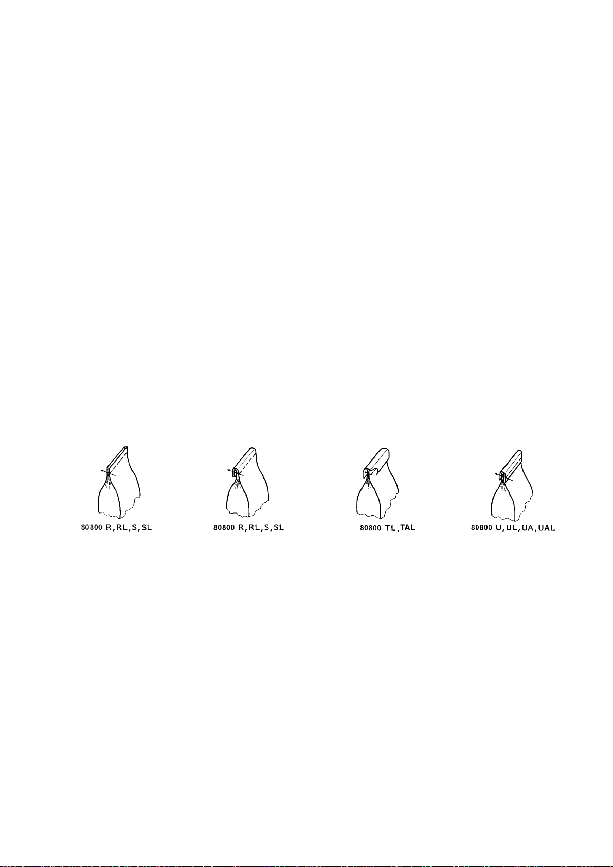
TYPES OF BAG CLOSURES
DIFERENTES MANERAS DE CERRAR LOS SACOS
* according to ISO 4916 and 4915
** according to FED. STD. No. 751a (USA)
* Según ISO 4916 y 4915
** Según Fed. Standard No. 751a (USA)
5
Page 6

SAFETY RULES
IINDICACIONES DE SEGURIDAD
1. Before putting the machine described in this manual into
service, carefully read the instructions. The starting of each
machine is only permitted after taking notice of the instructions
and by qualified operators.
IMPORTANT! Before putting the machine into service, also
read the safety rules and instructions from the motor supplier.
2. Observe the national safety rules valid for your country.
3. The sewing machine described in this instruction manual is
prohibited from being put into service until it has been ascertained that the sewing units which these sewing machines will
be built into, have conformed with the provisions of EC Machinery Directive 98/37/EC, Annex II B.
The machine is only allowed to be used as foreseen. The
foreseen use of the particular machine is described in paragraph STYLE OF MACHINE of this instruction manual. Another use, going beyond the description, is not as foreseen.
4. All safety devices must be in position when the machine
is ready for work or in operation. Operation of the machine
without the appertaining safety devices is prohibited.
5. Wear safety glasses.
6. In case of machine conversions and all valid safety rules must
be considered. Conversions and changes are made at your
own risk.
1. Antes de poner en marcha las maquinas descritas en este manual,
hay que leer cuidadosamente las instrucciones. El arranque de
cada maquina solamente se permite después de haber leído las
instrucciones y por personal calificado.
IMPORTANTE! También hay que leer las reglas de seguridad y
las instrucciones del fabricante del motor.
2. Observe las reglas nacionales de seguridad que rigen para su
país.
3. No se puede poner en marcha la maquina descrita en este manual
hasta que se confirme que la unidad de coser esta conforme con
el reglamento del Directivo de las Maquinas de la Comunidad
Europea 98/37/EC, Anexo II B.
La maquina solamente se puede utilizar para su uso previsto. El
uso previsto esta descrito en el capitulo ESTILO DE MAQUINAS
de este manual de instrucciones. Otro uso, diferente de la
descripción, no esta previsto.
4. Todos los dispositivos de seguridad tienen que estar en su sitio
cuando la maquina este lista para trabajar u operando. La operación
de la maquina sin los dispositivos de seguridad esta prohibida.
5. Utilice lentes de seguridad.
6. En el caso de una modificación de la maquina hay que tomar en
cuenta las reglas de seguridad. Modificaciones y cambios corren
por su riesgo.
7. Para las siguientes maniobras hay que desconectar la maquina del
suministro eléctrico apagando el interruptor principal o
desconectando el enchufe principal:
7. When doing the following machine has to be disconnected
from the power supply by turning off the main switch or by
pulling out the main plug.
7.1 When threading needle(s), looper, spreader
etc.
7.2 When replacing any parts such as needle(s),
presser foot, throat plate, looper, spreader,
feed dog, needle guard, folder, fabric guide
etc.
7.3 When leaving the workplace and when the
work place is unattended.
7.4 When doing maintenance work.
7.5 When using clutch motors without actuation
lock, wait until motor is stopped totally.
7.1 Enhebrando las agujas, looper, etc.
7.2 Reemplazando piezas como agujas, pie prensa tela, placa
de aguja, looper, diente de arrastre, guarda aguja, dobla dillador, etc.
7.3 Cuando salga de su puesto de trabajo y no se encuentre
nadie para atender la maquina.
7.4 Durante trabajos de mantenimiento.
7.5 Si esta utilizando motores de embrague, espere hasta que
el motor se detenga totalmente.
6
Page 7

8. Maintenance, repair and conversion work (see item 7) must
be done only by trained technicians or special skilled personnel under condsideration of the instructions.
Only genuine spare parts approved by Union Special have to
be used for repairs.
9. Any work on the electrical equipment must be done by an
electrician or under direction and supervision of special skilled personnel.
8. Mantenimiento, reparación y trabajos de conversión (vease
No. 7) solamente pueden ser efectuados por técnicos
entrenados o personal especializado bajo consideración de
las instrucciones.
Solamente repuestos originales y aprobados por Union
Special pueden ser utilizados para reparaciones.
9. Cualquier trabajo con el equipo eléctrico tiene que ser
ejecutado por un electricista o bajo la supervisión de personal
especialmente entrenado.
10. Work on parts and equipment under electrical power is not permitted.
Permissible exceptions are described in the applicable section of
standard sheet EN 50110 / VDE 0105.
11. Before doing maintenance and repair work on the pneumatic
equipment, the machine has to be discon- nected from the
compressed air supply. In case of existing residual air pressure after disconnecting from compressed air supply (e.g.
pneumatic equipment with air tank), the pressure has to be
removed by bleeding. Exceptions are only allowed for adjusting work and function checks done by special skilled personnel.
10. No esta permitido trabajar en piezas y equipos con la
electricidad conectada. Excepciones permitidas están
descritas en EN 50110 / VDE 0105.
11. Antes de hacer mantenimiento o reparaciones del equipo
neumático, hay que desconectar la maquina de la alimentación
del aire comprimido. En el caso que exista una presión de aire
residual después de desconectar la maquina (por ejemplo
equipos con tanques de aire), la presión tiene que ser
eliminada abriendo las válvulas. Excepciones están solamente
permitidas para trabajos de ajuste y revisión de funciones
por personal especialmente entrenado.
7
Page 8
NOISE EMISSION
EMISION DE RUIDO
Equivalent continuous A-weighted sound pressure
level (L
10821-CB-M1 at 1400 RPM and 50 % duty cycle.
) at workstation: 81 dB(A) according to ISO
pAd
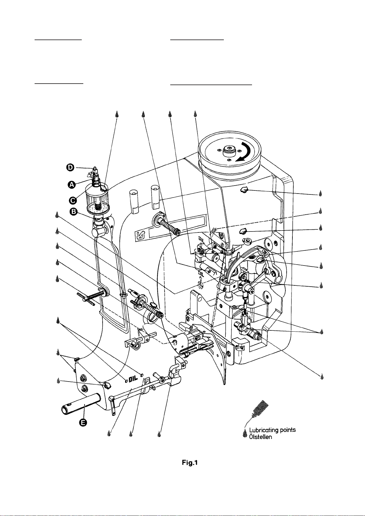
OILING DIAGRAM
Nivel de la intensidad del sonido en la estación del trabajo: 81
dB (A) segun ISO 10821-CB-M1 con 1400 revoluciones y 50%
del ciclo del trabajo.
DIAGRAMA DE LUBRICACION
8
Page 9

LUBRICATION AND OPERATION
LUBRICACION Y OPERACIÓN
The machines of class 80800 have to be cleaned and lubricated
twice a day before the morning and afternoon start on the lubricating
points indicated on the oiling diagram (Fig. 1). The sight feed oiler
has to be kept filled and should be adjusted so that it feeds two to
three drops of oil per minute. The oiler has to be refilled latest, when
2/3 of the oil is used up.
For lubrication we recommend "Mobil Oil DTE Medium" or
equivalent, which can be purchased from UNION SPECIAL
CORPORATION in 1/2 liter containers under part number G28604L,
or in 5 liter containers under part no. G28604L-5.
Before operating a new machine for the first time, the needle bar
guard (E, Fig. 1) and the sight feed oiler, which come with the
accessories of the machine, have to be screwed in. The sight feed
oiler has to be adjusted. All lubricating points, indicated on the oiling
diagram (Fig. 1), have to be oiled.
For adjusting fill the sight feed oiler half-way with oil and turn the
metering pin (A, Fig. 1) a little bit out and then turn it in, until there
will flow approx. two drops of oil per minute. This can be checked
on the sight glass (B, Fig. 1). Secure the setting of the metering pin
with lock nut (C, Fig. 1). Fill the oiler.
Repeat the oiling of a new machine after 10 minutes of operation!
When the machine is out of operation, the oil flow can be stopped
by tilting the lever (D, Fig. 1) on the sight feed oiler.
IMPORTANT! The oil flow has to be switched on again before
operating the machine.
NEEDLES
Each needle has both a type and size number. The type number
denotes the kind of shank, point, length, groove, finish and other
details. The size number , stamped on the needle shank, denotes
largest diameter of blade, measured in hundredths of a millimeter
respectively in thousandths of an inch, midway between shank and
eye. Collectively, type and size number represent the complete
symbol, which is given on the label of all needles packaged and
sold by UNION SPECIAL.
The standard needle for machines covered in this manual is
9848G250/100.
For closing bags made of plastic or woven polypropylene tapes it is
recommended to use needle type 9856T with teflon coating.
Below are the descriptions and available sizes:
Type No. Description and sizes
9848G Round shank, square point, double groove,
spotted, chromium plated.
Sizes available: 150/060, 170/067, 200/080,
250/100, 300/120, 400/156.
9856T Round shank, round point, double groove,
spotted, teflon-coated.
Sizes available: 200/080, 250/100.
Selection of proper needle size is determined by size of thread used.
Thread should pass freely through needle eye in order to produce a
good stitch formation.
To have needle orders promptly and accurately filled, an empty
package, a sample needle or type and size number should be
forwarded. Use description on label. A complete order would read:
"100 needles, Type 9848G, Size 250/100".
Las maquinas de la clase 80800 tienen que ser limpiadas y lubricadas
dos veces al día antes del turno de la mañana y de la tarde en los
puntos de lubricación indicados en el diagrama de lubricación (Fig. 1).
El deposito del aceite hay que mantener lleno y debe estar ajustado
para que suelte dos a tres gotas de aceite por minuto. El deposito de
aceite debe ser rellenado cuando 2/3 del aceite fue gastado.
Para la lubricación recomendamos „Mobil Oil DTE Medium“ o su
equivalente, que puede ser adquirido de UNION SPECIAL
CORPORATION en envases de ½ litro bajo el P/P No. G28604L, o en
envases de 5 litros bajo el P/P No. G28604L-5.
Antes de operar la maquina por la primera vez, el protector de la barra
de la aguja (E, Fig. 1) y el deposito del aceite, que están en los
accesorios de la maquina, tienen que ser fijados en la maquina. El
deposito de aceite tiene que ser ajustado. Todos los puntos de
lubricación, indicados en el diagrama de lubricación (Fig. 1) hay que
lubricarlos.
Para el ajuste llene el deposito hasta la mitad con aceite y ajuste el
pasador de medición (A, Fig. 1) hasta que salgan aprox. dos gotas de
aceite por minuto. Esto puede ser revisado en el visor (B, Fig. 1).
Asegure la posición del pasador de medición con la tuerca (C, Fig. 1).
Llene el deposito con aceite.
Repita la lubricación de una nueva maquina después de 10 minutos de
operación!.
Cuando la maquina no esta operando, se para el flujo del aceite doblando
la palanca (D, Fig. 1) del deposito.
IMPORTANTE: Acuérdese de activar el flujo del aceite otra vez antes
de arrancar la maquina.
AGUJAS
Cada aguja tiene un numero del tipo y del grosor. El numero del tipo
determina el cabo, la punta, el largo, la ranura, la determinación y otros
detalles. El numero del grosor, troquelado en el cabo de la aguja,
significa el diámetro máximo de la aguja, expresado en centésimos de
un milímetro o milésimos de pulgada, entre el cabo y el ojo de la aguja.
En conjunto los números del tipo y del grosor representan el símbolo
completo, que aparece en la etiqueta de los empaques de las agujas,
que vende UNION SPECIAL.
La aguja común para las maquinas de este manual es la 9848G250/
100.
Para cerrar sacos de plástico o polipropileno tejido se recomienda el
uso de la aguja tipo 9856T con recubrimiento de teflon.
A continuación encuentra la descripción y los grosores disponibles::
Tipo numero: Descripción y grosores
9848G Cabo redondo, punta cortante, doble ranura,
cromado.
Grosores disponibles: 150/060, 170/067, 200/080,
250/100, 300/120, 400/156.
9856T Cabo Redondo, punta redonda, doble ranura,
recubrimiento de teflon.
Grosores disponibles: 200/080, 250/100.
La selección de la aguja apropiada esta determinada por el grosor del
hilo utilizado. El hilo debería pasar libremente por el ojo de la aguja,
para permitir una buena formación de la puntada.
Para asegurar que los pedidos de las agujas se cumplan rápido y
correctamente, se recomienda enviar un empaque vacío, una muestra
de una aguja o indicar los números del tipo o del grosor. Un pedido
completo seria: „100 agujas, tipo 9848G , grosor 250/100“.
THREADING
Thread machine as illustrated in Fig. 2.
When threading the looper, be sure the thread goes through the
front eyelets, over the take-up and through the back eyelet before
threading the looper.
ENHEBRAR
Enhebre la maquina como se demuestra en la Fig. 2.
Cuando enhebre el looper, asegúrese que el hilo pase por los ojetes
frontales, encima del alimentador y por el ojete trasero antes de pasarlo
por el looper.
9
Page 10

THREADING THE MACHINE
EINFÄDELN DER MASCHINE
ADJUSTING AND THREADING INSTRUCTION FOR THE
THREAD GUIDING PARTS
Proper adjustment of the thread guides and thread take-ups ensures a durable seam and consequently tight closure of the bags.
Needle Thread: Basic adjustment see Adjusting Instructions. Shift
needle thread take-up c (80865 MX) on support d(80865PX) as
well as needle thread guide e (80858AX) on the machine housing
for proper control of the needle thread. The above mentioned parts
should be adjusted so that the needle thread, when slung around
the looper blade, is controlled before the needle enters the thread
triangle.
Looper Thread: Shift looper thread guide f (80858BX2) so, that
depending on the stitch length a sufficient amount of looper thread
is available for setting the next stitch.
Important Note: The above needle thread take-ups cannot be used
on machines with long needle bar connection (e.g. 80659 or 29774D)
which should be exchanged against the short needle bar connection
80659B together with thread guide G334. The threaded hole required for mounting bracket 80865QX of needle thread take up support 80865PX will already be provided in all future machines.
FF
igig
. 2. 2
F
ig
. 2
FF
igig
. 2. 2
AJUSTE E INSTRUCCIONES P ARA LOS GUIA HILOS
El ajuste correcto de los guía hilos y de los alimentadores asegura
una costura duradera y por consiguiente un firme cierre de los sacos.
Hilo de la aguja: Vea el ajuste básico en Instrucciones de ajustes.
Mueva el alimentador del hilo de la aguja (1) (80865MX) en su
soporte (2) (80865PX) igual como el guía hilo (3) (80858AX) en la
carcasa para el control apropiado para el hilo de la aguja. Las piezas
antes mencionadas deberían ser ajustadas en tal manera para que
el lazo del hilo de la aguja que se forma alrededor del looper este
controlado antes de que la aguja entre en el triángulo.
Hilo del looper: Mueva el guía hilo del looper (4) (80858BX2) en tal
manera que dependiendo del largo de la puntada haya suficiente
hilo para la próxima puntada.
Nota Importante: Los alimentadores de hilo arriba mencionados no
se pueden utilizar en maquinas con una conexión larga de la barra
de la aguja (por ejemplo 80669 o 22774D) las cuales deberían ser
cambiadas por una conexión corta 80669B en conjunto con un guía
hilo G334. El hueco con rosca requerido para el soporte de montaje
80865QX del soporte del alimentador 80865PX se encontrara en
todas las futuras maquinas.
10
Page 11

ADJUSTING INSTRUCTIONS
INSTRUCCIONES DEL AJUSTE
NOTE: Instructions stating direction or location, such as right, left,
front or rear of machine, are given relative to mechanic's
position in front of the machine, when the machine is placed
on an adjusting table, with the pulley to the right and the needle
bar in vertical position. The pulley rotates clockwise, in
operating direction; when viewed from the right end of the
machine.
INSERTING THE NEEDLE
Before adjusting the machine, insert a new needle with the shank as
far as possible into the needle bar. The long needle groove must
point to the front (toward the operator). Tighten the needle clamp nut
securely. Use the single ended open jaw wrench p art No. 21388 from
the accessories of the machine.
SETTING THE LOOPER
Remove the presser foot, throat plate and feed dog and on styles
80800TL, TAL, U, UA, UL and UAL also the needle guard for
convenient access to the machine. On styles 80800R, RL, S and SL
loosen the screw (A, Fig. 3) in the feed bar (B) and push the feed bar
needle guard (C) to the rear to avoid its contacting the needle (D).
For the two thread double locked stitch styles 80800R, RL, TL, T AL,
U, UA, UL and UAL, set the looper connecting rod (E) so the distance
(X, Fig. 4) between the center lines of the two ball joints is 69.8 mm (2
3/4"). The dimension (X, Fig. 4) should be 68.3 mm ( 2 11/16) on the
single thread chain stitch styles 80800S and SL. For adjustment
loosen the two nuts (F , Fig. 3) and turn connecting rod (E) forward or
backward as required to obtain specified dimension, retighten nuts
(F).
NOTE: The left nut has a left hand thread.
Set the looper (G) so the distance from the centerl ine of the needle
(D) to the looper (G) is 8 mm (5/16") when the looper is at its farthest
position to the right. Looper gauge No. 21225-5/16 can be used
advantageously in making this adjustment. For adjustment loosen
screws (H) in the looper drive lever (J), reposition as required to obtain
specified dimension and retighten screws (H) assuring that all end
play is taken out of the looper drive lever rocker shaft. Check to insure
a clearance of approx. 1 mm (.040") between the point of the looper
and the bed end cover when the looper is at its extreme left position.
Should the looper strike the bed end cover, recheck the distance
between center lines of ball joints and the looper gauge distance as
described above.
Rotate the machine pulley in operating direction so that the looper
moves from right to left. The looper point should pass as close as
possible to the back of the needle without contacting 0.08 to 0.13 mm
(.003 to .005") clearance. For adjustment loosen screws (A, Fig. 4)
in the looper eccentric fork (B) and turn looper rocker shaft (C) on the
looper rocker forward or backward as required. Retighten screw (A).
NOTA: T odas las indicaciones como derecho, izquierdo, adelante o atrás,
se refieren a la posición del mecánico en frente de la maquina,
con la maquina puesta en una mesa de trabajo, con el volante a
la derecha y la barra de la aguja en posición vertical. El volante
gira en sentido de reloj para la operación, desde el punto de vista
del lado derecho de la maquina.
INSERTAR LA AGUJA
Antes de ajustar la maquina debe insertar una nueva aguja con el cabo
de la aguja en la barra de la aguja. Las ranuras de las agujas deben
estar hacia adelante (hacia el operador). Apriéte la tuerca que fija la
aguja firmemente. Utilíze la llave P/P No. 21388 de los accesorios de la
maquina.
AJUSTE DEL LOOPER
Quite el pie prensa tela, la placa de la aguja y el diente de arrastre y en
las maquinas 80800TL, TAL, UA, UL y UAL t ambién el guarda aguja
para tener mejor acceso a la maquina. En los estilos 80800R, RL, S, y
SL suelte el tornillo (A, Fig.3) en la barra de alimentación B y mueva el
guarda aguja (C) en la barra de alimentación hacia atrás para evitar
que tenga contacto con la aguja (D).
Para las maquinas de dos hilos como 80800R, RL, TL, T AL, U, UA, UL
y UAL ajuste la barra del looper (E) para que la distancia (X, Fig. 4)
entre los centros de las junturas tenga una distancia de 69,8 mm (2 3/
4"). Esta distancia (X, Fig. 4) debería ser 68,3 mm (2 11/16) en las
maquinas de un solo hilo 80800 S y SL. Para ajustarlo suelte las dos
tuercas (F , Fig. 3) y gire la barra (E) hacia adelante o hacia atrás para
conseguir la distancia requerida. Apriete nuevamente las tuercas (F).
NOTA: La tuerca izquierda tiene una rosca izquierda.
Ponga el looper (G) de manera tal que la distancia entre el medio de la
aguja (D) al looper (G) sea de 8 mm (5/16) cuando el looper se
encuentre en su posición a la extrema derecha. El calibrador P/P No.
21225-5/16 puede ser utilizado para un ajuste preliminar. Para ajust ar
suelte los tornillos (H) en la palanca (J) del looper, mueva la p alanca
para obtener la distancia requerida y apriete los tornillos (H), asegurando
que la barra del accionamiento del looper no tenga juego. Asegure que
haya una distancia de aprox. 1 mm (.040") entre la punta del looper y la
tapa final de la maquina cuando el looper se encuentre en su posición
de la extrema izquierda. Si el looper tocaría la tapa, revise otra vez la
distancia entre los centros de las junturas y la distancia entre el looper
y la aguja como se ha descrito anteriormente.
Gire el volante en sentido de operación para que el looper se mueva
desde la derecha hacia la izquierda. La punta del looper debería pasar
muy cerca detrás de la aguja sin tocarla – distancia 0.08 a 0,13 mm
(.003 a .005"). Para lograr este ajuste debería soltar el tornillo (A, Fig.
4) en la horquilla excéntrica (B) del looper y girar el eje del looper (C)
hacia adelante o hacia atrás. Apriete el tornillo (A) otra vez.
Fig. 3
11
Page 12
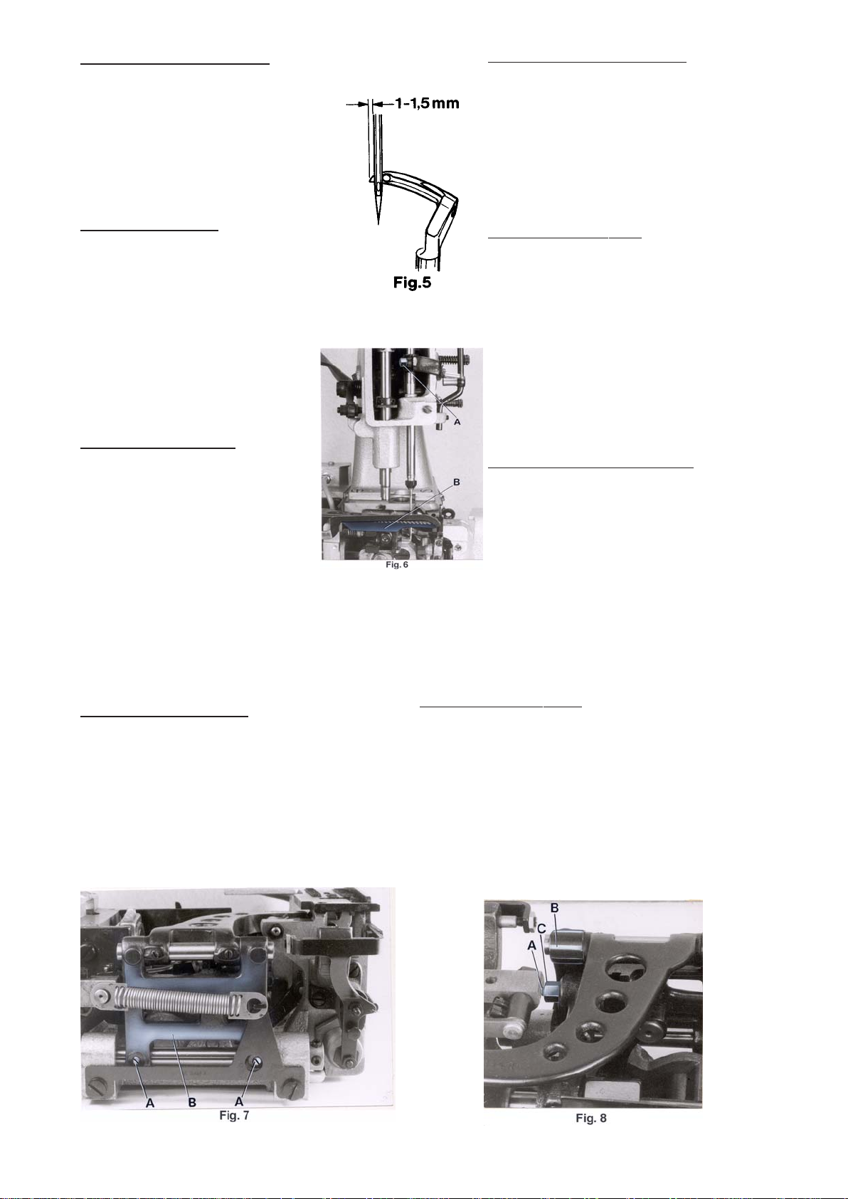
SETTING HEIGHT OF NEEDLE BAR
AJUSTE DE LA BARRA DE LA AGUJA
Remove the face cover on machine arm. Rotate
machine pulley in operating direction until the
looper point, moving to the left, projects 1 to 1.5
mm (.040" to .060") left of the needle (see Fig. 5).
Lower edge of looper and upper edge of needle
eye must be flush in this position. If adjustment is
necessary, loosen clamp screw (A, Fig. 6) in the
needle bar connection and move the needle bar
up or down, as required. Retighten screw (A) and
remount face cover.
SETTING THE FEED DOG
At highest point of feed dog travel, the feed dog
(B, Fig. 6) should be set so, that the rear teeth
project their full depth above the throat plate
surface. For setting remove the feed dog and
adjust the supporting screw (K, Fig. 3) on the top
of the feed bar to the required height. Remount
the feed dog, and on styles 80800TL, T AL, U, UA,
UL and UAL also the needle guard.
After loosening screws (A, Fig. 7) rear in the feed
rocker (B), the feed bar with feed dog can be
moved laterally to center the feed dog in the throat
plate slots, if required. Retighten screws (A).
CHANGING STITCH LENGTH
Remove the rear cloth plate. The length of the
stitch can be adjusted by raising or lowering the
stud (A, Fig. 8) in the segment slot of the feed
rocker (B). Lowering stud (A) will lengthen the
stitch, raising the stud will shorten the stitch. After loosening nut (C), stud (A) can be moved
accordingly. When the desired stitch length is
obtained, retighten nut (C) and remount cloth plate.
Remueva la tapa frontal en el brazo de la maquina.
Gire el volante de la maquina en sentido de operación
hasta que la punta del looper pase 1 a 1,5 mm (.040"
a .060") la aguja (vea Fig. 5). En esta posición el borde
inferior del looper tiene que encontrarse en el limite
superior del ojo de la aguja. Si se requiere ajuste,
suelte el tornillo (A, Fig. 6) en la conexión de la barra
de la aguja y mueva la barra hacia arriba o hacia abajo
como requerido. Apriete el tornillo (A) y ponga la tapa
frontal otra vez.
AJUSTE DEL ALIMENTADOR
En el punto mas alto del recorrido del alimentador,
los dientes del alimentador deberían sobrepasar la
placa de la aguja por la altura completa de los dientes.
Para lograr este ajuste remueva el alimentador y ajuste
el tornillo de soporte (K, Fig. 3) en la parte superior
de la barra de la alimentación a la altura requerida.
Monte el alimentador otra vez y en los estilos 80800TL,
TAL, U, UA, UL y UAL también el guarda aguja.
Después de haber soltado los tornillos (A, Fig. 7) en
el marco del transporte (B), la barra de alimentación
con el alimentador puede ser movido lateralmente para
centrar el alimentador en las ranuras de la placa de la
aguja, si haga falta. Apriete los tornillos (A).
AJUSTE DEL LARGO DE LA PUNT ADA
Remueva la tapa trasera. El largo de la puntada se
ajusta moviendo el perno (A, Fig. 8) en la ranura del
marco del alimentador (B). Bajando el perno (A) pone
la puntada mas larga y subiéndolo la pone mas corta.
Después de aflojar la tuerca (C), el perno (A) se deja
mover. Cuando se logra el largo de la puntada
deseado, hay que apretar la tuerca (C) otra vez y
montar la tapa trasera.
NOTE: Any change in stitch length will necessitate a
corresponding change in the needle guard
setting!
SETTING THE NEEDLE GUARD
The needle guard (C, Fig. 3) has to be set so, that it just contacts the
needle at its most forward point of travel, without deflecting it.
On styles 80800R, RL, S and SL loosen screw (A, Fig. 3) in the feed
bar (B) and adjust the needle guard (C) accordingly. Retighten screw
(A).
On styles 80800TL, TAL, U, UA, UL and UAL loosen the feed dog
fastening screw and move the needle guard accordingly. Retighten
screw and make sure that the feed dog rests on the supporting screw
in the feed bar.
NOT A: Después de cada cambio en el largo de la puntada, se debe
ajustar el guarda aguja!
AJUSTE DEL GUARDA AGUJA
Hay que ajustar el guarda aguja (C, Fig. 3) para que toque en su
movimiento hacia delante la aguja pero no la desvíe.
En los estilos 80800R, RL, S y SL suelte el tornillo (A, Fig. 3) en el
soporte del transportador (B) y ajuste el guarda aguja (C). Apriete
el tornillo (A) nuevamente.
En los estilos 80800TL, T AL, U, UA, UL y UAL suelte el tornillo que
fija el alimentador y mueva el guarda aguja. Apriete el tornillo otra
vez y asegúrese que el alimentador reposa en el tornillo de soporte
de la barra de la alimentación.
12
Page 13
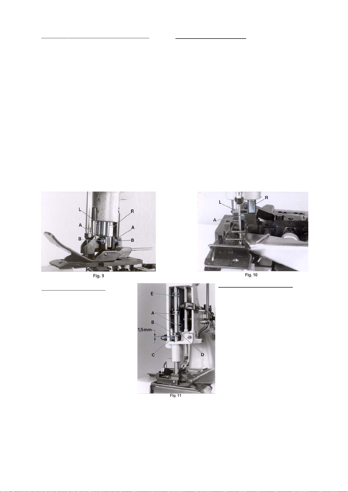
MOUNTING AND SETTING THE PRESSER FOOT
AJUSTE DEL PIE PRENSA TELA
Remove the needle and rotate the pulley until the feed dog is
below the throat plate. Depress the presser foot lifter lever and
insert the presser foot in the two presser bars (L and R, Fig. 9).
The right presser bar (R) should only engage with its pivot in the
groove of the presser foot shank.
Loosen the two lock nuts (A, Fig. 9) and align with the two set
screws (B) the needle slot in the presser foot with the needle
slot in the throat plate. Secure this setting with the two lock nuts
(A). Note: The two set screws (A) should just contact the pivot
of the right presser bar (R) but not be tightened. Now tighten the
two set screws left in the presser foot shank on the left presser
bar. Insert the needle.
Styles 80800TL, T AL, U, UA, UL and UAL have a two-piece presser foot. Insert the right presser foot part on the pivot of the right
presser bar (R, Fig. 10) and align the flats on the left presser bar
(L, Fig. 10) to the guide fork of the presser foot shank. The flats
on the left presser bar should slide freely in the fork, this can be
adjusted with screw (A). Secure this setting with the lock nut.
Now insert the left presser foot part on the pivot of the left presser bar (L) and align it with needle slot and feeler slot to the
throat plate. Tighten set screws in both presser foot shanks.
Remueva la aguja y gire el volante hasta que el alimentador se encuentre
debajo de la placa de la aguja. Apriete la palanca levantadora del pie e
inserte el pie en las barras (L y R, Fig. 9). La barra derecha (R) debería
entrar solamente con el pivote en la apertura del pie.
Afloje las dos tuercas (A, Fig. 9) y alinee con los dos tornillos (B) la ranura
para la aguja en el pie con la ranura para la aguja en la placa de la aguja.
Asegure este ajuste con los dos tornillos (A). Nota: Los dos tornillos (A)
deberían tocar solamente el pivote de la barra de presión derecha (R)
pero no apretarla. Ahora apriete los dos tornillos al lado izquierdo del tronco
del pie de la barra de presión izquierda. Inserte la aguja otra vez.
Los estilos 80800TL, T AL, U, UA, UL y UAL tienen un pie de dos piezas.
Inserte la parte derecha de pie en el pivote de la barra de presión derecha
(R, Fig. 10) y alinee las partes planas de la barra de presión izquierda (L,
Fig. 10) con la horquilla del tronco del pie. Las partes planas de la barra de
presión izquierda deberían deslizarse libremente en la horquilla, este ajuste
se logra con el tornillo (A). Asegure este ajuste con la tuerca. Ahora inserte
la parte izquierda del pie en el pivote de la barra de presión izquierda (L) y
alinee lo con la ranura para la aguja y la ranura del palpador en la placa de
la aguja. Apriete los tornillos en ambas partes del pie.
PRESSER FOOT PRESSURE
Rotate the pulley until the feed dog is below the
throat plate. Remove the face cover left on
machine arm and turn out the T-screw (H, Fig.
12) on the top of the machine arm, until it does
not excert any pressure on the leaf springs. In
this position, the pressure excerted on the presser foot, should be just strong enough to keep it
flat on the throat plate. By relocating the collars
(A, Fig. 11), which serve as a leaf spring rest,
on the left and right presser bar, the pressure
can be changed. Raising the collars increases
the pressure, lowering the collars decreases the
pressure.
On styles 80800TL and TAL the collar for the
leaf springs on the right presser bar is pressed
up slightly more when setting, than the collar on
the left presser bar, so that the pressure
excerted on the right presser foot part is slightly
higher than the pressure on the left presser foot
part.
Set the presser bar lifter collar (B, Fig. 11) on the lef t presser
bar so, that there is a distance of approx. 1.5 mm (1/16") between
lifter lever stud (C) and lower surface of the lifter collar (B), when
the presser foot rests on the throat plate (see Fig. 11). Set the
collar (D) on the right presser bar close to the fork of the presser bar lifter collar (C) on the left presser bar.
AJUSTE DE LA PRESION DEL PIE
Gire el volante hasta que los dientes del transportador
se encuentren debajo de la placa de la aguja.
Remueva la tapa frontal en el brazo y afloje el tornillo
(H, Fig.12) en la parte superior de la maquina hasta
que no haya mas presión en las ballestas. En esta
posición la presión al pie es solamente para
mantenerlo plano en la placa de la aguja. Moviendo
los anillos (A, Fig. 11), que sirven como soporte para
las ballestas, en la barra de presión izquierda y
derecha, se puede modificar la presión. Subiendo
los anillos aumenta la presión, bajando los anillos
disminuye la presión.
En las maquinas 80800TL y TAL el anillo para las
ballestas en la barra de presión derecha se encuentra
un poco encima del anillo en la barra de presión
izquierda, así que la presión que se ejerce a la parte
derecha del pie es un poco mayor que la presión de
la parte izquierda del pie.
Coloque el anillo (B, Fig. 11) para levantar la barra de presión en la
barra izquierda en tal manera para que haya una distancia de aprox. 1.5
mm (1/16") entre el perno levantador (C) y la superficie inferior del anillo
(B), cuando el pie reposa en la placa de aguja (vea Fig. 11). Coloque
el anillo (D) en la barra derecha cerca a la horquilla del anillo (C)
para levantar la barra de presión de la barra izquierda.
13
Page 14
PRESSURE FOOT PRESSURE (continued)
AJUSTE DE LA PRESION DEL PIE (continuación)
On styles 80800TL and TAL set the collar (D, Fig. 11) on the
right presser bar approx. 2.5 mm (7/64") above the fork of the
presser bar lifter collar (B). This effects, when lifting the presser foot, that the left presser foot part is lifted first by approx. 2.5
mm (7/64"), before the right presser foot part will lift too.
The presser foot lift is limited with the upper stop collar (E, Fig.
11) on the left presser bar. When the needle is in its lowest
position and the presser foot is lifted with presser foot bottom
tilted up, the needle bar respectively needle clamp nut should
not contact the presser foot bottom. Set collar (E) accordingly.
Now turn in T-screw (H, Fig. 12) until the necessary presser
foot pressure for proper feeding is excerted (determine by sewing
tests). Secure this setting with the knurled nut (J), which
simultaneously fastens the upper arm cover. Remount the face
cover.
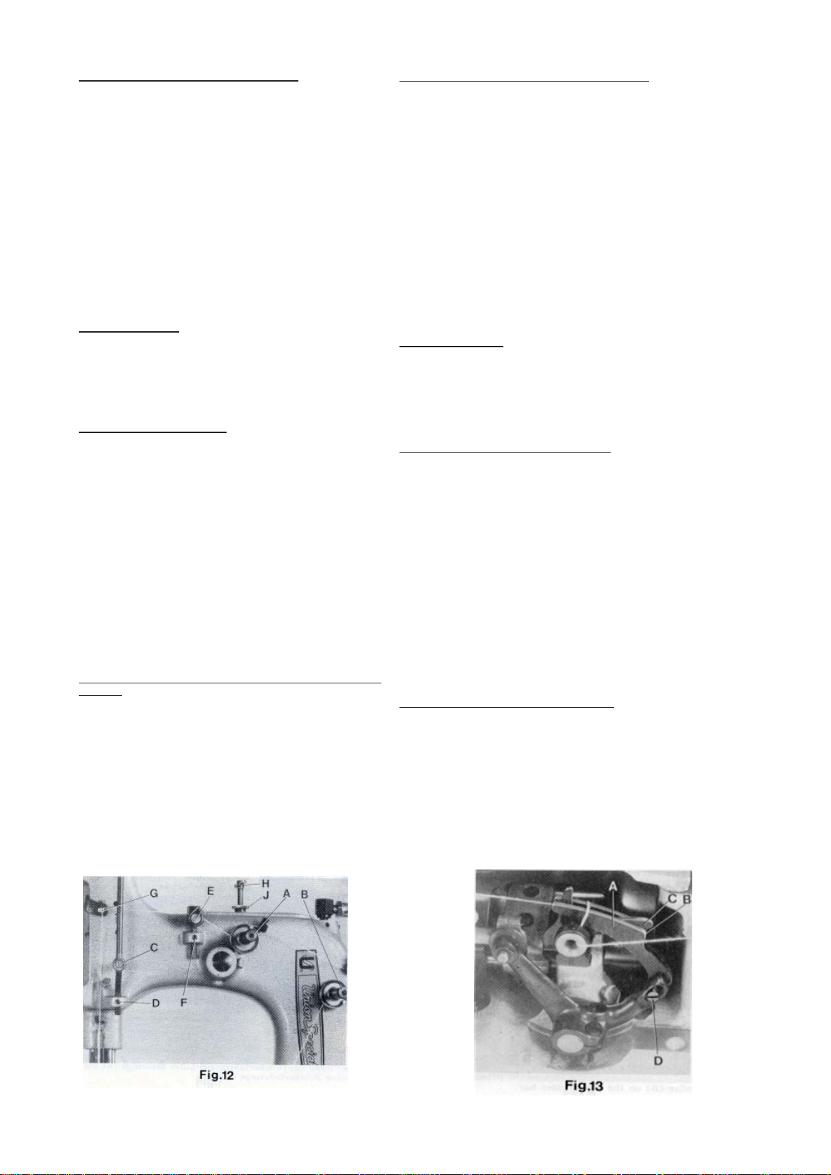
THREAD TENSION
The tension (A, Fig. 12) on the needle thread should be fairly
strong to produce uniform stitches. On the two thread double
locked stitch styles the tension (B) on the looper thread should
be barely sufficient to steady it.
LOOPER THREAD TAKE-UP
On the two thread double locked stitch styles, the height of the
looper thread take-up (A, Fig. 13) is set so, that the cast-off
hook (C) forces the looper thread over the corner (B) of the
looper thread take-up (A) at the time the point of the descending
needle is flush with the lower edge at looper or projects up to 1
mm (.040") below the lower edge of looper.
Draw the looper thread into the machine, rotate pulley in operating
direction and note the position of the needle point to lower edge
of looper at the time the cast-off (C) forces the looper thread
over the corner (B).
For setting the looper thread take-up loosen screw (D, Fig. 13).
When needle point is positioned above the lower edge of looper,
the looper thread take-up (A) has to be raised accordingly . When
the needle point is positioned more than 1 mm (.040") below the
lower edge of looper, the looper thread take-up (A) has to be
lowered accordingly. Retighten screw (D).
SETTING NEEDLE THREAD TAKE-UP ROLLER AND
EYELET
On the two thread double locked stitch styles 80800R, RL, TL,
TAL, U, UA, UL and UAL, the height of the needle thread takeup roller (C, Fig. 12) is set so, that the needle thread on the
downstroke of the needle just contacts the roll at the time the
needle thread loop is released from the looper. Loosen screw
(D) and set the needle thread take-up roller accordingly.
Retighten screw (D).
En las maquinas 80800TL y TAL coloque el anillo (D, Fig. 11) en la
barra de presión derecha aprox. 2,5 mm (7/64") encima de la horquilla
del anillo(B) de la barra de presión izquierda. De esto resulta que,
cuando se levante el pie, la parte izquierda del pie este levantado
primero por 2,5 mm (7/64") antes de que la parte derecha del pie se
levante también.
La altura del levantamiento del pie esta limitado por el anillo de parada
(E, Fig. 11) en la barra de presión izquierda. Cuando la aguja este en
su posición mas baja y el pie este levantado e inclinado hacia arriba,
la barra de la aguja o la tuerca que fija la guía no deberían tocar la
parte inferior del pie. Coloque el anillo (E) adecuadamente.
Ahora ajuste el tornillo con forma de „T“ (H, Fig. 12), para conseguir la
presión necesaria para una alimentación optima (determine esto con
pruebas de costura). Asegure este ajuste con la tuerca (J), que al
mismo tiempo fija la tapa superior del brazo. Coloque otra vez la tapa
frontal.
TENSION DEL HILO
El tensor (A, Fig. 12) del hilo de la aguja debería ser ajustado de tal
manera que la tensión del hilo de la aguja produzca unas puntadas
uniformes. En los estilos con costura de doble cadeneta de dos hilos,
el tensor (B) debe ser ajustado apenas lo suficiente para mantener la
costura.
ALIMENTACION DEL HILO DEL LOOPER
En las maquinas de costura de doble cadeneta de dos hilos, se ajusta
la altura del alimentador del hilo del looper (A, Fig. 13) en tal manera
para que el gancho (C) del alimentador del hilo del looper suelte el hilo
sobre el canto (B) del alimentador (A) en el momento cuando la punta
de la aguja coincida con el borde inferior del looper o pase hasta 1 mm
(.040") debajo el borde inferior del borde del looper. Enhebre el hilo
del looper, gire el volante en sentido de operación y memorice la
posición de la punta de la aguja referente al looper en el momento
cuando el gancho del alimentador (C) suelte el hilo sobre el canto (B).
Para ajustar el alimentador del hilo del looper suelte el tornillo (D, Fig.
13). Si la punta de la aguja se encuentra por encima del borde inferior del looper, hay que ajustar el alimentador (A) hacia arriba. Si la
punta de la aguja se encuentra más que 1 mm por debajo del borde
inferior del looper, hay que bajar el alimentador (A) adecuadamente.
Apriete el tornillo (D) otra vez.
ALIMENTACION DEL HILO DE LA AGUJA
En las maquinas de costura de doble cadeneta 80800R, RL, TL, T AL,
U, UA, UL y UAL, la altura del rodillo (C, Fig. 12) del alimentador del
hilo de la aguja esta fijado de manera tal, que el hilo durante el
movimiento de la aguja hacia abajo solamente toque el rodillo en el
mismo momento cuando el looper suelte el lazo del hilo de la aguja.
Suelte el tornillo (D) y ajuste el rodillo del alimentador del hilo de la
aguja adecuadamente. Apriete el tornillo (D) otra vez.
14
Page 15

SETTING NEEDLE THREAD TAKE-UP ROLLER AND EYELET
continued
On the single thread chain stitch styles 80800S and SL, the needle
thread take-up roller (C) should be positioned so as not to contact
the needle thread at any time.
On all styles the eyelet (E, Fig. 12) should be positioned so, that
the needle thread runs nearly horizontal, parallel to cloth plate,
between eyelet (G) on needle bar connection and eyelet (E) on
machine arm, when the needle is in its upmost position. Eyelet
(E) is secured by screw (F).
MOUNTING THE PROXIMITY SWITCH FOR FEELER
Remove cloth plate and left end cover. Mount the electronic
proximity switch (A, Fig. 14) to the dimension of 28 mm (1.1"), as
shown in Fig. 14.
NOTE: Be careful when tightening the two plastic nuts (B) in
order not to damage the switch.
The electronic proximity switch (A) is short circuit proof! It is
connected according to wiring diagrams Fig. 26 for styles
80800R, S, U and UA and Fig. 27 for styles 80800RL, SL, TL,
TAL, UL and UAL.
MOUNTING AND SETTING THE FEELER
The feeler (D, Figs. 14 and 15) is adjusted initially with the two
fastening screws (C, Fig. 14) for the feeler support bracket.
The feeler (D, Figs. 14 and 15) should not have any lateral play
but should turn readily. For this, adjust the centering shaft (E,
Fig. 15) with centering screw (F) and lock nut (G) accordingly.
Loosen screw (H, Fig. 15) and center the feeler (D) in the throat
plate and presser foot slot, by moving the centering shaft (E)
laterally. The feeler must turn readily . Retighten screw (H).
Hang in tension spring (J, Fig. 14).
The feeler should be set as high as possible. The dimension (X,
Fig. 14) between upper throat plate surface and upper edge of
feeler at the bag entrance zone, should not be less than 7 mm
(.270") on styles 80800R, RL, S and SL, and not less than 7 mm
(.290") on styles 80800TL, TAL, U, UA, UL and UAL.
For adjustment loosen nut (K, Fig. 14) and turn-off screw (L), so
that the head of screw does not contact the magnet in the feeler
support bracket. Loosen nut (M) and turn the feeler stop screw
(N) in or out, as required, to adjust the correct feeler height.
NOTE: When the presser foot rests on the throat plate (feed dog
below throat plate), the distance between upper edge of feeler
and lower edge of the feeler slot cut-out in the presser foot (see
Y, Fig. 14) should be approx. 1 mm (.040") on styles 80800R,
RL, S and SL, and approx. 2 mm (.080") on styles 80800TL,
TAL, U, UA, UL and UAL.
Secure the set feeler height with lock nut (M, Fig. 14).
ALIMENTACION DEL HILO DE LA AGUJA (continuación)
En las maquinas de cadeneta simple 80800S y SL el rodillo (C) del
alimentador del hilo de la aguja debe ser colocado de forma que nunca
toque el hilo.
En todos los estilos el ojete (E, Fig. 12) debería ser puesto para que el
hilo de la aguja se mueva casi en forma horizontal, paralelamente a la
tapa principal de la maquina, entre el ojete (G) en la conexión de la barra
de la aguja y el ojete (E) en el brazo de la maquina, cuando la aguja se
encuentre en su posición mas alta. Asegure el ojete (E) con el tornillo (F).
COLOCACION DEL INTERRUPTOR DE APROXIMACION
Remueva la tapa principal y la tapa final izquierda. Coloque el interruptor
de aproximación (A, Fig.14) en una distancia de 28 mm (1.1") como se
demuestra en la Fig. 14.
NOTA: Apriete las dos tuercas plásticas (B) cuidadosamente para no
dañar el interruptor.
El interruptor de aproximación esta a prueba de corto circuito! El esta
conectado de acuerdo al diagrama de la Fig. 26 para maquinas del estilo
80800R, S, U, y UA y al diagrama de la Fig. 27 p ara maquinas del estilo
80800RL, SL, TL, T AL, UL y UAL.
AJUSTE DEL PALPADOR
El palpador (D, Figs. 14 y 15) esta fijado inicialmente con dos tornillos (C,
Fig. 14) a su soporte. El palpador (D, Figs. 14 y 15) no puede tener juego
lateral, pero debe girar libremente. Para esto ajuste adecuadamente el
eje central (E, Fig. 15) con el tornillo para centrar (F) y la contra-tuerca
(G).
Suelte el tornillo (H, Fig. 15) y centre el palpador ( D) en las ranuras de la
placa de aguja y del pie moviendo el eje central (E) lateralmente. El
palpador debe girar libremente. Apriete el tornillo (H) otra vez.
Coloque el resorte (J Fig. 14).
El palpador tiene que ser colocado tan alto como sea posible. La distancia
(X, Fig. 14) entre la superficie superior de la placa de la aguja y el borde
superior del palpador en la parte donde entra el saco no debería ser menor
a una distancia de 7 mm (.270") para maquinas 80800R, RL, S y SL y no
menor a 7,5 mm (290") parta maquinas 80800 TL,TAL, U, UA, UL y
UAL.
Para este ajuste suelte la tuerca (K, Fig. 14) y gire el tornillo (L) tanto
hacia atrás hasta que la cabeza del tornillo no pueda tocar más el imán
en el perno fijador del imán. Suelte la tuerca (M) y gire el tornillo tope del
palpador (N) adecuadamente hasta que logre la altura correcta del
palpador.
NOTA: Cuando el pie prensa-tela reposa en la placa de la aguja (con el
transportador debajo de la placa de la aguja), debería haber una distancia
de aprox. 1 mm (.040") para maquinas 80800R,RL,S y SL y aprox. 2 mm
(.080") para maquinas 80800TL, TAL,U ,UA, UL y UAL entre el borde
superior del palpador y el borde inferior del sacado para el palpador en el
pie prensa-tela (vea Y Fig. 14).
Asegure la altura del palpador con la contra-tuerca (M, Fig. 14).
15
Page 16

SETTING THE SWITCHING PRESSURE
AJUSTE DE LA PRESIÓN DEL INTERRUPTOR EN EL PALPADOR
The switching pressure on the feeler is set with screw (K, Fig.
14).
Turn screw (K) slowly towards the magnet in the feeler support
bracket, until its head just contacts the magnet, then turn it back
1/2 turn, so that the feeler moves freely and the screw head is
within the range of influence of the magnet.
NOTE: The closer the head of screw (K, Fig. 14) to the magnet
the higher the switching pressure on the feeler. Secure the
position of screw (K) with lock nut (L).
SETTING THE SWITCHING POINT
The electrical switching point of the proximity switch (A, Fig. 14)
is determined by screw (Q, Fig. 14). The distance between screw
head and the face of the proximity switch is approx. 4 mm (5/
32") (see Fig. 14), when the feeler is in home position. This
distance of 4 mm (5/32") is not exactly the same for all switches.
Connect the machine electrically . With feeler in home position
set the proper switching point as follows:
Loosen nut (P , Fig. 14). Turn screw (Q) away from switch, until
the switch switches on. Then turn screw (Q) slowly towards the
switch, until the switch switches off. Now turn screw (Q) a further 1/2 turn towards the switch. Secure this position of screw
(Q) with lock nut (P).
SETTING THE CHAIN CUTTER ON STYLES 80800R, RL, S
AND SL
When the solenoid on styles 80800R and S or the air cylinder on
styles 80800RL and SL for the chain cutter (S, Fig. 15) is not
activated and the chain cutter is in its home position below the
throat plate, the knife tips of the chain cutter (S) should be
positioned 0.5 mm (.020") below the throat plate top surface.
T o obtain this setting, adjust the knife lever stop screw with lock
nut (T , Fig. 15) in the bottom of the bed casting accordingly . The
slotted thread end of screw (T) is accessible from the bottom of
the bed casting for adjustment.
In cutting position, above the throat plate, the cutting edges of
the chain cutter (S, Fig. 15) should overlap by 0.3 mm (.012") to
assure a proper thread chain cutting.
When the chain cutter is in its home position, set the stud (A,
Fig. 17A) so, that the head of stud just contacts the holder (B)
but does not bind. After loosening screws (C) the stud can be
set accordingly. Retighten screws (C) on the flat of stud (A).
On styles 80800R and S with solenoid operated chain cutter the
core of solenoid (C, Fig. 16) must rest firmly on the solenoid (D)
while adjusting the overlapping of the knife cutting edges of the
chain cutter. Unhook pull-back spring (R, Fig. 15) and press the
solenoid rod against the solenoid until the core of solenoid (C,
Fig. 16) butts on the solenoid (D). Loosen nut (A, Fig. 16) and
move clamp (B) on the solenoid rod to the left or right, until the
cutting edges overlap approx. 0.3 mm (.012"). Retighten nut (A)
and replace pull-back spring (R, Fig. 15).
NOTE: A metallic sound must be heard on the solenoid when it
is energized.
La presión del interruptor en el palpador se ajusta con el tornillo (K, Fig.
14).
Gire el tornillo (K) suavemente contra el imán en el perno fijador hasta
que la cabeza del tornillo toque el imán. Después gire el tornillo 1/2 de
vuelta hacia atrás, para que el palpador gire todavía libremente y la
cabeza del tornillo sigue todavía bajo la influencia del imán.
NOTA: Cuánto más cerca se encuentre la cabeza del tornillo (K, Fig.
14) al imán, tanto mayor es la presión del interruptor en el palpador.
Asegure la posición del tornillo (K) con la contra-tuerca (L).
AJUSTE DEL PUNTO DE ACTIVACIÓN DEL INTERRUPTOR
El punto de activación del interruptor de aproximación (A Fig. 14) esta
determinado con el tornillo (Q, Fig. 14). La distancia entre la cabeza del
tornillo y el frente del interruptor es de aprox. 4 mm (5/32") ( vea Fig. 14)
cuando el palpador esta en su posición básica . Esta distancia no es
exactamente igual para todos los interruptores. Conecte la máquina
eléctricamente. El punto exacto de la activación se ajusta de la siguiente
manera:Suelte la tuerca (P, Fig. 14). Gire el tornillo (Q) alejándolo del
interruptor hasta que el interruptor se active. Después gire el tornillo (Q)
hacia el interruptor hasta que el interruptor se apague. Después gire el
tornillo (Q) ½ vuelta más en sentido hacia el interruptor. Asegure esta
posición del tornillo (Q) con la contra-tuerca (P).
AJUSTE DE LA TIJERA PARA CORTAR LA CADENETA EN
MAQUINAS 80800R, RL, S y SL
Cuando el solenoide en las maquinas 80800R y S y en las maquinas
80800RL y SL el cilindro neumático de la tijera (S, Fig. 15) para la
cadeneta no esté activado y la tijera esté en su posición básica debajo
de la placa de la aguja, los bordes superiores de las cuchillas de la tijera
deberían encontrarse aprox. 0,5 mm (.020") debajo de la placa de la
aguja.
Ajuste para esto el tornillo tope para la tijera con la contra tuerca (T , Fig.
15) en el fondo de la cama de la maquina. En posición de corte encima
de la placa de aguja, las cuchillas de la tijera (S, Fig. 15) deberían
solaparse aprox. 0,3 mm (.012") para asegurar un corte limpio de la
cadeneta.
Cuando la tijera esta en su posición básica, ajuste el perno (A, Fig. 17 A)
de manera tal que la cabeza del perno toque solamente el portador (B)
pero no se tranque. Después de soltar los tornillos (C) el perno se puede
ajustar adecuadamente. Apriete los tornillos (C) en la parte plana del
perno (A) otra vez.
En las maquinas 80800R y S con la tijera activada por solenoide, el
nucleo del solenoide (C, Fig. 16) tiene reposar firmemente contra el
solenoide mientras se ajuste el solapado de la hojas de la tijera. Suelte
el resorte (R, Fig. 15) y presione el perno del solenoide contra el solenoide
hasta que el nucleo del solenoide (C, Fig. 16) este plano con el solenoide
(D). Suelte la tuerca (A, Fig. 16) y mueva la abrazadera (B) en el perno
del solenoide hacia la izquierda o derecha, hasta que las hojas de la
tijera se solapan aprox. 0.3 mm (.012"). Apriete la tuerca (A) otra vez y
coloque el resorte (R, Fig.15).
NOTA: Cuando se activa el solenoide debería escucharse un sonido
metálico.
16
Page 17
SETTING THE CHAIN CUTTER ON STYLES 80800R, RL, S AND
SL (continued)
AJUSTE DE LA TIJERA PARA CORTAR LA CADENETA EN
MAQUINAS 80800R, RL y SL (continuacion)
On styles 80800RL and SL with electro-pneumatic operated chain
cutter, the cutting edges should overlap approx. 0.3 mm (.012"),
when clamp (A, Fig. 17), on the piston rod of the air cylinder butts
on the hexagon head stop screw (B).
For adjusting loosen lock nut (C, Fig. 17) and press clamp (A) against
the hexagon head stop screw (B). Now turn stop screw (B) in or
out, as required, until the cutting edges overlap approx. 0.3 mm
(.012"). Secure the setting of stop screw (B) with lock nut (C).
NOTE: The piston of the air cylinder should not strike against the
cylinder inside when actuated. The stroke of piston must be limited
by clamp (A, Fig. 17) striking against hexagon head stop screw (B).
Operating pressure of air cylinder: 3 to 4 bar (44 to 59 psi).
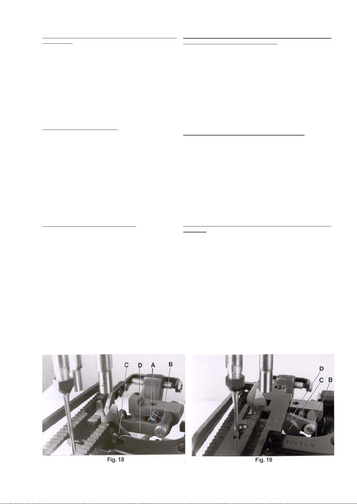
REPLACING THE CHAIN CUTTER
The knives of the chain cutter can not be changed individually, the
complete chain cutter part No. 80677R has to be replaced.
Remove presser foot, throat plate and cloth plate. Swing-off the
end dover. Turn pulley until the feed dog is in its extreme front
position. Loosen screws (A, Fig. 18) and pull the chain cutter with
stud (B) to the front and take it out of the machine.
Assemble the new chain cutter. Insert the hole on knife pilot (C, Fig.
18) down on the pin in the knee lever. Insert stud (B) in the hole on
knife pilot (D) and tighten screws (A) on the flat of the stud. Check
if the cutting edges overlap approx. 0.3 mm (.012").
Swing-in the end cover. Remount cloth plate, throat plate and presser foot.
RESHARPENING CHAIN CUTTER KNIVES
The knives of the chain cutter can be resharpened as long as the
cutting edges will overlap approx. 0,3 mm (.012") and the knife pilot
(D, Fig. 19) clears on the bottom surface of the throat plate when in
cutting position. The knife pilot (D) should not contact the bottom
surface of the throat plate, because the stroke of the chain cutter
must be limited on styles 80800R and S by the core of the solenoid
(C, Fig. 16) striking against the solenoid (D, Fig. 16) and on styles
80800RL and SL by the clamp (A, Fig. 17) striking against the
hexagon head stop screw (B, Fig. 17). The knife pilot (C, Fig. 19)
and head of stud (B, Fig. 19) should not contact, when in cutting
position.
En las maquina 80800RL y SL con un cort ador electro neumático, las
hojas de la tijera deberían solaparse aprox. 0.3 mm (.012"), cuando la
abrazadera (A, Fig. 17) en el perno del pistón de aire, choca contra el
tornillo tope hexagonal (B).
Para este ajuste suelte la contra-tuerca (C, Fig. 17) y presione la
abrazadera (A) contra el tornillo tope hexagonal (B). Gire ahora el tornillo
tope hexagonal (B) como fuera necesario, hasta que las cuchillas de la
tijera se están solapando aprox. 0,3 mm (.012"). Asegure el ajuste del
tornillo tope hexagonal (B) con la contra-tuerca (C).
NOTA: El pistón del cilindro neumático no debe chocar contra el cilindro
cuando se lo activa,. El recorrido del pistón tiene que ser limitado con
abrazadera (A, Fig. 17) que choca contra el tornillo tope hexagonal (B).
Presión operacional del cilindro neumático: 3 a 4 bar (44 a 59 psi).
CAMBIO DE LA TIJERA PARA CORTAR LA CADENETA
Las cuchillas de la tijera no pueden ser cambiadas individualmente.
Siempre hay que cambiar la tijera completa No. 80677R.
Remueva la tapa lateral izquierda, el pie prensa-tela y la placa de la
aguja. Gire el volante hasta que el transportador se encuentre en su
posición delantera. Suelte los tornillos (A, Fig. 18) y hale la tijera con el
perno (B) hacia adelante y remuévala de la máquina.
Coloque la tijera nueva. Inserte la ranura de la cuchilla trasera (C, Fig.
18) de la tijera en la clavija . Inserte el perno (B) en el hueco de la cuchilla
(D) y apriete los tornillos (A) en la parte plana del perno. Revise si las
cuchillas de la tijera se están solapando 0.3 mm (.012").
Coloque la placa de la aguja, el pie prensa-tela y la tapa lateral izquierda
otra vez.
AFILAR LAS CUCHILLAS DE LA TIJERA DEL CORTE DE LA
CADENTA
Las cuchillas de la tijera del corte de la cadeneta se puede afilar solamente
tantas veces hasta que las cuchillas se estén solapando 0,3 mm y la
cuchilla (D, Fig. 19) en posición de corte tenga suficiente espacio libre
en la superficie inferior de la placa de la aguja. La cuchilla (D) de la tijera
no debe tocar la superficie inferior de la placa de la aguja, porque el
recorrido de la tijera tiene que ser limitada en la maquinas 80800R y S
por la parte central del solenoide (C, Fig. 16) contra el solenoide (D, Fig.
16) y en las maquinas 80800RL y SL por la abrazadera (A, Fig. 17) que
choca contra el tornillo tope hexagonal (B, Fig. 17). La cuchilla (C, Fig.
19) y la cabeza del perno (B, Fig. 19) no deberían tocarse en posición de
corte.
17
Page 18
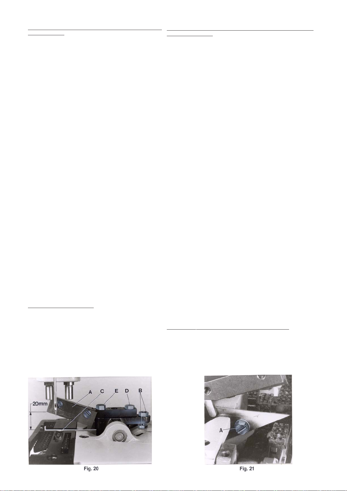
SETTING THE TAPE CUTTER ON STYLES 80800TL, TAL, U,
UA, UL AND UAL
When the solenoid on styles 80800U and UA or the air cylinder on
styles 80800TL, T AL, UL or UAL for the t ape cutter is not activated
and the upper knife (A, Fig. 20) is in its home position, the tip of the
cutting edge of upper knife should be positioned approx. 20 mm
(51/64") above the throat plate top surface (see Fig. 20).
To obtain this setting, adjust the stop screw with lock not (B, Fig.
20) in the knife holder lever accordingly.
The lower knife (C, Fig. 20) has to be set so, that its cutting edge is
flush with the throat plate top surface. The fastening screw is located
below the throat plate (See A, Fig. 21 for styles 80800U, UA, UL
and UAL and A, Fig. 22 for styles 80800TL and TAL). In cutting
position the cutting edges of upper and lower knife should overlap
approx. 0.3 mm (.012") to assure a proper tape and thread chain
cutting.
AJUSTE DEL CORTADOR DE CINTA EN LAS MAQUINAS 80800TL,
TAL, U, UA, UL Y UAL
Cuando el solenoide en las máquinas 80800U y UA o el cilindro neumático
en las maquinas 80800TL, UL o UAL para el cortador de cinta no esta
activado y la cuchilla superior (A, Fig. 20) esta en su posición básica, la
punta de la cuchilla superior debería encontrarse aprox. 20 mm (51/64")
por encima de la superficie de la placa de la aguja (vea Fig. 20).
Para conseguir esta distancia, ajuste el tornillo tope con la contra-tuerca
(B, Fig. 20) en el porta-cuchilla adecadamente.
La cuchilla inferior (C, Fig. 20) tiene que ser ajustada para que su borde
cortante este al ras con la superficie de la placa de la aguja. El tornillo
respectivo está ubicado debajo de la placa de la aguja ( vea A, Fig. 21 para
maquinas 80800U, UA, UL y UAL y A, Fig. 22 para maquinas 80800TL y
TAL). En posición de corte los bordes cort antes de la cuchilla superior e
inferior deberían solaparse aprox. 0.3 mm (.012") para asegurar un corte
limpio de la cinta y de la cadeneta de los hilos.
When the tape cutter is in its home position, set the stud (A, Fig.
17A) so, that the head of stud just contacts the holder (B) but does
not bind. After loosening screws (C) the stud can be set accordingly .
Retighten screws (C) on the flat of stud (B).
On styles 80800U and UA with solenoid operated taper cutter , the
core of solenoid (C, Fig. 16) must rest firmly on the solenoid (D,
Fig. 16) while adjusting the overlapping of the knife cutting edges of
the tape cutter. Unhook pull-back spring (R, Fig. 15) and press the
solenoid rod against the solenoid until the core of solenoid (C, Fig.
16) butts on the solenoid. Loosen nut (A, Fig. 16) and move clamp
(B, Fig. 16) on the solenoid rod to the left or right until the cutting
edges overlap approx. 0.3 mm (0.012 in.). Retighten nut (A) and
replace pull-back spring (R, Fig. 15).
NOTE: A metallic sound must be heard on the solenoid when it is
energized.
On styles 80800TL, TAL, UL und UAL with electro-pneumatic
operated tape cutter, the cutting edges of upper and lower knife
should overlap approx. 0.3 mm (.012"), when clamp (A, Fig. 17) on
the piston rod of the air cylinder butts on the hexagon head stop
screw (B).
For adjustment loosen lock nut (C, Fig. 17) and press clamp (A)
against the hexagon head stop screw (B). Now turn stop screw (B)
in or out, as required, until the cutting edges overlap approx. 0.3
mm (.012"). Secure the setting of stop screw (B) with lock nut (C).
NOTE: The piston of the air cylinder should not strike against the
cylinder inside when actuated. The stroke of piston must be limited
by clamp (A, Fig. 17) striking against hexagon head stop screw (B).
SETTING THE SHEAR ANGLE
After loosening screws (D and E, Fig. 20) the shear angle between
upper and lower knife of tape cutter can be adjusted by twisting the
upper knife holder. The shear angle should be kept as small as
possible, just so that the tape with thread chain will be cut properly .
Retighten screws (D and E).
Cuando el cortador este en su posición básica del corte, ponga el perno
(A, Fig. 17A) en tal manera, para que la cabeza del perno toque el soporte
(B), pero no lo tranque. Después de aflojar los tornillos (C), el perno puede
se colocado adecuadamente. Apriete los tornillos (C) otra vez en la parte
plana del perno (B)
En las maquinas 80800U y UA con cortador de cinta activado por solenoide,
el nucleo del solenoide (C, Fig. 16) tiene que reposar firmemente contra
el solenoide (D, Fig. 16) mientras se ajusta el solapado de las hojas
cortantes del cortador. Suelte el resorte (R, Fig. 15) y presione el perno
del solenoide contra el solenoide hasta que el nucleo del solenoide (C,
Fig. 16) reposa contra el solenoide. Suelte la tuerca (A, Fig. 16) y mueva
la abrazadera (B, Fig. 16) en el perno del solenoide hacia la izquierda o la
derecha hasta que los bordes cortantes del cortador se solapan aprox. 0.3
mm (0.012"). Apriete la tuerca (A) y coloque el resorte (R, Fig. 15) otra
vez.
NOTA: Cuando se activa el solenoide debería escucharse un sonido
metálico.
En las maquina 80800TL, T AL, UL y UAL con un cortador de cinta electro
neumático, la hoja superior e inferior del cortador deberían solaparse aprox.
0.3 mm (.012"), cuando la abrazadera (A, Fig. 17) en el perno del pistón
de aire, choca contra el tornillo tope hexagonal (B).
Para este ajuste suelte la contra-tuerca (C, Fig. 17) y presione la abrazadera
(A) contra el tornillo tope hexagonal (B). Gire ahora el tornillo tope hexagonal (B) como fuera necesario, hasta que las hojas del cortador se están
solapando aprox. 0,3 mm (.012"). Asegure el ajuste del tornillo tope hexagonal (B) con la contra-tuerca (C).
NOTA: El pistón del cilindro neumático no debe chocar contra el cilindro
cuando se lo activa,. El recorrido del pistón tiene que ser limitado con
abrazadera (A, Fig. 17) que choca contra el tornillo tope hexagonal (B).
AJUSTE DEL ANGULO DE LAS HOJAS DEL CORTADOR
Después de aflojar los tornillos (D y E, Fig. 20) el ángulo entre la hoja
superior e inferior del cortador se puede ajustar moviendo el porta cuchilla
superior. El ángulo de debería ser tan pequeño como posible, justamente
para que corte bien la cinta y la cadeneta de hilos. Apriete los tornillos (D
y E) otra vez.
18
Page 19

REPLACING THE TAPE CUTTER KNIVES
CAMBIO DE LAS CUCHILLAS DEL CORTADOR
Swing-off the end cover.
Remove the presser foot for replacing the upper knife on styles
80800U, UA, UL and UAL and for replacing the lower knife,
additionally the throat plate.
The upper knife on styles 80800TL and TAL can be replaced
directly. For replacing the lower knife remove both presser foot
parts, the throat plate and the cloth plate and loosen the cutter
plate.
Make sure, especially when mounting resharpened knives, that
the cutting edges overlap approx. 0.3 mm (.012") in cutting
position. Recheck the shear angle, if necessary.
Swing-in end cover and remount the parts removed.
TAPE FOLDER FOR STYLES 80800U AND UL
T ake out the tape folder with fastening parts from the machine
accessories and assemble it as shown on page 50. The folder
has to be aligned with the support rods to the top surface of
throat plate. The height should be adjusted so, that the tape fully
covers the bag opening and the seam is located in the lower
third of the tape (see Fig. 23).
The folder can be adjusted for tape widths from 50 to 70 mm (1
31/32 to 2 3/4"). Set the guides so, that the bag opening will be
equally bound.
Assemble the tape reel as shown on page 50.
Abra la tapa frontal.
Quite el pie para cambiar las cuchillas superiores en la maquinas 80800U,
UA, UL y UAL y para cambiar la cuchillas inferiores adicionalmente la
placa de la aguja.
La cuchilla superior en las máquinas 80800TL y T AL puede ser cambiada
directamente. Para cambiar la cuchilla inferior, remueva ambas partes
del pie, la placa de la aguja, la tapa principal y el soporte del cortador .
Asegúrese, especialmente con cuchillas afiladas recientemente, que los
bordes cortantes solapan aprox. 0.3 mm (.012") en posición de corte.
Revise el ángulo de la cuchilla si hace falta.
Cierre la tapa final y coloque de nuevo las piezas que removió.
DOBLADILLADOR PARA MAQUINAS 80800U Y UL
Busque el dobladillador con la piezas para fijarlo de los accesorios de la
maquina y móntelo como se ve en la pagina 50. El dobladillador tiene que
ser alineado con los soportes hacia la superficie de la placa de la aguja.
La altura tiene que ser ajustada para que la cinta cubra completamente la
boca del saco y la costura este ubicada en el tercio inferior de la cinta
(vea Fig. 23).
El dobladillador se puede ajustar para cintas con un ancho desde 50 a 70
mm (1 31/32 a 2 ¾“). Ajuste las guías para que la cinta se coloque
uniformemente sobre la boca del saco.
Monte el porta-cinta como se demuestra en la pagina 50.
ADHESIVE TAPE FOLDER FOR STYLES 80800TL AND TAL
The adhesive tape folder (A, Fig. 24) has to be assembled so,
that it fits close to the bevelling of the cut-out in the throat plate
(see Dig. 24). The inner lower edge of the folder mouth (B) must
be flush with the top surface of throat plate, and set as far to the
left in the throat plate cut-out so the adhesive tape will fully cover
the closed bag opening. The folder bracket and the folder can
be set accordingly after loosening screws (C and D, Fig. 24)
Retighten screws.
Assemble the tape reel as shown on page 50.
Assemble the guide rollers for the adhesive tape and the bag
guide rail as shown on page 52. Set the collars (E, Fig. 24A) on
the front guide roller and the collars (F) on the folder to the width
of the used adhesive tape. Insert the adhesive tape as shown in
Fig. 24A.
DOBLADILLADOR PARA CINTA ADHESIVA PARA MAQUINAS
80800TL Y TAL
Coloque el dobladillador para la cinta adhesiva en tal manera para que
cuadre con el sacado de la placa de la aguja (Fig. 24). El borde interior
inferior de la boca (B) del dobladillador tiene que estar al ras con la
superficie de la placa de la aguja y puesto en forma tal a la izquierda del
sacado en la placa de la aguja para que la cinta adhesiva cubra
completamente la boca cerrada del saco. El soporte del dobladillador y el
dobladillador pueden ser ajustados después de aflojar los tornillos (C y
D, Fig. 24). Apriete los tornillos otra vez.
Monte el porta-cinta como se demuestra en la pagina 50.
Monte los rodillos de guia para la cinta adhesiva y el riel de guía para los
sacos como se ve en pagina 52. Ajuste los anillos (E, Fig. 24A) en el
rodillo de guía frontal y los anillos (F) en el dobladillador al ancho de la
cinta adhesiva que esta utilizando. Inserte la cinta adhesiva como se ve
en Fig. 24A.
19
Page 20

TORQUE REQUIREMENTS
REQUERIMIENTOS DE ESFUERZOS DE TORSIÓN (TORQUES)
T orque specifications given in this catalog are measured in Nm
(Newton-meter) and inch-pound (in.lbs.).
All straps and eccentrics must be tightened to 2,2 - 2,4 Nm
(19-21 in.lbs.), unless otherwise noted. All nuts, bolts, screws
etc., without torque specifications must be secured as tightly
as possible, unless otherwise noted. Special torque
specifications of connecting rod, links, screws etc., are shown
on part illustrations.
SETTING THE TIME RELA Y IN THE SWITCH BOX OF THE
SEWING STATION
When the bag is closed the thread chain cutter or the tape cutter
should cut at the moment the sewing machine stops and the
bag conveyed on, just tightens the thread chain or tape.
The time delay up to the cutting action is set at the time delay
relais D1, the operating time of the solenoid respectively the
solenoid valve is set on the impulse relais D2 in the switch box
of the Union Special sewing station 20600 (Fig. 25).
IThe switch box of sewing station with style 80800TL resp. T AL
includes 4 time relais marked D1,D2, D3 and D4.
Depending on the tape cutter design of these machines, the
tape with thread chain is cut on the start and on the stop of the
machine, to obtain equal projecting length of tape on both ends
of the bag.
Choose the time delay between the start of sewing machine
and the cutting of the tape at time delay relais D3 so that the
projecting length on the beginning of the bag will be approx. 35
mm (1 1/2").
The operating time of the solenoid respectively the solenoid valve
is set at the impulse relais D4 for this trimming action.
The time delay up to the cutting action when machine stops is
set, as described above, at time delay relais D1 and the operating
time of the solenoid respectively the solenoid valve is set at the
impulse relais D2.
Set the operating time for the cutter solenoid respectively the
solenoid valve as short as possible.
NOTE: The cutter solenoid respectively the solenoid valve
should attract securely!
CAUTION! WHEN SETTING THE RELA YS, THERE IS LINEVOLTAGE ON THE OPEN SWITCH BOX!
Las especificaciones de los torques se indican en este catálogo en
Nm (Newtonmetros) y pulgada-libra (in.lbs).
T odos los cojinetes de conexión y excéntricas hay que apretarlos con
2,2 – 2,4 Nm (19 – 21 in.lbs) a no ser que se indique de otra manera.
T odas las tuercas, pernos, tornillos etc. sin indicaciones de torques
deberían ser apretados lo máximo posible, si no se indica de otra
manera. Especificaciones especiales de los torques para barras de
conexión, junturas, tornillos etc. se encuentran en las ilustraciones.
AJUSTE DE LOS RELES DE TIEMPO EN LA CAJA DE CONTROL
Después de haber cerrado el saco, la tijera para cortar la cadeneta o
el cortador de cinta deberían activarse en el momento cuando la
máquina esté parada y el saco que sigue avanzando en la cinta
transportadora esté estirando la cadeneta o la cinta
En la caja de control del pedestal UNION SPECAL No. 20600 (Fig.
25), se ajusta el tiempo del corte en el relé D1, el tiempo de la activación
de la válvula del solenoide o del solenoide en el relé D2.
La caja de control para maquinas 80800Tl y TAL tiene cuatro relés
marcados D1, D2, D3 y D4.
Dependiendo del diseño del cortador de cinta de estas maquinas, la
cinta con la cadeneta es cortada con el arranque y la parada de la
maquina para obtener el mismo tamaño de cinta en ambos lados de
los sacos.
Escoja el tiempo entre el arranque de la maquina y el corte de la cinta
en el relé D3 en tal manera para que el largo de la cinta al principio del
saca es de aprox. 35 mm (1 ½“). El tiempo de operación del solenoide
en relación a la válvula se ajusta en el relé D4 para el corte.
El tiempo para el corte en la parada de la maquina se ajusta en el relé
D1 y el tiempo de la activación de la válvula en el relé D2.
Ajuste el tiempo de operación del solenoide y de la válvula tan corto
como sea posible.
NOTA: El solenoide y la válvula deberían accionar seguramente!
PRECAUCION!: Durante el ajuste de los relés de tiempo con la caja
de control abierta hay peligro por el voltaje.
D1 D2
TIME RELAIS / ZEITRELAIS
Fig. 25
20
Page 21

Pay attention to the numbers on
contact insert of plug when
connecting the cable leads.
Preste atención a los numeros del
contacto cuando conecte los cables del
enchufe.
When assembling the plug choose
built-in position "A" for the contact
insert, i. e. screw driver slot, ground
contact and the letter "A" on the
contact insert must point to the wide
stay on the plug housing after being
pushed in and locked (see
illustration).
Cuando monte el enchufe, seleccione el
montaje en la posición "A" para la
ubicacion de los contactos, quiere decir:
la ranura para el destornillador, el
contacto de la tierra y la letra "A" en el
enchufe tienen que estar alineados con
el sacado ancho en la parte exterior del
enchufe despues de empujar y asegurar
el portacontactos en el enchufe (vea
ilustracion).
21
Page 22

ORDERING WEAR AND SP ARE P ARTS
PEDIDO DE PIEZAS DE REPUESTO
ILLUSTRATIONS
This manual has been arranged to simplify ordering wear and spare
parts. Exploded views of various sections of the mechanism are
shown so that the parts may be seen in their actual position in the
sewing machine. On the page opposite the illustration will be found
a listing of the parts with their part numbers, descriptions and the
number of pieces required in the particular view being shown.
Numbers in the first column are reference numbers only and merely
indicate the position of that part in the illustration. Reference numbers
should never be used in ordering parts. Always use the part number
listed in the second column.
Component parts of sub-assemblies which can be furnished for
repairs are indicated by indenting their description under the
description of the main sub-assembly.
At the back of the catalog will be found a numerical index of all parts
shown in this catalog. This will facilitate locating the illustration and
description when only the part number is known.
IMPORTANT! ON ALL ORDERS, PLEASE INCLUDE PART
NUMBER, PAR T NAME AND STYLE OF MACHINE FOR WHICH
PAR T IS ORDERED.
ILUSTRACIONES
Este catálogo fue diseñado para facilitar los pedidos de los repuestos.
Los dibujos de grupos específicos del mecanismo demuestran la posición
de las piezas en la máquina de coser. En la página en frente de la página
de la ilustración se encuentra un listado de las piezas con su número de
repuesto, descripción y la cantidad requerida para la sección indicada.
Los números de la primera columna son números de referencia e indican
donde se encuentra la piezas en la ilustración. Los números de referencia
no se deben utilizar en sus pedidos de repuestos. Utilice siempre el número
de repuesto de la segunda columna.
Componentes de piezas compuestas que se pueden suministrar como
repuestos se encuentran diferenciadas de tal forma que las descripciones
están desplazadas hacia la derecha referente a la descripción de la pieza
compuesta.
Al final del catalogo se encuentran todas las piezas enseñadas en este
catalogo en orden numérico. Esto facilita la ubicación de la ilustración y
descripción cuando se conozca solamente el numero de la pieza.
IMPORTANTE! EN TODAS LAS ORDENES INCLUYA POR F A VOR EL
NUMERO Y LA DESCIPCION DE LA PIEZA Y EL ESTILO DE MAQUINA
PARA CUAL SE ORDENA LA PIEZA.
22
Page 23

EXPLODED VIEWS
AND
DESCRIPTION OF PARTS
VISTAS Y DESCRIPCION
DE LAS
PARTES Y PIEZAS
23
Page 24

24
Page 25

BUSHINGS AND OILING PARTS
COJINETES Y PARTES P ARA ACEITAR
Ref. No.
Pos. Nr.
1
2
3
4
5
6
7
8
9
10
11*
12*
13**
14
14A
15
15A
15B
15C
15D
15E
16
17
18
19
20
21
22
23
24
25
26
27
28
29
30
Part No.
Parte Nr.
666-79
80898A
80293A
22894K
22894J
80667
80644
80846
89
88
80862
80673B
95861
22539
WO3
80885
80885C
22596D
999-106D
80885B
22891
80885A
HA81
HA95
80694DA
80640EA
80639EA
80639FA
80692EA
80692DA
95500
80689C
80689D
G41046G
M129K
M129C
Description Descripcion
Sight Feed Oiler
Union Elbow
Oil Distributor
Spot Screw , headless
Set Screw
Pin
Plug Screw
Bushing for needle lever shaft
Set Screw for needle lever shaft bushing
Set screw for plug screw
Presser Bar Bushing (see note)
Needle Bar Bushing (see note)
Screw (see note)
Plug Screw
Wick Yarn, length 50 mm (2")
(please specify length when ordering)
Ball Bearing Assembly for crankshaft
Retaining Ring
Screw
Deep Groove Ball Bearing
Hub
Screw
Bearing
Spot Screw for crankshaft bearing housing
Set Screw for crankshaft bearing housing
Bushing for crankshaft
Bushing for looper driver lever rocker shaft
Looper Shaft Bushing, right
Looper Shaft Bushing, left
Feed Rocker Shaft Bushing
Knife Lever Shaft Bushing
Plug Screw (Styles 80800R, S, RL, SL only)
Oiler, shank dia. 7 mm
Oiler, shank dia. 5 mm
Oiler, shank dia. 6 mm
Name Plate
Grooved Drive Pin, round head
Aceitera transparente
Junta acodada
Distribuidor de aceite
T ornillo de punto, sin cabeza
T ornillo de presion
Pasador
T ornillo tapa
Cojinete palanca levantadora de la barra de aguja
T ornillo de presion palanca levantadora barra aguja
T ornillo de presion para tornillo tap a
Cojinete Barra Prensatelas (ver nota)
Cojinete Barra de Aguja (ver nota)
T ornillo (ver nota)
T ornillo T apa
Mecha, 50 mm largo
(favor especificar largo cuando ordene)
Conjunto cojinete de bolas, para ciguenal
Anillo retenedor
Tornillo
Cojinete de bolas interno
Manguito
Tornillo
Cojinete
T ornillo de punto para cojinete
T ornillo de presion para cojinete
Cojinete para ciguenal
Cojinete para oscilante del looper
Cojinete oscilante del looper, derecho
Cojinete oscilante del looper, izquierdo
Cojinete impulsor oscilante del looper
Cojinete palanca oscilante de la cuchilla
T ornillo tap a (solo estilos 80800R, S, RL, SL)
Aceitera, tronco diametro 7 mm
Aceitera, tronco diametro 5 mm
Aceitera, tronco diametro 6 mm
Placa delantera modelo maquina
Pasador, cabeza redonda
Amt. Req.
Cantidadl
1
1
1
1
1
1
2
2
2
2
4
2
3
3
1
1
1
3
1
1
2
1
1
1
2
2
1
1
2
2
1
1
8
3
1
2
* NOTE: The presser bar bushings and the needle bar bushings
** Torque for screw No. 95861 (Ref. No. 13) 25 Nm (220 in.lbs.)
The screw has to be secured with the superfast engineering adhesive
part No. 999-114B.
are cemented in the bed casting. Therefore we recommend
to order the following repair sets for renewing the bushings:
29916REB
80673B
80689D
999-1 14B
DZ29185
DZ29327
29916REE
80862
999-1 14B
G41046G
80689D
DZ29818
DZ29327
Repair Set for renewing the Needle Bar
Bushings, consists of:
Needle Bar Bushing
Oiler
Superfast Engineering Adhesive
Instruction
Instruction
Repair Set for renewing the Presser Bar
Bushings, consists of:
Presser Bar Bushing
Superfast Engineering Adhesive
Oiler
Oiler
Instruction
Instruction
*NOTA: Los cojinetes de la barra del prensatelas y de la
barra de aguja estan insertos en la cama de la
maquina. Se recomienda ordenar los siguientes
conjuntos de reparacion cuando deban ser
reemplazados:
Conjunto para reparar los cojinetes de la barra de
aguja, consisten en:
Cojinete de la barra de aguja
Aceitera
Superpega de construccion
Instruccion
Instruccion
Conjunto para reparar los cojinetes de la barra
prensa telas, consisten en:
Cojinete barra prensatelas
Superspega de construccion
Aceitera
Aceitera
Instruccion
Instruccion
** Fuerza de torque para tornillo Nr. 95861 (Pos. Nr . 13)
25 Nm. (220 in.lbs.) El tornillo debe ser asegurado con la
superpega de construccion, parte Nr . 999-114B.
25
1
2
2
1
1
1
1
4
1
2
2
1
1
Page 26

26
Page 27

CLOTH PLA TES AND MISCELLANEOUS COVERS
PLANCHA DE COSTURA Y CUBIERTAS MISCELANEAS
Ref. No.
Pos. Nr.
1
2
3
4
5
6
7
8
9
10
11
12
13
14
15
16
17
18
19
20
21
22
23
24
25
26
27
28
29
30
31
Part No.
Parte Nr.
64Y
35733B
80888
80801R
22574
80801U
22842
22517B
80887A
22528
80682R
92121
J1614
80682RA
80882T
80284H
94
8564
80601D
80440
81239
80438
89
80801TA
80440
81239
80438
89
99682NE
95412
95955
Description
T-Screw
Knurled Nut
Arm Cover
Cloth Plate for Styles 80800R,S,RL,SL
Countersunk Screw
Cloth Plate for Styles 80800TL,T AL,
U,UA,UL,UAL
Screw
Screw
Face Cover
Screw
End Cover for Styles 80800R,S,RL,SL
Shoulder Screw
Spring Washer
End Cover for Styles 80800U,UA,UL,UAL
End Cover for Styles 80800TL,T AL
Guard
Screw
Hinge Pin
Hinge Cover Assembly for all S tyles
except 80800TL, T AL
Locking Bolt Knob
Locking Bolt
Spring
Set Screw
Hinge Cover Assembly for S tyle 80800TL, T AL
Locking Bolt Knob
Locking Bolt
Spring
Set Screw
Finger Guard for Styles 80800TL,T AL,U,UA,UL,
UAL
Screw
Washer
Descripcion
T ornillo en T
Tuerca estriada
Cubierta del brazo
Plancha de costura para estilos 80800R,S,RL,SL
T ornillo remache
Plancha de costura para estilos 80800TL,TAL,
U,UA,UL,UAL
Tornillo
Tornillo
Cubierta frontal
Tornillo
Cubierta final para estilos 80800R,S,RL,SL
T ornillo de encuentro
Arandela de resorte
Cubierta final para estilos 80800U,UA,UL,UAL
Cubierta final para estilos 80800TL,TAL
Guarda
Tornillo
Pasador eje
Pasador eje, conjunto para todos los estilos S, menos
80800TL, TAL
Tirador de pasador de seguridad
Pasador de seguridad
Resorte
T ornillo de presion
Pasador eje, conjunto para estilos 80800TL, T AL
Tirador de pasador de seguridad
Pasador de seguridad
Resorte
T ornillo de presion
Guardadedos para estilos 80800TL,TAL,U,UA,UL, UAL
Tornillo
Arandela
Amt. Req.
Cant. Req.
1
1
1
1
3
1
1
1
1
2
1
1
1
1
1
1
2
1
1
1
1
1
2
1
1
1
1
2
1
2
2
27
Page 28

28
Page 29

THREAD TENSIONS, THREAD GUIDES AND NEEDLE BAR GUARD
TENSIONES DE HILO, GUIAS DE TENSION Y GUARDAS DE LA BARRA DE AGUJA
Ref. No.
Pos. Nr.
1
2
3
4
5
6
7
8
9
10
11
12
13
14
14A
14B
14C
15
16
17
18
19
20
21
22
23
24
25
26
Part No.
Parte Nr.
80858AX
22894AD
80667
HS106
HA1348
80676A
HA1349
1 10-4
1 10-3
107
108
81256A
22560B
AS137A
80858BX1
80858BX2
28C
22560B
22894AD
80665C
88
80865QX
136A
80865MX
88
80865NX
80865PX
22894AD
80673CB
Description Descripcion
Needle Thread Guide
Set Screw
Pin for T ension Discs
T ension Post
T ension Post Ferrule
T ension Disc
T ension Sleeve
Spring for needle thread tension
Spring for looper thread tension
T ension Spring Ferrule
T ension Nut
Thread Sleeve
Set Screw
Thread Eyelet
Holder
Ferrule
Set Screw
Set Screw
Set Screw
Guide for filler cord
Set Screw
Bracket
Screw
Needle Thread T ake Up
Set Screw
Needle Thread T ake Up Wire
Support
Set Screw
Needle Bar Guard
Guia Hilo de la aguja
T ornillo de presion
Pasador de los discos de tension
Poste de tension
Distanciador del poste de tension
Disco de T ension
Mango de tension
Resorte para tension del hilo de la aguja
Resorte para tension del hilo del looper
Distanciador del resorte de tension
Arandela de tension
Mango del hilo
T ornillo de presion
Pasa Hilo
Sujetador
Distanciador
T ornillo de presion
T ornillo de presion
T ornillo de presion
Guia para cordon
T ornillo de presion
Soporte
Tornillo
Tira Hilo de la Barra de Aguja
T ornillo de presion
Resorte del Tira Hilo de la Barra de Aguja
Soporte
T ornillo de presion
Guarda Aguja de la barra de aguja
Amt. Req.
Cant. Req.
1
1
2
2
2
4
2
1
1
2
2
2
2
1
1
1
1
1
1
1
1
1
1
1
2
1
1
1
1
29
Page 30

30
Page 31

NEEDLE BAR, NEEDLE LEVER, CRANK SHAFT , PULLEY, LOOPER DRIVE AND LOOPER AVOID ECCENTRIC
BARRA DE AGUJA, PALANCA LEVANTADORA, EJE CIGUEñAL, POLEA, ACCIONADOR DEL LOOPER Y EXCENTRICA DE
Ref. No.
Ref. No.
Part No.
Parte No.
Description
ESQUIVE DEL LOOPER
Descripcion
Amt. Req.
Cant. Req.
1
2
3
4
5
6
7
8
9
10
11
13
14
15
16
17
18
19
20+
21
22
23**
24++
25
26
27++
28
29
30
31
32
33
34
35
36
37++
38
39
40
41***
42
43
44
45*
46*
47
48**
49
50
51*
52
80617
HA56
G29479PA
80615A
22894AD
22894K
22811
22894Y
G334
80659B
BP108
22894Y
51134Y
666-260
HA54B
80643
29066LA
80650LA
22587
80656
80636A
G22515A
80630C
80630
80630G
80630D
80822
80652
22587
80674
80
80621B
80
80621A
80681
22891
HA66K
29442N
80236
88F
666-19
PI18
80642
22894L
22894C
80636A
G22515A
80645
AS38B
22894K
PI18
Needle Bar
Needle Clamp Nut
Needle Lever Assembly
Needle Lever
Set Screw
Spot Screw
Screw
Set Screw
Thread Eyelet
Needle Bar Connection
Screw
Set Screw
Link Pin, cyl.
Oil Wick
Connecting Link
Needle Lever Shaft
Needle Lever Ball Link
Shell
Screw
Ball Stud
Guide Fork
Screw
Nut, left hand thread
Needle Lever Connecting Rod
Oil Felt
Nut, right hand thread
Crank Shaft
Shell
Screw
Lock Washer for pulley hub
Countersunk Screw
Pulley
Countersunk Screw
Pulley Hub
Collar
Screw
Woodruff Key
Looper Drive Eccentric Assembly
Connection
Screw
Oil Wick
Pin for oil wick
Eccentric
Spot Screw , headless
Set Screw
Guide Fork
Screw
Ball Stud
Looper Avoid Eccentric
Spot Screw , headless
Pin for oil wick
Barra de Aguja
Tuerca de fijación de la aguja
Conjunto de palanca de movimiento de la aguja
Palanca de movimiento de la aguja
T ornillo de presión
T ornillo de punto fijo
Tornillo
T ornillo de presión
Guía-hilo
Conexión de la barra de aguja
Tornillo
T ornillo de presión
Pasador de conexión, cilíndrico
Mecha para el aceite
Conector
Arbol de la palanca de movimiento de la aguja
Rodamiento conector palanca de movimiento de la aguja
Casco
Tornillo
Perno de bola
Guía
Tornillo
Tuerca, enrosca a la izquierda
Palanca de movimiento de la varilla de conexión
Fieltro para el aceite
Tuerca, enrosca a la derecha
Eje cigüeñal
Casco
Tornillo
Arandela de seguridad para el eje de la polea
T ornillo avellanado
Polea
T ornillo avellanado
Eje de la polea
Anillo de metal; Abrazadera
Tornillo
Cuña
Conjunto de la excéntrica del Accionador del looper
Conexión
Tornillo
Mecha para el aceite
Pasador para mecha aceite
Excéntrica
T ornillo de punto fijo
T ornillo de presión
Guía
Tornillo
Perno de bola
Excéntrica de esquive del looper
T ornillo de punto fijo, sin cabeza
Pasador para mecha aceite
1
1
1
1
1
1
1
1
1
1
1
2
2
1
1
1
1
1
2
1
1
1
1
1
1
1
1
1
2
1
1
1
3
1
1
2
1
1
1
4
2
2
1
1
1
1
1
1
1
1
1
* T orque for screws No. 22894L, 22894C and 81
(Ref. Nos. 45, 46 and 51) 2 Nm (18 in. lbs.)
** Torque for screw No. G22515A (Ref. Nos. 23
and 48) 2.2 Nm (20 in. lbs.)
*** T orque for screw No. 88F (Ref. No. 41) 2.4 Nm (22 in. lbs.)
+ T orque for screw No. 22587 (Ref. No. 20)
3.8 Nm (34 in. lbs.)
++ T orque for nuts 80630C and 80630D and for screw No.
22891 (Ref. Nos. 24, 27 and 37) 6 Nm (54 in. lbs.) Nuts
80630C and 80630D (Ref. Nos. 24 and 27) have to be
secured additionally with the engineering adhesive part
No. 999-114C.
* Fuerza de torque para tornillos Nrs. 22894L, 22894C
y 81 (Ref. No. 45, 46 y 51) 2 Nm (18 in. lbs.)
** Fuerza de torque para tornillo No. G22515A (Ref. No.
23 y 48) 2,2 Nm (20 in. lbs.)
*** Fuerza de torque para tornillo No. 88F (Ref. No. 41) 2,4 Nm
+ Fuerza de torque para tornillo No.. 22587 (Ref. No. 20)
3,8 Nm
++ Fuerza de torque para tuercas Nos. 80630C y 80630D y para
tornillo No. 22891 (Ref. No. 24, 27 y 37) 6 Nm
Las tuercas 80630C y 80630D (Ref. No. 24 y 27)
deben ser ajustadas utilizando adicionalmente la super pega de
construccion, parte No. 999-114C.
31
Page 32

32
Page 33

LOOPER AVOID ECCENTRIC FORK, LOOPER, LOOPER DRIVE LEVER AND ROCKER, LOOPER THREAD CAST -OFF
HORQUILLA DE LA EXCENTRICA DE ESQUIVE DEL LOOPER, LOOPER, P ALANCA ACCIONADORA DEL LOOPER Y DEL
OSCILANTE Y GANCHO DEL HILO DEL LOOPER.
Ref. No.
Pos. Nr.
1
2
3
4
5
6
7
8
9
10
11
12
13
14
15
16
17
18
19
20
21
22
23
24
25
26
27
28
29
30
31
32
33
34
35
36
37
38
39
40
41
42
43
44
45
46
47
48
49
49A
50
51
52
53
54
Part No.
Teil Nr.
80638A
136
96
80691
80680
80680B
94
85
22811B
80634EC
482C
22894C
80639
WO3
80640
80653A
80653B
HA102A
22743
80604
AS22D
HA61D
AS26XA
80608A
80137A
80137
29479
15745B
80613A
15465F
88
88
12987A
73X
80657A
6040A
22729
237A
HA18A
269
80641
18
80658A
271E
22729D
HS36K
36E
12538
80637X
22517
22562B
80623
22569
80858CX
1280
Description
Rocker for looper drive lever shaft
Screw
Spot Screw , headless
Nut
Looper Avoid Eccentric Fork Assembly
Guide Plate
Screw
Screw
Screw
Oil Felt
Collar
Set Screw
Looper Shaft
Wick Y arn, length 0.6 m (2')
(please specify length when ordering)
Looper Drive Lever Rocker Shaft
Looper Thread Cast-off Assembly
Bracket
Thread Eyelet
Set Screw
Cast-off Hook
Countersunk Screw
Screw
Looper for two thread double locked stitch
Looper for single thread chain stitch
Looper Collar 1 mm (.040") thick
(if required only)
Looper Collar 1.8 mm (.070") thick
(if required only)
Looper Rocker Assembly
Cone Stud
Looper Rocker
Cone
Set Screw
Set Screw
Nut
Screw for looper
Ball Joint Assembly
Shell
Screw
Ball Stud
Nut
Nut, left hand thread
Connecting Rod
Nut, right hand thread
Ball Joint Assembly
Shell
Screw
Washer
Ball Stud
Nut
Looper Drive Lever
Screw
Screw
Looper Thread T ake-up
Screw
Looper Thread Guide
Nut for looper rocker
Descripcion
Oscilante para la palanca del accionador del looper
Tornillo
T ornillo de punto fijo, sin cabeza
Tuerca
Conjunto Horquilla de la Excentrica de esquive del looper
Placa guia
Tornillo
Tornillo
Tornillo
Mecha para el aceite
Abrazadera, collarin
T ornillo de sujeción
Árbol del looper
Mecha de hilo, largo 0.6 m (2')
(favor especificar largo cuando ordene)
Palanca accionadora del looper y del oscilante
Conjunto de gancho del hilo del looper
Soporte
Guía-hilo
T ornillo de sujeción
Gancho del hilo
T ornillo avellanado; tornillo remache
Tornillo
Looper para costura de 2 hilos
Looper para costura de 1 hilo
Abrazadera del looper 1 mm. (.040") grueso
(solo si es requerido)
Abrazadera del looper 1.8 mm. (.070") grueso
(solo si es requerido)
Conjunto del oscilante del looper
Perno cónico
Oscilante del looper
Cono
T ornillo de sujeción
T ornillo de sujeción
Tuerca
T ornillo para el looper
Conjunto de la articulación esférica
Casco
Tornillo
Perno de bola
Tuerca
Tuerca, enrosca a la izquierda
V arilla de conexión; Biela de conexión
Tuerca, enrosca a la derecha
Conjunto de la articulación esférica
Casco
Tornillo
Arandela
Perno de bola
Tuerca
Palanca accionadora del looper
Tornillo
Tornillo
Guía Hilo del looper
Tornillo
Guía del looper
Tuerca del oscilante del looper
Amt. Req.
Cant. Req.
1
2
1
1
1
2
2
1
1
1
1
2
1
1
1
1
1
2
2
1
2
1
1
1
1
1
1
1
1
1
1
1
1
2
1
1
2
1
1
1
1
1
1
1
2
1
1
1
1
2
1
1
1
1
1
33
Page 34

34
Page 35

FEED MECHANSM
MECANISMO DE TRANSPORTE
Ref. No.
Ref. No.
1
2
3
4
5
6
7
8
9
10
11
12
13
14
15
16
17
18
19
20
21
22
23
24
25
26
27**
28
29*
30
31
32
33
34
35
36
37*
Part No.
Parte No.
80634R
89
97X
G5144
80686C
69H
80625
HA95
80634H
89
73C
22519K
69H
80625H
80634E
80634EB
93A
11
80633
89
8A
482C
22894C
80696
29099S
80651A
22587
80695A
22894L
666-121
666-19
80654
HA20A
HA18A
80206
HA43X
22894D
Description
Feed Bar for Styles 80800R, S, RL, SL
Set Screw
Feed Dog Supporting Screw
Nut for feed dog
Stud Bolt for feed dog
Washer
Needle Guard for Styles 80800R, S, RL, SL
Screw for needle guard
Feed Bar for Styles 80800TL, T AL, U, UA,
UL, UAL
Set Screw
Feed Dog Supporting Screw
Screw for feed dog and needle guard
Washer
Needle Guard for Styles 80800TL, T AL,
U, UA, UL, UAL
Feed Lift Eccentric Fork
Oil Felt
Screw for eccentric fork
Feed Bar Shaft
Feed Rocker
Set Screw
Feed Rocker Shaft
Collar
Set Screw
Stitch Regulating S tud
Feed Drive Eccentric Assembly
Connection
Screw
Eccentric
Spot Screw , headless
Oil Wick
Oil Wick
Flange Bushing
Washer
Nut for stitch regulating stud
Feed Lift Eccentric for Styles 80800R, S,
RL, SL
Feed Lift Eccentric for Styles 80800TL, TAL,
U, UA, UL, UAL
Spot Screw , headless
Descripcion
Barra Alimentadora para estilos 80800R, S, RL, SL
Tornillo de sujeción
T ornillo de soporte del diente de alimentación
Tuerca del diente alimentador
Perno del diente alimentador
Arandela
Guarda Aguja para estilos 80800R, S, RL, SL
T ornillo de sujeción del guarda aguja
Barra Alimentadora para estilos 80800TL, T AL, U, UA,
UL, UAL
T ornillo de sujeción
T ornillo de soporte del diente de alimentación
T ornillo sujeción diente alimentador y guarda aguja
Arandela
Guarda Aguja para estilos 80800TL, TAL,
U, UA, UL, UAL
Horquilla de la excéntrica del levantador del alimentador
Fieltro para el aceite
Tronillo para horquilla de la excéntrica
Árbol de la Barra alimentadora
Eje oscilante
T ornillo de sujeción
Eje oscilante del alimentador
Abrazadera
T ornillo de sujeción
Perno de regulación de puntada
Conjunto de la excéntrica del alimentador
Conexión
Tornillo
Excéntrica
T ornillo de punto fijo, sin cabeza
Mecha para el aceite
Mecha para el aceite
Cojinete (con pestaña) del árbol
Arandela
Tuerca del perno de regulación de puntada
Excéntrica del levantador del alimentador para estilos
80800R, S, RL, SL
Excéntrica del levantador del alimentador para estilos
80800TL, T AL, U, UA, UL, UAL
T ornillo de punto fijo, sin cabeza
Amt. Req.
Cant. Req.
1
2
1
1
1
1
1
1
1
2
1
1
1
1
1
1
1
1
1
2
1
2
1
1
1
1
2
1
1
1
1
1
1
1
1
1
1
* T orque for screws No. 22894L and 22894D
(Ref. Nos. 29 and 37) 2 Nm (18 in. lbs.)
** T orque for screw No. 22587 (Ref. No. 27) 3.8 Nm (34 in.
lbs)
* T orque para tonillos Nos. 22894L y 22894D (Ref. Nos. 29
y 37) 2 Nm
** Torque para tonillo No. 22587 (Ref. No. 27) 3,8 Nm
35
Page 36

36
Page 37

BARRA PRENSA TELA, RESORTES DE LA BARRA PRENSATELAS Y PARTES DEL LEV ANTADOR DEL PIE
PRESSER BAR, PRESSER BAR SPRINGS AND PRESSER FOOT LIFTER P ARTS
Ref. No.
Ref. No.
1
2
3
4
5
6
7
8
9
10
11
12
13
14
Part No.
Parte No.
80663
80664
482C
22894C
80666C
22894C
80648A
80632C
258
258A
420
80649
80661B
80660
Description
Leaf Spring, upper
Leaf Spring. lower
Collar
Set Screw
Presser Bar Lifter Collar
Set Screw
Presser Foot Lifter Lever
Lifter Lever Stud
Nut
Nut
Stud for Lifter Lever
Spring
Presser Bar, lef t and right for all Styles, except
80800TL, TAL
Presser Bar, right for S tyles 80800TL, T AL
Presser Bar, left for S tyles 80800TL, T A L
Descripcion
Resorte de ala, superior
Resorte de ala, inferior
Abrazadera
T ornillo de sujeción
Abrazadera del levantador de la barra prensatelas
T ornillo de sujeción
Palanca del Pie prensatelas
Perno de la palanca
Tuerca
Tuerca
Perno para Palanca del Pie prensatelas
Resorte
Barra prensatelas, derecha e izquierda para todos los
estilos menos 80800TL, T AL
Barra prensatelas, derecha para estilos 80800TL, T AL
Barra prensatelas, izquierda para estilos 80800TL, T AL
Amt. Req.
Cant. Req.
2
2
4
2
1
2
1
1
1
1
1
1
2
1
1
37
Page 38

38
Page 39

AIR CYLINDER DRIVE ASSEMBLY AND SOLENOID DRIVE ASSEMBLY FOR CUTTER
CONJUNTO DEL IMPULSOR DEL CILINDRO DE AIRE Y DEL SOLENOIDE P ARA EL CORT ADOR
Ref. No.
Ref. No.
* Please indicate voltage and frequency when ordering!
** Ref Nos. 52 and 58 are part of the switch box for the bag closing station and
listed and illustrated for reference only.
For assembling the plug and connection the cable leads (Ref. Nos. 11 to 17 and
Ref. Nos. 42 to 48) refer also to Figs. 26 and 27 on page 21.
Part No.
Teil Nr.
1*
29925
2
998-59D
3
95153
4
95257
5
95954
6
998-247-1
7
998-247-4
8
998-313D
9
998-419
10
998-313F
11
90233DCB
11A
G21233EA
12
998-226A5
13
998-226A1
14
998-227A3
15
998-226A3
16
998-226A4
17
998-226A2
18
90233C
19
999-234
20
99371
21
999-167BA
22
999-149
23
999A374
999B374
999M374
23A
998-429B
23B
998-429M
24
999-153BK
25
99675G1000
26
80880LA
27
95406A
28
80880L
29
95403A
30
95255
31
95955
32
99374
33
99372
34
998-358G
35
G21233EB220/50T
G21233EB220/60T
G21233EB110/50T
G21233EB110/60T
36
998AT357
998CT357
998TT357
998BT357
37
998-313
38
998-247-1
39
998-247-4
40
998-419
41
998-313F
42
90233DCB
42A
G21233EA
43
998-226A5
44
998-226A1
45
998-227A3
46
998-226A3
47
998-226A4
48
998-226A2
49
95421
50
95255
51
95955
52**
998-228
53**
998-227A2
54**
998-226A3
55**
998-227A3
56**
998-226A4
57**
998-227A1
58**
998-230
Description
Air Cylinder Drive Assembly for S tyles
80800RL, SL, TL, T AL, UL, UAL
T erminal Box
Screw
Nut
Washer
Marking Ring 1
Marking Ring 4
Cable Screwing
Elbow Screw Fitting
Cable Screwing
Cable with Plug
Supply Cable
Cable Sleeve
Plug Housing
Socket Contact
Pin Contact
Sealing Plug
Contact Insert for plug
Cable
Air Cylinder
Connector
Hex. Nut
Aluminium Gasket
Solenoid V alve 200 - 230 V , 50/60 Hz
Solenoid V alve 100 - 1 10 V , 50/60 Hz
Solenoid Valve 24 V DC
Coupler Plug 110 - 230 V, 50/60 Hz
Coupler Plug 24 V DC
Elbow Fitting
PE-Tube, length 1 meter
Spacer Plate
Screw
Bracket
Screw
Nut
Washer
Lock Nut
Stop Screw
Cable Clamp
Solenoid Drive Assembly 220 V , 50 Hz
Solenoid Drive Assembly 220 V , 60 Hz
Solenoid Drive Assembly 1 10 V , 50 Hz
Solenoid Drive Assembly 1 10 V , 60 Hz
for Styles 80800R, S, U, UA
AC-Solenoid 220 V , 50 Hz
AC-Solenoid 220 V , 60 Hz
AC-Solenoid 110 V, 50 Hz
AC-Solenoid 110 V, 60 Hz
Cable Screwing
Marking Ring 1
Marking Ring 4
Elbow Screw Fitting
Cable Screwing
Cable with Plug
Supply Cable
Cable Sleeve
Plug Housing
Socket Contact
Pin Contact
Sealing Plug
Contact Insert for plug
Screw
Nut
Washer
Protection Cap
Contact Insert for receptacle
Pin Contact
Socket Contact
Sealing Plug
Receptacle Housing
Nut
Descripcion
Conjunto del Impulsor del Cilindro de Aire para estilos
80800RL, SL, TL, T AL, UL, UAL
Caja terminal
Tornillo
Tuerca
Arandela
Empaquetadura marcada 1
Empaquetadura marcada 4
Cable atornillable
T ornillo acodado ajustable
Cable atornillable
Cable con enchufe
Cable suplementario
Manga del cable
Enchufe
Porta contacto
Pasador del contacto
Enchufe sellador
Contacto interno del enchufe
Cable
Cilindro de aire
Conector
Tuerca hexagonal
Empaquetadura de aluminio
Valvula del Solenoide200 - 230 V, 50/60 Hz
Valvula del Solenoide100 - 1 10 V, 50/60 Hz
Valvula del Solenoide24 V DC
Enchufe de acople 110 - 230 V, 50/60 Hz
Enchufe de acople24 V DC
Codo ajustable
Tubo de Polietileno, 1 mt. largo
Placa espaciadora
Tornillo
Soporte
Tornillo
Tuerca
Arandela
Contra-tuerca
T ornillo tope
Sujetador de cable
Conjunto del impulsor del Solenoide 220 V, 50 Hz
Conjunto del impulsor del Solenoide 220 V, 60 Hz
Conjunto del impulsor del Solenoide 110 V , 50 Hz
Conjunto del impulsor del Solenoide 110 V , 60 Hz
para estilos 80800R, S. U, UA
CA Solenoide 220 V , 50 Hz
CA Solenoide 220 V , 60 Hz
CA Solenoide 1 10 V, 50 Hz
CA Solenoide 1 10 V, 60 Hz
Cable atornillable
Empaquetadura marcada 1
Empaquetadura marcada 4
T ornillo acodado ajustable
Cable atornillable
Cable con enchufe
Cable suplidor
Manga del cable
Enchufe
Porta contacto
Pasador del contacto
Enchufe sellador
Contacto interno del enchufe
Tornillo
Tuerca
Arandela
T apa de protección
Contacto interno del receptáculo
Pasador del contacto
Porta contacto
Enchufe sellador
Receptáculo
Tuerca
* Favor indicar voltaje y frecuencia cuando ordene!
** Ref. Nrs. 52 bis 58 pertenecen a la caja de switches de la estacion de
cerrado de sacos y se muestran aqui solo como una referencia ilustrada.
Para ensamblaje del enchufe y cables de conexion (Ref. Nrs. 1 1 al 17 y Ref.
Nrs. 42 al 48) vea tambien Fig. 26 y 27 en la pag. 21.
39
Amt. Req.
Cant. Req.
1
1
2
4
4
2
2
2
1
1
1
1
1
1
1
4
2
1
1
1
1
1
1
1
1
1
1
1
1
1
1
2
1
4
4
8
1
1
1
1
1
1
1
1
1
1
1
1
2
2
1
1
1
1
1
1
1
4
2
1
4
4
4
1
1
1
4
2
1
1
Page 40

40
Page 41

Ref. No.
Ref. No.
1
2
3
4
5
6
7
8
9
10
11
12
13
14
15
15A**
16
17
18
19
20
21
22
23
24
25
26
27
28
29
30
31
32
33
34
35
36*
27
28
39*
40*
41
42
43
44
45
46
47
48
49*
50
51
52
53
54
55
56
58
FEELER, PROXIMITY SWITCH, THREAD CHAIN CUTTER FOR STYLES 80800R, S, RL AND SL
PALPADOR, SWITCHE DE PROXIMIDAD, CORTADOR DE CADENET A PARA ESTILOS 80800R, S, RL Y SL
Part No.
ParteNo.
89890R
80638S
80838R
99288
15037A
80891R
22894AD
90710C
96826
G22541
96718
906
99339
907
80897R
80897S
80897U
80897T
22519
998-356
998-356M
998-358C
22569D
69H
99625B
80696RA
96714
99625C
80696RA
96717
80696S
22548
22548
80843S
80843R
55235E
80880R
99289
80851P
80884S
22894F
22894AD
80852S
80883R
22894AD
22743
62C
80699R
80851R
80851S
33174B
18
80677R
97000
80265
41071G
8062R
99338
18
Description
Holder for feeler
Center Pin
Center Shaft
Center Screw
Nut
Support for feeler
Set Screw
Magnet
Grooved Pin
Screw
Spring
Feeler Stop Screw
Screw
Nut
Feeler for Styles 80800R, S, RL, SL
Extended Feeler for Styles 80800R, S,
RL, SL, for earlier start of the
sewing machine
Feeler for Styles 80800U, UA, UL, UAL
Feeler for Styles 80800TL, T AL
Screw for feeler
Proximity Switch 20 - 250 V AC/DC
Plastic Nut
Cable Clamp
Screw
Washer
Pull Back Spring Assembly for S tyles
80800R, S, RL, SL
Spring Eyelet
Spring
Pull Back Spring Assembly for S tyles
80800TL, T AL, U, UA, UL, UAL
Spring Eyelet
Spring
Spring Holder
Screw for Styles 80800R, S, RL, SL
Screw for Styles 80800TL, T AL, U, UA, UL, UAL
Clamp
Locking Stud
Nut
Bracket
Screw
Stud
Connecting Lever
Set Screw
Set Screw
Stud
Lever
Set Screw
Set Screw
Shaft
Parallel Pin
Stud
Stud for knife
Screw
Nut
Chain Cutter
Spring
Washer
Nut
Stud
Stop Screw
Nut
Descripcion
Sujetador del palpador
Pasador central
Eje central
T ornillo central
Tuerca
Soporte del palpador
T ornillo de presión
Magneto
Pasador acanalado
Tornillo
Resorte
T ornillo tope del palpador
Tornillo
Tuerca
Palpador para estilos 80800R, S, RL, SL
Palpador extendido para estilos 80800R,
S, RL, SL, para el comienzo temprano de
las maquinas de coser
Palpador para estilos 80800U, UA, UL, UAL
Palpador para estilos 80800TL, T AL
T ornillo del palpador
Switche de proximidad 20 - 250 V AC/DC
Tuerca plástica
Sujetador de cable
Schraube
Arandela
Conjunto de resortes para estilos
80800R, S, RL, SL
Dispositivo para fijar el resorte
Resorte
Conjunto de resortes para estilos
80800TL, T AL, U, UA, UL, UAL
Dispositivo para fijar el resorte
Resorte
Sujetador del resorte
T ornillo para estilos 80800R, S, RL, SL
T ornillo para estilos 80800TL, TAL, U, UA, UL, UAL
Sujetador
Perno retenedor
Tuerca
Soporte
Tornillo
Perno
Palanca de conexión
T ornillo de sujeción
T ornillo de sujeción
Perno
Palanca
T ornillo de sujeción
T ornillo de sujeción
Eje
Pasador paralelo
Perno
Perno para cuchilla
Tornillo
Tuerca
Cortador de cadeneta
Resorte
Arandela
Tuerca
Perno
T ornillo tope
Tuerca
Amt. Req.
Cant. Req.
1
1
1
1
1
1
1
1
1
2
1
1
2
3
1
1
1
1
2
1
2
2
2
2
1
2
1
1
2
1
1
2
1
1
1
1
1
3
1
1
2
2
1
1
2
2
1
1
1
1
2
1
1
1
1
2
1
1
1
* The screws have to be secured with the engineering
adhesive part No. 999-1 14C.
** On demand only
* Los tornillos deben ser asegurados utilizando la
superpega Part. No. 999-114C.
** Solo por pedido
41
Page 42

42
Page 43

TAPE CUTTER FOR STYLES 80800U, UA, UL AND UAL
CORTADOR DE CINT A PARA ESTILOS 80800U, UA, UL Y UAL
Ref. No.
Ref. No.
1
2*
3
4
5
6
7
8
9
10
11
12
13
14
15*
16
17
18
19
20
21
22
23
24
25
26
Part No.
Parte No.
80884U
22894F
80852U
80871U
22777B
627A
2170B
22528
80883U
22894AD
627
18
652L24
A9285C
22894AD
80851U
80875U
99248
80040-1
80874U
2190
96662
TR39
22574
22842
95407
Description
Lever
Set Screw
Stud
Upper Knife Holder
Screw
Screw
Upper Knife
Screw
Support Lever for upper knife holder
Set Screw
Stop Screw
Nut
Washer
Spring
Set Screw
Shaft for support lever
Lower Knife
Screw
Washer
Plate for tape cutter
Bushing
Clamping Sleeve to align the lower
knife cutting edge
Transfer "OIL"
Countersunk Screw
Screw
Hexagon Socket Cap Screw
Descripcion
Palanca
T ornillo de sujeción
Perno
Sujetador de la cuchilla superior
Tornillo
Tornillo
Cuchilla superior
Tornillo
Soporte de la palanca para el sujetador de la cuchilla
superior
T ornillo de sujeción
T ornillo tope
Tuerca
Arandela
Resorte
T ornillo de sujeción
Eje del soporte de la palanca
Cuchilla inferior
Tornillo
Arandela
Placa para el cortador de cinta
Caja de cojinete
Manga sujetadora para alinear la esquina
inferior del cortador
Calcomanía indicadora del punto de aceite
T ornillo de remache
Tornillo
T ornillo con cabeza hexagonal
Amt. Req.
Cant. Req.
1
2
1
1
1
1
1
2
1
2
1
1
1
1
2
1
1
1
1
1
2
1
3
1
2
1
* The screws habe to be secured with the engineering
adhesive part No. 999-144C.
* Los tornillos deben ser asegurados utilizando la
superpega Part. No. 999-114C.
43
Page 44

44
Page 45

TAPE CUTTER FOR STYLES 80800TL AND TAL
CORTADOR DE CINTA P ARA ESTILOS 80800TL Y TAL
Ref. No.
Ref. No.
1
2*
3
4
5
6
7
8
9
10
11
12
13
14
15*
16
17
18
19
20
21
22
23
24
25
26
Part No.
Parte No.
80884U
22894F
80852U
80871T
22777B
627A
2170B
22528
80883U
22894AD
627
18
652L24
A9285C
22894AD
80851U
80875U
99248
80040-1
80874T
2190
96662
TR39
22574
22842
95400
Description
Lever
Set Screw
Stud
Upper Knife Holder
Screw
Screw
Upper Knife
Screw
Support Lever for upper knife holder
Set Screw
Stop Screw
Nut
Washer
Spring
Set Screw
Shaft for support lever
Lower Knife
Screw
Washer
Plate for tape cutter
Bushing
Clamping Sleeve to align the lower
knife cutting edge
Transfer "OIL"
Countersunk Screw
Screw
Hexagon Socket Cap Screw
Descripcion
Palanca
T ornillo de sujeción
Perno
Sujetador de la cuchilla superior
Tornillo
Tornillo
Cuchilla superior
Tornillo
Soporte de la palanca para el sujetador de la cuchilla
superior
T ornillo de sujeción
T ornillo tope
Tuerca
Arandela
Resorte
T ornillo de sujeción
Eje del soporte de la palanca
Cuchilla inferior
Tornillo
Arandela
Placa para el cortador de cinta
Caja de cojinete
Manga sujetadora para alinear la esquina
inferior del cortador
Calcomanía indicadora del punto de aceite
T ornillo de remache
Tornillo
T ornillo con cabeza hexagonal
Amt. Req.
Cant. Req.
1
2
1
1
1
1
1
2
1
2
1
1
1
1
2
1
1
1
1
1
2
1
3
1
2
1
* The screws have to be secured with the engineering
adhesive part No. 999-1 14C.
* Los tornillos deben ser asegurados utilizando la
superpega Part. No. 999-114C.
45
Page 46

46
Page 47

Ref. No.
Pos. Nr.
Part No.
Teil Nr.
PRENSATELAS, PLANCHAS DE AGUJA Y DIENTES ALIMENTADORES
Description
PRESSER FEET, THROAT PLATES AND FEED DOGS
Beschreibung
Amt. Req.
Anzahl
1
2
3
4
5
6
7*
8
9
10
11
12
13
14
15
16
17
18
19
20
21
22
23
24
25
26*
27
28
29
30
31
32
32A
33
34
35
36
37
38
39
40
41
42
43
44
45
46
47
48
49
80827R
80830
22560A
12934A
22894C
99682VA
95686
97165A
96667
80620G
80627T
80620H
80620P
96522
80830B
96815
80628R
80605R
80827U
80830E
22560B
22560A
12934A
22894AD
99682VA
95686
97165A
96667
96522
80830U
80828U
80805U
80805US
80827TL
80830F
22894J
96505
80830TL
80827T
80830G
22894AD
22525C
907
22894E
12982
96521
80830T
80828T
80805T
80
Presser Foot for Styles 80800R, S, RL, SL
Presser Foot Shank
Set Screw
Nut
Set Screw
Finger Guard
Screw
Lock Washer
Clamping Sleeve
Spring
Chaining Section
Chaining Section
Spring
Pin
Presser Foot Bottom
Straight Grooved Pin
Throat Plate for Styles 80800 R, S, RL, SL
Feed Dog for Styles 80800R, S, RL, SL
One-piece Presser Foot for Styles 80800U, UA, UL,
UAL
Two-piece version see following pages
Presser Foot Shank
Set Screw
Set Screw
Nut
Set Screw
Finger Guard
Screw
Lock Washer
Clamping Sleeve
Pin
Presser Foot Bottom
Throat Plate for Styles 80800U, UA, UL, UAL
Feed Dog for Styles 80800U, UA, UL, UAL
Feed Dog, superhard version for Styles 80800U, UA,
UL, UAL
Presser Foot, left for Styles 80800TL, T AL
Presser Foot Shank with guard
Set Screw
Parallel Pin
Presser Foot Bottom with guard
Presser Foot, right for Styles 80800TL, T AL
Presser Foot Shank
Set Screw
Countersunk Screw
Nut
Adjusting Screw
Nut
Parallel Pin
Presser Foot Bottom
Throat Plate for Styles 80800TL, T AL
Feed Dog for Styles 80800TL, T AL
Screw for throat plate
Pié prensatelas para estilos 80800R, S, RL, SL
Tronco del pie prensatelas
Tornillo de presión
Tuerca
Tornillo de presión
Protector de dedos
Tornillo
Arandela de seguridad
Manga sujetadora
Resorte
Sección de atraque
Sección de atraque
Resorte
Pasador
Parte baja del pie prensatelas
Pasador acanalado cilindrico
Plancha de aguja para estilos 80800R, S, RL, SL
Diente alimentador para estilos 80800R, S, RL, SL
Prensatelas de una sola pieza, para estilos 80800U, UA,
UL,
UAL
Prensatelas de dos piezas, vea las siguientes partes
Tronco del pie prensatelas
Tornillo de presión
Tornillo de presión
Tuerca
Tornillo de presión
Protector para los dedos
Tornillo
Arandela de seguridad
Manga sujetadora
Pasador
Parte baja del pie prensatelas
Plancha de aguja para estilos 80800U, UA, UL, UAL
Diente alimentador para estilos 80800U, UA, UL, UAL
Diente alimentador, superduro para estilos 80800U, UA,
UL, UAL
Pié prensatelas para estilos 80800TL, TAL
Tronco del pie prensatelas, con guarda
Tornillo de presión
Pasador paralelo
Parte baja del pie prensatelas, con guarda
Prensa telas, derecho, para estilos 80800TL, TAL
Tronco del pie presentelas
Tornillo de presión
Tornillo avellanado; tornillo remache
Tuerca
Tornillo ajustable
Tuerca
Pasador paralelo
Parte baja del pie prensatelas
Plancha de aguja para estilos 80800TL, TAL
Diente alimentador para estilos 80800TL, TAL
Tornillo de la placa de aguja
1
1
2
2
3
1
1
1
1
1
1
1
1
1
1
1
1
1
1
1
1
2
3
2
1
1
1
1
1
1
1
1
1
1
1
2
1
1
1
1
2
1
1
1
1
1
1
1
1
2
* The screws have to be secured with the superfast
engineering adhesive part No. 999-1 14B.
* Los tornillos deben ser asegurados utilizando la
superpega Part. No. 999-114C.
47
Page 48

48
Page 49

Ref. No.
Ref. No.
1
1A
2
3
4
5
6
7
8
9
10
11
12
13
14
15
16
17
18
19*
20
21
22
23
24
25
26
27
Part No.
Parte No.
80661B
80860
80663
80664
482C
22894C
80866
22894C
80666C
22894C
80827UL
80830UL
22894AD
80830AA
22597E
12982
22894AD
96505
99682VE
92125A
80827UR
80830UR
96505
22894AD
80830AB
22894AD
22597E
12982
TWO-PIECE PRESSER FOOT FOR MACHINE STYLES 80800U, UA,
UL, UAL
PRENSA TELA DE DOS PIEZAS PARA ESTILOS 80800U, UA, UL,
UAL
Description Descripción
Presser Bar
Presser Bar
Leaf Spring, upper
Leaf Spring, lower
Collar
Screw
Lifter Collar
Screw
Lifter Collar
Screw
Presser Foot, left
Presser Foot Bottom, left
Set Screw
Presser Foot Shank, left
Screw
Nut
Set Screw
Link Pin, length 18 mm
Finger Guard
Screw
Presser Foot, right
Presser Foot Bottom, right
Link Pin
Set Screw
Presser Foot Shank, right
Set Screw
Screw
Nut
Barra prensatelas
Barra prensatelas
Resorte laminar, superior
Resorte laminar, inferior
Abrazadera
Tornillo
Abrazadera del levantador
Tornillo
Abrazadera del levantador
Tornillo
Pie prensatelas, derecho
Fondo del pie prensatelas, izquierdo
Tornillo de presión
Tronco del pie prensatelas, izquierdo
Tornillo
Tuerca
Tornillo de presión
Pasador de conexión, largo 18 mm
Guarda dedos
Tornillo
Pie prensatelas, derecho
Fondo del pie prensatelas, derecho
Pasador de conexión
Tornillo de presión
Tronco del pie prensatelas
Tornillo de presión
Tornillo
Tuerca
Amt. Req.
Cant. Req.
1
1
1
1
3
2
1
2
1
2
1
1
1
1
1
1
1
1
1
1
1
1
1
1
1
2
1
1
* The screw has to be secured with the superfast
engineering adhesive part No. 999-114B.
* Los tornillos deben ser asegurados utilizando la
superpega Part. No. 999-114C.
49
Page 50

50
Page 51

TAPE REEL ASSEMBLY FOR STYLES 80800TL, TAL, U, UA, UL, UAL
CONJUNTO RUEDA DISPENSADORA DE CINTA, PARA 80800TL, TAL, U, UA, UL, UAL
Ref. No.
Ref. No.
1
2
3
4
5
6
Ref. No.
Ref. No.
Part No.
Parte No.
29480XR
93064M
93064MA
95555
95055
96203
Part No.
Parte No.
Description
Tape Reel Assembly
Tape Reel
Tape Reel Guide
Screw
Screw
Washer, lock
DOBLADILLADOR PARA ESTILOS 80800U, UL
TORNILLOS ASEGURADORES DE MAQUINA
Description
Descripción
Conjunto rueda dispensadora de cinta
Dispensador de cinta
Guia del dispensador de cinta
Tornillo
Tornillo
Arandela de seguridad
TAPE FOLDER FOR STYLES 80800U, UL
MACHINE FASTENING SCREWS
Descripción
Amt. Req.
Cant. Req.
1
1
2
1
2
2
Amt. Req.
Cant. Req.
10
11
12
13
14
15
16
17
18
19
20
21
22
23
24
7
8
9
G23451
G23451V
G23451H
94
69H
HA20B
97160
G23451A
188D
BP108
23451M
99008
1635U
G11667VB
95054
1021U
80463A
96203
T ape Folder Assembly
Edge Guide for tape, front
Edge Guide for tape, rear
Screw
Washer
Washer
Retaining Ring
Collar
Thumb screw
Screw for tape folder
T ape Folder Support Rod
Nut
Washer
Mounting Plate
Screw
Washer
Machine Fastening Screw
Locking Ring
Conjunto del dobladillador
Guía de borde para la cinta, frontal
Guía de borde para la cinta, posterior
Tornillo
Arandela
Arandela
Aro retenedor
Abrazadera
Tornillo de mano
Tornillo para el dobladillador
Varilla de soporte del dobladillador de cinta
Tuerca
Arandela
Placa de montaje
Tornillo
Arandela
Tornillo asegurador de la maquina
Arandela de seguridad
1
1
1
4
4
2
2
2
1
2
2
4
4
1
2
2
3
3
51
Page 52

52
Page 53

ADHESIVE TAPE FOLDER AND GUIDE ROLLERS FOR ADHESIVE T APE FOR STYLES 80800TL AND TAL
DOBLADILLLADOR Y RODILLOS GUIA PARA CINTA ADHESIVA PARA ESTILOS 80800TL Y TAL
AND BAG GUIDE RAIL FOR STYLE 80800TL
Y GUIA SACOS PARA ESTILOS 80800TL
Ref. No.
Ref. No.
1
2
3
4
5
6
7
8
9*
10*
11*
12*
13*
14*
15*
16
17
18
19
20
21
22
23
24
Part No.
Teil Nr.
A8940T50
A8940T60
97160
G23451A
188D
A8941
303
4611U
A8942AA
95051
96902
A8552BC
A8852BB
A8852BA
95054
1021U
A8942E
95051
96102
A8942D
93071C
22894AD
A8942DA
9271
22894AD
Description
Adhesive T ape Folder for 50 mm (2")
wide tape
Adhesive T ape Folder for 60 mm (2 3/8")
wide tape
Retaining Ring
Collar
Thumb Screw
Folder Bracket
Screw
Washer
Bag Guide Rail
Screw
Washer
Guide Rail Bracket
Adjustable Bracket
Bracket
Screw
Washer
Bracket for guide rollers
Screw
Lock Washer
Guide Roller for tape
Collar on guide roller
Set Screw
Guide Roller for tape
Collar for guide roller
Set Screw
Descripción
Dobladillador para cinta adhesiva para 50 mm
Cinta ancha
Dobladillador para cinta adhesiva para 60 mm
Cinta ancha
Anillo retenedor
Abrazadera
Tornillo de mano
Soporte del dobladillador
Tornillo
Arandela
Guia para el saco
Tornillo
Arandela
Soporte de la guia para el saco
Soporte ajustable
Soporte
Tornillo
Arandela
Soporte para los rodillos guía
Tornillo
Arandela de seguridad
Rodillos guia para la cinta
Abrazadera del rodillo
Tornillo de presión
Rodillos guía para la cinta
Abrazadera del rodillo
Tornillo de presión
Amt. Req.
Cant. Req.
1
1
2
2
1
1
4
4
1
6
6
1
1
1
2
2
1
2
2
1
2
2
1
4
2
* For Style 80800TL only
* Solo para estilos 80800TL
53
Page 54

54
Page 55

ACCESSORIES AND ADDITIONAL ACCESSORIES FOR MOUNTING THE SEWING MACHINE ON FORMER
ACCESORIOS Y ACCESORIOS ADICIONALES PARA EL MONTAJE DEL CABEZAL EN COLUMNA
Ref. No.
Ref. No.
Part No.
Parte No.
Description
BAG CLOSING COLUMNS WITHOUT TRAVERSE
CERRADORA DE SACOS SIN TRAVESAÑO
Descripción
Amt. Req.
Cant. Req.
1
2
3
4
5
6
7
8
9**
10*
11
12
13
14*
15*
16*
17*
18*
19*
20*
21*
22*
95602
116
21388
118G
G43294B
95621
21202
21204
999-114B
999-114C
G11667V
G11667VA
95053
96203
G11683E
90861KD175
95293
90862KD
90821KE
95152
6042A
21171M
95054
Hex Socket Head Wrench, size 5 mm
for Styles 80800TL, TAL, U, UA, UL, UAL
Single Jawed Wrench, size 9/32" (7.2 mm)
Single Jawed Wrench, size 3/8" (9.5 mm)
Tweezers
Oil Can
Screwdriver for hex socket head screw, size 3/
32"
Screwdriver
Screwdriver
Superfast Engineering Adhesive,
contents 10 ml
Engineering Adhesive, contents 10 ml
Machine Support
Chain with pin
Screw
Locking Ring
Clamp Screw
Adjusting Screw
Nut
Adjusting Nut
Belt Guard
Screw
Washer
T ape Reel Rod for S tyles 80800TL, T AL,
U, UA, UL, UAL
Screw for tape reel rod
Llave Allen, 5 mm
para estilos 80800TL, TAL, U, UA, UL, UAL
Llave sencilla 7,2 mm
Llave sencilla 9,5 mm
Pinzas
Aceitera
Destornillador para cabeza exagonal, 3/
32"
Destornillador
Destornillador
Superpega adhesiva
contiene 10 ml
Pega adhesiva, contiene 10 ml
Soporte de la maquina
Cadena con pasador
Tornillo
Arandela de seguridad
Tornillo de sujeción
Tornillo ajustable
Tuerca
Tuerca ajustable
Protector de correa
Tornillo
Arandela
Varilla para el carrete de la cinta para estilos
80800TL, TAL, U, UA, UL, UAL
Tornillo para el carrete de la cinta
1
1
1
1
1
1
1
1
1
1
1
1
1
1
2
1
1
1
1
2
2
1
2
PARTS FOR MOUNTING THE SEWING MACHINE ON CLOSING COLUMNS 20600 WITH TRAVERSE
PARTES PARA MONTAJE DEL CABEZAL EN COLUMNAS CERRADORAS 20600 CON TRAVESAÑO
Ref. No.
Ref. No.
Part No.
Parte No.
23***
24***
25***
20651EA
99390A
95500
* These parts have to be ordered additionally when the sewing machine
will be mounted on a former column without traverse.
** Not furnished with machine, has to be purchased separately .
*** Ref. Nos. 23 to 25 are part of bag closing column 20600 with
traverse and listed for reference only.
Description
Mounting Plate, hinged
Hinge pin
Set Screw
Descripción
Placa de montaje, acodada
Pasador de bisagra
Tornillo de presión
* Estas partes deben ser ordenadas adicionalmente
cuando la maquina sea montada en una columna
modelo anterior sin travesaño.
** No viene con la maquina, debe ser comprado por
separado.
*** Refs. Nos. 23 al 25 forman parte de la Columna 20600
con traversaño y se listan aqui sólo como referencia.
Amt. Req.
Cant. Req.
1
2
2
55
Page 56

NUMERICAL INDEX OF PARTS
INDICE NUMERICO DE PARTES
Part No.
Parte No.
Page
Página
Part No.
Parte No.
1021U ... 51, 53
107 ... 29
108 ... 29
11 ... 35
110-3 ... 29
110-4 ... 29
116 ... 55
118G ... 55
12538 ... 33
1280 ... 33
12934A ... 47
12982 ... 47, 49
12987A ... 33
136 ... 33
136A ... 29
15037A ... 41
15465F ... 33
15745B ... 33
1635U ... 51
18 ... 33, 41, 43, 45
188D ... 51, 53
20651EA ... 55
21171M ... 55
21202 ... 55
21204 ... 55
21388 ... 55
2170B ... 43, 45
2190 ... 43, 45
22517 ... 33
22517B ... 27
22519 ... 41
22519K ... 35
22525C ... 47
22528 ... 27, 43, 45
22539 ... 25
22548 ... 41
22560A ... 47
22560B ... 29, 47
22569 ... 33
22569D ... 41
22574 ... 27, 43, 45
22587 ... 31, 35
22596D ... 25
22597E ... 49
22729 ... 33
22729D ... 33
22743 ... 33, 41
22777B ... 43, 45
22811 ... 31
22842 ... 27, 43, 45
22891 ... 25, 31
22894AD ... 29,31,41,43,45,47,49,53
22894C ... 31, 33, 35, 37, 47, 49
Page
Página
22894D ... 35
22894E ... 47
22894F ... 41, 43, 45
22894J ... 25, 47
22894K ... 25, 31
22894L ... 31, 35
22894Y ... 31
23451M ... 51
237A ... 33
258 ... 37
258A ... 37
269 ... 33
271E ... 33
28C ... 29
29066LA ... 31
29099S ... 35
29442N ... 31
29479 ... 33
29480XR ... 51
29916REB ... 25
29916REE ... 25
29925 ... 39
303 ... 53
318 ... 33
33174B ... 41
35733B ... 27
36E ... 33
41071G ... 41
420 ... 37
4611U ... 53
482C ... 33, 35, 37, 49
51134V ... 31
55235E ... 41
6040A ... 33
6042A ... 55
627 ... 43, 45
627A ... 43, 45
62C ... 41
64Y ... 27
652L24 ... 43, 45
666-121 ... 35
666-19 ... 31, 35
666-260 ... 31
666-79 ... 25
69H ... 35, 41, 51
73C ... 35
73X ... 33
80 ... 31, 47
80040-1 ... 43, 45
80137 ... 33
80137A ... 33
80206 ... 35
80236 ... 31
Part No.
Parte No.
80265 ... 41
80284H ... 27
80293A ... 25
80438 ... 27
80440 ... 27
80463A ... 51
80601D ... 27
80604 ... 33
80605R ... 47
80608A ... 33
80613A ... 33
80615A ... 31
80617 ... 31
80620G ... 47
80620H ... 47
80620P ... 47
80621A ... 31
80621B ... 31
80623 ... 33
80625 ... 35
80625H ... 35
80627T ... 47
80628R ... 47
8062R ... 41
80630 ... 31
80630C ... 31
80630D ... 31
80630G ... 31
80632C ... 37
80633 ... 35
80634E ... 35
80634EB ... 35
80634EC ... 33
80634H ... 35
80634R ... 35
80636A ... 31
80637 ... 33
80638A ... 33
80638S ... 41
80639 ... 33
80639EA ... 25
80639FA ... 25
80640 ... 33
80640EA ... 25
80641 ... 33
80642 ... 31
80643 ... 31
80644 ... 25
80645 ... 31
80648A ... 37
80649 ... 37
80650LA ... 31
80651A ... 35
Page
Página
Part No.
Parte No.
80652 ... 31
80653A ... 33
80653B ... 33
80654 ... 35
80656 ... 31
80657A ... 33
80658A ... 33
80659B ... 31
80660 ... 37
80661B ... 37, 49
80663 ... 37, 49
80664 ... 37, 49
80665C ... 29
80666C ... 37, 49
80667 ... 25, 29
80673B ... 25
80673CB ... 29
80674 ... 31
80676A ... 29
80677R ... 41
80680 ... 33
80680B ... 33
80681 ... 31
80682R ... 27
80682RA ... 27
80686C ... 35
80689C ... 25
80689D ... 25
80691 ... 33
80692DA ... 25
80692EA ... 25
80694DA ... 25
80695A ... 35
80696 ... 35
80696RA ... 41
80696S ... 41
80699R ... 41
80801R ... 27
80801TA ... 27
80801U ... 27
80805T ... 47
80805U ... 47
80805US ... 47
80822 ... 31
80827R ... 47
80827T ... 47
80827TL ... 47
80827U ... 47
80827UL ... 49
80827UR ... 49
80828T ... 47
80828U ... 47
80830 ... 47
Page
Página
56
Page 57

NUMERICAL INDEX OF PARTS
INDICE NUMERICO DE PARTES
Part No.
Parte No.
Page
Página
80830AA ... 49
80830AB ... 49
80830B ... 47
80830E ... 47
80830F ... 47
80830G ... 47
80830T ... 47
80830TL ... 47
80830U ... 47
80830UL ... 49
80830UR ... 49
80838R ... 41
80843R ... 41
80843S ... 41
80846 ... 25
80851P ... 41
80851R ... 41
80851S ... 41
80851U ... 43, 45
80852S ... 41
80852U ... 43, 45
80858AX ... 29
80858BX1 ... 29
80858BX2 ... 29
80858CX ... 33
80860 ... 49
80862 ... 25
80865MX ... 29
80865NX ... 29
80865PX ... 29
80865QX ... 29
80866 ... 49
80871T ... 45
80871U ... 43
80874T ... 45
80874U ... 43
80875U ... 43, 45
80880L ... 39
80880LA ... 39
80880R ... 41
80882T ... 27
80883R ... 41
80883U ... 43, 45
80884S ... 41
80884U ... 43, 45
80885 ... 25
80885A ... 25
80885B ... 25
80885C ... 25
80887A ... 27
80888 ... 27
80891R ... 41
80897R ... 41
Part No.
Parte No.
Page
Página
80897S ... 41
80897T ... 41
80897U ... 41
80898A ... 25
81239 ... 27
81256A ... 29
85 ... 33
8564 ... 27
88 ... 25, 29, 33
88F ... 31
89 ... 25, 27, 35
89890R ... 41
8A ... 35
90233C ... 39
90233DCB ... 39
906 ... 41
907 ... 41, 47
90710C ... 41
90821KE ... 55
90861KD175 ... 55
90862KD ... 55
92121 ... 27
92125A ... 49
9271 ... 53
93064M ... 51
93064MA ... 51
93071C ... 53
93A ... 35
94 ... 27, 33, 51
95051 ... 53
95053 ... 55
95054 ... 51, 53, 55
95055 ... 51
95152 ... 55
95153 ... 39
95255 ... 39
95257 ... 39
95293 ... 55
95400 ... 45
95403A ... 39
95406A ... 39
95407 ... 43
95412 ... 27
95421 ... 39
95500 ... 25, 55
95555 ... 51
95602 ... 55
95621 ... 55
95686 ... 47
95861 ... 25
95954 ... 39
95955 ... 27, 39
96 ... 33
Part No.
Parte No.
Page
Página
96102 ... 53
96203 ... 51, 55
96505 ... 47, 49
96521 ... 47
96522 ... 47
96662 ... 43, 45
96667 ... 47
96714 ... 41
96717 ... 41
96718 ... 41
96815 ... 47
96826 ... 41
96902 ... 53
97000 ... 41
97160 ... 51, 53
97165A ... 47
97X ... 35
99008 ... 51
99248 ... 43, 45
99288 ... 41
99289 ... 41
99338 ... 41
99339 ... 41
99371 ... 39
99372 ... 39
99374 ... 39
99390A ... 55
99625B ... 41
99625C ... 41
99675G1000 ... 39
99682NE ... 27
99682VA ... 47
99682VE ... 49
998-226A1 ... 39
998-226A2 ... 39
998-226A3 ... 39
998-226A4 ... 39
998-226A5 ... 39
998-227A1 ... 39
998-227A2 ... 39
998-227A3 ... 39
998-228 ... 39
998-230 ... 39
998-247-1 ... 39
998-247-4 ... 39
998-313 ... 39
998-313D ... 39
998-313F ... 39
998-356 ... 41
998-356M ... 41
998-358C ... 41
998-358G ... 39
998-419 ... 39
Part No.
Parte No.
Page
Página
998-429B ... 39
998-429M ... 39
998-59D ... 39
998AT357 ... 39
998BT357 ... 39
998CT357 ... 39
998TT357 ... 39
999-106D ... 25
999-114B ... 25, 55
999-1 14C ... 55
999-149 ... 39
999-153BK ... 39
999-167BA ... 39
999-234 ... 39
999A374 ... 39
999B374 ... 39
999M374 ... 39
A8552BC ... 53
A8852BA ... 53
A8852BB ... 53
A8940T50 ... 53
A8940T60 ... 53
A8941 ... 53
A8942AA ... 53
A8942D ... 53
A8942DA ... 53
A8942E ... 53
A9285C ... 43, 45
AS137A ... 29
AS22D ... 33
AS26XA ... 33
AS38B ... 31
BP108 ... 31, 51
G11667V ... 55
G11667VA ... 55
G11667VB ... 51
G11683E ... 55
G21233EA ... 39
G21233EB110/
50T ... 39
G21233EB110/
60T ... 39
G21233EB220/
50T ... 39
G21233EB220/
60T ... 39
G22515A ... 31
57
Page 58

NUMERICAL INDEX OF PARTS
INDICE NUMERICO DE PARTES
Part No.
Parte No.
Page
Página
G22541 ... 41
G23451 ... 51
G23451A ... 51, 53
G23451H ... 51
G23451V ... 51
G29479PA ... 31
G334 ... 31
G41046G ... 25
G43294B ... 55
G5144 ... 35
HA102A ... 33
HA1348 ... 29
HA1349 ... 29
HA18A ... 33, 35
HA20A ... 35
HA20B ... 51
HA43X ... 35
HA54B ... 31
HA56 ... 31
HA61D ... 33
HA66K ... 31
HA81 ... 25
HA95 ... 25, 35
HS106 ... 29
HS36K ... 33
Part No.
Parte No.
Page
Página
Part No.
Parte No.
Page
Página
Part No.
Parte No.
Page
Página
J1614 ... 27
M129C ... 25
M129K ... 25
PI18 ... 31
TR39 ... 43, 45
WO3 ... 25, 33
58
Page 59

NOTES
NOTAS
59
Page 60

 Loading...