

Ufesa ET9704 User Manual [ar]
AЯ46
ES INSTRUCCIONES DE USO
GB OPERATING INSTRUCTIONS
FR MODE D'EMPLOI
PT INSTRUÇÕES DE USO
CZ NÁVOD K POUÎITÍ
RU
RO INSTRUCTIUNI DE FOLOSIRE
L.I. ET9704… 11/3/05, 16:541
ET9704 ET9804 ET9904
ET9706 ET9806 ET9906
ET9708 ET9808 ET9908
ET9712 ET9812 ET9912
ET9900
РУKОВОДСТВО ПО ЭКСПЛУАТАЦИИ
1
2
L.I. ET9704… 11/3/05, 16:542
ESPAÑOL
1. PRECAUCIONES1. PRECAUCIONES
1. PRECAUCIONES
1. PRECAUCIONES1. PRECAUCIONES
• La garantía no cubre los daños que pueda sufrir el
aparato en caso de no respetar lo indicado en este
Manual de Instrucciones.
• Comprobar que la tensión de la red eléctrica corresponde con la indicada en la placa de características.
• El uso de radiadores eléctricos está prohibido en presencia de gases, explosivos o productos inflamables.
• Ni el cable de conexión ni otros objetos deben entrar
en contacto con el aparato.
• No cubrir el aparato con ropa para secar ni con ningún otro objeto.
• Las superficies del emisor pueden estar calientes. Los
niños pequeños deben ser vigilados cuando estén en
sus proximidades.
• No instalar nunca el aparato debajo de una toma de
corriente eléctrica.
• Cualquier intervención que se haga en el aparato debe
realizarse con la corriente eléctrica desconectada. En
caso de mal funcionamiento, consulte con un Servicio
Técnico Autorizado. (Ver Hoja Adjunta).
• La instalación de este aparato no está incluido en el
precio de venta al público y podrá ser relizada por un
Sevicio Técnico Autorizado.
• Si desea proceder usted mismo a realizar esta
operacón, siga las indicaciones descritas en este manual, pero tenga en cuenta que cualquier daño en el
aparato producido por una instalación NO ADECUADA
quedará exenta de garantía.
• Este aparato de calefacción se rellena con una cantidad precisa de aceite especial. Las reparaciones que
necesiten la apertura del depósito de aceite no deberán efectuarse más que por el fabricante o su servicio
postventa, quienes deben ser avisados en caso de fuga
de aceite.
• Las reglamentaciones concernientes a la eliminación
de aceite después de que el aparato calefactor sea
desechado deben ser respetadas.
2. SELECCIÓN DE EMPLAZAMIENTO2. SELECCIÓN DE EMPLAZAMIENTO
2. SELECCIÓN DE EMPLAZAMIENTO
2. SELECCIÓN DE EMPLAZAMIENTO2. SELECCIÓN DE EMPLAZAMIENTO
Procurar no emplazarlo en rincones. Por el contrario cuanto más centrado, alejado de puertas y ventanas, y eligiendo la pared más larga, mejor. No obstante siempre
hay excepciones y si, por ejemplo, en el pasillo contiguo
no hemos previsto calefacción la decisión de situar el
aparato próximo a la puerta hará posible que el calor
pueda «escaparse» calentando también el pasillo.
Otra excepción es colocar el aparato debajo de la ventana. Ésta es una solución muy utilizada y también recomendada, cuando no disponemos de otras paredes libres. No olvidar, en cualquier caso, que las ventanas
favorecen, en alguna medida pérdidas de calor.
El aparato debe instalarse de tal forma que ni los interruptores ni otros controles puedan ser tocados por una
persona que esté usando el baño o la ducha.
No instalar el aparato debajo de una toma de corrienteNo instalar el aparato debajo de una toma de corriente
No instalar el aparato debajo de una toma de corriente
No instalar el aparato debajo de una toma de corrienteNo instalar el aparato debajo de una toma de corriente
eléctrica.eléctrica.
eléctrica.
eléctrica.eléctrica.
3. FIJACIÓN A LA PARED3. FIJACIÓN A LA PARED
3. FIJACIÓN A LA PARED
3. FIJACIÓN A LA PARED3. FIJACIÓN A LA PARED
Una vez elegido el emplazamiento siguiendo los criterios indicados en el capítulo anterior, deberemos proceder como sigue:
1. Posicionarlo en su sitio: un poco más a la derecha
......, algo más arriba ...., etc. Para ello sugerimos la utili-
zación de dos parejas de calces triangulares ver figura
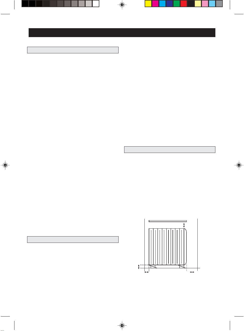
1, pero pueden servir cualquier otro objeto como libros, papeles, cajitas de cartón etc... (figura 2). En todo
caso deben respetarse unas mínimas distancias como
se indica en el dibujo.
Eventual repisa
Pared u
objeto más
próximo
a la
izquierda
Mínimo 150 mm
Pared u
objeto mas
próximo
a la
derecha
Esta es una decisión muy importante y que debe ser
realizada con método y criterio, aparato por aparato.
Sería una pena arruinar el acierto de elegir la
de Calefacción UFESAde Calefacción UFESA
de Calefacción UFESA con un emplazamiento desacer-
de Calefacción UFESAde Calefacción UFESA
tado o una mala fijación.
Vamos a empezar por el emplazamiento. Debemos elegir una pared en la que se pueda disponer de un espacio sin muebles para situar el aparato. También deberemos evitar objetos en su entorno próximo como muebles, cortinas u otros aparatos.
L.I. ET9704… 11/3/05, 16:543
InstalaciónInstalación
Instalación
InstalaciónInstalación
Mínimo
150 mm
Mínimo 100mm
Mínimo 250 mm
(lateral de mandos)
Una vez posicionado el emisor termoeléctrico deberemos señalar su situación. Para ello nos serviremos de la
3

plantilla de posicionamiento que se acompaña con cada
aparato y que deberemos pegar a la pared, tal y como
se indica en la figura. Ahora podemos retirar el aparato.
6. Meter los tacos y roscar los tornillos, sin apretarlos
totalmente.
7. Nivelar la percha y apretar firmemente los tornillos.
Retirar la pieza metálicaRetirar la pieza metálica
8.
Retirar la pieza metálica que ha mantenido la distan-
Retirar la pieza metálicaRetirar la pieza metálica
cia y la posición correcta de los dos soportes de plástico. Se recomienda guardar la pieza metálica para una
reubicación o rectificación posterior.
2. Con la ayuda de una regla, o de un simple cartón de
borde liso y uniforme, marcaremos la prolongación de
las tres líneas impresas en la plantilla. Así tendremos dos
++
+ marcadas que se corresponden con el centro de los
++
agujeros de Ø 6 mm x 30 mm que procederemos a
perforar.
Podemos despegar la plantilla que gracias a su controlada fuerza de adhesión se podrá retirar sin dejar ninguna marca o señal, siempre y cuando la pintura tenga una
resistencia normal. (Si hubiera alguna duda al respecto
deberá probarse previamente en una zona de pared
que quede habitualmente oculta).
3. Meter los tacos Ø 6 mm incluidos en el kit de fijación, presentar la percha y roscar los tornillos también
incluidos, hasta que la percha quede tensa.
Los tornillos deben quedar ahora en el centro de losLos tornillos deben quedar ahora en el centro de los
Los tornillos deben quedar ahora en el centro de los
Los tornillos deben quedar ahora en el centro de losLos tornillos deben quedar ahora en el centro de los
agujeros rasgadosagujeros rasgados
agujeros rasgados para que pueda permitir posterior-
agujeros rasgadosagujeros rasgados
mente una pequeña rectificación, si fuera necesaria, tanto hacia la derecha como hacia la izquierda.
4. Alinear la percha por la derecha bien con la ayuda
de un nivel o bien controlando que la distancia desde
el suelo, si éste es uniforme y plano, es la misma tanto
en la parte derecha como en la izquierda. Ver fig. 4
5. Señalar los agujeros rasgados y retirar la percha hasta
que la posición de los agujeros quede libre. Marcar el
centro de estos agujeros y perforar con broca Ø 6 mm.
A
B
A = B
9. Colgar el aparato y empujarlo por abajo hacia la pared hasta que oigamos el
que el aparato ha quedado perfectamente fijado.
Este kit de sujeción a la pared compuesto por percha,
tornillos, tacos y plantilla se entrega dentro del embalaje de cada aparato.
10. En lugares donde no sea posible fijar el emisor a la
pared, por ejemplo, en espacios acristalados, con paneles separadores o muros poco consistentes, será necesario fijar el emisor al suelo mediante el kit opcional
suelo, referencia 493039, que el usuario podrá encontrar en los Servicios Técnicos Autorizados.
4. CONEXIÓN ELÉCTRICA4. CONEXIÓN ELÉCTRICA
4. CONEXIÓN ELÉCTRICA
4. CONEXIÓN ELÉCTRICA4. CONEXIÓN ELÉCTRICA
Para que los aparatos UFESA funcionen satisfactoriamente y sin presentar ningún problema, es necesario realizar una correcta conexión eléctrica. Ésta es sumamente
sencilla pero hay que respetar ciertas condiciones. En
primer lugar deberemos disponer de una instalación
eléctrica, que se corresponda con el voltaje indicado
en el aparato, que cumpla con toda la
gentegente
gente y tener contratada la
gentegente
nectar todos los aparatos.
Los aparatos
ser conectados de forma permanente a una instalación fija.
El circuito de alimentación del emisor debe contar con
un interruptor de corte omnipolar con una separación
de contactos de al menos 3 m/m.
Varios aparatos pueden estar protegidos por un
magnetotérmico (diferencial) común, pero respetando
siempre que la suma de las intensidades de los aparatos, cualesquiera que sean, conectados simultáneamente a cada protector magnetotérmico (diferencial), no
pueda superar la capacidad de éste. A estos efectos y
a los de sección de cable necesario se indica a continuación la intensidad que se corresponde con la potencia y tensión nominales.:
Digital Timer y DomoticDigital Timer y Domotic
Digital Timer y Domotic están destinados a
Digital Timer y DomoticDigital Timer y Domotic
500 W: 2,2 A 500 W: 2,2 A
500 W: 2,2 A
500 W: 2,2 A 500 W: 2,2 A
750 W: 3,3 A 750 W: 3,3 A
750 W: 3,3 A
750 W: 3,3 A 750 W: 3,3 A
«clic»«clic»
«clic» de blocaje. Comprobar
«clic»«clic»
legislación vi-legislación vi-
legislación vi-
potencia necesariapotencia necesaria
potencia necesaria para co-
potencia necesariapotencia necesaria
1000 W: 4,3 A1000 W: 4,3 A
1000 W: 4,3 A
1000 W: 4,3 A1000 W: 4,3 A
1500 W: 6,5 A1500 W: 6,5 A
1500 W: 6,5 A
1500 W: 6,5 A1500 W: 6,5 A
legislación vi-legislación vi-
4
L.I. ET9704… 11/3/05, 16:544

Para mayor claridad ver el ejemplo en la figura.
15 A 10 A
Marrón (fase)
Azul
(Neutro)
500W=2,2A
Marrón
(fase)
750W=3,3A
1000W=4,3A
1000W=4,3A
1500W=6,5A
1000W=4,3A
Después deberemos asignar un punto de conexión cerca de la ubicación del aparato. Los modelos Domótico
y Digital se suministra con un cable manguera de conexión. Si el punto de conexión más próximo estuviera
más alejado de lo que permite la manguera, sería necesario sustituir la manguera por otra más larga o establecer una nueva toma de corriente próxima al aparato.
Esta nueva toma de corriente deberá ser igualmente conforme a la legislación vigente.
gro, por un servicio autorizado por el fabricante. (Ver
hoja adjunta).
Todos los cables internos, conductores, tierra y cable
Domótico son de 1 mm. de sección. La manguera de
alimentación es diferente según el tipo de aparato de
que se trate. Las diferentes combinaciones son éstas:
-ELECTRONIC-ELECTRONIC
-ELECTRONIC
-ELECTRONIC-ELECTRONIC
MODELOS:
ET9704 ET9708
ET9706 ET9712
Estos modelos se suministran con clavija estandar modelo Schuco con conexión a tierra, ya que estos modelos no tienen posibilidad de conexión domótica.
-DIGITAL TIMER-DIGITAL TIMER
-DIGITAL TIMER
-DIGITAL TIMER-DIGITAL TIMER
MODELOS:
ET9804 ET9808
ET9806 ET9812
Dado que se trata de una aparato fijo, recomendamos
conectarlo a la red por medio de una conexión fija y no
enchufable. Por esta razón si en el punto elegido hubiera
una base de enchufe, sería necesario sustituirla por una
salida de cable con regleta de 3 vías y por la tapa correspondiente. Si debemos hacer una nueva caja de conexión, recomendamos que el centro de ésta se sitúe
aproximadamente a unos 100 mm a la derecha del aparato y a unos 100 mm por encima de la parte baja del
aparato. Nunca debe situarse ni detrás ni encima del
emisor termoeléctrico.
Una vez colocado el aparato y dispuesta la base de
conexión deberemos cortar la manguera a la medida
necesaria (domótico y digital), desforrarla y pelar las
puntas de los cables internos. Si la distancia entre aparato y punto de conexión es corta, puede dejarse la
manguera al aire. Si por el contrario hay bastante manguera suelta recomendamos utilizar canaletas para proteger y ocultar la manguera en su interior. Ver figura.
Si la manguera de conexión de esta unidad sufriera algún daño, deberá ser sustituida, a fin de evitar un peli-
-DOMOTIC PROGRAM-DOMOTIC PROGRAM
-DOMOTIC PROGRAM
-DOMOTIC PROGRAM-DOMOTIC PROGRAM
MODELOS:
ET9904 ET9908
ET9906 ET9912
-DOMOTIC REMOTE-DOMOTIC REMOTE
-DOMOTIC REMOTE
-DOMOTIC REMOTE-DOMOTIC REMOTE
MODELOS:
ET9900
Manguera de cuatro cables: Marrón (fase), Azul (neutro), Amarillo-verde (tierra) y Negro (cable domótico)
Se deben conectar los tres primeros en sus correspondientes conexiones. Para el cable domótico (negro) ver
conexión domótica.
5. CONEXIÓN DOMÓTICA5. CONEXIÓN DOMÓTICA
5. CONEXIÓN DOMÓTICA
5. CONEXIÓN DOMÓTICA5. CONEXIÓN DOMÓTICA
Todos los aparatos digital y domótico disponen además del cable de fase y de neutro, y, su correspondiente de tierra, cuando es necesario, de un cable adicional color negro (cable piloto de domótica).
Los aparatos
recibirrecibir
recibir una señal domótica sistema Gifam.
recibirrecibir
Por otro lado, los aparatos
para
Digital y DomoticDigital y Domotic
Digital y Domotic están preparados para
Digital y DomoticDigital y Domotic
DomoticDomotic
Domotic están preparados
recibirrecibir
recibir y también para
recibirrecibir
DomoticDomotic
emitiremitir
emitir una señal domótica
emitiremitir
sistema Gifam. Esta señal de salida permite programar
los tiempos de parada, de marcha, en funcionamiento
de día, de noche y la posición antihielo del propio aparato y de sus subordinados.
Para que un aparato domótico controle al resto de aparatos domóticos o digitales, sólo es necesario conectar
entre sí todos los cables negros de los aparatos que
van a formar la instalación. El orden de conexión es
L.I. ET9704… 11/3/05, 16:545
5
irrelevante y lo mismo pueden ir todos a un punto que
pasar un cable en serie de uno a otro o mezclar ambas
formas.
La única condición es que estén todos los cables negros conectados entre sí y que este cable no se conecte a ningún otro ni de corriente ni de tierra. Ver figuras
A, B y C.
Por este cable va a pasar tensión de diferente voltaje
(máx. 230 V~) pero con muy baja intensidad. Recomendamos utilizar cable negro aislado y de la misma sección que el resto de la instalación. La conexión entre
cables deber hacerse con regletas de una vía del tipo
que corresponda a la sección del cable.
Si uno, varios o todos los aparatos no queremos
interrelacionarlos, el cable negro de ese o esos aparatos deberá quedar sin conectar y con la
temente aislada.temente aislada.
temente aislada.
temente aislada.temente aislada.
ATENCIÓNATENCIÓN
ATENCIÓN
ATENCIÓNATENCIÓN
punta suficien-punta suficien-
punta suficien-
punta suficien-punta suficien-
Si Ud desea realizar la instalación eléctrica de su hogar
debe tener en cuenta que los cables de conexión de
todos estos aparatos digitales o domóticos deberán conectarse a la red eléctrica en la misma fase y en su orden,
no respetar esta condición puede provocar un desajuste
en las ordenes emitidas por el aparato director:
6. DESCRIPCIÓN, NOMBRES Y FUNCIONES DE LOS MANDOS6. DESCRIPCIÓN, NOMBRES Y FUNCIONES DE LOS MANDOS
6. DESCRIPCIÓN, NOMBRES Y FUNCIONES DE LOS MANDOS
6. DESCRIPCIÓN, NOMBRES Y FUNCIONES DE LOS MANDOS6. DESCRIPCIÓN, NOMBRES Y FUNCIONES DE LOS MANDOS
6.1. ELECTRONIC6.1. ELECTRONIC
6.1. ELECTRONIC
6.1. ELECTRONIC6.1. ELECTRONIC
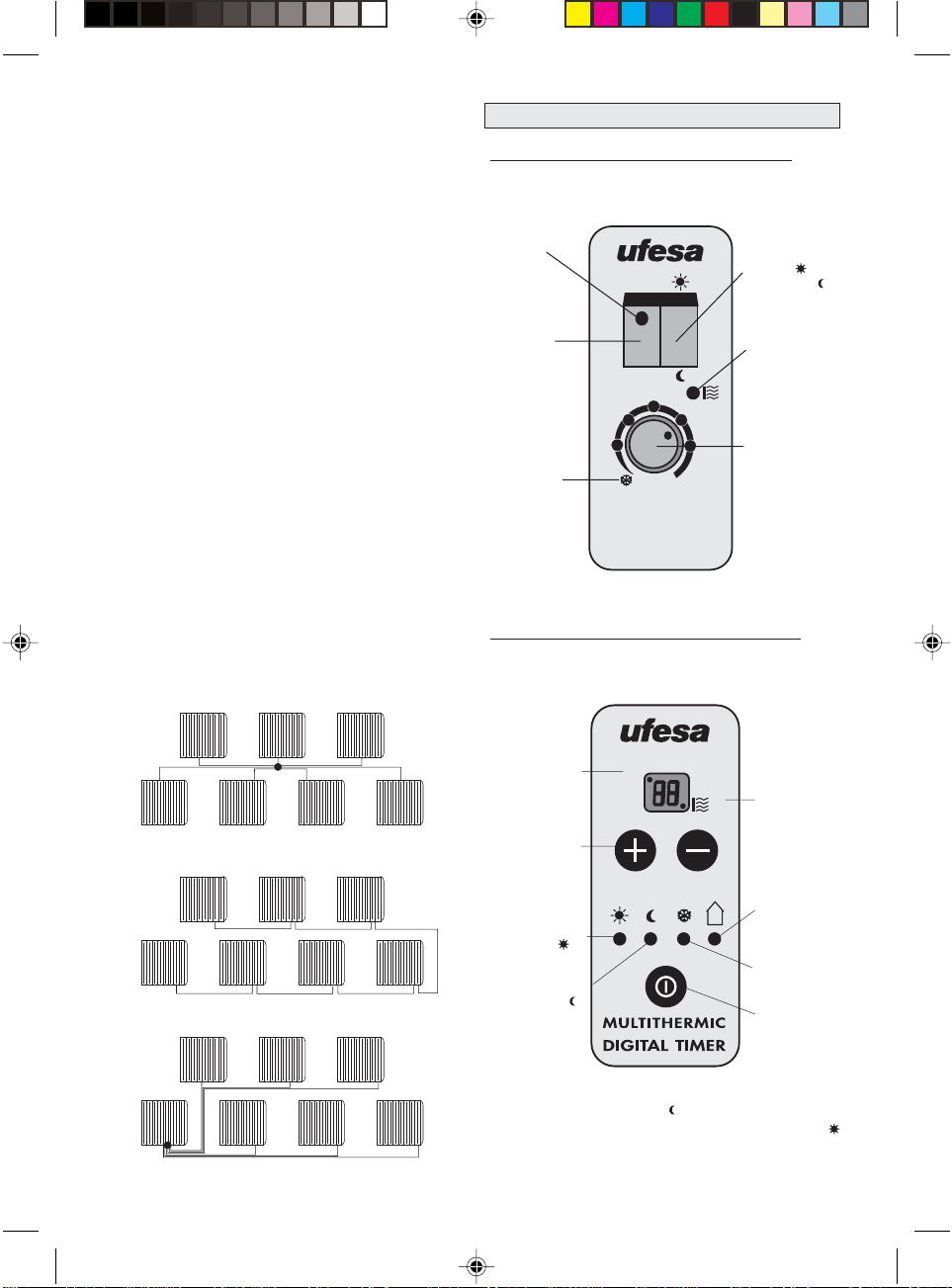
Posibilidades de conexión:Posibilidades de conexión:
Posibilidades de conexión: (Modo independiente)
Posibilidades de conexión:Posibilidades de conexión:
Piloto
luminoso
ON-OFF
Interruptor
basculante
ON-OFF
Posición
antihielo.
Hacer
coincidir
la referencia
del mando
con esta
señal
(ET9704-ET9706-ET9708-ET9712)
Posición
ON
3
2
1
max
MULTITHERMIC
ELECTRONIC
4
5
Confort
o Economía
Piloto luminoso
de función.
(aparato
conectado)
Termostato
electrónico
de 5 ºC a 35 ºC.
Aumenta la
temperatura
girando
en el sentido
de las agujas
del reloj.
MarrónMarrón
Marrón: Fase
MarrónMarrón
Azul:Azul:
Azul: Neutro
Azul:Azul:
Amarillo/Verde:Amarillo/Verde:
Amarillo/Verde: Tierra
Amarillo/Verde:Amarillo/Verde:
NegroNegro
Negro: Conexión Domótica
NegroNegro
6
Figura A
Figura B
Figura C
6.2. DIGITAL TIMER6.2. DIGITAL TIMER
6.2. DIGITAL TIMER (ET9804-ET9806-ET9808-ET9812)
6.2. DIGITAL TIMER6.2. DIGITAL TIMER
Posibilidades de conexión:Posibilidades de conexión:
Posibilidades de conexión: (Modo independiente-
Posibilidades de conexión:Posibilidades de conexión:
Domótico Subordinado)
OFF
(Aparato
desconectado)
Teclas para
selección de
temperaturas,
y timer
Piloto de función
CONFORT
Piloto de función
ECONOMIA
* La temperatura de consigna en (Economía) baja 3,5ºC aproximadamente en relación con la consignada en la posición
(Confort) sin modificar la posición del termostato.
OFF
@
Termostato ON
(Calentando
aparato)
Piloto
DOMOTICO
(Conectado)
Piloto posición
ANTIHIELO
Interruptor
ON-OFF
y selector
de funciones
L.I. ET9704… 11/3/05, 16:546

6.3. DOMOTIC PROGRAM (ET9904 - ET9906 - ET9908 -6.3. DOMOTIC PROGRAM (ET9904 - ET9906 - ET9908 -
SS
SS
6.3. DOMOTIC PROGRAM (ET9904 - ET9906 - ET9908 -
6.3. DOMOTIC PROGRAM (ET9904 - ET9906 - ET9908 -6.3. DOMOTIC PROGRAM (ET9904 - ET9906 - ET9908 ET9912) Y DOMOTIC REMOTE (ET9900)ET9912) Y DOMOTIC REMOTE (ET9900)
ET9912) Y DOMOTIC REMOTE (ET9900)
ET9912) Y DOMOTIC REMOTE (ET9900)ET9912) Y DOMOTIC REMOTE (ET9900)
Posibilidades de conexión:Posibilidades de conexión:
Posibilidades de conexión: (Modo independiente
Posibilidades de conexión:Posibilidades de conexión:
Domótico Subordinado-Director)
PANTALLA DE CRISTAL LÍQUIDOPANTALLA DE CRISTAL LÍQUIDO
PANTALLA DE CRISTAL LÍQUIDO
PANTALLA DE CRISTAL LÍQUIDOPANTALLA DE CRISTAL LÍQUIDO
Interpretación de las indicaciones.
Esta pantalla solamente va equipada en los aparatos
Domotic
Una primera pulsación en cualquiera de las seis teclas
enciende la luz y activa el teclado. No ejecuta ninguna
otra orden. Transcurridos 5” sin operar se apaga la luz y
el teclado queda en reposo. En programación el tiempo es de 10”.
Pantalla
de cristal
líquido
Selección
modo de
funcionamiento:
-CONFORT
-ECONOMIC
-ANTIHIELO
-PROG
-OFF
Entrada
a la
función de
programación.
Disminuir temperatura.
Aumentar minutos.
Rechazar opciones.
Retroceder.
SEL
P
Bloqueo/
Desbloqueo
Limitador de
temperatura
máxima
Validación
de programas
y ordenes.
Configuración:
O.K.
-hora
-día de la semana
-posición jerárquica
-selección de
R
opciones
Aumentar temperatura.
Aumentar horas.
Aceptar opciones.
Avanzar
Modo
Subordinado
Modo
Director
Modo
Independiente
Posición
Confort
Posición
Economía
Termómetro
temperatura
real
Indicación de
programación
Día/programa
Cada vez que se pulsa una tecla la pantalla se ilumina y se
activa el teclado. Permanece así hasta 10 segundos después de
tocar la última tecla. En programación son 15 segundos.
Reloj 24H.
Siempre en
pantalla si el
aparato esta
conectado a la
red.Incluso en
OFF
Posición
antihielo
Temperatura
programada
Mandos
bloqueados
Aparato
calentando
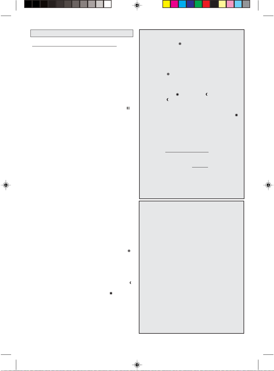
Los Emisores Térmicos UFESA, en sus diferentes variantes, incorporan las siguientes funciones:
REMOTOREMOTO
REMOTO
FUNCIONES DE PROGRAMACIONFUNCIONES DE PROGRAMACION
FUNCIONES DE PROGRAMACION
FUNCIONES DE PROGRAMACIONFUNCIONES DE PROGRAMACION
- Posición Antihielo:- Posición Antihielo:
- Posición Antihielo:
- Posición Antihielo:- Posición Antihielo:
- Posición Confort/ Economía:- Posición Confort/ Economía:
- Posición Confort/ Economía:
- Posición Confort/ Economía:- Posición Confort/ Economía:
- Posición Domótica:- Posición Domótica:
- Posición Domótica:
- Posición Domótica:- Posición Domótica:
- Posición independiente- Posición independiente
- Posición independiente
- Posición independiente- Posición independiente
- Posición Subordinada:- Posición Subordinada:
- Posición Subordinada:
- Posición Subordinada:- Posición Subordinada:
- Posición Director:- Posición Director:
- Posición Director:
- Posición Director:- Posición Director:
- Función timer:- Función timer:
- Función timer:
- Función timer:- Función timer:
- Programación semanal:- Programación semanal:
- Programación semanal:
- Programación semanal:- Programación semanal:
- Control electrónico- Control electrónico
- Control electrónico
- Control electrónico- Control electrónico
- Control vía telefónica- Control vía telefónica
- Control vía telefónica
- Control vía telefónica- Control vía telefónica
ELECTRONICOSELECTRONICOS
ELECTRONICOS
ELECTRONICOSELECTRONICOS
ET9704-ET9706-ET9708-ET9712ET9704-ET9706-ET9708-ET9712
ET9704-ET9706-ET9708-ET9712
ET9704-ET9706-ET9708-ET9712ET9704-ET9706-ET9708-ET9712
XX
X
XX
XX
X
XX
XX
X
XX
XX
X
XX
DIGITALESDIGITALES
DIGITALES
DIGITALESDIGITALES
ET9804-ET9806-ET9808-ET9812ET9804-ET9806-ET9808-ET9812
ET9804-ET9806-ET9808-ET9812
ET9804-ET9806-ET9808-ET9812ET9804-ET9806-ET9808-ET9812
XX
X
XX
XX
X
XX
XX
X
XX
XX
X
XX
XX
X
XX
XX
X
XX
DOMOTICOSDOMOTICOS
DOMOTICOS
DOMOTICOSDOMOTICOS
ET9904-ET9906-ET9908-ET9912ET9904-ET9906-ET9908-ET9912
ET9904-ET9906-ET9908-ET9912
ET9904-ET9906-ET9908-ET9912ET9904-ET9906-ET9908-ET9912
XX
X
XX
XX
X
XX
XX
X
XX
XX
X
XX
XX
X
XX
XX
X
XX
XX
X
XX
REMOTOREMOTO
ET9900ET9900
ET9900
ET9900ET9900
XX
X
XX
XX
X
XX
XX
X
XX
XX
X
XX
XX
X
XX
XX
X
XX
XX
X
XX
XX
X
XX
7
L.I. ET9704… 11/3/05, 16:547
7. PUESTA EN MARCHA7. PUESTA EN MARCHA
7. PUESTA EN MARCHA
7. PUESTA EN MARCHA7. PUESTA EN MARCHA
DEFINICION DE TERMINOSDEFINICION DE TERMINOS
DEFINICION DE TERMINOS
DEFINICION DE TERMINOSDEFINICION DE TERMINOS
7.1 ELECTRONIC7.1 ELECTRONIC
7.1 ELECTRONIC
7.1 ELECTRONIC7.1 ELECTRONIC
7.1.1. Definición7.1.1. Definición
7.1.1. Definición
7.1.1. Definición7.1.1. Definición
(ET9704-ET9706-ET9708-ET9712)
El termostato electrónico del control Electrónico básico con que se equipan los Emisores Termoeléctricos
UFESA de este nivel, están gobernados por un circuito
integrado específico con sensibilidad de 0,1 ºC. La sonda de temperatura está ubicada en la corriente de aire
que entra directamente del exterior.
La selección de temperatura se realiza girando el mando correspondiente. Gracias a un piloto luminoso que
se enciende cuando el aparato está calentando ( )
podemos precisar la temperatura adecuada haciéndola coincidir con la posición de equilibrio de apagado/
encendido.
Estos modelos cuentan además con un selector de
modos Confort / Economía
7.1.2. Operativa7.1.2. Operativa
7.1.2. Operativa
7.1.2. Operativa7.1.2. Operativa
2.1. Selección de funcionamiento2.1. Selección de funcionamiento
2.1. Selección de funcionamiento
2.1. Selección de funcionamiento2.1. Selección de funcionamiento
Accionando el interruptor basculante pasaremos de ON
a OFF y a la inversa. El piloto luminoso encendido nos
indicará la posición ON.
2.2. Selección de temperatura2.2. Selección de temperatura
2.2. Selección de temperatura
2.2. Selección de temperatura2.2. Selección de temperatura
Girando el mando en el sentido de las agujas del reloj
aumentamos la temperatura y a la inversa. Para seleccionar la temperatura adecuada girar el mando hasta la posición de máxima temperatura. Una vez alcanzada la
temperatura ideal, con la ayuda de un termómetro o
por percepción sensorial disminuiremos girando lentamente el mando hasta que se apague el piloto correspondiente. Después podremos ajustarlo con ligeras correcciones.
2.3. Función Antihielo2.3. Función Antihielo
2.3. Función Antihielo
2.3. Función Antihielo2.3. Función Antihielo
Estando el aparato en ON, giramos el mando en el sentido contrario a las agujas del reloj hasta la posición ( ).
El aparato comenzará a funcionar automáticamente
cuando la temperatura ambiente llegue a 5ºC.
2.4. Selección modos Confort/Economía2.4. Selección modos Confort/Economía
2.4. Selección modos Confort/Economía
2.4. Selección modos Confort/Economía2.4. Selección modos Confort/Economía
Accionando la tecla correspondiente se pasa de uno a
otro modo de funcionamiento. El modo Economía ( )
baja la temperatura consignada 3,5ºC aproximadamente en relación consignada como Confort ( ) sin modificar la posición del termostato.
-Posición Antihielo (-Posición Antihielo (
-Posición Antihielo (
-Posición Antihielo (-Posición Antihielo (
))
):
))
Cuando nos ausentamos de casa por vacaciones, por
fin de semana, o por cualquier otra causa, una bajada
brusca de las temperaturas puede hacer que se congelen tuberias, plantas, etc.
La definición (
) permite con muy poco consumo mantener en estos casos la temperatura entre +5ºC y +7ºC
aproximadamente.
-Posición Confort (-Posición Confort (
-Posición Confort (
-Posición Confort (-Posición Confort (
) / Economía () / Economía (
) / Economía (
) / Economía () / Economía (
))
):
))
La selección ( ) hace disminuir la temperatura de consigna en 3,5 ºC. Así en las horas nocturnas podemos
elegir esta opción pudiendo recuperar posteriormente
la misma temperatura de consigna seleccionando (
También útil para los períodos en que nos ausentemos
de casa, manteniendo la temperatura en niveles de poco
consumo.
-Posición Domótica: (Sólo modelos
DomoticDomotic
Domotic)
DomoticDomotic
Los aparatos
para
Por otro lado, los aparatos
para
Digital Timer y DomoticDigital Timer y Domotic
Digital Timer y Domotic están preparados
Digital Timer y DomoticDigital Timer y Domotic
recibirrecibir
recibir una señal domótica sistema Gifam.
recibirrecibir
DomoticDomotic
Domotic están preparados
recibirrecibir
recibir y también para
recibirrecibir
DomoticDomotic
emitiremitir
emitir una señal domótica
emitiremitir
Digital Timer yDigital Timer y
Digital Timer y
Digital Timer yDigital Timer y
sistema Gifam. Esta señal de salida permite programar
los tiempos de parada, de marcha, en funcionamiento
de Confort, de Economía y la posición antihielo del propio aparato y de sus subordinados.
MODOS DE CONEXION-POSICION JERARQUICA:MODOS DE CONEXION-POSICION JERARQUICA:
MODOS DE CONEXION-POSICION JERARQUICA:
MODOS DE CONEXION-POSICION JERARQUICA:MODOS DE CONEXION-POSICION JERARQUICA:
-Posición independiente:-Posición independiente:
-Posición independiente:
-Posición independiente:-Posición independiente:
El aparato se encuentra en modo de función independiente, sin estar subordinado a ninguna orden o función de ningun emisor domótico en
modo Director.
-Posición Subordinada:-Posición Subordinada:
-Posición Subordinada:
-Posición Subordinada:-Posición Subordinada:
El aparato se encuentra subordinado a una orden
o función de un emisor domótico en modo Director.
-Posición Director:-Posición Director:
-Posición Director:
-Posición Director:-Posición Director:
El aparato se encuentra realizando las funciones
de gobernabilidad del resto de los aparatos conectados a el, bien sean en sus variantes, Digital o
Domótica.
NOTA:NOTA:
NOTA:
NOTA:NOTA:
Sólo un emisor térmico en su variante Domótico puede
ejercer como director de la instalación.
Los restantes aparatos domóticos deben de estar en posición subordinada. Si por error hubiera más de un
domótico ejerciendo funciones de director, los aparatos subordinados podrian recibir señales contradictorias que afectarian a su gobernabilidad.
) .
8
L.I. ET9704… 11/3/05, 16:558

7.2. DIGITAL TIMER 7.2. DIGITAL TIMER
7.2. DIGITAL TIMER
7.2. DIGITAL TIMER 7.2. DIGITAL TIMER
7.2.1. Definición7.2.1. Definición
7.2.1. Definición
7.2.1. Definición7.2.1. Definición
(ET9804-ET9806-ET9808-ET9812)
El termostato electrónico del equipamiento de control
Electrónico Digital con que cuentan los Emisores
Termoeléctricos UFESA, está gobernado por un
microprocesador dentro de una sensibilidad de 0.1ºC.
La sonda de temperatura está situada en el exterior del
aparato y su configuración compensada permite contrarrestar la influencia del calor interior.
La temperatura se ofrece en un display de dos dígitos
más una señal de aparato calentando (
) cuando el ter-
mostato está en posición cerrada.
La selección de temperatura se realiza mediante dos
pulsadores, (+ y -), mientras se visualiza la temperatura
en el display luminoso.
Cuenta con una posición de Off señalada por el punto
superior izquierdo del display, más tres posiciones de
selección manual de status de temperatura con señalizaciones ámbar en cada una de ellas y, finalmente, una
posición Domo, señalada con un led azul, en la que el
aparato atiende las señales domóticas externas provenientes de un aparato director (modo de función subordinada).
La selección se realiza pulsando la tecla (
) que hace
avanzar una posición rotativamente. Una pulsación mayor de 2” lleva el aparato a Off.
El control electrónico dispone de una memoria para los
casos en que se de un corte de la corriente eléctrica,
que mantiene la temperatura seleccionada y la selección de funcionamiento, sin límite de tiempo, hasta que
se reponga la energía.
Las funciones de programación TIMER y de limitación
de temperatura hacen que sea esta familia muy completa y, a la vez, de simple manejo.
7.2.2. Operativa7.2.2. Operativa
7.2.2. Operativa
7.2.2. Operativa7.2.2. Operativa
2.1. Selección de funcionamiento2.1. Selección de funcionamiento
2.1. Selección de funcionamiento
2.1. Selección de funcionamiento2.1. Selección de funcionamiento
Pulsando la tecla (
) avanza por cada pulsación, en forma rotativa, a: Off, Confort, Economía, Antihielo, Domo,
Off ... La selección queda definida por el único piloto
que está encendido de los que hay junto a cada señal.
Pasados 5’’sin operar vuelve a marcar la temperatura
ambiente y pasados otros 5’’ la luz queda más tenue en
reposo.
2.3. Limitación de temperatura máxima2.3. Limitación de temperatura máxima
2.3. Limitación de temperatura máxima
2.3. Limitación de temperatura máxima2.3. Limitación de temperatura máxima
Aunque el termostato tiene un campo de regulación
entre +5ºC y +35ºC, se puede limitar este campo reduciendo la temperatura máxima a voluntad hasta +15ºC,
es decir, se puede reducir el campo hasta dejarlo entre
+5ºC y +15ºC. Esta selección tiene un nivel de acceso
restringido puesto que es necesario conocer el procedimiento. Así se pueden evitar despilfarros o que, por
ejemplo, se asfixien las plantas que tanto hemos cuidado. Proceder de la siguiente manera:
1ºMantener pulsado [-] durante 5’’. Aparecerá parpadeando en la pantalla la limitación de la temperatura
máxima seleccionada (35ºC por defecto).
2º Pulsar [+] y [-] para ajustar la limitación que se desee
fijar. A cada pulsación se corresponde el incremento o
el decremento respectivo de 1ºC.
Transcurridos 5’’ sin pulsar estas teclas, se acepta el valor mostrándolo sin parpadear y pasados otros cinco
segundos se muestra la temperatura ambiente.
2.4. Función Timer2.4. Función Timer
2.4. Función Timer
2.4. Función Timer2.4. Función Timer
Esta función permite programar bien una parada, o bien
un arranque del aparato en una selección entre 1 hora y
99 horas. Esta ambivalencia de función permite mantener el aparato calentando durante un tiempo determinado cuando nos vamos a la cama o bien, que se encienda antes de levantarnos o antes de que regresemos
tras un fin de semana.
Para activar esta función:
- Mantener pulsado [+] durante 5 segundos. Aparece
en pantalla [00] parpadeando, salvo que ya estuviera
activada la función Timer, en cuyo caso marcará el tiempo que falta.
- Pulsando [+] y [-] se selecciona el tiempo que se desea
fijar. Transcurridos 5 segundos sin pulsar queda aceptada la programación. La pantalla vuelve a marcar la temperatura ambiente y el reloj comienza su cuenta a trás.
- Una vez consumido el tiempo programado, el aparato hará una de estas dos cosas:
- Si está en OFF se pondrá en Confort.
- Si está en Confort, Economía, Antihielo o Domo, se
parará (OFF).
2.2. Selección de temperatura2.2. Selección de temperatura
2.2. Selección de temperatura
2.2. Selección de temperatura2.2. Selección de temperatura
Pulsando [+] o [-] la luz del display se incrementa, mostrando la temperatura ambiente durante 1” pasando a
señalar seguidamente la temperatura seleccionada. A
cada pulsación en [+] y en [-] se aumenta y disminuye
1ºC respectivamente.
L.I. ET9704… 11/3/05, 16:559
7.2.3. Configuración inicial7.2.3. Configuración inicial
7.2.3. Configuración inicial
7.2.3. Configuración inicial7.2.3. Configuración inicial
De la cadena de montaje todos los aparatos salen con
la siguiente configuración:
3.1. Selección de funcionamiento: OFF
3.2. Temperatura de consigna: 20ºC
3.3. Límite de temperatura máxima: 35ºC
9

7.3. DOMOTIC PROGRAM7.3. DOMOTIC PROGRAM
7.3. DOMOTIC PROGRAM
7.3. DOMOTIC PROGRAM7.3. DOMOTIC PROGRAM
(ET9900-ET9904-ET9906-
ET9908-ET9912)
7.3.1. Definición7.3.1. Definición
7.3.1. Definición
7.3.1. Definición7.3.1. Definición
El termostato electrónico del equipamiento de control
de los Emisores Termoeléctricos UFESA, en su versión
Digital Domótico, está gobernado por un
microprocesador con una sensibilidad de 0,1ºC.
La sonda de temperatura está situada en el exterior del
aparato y su configuración compensada permite contrarrestar el calor interior.
Este microprocesador de gran potencia, es capaz de
gobernar todas y cada uno de las múltiples funciones
con que cuenta el aparato y que son las que a continuación se describen:
A. Posición jerárquica:A. Posición jerárquica:
A. Posición jerárquica: Permite configurar el aparato
A. Posición jerárquica:A. Posición jerárquica:
en posición de Director, Subordinado, o bien Independiente.
B. Selección de funcionamiento:B. Selección de funcionamiento:
B. Selección de funcionamiento: Permite seleccionar
B. Selección de funcionamiento:B. Selección de funcionamiento:
o desactivar cada una de las opciones de Confort (
Economía ( ) , Antihielo ( ) , Off y Prog.
C. Programación permanente:C. Programación permanente:
C. Programación permanente: Pueden introducirse cua-
C. Programación permanente:C. Programación permanente:
tro diferentes programas de 24 horas que pueden
repartirse hasta en 15 períodos diferentes de tiempo,
asignando a cada uno de ellos la posición de Confort
( ), Economía ( ) u Off. A cada día de la semana podemos asignar el programa que queramos. Así podríamos tener un programa para funcionamiento de Lunes a
Viernes, otro para los Sábados y otro para los Domingos y nos podría quedar otro programa en reserva y
sustituirlo por uno de los anteriores cuando se quiera.
D. Funcionamiento directoD. Funcionamiento directo
D. Funcionamiento directo (sin programa). Tanto en Di-
D. Funcionamiento directoD. Funcionamiento directo
rector como en Independiente. Pulse cualquier tecla
para activar el Led. Seguidamente pulse SEL repetidamente hasta que aparezca la función deseada Confort
( ) Economía ( ), Antihielo ( ), Off y Prog. La opción
aparecerá intermitentemente hasta que valide la función
con OK.
E. Funciones especiales:E. Funciones especiales:
E. Funciones especiales: De blocaje de mandos, de lí-
E. Funciones especiales:E. Funciones especiales:
mite en la selección de temperatura máxima, de funcionamiento silencioso y por último la función de luz y
pantalla permanentemente activadas.
F. Reserva de energía:F. Reserva de energía:
F. Reserva de energía: El control electrónico dispone
F. Reserva de energía:F. Reserva de energía:
de una reserva de energía sin pila, ni batería ni ningún
otro elemento sujeto a sustitución, por si se da un corte
de la corriente eléctrica, que mantiene, con la pantalla
apagada, todos los valores de programación y el reloj
en marcha. Esta energía dura como mínimo unas 6 ho-
ras. Una vez agotada la reserva deberá ponerse únicamente en hora y día ya que mantendrá todos los valores de selección y de programación.
Todas estas selecciones se visualizan en una pantalla
de cristal líquido, en la que además se ofrece de forma
permanente reloj en función de 24h, día de la semana,
temperatura ambiente, temperatura seleccionada, llave
y señal de calentando.
En la posición de Director el aparato envía las señales,
vía cable Domo, que gobiernan al resto de aparatos conectados al sistema, bien sean digitales o bien
domóticos. En subordinado atiende las órdenes que
recibe de otro domótico. En la posición de independiente el aparato funciona normalmente como un aparato aislado sin influir ni dejarse influir por señales
domóticas.
7.3.2. Operativa7.3.2. Operativa
7.3.2. Operativa
7.3.2. Operativa7.3.2. Operativa
De fábrica el aparato se suministra con la opción de luz
y pantalla desactivados por defecto, pero si Ud lo desea, podrá programarlo para dejar la pantalla con la luz
siempre encendida y con el teclado permanentemente
activado.
) ,
En este caso ya no será necesario pulsar previamente
tecla alguna antes de iniciar cualquier procedimiento
para el encendido del LCD.
Para activar esta función deberá activarse el teclado (pulsar cualquier tecla para activar la pantalla) y seguidamente la secuencia O.K. [+] SEL. Para desactivarla pulsar directamente O.K. [+] SEL.
En funcionamiento normal (sin activar esta función) un
procedimiento de selección o programación se confirma apagándose la luz. Activada esta función (luz permanente) la confirmación viene dada por un biip algo
más prolongado.
Si Ud va a proceder a programar en modo normal (luz y
pantalla NO permanentemente activados) tenga en
cuenta que la primera pulsación realizada en cualquiera de las teclas tan sólo realizará la opción de encendido del LCD. (no actuará en ningún caso como una orden de programación).
A continuación se describe la operativa para todas las
funciones que es capaz de realizar el Control Domótico
de los Emisores Termoeléctricos:
A. Configuración del aparato.A. Configuración del aparato.
A. Configuración del aparato. Se realiza una sola vez
A. Configuración del aparato.A. Configuración del aparato.
al instalarlo y cuando se requiera una nueva configuración.
B. RelojB. Reloj
B. Reloj (24h.) Pulsar tecla R. El reloj parpadea. Con [+]
B. RelojB. Reloj
avanzan las horas y con [-] avanzan los minutos. Con
O.K. se confirma esa hora y parpadea el indicador del
día 1.
10
L.I. ET9704… 11/3/05, 16:5510

C. Día de la semana.C. Día de la semana.
C. Día de la semana. Con [+] y [-] se avanza o retrocede
C. Día de la semana.C. Día de la semana.
el indicador del día de la semana. Con O.K se confirma
y pasa a parpadear D. (director)
D. Estado jerárquico.D. Estado jerárquico.
D. Estado jerárquico. Con [+] y [-] se avanza o se retro-
D. Estado jerárquico.D. Estado jerárquico.
cede de D (director) a S (subordinado) o a I (independiente). Con O.K. se confirma el estado jerárquico que
está parpadeando. Si la configuración jerárquica ha sido
S termina la configuración y pasa a pantalla normal. En
otro caso, parpadea (
E. Selección de opciones.E. Selección de opciones.
E. Selección de opciones. Con [+] se activa y con [-]
E. Selección de opciones.E. Selección de opciones.
se desactiva (
activa y con [-] se desactiva. Pasa a (
).
). Pasa a ( ) que parpadea. Con [+] se
), a Off y a Prog
que se activan y se desactivan de igual manera. Pasa a
pantalla normal y queda fijada la configuración.
F. ProgramaciónF. Programación
F. Programación
F. ProgramaciónF. Programación
F.1. Configuración inicialF.1. Configuración inicial
F.1. Configuración inicial
F.1. Configuración inicialF.1. Configuración inicial
De la cadena de montaje todos los aparatos salen con
la siguiente configuración:
- Posición jerárquica: D (Director)- Posición jerárquica: D (Director)
- Posición jerárquica: D (Director)
- Posición jerárquica: D (Director)- Posición jerárquica: D (Director)
- Estado de selección: Off- Estado de selección: Off
- Estado de selección: Off
- Estado de selección: Off- Estado de selección: Off
- Temperatura de consigna: 20ºC- Temperatura de consigna: 20ºC
- Temperatura de consigna: 20ºC
- Temperatura de consigna: 20ºC- Temperatura de consigna: 20ºC
- Límite de temperatura máxima: 35ºC- Límite de temperatura máxima: 35ºC
- Límite de temperatura máxima: 35ºC
- Límite de temperatura máxima: 35ºC- Límite de temperatura máxima: 35ºC
Programa A: Lunes, Martes, Miércoles, Jueves y Viernes
6,30
0
Programa B: Sábados
8
0
Programa C: Domingos
8,30
0
Programa D: Sin asignar
6,30
12,30 18 24
8,30 14,30
12,30 19 24
9,30 17
10,30 16
21,30
22
18 24
21,30
18 24
Después de activar el teclado (pulsar cualquier tecla),
pulsar la tecla P Parpadean PROG y todos los
de la
línea A. Nuevas pulsaciones en P hacen que pasen a
parpadear los de B, de C ó de D.
Cada programa A, B, C, y D ofrecen la posibilidad de
seleccionar funciones diferentes en varios intervalos de
horas hasta completar el día 24:00
Una vez programado el último intervalo del Modo A
hasta 24:00, ofrece automáticamente la posibilidad de
modificar el programa de fábrica B , y así sucesivamente con el programa C y con D.
Dejémoslo en
AA
A. El reloj marca 00.00 y parpadea Eco
AA
( ). Pulsando [+] se avanza y pulsando [-] se retrocede
a Confort ( ), antihielo ( ) y OFF. Con O.K. se valida la
opción que parpadea y pasa a parpadear la hora de
finalización de éste primer tramo.
Con [+] se seleccionan las horas y con [-] los minutos,
siempre en sentido ascendente. Con O.K. se valida y
pasa al siguiente tramo de éste programa A que se realiza siguiendo los mismos pasos. Así todos los tramos
necesarios hasta que se llegue a 24:00 y se confirme
pulsando O.K. Pasa al programa B.
F.3. Programa BF.3. Programa B
F.3. Programa B
F.3. Programa BF.3. Programa B
Igual que el programa A . Una vez validado 24:00 pasa
al programa C.
F.4. Programa CF.4. Programa C
F.4. Programa C
F.4. Programa CF.4. Programa C
Igual que los programas A y B. Una vez validado 24:00
pasa al programa D.
F.5. Programa DF.5. Programa D
F.5. Programa D
F.5. Programa DF.5. Programa D
Igual que los programas A, B y C. Una vez validado 24:00
pasa a la asignación de programas.
F.6. Asignación de programasF.6. Asignación de programas
F.6. Asignación de programas
F.6. Asignación de programasF.6. Asignación de programas
El O.K. de 24:00 del programa D lleva a la asignación de
programas. En éste momento se muestran todos los
de los programas asignados. También se puede acceder mas directamente sin pasar por toda la programación pulsando repetidas veces la tecla P hasta que en la
cuadrícula de programación aparezcan los de los programas asignados.
0
8,30 16
21,30
Si Ud. desea modificar los programas memorizados de
fábrica actúe del modo siguiente:
F.2. Configuración del Programa AF.2. Configuración del Programa A
F.2. Configuración del Programa A
F.2. Configuración del Programa AF.2. Configuración del Programa A
Si el aparato está ejecutando un programa es
recomendable salir de la seleción PROG antes de
empezar a programar
L.I. ET9704… 11/3/05, 16:5511
Parpadea el si lo hubiera, del día 1 también el indicativo del 1 . Con [+] bajamos el con [-] lo subimos y
con O.K lo confirmamos. Pasa a parpadear el indicativo
del 2 y el si lo hubiera. Con [+] , [-] u O.K. se procede
hasta alcanzar el día 7 con cuyo O.K. pasa a pantalla
normal.
F.7. ObservacionesF.7. Observaciones
F.7. Observaciones
F.7. ObservacionesF.7. Observaciones
En cualquier punto de la programación una pulsación
sostenida (más de dos segundos) en O.K. validará la
información en pantalla dando por terminada la pro-
11

gramación y pasando a pantalla normal. De igual manera la validará y pasará a pantalla normal cuando no se
pulsa ninguna tecla durante 15”.
Puede haber días sin tener asignada ninguna programación (por defecto se situará en OFF) y programaciones
sin adjudicar a ningún día. En cambio, no es posible
más de un programa para cada día.
G. Selección de funcionamientoG. Selección de funcionamiento
G. Selección de funcionamiento
G. Selección de funcionamientoG. Selección de funcionamiento
Pulsando la tecla SEL aparece parpadeando la primera
opción habilitada en el procedimiento 7.3.2 E Nuevas
pulsaciones en SEL ofrecen rotativamente todas ellas.
Con O.K. o dejando pasar 10” se valida la que se encuentra parpadeando.
H. Selección de temperaturaH. Selección de temperatura
H. Selección de temperatura
H. Selección de temperaturaH. Selección de temperatura
Pulsando cualquier tecla se activa la función de tempe-ratura
y se ilumina la pantalla. Pulsaciones en [+] y en [-] harán aumentar y disminuir respectivamente 1ºC a cada pulsación.
Con O.K o dejando pasar 10” se valida la que aparece y pasa
a pantalla normal.
I. Funciones especialesI. Funciones especiales
I. Funciones especiales
I. Funciones especialesI. Funciones especiales
I.3. Modo silenciosoI.3. Modo silencioso
I.3. Modo silencioso
I.3. Modo silenciosoI.3. Modo silencioso
Cada vez que pulsamos una tecla podemos saber que
se ha pulsado correctamente gracias a que esta pulsación quedará confirmada con un “Bip”.
Modo silencioso: Se puede suprimir el sonido “Bip”
después de activar el teclado (pulsar cualquier tecla), y
pulsando seguidamente la secuencia O.K. [+] R. Para
activar nuevamente el sonido “Bip” repetir el mismo procedimiento: Activar teclado y O.K. [+] R.
I.4. Luz y pantalla permanentemente activadasI.4. Luz y pantalla permanentemente activadas
I.4. Luz y pantalla permanentemente activadas
I.4. Luz y pantalla permanentemente activadasI.4. Luz y pantalla permanentemente activadas
Si se quiere, puede dejarse la pantalla con la luz siem-pre
encendida y con el teclado permanentemente acti-vado. En
este caso ya no será necesario pulsar previa-mente tecla alguna antes de iniciar cualquier procedi-miento. Para activar
esta función deberá activarse el teclado (pulsar cualquier
tecla) y seguidamente la secuencia O.K. [+] SEL. Para
desactivarla pulsar directamente O.K. [+] SEL.
En funcionamiento normal (sin activar esta función) un
procedimiento de selección o programación se confirma apagándose la luz. Activada esta función (luz permanente) la confirmación viene dada por un biip algo
más prolongado.
I.1. Limitación de temperatura máximaI.1. Limitación de temperatura máxima
I.1. Limitación de temperatura máxima
I.1. Limitación de temperatura máximaI.1. Limitación de temperatura máxima
Aunque el termostato tiene un campo de regulación
entre +5ºC y +35ºC, se puede limitar este campo reduciendo la temperatura máxima a voluntad hasta +15ºC,
es decir se puede reducir el campo hasta dejarlo entre
+5ºC y +15ºC.
Esta selección tiene un nivel de acceso restringido puesto que es necesario conocer el procedimiento.
Así se pueden evitar despilfarros o que, por ejemplo,
se asfixien las plantas que tanto hemos cuidado. Proceder de la siguiente manera:
1º Activar el teclado (pulsar cualquier tecla).
2º Pulsar seguidamente O.K. [+] P. Aparecerá en pantalla la temperatura máxima seleccionable. Modificar con
[+] o [-] y validar con O.K. o dejando transcurrir 10”.
I.2. Blocaje de mandosI.2. Blocaje de mandos
I.2. Blocaje de mandos
I.2. Blocaje de mandosI.2. Blocaje de mandos
Con el aparato bloqueado ( ), cuando pulsemos una
tecla solamente se encenderá la pantalla que nos mostrará el signo de bloqueo. No permite ninguna otra maniobra que no sea la de desactivación.
Para activar y para desactivar esta función:
1º Activar el teclado (pulsar cualquier tecla).
2º Pulsar la secuencia O.K. [+] [-]
En la pantalla aparecerá el signo de la llave cuando esté
activado el blocaje.
I.5. Reloj y termómetroI.5. Reloj y termómetro
I.5. Reloj y termómetro
I.5. Reloj y termómetroI.5. Reloj y termómetro
En la pantalla podremos disponer simultánea y permanentemente de dos datos muy útiles, cuales son la hora
(24h.) y la temperatura (ºC). La única condición para
disponer de esta información es mantener el aparato
conectado a la red. No importa que esté en OFF o en
cualquier otra posición. El consumo eléctrico para esta
función es insignificante.
7.3.3 Control Remoto Telefónico (Modelo ET9900)7.3.3 Control Remoto Telefónico (Modelo ET9900)
7.3.3 Control Remoto Telefónico (Modelo ET9900)
7.3.3 Control Remoto Telefónico (Modelo ET9900)7.3.3 Control Remoto Telefónico (Modelo ET9900)
El modelo ET9900 es un modelo Domotic al que se le
ha incorporado el control remoto telefónico. Este control remoto nos permite, a través de un terminal telefónico, desde cualquier parte del mundo, gobernar los
modos de funcionamiento de un emisor Domotic
Remote que esté conectado a una línea telefónica y,
consecuentemente, si está actuando como Director,
controlar a través de él toda la instalación. Si está en la
posición Independiente sólo controlará al propio aparato. El control remoto no es operativo si el aparato está
en la posición Subordinado o desconectado de la red
eléctrica.
A. Conexión a la línea telefónicaA. Conexión a la línea telefónica
A. Conexión a la línea telefónica
A. Conexión a la línea telefónicaA. Conexión a la línea telefónica
En el punto de conexión del teléfono se debe intercalar un derivador con dos salidas. En una de ellas conectaremos el teléfono y en la otra, el cable telefónico con
conectores machos en sus extremos y con la suficiente
longitud para llegar hasta el emisor. En el lateral de mandos del aparato, en su parte inferior, hay un conector
hembra donde se deberá instalar el otro extremo del
cable telefónico.
12
L.I. ET9704… 11/3/05, 16:5512

B. UtilizaciónB. Utilización
B. Utilización
B. UtilizaciónB. Utilización
- Llamar al número de teléfono en que está conectado
el emisor Domotic Remote. Antes de hacerse cargo de
la llamada, el emisor esperará 7 tonos para permitir, si
alguien está en casa, que conteste normalmente a la llamada. Consumidos estos tonos, el aparato atiende la
llamada y activa el procedimiento identificándose:
CONTROL REMOTO
- Seguidamente, desde el teléfono llamante será preciso pulsar las teclas [1] y [2], una tras otra. En ausencia de
esta clave no se podrá avanzar. Una vez aceptada esta
contraseña recibiremos esta información:
ESTADO:
Indicará el que corresponda dentro de los
siguientes: A
PAGADO / CONFORT / ECONOMIC / PRO-
GRAMA
A continuación las posibles alternativas:
OPCIONES:
[2]
APAGADO
[5]
CONFORT
/ [3]
PROGRAMA
/ [4]
ECONOMIC
- Se deberá elegir la opción pulsando en el teléfono la
tecla correspondiente, que quedará confirmada con la
indicación verbal:
NUEVO ESTADO:
(El que sea, por ejemplo
APAGADO
activada se cancelaría y el contador de horas se situará
en [00].
Domotic.Domotic.
Domotic. El aparato quedará fuera de servicio hasta
Domotic.Domotic.
que se restablezca el suministro eléctrico.
Cuando la parada es por un corto espacio de tiempo,
por ejemplo con ocasión de una tormenta, el aparato
cuenta con un dispositivo QUE NO NECESITA PILA ni
ningún otro componente que deba sustituirse, que
mantiene el reloj en funcionamiento y toda la selección
y programación, aunque con la pantalla apagada durante algún tiempo.
Si la parada fuera prolongada el reloj y parte de la programación se pierden, sería necesario poner en hora y
reprogramar.
9. PROTECCIÓN DE SOBRECALENTAMIENTO9. PROTECCIÓN DE SOBRECALENTAMIENTO
9. PROTECCIÓN DE SOBRECALENTAMIENTO
9. PROTECCIÓN DE SOBRECALENTAMIENTO9. PROTECCIÓN DE SOBRECALENTAMIENTO
El aparato está concebido para que transmita el calor
por convección y por radiación. Esta función quedaría
/
dificultada si el aparato se cubre total o parcialmente
con ropas húmedas o secas, o con cualquier otro objeto. Además provocaría un sobrecalentamiento del
mismo. No obstante, el aparato cuenta con un dispositivo de seguridad que actúa desconectándolo, si se
produce un sobrecalentamiento. El aparato entra
automáticamente en funcionamiento una vez corregi-
)
da la anomalía.
Si no estamos conformes, se podrá elegir cuantas veces se quiera otra opción, que todos los caso será confirmada con la información de nuevo estado.
- Cuando estemos conformes deberemos confirmar
pulsado la tecla [1]. El aparato lo aceptará indicando:
A SU SERVICIO EL CONTROL REMOTO
- Colgar.
Nota importante: El control remoto no puede ser utilizado sobre una misma línea, de forma simultánea, con
otros aparatos de descuelgue automático como contestador, fax, o cualquier otro que se active antes que
el control remoto.
8. SI SE PRODUCE UN CORTE DE ELECTRICIDAD8. SI SE PRODUCE UN CORTE DE ELECTRICIDAD
8. SI SE PRODUCE UN CORTE DE ELECTRICIDAD
8. SI SE PRODUCE UN CORTE DE ELECTRICIDAD8. SI SE PRODUCE UN CORTE DE ELECTRICIDAD
Electronic.Electronic.
Electronic. El aparato se quedará fuera de servicio y
Electronic.Electronic.
volverá a conectarse una vez restablecida la corriente
eléctrica.
Digital.Digital.
Digital. El aparato quedará fuera de servicio y volverá a
Digital.Digital.
conectarse cuando se restablezca el suministro eléctrico. Todas las selecciones se mantienen sin sufrir ninguna modificación, salvo la función Timer, que si estuviera
Además de afectar negativamente al servicio de forma
ocasional, su repetición puede ser causa de una avería
que no quedaría cubierta por la garantía. Por todas estas
razones, se recomienda NO CUBRIR nunca el aparato.
10. MANTENIMIENTO PERIÓDICO10. MANTENIMIENTO PERIÓDICO
10. MANTENIMIENTO PERIÓDICO
10. MANTENIMIENTO PERIÓDICO10. MANTENIMIENTO PERIÓDICO
No es preciso realizar ningún tipo de mantenimiento
periódico de tipo técnico.
Sólo es necesaria una limpieza cada cierto tiempo, la
cual puede hacerse con aspirador, acoplándole un cepillo suave. También puede pasarse simplemente un
paño húmedo, o bien con un jabón neutro para quitar
manchas accidentales.
13
L.I. ET9704… 11/3/05, 16:5513

SS
SS
SS
SS
SSSSSSSSSS
SS
Luz y pantalla activadas
SEL O.K.
P
O.K.
R
SEL
O.K.
SEL
Significado del icono
Pulsar cualquier tecla
para activar el teclado.
SEL O.K.
P
R
Configuración
SEL O.K.
P
R
Selección
de
opciones
Programación
SEL O.K.
P
R
Prog. A
Hora
Avance
minutos
O.K.
Día
R
Avance
horas
SI NO SI NO SI NO SI NO SI NO
Sólo quedan seleccionados los modos pulsados
P
Avance
días
1=Lunes
2=Martes
3...
O.K.
Significado de los iconos
Avance modo
Avance horas
Avance minutos
O.K.
O.K.
Posición
jerárquica
D=Director
S=Subordinado
I= Independiente
O.K.
Avance
Fin
Confirmar y/o
avance
posición
00:00
06:30 08:30 12:30 14:30 18:00 21:30 24:00
O.K.
O.K.
O.K.
O.K.
O.K.
O.K.
Prog. B
Mismo proceso que A
O.K.
O.K.
O.K.
O.K.
O.K.
O.K.
O.K.
CD
Asignación de programas
O.K.
O.K.
O.K.
O.K.
14
L.I. ET9704… 11/3/05, 16:5514

SS
SS
SS
SS
Asignación de programas
SSSSSS
SS
SS
SS
Desde el programa D
Directo
SEL O.K.
P P P P P
P
R
Puesta en marcha
Selección de modo
Temperatura de consigna
Asignación
programas
O.K. O.K. O.K.
Ejemplo 2 preselecciones
SEL O.K.
P
SEL
SEL
SEL
O.K.
R
Ejemplo 3 preselecciones
P
R
SEL SEL SEL
O.K.
SEL
SEL O.K.
Límite de temperatura máxima
O.K.
Fin
+1ºC
SEL O.K.
P
R
O.K.
SEL O.K.
P
R
-1ºC
Modo Silencioso
SEL O.K.
Bip Bip
P
SEL O.K.
Bip Bip
P
R
O.K.
R
O.K.
R
R
O.K.
Blocaje de mandos
SEL O.K.
P
R
P
+1ºC
O.K.
-1ºC
O.K.
O.K.
15
L.I. ET9704… 11/3/05, 16:5515

ENGLISH
1. PRECAUTIONS1. PRECAUTIONS
1. PRECAUTIONS
1. PRECAUTIONS1. PRECAUTIONS
• The guarantee does not cover any damage that the
appliance may suffer as a result of disregarding the
instructions stated in this instruction manual.
• Check that the mains voltage corresponds to that stated
on the characteristics plate.
• Electric radiators must not be used in the presence of
gases, explosives or flammable products.
• The mains cable or any other object must not come
into contact with the appliance.
• Do not cover the appliance with clothes for drying or
any other objects.
• The surface of the panel heater may be hot. Keep an
eye on small children whenever they are near it.
• Do not install the appliance directly below an electrical
wall socket
• Any work carried out on the appliance must be done
with the electrics switched off. Should the appliance
malfunction consult an Authorised Technical Service
Centre. (See enclosed sheet).
• The cost of installing the appliance is not included in
the retail price and can be carried out by Authorised
Technical Service Centre.
• Should you wish to install the appliance yourself,
follow the instructions described in this manual but
please be aware that any damage caused to the
appliance as a result of INAPPROPRIATE installation will
not be covered by the guarantee.
• This heating appliance is filled with an exact amount
of special oil. Any repairs that require the oil tank to be
opened must only be carried out by the manufacturer
or after sales service, who must also be contacted in
the event of an oil leak.
• Respect all regulations regarding the disposal of oil
once the heating appliance is of no further use.
2. CHOOSING A POSITION2. CHOOSING A POSITION
2. CHOOSING A POSITION
2. CHOOSING A POSITION2. CHOOSING A POSITION
Nevertheless, there are always exceptions. For example
if you have not planned to put any heating in the
adjoining hall then you might decide to place the
appliance near the door so the heat can «escape» to
heat the hall as well. Another exception is placing the
appliance below a window. This solution is often used,
and recommended, when we do not have any other
free walls available. In any case, do not forget that
windows will cause some heat loss.
The appliance should be installed so that anyone who
is using a bath or a shower will be unable to touch the
switches or controls.
Do not install the appliance directly below an electricalDo not install the appliance directly below an electrical
Do not install the appliance directly below an electrical
Do not install the appliance directly below an electricalDo not install the appliance directly below an electrical
wall socket.wall socket.
wall socket.
wall socket.wall socket.
3. FIXING IT TO THE WALL3. FIXING IT TO THE WALL
3. FIXING IT TO THE WALL
3. FIXING IT TO THE WALL3. FIXING IT TO THE WALL
Once the position has been chosen based on the advice
mentioned in the previous chapter, we should proceed
as follows:
1. Place it into position. A little to the right, a bit higher,
etc. To do this we recommend the use of two pair of
triangular wedges, see figure 1, although any other object
such as books, papers, cardboard boxes, etc., can be
used. (figure 2) In any event you should always respect
the minimum distances shown in figure.
Wall or
nearest
object on
the left.
Possible ledge
150 mm minimum
Wall
or
nearest
object
on the
right.
This is a very important decision and must be planned
through carefully for each appliance. It would be a
shame to ruin the perfectly good choice of an
heating installationheating installation
heating installation because of unwise positioning or
heating installationheating installation
poor fitting.
Lets start with the position. We should choose a wall
with a space free of any furniture on which to place the
appliance. We should also ensure that there are no
objects, such as curtains, furniture or other appliances
in the immediate area.
Try not to place it in a corner. The more centrally located
it is, away from doors and windows and mounted on
the longest wall, the better.
16
L.I. ET9704… 11/3/05, 16:5516
UFESAUFESA
UFESA
UFESAUFESA
150 mm
minimum
100mm minimum
250mm minimum
(Control panel side)
Once we have got the electric panel heater into place
we have to mark its position. To do this we use the
marking template that is included in with each appliance,
which we stick to the wall, as shown in figure 2. We can
now take the appliance away.

2. With the help of a rule or a piece of card with a
smooth, even edge, we mark out along from the three
lines printed on the template., which will give us two +
marks; these are the centre points for the Ø 6 mm x 30
mm holes that we should now drill.
We can now peel the template off the wall, thanks to its
special adhesive properties it will not leave any marks
or stains, assuming the paintwork is in good condition.
(If you are in any doubt about this, first try sticking the
template to some other part of the wall which is normally
hidden from view).
6. Insert the wall plugs into the holes and fit the screws
but without tightening them up fully.
7. Make sure the bracket is straight and then tighten the
screws securely.
emove the piece of metalemove the piece of metal
8. R
emove the piece of metal used to keep the two
emove the piece of metalemove the piece of metal
plastic supports in the correct position and the correct
distance apart. It is worth keeping this piece of metal in
case you decide to resite/reposition the appliance later.
9. Hang the appliance on the brackets and push it down
toward the wall until you hear it click into position. Check
that the appliance is fitted securely.
This wall fixing kit is made up of: Bracket, screws, wall
plugs and template, supplied packed in with each
appliance.
10. In places where it is not possible to attach the panel
heater to the wall, e.g. glazed areas with spacer panels
or weak partition walls, it will be necessary to attach it
to the floor using the optional floor kit, reference nº
493039, which the user can find at an Authorised
Technical Service Centre.
4. ELECTRIC CONNECTION4. ELECTRIC CONNECTION
4. ELECTRIC CONNECTION
4. ELECTRIC CONNECTION4. ELECTRIC CONNECTION
3. Insert the Ø 6 mm wall plugs, included in with the
fixing kit, into the holes and place the wall bracket into
position.
Now screw it to the wall using the screws, also included,
until the bracket is secure.
The screw heads should be in the centre of the slotsThe screw heads should be in the centre of the slots
The screw heads should be in the centre of the slots on
The screw heads should be in the centre of the slotsThe screw heads should be in the centre of the slots
the bracket to allow for any slight modifications, should
they be necessary, either to the left or the right.
4. Make sure the right-hand side of the bracket is straight
using a spirit level or by measuring the distance from
the floor; if it is straight and flat against the wall then the
left-hand side will be too.
5. Mark out the slots holes and then move the bracket
out of the way to give access to the marks. Mark the
centre of these holes and drill with a Ø 6 mm drill bit.
A
B
A = B
The electrical connections must be wired up correctly
to ensure that the UFESA appliances operate satisfactorily
and do not cause any problems. This is extremely simple to do but there are certain conditions to be met.
First of all we need to have an electric supply which
corresponds with the voltage stated on the appliance
and that complies with all
sufficient powersufficient power
provide
sufficient power to be able to connect all of
sufficient powersufficient power
the appliances.
Digital Timer and DomoticDigital Timer and Domotic
The
Digital Timer and Domotic appliances are designed
Digital Timer and DomoticDigital Timer and Domotic
to be connected permanently to a fixed supply. The
mains electricity supply for the panel heater must be
fitted with a single-pole switch with contact gap of at
least 3 mm
Several appliances can be protected by a single
common differential circuit breaker but always
remember that the sum of the currents for all the electrical
appliances, regardless of what they are, connected to
the circuit breaker at the same time must never exceed
its maximum capacity. For this purpose, and for the
gauge of wire needed, the table below states the current
that corresponds to the power rating and nominal
voltages:
500 W 2.2 A500 W 2.2 A
500 W 2.2 A
500 W 2.2 A500 W 2.2 A
750 W 3.3 A750 W 3.3 A
750 W 3.3 A
750 W 3.3 A750 W 3.3 A
current legislationcurrent legislation
current legislation, it must also
current legislationcurrent legislation
1000 W 4.3 A1000 W 4.3 A
1000 W 4.3 A
1000 W 4.3 A1000 W 4.3 A
1500 W 6.5 A1500 W 6.5 A
1500 W 6.5 A
1500 W 6.5 A1500 W 6.5 A
17
L.I. ET9704… 11/3/05, 16:5517

See the example in figure for a clearer explanation.
15 A 10 A
Brown (Live)
Blue
(Neutral)
500W=2,2A
Brown
(Live)
750W=3,3A
1000W=4,3A
1000W=4,3A
1500W=6,5A
1000W=4,3A
Next we should assign a connection point close to
where the appliance is located. The Domotic and Digital
models are supplied with a connection cable sleeve. If
the closest electrical wall socket is too far away for the
sleeve then you will have to get a longer sleeve or find a
wall socket that is closer to the appliance. This new wall
socket must also comply with all current legislation.
Given that this is a fixed appliance, we recommend
connecting it to the mains by means of a non-pluggable
fused outlet. For this reason, if the chosen connection
point is a standard wall socket then it will have to be
replaced by a fused outlet with a connection for 3 wires
and the corresponding cover. If we have to install a
new connection point box then we recommend that
the centre of the box be placed approximately 100 mm
to the right of the appliance and 100 mm above the
lowest part of the appliance. Never place it behind or
above the panel heater.
All internal wires, conductors, earth and Domotic cable
have a cross section of 1 mm. The mains cable varies
depending on the type of appliance being used. The
different combinations are:
- ELECTRONIC- ELECTRONIC
- ELECTRONIC
- ELECTRONIC- ELECTRONIC
MODELS:
ET9704 ET9708
ET9706 ET9712
These models are supplied with a standard Schuko type
plug with earth connection, given that these models do
not have a Domotic connection.
-DIGITAL TIMER-DIGITAL TIMER
-DIGITAL TIMER
-DIGITAL TIMER-DIGITAL TIMER
MODELS:
ET9804 ET9808
ET9806 ET9812
-DOMOTIC PROGRAM-DOMOTIC PROGRAM
-DOMOTIC PROGRAM
-DOMOTIC PROGRAM-DOMOTIC PROGRAM
MODELS:
ET9904 ET9908
ET9906 ET9912
-DOMOTIC REMOTE-DOMOTIC REMOTE
-DOMOTIC REMOTE
-DOMOTIC REMOTE-DOMOTIC REMOTE
MODELS:
ET9900
Four wire cable: Brown (live), Blue (neutral), Yellowgreen (earth) and Black (Domotic cable). The first three
wires should be connected to their corresponding
connectionS. For instructions on the Domotic wire (Black)
see Domotic Connection.
Once the appliance is fitted and a suitable connection
point available, we will have to cut the cable sleeve to
length (Domotic and Digital), removing the outer
sheathing and stripping the tips of the internal wires.
If the distance between the appliance and the wall
socket is reasonably short then the mains cable can be
left hanging. However, if there is too much free cable
then we recommend using cable conduit to both
protect and hide the mains cable. See figure.
If the mains cable for this unit becomes damaged then
it will have to be replaced by an authorised technical
service centre. (See enclosed sheet).
18
L.I. ET9704… 11/3/05, 16:5518
5. DOMOTIC CONNECTION5. DOMOTIC CONNECTION
5. DOMOTIC CONNECTION
5. DOMOTIC CONNECTION5. DOMOTIC CONNECTION
Apart from the live, neutral and earth wires, all Digital
and Domotic appliances are fitted with an additional
black wire (Domotic pilot wire) should it be needed.
Digital Timer and DomoticDigital Timer and Domotic
Digital Timer and Domotic appliances are designed to
Digital Timer and DomoticDigital Timer and Domotic
receivereceive
receive a Gifam system domotic signal.
receivereceive
DomoticDomotic
In addition to this, the
eceiveeceive
to both r
eceive and
eceiveeceive
Domotic appliances are designed
DomoticDomotic
transmittransmit
transmit a Gifam system domotic
transmittransmit
signal. This output signal allows start / stop times to be
programmed based on the day, night and frost protection
settings of the appliance itself and its slave units.
To enable a Domotic appliance to control other Domotic
or Digital appliances all you need to do is to interconnect
the black wires on all of the appliances that go to make
up the installation.
The way in which they are wired together is irrelevant;
they can all go back to a single point, be wired together
in series or a mix of both ways.

The only requirement is that all of the black cables are
wired together and that the black cable is not connected
to either of the power wires or the earth line. See figures
A, B and C.
Various voltages pass through this cable (max. 230 V)
but at a very low current. We recommend using insulated
black cable, with a similar cross section to the rest of
the installation. Wires should be connected together
using a single connection block suitable for the size of
the wire.
If we decide not to interconnect one or several or any
of the appliances then the black wire for appliance(s)
in question should be left unconnected, with the tip of
the wire suitably insulated.
ATTENTIONATTENTION
ATTENTION
ATTENTIONATTENTION
If you wish to do the electrical wiring of your home yourself then please note that the connection cables for all
the digital and domotic appliances must be connected
to the same phase of the mains supply and in the same
order. Failure to do so could alter the orders that are
issued by the master unit.
Brown:Brown:
Brown: Live
Brown:Brown:
Blue:Blue:
Blue: Neutral
Blue:Blue:
Yellow/green:Yellow/green:
Yellow/green: Earth
Yellow/green:Yellow/green:
Black:Black:
Black: Domotic connection
Black:Black:
6. DESCRIPTION, NAMES & FUNCTIONS OF THE CONTROLS6. DESCRIPTION, NAMES & FUNCTIONS OF THE CONTROLS
6. DESCRIPTION, NAMES & FUNCTIONS OF THE CONTROLS
6. DESCRIPTION, NAMES & FUNCTIONS OF THE CONTROLS6. DESCRIPTION, NAMES & FUNCTIONS OF THE CONTROLS
6.1. ELECTRONIC6.1. ELECTRONIC
6.1. ELECTRONIC
6.1. ELECTRONIC6.1. ELECTRONIC
Connection options:Connection options:
Connection options: (Independent mode)
Connection options:Connection options:
ON/OFF
pilot lamp
Rocker
switch
ON-OFF
Frost
protect
position.
Line up the
mark on the
control knob
with this
position
6.2. DIGITAL TIMER6.2. DIGITAL TIMER
6.2. DIGITAL TIMER (ET9804-ET9806-ET9808-ET9812)
6.2. DIGITAL TIMER6.2. DIGITAL TIMER
Connection options:Connection options:
Connection options:
Connection options:Connection options:
(ET9704-ET9706-ET9708-ET9712)
Rocker switch
Comfort
ON
3
2
1
max
MULTITHERMIC
ELECTRONIC
4
5
Economy
mode
Luminous
operating
pilot
(appliance
switched on)
Electronic
thermostat,
from 5ºC to
35ºC
Increase the
temperature by
turning the
knob clockwise
(Independent / Domotic – Slave mode)
or
L.I. ET9704… 11/3/05, 16:5619
Figure A
Figure B
Figure C
OFF
(Appliance off)
Keys for
temperatures
selection, and
timer
COMFORT
function pilot
lamp
ECONOMY
function pilot
lamp
* The set point temperature in the (Economy) position is
approximately 3.5ºC lower that the set point temperature in the
(Comfort)
setting.
position without having to change the thermostat
OFF
@
Thermostat ON
(appliance
warming up)
DOMOTIC
pilot lamp
(Connected)
FROST
PROTECTION
pilot lamp
Interruptor
ON/OFF switch
and function
selector
19
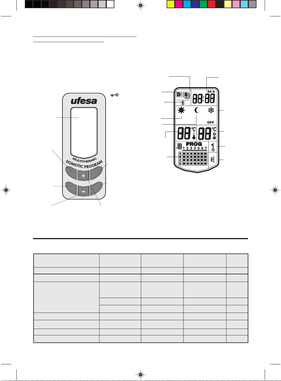
6.3. DOMOTIC PROGRAM (ET9904 - ET9906 - ET9908 -6.3. DOMOTIC PROGRAM (ET9904 - ET9906 - ET9908 -
SS
SS
6.3. DOMOTIC PROGRAM (ET9904 - ET9906 - ET9908 -
6.3. DOMOTIC PROGRAM (ET9904 - ET9906 - ET9908 -6.3. DOMOTIC PROGRAM (ET9904 - ET9906 - ET9908 ET9912) & DOMOTIC REMOTE (ET9900)ET9912) & DOMOTIC REMOTE (ET9900)
ET9912) & DOMOTIC REMOTE (ET9900)
ET9912) & DOMOTIC REMOTE (ET9900)ET9912) & DOMOTIC REMOTE (ET9900)
Connection options:Connection options:
Connection options: (Independent / Domotic Master -
Connection options:Connection options:
Slave mode)
LIQUID CRYSTAL DISPLAYLIQUID CRYSTAL DISPLAY
LIQUID CRYSTAL DISPLAY
LIQUID CRYSTAL DISPLAYLIQUID CRYSTAL DISPLAY
Description of the readings.
Only Domotic appliances are equipped with this display.
Pressing any of the six keys will switch on the light and
activate the keypad. Do not enter any further instructions.
Following 5” without instructions the light will go out
and the keypad will go to standby. In programming
mode this will take 10”
Lock / Unlock.
Maximum
Liquid crystal
.
display
Select
operating
mode
-CONFORT
-ECONOMIC
-FROST
PROTECTION
-PROG
-OFF
Access
programming
function
Decrease temperature
Increase minutes
Cancel options
Go back
SEL
P
temperature
.
limit
Accept
programs and
orders
O.K.
Configuration:
- Time
- day of the week
R
-hierarchical
position
- Option selection
Increase temperature
Increase hours
Accept options
Advance
24H clock.
Mode
Slave unit
Master
unit mode
Independent
mode
Comfort
mode
Economy
mode
Actual
temperature
thermometer
Program
indicator
Day/program
Each time a key is pressed the screen will light up and activate
the keypad. It will remain active for 10 seconds after having
pressed the last key. 15 seconds in programming mode
Always
displayed if the
appliance is
plugged into the
mains supply.
Even when OFF
Frost protect
position.
Programmed
temperature.
Controls locked
Appliance
warming up
The various types of UFESA panel heaters incorporate the following functions:
REMOTEREMOTE
REMOTE
PROGRAMMING FUNCTIONSPROGRAMMING FUNCTIONS
PROGRAMMING FUNCTIONS
PROGRAMMING FUNCTIONSPROGRAMMING FUNCTIONS
- Frost protect position.- Frost protect position.
- Frost protect position.
- Frost protect position.- Frost protect position.
- Comfort/Economy position:- Comfort/Economy position:
- Comfort/Economy position:
- Comfort/Economy position:- Comfort/Economy position:
- Domotic position:- Domotic position:
- Domotic position:
- Domotic position:- Domotic position:
- Independent position:- Independent position:
- Independent position:
- Independent position:- Independent position:
- Slave unit position:- Slave unit position:
- Slave unit position:
- Slave unit position:- Slave unit position:
- Master unit position:- Master unit position:
- Master unit position:
- Master unit position:- Master unit position:
- Timer function:- Timer function:
- Timer function:
- Timer function:- Timer function:
- Weekly programming:- Weekly programming:
- Weekly programming:
- Weekly programming:- Weekly programming:
- Electronic control- Electronic control
- Electronic control
- Electronic control- Electronic control
- Telephone control- Telephone control
- Telephone control
- Telephone control- Telephone control
ELECTRONICELECTRONIC
ELECTRONIC
ELECTRONICELECTRONIC
ET9704-ET9706-ET9708-ET9712ET9704-ET9706-ET9708-ET9712
ET9704-ET9706-ET9708-ET9712
ET9704-ET9706-ET9708-ET9712ET9704-ET9706-ET9708-ET9712
XX
X
XX
XX
X
XX
XX
X
XX
XX
X
XX
DIGITALDIGITAL
DIGITAL
DIGITALDIGITAL
ET9804-ET9806-ET9808-ET9812ET9804-ET9806-ET9808-ET9812
ET9804-ET9806-ET9808-ET9812
ET9804-ET9806-ET9808-ET9812ET9804-ET9806-ET9808-ET9812
XX
X
XX
XX
X
XX
XX
X
XX
XX
X
XX
XX
X
XX
XX
X
XX
DOMOTICDOMOTIC
DOMOTIC
DOMOTICDOMOTIC
ET9904-ET9906-ET9908-ET9912ET9904-ET9906-ET9908-ET9912
ET9904-ET9906-ET9908-ET9912
ET9904-ET9906-ET9908-ET9912ET9904-ET9906-ET9908-ET9912
XX
X
XX
XX
X
XX
XX
X
XX
XX
X
XX
XX
X
XX
XX
X
XX
XX
X
XX
REMOTEREMOTE
ET9900ET9900
ET9900
ET9900ET9900
XX
X
XX
XX
X
XX
XX
X
XX
XX
X
XX
XX
X
XX
XX
X
XX
XX
X
XX
XX
X
XX
20
L.I. ET9704… 11/3/05, 16:5620

7. ON FUNCTION7. ON FUNCTION
7. ON FUNCTION
7. ON FUNCTION7. ON FUNCTION
7.1 ELECTRONIC7.1 ELECTRONIC
7.1 ELECTRONIC
7.1 ELECTRONIC7.1 ELECTRONIC
7.1.1. Definition7.1.1. Definition
7.1.1. Definition
7.1.1. Definition7.1.1. Definition
(ET9704-ET9706-ET9708-ET9712)
The electronic thermostats for the basic electronic control with which this type of UFESA Panel Heater is
equipped are controlled by a special integrated circuit
sensitive to changes of 0.1ºC The temperature sensor is
located on the air inlet flow.
Temperature can be selected by turning the
corresponding control knob. Thanks to a pilot lamp that
comes on when the appliance is warming up ( ) we
can gauge the ideal temperature by balancing the
temperature setting with the light coming on and off.
These models also have a Comfort/Economy mode
switch.
7.1.2. Operation7.1.2. Operation
7.1.2. Operation
7.1.2. Operation7.1.2. Operation
2.1. Operating mode selection2.1. Operating mode selection
2.1. Operating mode selection
2.1. Operating mode selection2.1. Operating mode selection
Pressing the rocker switch switches the unit ON or OFF
The pilot lamp lights up to indicate the ON position.
2.2. Temperature selection2.2. Temperature selection
2.2. Temperature selection
2.2. Temperature selection2.2. Temperature selection
Turning the control knob in a clockwise direction
increases the temperature.
To select the ideal temperature turn the control knob
around to the maximum temperature position As soon
as it reaches the ideal temperature, whether by personal judgement or with the help of a thermometer, turn
the control knob back slowly until the corresponding
pilot lamp switches off. We can always make some fine
adjustments afterwards.
2.3. Frost protect function.2.3. Frost protect function.
2.3. Frost protect function.
2.3. Frost protect function.2.3. Frost protect function.
With the appliance switched ON, turn the control knob
in an anticlockwise direction back to the ( ) position.
The appliance will come on automatically when the
ambient temperature drops to 5ºC.
2.4. Comfort/Economy mode selection.2.4. Comfort/Economy mode selection.
2.4. Comfort/Economy mode selection.
2.4. Comfort/Economy mode selection.2.4. Comfort/Economy mode selection.
Pressing the corresponding key changes from one
operating mode to the other. The Economy (
) mode
lowers the set point temperature by approximately 3.5ºC
with respect to the set point temperature in the Comfort
( ) mode without having to change the thermostat
setting.
DEFINITION OF TERMSDEFINITION OF TERMS
DEFINITION OF TERMS
DEFINITION OF TERMSDEFINITION OF TERMS
-Frost protect position-Frost protect position
-Frost protect position (
-Frost protect position-Frost protect position
).
Whenever we are away from the house on holidays,
weekends or any other reason, a sharp drop in
temperature can freeze pipes, plants, etc.
In such cases the ( ) function can be used to keep the
temperature between +5ºC and +7ºC approx. with very
little power consumption.
- Comfort (- Comfort (
- Comfort (
- Comfort (- Comfort (
) / Economy () / Economy (
) / Economy (
) / Economy () / Economy (
) position) position
) position:
) position) position
The ( ) selection drops the set temperature by 3.5ºC.
Which means that we can use this option during the
night and then bring it back up to the set temperature
by selecting the ( ) option.
It can also be used when we are not at home, keeping
the house warm but using less electricity.
- Domotic position:- Domotic position:
- Domotic position: (Only on Digital timer and Domotic
- Domotic position:- Domotic position:
models)
designed to
addition to this, the
to both
Digital timer and DomoticDigital timer and Domotic
Digital timer and Domotic appliances are
Digital timer and DomoticDigital timer and Domotic
receivereceive
receive a Gifam system domotic signal. In
receivereceive
DomoticDomotic
Domotic appliances are designed
receivereceive
receive and
receivereceive
DomoticDomotic
transmittransmit
transmit a Gifam system domotic
transmittransmit
signal. This output signal allows start / stop times to be
programmed based on the day, night and frost
protection settings of the appliance itself and its slave
units.
CONNECTION MODES – HIERARCHICAL POSITIONCONNECTION MODES – HIERARCHICAL POSITION
CONNECTION MODES – HIERARCHICAL POSITION
CONNECTION MODES – HIERARCHICAL POSITIONCONNECTION MODES – HIERARCHICAL POSITION
- Independent position:- Independent position:
- Independent position:
- Independent position:- Independent position:
The appliance operates in independent mode;
neither receiving orders as a slave unit or transmitting
Domotic signals as a master unit.
- Slave unit position:- Slave unit position:
- Slave unit position:
- Slave unit position:- Slave unit position:
The appliance acts as a slave unit following Domotic
orders or functions issued by a Master unit.
- Master unit position:- Master unit position:
- Master unit position:
- Master unit position:- Master unit position:
The appliance carries out functions to control all
other appliances that are connected to it, whether
they be of a digital or domotic type
NOTE:NOTE:
NOTE:
NOTE:NOTE:
Only one Domotic type panel heater can act as a Master
unit within an installation.
The remaining Domotic appliances should be set to the
slave position.
L.I. ET9704… 11/3/05, 16:5621
If more than one Domotic appliance is accidentally set
as a master unit then the remaining slave units may receive
conflicting signals which will affect operation.
21

7.2. DIGITAL TIMER7.2. DIGITAL TIMER
7.2. DIGITAL TIMER
7.2. DIGITAL TIMER7.2. DIGITAL TIMER
7.2.1. Definition7.2.1. Definition
7.2.1. Definition
7.2.1. Definition7.2.1. Definition
(ET9804-ET9806-ET9808-ET9812)
The electronic thermostats for the basic electronic control with which this type of UFESA Panel Heater is
equipped are controlled by a special integrated circuit
sensitive to changes of 0.1ºC.
The temperature probe is located on the outside of the
appliance and is designed to counterbalance the
influence of any internally generated heat.
The temperature is displayed as a two digit figure plus
an appliance warming up sign ( ) whenever the
thermostat is in the closed position.
The temperature is selected by using two push-buttons
(+ and - ) and the temperature is shown on the luminous
display panel.
There is an OFF position marked by a dot at the top lefthand side of the display, plus three manually selected
temperature status positions each with an amber
indicator and, finally, a Domo position with a blue LED
which shows if the appliance is obeying external
domotic signals issued by a master appliance (slave unit
function mode).
Selection is made by pressing the ( ) key which will
rotate it through its various positions. A prolonged press
of more than 2” will switch the appliance OFF .
The electronic control unit has a memory just in case
there is a power cut and this will remember the
temperature and function settings for as long as
necessary until the power is restored.
The TIMER and Temperature Limit programming functions
make this range fully featured and yet still simple to use.
7.2.2.Operation7.2.2.Operation
7.2.2.Operation
7.2.2.Operation7.2.2.Operation
2.1 Operating mode selection2.1 Operating mode selection
2.1 Operating mode selection
2.1 Operating mode selection2.1 Operating mode selection
With each press of the ( ) key it will roll through: Off,
Comfort, Economy, Frost protection, Domo, Off. The
selection is shown by a single pilot lamp that will light
up alongside each signal.
After 5” of inactivity it will revert back to showing the
ambient temperature, after 5” more the backlight will
dim back to standby.
2.3 Limiting maximum temperature2.3 Limiting maximum temperature
2.3 Limiting maximum temperature
2.3 Limiting maximum temperature2.3 Limiting maximum temperature
Although the thermostat has a setting range of between
+5ºC and +35ºC it is possible to limit this range by
reducing the maximum temperature down as far as
+15ºC, i.e. the temperature range can be brought down
to between +5ºC and 15ºC. This selection has a restricted
access level given that it is necessary to know the
procedure. This can also stop people from wasting
energy or, for example, killing pot plants that are susceptible to heat. The procedure is as follows:
1 Keep [-] pressed down for 5”. The selected maximum
temperature limit (35ºC by default) will appear flashing
on the screen.
2 Press [+] or [-] to adjust the limit to the desired setting.
Each press of the key will increase or decrease the setting
by 1ºC. 5” after you stop pressing these keys the
displayed value will stop flashing and be accepted, 5”
later the display will revert back showing to the ambient
temperature.
2.4. Timer function2.4. Timer function
2.4. Timer function
2.4. Timer function2.4. Timer function
This function allows you to program the appliance to switch
itself on or off with setting s from 1 to 99 hours. This dual
purpose function allows the appliance to stay warm for a
set time when we are going to bed or to switch itself on
when we are getting up or before coming home after a
weekend out.
To activate this function:
- Keep [+] pressed down for 5 seconds. A flashing [00] will
appear on the screen, unless you have already activated
the Timer function in which case the time left will be
displayed.
- Press [+] or [-] to adjust the time to the desired setting. A 5
second gap without pressing will set the value as
programmed. The screen will go back to displaying the room
temperature and the clock will begin its countdown.
- As soon as the programmed time has elapsed the
appliance will do one of these two things:
- If it is OFF, it will switch on in Comfort mode.
- If it is in Comfort, Frost protection or Domo mode, it
will switch OFF
2.2 Temperature selection2.2 Temperature selection
2.2 Temperature selection
2.2 Temperature selection2.2 Temperature selection
By pressing [+] or [-] the display light will increase,
showing the ambient temperature for 1” and then
reverting back to the selected temperature. Each press
of the [+] or [-] key will increase or decrease the
temperature by 1ºC, respectively.
22
L.I. ET9704… 11/3/05, 16:5622
7.2.3. Factory settings7.2.3. Factory settings
7.2.3. Factory settings
7.2.3. Factory settings7.2.3. Factory settings
All of the appliances leave the factory with the following
default settings:
3.1. Operating mode selection OFF
3.2. Set point temperature 20ºC
3.3. Maximum temperature limit 35ºC

7.3. DOMOTIC PROGRAM7.3. DOMOTIC PROGRAM
7.3. DOMOTIC PROGRAM
7.3. DOMOTIC PROGRAM7.3. DOMOTIC PROGRAM
7.3.1. Definition7.3.1. Definition
7.3.1. Definition
7.3.1. Definition7.3.1. Definition
(ET9804-ET9806-ET9808-ET9812)
The electronic thermostats for the basic electronic control with which this type of UFESA Panel Heater is
equipped are controlled by a special integrated circuit
sensitive to changes of 0.1ºC
The temperature probe is located on the outside of the
appliance and is designed to compensate for the
influence of any internally generated heat.
This powerful microprocessor is capable of controlling
each and every one of the appliance’s multiple functions,
which are described below:
. Hierarchical position:. Hierarchical position:
A
. Hierarchical position: This allows the appliance to
. Hierarchical position:. Hierarchical position:
be set to Master, Slave or Independent position.
B. Operating mode selection:B. Operating mode selection:
B. Operating mode selection: This allows each one of
B. Operating mode selection:B. Operating mode selection:
the Comfort ( ) , Economy ( ), Frost protection ( ) ,
Off and Prog options to be selected or deactivated.
C. Permanent programmingC. Permanent programming
C. Permanent programming: It is possible to enter up to
C. Permanent programmingC. Permanent programming
four different 24 hour programs that can be spread out
over 15 different periods throughout the day, with each
program being assigned a Comfort ( ) , Economy ( )
or Off position. We can also assign a specific program
for each day of the week. We means that we could have
one program operating Monday to Friday, another for
Saturdays and a third program for Sundays, which would
leave us with one program spare that could be used to
replace any of the other three whenever we chose.
D. Direct operation (no programming)D. Direct operation (no programming)
D. Direct operation (no programming) Either in Master
D. Direct operation (no programming)D. Direct operation (no programming)
or Independent mode. Press any key to activate the LED
Next press SEL repeatedly until the desired function,
Comfort ( ) , Economy ( ), Frost protection ( ) , Off or
Prog, appears. The chosen option will flash on and off
until we confirm it by pressing OK.
All of these selections are displayed on the liquid crystal
display, which also provides a permanent display of
the time, day of the week, ambient temperature,
selected temperature, key and warm up signal.
When set to the Master position the appliance will send
out signals, via the Domo cable, to control other
appliances connected to the system, whether these be
digital or domotic. When set to Slave mode it will carry
out the orders that it receives from another Domotic
appliance.
When set to Independent mode, the appliance will
operate normally as an isolated appliance without
influencing or being influenced by domotic signals.
7.3.2. Operation7.3.2. Operation
7.3.2. Operation
7.3.2. Operation7.3.2. Operation
The appliance leaves the factory with the light and screen
option deactivated by default, however if you wish you
can reprogram it to leave the screen and light always on
and with the keypad permanently activated.
If you do this it will no longer be necessary to first press
a key in order to light the LCD before starting any
procedure.
To activate this function, first activate the keypad (press
any key to switch the screen on) and then the sequence:
O.K. [+] SEL To disable the function press: O.K. [+] SEL.
Under normal conditions (without activating this
function) the light will go out in order to confirm a
selection or programming process However, with this
function enabled (light permanently on) confirmation
will be given by a prolonged beep.
If you decide to program in normal mode (i.e. light and
screen NOT permanently on) then remember that the
first key you press merely switches on the LCD (It has no
effect whatsoever with the programming)
E. Special functionsE. Special functions
E. Special functions For locking the controls, limiting
E. Special functionsE. Special functions
maximum temperature, silent operation and, lastly,
keeping the light and display panel switched on
permanently.
F. Energy reserve F. Energy reserve
F. Energy reserve The electronic control circuit has a
F. Energy reserve F. Energy reserve
battery-free energy reserve; so there is nothing to replace.
If there is ever a power cut the screen will switch off but
none of the programmed values will be lost and the
clock will keep running. This energy supply will last at
least 6 hours. If the energy supply does eventually run
out, all of the selected values and programs will still be
stored and it will only be necessary to reset the time
and day.
L.I. ET9704… 11/3/05, 16:5623
Below is a description of how all the functions that the
Panel Heater’s Domotic Controls work:
A. Set upA. Set up
A. Set up. This is only done once when the appliance is
A. Set upA. Set up
installed or whenever you require a new set up.
B. ClockB. Clock
B. Clock (24h). Press key R. The clock will flash. Use the
B. ClockB. Clock
[+] key to move through the hours and the [-] for the
minutes. Use O.K. to confirm the time and then the Day
1 indicator will start to flash.
C. Day of the weekC. Day of the week
C. Day of the week Use [+] and [-] to advance or go
C. Day of the weekC. Day of the week
back through the days of the week. Use O.K. to confirm
and then the D (Master) will flash.
23

D. Hierarchical status:D. Hierarchical status:
D. Hierarchical status: Use [+] and [-] to advance or go
D. Hierarchical status:D. Hierarchical status:
back through the D (Master), S (Slave) or I (Independent)
options. Press O.K. to confirm whichever hierarchical
option is flashing. If you have chosen S (Slave) the set
up will finish and the display will revert back to the normal screen. Otherwise (
E. Option selection:E. Option selection:
E. Option selection: Use [+] to activate and [-] to
E. Option selection:E. Option selection:
) will flash.
deactivate ( ). Then it goes to ( ) which starts flashing.
Use [+] to activate and [-] to deactivate. Then to ( ), to
Off and to Prog, which are all activated and deactivated
in a similar fashion. Set up is now complete and the
screen reverts back to normal.
F. ProgrammingF. Programming
F. Programming
F. ProgrammingF. Programming
F.1 Factory settingsF.1 Factory settings
F.1 Factory settings
F.1 Factory settingsF.1 Factory settings
After having activated the keypad (press any key), press
key P: Prog and everything
on line A will start to flash.
Pressing P again will move through B, C or D.
Each program, A, B, C and D, provides an option to select
different functions throughout various times of the day
until all 24:00 hours have been completed.
As soon as you have completed the last period up to
24:00 in program A, it automatically moves on to modify
the factory program B and then C and finally D.
Lets leave it on A: The clock shows 00:00 and Economy (
flashes, by press [+] it advances and pressing [-] moves
it back to Comfort ( ), Frost protection ( ) and OFF.
O.K confirms whichever option is flashing and then the
end time for this first period starts to flash.
)
All the appliance leave the factory with the following
default settings:
- Hierarchical position: D (Master):- Hierarchical position: D (Master):
- Hierarchical position: D (Master):
- Hierarchical position: D (Master):- Hierarchical position: D (Master):
- Selection status Off- Selection status Off
- Selection status Off
- Selection status Off- Selection status Off
- Set point temperature 20ºC- Set point temperature 20ºC
- Set point temperature 20ºC
- Set point temperature 20ºC- Set point temperature 20ºC
- Maximum temperature limit 35ºC- Maximum temperature limit 35ºC
- Maximum temperature limit 35ºC
- Maximum temperature limit 35ºC- Maximum temperature limit 35ºC
Program A : Monday, Tuesday, Wednesday, Thursday and
Friday
6,30 12,30 18 24
0
Program B: Saturdays
0
Program C: Sundays
0
Program D: Not assigned
0
8,30 14,30
8 12,30 19 24
9,30 17
8,30 18 24
10,30 16
6,30 18 24
8,30 16
21,30
22
21,30
21,30
If you wish to modify to the factory set programs, do
the following.
F.2 Program A set up:F.2 Program A set up:
F.2 Program A set up:
F.2 Program A set up:F.2 Program A set up:
If the appliance is already running a program then it is
advisable to exit PROG selection before entering a new
program.
Use the [+] key to move through the hours and the [-] for
the minutes, always moving upward. Use O.K to confirm
and the program will move on to the next period in
program A, which we do in the same fashion. We do
the same with all of the periods required until we reach
24:00 and confirm by pressing O.K. It now moves to
program B.
F.3. Program BF.3. Program B
F.3. Program B
F.3. Program BF.3. Program B
The same as program A. As soon as 24:00 is confirmed
it moves on to program C.
F.4. Program CF.4. Program C
F.4. Program C
F.4. Program CF.4. Program C
The same as program A and B. As soon as 24:00 is
confirmed it moves on to program C.
F.5. Program DF.5. Program D
F.5. Program D
F.5. Program DF.5. Program D
The same as program A, B and C. As soon as 24:00 is
confirmed it moves on to program assignment.
F.6. Program assignmentF.6. Program assignment
F.6. Program assignment
F.6. Program assignmentF.6. Program assignment
O.K for 24:00 in program D takes us to program
assignment. At this point it shows all of the for programs
that have been assigned. It is also possible to pass
directly to here without passing through all of the above
programming steps by pressing the P key repeatedly until
the for assigned programs appear on the display.
The will flash, if there is one, for day 1 along with the
indicator for 1. Using [+] we can lower the and with
[-] we can raise it, press O.K to confirm. Next indicator 2
will flash along with the , if there is one. Using [+], [-]
and O.K proceed as above until you reach day 7, this
final O.K will take you back to the normal screen.
F.7. RemarksF.7. Remarks
F.7. Remarks
F.7. RemarksF.7. Remarks
At any point during programming a prolonged press
(more than 2 seconds) on the O.K. key will confirm the
24
L.I. ET9704… 11/3/05, 16:5624

information on the screen, finish the programming
process and take you back to the normal screen.
1 Activate the keypad (press any key).
2 Press the sequence: O.K. [+] [-].
Similarly, if no keys are pressed for 15” the information
will be confirmed and the normal screen will reappear.
There may be days that have not been assigned a
program (OFF by default) or programs that have not been
assigned to a particular day. However, it is not possible
to assign more than one program to any one day.
G. Operating mode selectionG. Operating mode selection
G. Operating mode selection
G. Operating mode selectionG. Operating mode selection
When you press the SEL key the first option activated in
procedure 7.3.2 E will appear flashing on the screen.
Pressing SEL repeatedly will allow you to scroll through
all the options.
You can confirm whichever option is flashing by pressing
the O.K. key or by leaving it for 10”.
H. Temperature selectionH. Temperature selection
H. Temperature selection
H. Temperature selectionH. Temperature selection
Pressing any key will illuminate the screen and activate
the temperature function. Each press of the [+] or [-]
key will increase or decrease the temperature by 1ºC,
respectively. You can confirm whichever option is
shown by pressing the O.K. key or by leaving it for 10”.
I. Special functionsI. Special functions
I. Special functions
I. Special functionsI. Special functions
I.1. Maximum temperature limitI.1. Maximum temperature limit
I.1. Maximum temperature limit
I.1. Maximum temperature limitI.1. Maximum temperature limit
Although the thermostat has a setting range of between
+5ºC and +35ºC it is possible to limit this range by
reducing the maximum temperature down as far as
+15ºC, i.e. the temperature range can be brought down
to between +5ºC and 15ºC.
This selection has a restricted access level given that it is
necessary to know the procedure.
This can also stop people from wasting energy or, for
example, killing pot plants that are susceptible to heat.
The procedure is as follows:
1 Activate the keypad (press any key).
2 Next press O.K. [+] P. The maximum selectable
temperature will appear on the screen. Modify this with
the [+] or [-] keys and confirm with O.K., or by leaving it
for 10”.
I.2. Locking the controlsI.2. Locking the controls
I.2. Locking the controls
I.2. Locking the controlsI.2. Locking the controls
With the appliance locked ( ), whenever we press a
key only the screen will light up and we will be shown
the locked symbol. No operation will be permitted
unless the lock is deactivated.
To activate and deactivate this function:
The locked symbol will appear on the screen when the
lock is active.
I.3. Silent modeI.3. Silent mode
I.3. Silent mode
I.3. Silent modeI.3. Silent mode
Each time we press a key we know that it has been
pressed because each key stroke will generate a
confirmation beep.
Silent mode: You can silence the beep sound after
having activated the keypad (press any key) by pressing
the sequence O.K. [+] R. To reactivate the beep sound
just repeat the same sequence. Activate the keypad and
then O.K. [+] R.
I.4. Light and screen on permanently.I.4. Light and screen on permanently.
I.4. Light and screen on permanently.
I.4. Light and screen on permanently.I.4. Light and screen on permanently.
If you wish you can leave the light and screen on
permanently, leaving the keypad permanently active.
If you do this it will no longer be necessary to first press
a key in order to light the LED before starting any
procedure.
To activate this function, first activate the keypad (press
any key to switch the screen on) and then the sequence:
O.K. [+] SEL
To disable the function press: O.K. [+] SEL
Under normal conditions (without activating this
function) the light will go out in order to confirm a
selection or programming process However, with this
function enabled (light permanently on) confirmation
will be given by a prolonged beep.
I.5. Clock & thermometerI.5. Clock & thermometer
I.5. Clock & thermometer
I.5. Clock & thermometerI.5. Clock & thermometer
The screen will always display two important items of
information, namely the time (24h) and the temperature
(ºC) The only condition required to have this information
available is to keep the appliance plugged into the mains
supply. Regardless of whether it is OFF or in any other
position. The electricity used by this function is
insignificant.
7.3.3 Telephonic remote control (Model ET9900)7.3.3 Telephonic remote control (Model ET9900)
7.3.3 Telephonic remote control (Model ET9900)
7.3.3 Telephonic remote control (Model ET9900)7.3.3 Telephonic remote control (Model ET9900)
The ET9900 model is a Domotic model which incorporates
a telephonically operated remote control. This remote
control allows us to use a telephone in any part of the world
to control the operating modes of a Remote Domotic Heater
that has been connected to a telephone line and,
consequently, if it is acting as a Master unit, to control the
whole installation connected to it. If it is in the Independent
position then only this appliance is controlled. The remote
control will not work if the appliance is in the Slave position
or is unplugged from the m supply.
L.I. ET9704… 11/3/05, 16:5625
25

A. Telephone line connectionA. Telephone line connection
A. Telephone line connection
A. Telephone line connectionA. Telephone line connection
A two way splitter should be inserted into the telephone
line connection box. One of these we use to connect the
telephone and the other for the telephone cable with male
connectors at both ends, making sure the cable is long
enough to reach the heater. At the bottom of the control
side of the appliance there is a female connector into which
the other end of the telephone cable should be inserted.
B. UseB. Use
B. Use
B. UseB. Use
- Call the telephone number where the Remote Domotic
Heater is connected. The heater will wait for 7 rings before
answering the call, this is to allow anyone who may be in
the house to answer the phone normally. After 7 rings the
appliance will answer the call and the procedure will be
activated by identifying itself as:
REMOTE CONTROL
- Next, the caller will have to press keys [1] and [2], one
directly after the other. The procedure will not continue if
this code is not entered. When your user code has been
accepted you will receive the following information:
STATUS: This will indicate the one that corresponds to the
following: OFF / COMFORT / ECONOMY / PROGRAM
8. IN THE EVENT OF A POWER CUT8. IN THE EVENT OF A POWER CUT
8. IN THE EVENT OF A POWER CUT
8. IN THE EVENT OF A POWER CUT8. IN THE EVENT OF A POWER CUT
Electronic. Electronic.
Electronic. The appliance will be unusable but will
Electronic. Electronic.
reconnect itself as soon as the power is re-established.
Digital. The appliance will be unusable but will reconnect
itself as soon as the power is re-established. All of the
settings will remain the same, except for the Timer function
which, if was originally activated, will be cancelled with
the hour counter resetting to [00].
Domotic. Domotic.
Domotic. The appliance will be unusable but will reconnect
Domotic. Domotic.
itself as soon as the power is re-established.
When the power cut is relatively short, e.g. due to a storm,
the appliance will use a device THAT DOES NOT REQUIRE
A BATTERY or any component that needs changing, in order
to keep the clock running and remember all of the selections
and programs, even though the screen switches itself off
for while.
If the power cut is quite long then the clock settings and
part of the programming will be lost and it will be necessary
to reset the time and then reprogram.
Then the possible alternatives:
OPTIONS:
[2] OFF / [3] PROGRAM / [4] ECONOMY / [5] COMFORT
- You should choose the option by pressing the
corresponding telephone key, which will be confirmed
verbally by the appliance:
NEW STATUS:
If you are not happy with it you can change the option as
many times as you like, and in each case the new status will
be confirmed.
- When you are happy with your choice, confirm it by
pressing the [1] key. The appliance will accept it by stating:
(whatever it is, e.g. OFF)
REMOTE CONTROL AT YOUR SERVICE
- Hang up.
Important note: The remote control cannot be used
simultaneously on a line with other automatic answering
devices such as an answering machine, fax or anything else
that answers the phone before the remote control.
26
9. PROTECTION AGAINST OVERHEATING9. PROTECTION AGAINST OVERHEATING
9. PROTECTION AGAINST OVERHEATING
9. PROTECTION AGAINST OVERHEATING9. PROTECTION AGAINST OVERHEATING
The appliance is designed to transmit heat via convection
and radiation. This function may be hindered if the
appliance is covered over, totally or partially, with damp
or dry clothes or any other object. This can also cause
the appliance to overheat.
Nevertheless, the appliance is equipped with a safety
device that will disconnect it should it ever overheat.
The appliance will come back on automatically as soon
as the problem is corrected. Apart from affecting normal operation, repeated overheating can cause damage
which is not covered by the guarantee. For this reason
it is advisable NEVER TO COVER the appliance.
10. PERIODIC MAINTENANCE10. PERIODIC MAINTENANCE
10. PERIODIC MAINTENANCE
10. PERIODIC MAINTENANCE10. PERIODIC MAINTENANCE
The appliance does not require any periodic
maintenance of a technical nature.
It is only necessary to clean it from time to time, which
can be done with a vacuum cleaner fitted with a soft
brush. You can also wipe it down with a damp cloth or
use a neutral soap to remove any accidental stains.
L.I. ET9704… 11/3/05, 16:5626

SS
SS
SS
SS
SSSSSSSSSS
SS
Light and screen activated
SEL O.K.
P
O.K.
R
SEL
O.K.
SEL
Significance of the icon
Press any key to activate
the keypad.
SEL O.K.
P
R
Configuration
SEL O.K.
P
R
Option
selection
Programming
SEL O.K.
P
R
Prog. A
Time
Advance
minutes
O.K.
Day
R
Advance
hours
YES NO YES NO YES NO YES NO YES NO
Only the modes pressed down will be selected.
P
Advance
days
1= Monday
2= Tuesday
3...
Advance mode
Advance hours
Advance minutes
O.K.
Significance of the icons
O.K.
O.K.
Hierarchical
position.
D = Master
S = Slave
I = Independent
O.K.
Advance
End
Confirm
and/or
advance
position
00:00
06:30 08:30 12:30 14:30 18:00 21:30 24:00
O.K.
O.K.
O.K.
O.K.
O.K.
O.K.
Prog. B
Same procedure as A
O.K.
O.K.
O.K.
O.K.
O.K.
O.K.
O.K.
CD
Program assignment
O.K.
O.K.
O.K.
O.K.
27
L.I. ET9704… 11/3/05, 16:5627

SS
SS
SS
SS
Program assignment
SSSSSS
SS
SS
SS
From program D
Direct
SEL O.K.
P P P P P
P
R
Start
Mode selection
Set point temperature
Program
assignment
O.K. O.K. O.K.
Example 2 pre-selections
SEL O.K.
P
SEL
SEL
SEL
O.K.
R
Example 3 pre-selections
SEL O.K.
P
SEL SEL SEL
R
SEL
O.K.
Maximum temperature limit
O.K.
End
+1ºC
SEL O.K.
P
R
O.K.
SEL O.K.
P
R
-1ºC
Silent mode
SEL O.K.
Bip Bip
P
SEL O.K.
Bip Bip
P
R
O.K.
R
O.K.
R
R
O.K.
Locking the controls
SEL O.K.
P
R
P
+1ºC
O.K.
-1ºC
O.K.
O.K.
28
L.I. ET9704… 11/3/05, 16:5728
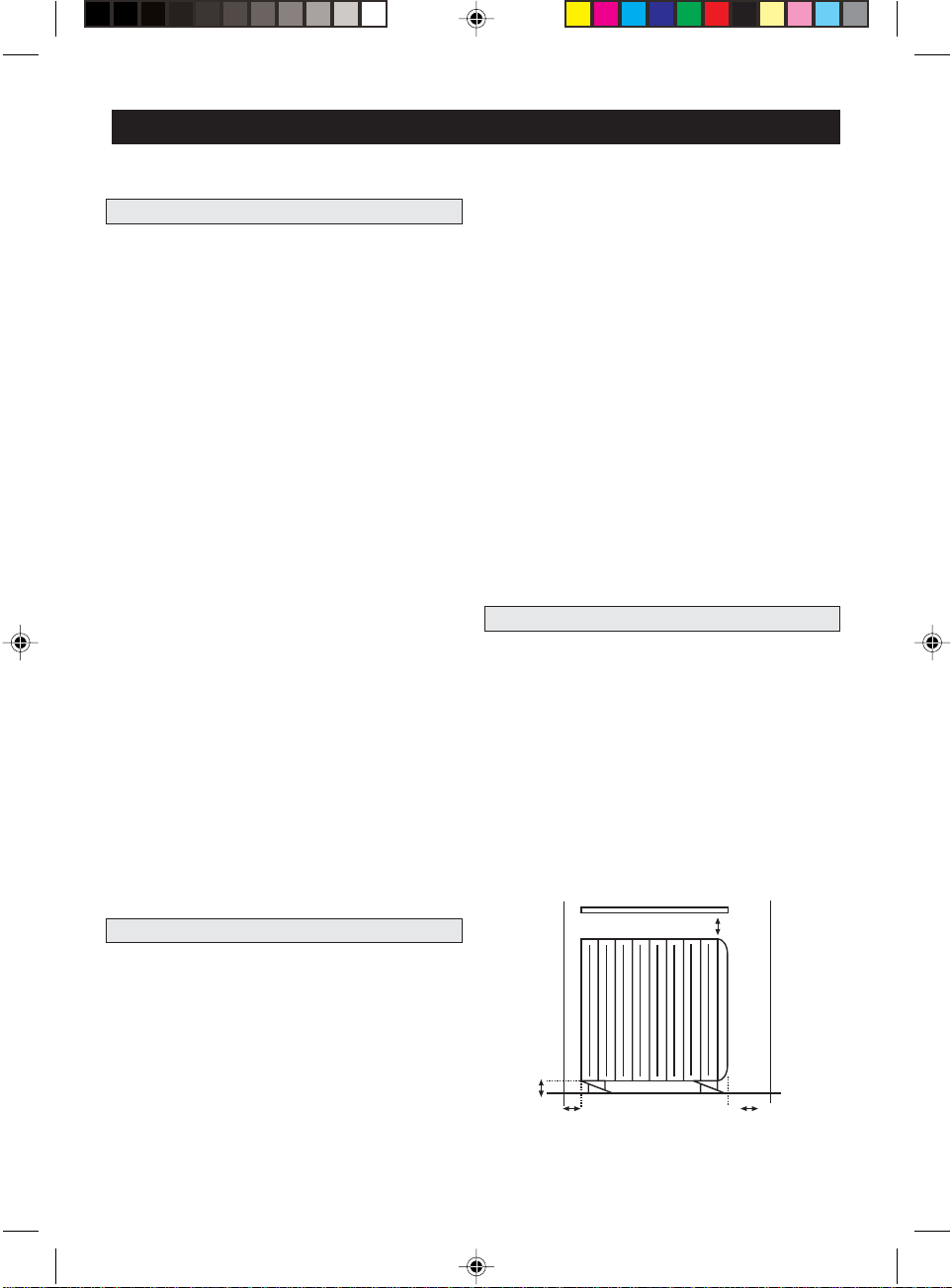
FRANÇAIS
1. PRÉCAUTIONS1. PRÉCAUTIONS
1. PRÉCAUTIONS
1. PRÉCAUTIONS1. PRÉCAUTIONS
•La garantie ne couvre pas les dommages découlant du
non-respect des indications figurant dans la présente
notice.
•Vérifiez si la tension du courant électrique
correspondant bien à celle indiquée sur la plaque des
caractéristiques.
•L’utilisation de radiateurs électriques est interdite en
présence de gaz, produits explosifs ou inflammables.
•Le cordon de branchement et aucun autre objet ne
doivent entrer en contact avec l’appareil.
•Ne poser sur l’appareil ni objets ni linge à sécher.
•Étant donné que les surfaces de l’émetteur risquent
parfois d’être chaudes, il faudra tenir l’appareil à l’écart
des enfants qu’il faudra d’ailleurs surveiller.
•Ne jamais installer l’appareil sous une prise de courant
électrique.
•Avant d’effectuer une opération sur l’appareil, il faudra
le débrancher du courant électrique. En cas de
fonctionnement défectueux faire appel à un Service
Technique Agréé (voir feuille ci-jointe).
•Le coût de l’installation de cet appareil n’est pas
compris dans le prix de vente au public. Cette installation
pourra être réalisée par un Service Technique Agréé.
•Si vous souhaitez réaliser vous-même cette installation
vous devrez suivre les instructions indiquées dans la
présente notice, cependant tout dommage subi par
l’appareil suite à une installation NON APPROPRIÉE
annule la garantie du produit.
•Cet appareil de chauffage doit être rempli d’une
quantité précise d’huile spéciale. Seuls le fabricant ou
son service après-vente sont habilités à effectuer les
réparations qui demandent l’ouverture du réservoir à
huile. En cas de fuite, faire appel à ces derniers.
•L’utilisateur de cet appareil est tenu de respecter la
réglementation relative à l’élimination des huiles des
appareils de chauffage hors d’usage.
2. CHOIX DU LIEU D’INSTALLATION DE L’APPAREIL2. CHOIX DU LIEU D’INSTALLATION DE L’APPAREIL
2. CHOIX DU LIEU D’INSTALLATION DE L’APPAREIL
2. CHOIX DU LIEU D’INSTALLATION DE L’APPAREIL2. CHOIX DU LIEU D’INSTALLATION DE L’APPAREIL
Il s’agit d’une décision très importante qui doit être prise
en connaissance de cause, appareil par appareil. Il serait
vraiment dommage de rater
UFESAUFESA
UFESA à cause d’un emplacement mal choisi ou d’une
UFESAUFESA
mauvaise fixation.
l’Installation de Chauffagel’Installation de Chauffage
l’Installation de Chauffage
l’Installation de Chauffagel’Installation de Chauffage
Dans la mesure du possible, ne pas placer non plus
l’appareil dans des coins mais le plus au milieu possible,
à l’écart de portes et de fenêtres. Il est préférable de
choisir un mur long, cependant, il est toujours des
exceptions et si par exemple, vous n’envisagez pas
d’installer d’appareils de chauffage dans le couloir
contigu, en installant l’appareil près de la porte, la chaleur
pourra alors « passer » et chauffer également le couloir.
L’installation de l’appareil sous une fenêtre fait également
partie des exceptions. Il s’agit d’une solution souvent
utilisée et également conseillée si on ne dispose pas
d’autres murs dégagés. Ne pas oublier cependant que
les fenêtres favorisent dans une certaine mesure, les
pertes de chaleur. L’appareil doit être installé de façon
à ce que ni les interrupteurs ni les boutons ne puissent
être touchés par une personne qui se trouve dans la
baignoire ou sous la douche.
Ne pas installer l’appareil sous une prise de courantNe pas installer l’appareil sous une prise de courant
Ne pas installer l’appareil sous une prise de courant
Ne pas installer l’appareil sous une prise de courantNe pas installer l’appareil sous une prise de courant
électrique.électrique.
électrique.
électrique.électrique.
3. FIXATION AU MUR3. FIXATION AU MUR
3. FIXATION AU MUR
3. FIXATION AU MUR3. FIXATION AU MUR
Après avoir choisi le lieu d’installation conformément
aux indications données au chapitre précédent, faire
comme indiqué ci-dessous :
1. Placez l’appareil à sa place : un peu plus à droite…
un peu plus haut….., etc. Pour ce faire, nous vous
suggérons d’utiliser deux paires de cales triangulaires
(voir figure 1) ou tout autre objet comme par exemple
des livres, des papiers, des boîtes en carton, etc (figure2). De toute façon, il faudra respecter des distances
minimales comme indiqué sur la figure.
Étagère éventuelle
Mur ou
objet plus
près de la
gauche
Mínimun 150 mm
Mur ou
objet plus
près de la
droite
Nous allons donc commencer par l’emplacement.
Choisir un mur dégagé, sans meubles et avec la place
suffisante pour installer l’appareil. Éviter également la
proximité de meubles, rideaux et autres appareils.
L.I. ET9704… 11/3/05, 16:5729
Mínimun
150 mm
Mínimun 100mm
Mínimun 250 mm
(côté des boutons)
29
 Loading...