

Ubiquiti Edge Pro ERPro-8, EdgeRouter ER-8, am-v5g-ti, airMAX AM-V2G-Ti, AM-M-V5G-Ti Quick Start Manual
...
8-Port Router
with 2 Combination
SFP/RJ45 Ports
Model: ERPro-8
Introduction
Thank you for purchasing the Ubiquiti Networks®
EdgeRouter
™
PRO, which is part of the EdgeMAX® platform.
Formore information, visit www.ubnt.com/edgemax
This Quick Start Guide is designed to guide you through
installation and show how to access the EdgeOS™
Configuration Interface. This guide also includes the warranty
terms and is for use with the EdgeRouter PRO, modelERPro-8.
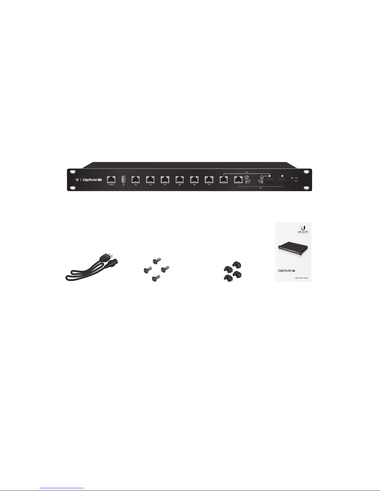
Package Contents
EdgeRouter PRO
8-Port Router
with 2 Combination
SFP/RJ45 Ports
Model: ERPro-8
Power Cord Mounting Screws
(#10-32 x 5/8", Qty. 4)
Cage Nuts
(#10-32 x 5/8", Qty. 4)
Quick Start
Guide
TERMS OF USE: All Ethernet cabling runs must use CAT5 (or above). It is the customer’s
responsibility to follow local country regulations, including operation within legal frequency
channels, output power, indoor cabling requirements, and Dynamic Frequency Selection
(DFS) requirements.
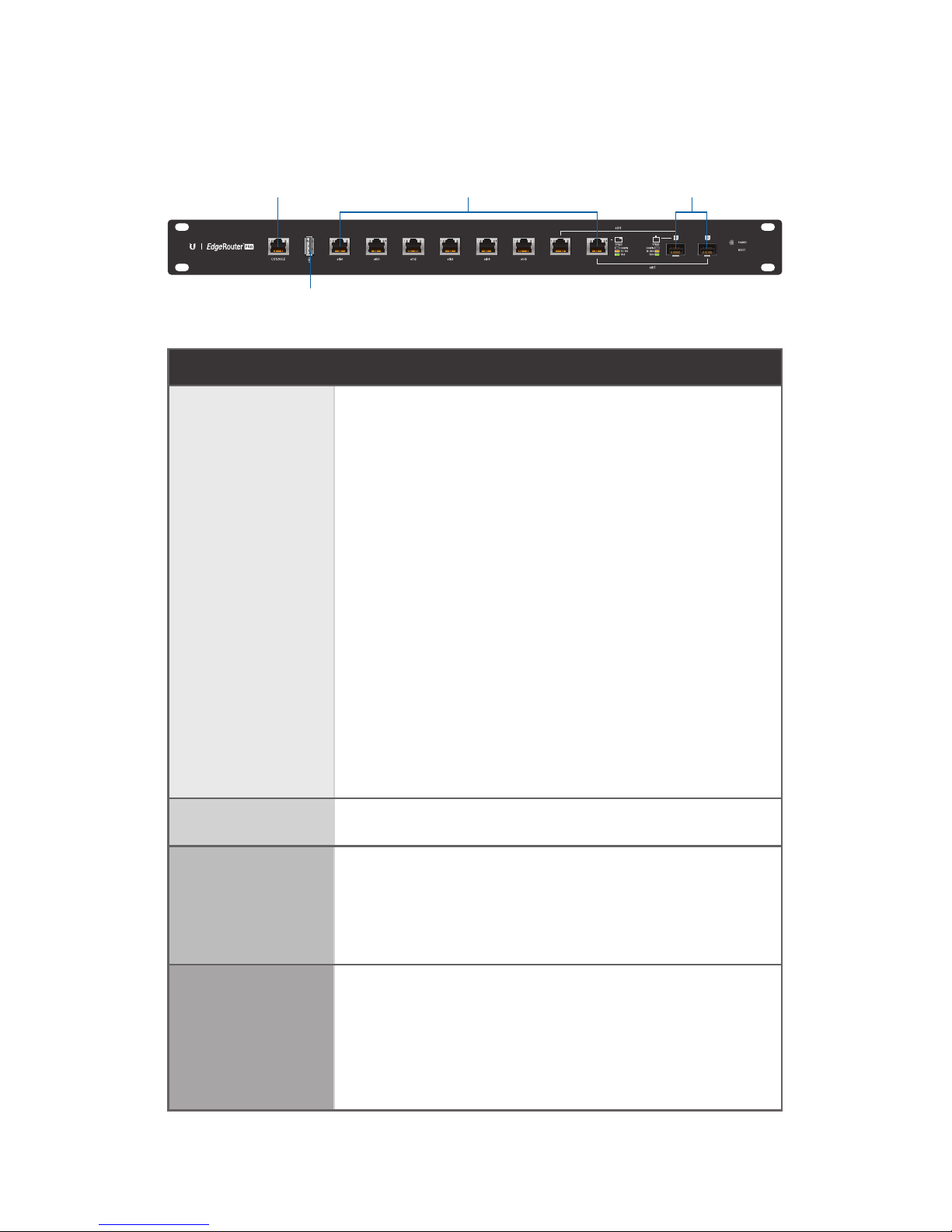
Hardware Overview
Front Panel Ports
Console
RJ45 (eth0-eth7)
SFP (eth6-eth7)
USB
Interface Description
Console
RJ45 serial console port for Command
Line Interface (CLI) management. Use an
RJ45-to-DB9, serial console cable, also
known as a rollover cable, to connect the
Console port to your computer. (If your
computer does not have a DB9 port, then
you will also need a DB9 adapter.) Then
configure the following settings as needed:
• Baud rate 115200
• Data bits 8
• Parity NONE
• Stop bits 1
• Flow control NONE
USB Reserved for future use.
RJ45
(eth0-eth7)
RJ45 ports support 10/100/1000 Ethernet
connections. RJ45 port eth6 or eth7 is
active only if the corresponding SFP port
is empty.
SFP
(eth6-eth7)
SFP ports are hot-swappable and support
100 Mbps or Gigabit fiber SFP modules. If
an SFP module is plugged in, then the SFP
port is active, and the corresponding RJ45
port is deactivated.
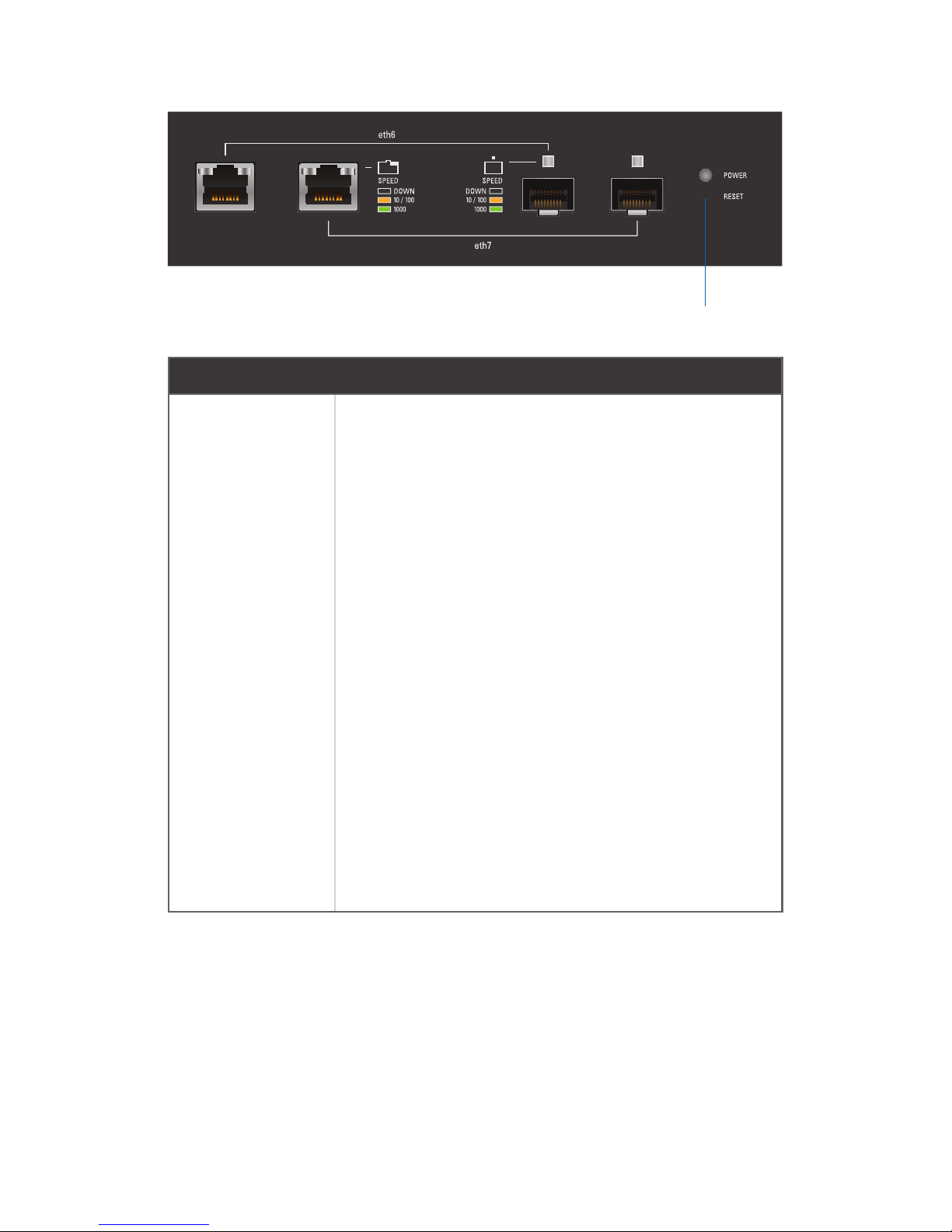
Front Panel Button
Reset
Button Description
Reset
There are two methods to reset the
EdgeRouter PRO to factory defaults:
• Runtime reset (recommended) The
EdgeRouter PRO should be running
after bootup is complete. Press and hold
the Reset button for about 10seconds
until the right LED on RJ45 port eth7
starts flashing and then becomes solidly
lit. After a few seconds, the LED will
turn off, and the EdgeRouter PRO will
automatically reboot.
• Power-on reset Disconnect the Power
Cord from the EdgeRouter PRO. Press and
hold the Reset button while connecting
the Power Cord to the EdgeRouter PRO.
Keep holding the button until the right
LED on RJ45 port eth7 starts flashing and
then stops flashing after a few seconds.

Front Panel LEDs
The LEDs on the left side of the RJ45 ports are not used at this
time. Below is a description of the other LEDs:
PowerSFP: Speed/Link/ActRJ45: Speed/Link/Act
LED State Status
RJ45 (eth0-7)
Speed/
Link/Act
Off No Link
Amber
Link Established at
10/100Mbps
Amber Flashing
Link Activity at
10/100Mbps
Green
Link Established at
1000Mbps
Green Flashing
Link Activity at
1000Mbps
SFP (eth6-7)
Speed/
Link/Act
Off No Link
Amber
Link Established at
10/100Mbps
Amber Flashing
Link Activity at
10/100Mbps
Green
Link Established at
1000Mbps
Green Flashing
Link Activity at
1000Mbps
Power
White
EdgeRouter PRO is
poweredon.
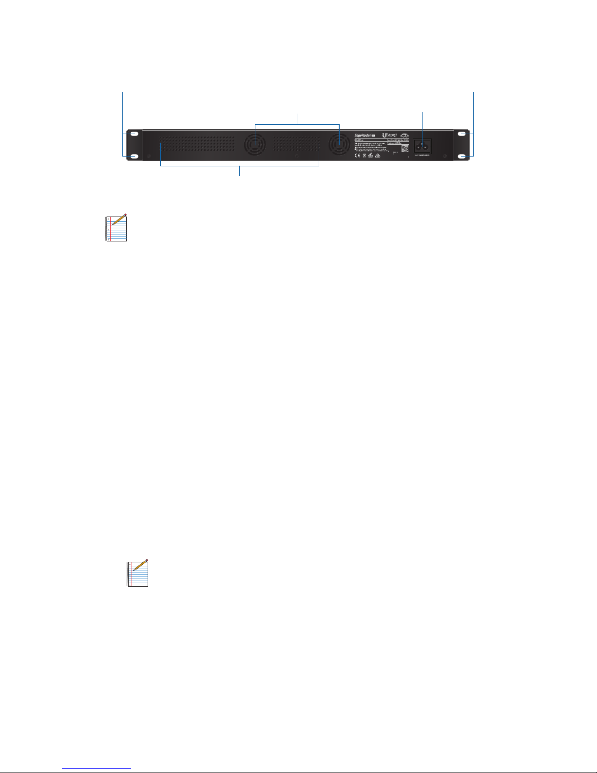
Back Panel
Mounting Holes
Power
Ventilation Holes
Mounting Holes
Fans
Note: There are additional ventilation holes on the sides
of the EdgeRouter PRO.
Installation Requirements
• Phillips screwdriver
• Standard-sized, 19" wide rack with a minimum of 1U height
available
• For indoor applications, use Category 5 (or above) UTP
cabling approved for indoor use.
• For outdoor applications, shielded Category 5 (or above)
cabling should be used for all wired Ethernet connections
and should be grounded through the AC ground of the
power supply.
We recommend that you protect your outdoor networks
from the most brutal environments and devastating ESD
attacks with industrial-grade shielded Ethernet cable,
TOUGHCable™, from Ubiquiti Networks. For more details,
visit: www.ubnt.com/toughcable
Note: Although the cabling can be located outdoors,
the EdgeRouter PRO itself should be housed inside a
protective enclosure.
 Loading...