

Ubiquiti AF-5G34-S45 operation manual
5 GHz, 34 dBi Slant 45
Antenna for airFiber
Model: AF-5G34-S45
®

Introduction
Thank you for purchasing the Ubiquiti Networks® 5GHz,
34dBi Slant 45 Polarity Antenna for airFiber®. This Quick Start
Guide is designed to guide you through the installation of the
antenna. This Quick Start Guide also includes the warranty
terms and is for use with the antenna modelAF‑5G34‑S45.
Package Contents
Dish Reflector Antenna Feed Mounting Bracket
Protective
Shroud
Elevation Rod M12x180 Carriage Bolts
TERMS OF USE: Ubiquiti radio devices must be professionally installed. Shielded Ethernet
cable and earth grounding must be used as conditions of product warranty. TOUGHCable
is designed for outdoor installations. It is the customer’s responsibility to follow local country
regulations, including operation within legal frequency channels, output power, and Dynamic
Frequency Selection (DFS) requirements.
Pole Clamps
(Qty. 2)
M10x25 Carriage Bolts
(Qty. 3)
Stabilizer Brackets
(Qty. 2)
(Qty. 4)
M4 Bolts
(Qty. 6)
RF Cables
M10x100 Bolts
(Qty. 2)
5 GHz, 34 dBi Slant 45
®
Antenna for airFiber
Model: AF-5G34-S45
Quick Start
Guide
(Qty. 2)
™

Installation Requirements
• airFiber AF‑5X radio (sold separately)
• Phillips #1 screwdriver
• 16 mm wrench
• 24 mm wrench
• Mounting point:
• At least 1 m below the highest point on the structure
• For tower installations, at least 3 m below the top of
the tower
• Shielded Category 6 (or above) cabling should be used for
all wired Ethernet connections and should be grounded
through the AC ground of the PoE.
Hardware Overview
Elevation Rod
Pole Clamp
Protective Shroud
Mounting Bracket
Pole Clamp
Stabilizer Brackets
Fully Assembled Back View

Installation
Important: Handle the Dish Reflector with care.
Deformations in its shape may reduce the antenna's
effectiveness.
1. Each M4 Bolt includes a lock washer. Remove these and use
them to secure the bolts when assembling.
2. The Dish Reflector and Antenna Feed are keyed so the
Antenna Feed can only be installed in a single orientation.
Attach the Antenna Feed to the Dish Reflector in the
following steps:
a. Line up the alignment pin on the Dish Reflector with the
hole on the Antenna Feed.
b. Insert the six M4 Bolts into the Antenna Feed and Dish
Reflector.
c. Tighten the six M4 Bolts.
Important: Do NOT handle the antenna by the Antenna
Feed once the feed is attached.
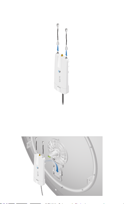
3. Attach the RF Cables to the connectors labeled Chain 0 and
Chain 1 on the airFiber radio.
4. Attach the airFiber radio to the Dish Reflector.
a. Align the mounting tabs on the back of the airFiber
radio with the airFiber radio mount located below the
Antenna Feed.
b. Slide the airFiber radio down to lock it into place.
5. Attach the other end of the RF Cables to the RF connectors
on the airFiber radio in this combination: +45° to Chain0
and -45° to Chain 1. Then slide the jackets over the RF
connectors to protect them.
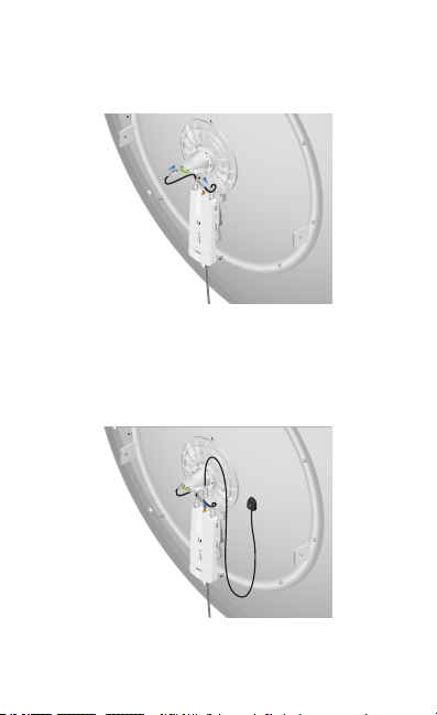
6. Attach the external GPS antenna (included with the airFiber
radio) to the RF connector labeled GPS on the airFiber
radio. Slide the jacket over the RF connector to protect it.
Then place the magnetic external GPS antenna on the Dish
Reflector (this is temporary; you will mount the external
GPS antenna last).
*640-00171-02*
640-00171-02

7. Attach the Protective Shroud.
a. Align the arrow on the top of the shroud with the short
hash mark on the Dish Reflector.
b. Rotate the shroud clockwise until it aligns with the long
hash mark to lock into place.
8. The Elevation Rod includes washers and nuts. Remove one
flat washer, one spring lock washer, and one nut. Use them
to secure the Elevation Rod when assembling.
9. Attach the Elevation Rod to the Mounting Bracket.
a. Insert the Elevation Rod into the Mounting Bracket.
b. Secure the Elevation Rod with the flat washer, spring
lock washer, and nut.

10. Each M12x180 Carriage Bolt includes a flat washer, spring
lock washer, and nut. Remove these and use them to
secure the bolts when assembling in step 16.
11. Insert the four M12x180 Carriage Bolts into the Mounting
Bracket.
 Loading...