


 Loading...
MX4428
MXP ENGINEERING / TECHNICAL MANUAL
|
MX4428 PRODUCT MANUAL |
|
|
|
VOLUME 11 |
|
|
|
Document Number: LT0273 |
|
|
|
|
|
|
|
Issue 1.5; 24 March 2006 |
|
|
|
|
|
|
|
- APPROVALS - |
|
|
|
|
|
|
AUSTRALIAN STANDARD AS4428.1 |
|
|
|
- SSL Listing Number ....................................................................................... |
afp1446 |
||
NEW ZEALAND STANDARD NZS4512-1997 (INCL AMDT 1 & 2) |
|
|
|
- FPA (NZ) Listing number ................................................................................. |
|
VF/117 |
|
AS/NZS 3548 1995 CLASS A |
|
|
|
|
|
|
|
|
|
|
|
The 4100MXP is a product of
Tyco Safety Products
211 Maces Road
Christchurch 8030
NEW ZEALAND
Phone +64-3-389 5096
Fax +64-3-389 5938
COPYRIGHT (C) 2003,2004
Information contained in this document is subject to copyright, and shall not be reproduced in any form whatsoever, without the written consent of Tyco Services Fire & Safety.
Information contained in this document is believed to be accurate and reliable, however Tyco Services Fire & Safety reserves the right to change the content without prior notice.

MX4428 MXP Engineering /Technical Manual |
Document: LT0273 |
NON-DISCLOSURE AGREEMENT
Tyco (THE COMPANY) and the User of this/these document(s) desire to share proprietary technical information concerning electronic systems.
For this reason the company is disclosing to the User information in the form of this/these document(s). In as much as the company considers this information to be proprietary and desires that it be maintained in confidence, it is hereby agreed by the User that such information shall be maintained in confidence by the User for a period of TEN YEARS after the issue date and only be used for the purpose for which it was supplied.
During this period, the User shall not divulge such information to any third party without the prior written consent of the company and shall take reasonable efforts to prevent any unauthorised disclosure by its employees. However, the User shall not be required to keep such information in confidence if it was in their possession prior to its receipt from the company; if it is or becomes public knowledge without the fault of the User; or the information becomes available on an unrestricted basis from a third party having a legal right to disclose such information.
The User's receipt and retention of this information constitutes acceptance of these terms.
This information is copyright and shall not be reproduced in any form whatsoever.
END USER LIABILITY DISCLAIMER
The MX4428 Fire Indicator Panel provides a configuration programming facility, which may be accessed via a programming terminal using a password. Because this programming facility allows the user to define in detail the operation of the MX4428 System being customised, changes may be made by the user that prevent this installation from meeting statutory requirements.
The Company, therefore cannot accept any responsibility as to the suitability of the functions generated by the user using this programming facility.
|
|
|
AMENDMENT LOG |
21 |
March 01 |
Issue 1.0 |
Original |
24 |
April 03 |
Issue 1.1 |
Updated DIM800 Compatibility, added VLC800, LPS800, Alarm |
|
|
|
Tests |
11 |
March 04 |
Issue 1.2 |
DIM800 with s/c fault option. Added "specs", noted source of |
|
|
|
MXPPROG, updated MXP software version history. |
28 |
January 05 |
Issue 1.3 |
Added requirements for AS1670.1. Noted DIM800 supply |
|
|
|
supervision threshold is not adjustable. Added MIM800 max cable |
|
|
|
length on inputs to its specs. Updated Table 3-2. Added 5B, |
|
|
|
replaced 814IB with 5BI. |
|
|
|
Noted MkII Sounder Base has AS2220 and ISO tones. Added note |
|
|
|
re acceptable type mismatches. Added reference to software |
|
|
|
version 1.12. |
28 |
October 05 |
Issue 1.4 |
Added 614CH, 614I, 614P, System Sensor 885WP-B detectors to |
|
|
|
Table 3-4. |
24 |
March 06 |
Issue 1.5 |
Added 614T Section 3.20.3. Added 814P Section 3.9, etc. Added |
|
|
|
Loop Filter Board, Chapter 10. |
TRADEMARKS
VESDA is a registered trademark of Vision Systems.
Page ii |
24 March 2006 |
Issue 1.5 |

Document: LT0273 MX4428 MXP Engineering / Technical Manual
TABLE OF CONTENTS
|
|
|
.......................................................................................................NON-DISCLOSURE AGREEMENT |
II |
|
END USER LIABILITY DISCLAIMER .................................................................................................... |
II |
|
AMENDMENT LOG .............................................................................................................................. |
II |
|
TRADEMARKS ..................................................................................................................................... |
II |
|
CHAPTER 1 INTRODUCTION ............................................................................... |
1-1 |
|
1.1 |
ABOUT THIS MANUAL......................................................................................................... |
1-2 |
1.2 |
ASSOCIATED DOCUMENTATION....................................................................................... |
1-2 |
1.2.1 |
PRODUCT RELATED .................................................................................................... |
1-2 |
1.2.2 |
STANDARD RELATED .................................................................................................. |
1-3 |
1.3 |
SPECIFICATIONS ................................................................................................................. |
1-3 |
1.4 |
TERMINOLOGY..................................................................................................................... |
1-4 |
CHAPTER 2 RESPONDER LOOP DESIGN CONSIDERATIONS |
.........................2-1 |
|
2.1 |
MXP APPLICATION CONSIDERATIONS ............................................................................ |
2-2 |
2.2 |
"LOGICAL" RESPONDERS ................................................................................................. |
2-3 |
2.2.1 |
THEORY......................................................................................................................... |
2-3 |
2.2.2 |
LOGICAL RESPONDERS.............................................................................................. |
2-3 |
2.2.3 |
POINT TO CIRCUIT TO ZONE MAPPING .................................................................... |
2-5 |
2.3 |
IMPLICATIONS TO SYSTEM DESIGN................................................................................. |
2-6 |
CHAPTER 3 DEVICE INFORMATION AND PROGRAMMING.............................. |
3-1 |
|
3.1 |
DEVICE TYPES ..................................................................................................................... |
3-2 |
3.1.1 |
MX DEVICES.................................................................................................................. |
3-2 |
3.2 |
DEVICE HANDLING CAPABILITY ....................................................................................... |
3-7 |
3.2.1 |
OVERVIEW .................................................................................................................... |
3-7 |
3.2.2 |
DC LOAD........................................................................................................................ |
3-8 |
3.2.3 |
AC LOADING.................................................................................................................. |
3-8 |
3.2.4 |
ISOLATOR BASE LOADING.......................................................................................... |
3-9 |
3.2.5 |
EXAMPLE....................................................................................................................... |
3-9 |
3.3 |
OUTPUT CONTROL............................................................................................................ |
3-10 |
3.3.1 |
PROGRAMMING.......................................................................................................... |
3-11 |
3.3.2 |
OUTPUT STATE UNDER EXCEPTIONAL CIRCUMSTANCES ................................. |
3-11 |
3.4 |
DETECTOR PARAMETER SETTINGS SUMMARY........................................................... |
3-12 |
3.5 |
DEVICE INSTALLATION..................................................................................................... |
3-13 |
3.5.1 |
PRECAUTIONS............................................................................................................ |
3-13 |
3.5.2 |
MOUNTING .................................................................................................................. |
3-13 |
3.5.3 |
ADDRESS & LED BLINK PROGRAMMING ................................................................ |
3-13 |
3.6 |
MX4428 PROGRAMMING................................................................................................... |
3-14 |
3.7 |
814H HEAT DETECTOR ..................................................................................................... |
3-15 |
3.7.1 |
GENERAL..................................................................................................................... |
3-15 |
3.7.2 |
814H SPECIFICATIONS .............................................................................................. |
3-15 |
3.7.3 |
MX4428 PROGRAMMING OPTIONS - 814H .............................................................. |
3-15 |
3.8 |
814I IONISATION SMOKE DETECTOR ............................................................................. |
3-17 |
3.8.1 |
GENERAL..................................................................................................................... |
3-17 |
3.8.2 |
814I SPECIFICATIONS................................................................................................ |
3-17 |
3.8.3 |
MX4428 PROGRAMMING OPTIONS - 814I................................................................ |
3-17 |
3.9814PH PHOTOELECTRIC SMOKE & HEAT DETECTOR & 814P PHOTOELECTRIC
SMOKE ONLY DETECTOR ............................................................................................................ |
3-19 |
|
3.9.1 |
GENERAL..................................................................................................................... |
3-19 |
3.9.2 |
814PH & 814P SPECIFICATIONS............................................................................... |
3-19 |
3.9.3 |
MX4428 PROGRAMMING OPTIONS - 814PH/814P .................................................. |
3-19 |
3.10 814CH CARBON MONOXIDE + HEAT DETECTOR.......................................................... |
3-23 |
|
3.10.1 |
GENERAL..................................................................................................................... |
3-23 |
3.10.2 |
814CH SPECIFICATIONS ........................................................................................... |
3-23 |
3.10.3 |
MX4428 PROGRAMMING OPTIONS - 814CH ........................................................... |
3-23 |
Issue 1.5 |
24 March 2006 |
Page iii |
MX4428 MXP Engineering /Technical Manual |
Document: LT0273 |
||
3.11 |
|
MUB UNIVERSAL BASE .................................................................................................... |
3-25 |
3.11.1 |
GENERAL..................................................................................................................... |
3-25 |
|
3.11.2 |
MUB AND 5B WIRING ................................................................................................. |
3-25 |
|
3.11.3 |
REMOTE INDICATOR WIRING................................................................................... |
3-25 |
|
3.12 |
|
5BI ISOLATOR BASE ......................................................................................................... |
3-26 |
3.12.1 |
GENERAL..................................................................................................................... |
3-26 |
|
3.12.2 |
SPECIFICATIONS........................................................................................................ |
3-26 |
|
3.12.3 |
WIRING ........................................................................................................................ |
3-26 |
|
3.13 |
|
814RB RELAY BASE.......................................................................................................... |
3-28 |
3.13.1 |
GENERAL..................................................................................................................... |
3-28 |
|
3.13.2 |
SPECIFICATIONS........................................................................................................ |
3-28 |
|
3.13.3 |
WIRING ........................................................................................................................ |
3-28 |
|
3.14 |
|
814SB SOUNDER BASE .................................................................................................... |
3-30 |
3.14.1 |
GENERAL..................................................................................................................... |
3-30 |
|
3.14.2 |
SPECIFICATIONS........................................................................................................ |
3-30 |
|
3.14.3 |
WIRING ........................................................................................................................ |
3-30 |
|
3.15 |
|
MKII SOUNDER BASE........................................................................................................ |
3-31 |
3.15.1 |
GENERAL..................................................................................................................... |
3-31 |
|
3.15.2 |
SPECIFICATIONS........................................................................................................ |
3-31 |
|
3.15.3 |
WIRING ........................................................................................................................ |
3-31 |
|
3.16 |
MIM800 AND MIM801 MINI INPUT MODULES.................................................................. |
3-32 |
|
3.16.1 |
GENERAL..................................................................................................................... |
3-32 |
|
3.16.2 |
MIM800 / MIM801 SPECIFICATIONS ......................................................................... |
3-32 |
|
3.16.3 |
FIELD WIRING ............................................................................................................. |
3-33 |
|
3.16.4 |
MX4428 PROGRAMMING OPTIONS - MIM800 / MIM801 ......................................... |
3-33 |
|
3.16.5 |
MX4428 PROGRAMMING OPTIONS - MIM801.......................................................... |
3-34 |
|
3.17 |
CIM800 CONTACT INPUT MODULE.................................................................................. |
3-35 |
|
3.17.1 |
GENERAL..................................................................................................................... |
3-35 |
|
3.17.2 |
CIM800 SPECIFICATIONS .......................................................................................... |
3-35 |
|
3.17.3 |
FIELD WIRING ............................................................................................................. |
3-36 |
|
3.17.4 |
MX4428 PROGRAMMING OPTIONS - CIM800 .......................................................... |
3-36 |
|
3.18 |
CP820 MANUAL CALL POINT ........................................................................................... |
3-38 |
|
3.18.1 |
GENERAL..................................................................................................................... |
3-38 |
|
3.18.2 |
MX4428 PROGRAMMING OPTIONS - CP820............................................................ |
3-38 |
|
3.19 |
FP0838 / FP0839 MANUAL CALL POINTS ....................................................................... |
3-39 |
|
3.19.1 |
GENERAL..................................................................................................................... |
3-39 |
|
3.19.2 |
MX4428 PROGRAMMING OPTIONS - FP0838 / FP0839 .......................................... |
3-39 |
|
3.20 |
DIM800 DETECTOR INPUT MONITOR .............................................................................. |
3-40 |
|
3.20.1 |
GENERAL..................................................................................................................... |
3-40 |
|
3.20.2 |
DIM800 SPECIFICATIONS .......................................................................................... |
3-41 |
|
3.20.3 |
DIM800 DETECTOR COMPATIBILITY........................................................................ |
3-42 |
|
3.20.4 |
MX4428 PROGRAMMING OPTIONS - DIM800 .......................................................... |
3-42 |
|
3.21 |
RIM800 RELAY INTERFACE MODULE ............................................................................. |
3-43 |
|
3.21.1 |
GENERAL..................................................................................................................... |
3-43 |
|
3.21.2 |
RIM800 SPECIFICATIONS .......................................................................................... |
3-43 |
|
3.21.3 |
RIM800 FIELD WIRING ............................................................................................... |
3-43 |
|
3.21.4 |
MX4428 PROGRAMMING OPTIONS - RIM800 .......................................................... |
3-44 |
|
3.22 |
SNM800 SOUNDER NOTIFICATION MODULE................................................................. |
3-45 |
|
3.22.1 |
GENERAL..................................................................................................................... |
3-45 |
|
3.22.2 |
SNM800 SPECIFICATIONS......................................................................................... |
3-45 |
|
3.22.3 |
SNM800 FIELD WIRING .............................................................................................. |
3-46 |
|
3.22.4 |
MX4428 PROGRAMMING OPTIONS - SNM800......................................................... |
3-46 |
|
3.23 |
LPS800 LOOP POWERED SOUNDER MODULE.............................................................. |
3-47 |
|
3.23.1 |
GENERAL..................................................................................................................... |
3-47 |
|
3.23.2 |
LPS800 SPECIFICATIONS.......................................................................................... |
3-47 |
|
3.23.3 |
MX4428 PROGRAMMING OPTIONS - LPS800.......................................................... |
3-47 |
|
3.24 |
|
VLC-800MX VESDA LASERCOMPACT............................................................................. |
3-49 |
3.24.1 |
GENERAL..................................................................................................................... |
3-49 |
|
3.24.2 |
VLC800 SPECIFICATIONS.......................................................................................... |
3-49 |
|
3.24.3 |
MX4428 PROGRAMMING OPTIONS - VLC800.......................................................... |
3-50 |
|
3.25 |
AVF / RAD / SAD / FLOWSWITCH DELAYS ..................................................................... |
3-51 |
|
3.25.1 |
AVF/RAD ...................................................................................................................... |
3-51 |
|
Page iv |
24 March 2006 |
Issue 1.5 |
Document: LT0273 |
MX4428 MXP Engineering / Technical Manual |
|||
3.25.2 |
SAD .............................................................................................................................. |
|
3-51 |
|
3.25.3 |
AVF/SAD ...................................................................................................................... |
|
3-51 |
|
3.25.4 |
FLOWSWITCH ............................................................................................................. |
|
3-51 |
|
CHAPTER 4 ANALOGUE LOOP DESIGN CONSIDERATIONS |
...........................4-1 |
|||
4.1 |
ANALOGUE LOOP CONFIGURATION SELECTION .......................................................... |
4-2 |
||
4.1.1 |
LINES & LOOPS ............................................................................................................ |
|
4-2 |
|
4.1.2 |
LOOP FAULT TOLERANCE .......................................................................................... |
|
4-2 |
|
4.1.3 |
AS1670.1 DESIGN REQUIREMENTS........................................................................... |
4-2 |
||
4.1.4 |
NZS4512 DESIGN REQUIREMENTS ........................................................................... |
4-2 |
||
4.2 |
|
ANALOGUE LOOP/LINE LAYOUTS .................................................................................... |
|
4-3 |
4.2.1 |
LINE MODE.................................................................................................................... |
|
4-3 |
|
4.2.2 |
LOOP DESIGN WITH SHORT CIRCUIT ISOLATORS.................................................. |
4-3 |
||
4.2.3 |
STAR CONNECTION OF ANALOGUE LINES .............................................................. |
4-5 |
||
4.2.4 |
SPURS ........................................................................................................................... |
|
4-5 |
|
4.3 |
|
CABLE SELECTION CONSIDERATIONS............................................................................ |
4-6 |
|
4.4 |
|
AC REQUIREMENTS ............................................................................................................ |
|
4-7 |
4.4.1 |
GENERAL....................................................................................................................... |
|
4-7 |
|
4.5 |
|
DC CONSIDERATIONS......................................................................................................... |
|
4-7 |
4.5.1 |
GENERAL....................................................................................................................... |
|
4-7 |
|
4.6 |
|
MECHANICAL CONSIDERATIONS ..................................................................................... |
|
4-7 |
4.7 |
|
NOISE CONSIDERATIONS .................................................................................................. |
|
4-8 |
CHAPTER 5 MXP CURRENT CONSUMPTION..................................................... |
5-1 |
|||
5.1 |
|
THEORY ................................................................................................................................ |
|
5-2 |
5.1.1 |
ALARM CURRENT......................................................................................................... |
|
5-2 |
|
5.1.2 |
QUIESCENT CURRENT ................................................................................................ |
|
5-3 |
|
5.1.3 |
HEAT LOSS.................................................................................................................... |
|
5-3 |
|
CHAPTER 6 EVENT LOG AND STATUS AT MX4428 .......................................... |
6-1 |
|||
6.1 |
|
RETURNED ANALOG VALUES ........................................................................................... |
|
6-2 |
6.2 |
FAULT AND ALARM EVENT LOG....................................................................................... |
|
6-3 |
|
CHAPTER 7 MXP TECHNICAL DESCRIPTION .................................................... |
7-1 |
|||
7.1 |
|
GENERAL.............................................................................................................................. |
|
7-2 |
7.2 |
|
CIRCUIT DESCRIPTION ....................................................................................................... |
|
7-3 |
7.2.1 |
BLOCK DIAGRAM.......................................................................................................... |
|
7-3 |
|
7.2.2 |
MICROPROCESSOR & LOGIC CIRCUITRY ................................................................ |
7-3 |
||
7.2.3 |
MXP POWER SUPPLY .................................................................................................. |
|
7-4 |
|
7.2.4 |
MX4428 LOOP INTERFACE.......................................................................................... |
|
7-6 |
|
7.2.5 |
ANALOGUE LOOP INTERFACE ................................................................................... |
|
7-7 |
|
7.3 |
|
MXP ADJUSTMENTS.......................................................................................................... |
|
7-10 |
7.3.1 |
40V ISO SUPPLY VOLTAGE ADJUSTMENT ............................................................. |
7-10 |
||
7.3.2 |
TX DATA VOLTAGE ADJUSTMENT ........................................................................... |
|
7-10 |
|
7.3.3 |
40V ISO SUPPLY CURRENT LIMIT ADJUSTMENT................................................... |
7-10 |
||
7.4 |
|
MXP LED INDICATIONS..................................................................................................... |
|
7-11 |
7.5 |
|
PARTS LIST ........................................................................................................................ |
|
7-12 |
CHAPTER 8 MXP DIAGNOSTIC TERMINAL ........................................................ |
8-1 |
|||
8.1 |
MXP DIAGNOSTIC TERMINAL OPERATION...................................................................... |
8-2 |
||
8.1.1 |
INTRODUCTION ............................................................................................................ |
|
8-2 |
|
8.1.2 |
MENU OF COMMANDS................................................................................................. |
|
8-2 |
|
8.1.3 |
SELECTING POINTS FOR MONITORING.................................................................... |
8-2 |
||
8.1.4 |
DISPLAYING DEVICE ANALOGUE VALUES - CV, TV, ETC ....................................... |
8-3 |
||
8.1.5 |
ST (STATUS COMMAND) ............................................................................................. |
|
8-5 |
|
8.1.6 |
ANALOG LOOP DIAGNOSTICS.................................................................................... |
|
8-6 |
|
8.1.7 |
ADVANCED COMMANDS ............................................................................................. |
|
8-8 |
|
8.1.8 |
MX4428 DIAGNOSTICS ................................................................................................ |
|
8-8 |
|
Issue 1.5 |
24 March 2006 |
Page v |
MX4428 MXP Engineering /Technical Manual |
Document: LT0273 |
|
8.1.9 |
MXP EVENT LOG .......................................................................................................... |
8-9 |
8.2 |
FLASH PROGRAMMING .................................................................................................... |
8-10 |
8.2.1 |
FILES REQUIRED........................................................................................................ |
8-10 |
8.2.2 |
PROCEDURE............................................................................................................... |
8-10 |
CHAPTER 9 DEVICE PROCESSING..................................................................... |
9-1 |
|
9.1 |
EXPONENTIAL FILTER ........................................................................................................ |
9-2 |
9.2 |
STEP LIMITING FILTER........................................................................................................ |
9-2 |
9.3 |
HEAT PROCESSING............................................................................................................. |
9-4 |
9.3.1 |
CONVERSION OF DETECTOR READING TO °C........................................................ |
9-4 |
9.4 |
PHOTO PROCESSING.......................................................................................................... |
9-6 |
9.4.1 |
SMARTSENSE PROCESSING...................................................................................... |
9-6 |
9.4.2 |
SMARTSENSE ENHANCEMENT.................................................................................. |
9-6 |
9.4.3 |
FASTLOGIC PROCESSING .......................................................................................... |
9-7 |
9.5 |
CO PROCESSING ................................................................................................................. |
9-8 |
9.5.1 |
CALIBRATION AND TEMPERATURE COMPENSATION ............................................ |
9-8 |
9.5.2 |
“ENHANCEMENT” ......................................................................................................... |
9-8 |
9.5.3 |
CO PROCESSING ......................................................................................................... |
9-8 |
9.6 |
IONISATION PROCESSING ................................................................................................. |
9-9 |
9.7 |
MIM800 / CIM800 / MIM801 PROCESSING........................................................................ |
9-10 |
9.7.1 |
ALGORITHM - MIM800, CIM800 ................................................................................. |
9-11 |
9.7.2 |
ALGORITHM - MIM801 ................................................................................................ |
9-11 |
9.8 |
DIM PROCESSING.............................................................................................................. |
9-12 |
9.8.1 |
LOAD GRAPH .............................................................................................................. |
9-12 |
9.8.2 |
DIM MODEL ................................................................................................................. |
9-12 |
9.8.3 |
ALGORITHM - DIM800 ................................................................................................ |
9-12 |
9.8.4 |
SUPPLY MONITORING - DIM800 ............................................................................... |
9-13 |
9.9 |
RIM PROCESSING.............................................................................................................. |
9-13 |
9.9.1 |
POSITION MONITORING ............................................................................................ |
9-13 |
9.10 |
SNM PROCESSING ............................................................................................................ |
9-13 |
9.10.1 |
PROGRAMMING.......................................................................................................... |
9-13 |
9.10.2 |
SUPPLY FAULT DETERMINATION ............................................................................ |
9-13 |
9.10.3 |
EOL AND POSITION MONITORING ........................................................................... |
9-13 |
9.11 |
LPS PROCESSING ............................................................................................................. |
9-14 |
9.11.1 |
ELD AND POSITION MONITORING ........................................................................... |
9-14 |
9.12 |
VLC800 PROCESSING ....................................................................................................... |
9-14 |
9.12.1 |
GENERAL..................................................................................................................... |
9-14 |
9.13 |
FILTER STEP LIMITS.......................................................................................................... |
9-15 |
9.14 |
ZONE ALARM TEST ........................................................................................................... |
9-15 |
9.15 |
ZONE FAULT TEST ............................................................................................................ |
9-15 |
9.16 |
AUTOTEST AND SYSTEM TEST ....................................................................................... |
9-15 |
9.17 |
NON LATCHING TEST MODE............................................................................................ |
9-16 |
9.18 |
COMMISSION MODE.......................................................................................................... |
9-16 |
9.19 |
FAST POINT TEST.............................................................................................................. |
9-16 |
9.20 |
SLOW POINT TEST ............................................................................................................ |
9-16 |
9.21 |
SUMMARY OF ALL TEST MODES .................................................................................... |
9-16 |
9.22 |
ANCILLARY FILTERING..................................................................................................... |
9-17 |
9.23 |
RESET ................................................................................................................................. |
9-18 |
9.23.1 |
RESET OF ADDRESSABLE DETECTOR ................................................................... |
9-18 |
9.23.2 |
RESET OF DIM MODULE............................................................................................ |
9-18 |
9.23.3 |
RESET OF ANCILLARY INPUT DEVICE .................................................................... |
9-18 |
9.23.4 |
RESET OF ANCILLARY OUTPUT DEVICE ................................................................ |
9-18 |
9.24 |
DEVICE INITIALISATION AND POLLING.......................................................................... |
9-19 |
9.25 |
SOFTWARE VERSIONS ..................................................................................................... |
9-20 |
CHAPTER 10 MXP LOOP FILTER BOARD ........................................................ |
10-1 |
|
10.1 |
USE OF MXP LOOP FILTER BOARD................................................................................ |
10-2 |
10.2 |
FITTING ............................................................................................................................... |
10-2 |
10.3 |
DIAGNOSTICS .................................................................................................................... |
10-3 |
Page vi |
24 March 2006 |
Issue 1.5 |

Document: LT0273 |
MX4428 MXP Engineering / Technical Manual |
|
Introduction |
CHAPTER 1
INTRODUCTION
Issue 1.5 |
24 March 2006 |
Page 1-1 |

MX4428 MXP Engineering / Technical Manual |
Document: LT0273 |
|
Introduction |
|
|
|
|
|
1.1 |
ABOUT THIS MANUAL |
|
This manual (MX4428 Product Manual Volume 11) is intended to provide all information and procedures required to incorporate one or more MXPs within an MX4428 system. It predominantly covers the function and engineering associated with the MXP itself, its impact on the MX4428 Responder Loop and the analogue loop/line(s) to which the compatible devices are connected. It does not duplicate basic MX4428 system engineering information, except at the point of interface (i.e. at the MX4428 Responder Loop), or for clarification as required. It is therefore a supplement to the F4000 Engineering Manual (F4000 Product Manual, Vol 3), to which the reader is referred for further information.
1.2 |
ASSOCIATED DOCUMENTATION |
1.2.1PRODUCT RELATED
The following MX4428/F4000 product manuals are available:
Volume 1, F4000 Operator's Manual, provides a complete guide to the operation and maintenance of the F4000 FIP and RDU panels, with Version 1.X software, according to Australian Standards AS1603 Part 4. This manual is provided as standard with non-LCD F4000 FIP panels (LT0057). See Volume 10 for AS4428.1 compliant systems.
Volume 2, F4000 Technical Manual, provides complete technical details on the F4000 system and Hardware/Software components, according to Australian Standards AS1603 Part 4, for servicing purposes (LT0069).
Volume 3, F4000 Engineering Manual, provides complete design details for correctly engineering the F4000/MX4428 system to meet customer and standard specifications (LT0071).
Volume 4, F4000 Installation Manual, provides complete details for correctly installing and placing into operation the F4000/MX4428 system (LT0070).
Volume 5, F4000 Programming Manual, provides details for correctly programming the F4000/MX4428 system to meet the system engineering specifications (LT0072).
Volume 6, F4000 AAR Technical & Engineering Manuals, Volume 6-1 provides Technical details on the AAR and Addressable Devices, and Volume 6-2 provides Engineering Design information for correctly engineering the AAR loop (LT0095/LT0096).
Volume 7, F4000 LCD Operator's Manual, provides a complete guide to the operation and maintenance of F4000 LCD FIP panels with Version 2.X software, according to Australian Standards AS1603 Part 4, AS4050(INT), and New Zealand Standard NZS4512. From Issue 2.35A onwards LT0117 includes networked operation, previously covered in a separate manual LT0150 (LT0117/LT0118). See Volume 10 for AS4428.1 compliant systems.
Volume 8, F4000 NZ Fire Indicator Panel Technical Manual, provides additional installation and technical information regarding the application of F4000/MX4428 Analogue Addressable Fire Alarm Systems in New Zealand (LT0126).
Page 1-2 |
24 March 2006 |
Issue 1.5 |

Document: LT0273 |
MX4428 MXP Engineering / Technical Manual |
|
Introduction |
Volume 9, F4000 MPR Technical & Engineering Manuals, Volume 9-1 provides technical details on the MPR and Addressable devices, and Volume 9-2 provides Engineering Design information for correctly engineering the MPR loop (LT0139/LT0140).
Volume 10, MX4428 AS4428.1 LCD Operator’s Manual, provides a guide to the operation and maintenance of MX4428 AS4428.1 LCD FIP panels with Version 3.10 software, according to Australian Standard AS4428.1, and New Zealand Standard NZS4512. This manual (LT0249) is provided as standard with MX4428 panels.
Volume 11, MX4428 MXP Technical / Engineering Manual, (LT0273) provides technical details on the MXP and its addressable devices, and provides engineering design information for correctly engineering the MXP loop.
F4000 Point Text Installation & Operation Manual (LT0228) provides details of the Point Text expansion option.
SmartConfig User Manual (LT0332) provides details on programming an MX4428 database using the SmartConfig program.
1.2.2STANDARD RELATED
This manual makes reference to the following Australian Standards –
AS1603.4 Automatic Fire Detection and Alarm Systems
Part 4 - Control and Indicating Equipment
AS1670.1 Automatic Fire Detection and Alarm Systems-
System Design, Installation, and Commissioning.
AS1851.8 Maintenance of Fire Protection Equipment
Part 8 - Automatic Fire Detection and Alarm Systems.
AS4428.1 Automatic Fire Detection and Alarm Systems. Control and Indication
Equipment.
This manual makes reference to the following New Zealand Standard –
NZS4512 Automatic Fire Alarm Systems in Buildings.
1.3 |
|
SPECIFICATIONS |
Inputs / Outputs |
1. |
Standard F4000 / MX4428 Responder Loop. |
|
2. |
Analogue Loop for up to 200 MX devices, with a |
|
|
maximum output current = 400mA. |
|
3. |
RS232 Diagnostics Port. |
Card Size |
194mm * 140mm * 35mm. |
|
Supply Voltage |
17.0VDC to 30.0VDC. |
|
Current Consumption |
50mA to 1.3A depending on the number and type of |
|
|
devices connected. Refer to section 5.1. |
|
Operating Temperature Range |
-5°C to +50°C, 10% to 93% RH non condensing. |
|
Issue 1.5 |
24 March 2006 |
Page 1-3 |

MX4428 MXP Engineering / Technical Manual |
Document: LT0273 |
|
Introduction |
|
|
|
|
|
1.4 |
TERMINOLOGY |
|
AAR |
Analogue Addressable Responder. |
|
AC |
Alternating Current. |
|
ACZ |
Ancillary Control Zone. |
|
ADR |
Advanced Detector Responder. |
|
Analogue Loop |
The wiring that allows an MXP to communicate with and |
|
|
supply power to the addressable devices it is to monitor. |
|
ARR |
Advanced Relay (and Detector) Responder, which is an ADR |
|
|
fitted with an RRM. |
|
AVF |
Alarm Verification Facility, or alarm check. |
|
AZF |
Alarm Zone Facility, previously referred to as "GROUP". |
|
CO |
Carbon Monoxide |
|
CV |
Current Value (Filtered reading from detector) |
|
DC |
Direct Current. |
|
Detector |
Addressable device used to detect fires that interfaces to the |
|
|
MXP via the Analogue Loop. It contains one or more sensors. |
|
EOL |
End of Line device. |
|
Evacuation Device |
Sounder for warning of evacuation. |
|
FIP |
Fire Indicator Panel, as defined by standards. |
|
GLOBAL |
A function that may affect more than one zone. |
|
HH |
History High - the highest value a variable has reached |
|
HL |
History Low - the lowest value a variable has reached. |
|
LCD |
Liquid Crystal Display (usually alphanumeric) |
|
LED |
Light Emitting Diode (Visual Indicator). |
|
MAF |
FIP Master Alarm Facility. |
|
MIC X |
Measure of smoke density used with ionisation smoke |
|
|
detectors. |
|
MPR |
Multi Protocol Responder. |
|
MXP |
MX Protocol Responder |
|
MCP |
Manual Call Point (break glass switch). |
|
Module |
Addressable I/O device that interfaces to the MXP via the |
|
|
Analogue Loop. |
|
NA |
Not Applicable. |
|
NC |
Normally Closed. |
|
NLR |
Number of logical responders. |
|
NO |
Normally Open. |
|
PCB |
Printed Circuit Board. |
|
Point |
Any addressable device (detector or module) with a unique |
|
|
address that is connected to the analogue addressable loop. |
|
PSU |
Power Supply Unit. |
|
Responder |
A general term for all responder types, e.g. ADR, ARR, MPR, |
|
|
MXP, AAR and IOR that may be connected to the MX4428 |
|
|
Loop. |
|
Responder Loop |
A 4 core cable for communication and power to all responders |
|
|
connected to an MX4428 FIP. |
|
ROR |
Rate of Rise. |
|
RF |
Radio Frequency. |
|
RRM |
Responder Relay Module. |
|
RZDU |
Remote Zone Display Unit. |
|
Sensor |
Part of a detector which senses the environment - smoke or |
|
|
temperature or CO. |
|
SLV |
Step limited (or slope limited) value. |
|
Zone |
Fire searchable area of Building. |
|
Page 1-4 |
24 March 2006 |
Issue 1.5 |
Document: LT0273 |
MX4428 MXP Engineering / Technical Manual |
|
Responder Loop Design Considerations |
CHAPTER 2
RESPONDER LOOP DESIGN
CONSIDERATIONS
Issue 1.5 |
24 March 2006 |
Page 2-1 |

MX4428 MXP Engineering / Technical Manual |
Document: LT0273 |
|
Responder Loop Design Considerations |
|
|
|
|
|
2.1 |
MXP APPLICATION CONSIDERATIONS |
|
The inclusion of one or more MXPs in an MX4428 system requires consideration of .....
(i)The definition of zones throughout the area to be protected.
(ii)Assessment of the detectors and other addressable device types and positions required to monitor each zone and interface to external equipment. This will indicate if and where the MXP's addressable devices are most appropriate, for purely functional reasons or for reducing system cost through reduced wiring.
The Design Engineer should be fully familiar with the concept of logical responders, as described in Section 2.2, before allocating an MXP to monitor multiple alarm zones.
This process should result in an initial system design defining .....
-Number and location of all Responders including MXPs.
-Number and location of all addressable devices.
-Planned cable route for MX4428 Responder Loop.
-Planned cable route(s) for MXP Analogue Loop(s).
(iii)Using the design rules given in this manual, analyse each MXP Analogue Loop/Line to confirm .....
-the MXP's current capability is adequate for the proposed devices (see Section 3.2).
-the proposed cable has the correct AC characteristics (see Section 4.4).
-the proposed cable has the correct DC characteristics (see Section 4.5).
(iv)Using Section 5 of this manual, in conjunction with the MX4428 Engineering Manual (LT0071), analyse the MX4428 responder Loop. This should result in.....
-the type and size of cable to be used for the power and signal portions of the MX4428 Responder Loop.
-the number and position of Loop Boosters required (if necessary).
(v)The results of (iii) and (iv) indicate whether or not the proposed system design is practical and/or cost-effective. If not, analyse what factors have contributed to the design being impractical, re-design these areas or consider the use of loop boosters and return to step (i).
(vi)Assess and document the programming of the MX4428 Master to support the system design. Programming of the MX4428 is covered in the MX4428 Programming Manual LT0072, with additional details of using SmartConfig in the SmartConfig user manual LT0332. The following data must be entered to support MXPs.
-information which, when downloaded to the MXP, defines how the MXP is to process the data received from addressable devices on the Analogue Loop/Line(s),
-information retained at the Master which defines how it is to process data received from configured MXPs on the MX4428 Loop.
Page 2-2 |
24 March 2006 |
Issue 1.5 |

Document: LT0273 |
MX4428 MXP Engineering / Technical Manual |
|
Responder Loop Design Considerations |
|
|
2.2 |
"LOGICAL" RESPONDERS |
2.2.1THEORY
The MX4428 Master Panel can transfer data to and from up to 127 uniquely addressed Responders distributed around the MX4428 Responder Loop. Its database is structured to support the 4 circuit inputs and 4 relay outputs associated with the most common responder type, the ADR. Incorporating an MXP, which supports up to 200 input, output, or input / output points, represents a departure from the original ADR / AAR structure, but it is similar to that used for the MPR multiprotocol responder.
To incorporate the MXP, while still preserving the original 1 x MX4428 LOOP ADDRESS SUPPORTS 4 INPUTS (“CIRCUITS”) AND 4 OUTPUTS (“RELAYS”) database assumption, the concept of "logical responders" is used. A logical responder refers to a single responder loop number, supporting 4 inputs and 4 outputs. An ADR/ARR therefore represents a single logical responder. A responder that supports more than 4 inputs and outputs, such as the MXP, must therefore occupy multiple responder loop numbers. That is, it is a "multiple logical responder" unit. One MXP may in fact be configured at the MX4428 FIP to be between 1 and 50 logical responders.
Since an MXP can support up to 200 points irrespective of how many logical responders it has been configured to represent, it may be necessary to allocate multiple points to each logical responder circuit input or relay output. This has certain implications described below, the most significant being that it is a logical responder “circuit” which is mapped to a zone, not a point, and it is a logical responder “relay” which is mapped to an ACZ, not a single output point. Thus if multiple devices are allocated to a circuit, they must all be in the same zone, and if multiple outputs are allocated to a relay, they will generally be controlled as one.
2.2.2LOGICAL RESPONDERS
Points map to logical responder circuits and relays as shown in Table 2-1 for different numbers of logical responders.
Basically the 200 points are evenly distributed across the number of logical responder circuits/relays (= number of logical responders * 4), with the remainder allocated to the last circuit.
Input devices are map to the circuit. Output devices usually map to the relay, but may map to the circuit by programming.
The 50 logical responder option is the only one that allows unique monitoring and full front panel indication of all 200 individual points without using the MX4428 Point Text expansion option. The 50 logical responder option however, uses 50 of the 127 available MX4428 responder loop addresses and therefore limits the remainder of the MX4428 system.
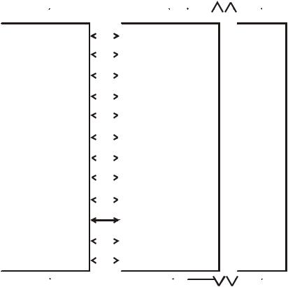
Figure 2.1 shows an example 3 logical responder MXP, which has a capability of 3 X 4 = 12 circuits (C1/1-1/4, C2/1-2/4, C3/1-3/4) and 12 relays (R1/1-1/4 ..... R3/4).
Splitting up the possible 200 addressable devices equally among the 12 circuits results in each circuit being able to service 200/12 = 16 devices, with 8 left over. Thus devices 1-16 are associated with circuit C1/1, devices 17-32 are associated with C1/2, etc, up to C3/4, which not only handles its own 16 points but also the extra 8 device addresses (193-200) otherwise not catered for. Input devices are mapped to circuits, and output devices are usually mapped to relays but may alternatively be mapped to the circuit.
Issue 1.5 |
24 March 2006 |
Page 2-3 |
MX4428 MXP Engineering / Technical Manual |
|
Document: LT0273 |
|||
Responder Loop Design Considerations |
|
|
|
||
|
|
|
|
|
|
|
Number of Logical |
Number of Circuits (Relays) |
Number of Points per circuit |
Total Quantity of Points |
|
|
Responders |
available |
(relay) |
in Last Circuit |
|
|
(NLR) |
(NC = 4 * NLR) |
PC = 200/NC |
|
|
|
|
|
|
|
|
|
1 |
4 |
50 |
50 |
|
|
2 |
8 |
25 |
25 |
|
|
3 |
12 |
16 |
24 |
|
|
4 |
16 |
12 |
20 |
|
|
5 |
20 |
10 |
10 |
|
|
6 |
24 |
8 |
16 |
|
|
7 |
28 |
7 |
11 |
|
|
8 |
32 |
6 |
14 |
|
|
9 |
36 |
5 |
25 |
|
|
10 |
40 |
5 |
5 |
|
|
11 |
44 |
4 |
28 |
|
|
12 |
48 |
4 |
12 |
|
|
13 |
52 |
3 |
47 |
|
|
14 |
56 |
3 |
35 |
|
|
15 |
60 |
3 |
23 |
|
|
16 |
64 |
3 |
11 |
|
|
17 |
68 |
2 |
66 |
|
|
18 |
72 |
2 |
58 |
|
|
19 |
76 |
2 |
50 |
|
|
20 |
80 |
2 |
42 |
|
|
21 |
84 |
2 |
34 |
|
|
22 |
88 |
2 |
26 |
|
|
23 |
92 |
2 |
18 |
|
|
24 |
96 |
2 |
10 |
|
|
25 |
100 |
2 |
2 |
|
|
26 |
104 |
1 |
97 |
|
|
27 |
108 |
1 |
93 |
|
|
28 |
112 |
1 |
89 |
|
|
29 |
116 |
1 |
85 |
|
|
30 |
120 |
1 |
81 |
|
|
31 |
124 |
1 |
77 |
|
|
32 |
128 |
1 |
73 |
|
|
33 |
132 |
1 |
69 |
|
|
34 |
136 |
1 |
65 |
|
|
35 |
140 |
1 |
61 |
|
|
36 |
144 |
1 |
57 |
|
|
37 |
148 |
1 |
53 |
|
|
38 |
152 |
1 |
49 |
|
|
39 |
156 |
1 |
45 |
|
|
40 |
160 |
1 |
41 |
|
|
41 |
164 |
1 |
37 |
|
|
42 |
168 |
1 |
33 |
|
|
43 |
172 |
1 |
29 |
|
|
44 |
176 |
1 |
25 |
|
|
45 |
180 |
1 |
21 |
|
|
46 |
184 |
1 |
17 |
|
|
47 |
188 |
1 |
13 |
|
|
48 |
192 |
1 |
9 |
|
|
49 |
196 |
1 |
5 |
|
|
50 |
200 |
1 |
1 |
|
|
|
|
|
|
|
Table 2-1 Point Allocation For Various Numbers of Logical Responders
Page 2-4 |
24 March 2006 |
Issue 1.5 |
Document: LT0273 |
|
|
|
|
MX4428 MXP Engineering / Technical Manual |
|||||||||||||||
|
|
|
|
|
|
|
|
|
|
|
Responder Loop Design Considerations |
|||||||||
|
|
|
|
ANALOG LOOP |
|
|
|
|
F4000 LOOP |
|
|
|||||||||
|
|
|
|
|
|
|
|
|
|
|
|
|
|
|
|
|||||
|
|
|
|
|
|
|
|
|
|
|
|
|
|
|
|
|
|
|
|
|
|
|
|
|
|
|
MAPPED |
|
|
|
|
|
|
|
|
|
|
|
|
||
|
|
DEVICE 1-16 |
|
|
TO |
C1/1 R1/1 |
|
|
|
|
|
|
|
|
|
|
|
|
||
|
|
|
|
|
|
|
|
|
|
|
|
|
|
|
|
|
|
|||
|
|
|
|
|
|
|
|
|
|
|
|
|
|
|
|
|
|
|
|
|
|
|
DEVICE 17-32 |
|
|
|
|
C1/2 R1/2 |
LOGICAL |
|
|
|
|||||||||
|
|
|
|
|
|
|
|
|
||||||||||||
|
|
|
|
|
|
|
|
|
|
|
|
|||||||||
|
|
|
|
|
|
|
|
|
RESPONDER |
|
|
|
||||||||
|
|
DEVICE 33-48 |
|
|
|
|
C1/3 R1/3 |
|
|
|||||||||||
|
|
|
|
|
|
#1 |
|
|
|
|
|
|
|
|
|
|||||
|
|
|
|
|
|
|
|
|
|
|
|
|
|
|
||||||
|
|
|
|
|
|
|
|
|
|
|
|
|
|
|
|
|
|
|
|
|
|
|
DEVICE 49-64 |
|
|
|
|
C1/4 R1/4 |
|
|
|
|
|
|
|
|
|
|
|
|
|
|
|
|
|
|
|
|
|
|
|
|
|
|
|
|
|
|
|
|||
|
|
|
|
|
|
|
|
|
|
|
|
|
|
|
|
|
|
|
|
|
|
|
DEVICE 65-80 |
|
|
|
|
C2/1 R2/1 |
|
|
|
|
|
|
|
|
|
|
F4000 |
||
|
|
|
|
|
|
|
|
|
|
|
|
|
|
|
|
|||||
|
|
|
|
|
|
|
|
|
|
|
|
|
|
|
|
|
|
|
||
TOTAL OF |
|
DEVICE 81-96 |
|
|
|
|
C2/2 R2/2 |
|
LOGICAL |
|
MASTER |
|||||||||
|
|
|
|
|
|
|
|
|
||||||||||||
200 DEVICES |
|
|
|
|
|
|
|
|
|
RESPONDER |
|
|
|
|||||||
|
|
|
|
|
|
|
|
|
|
|||||||||||
|
|
DEVICE 97-112 |
|
|
|
|
C2/3 R2/3 |
#2 |
|
|
|
|
|
|
|
|
|
|||
|
|
|
|
|
|
|
|
|
|
|
|
|
|
|
||||||
|
|
|
|
|
|
|
|
|
|
|
|
|
|
|
|
|
|
|
|
|
|
|
DEVICE 113-128 |
|
|
|
|
C2/4 R2/4 |
|
|
|
|
|
|
|
|
|
|
|
|
|
|
|
|
|
|
|
|
|
|
|
|
|
|
|
|
|
|
|
|||
|
|
|
|
|
|
|
|
|
|
|
|
|
|
|
|
|
|
|
|
|
|
|
DEVICE 129-144 |
|
|
|
|
C3/1 R3/1 |
LOGICAL |
|
|
|
|||||||||
|
|
|
|
|
|
|
|
|
||||||||||||
|
|
|
|
|
|
|
|
|
|
|
|
|||||||||
|
|
DEVICE 145-160 |
|
|
|
|
C3/2 R3/2 |
|
|
|
||||||||||
|
|
|
|
|
|
|
|
|
RESPONDER |
|
|
|
||||||||
|
|
DEVICE 161-176 |
|
|
|
|
C3/3 R3/3 |
#3 |
|
|
|
|
|
|
|
|
|
|||
|
|
|
|
|
|
|
|
|
|
|
|
|
|
|
|
|
|
|||
|
|
|
|
|
|
|
|
|
|
|
|
|
|
|
|
|
|
|||
|
|
|
|
|
|
|
|
|
|
|
|
|
|
|
|
|
|
|
|
|
|
|
DEVICE 177-200 |
|
|
|
|
C3/4 R3/4 |
|
|
|
|
|
|
|
|
|
|
|
|
|
|
|
|
|
|
|
|
|
|
|
|
|
|
|
|
|
|
|
|||
|
|
|
|
|
|
|
|
|
|
|
|
|
|
|
|
|
|
|
|
|
|
|
|
|
|
|
|
|
|
|
|
|
|
|
|
|
|
|
|
|
|
|
|
|
|
|
ANALOG LOOP |
|
|
|
|
F4000 LOOP |
|
|
||||||||
|
|
|
|
|
|
|
|
|
|
|
|
|
|
|
||||||
3 LOGICAL RESPONDER MXR
Figure 2.1 Device To Circuit Mapping For 3 Logical Responder MXP
2.2.3POINT TO CIRCUIT TO ZONE MAPPING
Taking the 3 logical responder example in the previous sections, assume that of the 16 possible device addresses that belong to C1/1, only 10 of these are in fact used, and that 7 are input devices, and the remaining 3 are output devices. Further, assume that the MX4428 FIP is configured to map C1/1 to ZONE 1.
In this case, an alarm sensed by any of the 7 input devices would put C1/1 into alarm, which in turn would put ZONE 1 into alarm, a condition indicated on the MX4428 Master front panel. However, the MXP also generates what is referred to as an extended event, indicating precisely which of the 7 input devices caused the alarm. This is transmitted to the MX4428 Master where it is presented on the front panel LCD, entered in the history log and printed on the logging printer (if programmed).
If, for instance, in this example it was input device 6 that caused the ALARM then the
extended event would take the form .....
"P1/6 ALARM" where .....
..... P = POINT
1 = BASE ADDRESS OF RESPONDER
6 = DEVICE NUMBER
If the Point Text expansion option is fitted at the MX4428 Master, the event will be associated with a text description of the point.
Issue 1.5 |
24 March 2006 |
Page 2-5 |

MX4428 MXP Engineering / Technical Manual |
Document: LT0273 |
Responder Loop Design Considerations |
|
So far only input devices have been considered. To continue our example for output devices, if the MX4428 Master generated an output command, via output logic, to turn on R1/1, then the MXP would activate all output devices associated with that relay, that is, in this case, all 3.
2.3 IMPLICATIONS TO SYSTEM DESIGN
The System Designer should be aware of the following MX4428 characteristics before
proceeding with the design .....
(i)While the MX4428 with MXP capability can support up to 16 x 200 (3,200) points (i.e. addressable devices), the Master unit has a maximum of 528 zones with which to indicate the status of the system.
The 528 zones may be used to display the status of either an "alarm zone", representing the status of a particular sub-section of the area to be monitored, or an "ancillary control zone" (ACZ), representing the status of an output controlled by the MX4428 system.
The Point Text expansion option can be used to extend this capability. Refer to the F4000 Point Text Installation and Operation Manual (LT0228) for further information.
(ii)FIP zone indicators are controlled according to the zone’s status, which is generated from the mapped circuit status. That is, the 4 circuits monitored by each of the 127 logical responders can control a maximum of 4 x 127 = 508 unique zones.
The point handling capability of an MX4428 system requiring individual LED indicators per monitored point is therefore reduced to 508.
Therefore, the more individual LED indications that the FIP must show for each MXP the more logical responders that MXP must represent.
Every additional 4 zones that must be indicated for the addressable devices on an MXP incurs a cost of 1 additional logical responder (i.e. MX4428 responder loop address).
(iii)For the same reasons as given in (ii) above, the more individually controllable output devices the MXP must drive and control from logic, the more logical responders the MXP must represent.
Page 2-6 |
24 March 2006 |
Issue 1.5 |

Document: LT0273 |
MX4428 MXP Engineering / Technical Manual |
|
Device Information and Programming |
CHAPTER 3 DEVICE INFORMATION AND PROGRAMMING
Issue 1.5 |
24 March 2006 |
Page 3-1 |

MX4428 MXP Engineering / Technical Manual |
Document: LT0273 |
|
Device Information and Programming |
|
|
|
|
|
3.1 |
DEVICE TYPES |
|
The MXP can communicate with a mix of up to 200 addressable devices, within limits defined by loop size.
3.1.1MX DEVICES
MX devices fall into three basic types:
(a) |
Sensors |
- |
Detectors (814PH, 814CH, 814I, 814H, VLC800) |
(b) |
Ancillaries |
- |
Input (Monitor) (MIM800, MIM801, CIM800, DIM800) |
|
|
- |
MCP (CP820, FP0838, FP0839) |
|
|
- |
Output (Control) (RIM800, SNM800, LPS800) |
(c) |
Bases |
- |
Standard Base (MUB, 5B) |
|
|
- |
Short Circuit Isolator (5BI) |
|
|
- |
Relay Base (814RB) |
|
|
- |
Sounder Base (814SB, MkII Sounder Base) |
In addition non-addressable smoke, thermal or flame detectors may be connected to the MXP loop by means of the DIM800 Detector Input Module.
Code |
Description |
Input / |
Remote |
|
|
|
|
Output |
LED |
814PH |
Photoelectric Smoke + Heat Detector |
I/O |
Y |
|
814CH |
Carbon Monoxide + Heat Detector |
I/O |
Y |
|
814I |
Ionisation Smoke Detector |
I/O |
Y |
|
814H |
Heat Detector |
I/O |
Y |
|
VLC800 |
Vesda Aspirating smoke detector |
I/O |
Y |
|
MIM800 |
Mini Input Module |
Input |
|
|
MIM801 |
Mini Input Module normally closed |
Input |
|
|
|
interrupt (FP0837) |
|
|
|
CP820 |
Manual Call Point |
Input |
|
|
FP0838 |
NZ Manual Call Point |
Input |
|
|
FP0839 |
|
|
|
|
CIM800 |
Contact Input Module |
Input |
|
|
DIM800 |
Detector Input Module |
Input |
|
|
RIM800 |
Relay Interface Module (unsupervised |
Output |
|
|
|
load wiring) |
|
|
|
SNM800 |
Sounder Notification Module (relay |
Output |
|
|
|
output with supervised load wiring) |
|
|
|
LPS800 |
Loop Powered Sounder |
Output |
|
|
The devices above are addressed by the |
|
|
||
801AP |
Service Tool |
|
|
|
or by command from the diagnostics terminal of an MXP.
Page 3-2 |
24 March 2006 |
Issue 1.5 |
Document: LT0273 |
MX4428 MXP Engineering / Technical Manual |
|
Device Information and Programming |
The standard base for use with the 814 detectors is:
MUB |
Minerva Universal Base (4”) |
5B |
Minerva Universal Base (5”) |
The following special purpose bases may also be used.
5BI |
Isolator Base |
814RB |
Relay Base |
814SB |
Sounder Base |
MkII Sounder Base |
Sounder Base |
(802SB, 812SB, 901SB, |
|
and 912SB) |
|
The 814RB and 814SB may be plugged into an MUB, 5B or a 5BI, or mounted directly on a wall / ceiling.
Note that none of the bases are addressable devices. The functional bases (814RB, 814SB, and MkII Sounder Base) are controlled by the MXP via the detector which is plugged into them.
The devices above marked as “Input/Output” are always inputs, but may also be used as outputs via the Remote Indicator output and the signal to the 814RB, 814SB, and MkII Sounder Base functional bases. The output functionality is programmable and not necessarily related to the input status.
The devices which have a remote LED output may drive a Tyco E500Mk2 remote LED. The functionality of this LED is programmable and it does not necessarily follow the local LED.
A brief description of the capabilities of each device follows:
a)814I Analogue Ionisation Smoke Detector
This unit uses an ionisation chamber (with a small radioactive source) to detect airborne particles of combustion products.
b)814H Analogue Heat Detector
This detector incorporates a temperature sensor. The temperature sensor processing may be programmed as Type A (rate of rise plus fixed temperature = 63°C), Type B (fixed temperature only = 63°C), Type C (rate of rise plus fixed temperature = 93°C), or Type D (fixed temperature only = 93°C). Type A, B, C or D operation is programmable at the MX4428 panel.
c)814PH Analogue Photoelectric Smoke Detector + Heat Detector
This unit uses light scattering to detect airborne particles of combustion products, and in addition incorporates a temperature sensor. The heat function may be programmed in the same way as for the 814H detector.
d)814P Analogue Photoelectric Smoke Detector
This unit uses light scattering to detect airborne particles of combustion products.
Issue 1.5 |
24 March 2006 |
Page 3-3 |
MX4428 MXP Engineering / Technical Manual |
Document: LT0273 |
Device Information and Programming |
|
e)814CH Analogue CO (Carbon monoxide) Detector + Heat Detector
This unit uses a special sensor to detect carbon monoxide, and in addition incorporates a temperature sensor. The heat function may be programmed in the same way as for the 814H detector.
f)Mini Input Module MIM800
This unit has a single input for monitoring clean contacts (e.g. MCPs, flow switches conventional detectors with hard contact outputs, relay contacts, switches). As well as monitoring the state of the contacts the MIM800 can supervise the wiring for open circuit fault and (optionally) short circuit fault.
g)Mini Input Module MIM801
This unit has a single input for monitoring clean contacts (e.g. MCPs, flow switches, conventional detectors with hard contact outputs, relay contacts, switches). As well as monitoring the state of the contacts the MIM801 can supervise the wiring for short circuit fault and (optionally) open circuit fault. The MIM801 is very similar to the MIM800, however it is optimised for normally closed applications and can generate an interrupt on an open circuit. (Interrupt is only used when a fast response is required.) (The MIM800 and CIM800 can also generate interrupts, but only in response to closing contacts.)
h)Contact Input Module CIM800
This unit has two separate inputs for monitoring switch or relay contacts (e.g. MCPs, flow switches, conventional detectors with hard contact outputs, relay contacts, switches). As well as monitoring the state of the contacts the CIM800 can supervise the wiring for open circuit fault and (optionally) short circuit fault. Although there are two separate inputs, both belong to the same point. Either input in alarm will put the point into alarm, and either input in fault will put the point into fault. Unused inputs must be terminated with a 200Ω resistor.
i)Detector Input Module DIM800
This unit has two separate inputs for monitoring conventional detectors. As well as monitoring the state of the detectors they can supervise the wiring for open circuit faults. Although there are two separate inputs, both belong to the same point. Either input in alarm will put the point into alarm, and either input in fault will put the point into fault. An external power supply is required. The voltage requirements for some conventional detector types are very specific. (Refer to section 3.20).
j)Australian Call Point Module CP820
This unit consists of a MIM800 complete with a call point switch and break-glass housing.
k)New Zealand Call Point Module FP0838, FP0839
This unit consists of a MIM801 complete with a call point switch and break-glass housing. FP0838 is flush mounting while FP0839 is surface mounting.
l)Relay Interface Module RIM800
This unit has voltage free changeover relay contacts rated at 2A 30Vdc for external loads. No supervision of load wiring is provided. However the relay position is supervised and a “relay checkback fail” fault will be generated if it does not operate.
Page 3-4 |
24 March 2006 |
Issue 1.5 |
Document: LT0273 |
MX4428 MXP Engineering / Technical Manual |
|
Device Information and Programming |
m)Sounder Notification Module SNM800
This unit has a relay rated at 2A 30Vdc for switching external loads. Supervision of load wiring and the load supply is provided. The relay position is supervised and a “relay checkback” fault will be generated if it does not operate.
n)Short Circuit Isolator 5BI
This detector base is designed for isolating short circuited sections of the analog loop. For instance it can be used where the loop wiring crosses zone boundaries and it will prevent a short circuit from affecting more than one zone. As well as housing a detector it can be used with no detector inserted.
o)Sounder Base 814SB and MkII Sounder Base
These detector bases are designed as low cost warning devices. The MkII Sounder Base is a newer version of the 814SB. Some variants are loop powered while others are powered by an external supply. The sounder is controlled by the detector which is plugged into the base, but the operation of the sounder can be quite separate from the operation of the detector.
The 814SB can be setup to generate a number of tones (none of which are AS2220 or ISO8201 compliant), and three sound levels are selectable.
The MkII Sounder Base models can be setup to generate a number of tones including AS2220 and ISO8201 compliant evacuation tones, and on some models the sound level is continuously adjustable. Currently none of the MkII Sounder Base models are SSL listed.
Note that the current taken by a loop powered sounder base is very much higher than any of the other loop devices (except the LPS800), and the number of sounder bases on a loop is limited by the available current.
p)Relay Base 814RB
This detector base is designed for a low cost output device. It is controlled by the detector which is plugged into it, but the operation of the relay can be quite separate from the operation of the detector. A voltage two pole changeover relay is provided, rated at 1A 30V dc.
q)Loop Powered Sounder LPS800
This device is similar to the SNM800, in that it drives one or more external sounders, however the sounder power comes from the loop rather than an external power supply. The available output current is much lower than that of a SNM800, and as all this current comes from the loop, the number of LPS800s and their load is limited by the available loop current.
r)Vesda VLC800
The Vision Systems VLC800-MX VESDA Laser COMPACT is an aspirating smoke detector. It samples the smoke from air which is extracted via piping from a large area of a building. The sensitivity is adjustable over a wide range at the VLC800 by PC software programme. The VLC800 requires a 24V power supply.
A summary of the electrical specifications of the various devices is shown in Table 3-1.
Issue 1.5 |
24 March 2006 |
Page 3-5 |
MX4428 MXP Engineering / Technical Manual |
Document: LT0273 |
Device Information and Programming |
|
All loop devices are rated at a loop voltage of 20Vdc - 40Vdc and a signalling voltage of 2V p-p – 6V p-p. Alarm Currents specified do not include remote indicators. Add 7mA for each remote indicator.
DEVICE |
FUNCTION |
Comments |
|||
|
|
|
|
|
|
814I |
|
Ionisation Smoke Detector |
Requires base |
||
814H |
|
Heat Detector |
Requires base |
||
814PH |
Photo Smoke + Heat |
Requires base |
|||
Detector |
|
||||
|
|
|
|
||
814P |
|
Photo Smoke Detector |
Requires base |
||
814CH |
CO + Heat Detector |
Requires base |
|||
MIM800 |
Mini Input Module |
EOL 200Ω |
|||
|
Alarm R (if used) 100Ω |
||||
|
|
|
|
Max Wiring R 10Ω |
|
|
|
|
Mini Input Module |
N/O mode - as MIM800 |
|
MIM801 |
(normally closed interrupt) |
N/C - |
|||
|
EOL 200Ω |
||||
|
|
|
|
||
|
|
|
|
Max wiring R 50Ω |
|
CIM800 |
Contact Input Module |
EOL 200Ω |
|||
|
Alarm R (if used) 100Ω |
||||
|
|
|
|
Max Wiring R 10Ω |
|
DIM800 |
(Conventional) Detector |
EOL 4k7 |
|||
Interface Monitor |
Requires separate supply. |
||||
|
|
|
|||
CP820 |
Call Point |
|
|||
FP0838, FP0839 |
NZ Call Point |
|
|||
RIM800 |
Relay Interface Module |
2A 30Vdc |
|||
|
|
|
Sounder Notification |
2A 30Vdc. |
|
SNM800 |
Module (Supervised relay |
Requires external supply. |
|||
|
|
|
output) |
|
|
LPS800 |
Loop Powered Sounder |
Provides 24V at up to 75mA |
|||
Module |
|
||||
|
|
|
|
||
MUB |
|
Standard Base |
|
||
5BI |
|
Isolator Base |
|
||
814SB |
Loop Powered Sounder |
Selectable tone (not AS2220 or ISO8201) |
|||
Base |
Adjustable sound level |
||||
|
|
|
|||
|
|
|
Loop Powered Sounder |
Selectable tone (Including AS2220 and ISO |
|
|
|
802SB |
Base |
8201 Evacuation tone) |
|
|
|
|
|
Adjustable sound level |
|
|
|
812SB |
Loop Powered Sounder |
Selectable tone (Including AS2220 and ISO |
|
MkII |
|
Base |
8201 Evacuation tone) |
||
|
|
||||
|
|
Externally Powered |
Selectable tone (Including AS2220 and ISO |
||
Sounder |
|
|
|||
|
|
Sounder Base |
8201 Evacuation tone) |
||
Bases |
|
901SB |
|||
|
|
Adjustable Sound Level. |
|||
|
|
|
|
||
|
|
|
|
Requires external 24V |
|
|
|
|
Externally Powered |
Selectable tone (Including AS2220 and ISO |
|
|
|
912SB |
Sounder Base |
8201 Evacuation tone) |
|
|
|
|
|
Requires external 24V |
|
814RB |
Relay Base |
1A 30Vdc |
|||
|
2 pole changeover |
||||
|
|
|
|
||
VLC800 |
Vesda aspirating smoke |
Requires external supply. Requires PC to |
|||
detector |
set up. |
||||
|
|
|
|||
|
|
|
|
|
|
Table 3-1 Compatible Device Summary
The MXP will allow some alternative devices to be used without generating a fault, where the inserted device can provide all the features of the configured device. This includes an 814PH or 814CH used where an 814H was programmed, a CIM800 used where a MIM800 was programmed, and an 814PH used where an 814P was programmed.
Page 3-6 |
24 March 2006 |
Issue 1.5 |

Document: LT0273 |
MX4428 MXP Engineering / Technical Manual |
|
Device Information and Programming |
|
|
3.2 |
DEVICE HANDLING CAPABILITY |
3.2.1OVERVIEW
The parameters which determine the maximum number of each device type that can be put on a loop are as follows. The column “MAX NO. DEVICES” assumes that all devices are of the same type. If this is not the case, it is necessary to perform the calculations described below.
DEVICE |
MAX NO. |
Quiescent |
Alarm |
AC Units |
IB Units |
|
DEVICES |
Current |
Current |
(max 250 |
(max 100 IB |
|
|
|
|
total) |
units between |
|
|
|
|
|
Isolator Bases) |
814I |
200 |
330uA |
3.0mA |
1 |
1.4 |
814H |
200 |
250uA |
3.0mA |
1 |
1 |
814PH |
200 |
275uA |
3.0mA |
1 |
1.2 |
814P |
200 |
275uA |
3.0mA |
1 |
1.2 |
814CH |
200 |
275uA |
3.0mA |
1 |
1 |
MIM800 |
200 |
275uA |
2.8mA (with LED) |
1 |
1.5 |
|
|
|
275uA (no LED) |
|
|
MIM801 |
200 |
275uA |
2.8mA (with LED) |
1 |
1.5 |
|
|
|
275uA (no LED) |
|
|
CIM800 |
200 |
275uA |
2.8mA |
1 |
1 |
DIM800 |
200 |
100uA |
100uA (Loop) |
1 |
1 |
|
|
(Loop) |
|
|
|
CP820 |
200 |
275uA |
2.8mA |
1 |
1.5 |
RIM800 |
200 |
285uA |
2.8mA (with LED) |
1 |
5 |
|
|
|
285uA (no LED) |
|
|
SNM800 |
200 |
450uA |
3.0mA (with LED) |
1 |
5 |
|
|
|
450uA (no LED) |
|
|
LPS800 |
33 or less, |
450uA |
Load current + |
1.5 |
1 |
|
depends on |
|
4mA, with |
|
|
|
load |
|
minimum of 12mA |
|
|
5BI |
N/A |
80uA |
|
0.2 |
N/A |
814SB |
40(Quiet) |
400uA |
9mA(Quiet) |
2.4 |
2.5 |
|
30(Medium) |
|
12mA(Medium) |
|
|
|
24(Loud) |
|
15mA(Loud) |
|
|
802SB* |
200(Quiet) |
200uA |
1.2mA (Quiet) |
0.5 |
2.5 |
|
50 (Loud) |
|
6.8mA (Loud) |
|
|
812SB* |
18 |
200uA |
21mA |
0.5 |
2.5 |
901SB* |
200 |
200uA |
200uA (Loop) |
0.5 |
2.5 |
912SB* |
200 |
200uA |
200uA( Loop) |
0.5 |
2.5 |
814RB |
200 |
50uA |
100uA |
0.3 |
1.6 |
VLC800 |
125 |
300uA |
300uA (no LED) |
2 |
1 |
|
|
|
2.8mA (with LED) |
|
|
|
|
|
|
|
|
*Models of MkII Sounder Base
Table 3-2 Device Quantities and Loading
The particular combination of device types, external loads, cable length and type may limit the total number of devices. This is calculated in the following sections.
There are two types of load which must be considered - DC and AC. Also if isolator bases are used, the loading between each isolator base must be considered.
Issue 1.5 |
24 March 2006 |
Page 3-7 |
MX4428 MXP Engineering / Technical Manual |
Document: LT0273 |
Device Information and Programming |
|
It is recommended that the PC program F4000CAL is used for conducting the loop loading calculations. However note that it does not include the isolator base loading, this must be done manually.
3.2.2DC LOAD
The total current available from the MX Loop terminals on the MXP is 400mA DC.
This must supply operating current to all addressable devices an the loop. This not only includes the quiescent current required to power the device electronics, but also the additional current drawn by devices in the ALARM state or by associated ALARM LEDs and other loop powered outputs.
The sum of currents for all devices connected to the loop is calculated using the “alarm current” values shown in Table 3-2. Note –
1)The MXP limits the number of Alarm LEDs turned on at any one time to 5 (programmable at MX4428).
2)Remote LEDs must be allowed for at 7mA each. Remote LEDs programmed to follow the detector LED will be limited by the number of alarm LEDs. However remote LEDs programmed to operate on “Circuit Alarm” or “Relay” will not be limited in any way.
3)LEDs on relay output devices (SNM800, RIM800, LPS800) will operate when the relay is activated, if the MXP is configured at the MX4428 to flash the LED on Poll “Global Blink Mode”.
4)The 814RB, RIM800 and SNM800 relay load current must not be supplied from the analogue loop.
The sum of all currents must not exceed 400mA.
Furthermore, the voltage drop in the cable must not exceed 16.0V, regardless of which end of the loop the cable is driven from. This is in order to ensure that with the minimum 36V voltage available from the MX Loop terminals on the MXP, the minimum voltage at any device will be at least 20V.
If you have any LPS800 devices on the loop, you may need to design for a higher minimum loop voltage and a lower voltage drop. Refer to section 3.23.2.
3.2.3AC LOADING
Calculate the total of the “AC Units” shown in Table 3-2. The total must not exceed 250.
Also ensure that the cable length does not exceed the values in Table 3-3.
Cable type |
Cable length |
MICC 2L1.5, 2L2.5, 1H1.5, 2H2.5 |
1.8 km* |
Steel Wire Armour (SWA) |
1.8 km* |
Fire resistant ‘foil and drain wire’, e.g. |
2 km |
Radox FR3013, FP200, Lifeline, Firetuff |
|
BS6883 marine cable |
2 km |
Table 3-3 Maximum Cable Lengths
* Up to 2km of these cable types may be used on condition that the maximum AC loading is restricted to less than 220 AC units per loop.
Page 3-8 |
24 March 2006 |
Issue 1.5 |
Document: LT0273 |
MX4428 MXP Engineering / Technical Manual |
|
Device Information and Programming |
3.2.4ISOLATOR BASE LOADING
If isolator bases are being used, calculate the sum of the “IB Units” from Table 3-2 for each section of cable between isolator bases (or between the last isolator base and the end of a cable spur). Include only one of the detectors at the ends of the section. The sum for any section must not exceed 100.
See also section 4.1.3 for details of AS1670 requirements and section 4.1.4 for details of NZS4512 requirements.
3.2.5EXAMPLE
Consider an MXP monitoring 200 * 814PH detectors with 10 814SB Sounder Bases set to High, on a 1300 metre long loop, using 1.5mm2 wire. The cable is divided (with 9 Isolator Bases) into 10 segments with 1 Sounder Base and 20 detectors on each segment.
(i)Calculate DC Load
IA = 195 x 275uA |
(No. of detectors in NORMAL) |
+ 5 x 3.0mA |
(No. of detectors with Alarm LEDs turned on, assume limited to |
|
5 max by MXP) |
+10 x 15mA (Number of 814SB Sounder Bases)
+9 x 80uA (Number of Isolator Bases)
(Ref Table 3-2. Note 1mA = 1000uA) = 220mA which is well under 400mA
For the voltage drop calculation, assume the worst case in the first instance, i.e. that all devices are at the far end of 1300 metres. The loop resistance of 1.5mm2 wire is 25Ω per 1000m and the isolator base resistance is 0.25Ω.
Total R = 25Ω x 1.3 + 9 x 0.25Ω = 34.75Ω.
Voltage drop = 34.75 x 0.220 = 7.7V, which is well under the maximum allowable of 16V.
(ii)Calculate AC Load
|
AC Units |
= |
200 x 1 (detectors) |
||
|
|
|
+ 10 x 2.4 |
(Sounder Bases) |
|
|
|
|
+ 10 x 0.1 |
(Isolator Bases) |
|
|
|
= |
225 which is less than the maximum allowable of 250. |
||
|
Cable length is well under the limits specified in Table 3-3. |
||||
(iii) |
Calculate IB Load |
|
|
|
|
|
IB Units for each section |
= 20 * 1.2 (814PH) + 1 * 2.5 (814SB) |
|||
|
|
|
|
= |
26.5 which is less than 100. |
As all parameters are within the specified limits, the design is satisfactory.
Issue 1.5 |
24 March 2006 |
Page 3-9 |

MX4428 MXP Engineering / Technical Manual |
Document: LT0273 |
|
Device Information and Programming |
|
|
|
|
|
3.3 |
OUTPUT CONTROL |
|
The following “outputs” are available on the Analogue loop –
•Output modules – RIM800, SNM800, and LPS800
•Functional Base outputs of detectors (controlling 814SB, MkII Sounder Base or 814RB)
•Remote LED output of detectors.
Each of these is programmable at the MX4428 for which of 3 sources controls the output.
In all cases the outputs are turned off if the point is isolated.
The 3 selectable sources are as follows –
1. Relay output
The output is controlled by the state of the corresponding relay output as sent to the responder. The relay output state can be controlled directly with a logic equation, be controlled by the state of the ACZ that the relay is mapped to (this also allows supervision fault states on the SNM800 and LPS800 output to be indicated), or be controlled by the test state of the flow switch zone it is mapped to.
The functional bases and remote LED outputs for detectors mapped to circuit X of logical responder R will be controlled by the state of relay X of logical responder R, i.e. the relay with the same number as the detector circuit.
2. Circuit alarm
The output will turn on when the corresponding circuit goes into alarm. If the circuit maps to a latching zone then the output will turn off when the zone alarm is reset. If the circuit does not map to a latching zone the output will turn off when the circuit goes out of alarm. The circuit alarm state is determined by the MXP and so can’t include other responder circuits, nor the state of the zone(s) the circuit maps to. (Use “relay output” if these are needed.)
The functional bases and remote LED outputs for detectors will be controlled by the circuit the detector is mapped to. Output modules mapped to relay X of logical responder R will be controlled by circuit X of logical responder R, i.e. the circuit with the same number as the relay.
WARNING - the output will not be disabled by zone isolate.
3. Point alarm
The output will turn on when that point goes into alarm. If the point maps to a latching zone then the output will stay on until the zone alarm is reset. If the point does not map to a latching zone the output will turn off when the point goes out of alarm.
This option is not available on output modules (RIM800, SNM800, and LPS800).
WARNING - the output will not be disabled by zone isolate.
Page 3-10 |
24 March 2006 |
Issue 1.5 |
Document: LT0273 |
MX4428 MXP Engineering / Technical Manual |
|
Device Information and Programming |
3.3.1PROGRAMMING
The programming of the output functions is done by setting the “mode” value for the RIM800, SNM800, and 814I, and by one of the 7 device parameters for the 814H, 814PH, and 814CH. The LPS800 is programmed as an SNM800.
For example the following are the settings for the 814I.
Mode |
Functional Base Control |
Remote LED Control |
0 |
Circuit Alarm |
Circuit Alarm |
1 |
Circuit Alarm |
Relay |
2 |
Circuit Alarm |
Point Alarm |
4 |
Relay |
Circuit Alarm |
5 |
Relay |
Relay |
6 |
Relay |
Point Alarm |
8 |
Point Alarm |
Circuit Alarm |
9 |
Point Alarm |
Relay |
10 |
Point Alarm |
Point Alarm |
The value must be chosen from the above table to give the desired settings for controlling the functional base and the remote LED.
For the 814PH and 814CH, programming of the “enhancement multiplier” is included in the same parameter. The desired enhancement multiplier must be multiplied by 16 and the result added to the above numbers. The tables in the sections for these detectors (3.9.3 and 3.10.3) include the result when the default enhancement multiplier is used.
For the 814H detector and for an 814PH or 814CH with enhancement disabled, the “enhancement multiplier” is irrelevant and therefore the above numbers may be entered directly if desired. The global defaults for parameter 6 for all these detector types should always include the desired enhancement multiplier * 16.
For the SNM800, other options are also included in the mode. Refer to section 3.22.4 for details.
3.3.2OUTPUT STATE UNDER EXCEPTIONAL CIRCUMSTANCES
All outputs retain their state if the MX4428 stops polling the responder (e.g. processing is stopped), or if the MXP stops polling the devices (e.g. due to a new configuration download from the MX4428). If a detector is removed from a relay or sounder base, the relay or sounder output turns off.
If power to the MXP is lost, loop powered sounder bases turn off. RIM800 and SNM800 outputs, relay bases and possibly externally powered sounder bases usually retain their state until MXP power is restored, then turn off when polling resumes (which may take some minutes if the MXP has been off for some hours and lost its configuration), then revert to ON after a few seconds if this is the correct state.
Issue 1.5 |
24 March 2006 |
Page 3-11 |

MX4428 MXP Engineering / Technical Manual |
Document: LT0273 |
Device Information and Programming |
|
3.4 DETECTOR PARAMETER SETTINGS SUMMARY
The following table gives a summary of the MX4428 default and alternate settings, and approved range, for each detector type.
Detector |
Default |
Alternate |
Range |
Comments |
814PH |
12% |
8% |
8% - 12% |
Enhancement is optional, |
Smoke |
(80 det units) |
(37 det units) |
|
default off. |
814PH |
Medium |
N/A |
Low, Medium, |
Enhancement is optional, |
Smoke |
|
|
High (all |
default off. |
FastLogic |
|
|
approved with |
|
|
|
|
nominal |
|
|
|
|
sensitivity = |
|
|
|
|
8%) |
|
814PH Heat |
63 |
N/A |
60 - 65 |
Type B default. |
component |
|
|
|
Type A is option |
|
|
|
|
Off is option. |
814CH |
38ppm |
66ppm(1) |
23 - 66ppm(1) |
Enhancement is optional, |
CO |
(0.3 MIC X) |
(0.6 MIC X) |
|
default off. |
|
(93 det units) |
(160 det units) |
|
(23ppm = 0.15 MIC X |
|
|
|
|
= 60 det units) |
814CH Heat |
63 |
N/A |
60 - 65 |
Type A default. |
component |
|
|
|
Type B is option |
|
|
|
|
Off is option. |
814I |
0.39 MIC X |
0.22 MIC X |
0.2 - 0.4 (Aus) |
0.59 MIC X =130 det |
|
(66 det units) |
(23 det units) |
0.2 - 0.6 (NZ) |
units |
814H |
63 |
N/A |
60 - 93 (Aus) |
Type A default. Type B |
|
|
|
50 - 80 (NZ) |
option. |
|
|
|
|
Types C/D by changing |
|
|
|
|
temperature to 93. |
VLC800 |
Fixed at 100 |
|
0.005% / m to |
Note that actual |
|
|
|
20% / m |
sensitivity is adjusted by |
|
|
|
|
PC connected to the |
|
|
|
|
VLC800. |
(1) 66ppm is outside the approved range of the 814CH as an ionisation detector. However it is an accepted value as a CO detector.
Prealarm
The Prealarm default and alternate sensitivities will generally be about 70% - 80% of the corresponding alarm level. Note that Prealarm will also be more sensitive to rapidly changing conditions as it does not go through the step limiting filter.
Conversion
Det Units = Detector Units.
Temperatures are already converted by the MXP to degrees C and do not require conversion.
Page 3-12 |
24 March 2006 |
Issue 1.5 |

Document: LT0273 |
MX4428 MXP Engineering / Technical Manual |
|
Device Information and Programming |
Conversion from detector units to displayed values is by imagining a graph with a series of joined straight lines from (0,0) and passing through each of the above defined points (e.g. 814PH 37 det units = 8%) and extrapolated in a continuing straight line past the highest point if necessary.
For the 814PH detector the displayed values bear little resemblance to the static sensitivity of the detector. They are valid only for the tests done in the SSL smoke room.
3.5 |
DEVICE INSTALLATION |
3.5.1PRECAUTIONS
Observe ESD precautions when installing an MXP responder, or connecting any devices to it. Refer to Product Bulletin PBG0025.
3.5.2MOUNTING
Detector Bases
Detectors attach to a circular, plastic base which has holes for screw mounting to a flat surface, and screw terminals for connecting the loop wiring. There are various different bases available. Most of the bases may only be mounted as just described, but the 814SB sounder base and the 814RB relay base may be mounted as just described, or may themselves be plugged into one of the other bases, to interpose between it and the detector.
Modules
The Modules are normally mounted within the enclosure of the equipment to which they connect, or in a cabinet, junction box or switch box. They may be mounted on plastic standoffs (4 x HW0130 required) on a gearplate or cabinet, or to a face plate that mounts on a double flush or surface box. A hole may be required for the on-board LED. A standard plate with a hole for the LED and three holes for the Service Tool is available (Ancillary Cover M520). This fits a plastic surface box K2142.
The MIM800/801 is smaller than the other modules, and is supplied in a plastic housing which has a lug for screw mounting.
3.5.3ADDRESS & LED BLINK PROGRAMMING
Addresses for MX detectors and modules, and options such as LED blink on poll, are most easily set using the MX Service Tool. These are set by placing the detector onto the Service Tool, or connecting the module to the Service Tool with the supplied interface lead, and programming as per the MX Service Tool Instructions. (Be careful not to leave the pins in the module when removing the lead).
For all input devices, including detectors, the LED turns on steady when in alarm. For output devices (RIM800, etc) the LED turns on when the device is activated (if Global Blink Mode is enabled for the MXP). To enable a device’s LED to blink on poll, the MXP must have Global Blink Mode enabled at the MX4428 panel, and the device must have LED Blink enabled.
For a mixed system, i.e. some devices are to blink on poll and some are not, then turn off blink on those devices that are not to blink using the Service Tool, and enable Global Blink Mode at the MX4428 panel for the MXP.
Issue 1.5 |
24 March 2006 |
Page 3-13 |

MX4428 MXP Engineering / Technical Manual |
Document: LT0273 |
|
Device Information and Programming |
|
|
|
|
|
3.6 |
MX4428 PROGRAMMING |
|
In the following sections information is given about the programming of each device in the MX4428. An explanation of the mode and the various parameters is given for each device type, along with the global parameters that affect that device type. It is critical that only the listed mode values are used for each device type, as in many cases the mode value is used to define the actual device type. An incorrect mode value may cause a POINT TYPE MISMATCH to be generated, or it may just render a device not able to work.
In some of the following sections descriptions are given about changing the sensitivity for a detector by altering the specific parameter for that detector. This is correct (it sets the value for just that individual detector), but in many cases it may be better to adjust the global sensitivity for that device type so that all detectors of that type take on the new value. For example, in NZ mode it is recommended that the global heat alarm temperature be set to 57°C for both 814PH and 814CH, rather than setting each specific detector to this value.
Details for NZ mode settings are contained in the F4000 NZ Technical Manual (LT0126).
These details are most relevant when programming the MX4428 from a (dumb) programming terminal. Alternatively you can program with "SmartConfig", which displays and edits functional parameters and takes care of mapping the functional parameters into the appropriate mode and parameter bytes for each device type.
Page 3-14 |
24 March 2006 |
Issue 1.5 |
Loading...