

Page 1
http://www.tyco-reproducts.com
Close
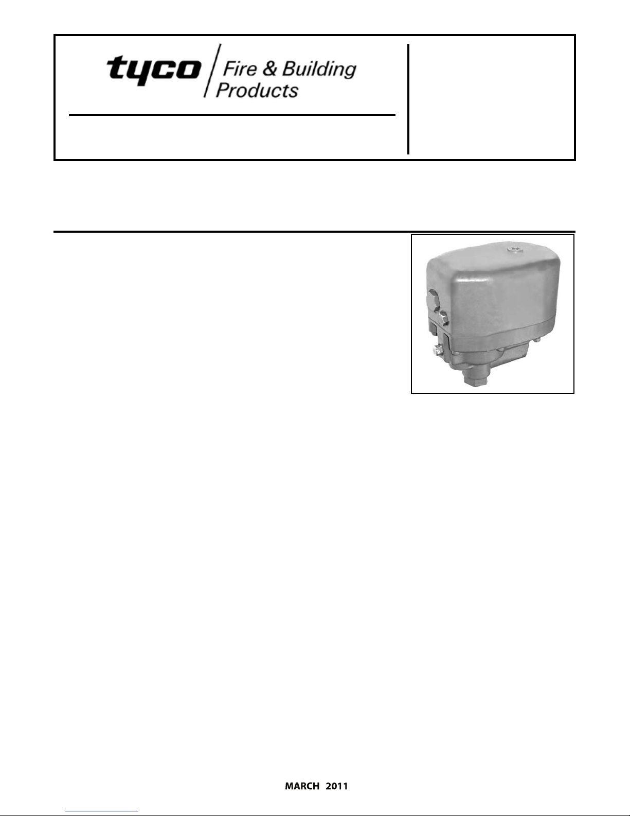
Model ACC‑1 Dry Pipe Valve Accelerator
External Resetting Quick Opening Device
For Dry Pipe Valves
General
Description
The Model ACC‑1 Accelerator is a quick
opening device intended for attachment
Tyco Fire & Building Products, 2‑1/2,
to the
3, 4 or 6” Model DPV‑1 Dry Pipe Valve. The
Model ACC‑1 Accelerator reduces the time
for valve operation following the operation
of one or more automatic sprinklers.
The Model ACC‑1 Accelerator automatical‑
ly adjusts to both small and slow changes
in system pressure, but trips when there is
a rapid and steady drop in pressure (as in
the case of a sprinkler operation). Upon
tripping, the Accelerator transmits system
air pressure to the intermediate chamber of
the Model DPV‑1 Dry Pipe Valve. This neu‑
tralizes the dierential pressure holding the
Model DPV‑1 Dry Pipe Valve closed and per‑
mits it to open.
The Model ACC‑1 Accelerator has a unique,
e ac
positiv
and a ball oat which combine to prevent
water and water borne debris from entering
the more sensitive operating areas of the
acceler
latches immediately upon operation of the
Model ACC‑1 Accelerator without waiting
for a pressure build‑up in the intermediate
chamber of the dry pipe valve. The latching
featur
even while the system is being drained. The
ball oat seals the pilot chamber inlet port
if there is an inadvertent trip of the dry pipe
valve, due for example, to an air compressor
failure combined with a slow loss in system
air pressure due to a leak.
The Model ACC‑1 Dry Pipe Valve Accelerator
is a direct replacement for the Central Mod‑
el B, Gem Model F311, and Star Model S430.
Contact the Technical Services Department
for information concerning the use of the
ACC‑1 for use with dry pipe valves other
than the Model DPV‑1.
tion, internal anti‑ood device
ator. The anti‑ood device seals and
e keeps the anti‑ood device sealed,
WARNING
The Model ACC‑1 Dry Pipe Valve Accelerator
described herein must be installed and main‑
tained in compliance with this document, as
well as with the applicable standards of the
National Fire Protection Association, in addi‑
to
the standards of any other authori‑ties
tion
having jurisdiction. Failure to do so may im‑
pair the integrity of this device.
The owner is responsible for maintaining their
re protection system and devices in proper
operating condition. The installing contrac‑
tor or sprinkler manufacturer should be con‑
tacted relative to any questions.
Technical Data
Approvals
UL and ULC Listed. FM and LPCB Approved.
Maximum Working Water Pressure
17,2 bar (250
Maximum Working Air Pressure
4,8 bar (70
Pressure Decay For Trip
0,07 bar/min (1
Physical Characteristics
Body components constructed of alodine
coated aluminum alloy with austenitic se‑
ries stainless steel internal components.
Seals are EPDM and silicone.
psi)
psi)
psi/min)
Design Data
The connection to the system piping,
Figure 4, must be located so that drain
back water will not ow into the Accel‑
erator piping and it must be located at
a point above the maximum expected
level of the drain back/condensate water.
If the connection is made to the riser, it
must be located at least two feet above
the level of the dry pipe valve. Connec‑
tions to a feed or cross main must be
made either to the side or top of the main.
NOTES
Failure to follow the above instructions can
result in accidental tripping due to closure of
the ball oat.
Quick operation of the Accelerator does not
ensure that the re protection system will
meet the water delivery time requirement of
the authority having jurisdiction (following
opening of the Inspector’s Test Connection).
The sprinkler system designer needs to be
aware that water delivery time is primarily
determined by the conguration and volume
of the piping network, system air pressure
at time of Accelerator trip, and water supply
characteristics.
Page 1 of 10 TFP1112_EN
Page 2
Page 2 of 10 TFP1112_EN
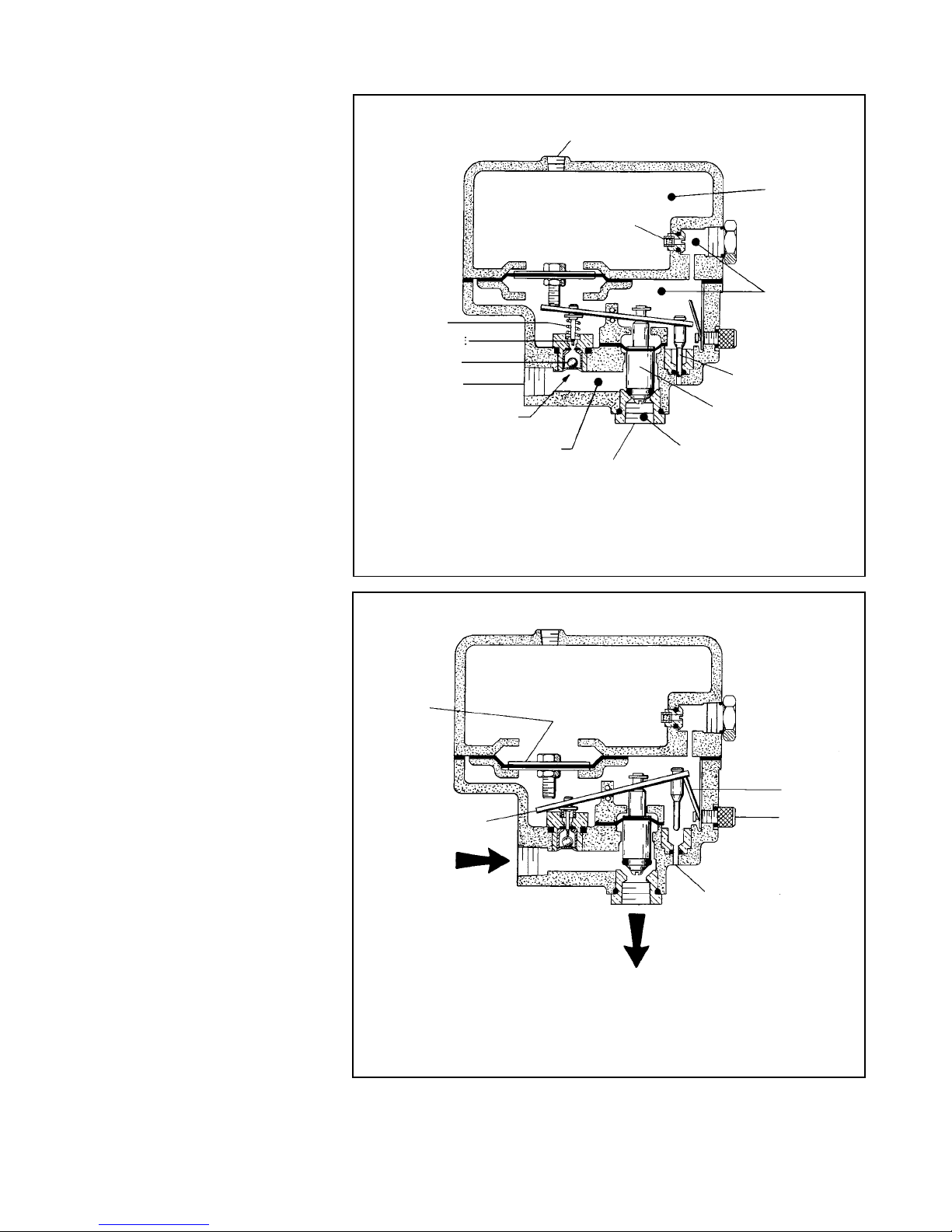
FIGURE 1
MODEL ACC-1 ACCELERATOR IN SET POSITION
FIGURE 2
MODEL ACC-1 ACCELERATOR IN TRIPPED POSITION
TFP1112
Operation
The Inlet Chamber of the Accelerator, Fig‑
ure 1, is pressurized via its connection to
the system (at a point above the maximum
expected level of drain back water). The Pi‑
lot Chamber is, in turn, pressurized through
its inlet port which is formed by the annular
opening around the lower tip of the Anti‑
Flood Valve. As the Pilot Chamber increases
in pressure, the Dierential Chamber is
pressurized through the Restriction.
The Accelerator is in its set position while it
is being pressurized as well as after the In‑
let, Pilot Chamber and Dierential Chamber
pressures have equalized. When in the Set
position, the Outlet Chamber is sealed o
by the Exhaust Valve which is held against
its seat by a combination of the Spring
pushing up against the Lever and the net
downward force exerted by the pressure in
the Pilot Chamber.
Both small and slow changes in system pres‑
sure are accommodated by ow through
the Restriction. When, however, there is a
rapid and steady drop in system (i.e., Inlet
and Pilot Chamber) pressure, the pressure
in the Dierential Chamber reduces at a
substantially lower rate. This condition cre‑
ates a net downward force on the Plunger
which rotates the Lever. As the Lever is ro‑
tated, Figure 2, the Relief Valve is raised out
of the Relief Port and the Anti‑Flood Valve is
depressed downward into the Pilot Cham‑
ber Inlet Port, venting the Pilot Chamber.
The system pressure in the Inlet Chamber
then forces (raises) the Exhaust Valve o its
seat. This continues the rotation of the Le‑
ver into the tripped (latched) position, Fig‑
ure 2. As the Exhaust Valve is raised o its
seat, system pressure is transmitted to the
intermediate chamber of the dry pipe valve
which neutralizes the dierential pressure
holding the valve closed.
Following the dry pipe valve trip, major wa‑
ter borne debris is prevented from entering
the Accelerator (via the connection to the
system piping) by the Strainer located at its
Inlet. Water and any ne water borne debris
such as silt is prevented from entering the
Pilot Chamber by virtue of the Anti‑Flood
Valve having sealed o its inlet port. The
Check Valve located downstream of the Ac‑
celerator Outlet prevents any water borne
debris from entering the Accelerator via the
connection to the intermediate chamber of
the dry pipe valve.
After the accelerator/dry pipe valve has
tripped and the sprinkler system has been
drained, the piping from the system to the
Accelerator must also be drained and the
SPRING
ANTI‑FLOOD VALVE
BALL FLOAT
1/2” NPT INLET
PLUNGER
FROM SYSTEM
PIPING
PILOT CHAMBER
INLET PORT
INLET CHAMBER
1/4” NPT GAUGE
CONNECTION
RESTRICTION
1/2” NPT OUTLET
RELIEF VALVE
EXHAUST VALVE
OUTLET CHAMBER
FIGURE 1
MODEL ACC‑1 ACCELERATOR IN SET POSITION
LEVER
RELIEF PORT
TO DRY PIPE VALVE
INTERMEDIATE
CHAMBER
FIGURE 2
MODEL ACC‑1 ACCELERATOR IN TRIPPED POSITION
DIFFERENTIAL
CHAMBER
PILOT CHAMBER
LATCH
RESET KNOB
Page 3
TFP1112_EN Page 3 of 10
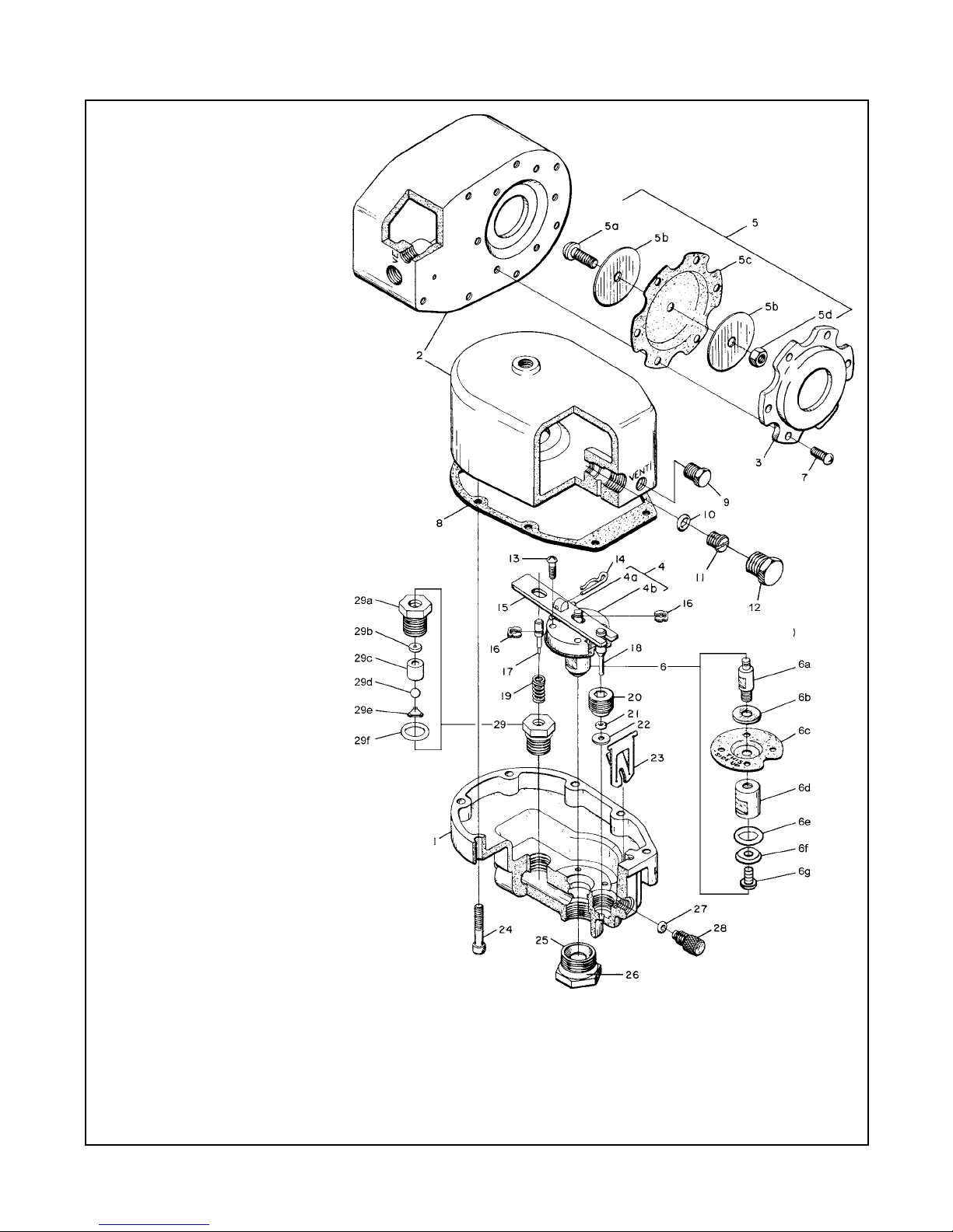
FIGURE 3
MODEL ACC-1 ACCELERATOR ASSEMBLY
NO. DESCRIPTION QTY. P/N
1 Base 1 NR
2 Cover 1 NR
3 Upper Diaphragm
Plate 1 See (c)
4 Pivot Plate
Assembly 1 See (b)
a Spirol Pin 1
b Pivot Plate 1
5 Plunger 1 See (a)
a Pan Hd. Machine
Screw 1
b Upper Diaphragm
Retaining Ring 2
c Upper Diaphragm 1
d Jam Nut 1
6 Exhaust Valve 1 See (a)
a Upper Plug 1
b Washer 1
c Lower Diaphragm 1
d Lower Plug 1
e O-Ring* 1
f O-Ring Retainer 1
g Exhaust Valve Screw 1
7 Rd. Head Machine
Screw,
1/4"-20 UNC x 5/8" 6 See (c)
8 Cover Gasket 1 See (a)
9 Vent Plu g 1 See (c)
10 O-Ring* 1 See (a)
11 Restriction 1 See (a)
12 Restriction Access
Plug 1 See (c)
13 Pan Hd. Machine
Screw,
No. 10-32 UNF x 5/8" 4 See (b)
14 Cotter Pin 1 See (b)
15 Lever 1 See (b)
16 Retaining Ring 1 See (b)
17 Anti-Flood Valve 1 See (b)
18 Relief Valve 1 See (b)
19 Spring 1 See (b)
20 Relief Valve Seat 1 See (b)
21 O-Ring* 1 See (b)
22 Seal Washer 1 See (b)
23 Latch 1 See (a)
24 Fillerster Hd.
Machine Screw,
1/4"-20 UNC x 1-1/2" 8 See (c)
25 Plug Seat 1 See (c)
26 O-Ring* 1 See (c)
27 O-Ring* 1 See (a)
28 Reset Knob 1 See (c)
29 Anti-Flood Seat
Assembly
w/Ball Float 1 See (b)
a Insert 1
b Seal 1
c Guide 1
d Ball 1
e Clip 1
f O-Ring* 1
* Requires thin film of
FS3452 Fluorosilicone Grease
(a) Repair Parts Kit (a)
Includes Items 5, 6, 8,
10, 11, 23, 27 &
1.5 grams of FS3452 92-311-1-116
(b) Replacement Parts
Kit (b) Includ es Items
4, 13-22, 29 &
1.5 grams of FS3452 92-311-1-117
(c) Replacement Parts
Kit (c) Includes Item s
3, 7, 9, 12, 24-26, 28,
& 1.5 grams of FS3452 92-311-1-118
NR: Not Replaceable
Page 3 of 8
TFP1112
NO. DESCRIPTION QTY P/N
1 Base 1 NR
2 Cover 1 NR
3 Upper Diaphragm Plate 1 See (c)
4 Pivot Plate Assembly 1 See (b)
a Spirol Pin 1
b Pivot Plate 1
5 Plunger 1 See (a)
a Pan Hd. Machine Screw 1
Upper Diaphragm Retaining
b
Ring
2
c Upper Diaphragm 1
d Jam Nut 1
6 Exhaust Valve 1 See (a)
a Upper Plug 1
b Washer 1
c Lower Diaphragm 1
d Lower Plug 1
e O‑Ring* 1
f O‑Ring Retainer 1
g Exhaust Valve Screw 1
7 Rd. Head Machine Screw,
1/4”’‑20 UNC x 5/8”
6 See (c)
8 Cover Gasket 1 See (a)
9 Vent Plug 1 See (c)
10 O‑Ring* 1 See (a)
11 Restriction 1 See (a)
12 Restriction Access Plug 1 See (c)
13 Pan Hd. Machine Screw, No.
10‑32 UNF X 5/8”
4 See (b)
14 Cotter Pin 1 See (b)
15 Lever 1 See (b)
16 Retaining Ring 1 See (b)
17 Anti‑Flood Valve 1 See (b)
18 Relief Valve 1 See (b)
19 Spring 1 See (b)
20 Relief Valve Seat 1 See (b)
21 O‑Ring* 1 See (b)
22 Seal Washer 1 See (b)
23 Latch 1 See (a)
24 Fillerster Hd. Machine Screw,
1/4”‑20 UNC x 1‑1/2”
8 See (c)
25 Plug Seat 1 See (c)
26 O‑Ring* 1 See (c)
27 O‑Ring* 1 See (a)
28 Reset Knob 1 See (c)
29 Anti‑Flood Seat Assembly
w/Ball Float 1 See (b)
a Insert 1
b Seal 1
c Guide 1
d Ball 1
e Clip 1
f O‑Ring* 1
* Requires thin lm of FS3452 Fluorosilicone
Grease
(a) Repair Parts Kit (a) Includes
Items 5, 6, 8, 10, 11, 23, 27 &
1,5 g of FS3452 92‑311‑1‑116
(b) Replacement Parts Kit (b)
Includes Items 4, 13‑22, 29 &
1,5 g of FS3452 92‑311‑1‑117
(c) Replacement Parts Kit (c)
Includes Items 3, 7, 9, 12, 24‑
26, 28 & 1,5 g of FS3452 92‑311‑1‑118
NR: Not Replaceable
FIGURE 3
MODEL ACC‑1 ACCELERATOR ASSEMBLY
(VENT PLUG)
(RESTRICTION
ACCESS PLUG)
(RESET KNOB)
Page 4

FIGURE 4
MODEL ACC-1 DRY PIPE VALVE ACCELERATOR TRIM
FOR 2-1/2, 3, 4, AND 6 INCH MODEL DPV-1 DRY PIPE VALVES
PRESSURE
ACCELERATOR
GAUGE
ACCELERATOR
CONTROL VALVE
(NORMALLY OPEN)
8
2
7
1
7
5
10
4
7
6
6
7
5
9
7
6
7
RESET
KNOB
PLUG
VENT
ACCESS PLUG
RESTRICTION
PRESSURE
ACCELERATOR
GAUGE
ACCELERATOR
TRIM CONNECTION
TO INTERMEDIATE
CHAMBER
1/2" NPT
2-1/2 or 3 INCH (DN65 or DN80)
6 INCH (DN150)4 INCH (DN100)
PRESSURE
ACCELERATOR
GAUGE
8
7
7
5
7
5
7
9
7
6
4
7
10
6
6
2
1
ACCELERATOR
CONTROL VALVE
(NORMALLY OPEN)
8
2
7
1
7
5
10
4
7
6
6
7
5
9
7
6
7
CONNECTION TO
SYSTEM PIPING
1/2" NPT
PIPE VALVE
DRY
ACCELERATOR
PRESSURE
ACCELERATOR
GAUGE
PIPE VALVE
DRY
ACCELERATOR
PIPE VALVE
DRY
ACCELERATOR
ACCELERATOR
ACCELERATOR
TRIM CONNECTION
TO INTERMEDIATE
CHAMBER
1/2" NPT
ACCELERATOR
TRIM CONNECTION
TO INTERMEDIATE
CHAMBER
1/2" NPT
NOMENCLATURE
NO QTYDESCRIPTION P/N
6 1/2" 90° Elbow 3 CH. . . .
8
9
1/2" x 1-1/2"
1/2" x 3" Nipple
1/2" x 3-1/2"
6
1
1
CH
CH
CH
7
Nipple
Nipple
. . . .
. . . . . . . . . . .
. . . . . . . . . . .
Nipple
10 1/2" x 5-1/2"
1 CH. . . . . . . . . . .
CH: Common Hardware
NO QTYDESCRIPTION P/N
5 1/2" Union 2 CH. . . . . . . .
46-050-1-0043 1/2" Ball Valve 1. . . .
46-049-1-004
4 1/2" Swing
1Check Valve . . . . . .
NO
1 250 psi/ 1750 kPa
1
QTY
92-343-1-012
DESCRIPTION P/N
52-353-1-0052 1/2" Y-Strainer 1
Air Pressure
Gauge . . . . . . . . . . .
. . . .
PIPE VALVE
DRY
ACCELERATOR
3
*
ACCELERATOR
CONTROL VALVE
(NORMALLY OPEN)
CONNECTION TO
SYSTEM PIPING
1/2" NPT
3
*
3
*
CONNECTION TO
SYSTEM PIPING
1/2" NPT
In accordance with the 2007 edition of NFPA 13, 7.2.4.4, the Accelerator Control Valve
*
shall be supervised. Where a signaling service is to utilized, replace the Ball Valve with
a BVS-1/2" electrically supervised control valve.
*
*
*
Page 4 of 10
TFP1112
Page 4 of 10 TFP1112_EN
NO. DESCRIPTION QTY. P/N
1 17,5 bar (250 psi) Air
Pressure Gauge . . . . . . . . 1 92‑343‑1‑012
2 1/2” Y‑Strainer . . . . . . . . . . 1 52‑353‑1‑005
* In accordance with the 2007 edition of NFPA 13, 7.2.4.4, the Accelerator Control
Valve shall be supervised. Where a signaling service is to utilized, replace the Ball
Valve with a BVS‑1/2” electrically supervised control valve.
ACCELERATOR
PRESSURE GAUGE
DRY PIPE VALVE
ACCELERATOR
ACCELERATOR
PRESSURE GAUGE
DRY PIPE VALVE
ACCELERATOR
CONTROL VALVE*
(NORMALLY OPEN)
ACCELERATOR
CONTROL VALVE*
(NORMALLY OPEN)
ACCELERATOR
2-1/2 or 3” (D65 or DN80)
1/2” NPT CONNECTION
TO SYSTEM PIPING
1/2” NPT CONNECTION
TO SYSTEM PIPING
NO. DESCRIPTION QTY. P/N
3 1/2” Globe Valve . . . . . . . 1 46‑047‑1‑004
4
1/2” Swing Check Valve .
5 1/2” Union . . . . . . . . . . . . . 2 CH
1/2” NPT ACCELERATOR
TRIM CONNECTION
TO DRY PIPE VALVE
INTERMEDIATE CHAMBER
1/2” NPT
ACCELERATOR TRIM
CONNECTION TO
DRY PIPE VALVE
INTERMEDIATE
CHAMBER
1 46‑049‑1‑004
PRESSURE GAUGE
4” (DN100)
NO. DESCRIPTION QTY. P/N
6 1/2” 90° Elbow . . . . . . . . . 3 CH
7 1/2” x 12,5 mm Nipple . 6 CH
8 1/2” x 80 mm Nipple . . . 1 CH
9 1/2” x 90 mm Nipple . . . 1 CH
10 1/2” x 140 mm Nipple . . 1 CH
CH: Common Hardware
ACCELERATOR
DRY PIPE VALVE
ACCELERATOR
ACCELERATOR
NOMENCLATURE
ACCELERATOR
CONTROL VALVE*
(NORMALLY OPEN)
1/2” NPT
CONNECTION TO
SYSTEM PIPING
DRY PIPE VALVE
ACCELERATOR
6” (DN150)
ACCESS PLUG
RESTRICTION
VENT PLUG
RESET KNOB
ACCELERATOR
PRESSURE GAUGE
ACCELERATOR TRIM
CONNECTION TO
DRY PIPE VALVE
1/2” NPT
INTERMEDIATE
CHAMBER
MODEL ACC‑1 DRY PIPE VALVE ACCELERATOR TRIM
FOR 2‑1/2, 3, 4 AND 6” MODEL DPV‑1 DRY PIPE VALVES
FIGURE 4
Page 5

TFP1112_EN Page 5 of 10
Page 5 of 10
TFP1112
FIGURE 5
MODEL ACC-1 DRY PIPE VALVE ACCELERATOR TRIM
— INSTALLATION DIMENSIONS —
8"
(200 mm)
2-1/2 & 3 INCH
(DN65 & DN80)
VALVE
12"
(300 mm)
15"
(380 mm)
4 INCH
(DN100)
VALVE
11-1/2"
(290 mm)
6 INCH
(DN150)
VALVE
23-3/4"
(600 mm)
11-1/8"
(283 mm)
24-1/2"
(625 mm)
21-1/8"
(540 mm)
15"
(380 mm)
2‑1/2 & 3”
(DN65 & DN80)
VALVE
4”
(DN100)
VALVE
6”
(DN150)
VALVE
MODEL ACC‑1 DRY PIPE VALVE ACCELERATOR TRIM
FIGURE 5
‑INSTALLATION DIMENSIONS‑
Page 6

Page 6 of 10 TFP1112_EN
Accelerator reset/inspected according to
the instructions given in the Setting Proce‑
dure Section.
The rate‑of‑ow through the Restriction
has been set such that the Model ACC‑1
Accelerator provides the maximum practi‑
cal sensitivity to a loss in system pressure
due to a sprinkler operation while still be‑
ing capable of automatically compensating
for normal variations in system pressure
such as are caused by environmental tem‑
perature changes. A test for verifying that
the rate‑of‑ow through the Restriction is
within the range for optimum Accelerator
performance is given in the Setting Proce‑
dure Section.
Installation
The Model ACC‑1 Accelerator must be in‑
stalled in accordance with the following
instructions:
NOTE
Failure to follow these instructions can result
in ooding of the Accelerator and accidental
tripping due to closure of the ball oat.
Step 1. The Accelerator must be positioned
vertically and trimmed per the arrange‑
ment shown in Figure 4. Apply pipe thread
sealant sparingly to male threads only.
Step 2. The Strainer located at the Accel‑
erator Inlet must be installed with its arrow
pointed towards the Accelerator.
The Check Valve located in the line
Step 3.
between the Accelerator Outlet and the in‑
termediate chamber of the dry pipe valve
must be installed horizontally with its arrow
pointed in the direction of ow to the inter‑
mediate chamber.
The connection to the system pip‑
Step 4.
ing must be located so that drain back wa‑
ter will not ow into the Accelerator piping
and it must be located at a point above the
maximum expected level of the drain back/
condensate water.
If the connection is made to the riser, it must
be located at least two feet above the level
of the dry pipe valve priming water. Con‑
nections to a feed or cross main must be
made either to the side or top of the main.
Step 5. The accelerator/dry pipe valve com‑
bination must be installed in a heated en‑
closure which is maintained at a minimum
temperature of 4°C (40°F). Heat tracing is
not permitted.
Step 6. Close the Accelerator Control Valve
until the Model ACC‑1 Accelerator is ready
to be placed in service.
The Accelerator Control Valve must be
closed during hydrostatic testing of the
system in order to prevent damage to the
Ball Float. After the system is hydrostatically
tested and drained, the Accelerator connec‑
tion to the system must be independently
drained through the Strainer clean‑out
plug by rst removing the Strainer clean‑
out plug and then opening the Accelerator
Control Valve to vent the line.
Setting Procedure
The Model ACC‑1 Accelerator and Dry Pipe
Valve must be reset and restored to service
as soon as possible after an operation.
Follow the procedure indicated below.
Step 1. Close the system main control valve,
the air supply control valve (to the system)
and the Accelerator Control Valve.
Step 2. Open the Inspector’s Test Connec‑
tion and then open the main drain valve as
well as all auxiliary (low point) drains.
Step 3.
close the Inspector’s Test Connection and
all auxiliary drain valves. Leave the main
drain valve open.
Step 4.
with the instructions given in the appropri‑
ate technical data sheet. Restore normal
system air pressure. Leave the main con‑
trol valve closed and the main drain valve
open.
Step 5. While holding the plunger of the
dry pipe valve’s automatic drain valve de‑
pressed, partially open the Accelerator
Control Valve one‑quarter turn and allow
the water in the Accelerator piping to blow
out. After water spray stops discharging,
close the Accelerator Control Valve and
then release the plunger. (This instruction
does not apply when the Model ACC‑1 Ac‑
celerator is being set for the rst time, since
the Accelerator is shipped in the set posi‑
tion. Proceed to Step 6.)
Pressure
(bar)
Pressure
(psi)
1,4 20 24 160
1,7 25 18 116
2,1 30 15 92
2,8 40 10 60
3,5 50 8 48
4,1 60 6 36
TABLE A
DIFFERENTIAL CHAMBER FILL TIMES TO 0,7 bar (10 psi)
After the system has been drained,
Set the dry pipe valve in accordance
Minimum
(seconds)
Step 6. Clean out the Strainer at the Accel‑
erator Inlet.
A clogged strainer can prevent the Accelera‑
tor from properly tripping the dry pipe valve.
Step 7. Slowly remove the Vent Plug locat‑
ed in the front of the Accelerator Cover and
bleed o any residual air pressure in the Dif‑
ferential Chamber.
Step 8. Unscrew (counter‑clockwise rota‑
tion) the knurled Reset Knob at the front of
the Accelerator until it resists further turn‑
ing. A click, which is the sound of the Lever
snapping back into the Set Position, may be
heard. Screw the Reset Knob back in until it
is nger tight.
Do not wrench on the reset Knob, since dam‑
age may result. The Reset Knob will turn with
nger torque only.
Step 9. Replace the Vent Plug.
Step 10. Verify that the system air pressure
has returned to normal.
Step 11. Partially open the Accelerator Con‑
trol Valve just enough to allow air to slowly
pass through the Accelerator Control Valve.
Using a watch, note the time for the pres‑
sure in the Dierential Chamber of the Ac‑
celerator to increase to 0,7 bar (10 psi) after
the Accelerator Control Valve is opened.
The time should be within the range of val‑
ues indicated in Table A for optimum per‑
formance of the Accelerator.
If the time to pressurize the Dierential Cham‑
ber to 0,7 bar (10 psi) is not within the range
of values given in the Table A, then the Ac‑
celerator control Valve should be closed and
the corrective procedure described in the Care
and Maintenance Section followed.
Step 12. When the air pressure in the Dier‑
ential Chamber of the Accelerator is equal
to that in the system, then the Accelerator
is set and ready for service.
Step 13.
Valve and then slowly open the dry pipe
Close the Accelerator Control
Maximum
(seconds)
NOTE
NOTE
NOTE
Page 7

TFP1112_EN Page 7 of 10
valve’s low body drain valve, to bleed o
any excess water above the priming level.
Reclose the low body drain valve, return
system pressure to its normal value, and
then re‑open the Accelerator Control Valve.
Step 14.
valve. Close the main drain valve as soon
as water discharges from the drain connec‑
tion, and then completely open the main
control valve. The re protection system is
now ready for service.
After placing a re protection system in ser‑
vice, notify the proper authorities and advise
those responsible for monitoring proprietary
and/or central station alarms.
Partially open the main control
NOTE
Care and
Maintenance
The following procedures and inspections
should be performed as indicated, in ad‑
dition to any specic requirements of the
NFPA, and any impairment must be imme‑
diately corrected.
The owner is responsible for the inspec‑
tion, testing, and maintenance of their re
protection system and devices in compli‑
ance with this document, as well as with
the applicable standards of the National
Fire Protection Association (e.g., NFPA 25),
in addition to the standards of any author‑
ity having jurisdiction. The installing con‑
tractor or product manufacturer should be
contacted relative to any questions.
It is recommended that automatic sprinkler
systems be inspected, tested, and main‑
tained by a qualied Inspection Service.
The Model ACC‑1 Accelerator must be main‑
tained and serviced in accordance with the
following instructions:
NOTE
If an Accelerator is to be temporarily taken out
of service, then the proper authorities and all
personnel who may be aected must be noti‑
ed.
Before performing an alarm test, notify the
proper authorities and all personnel who may
be aected.
Before closing a re protection system main
control valve for inspection or maintenance
work on the re protection system that it con‑
trols, permission to shut down the aected re
protection system must be obtained from the
proper authorities and all personnel who may
be aected by this action must be notied.
Accelerator Inspection Procedure
It is recommended that the following Accel‑
erator inspection procedure be performed
at least annually, preferably in the fall or
winter of the year. This procedure must
also be used whenever ooding the system
would expose the water to freezing condi‑
tions.
Step 1. Verify that the Reset Knob is
screwed in.
Step 2. Close the system’s main control
valve and open the main drain valve to re‑
lieve the supply pressure to the dry pipe
valve.
Step 3.
Valve is open.
Step 4.
tion. Verify that the time to Accelerator trip
is essentially the same as in previous tests. A
momentary burst of air from the Automatic
Drain Valve indicates that the Accelerator
has tripped.
As the system pressure is decreasing, check for
any sign of water being discharged from the
Accelerator Relief Port.
Step 5. Depress the plunger of the Auto‑
matic Drain Valve. A steady stream of ex‑
hausting air indicates that the Accelerator
has properly latched in the Tripped posi‑
tion.
Step 6. Close the Accelerator Control Valve
and the Inspector’s Test Connection.
Step 7. Clean out the Strainer at the Accel‑
erator inlet.
A clogged strainer can prevent the Accelera‑
tor from properly tripping the dry pipe valve.
Step 8. Reset the Accelerator in accordance
with Steps 7 through 14 of the Setting Pro‑
cedure Section.
System Inspection Procedure
It is recommended that the following Ac‑
celerator and dry pipe valve inspection
procedure be performed at least annu‑
ally, preferably in the spring or summer of
the year. This procedure can only be used
whenever there is no danger that ooding
the system will expose the water to freezing
conditions.
Step 1. Verify that the Reset Knob is
screwed in.
Step 2. Open the Inspector’s Test Connec‑
tion. Verify that tripping of the Accelerator
operates the dry pipe valve and that water
is delivered out of the Inspector’s Test con‑
nection within the elapsed time required
by the authority having jurisdiction.
Verify that the Accelerator Control
Open the Inspector’s Test Connec‑
NOTE
NOTE
NOTE
As the system pressure is decreasing, check for
any sign of water being discharged from the
Accelerator Relief Port.
Reset the accelerator and dry pipe
Step 3.
valve in accordance with the Setting Proce‑
dure Section.
Trouble Shooting
Refer to the following subsections, as appli‑
cable. If the designated instructions do not
remedy the particular problem, refer to the
Accelerator Disassembly and Reassembly
subsection.
Water Discharge From Accelerator Relief
Port
Use the following instructions if water is
discharged from the Accelerator Relief Port
during a trip.
Step 1. Verify that the connection from the
Accelerator to the system piping is installed
in accordance with Step 4 of the Installation
Section. Correct if necessary.
Step 2. Investigate for and correct any con‑
dition which could result in an excessive
build‑up of drain back and/or condensate
water.
Step 3.
used to set the Accelerator. Failure to per‑
form Step 5 of the Setting Procedure can
permit a small amount of water to enter the
Pilot Chamber of the Accelerator.
Slow Fill of Dierential Chamber
Use the following instructions if the time to
ll the Dierential Chamber is longer than
the maximum value indicated in Step 11 of
the Setting Procedure Section.
Step 1. Check to see that the Accelerator
was reset per Step 8 of the Setting Proce‑
dure Section.
Step 2. Close the system’s main control
valve and open the main drain valve.
Step 3.
age past the Accelerator Pressure Gauge,
Vent, and Restriction Access Plug connec‑
tions.
Step 4.
age past the Reset Knob and Cover Gasket.
Step 5. Close the Accelerator Control Valve.
Step 6. Gently insert an M2 (3/32”) or small‑
er diameter probe into the Relief Port. If
the probe can be inserted more than 6 mm
(1/4”) then the Lever has not reset and the
Accelerator must be disassembled for inter‑
nal inspection. See the instructions for Ac‑
celerator Disassembly and Reassembly.
Review procedures which were
Check for any sign of external leak‑
Check for any sign of external leak‑
Page 8

Page 8 of 10 TFP1112_EN
Step 7. Slowly remove the Accelerator Vent
Plug to bleed all pressure from the Dier‑
ential Chamber and then slowly remove the
Restriction Access Plug to bleed all pressure
from the Pilot Chamber.
Step 8. Replace the Restriction and then
the Restriction Access Plug.
Step 9. Place the re protection system
back in service in accordance with Steps 9
through 14 of the SettingProcedure Sec‑
tion.
Unexplained Accelerator Trip
Use the following instructions if there is an
unexplained accidental trip of the Accelera‑
tor.
Step 1. Verify that the connection from the
Accelerator to the system piping is installed
in accordance with Step 4 of the Installation
Section. Correct if necessary.
Step 2. Verify the time to ll the Dierential
Chamber as described in Step 11 of the Set‑
ting Procedure Section. If the time to ll the
Dierential Chamber to 0,7 bar (10 psi) is
longer than the maximum indicated value,
then follow the instructions given under
“Slow Fill of Dierential Chamber”.
Step 3.
Chamber is within the indicated range of
values, then investigate for and correct any
condition which could result in excessive
leakage of system air pressure.
Fast Fill of Dierential Chamber or Long
Time to Accelerator Trip
Use the following instructions if the time to
ll the Dierential Chamber is shorter than
the minimum value indicated in Step 11 of
the Setting Procedure Section. This proce‑
dure should also be followed if the time to
Accelerator trip (following opening of the
Inspector’s Test Connection) is signicantly
longer than expected.
Step 1. Close the system’s main control
valve and open the main drain valve.
Step 2. Close the Accelerator Control Valve.
Step 3.
Plug to bleed all pressure from the Dier‑
ential Chamber and then slowly remove the
Restriction Access Plug to bleed all pressure
from the Pilot Chamber.
Step 4.
the tightness of the Restriction.
Step 5. Inspect the Restriction’s O‑ring seal.
The O‑ring must be replaced if there are any
signs of nicks, cuts, or deterioration due to
age. Replace the Restriction after cleaning
and lubricating its O‑ring with a non‑petro
leum based grease (such as Dow Corning
If the time to ll the Dierential
Slowly remove the Accelerator Vent
Using a slotted screw driver, check
FS3452). Replace the Vent Plug and Restric‑
tion Access Plug.
Step 6. If the Restriction and its O‑ring are
found to be in good condition, then it is
likely that there is leakage past the Plunger.
Remove the Cover from the Base. Check
that the six screws securing the Upper Dia‑
phragm Plate to the Cover are tight.
Inspect the Upper Diaphragm for any sign
of cracks, pin holes or deterioration due
to age. Replace the Plunger if there is any
possibility of leakage past the Upper Dia‑
phragm.
Step 7. Reassemble the Accelerator and
place the re protection system back in ser‑
vice in accordance with Steps 10 through
14 of the Setting Procedure Section.
Air Leakage Out Automatic Drain
If there is leakage of air out the Automatic
Drain of the dry pipe valve, after the Accel‑
erator and dry pipe valve have been placed
in service, then it will be necessary to rst
determine whether the leakage is past the
Accelerator or the dry pipe valve.
Close the Accelerator Control Valve. Slowly
remove the Accelerator Vent Plug to bleed
all pressure from the Dierential Chamber
and then slowly remove the Restriction Ac‑
cess Plug to bleed all pressure from the Pi‑
lot Chamber.
If leakage out the Automatic Drain persists
then refer to the dry pipe valve Technical
Data Sheet for maintenance instructions. If
leakage out of the Automatic Drain stops,
then the Accelerator will have to be taken
out of service and the Accelerator Plug Seat
removed for cleaning of the seat and the
lower O‑ring area on the Exhaust Valve.
Accelerator Disassembly and Reassembly (For Internal Inspection As Necessary)
Step 1. Close the system’s main control
valve and open the main drain valve.
Step 2. Close the Accelerator Control Valve.
Slowly remove the Accelerator Vent
Step 3.
Plug to bleed all pressure from the Dier‑
ential Chamber and then slowly remove the
Restriction Access Plug to bleed all pressure
from the Pilot Chamber.
Break the union connections at the
Step 4.
Inlet and Outlet of the Accelerator and re‑
move it from the line. Plug the connection
to the intermediate chamber of the dry
pipe valve and place the re protection sys‑
tem in service while the Accelerator is out
for maintenance.
‑
Step 5. Remove the eight screws hold‑
ing the Cover to the Base and remove the
Cover.
Step 6. Remove the six screws holding the
Upper Diaphragm Plate to the Cover. Re‑
move the Plunger and inspect the Upper
Diaphragm to be sure that it is exible and
free from physical damage or deterioration
due to age.
Check the Jam Nut to assure that it is as‑
sembled tightly to its Screw. Remount the
Plunger and Upper Diaphragm Plate taking
care to cross‑tighten the screws uniformly.
Step 7. Replace the Restriction if it has been
wetted. Clean and lubricate the Restriction
O‑ring seal with a non‑petroleum based
grease (such as Dow Corning FS3452).
Replace the Vent Plug and Restriction Ac‑
cess Plug.
Step 8. Remove the Retaining Ring from the
Upper Plug portion of the Exhaust Valve.
Remove the four screws holding the Pivot
Plate. Remove the sub‑assembly of the Le
ver and Pivot Plate, the Exhaust Valve, the
Anti‑Flood Valve and the Relief Valve.
Step 9. Inspect the Lower Diaphragm to be
sure that it is exible and free from physical
damage or deterioration due to age.
Step 10. Check to see that the Exhaust
Valve components are securely assembled
together. Only tighten by gripping the ats
using an open end type wrench.
Step 11. Inspect the O‑ring on the Lower
Plug. It must be replaced if there are any
signs of nicks, cuts or deterioration.
Step 12. Inspect the Relief and Anti‑Flood
Valves. If either is bent or nicked it must be
replaced.
Step 13.
The catch leaf should extend 8 to 10 mm
(5/16 to 3/8”) in the free state.
Step 14.
move the O‑ring and Seal Washer. Carefully
clean the O‑ring and Seal Washer seating
surfaces in the valve seat and Accelerator
Base. If the O‑ring or Seal Washer is nicked,
cut, or shows signs of deterioration, it must
be replaced.
Step 15. Replace the Seal Washer in the
Accelerator Base. Apply a thin lm of Dow
Corning FS3452 Fluorosilicone Grease to
the valve seat. Place the O‑ring in its seat
(the lubricant will hold it in place) and then
thread the Relief Valve Seat into the Body
with 13,5 to 20 Nm (10 to 15 ft.lbs.) of
torque.
Remove and inspect the Latch.
Remove the Relief Valve Seat. Re‑
‑
Page 9

TFP1112_EN Page 9 of 10
Step 16. Remove the Anti‑Flood Seat As‑
sembly w/Ball Float. Check for damaged
parts and for freedom of Ball movement. If
parts are damaged or inoperative, the As‑
sembly must be replaced.
Step 17. After checking the Anti‑Flood Seat
Assembly w/Ball Float, lubricate the O‑ring
with a thin lm of Dow Corning FS3452
Fluorosilicone Grease, and thread the As‑
sembly into the Body with 13,5 to 20 Nm
(10 to 15 ft.lbs.) of torque.
Step 18. Remove the Reset Knob. Carefully
clean the O‑ring and its seating surface. If
the O‑ring is cut, nicked, or shows signs of
deterioration it must be replaced. Lubricate
the O‑ring with a thin lm of Dow Corning
FS3452 Fluorosilicone Grease.
Step 19. Reassemble the Accelerator in the
following order.
a. Thread the Reset Knob into the Base n
ger tight.
b. Set the Anti‑Flood Valve (with Retain
ing Ring in place) and the Compression
Spring into their seat.
c. Set the Exhaust Valve in place.
d. Slide the Relief Valve into the slot at the
end of the Lever and then remount the
sub‑assembly of the Lever and Pivot
Plate in the Base, taking care to cross‑
tighten the screws uniformly.
e. Replace the Retaining Ring on the Up
per Plug.
f. Push the Anti‑Flood Valve end of the Le
ver down and release it twice to assure
that there is no binding.
g. Replace the Latch making sure that the
notch in the bottom straddles the Reset
Knob and that the tabs at the top are
seated in the Base. Place the Lever in
the Tripped (latched) position.
h. Place the Cover upside down. Set the
Cover Gasket in place and then push
all eight screws through the Gasket to
assist in assembling the Cover to the
Base.
i. Align the Cover with the Base and tight
en all of the screws uniformly.
j. Replace the Vent Plug and the Restric
tion Access Plug.
k. Reinstall the Accelerator and return the
system to service in accordance with
the Setting Procedure Section.
Limited Warranty
Products manufactured by Tyco Fire & Build‑
ing Products (TFBP) are warranted solely to
the original Buyer for ten (10) years against
defects in material and workmanship when
paid for and properly installed and main‑
tained under normal use and service. This
warranty will expire ten (10) years from
date of shipment by TFBP. No warranty is
given for products or components manu‑
factured by companies not aliated by
ownership with TFBP or for products and
components which have been subject to
misuse, improper installation, corrosion, or
which have not been installed, maintained,
modied or repaired in accordance with ap‑
plicable Standards of the National Fire Pro‑
tection Association, and/or the standards
of any other Authorities Having Jurisdic‑
tion. Materials found by TFBP to be defec‑
‑
tive shall be either repaired or replaced, at
TFBP’s sole option. TFBP neither assumes,
‑
nor authorizes any person to assume for it,
any other obligation in connection with the
sale of products or parts of products. TFBP
shall not be responsible for sprinkler system
design errors or inaccurate or incomplete
information supplied by Buyer or Buyer’s
representatives.
In no event shall TFBP be liable, in contract,
tort, strict liability or under any other le‑
gal theory, for incidental, indirect, special
‑
or consequential damages, including but
not limited to labor charges, regardless of
whether TFBP was informed about the pos‑
‑
sibility of such damages, and in no event
shall TFBP’s liability exceed an amount
equal to the sales price.
The foregoing warranty is made in lieu of
any and all other warranties express or
implied, including warranties of merchant‑
ability and tness for a particular purpose.
This limited warranty sets forth the exclu‑
sive remedy for claims based on failure of
or defect in products, materials or compo‑
nents, whether the claim is made in con‑
tract, tort, strict liability or any other legal
theory.
‑
This warranty will apply to the full extent
permitted by law. The invalidity, in whole or
‑
part, of any portion of this warranty will not
aect the remainder.
Ordering
Procedure
Orders for the ACC‑1 Accelerator, trim and
replacement parts must include the descrip‑
tion and Part Number (P/N). The Complete
Model ACC‑1 Accelerator Package includes
the Accelerator and Basic Galvanized Trim.
Complete Package:
Specify: Complete Model ACC‑1 Accelera‑
tor Package,
................................................. P/N 52‑311‑2‑002.
Accelerator Only:
Specify: Model ACC‑1 Accelerator,
................................................. P/N 52‑311‑1‑001.
Basic Galvanized Trim Only:
Specify: Model ACC‑1 Accelerator, Basic
Galvanized Trim for DN100 & 150 (4 & 6“)
Model DPV‑1 Dry Pipe Valves,
................................................. P/N 52‑311‑2‑010.
Replacement Parts for Accelerator:
(Specify description) for use with Model
ACC‑1 Accelerator,
................................................. P/N (see Figure 3).
Replacement Trim Parts:
Specify: (specify description),
.................................................. P/N (see Figure 4)
Page 10

Page 10 of 10 TFP1112_EN
Note: This document is a translated document. Translations of any materials into languages other than English are intended
solely as a convenience to the non‑English‑reading public. Translation accuracy is neither guaranteed nor implied. If any ques‑
tions arise related to the accuracy of the information contained in the translation, please refer to the English version of docu‑
ment TFP1112 which is the ocial version of the document. Any discrepancies or dierences created in the translation are not
binding and have no legal eect for compliance, enforcement or any other purposes. www.quicksilvertranslate.com.
TYCO FIRE & BUILDING PRODUCTS, 451 North Cannon Avenue, Lansdale, Pennsylvania 19446
 Loading...