

Tyan TRINITY I845 User Manual

Trinity i845
S2090
User’s Manual
Revision 1.00
Copyright © Tyan Computer Corporation, 2001. All rights reserved. No part of this manual may be
reproduced or translated without prior written consent from Tyan Computer Corp.
All registered and unregistered trademarks and company names contained in this manual are
property of their respective owners including, but not limited to the following.
Tyan, Trinity S2090 are trademarks of Tyan Computer Corporation.
Intel, Intel Pentium, i845, combinations thereof are trademarks of Intel Corporation.
Award BIOS is a trademark of Phoenix Software.
Microsoft, Windows are trademarks of Microsoft Corporation.
IBM, PC, AT, PS/2 are trademarks of IBM Corporation.
Winbond is a trademark of Winbond Electronics Corporation.
Micronics is a trademark of Micronics Corporation.
Portable Document Format (PDF) is a trademark of Adobe Corporation.
Iomega, Zip are registered trademarks of Iomega Corporation.
Information contained in this document is furnished by Tyan Computer Corporation and has been
reviewed for accuracy and reliability prior to printing. Tyan assumes no liability whatsoever, and
disclaims any express or implied warranty, relating to sale and/or use of Tyan products including
liability or warranties relating to fitness for a particular purpose or merchantability. Tyan retains the
right to make changes to product descriptions and/or specifications at any time, without notice. In
no event will Tyan be held liable for any direct or indirect, incidental or consequential damage, loss
of use, loss of data or other malady resulting from errors or inaccuracies of information contained in
this document.
http://www.tyan.com
1

Table of Contents
Before you begin…
Chapter 1: Introduction
1.1 Congratulations
1.2 Hardware Specifications
1.3 Software Specifications
Chapter 2: Board Installation
2.1 Front Panel Connector
2.2 CMOS Reset
2.3 FAN Connectors
2.4 Thermal Trip Connector
2.5 Boot Block Connector
2.6 Processor HOT LED
2.7 Hard Drive LED
2.8 Hardware Reset Switch Connector
2.9 BIOS Flash Utility
2.10 Mounting the Motherboard
2.11 Installing Memory
2.12 Installing the CPU and Cooling Fan
2.13 Connecting IDE and Floppy Drives
2.14 Installing Add-in Cards
2.15 Connecting PS/2, USB, Serial
Devices
2.16 Connecting the power supply
2.17 You’re done!
Chapter 3: BIOS Setup
3.1 Standard CMOS Features
3.2 Advanced BIOS Features
3.3 Advanced Chipset Features
3.4 Integrated Peripherals
3.5 Power Management Setup
3.6 PnP/PCI Configuration
3.7 Frequency/Voltage Control
……………………………………………..Page 4
……………………………………………..Page 5
……………………………………………..Page 5
……………………………………………..Page 6
……………………………………………..Page 8
……………………………………………..Page 9
…………………………………………….Page 10
……………………………………………Page 11
……………………………………………Page 12
……………………………………………Page 13
……………………………………………Page 14
……………………………………………Page 15
……………………………………………Page 16
……………………………………………Page 17
……………………………………………Page 18
……………………………………………Page 19
……………………………………………Page 21
……………………………………………Page 23
……………………………………………Page 24
……………………………………………Page 25
……………………………………………Page 26
……………………………………………Page 27
……………………………………………Page 28
……………………………………………Page 29
……………………………………………Page 30
……………………………………………Page 31
……………………………………………Page 31
Chapter 4: Installing the Hard Drives
Chapter 5: System Resources
5.1 Beep Codes
5.2 Flash Utility
Appendix I: Glossary
Technical Support
……………………………………………Page 32
……………………………………………Page 33
……………………………………………Page 35
……………………………………………Page 40
2
http://www.tyan.com

http://www.tyan.com
3
Before you begin…
Check the box contents!
The retail motherboard package should contain the following:
1x Trinity i845 motherboard
1x Pentium 4 Heatsink Mounting Kit
1x 34-Pin floppy drive cable
1x Ultra-DMA-100/66/33 IDE cable
1x Trinity i845 user’s manual
1x Tyan driver CD
If any of these items are missing, please contact your vendor/dealer for replacement before
continuing with the installation process.
http://www.tyan.com
4

Chapter 1: Introduction
1.1 Congratulations!
You are now the owner of the Tyan Trinity i845 motherboard, the most reliable, high performance
motherboard for Pentium 4 processing. The Trinity i845 supports the latest Pentium 4 processors
as well as all the latest peripherals. It’s a high performance board targeted mainly at enthusiasts,
power users and workstations. The Trinity i845 also provides the easiest upgrade path for existing
PC users who don’t want the hassle of purchasing a new chassis and power supply. Use an
existing ATX power supply and the Trinity i845 will support it out of the box. *Please see Tyan’s
website for updates and information concerning CPU information and support:
http://www.tyan.com
The Trinity i845 leaves plenty of room for upgrades but also includes all the necessary
components to get you started. Built into the Trinity i845 is a 100Mbit Ethernet solution provided
by Intel for quick network setups and blazing fast transfer speeds.
All six PCI slots are free and open for upgrades. Adding to the ease of expansion and support is
the use of current industry standard PC133 SDRAM. Boasting high speeds at low costs, the
Trinity i845 is the ideal platform for the Pentium 4.
Remember to visit Tyan’s Website at http://www.tyan.com. There you can find information on all of
Tyan’s products with FAQs, distributors list and BIOS setting explainations.
1.2 Hardware Specifications
Processor
• Single PGA478 ZIF sockets
• Supports one Intel Pentium 4 (478pin)
processor
• SDR bus support for 133MHz
• Integrated VRM
• Auto configure Clock Multiplier
• Auto detect CPU core voltage
Chipset
• Intel i845 (Brookdale) Chipset
• Intel ICH 2
• Onboard 82562ET 10/100Mbit LAN (future
option)
• LPC I/O Winbond with hardware monitoring
built in.
Memory
• Three 3.3v 168-pin DIMM sockets
• Supports up to 3GB of
unregistered/unbuffered PC133 SDRAM
Expansion Slots
• 1 AGP (1.5v, 4x)
• 6 32-bit/33MHz PCI bus mastered slots
http://www.tyan.com
Hardware Monitoring
• Winbond W83782D hardware monitoring
ASIC
• CPU Temp, voltage and fan monitoring
BIOS
• Award 4Mb BIOS Flash ROM (FWH)
• Fully Plug-and-Play
• APM 1.2/ACPI 1.0/PC99 compliant
• DMI 2.0 compliant
• Soft Power Down
• Multiple boot options
• Instant PC (Suspend to RAM support)
• 3-pin wake on LAN header (requires ATX
standby 5v/750mA power supply)
• 2-pin chassis intrusion header.
Form Factor
• ATX footprint (12” x 9.6”)
• ATX 2.1 with 30A on 5v line Power supply
required
• One 20-pin ATX power connector
• Stacked USB (two) ports
• Stacked keyboard and mouse ports
5

Integrated PCI IDE
• Two 40-pin IDE connectors for up to 4
devices
• PIO mode 3, 4, UltraDMA 33/66/100 support
• ATAPI HDD CDROM and LS-120 support
Integrated I/O
• One floppy connector supports up to two
drives
• Two 9-pin 16550-based serial ports
• One 25-pin SPP/ECP/EPP parallel port
• One IR Tx/Rx header
• 2 USB ports
• PS/2 keyboard and mouse ports
1.3 Software Specifications
OS Windows 9x/ME/NT/2000
Regulatory
• FCC DoC (declaration of Conformity)
• European Community of CE (declaration of
Conformity)
http://www.tyan.com
6

http://www.tyan.com
7

Chapter 2: Board Installation
Installation
You are now ready to install your motherboard. The mounting hole pattern of the Trinity i845
matches the ATX system board specifications. Your chassis should support a standard ATX
motherboard form factor.
How to install our products right… the first time
The first thing you should do is read this user’s manual. It contains important information which will
make configuration and setup much easier. Here are some precautions you should take when
installing your motherboard:
(1) Ground yourself properly before removing your motherboard from the antistatic bag.
Unplug the power from your computer power supply and then touch the power supply.
For the safest conditions, Tyan recommends wearing a static safety wrist strap.
(2) Hold the motherboard by its edges and do not touch the bottom of the board.
(3) Avoid touching the motherboard components, IC chips, connectors, and leads.
(4) Avoid touching memory module contacts and IC chips
(5) Place the motherboard on a grounded antistatic surface or on the antistatic bag from
which it came in.
Having reviewed the precautions above, the next step is to take the motherboard out of the
cardboard box and static bag, hold it by its edges and place it on a grounded antistatic surface,
component side up. Inspect the board for damage.
NOTE DO NOT APPLY POWER TO THE BOARD IF IT HAS BEEN DAMAGED
http://www.tyan.com
8
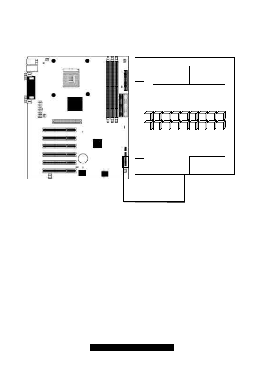
2.1 Front Panel Connector (J20)
15
1317119753116141812108642
Chassis Intrusion (pins 17+18)*
Your chassis will usually come with connectors to install onto the motherboard, such as HDD and
Power LEDs. The Front Panel Connector (J80) has been implemented for such purposes.
Infrared
(IrDA)
IR TX
HM_INTR
GND
GND
GND
NCNCNC
IR RX
RSTSWHDD
SW
VCC
GND
LED
GND
SW
GND
VCC+
Slp LED+
Pwr LED+
PWRSWPWR
LED
* optional feature available on some Trinity i845 models
http://www.tyan.com
9
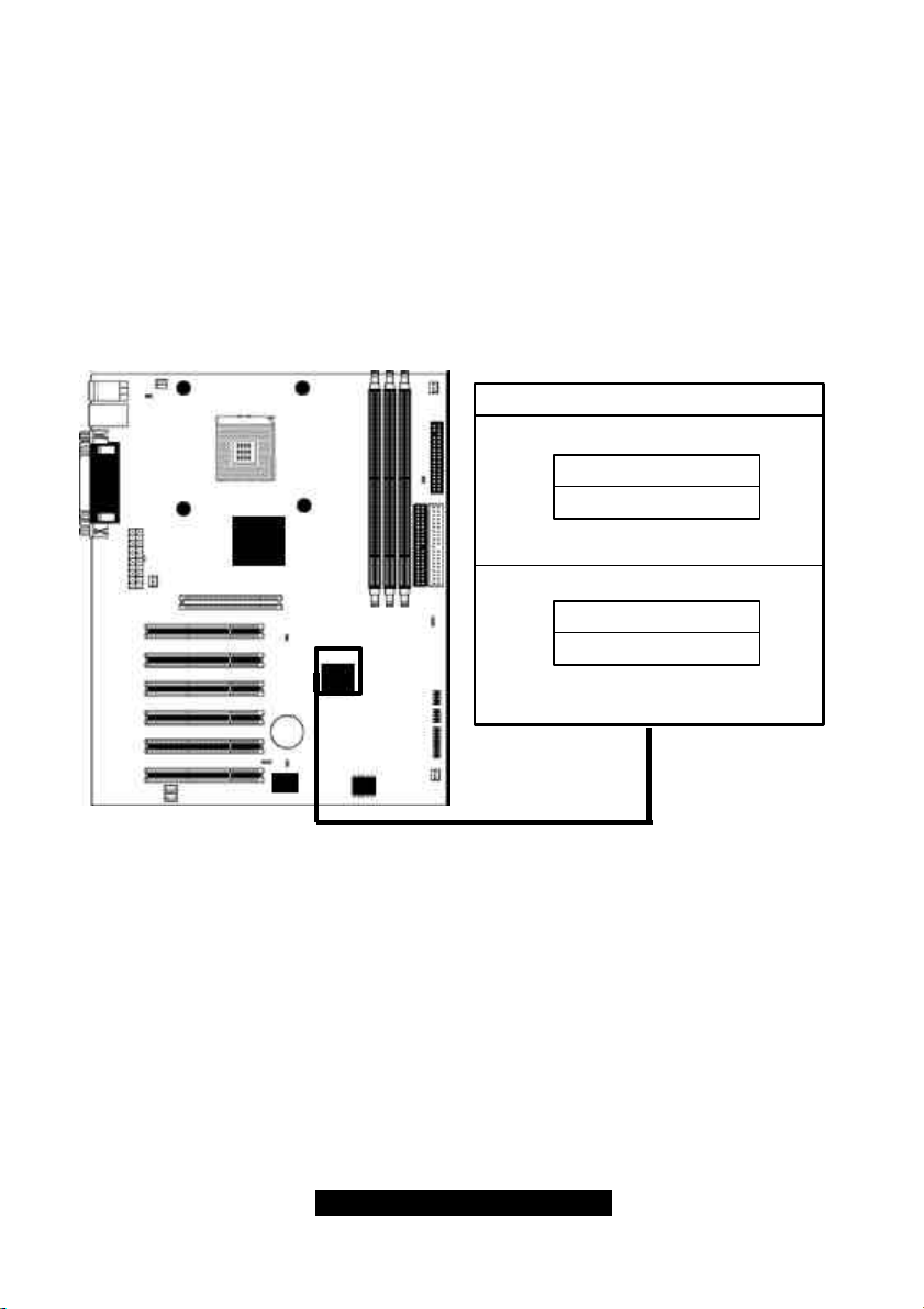
2.2 CMOS Reset (JP1)
CLOSE 1-2
CLOSE 2-3
Normal
Clear CMOS
If you have been locked out of your system because you forgot your password, or set the CMOS
incorrectly, or have just finished flashing your BIOS, you will need to reset the CMOS. The
instructions are as follows:
1. Power off the system
2. Close pins 2-3 on JP1
3. Wait about three seconds
4. Close pins 1-2 on JP1, then power on the system again
By following this procedure, you will erase your password and reset the CMOS. The location of
JP1 is shown in the diagram below.
http://www.tyan.com
10
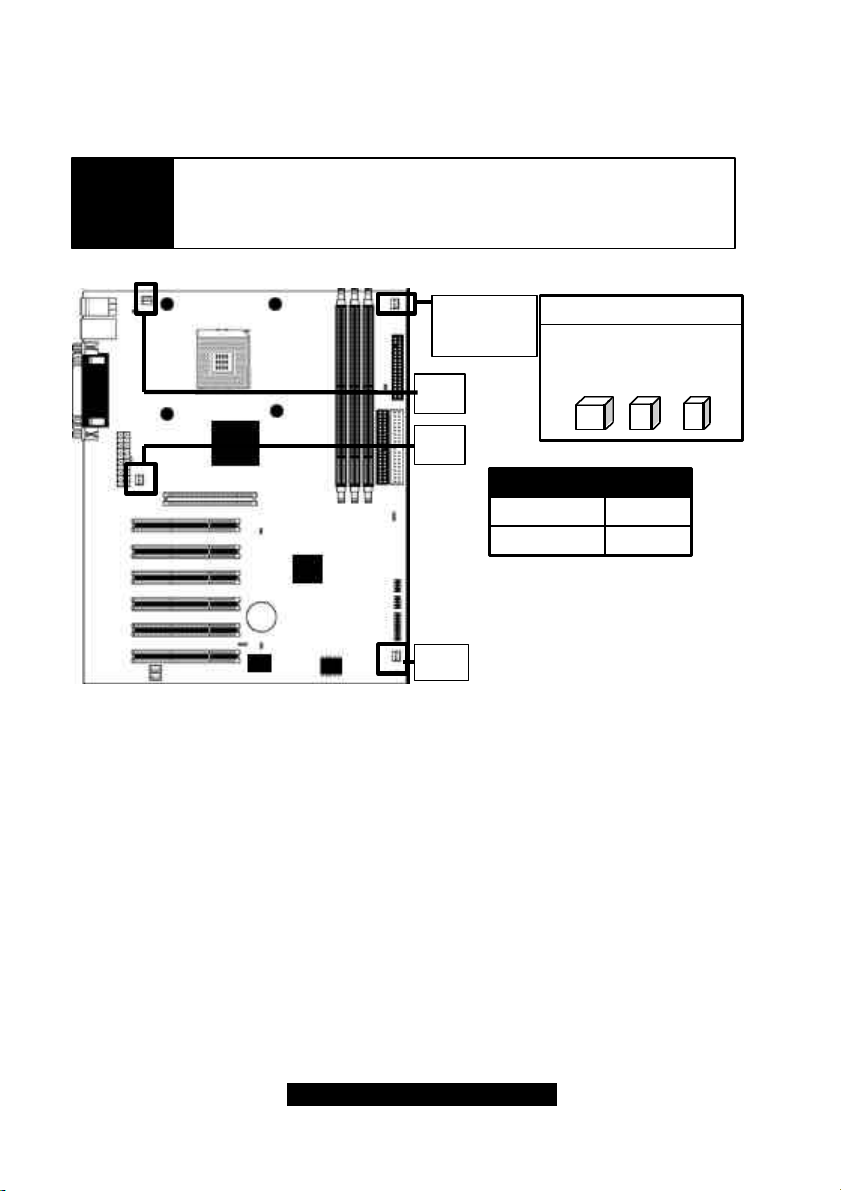
2.3 FAN Connectors* (FAN1, FAN2, FAN3, FAN ALWAYS ON)
+12V
3
These FAN connectors can be used to install cooling devices. FAN1 is for CPU fan.
NOTE
The FAN connectors FAN1, FAN2, FAN3 and FAN4 --- are 12V at 0.3A
and only support cooling fans below or up to that rating. Tyan takes
no responsibility and will not be held liable for damage related to the
misuse of these fan headers.
FAN
ALWAYS ON
FAN1
FAN3
Voltage
Amperage
FAN2
GND
12V
0.3A
SPEED
* For hardware monitoring information related to FAN1, FAN2, and FAN3, please check the
Hardware Monitoring section.
11
http://www.tyan.com
2.5 Thermal Trip header (J5)
•
1
2
This header is used to control the emergency overheat shutdown.
http://www.tyan.com
12

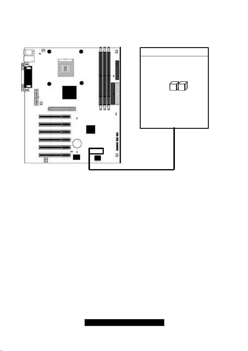
2.6 Boot Block (JP2) – MUST REMAIN CLOSED
2
1
•
Many newer systems come with a feature where a 4 KB "boot block" program is included as part
of the BIOS. This is a tiny piece of code whose job it is to recover from a situation where the BIOS
code is incorrect or corrupted.
If your motherboard supports this feature, when the PC tries to boot and finds the BIOS code
corrupted, the boot block will try to recover the BIOS code, usually by reading it from a speciallyprepared floppy disk. You may have to change a jumper on the motherboard to enable this
capability, and you may need to make use of a "plain vanilla" ISA video card. The boot block will
load the BIOS code and then when you next reboot, the regular BIOS code should be in place and
the problem resolved.
http://www.tyan.com
13
 Loading...