

Page 1

TM
Trinity 450
S2507S
Motherboard User’s Manual
Revision 1.00
Copyright © Tyan Computer Corporation, 2001. All rights reserved. No part of this
manual may be reproduced or translated without prior written consent from Tyan
Computer Corp.
All registered and unregistered trademarks and company names contained in this
manual are property of their respective owners including, but not limited to the following.
Trinity 450 S2507S is a trademark of Tyan Computer Corporation.
AwardBIOS is a trademark of Phoenix Software.
Windows is a trademark of Microsoft Corporation.
IBM, PC, AT, PS/2 are trademarks of IBM Corporation.
Intel, Pentium III are registered trademarks of Intel Corporation.
VIA, Apollo Pro 133A are trademarks of Via Technologies, Inc.
Information contained in this document is furnished by Tyan Computer Corporation and has been reviewed for accuracy and reliability prior to printing. Tyan
assumes no liability whatsoever, and disclaims any express or implied warranty,
relating to sale and/or use of Tyan products including liability or warranties relating
to fitness for a part icula r purpose o r me rchan tabili ty. T yan reta ins th e right to make
changes to product descriptions and/or specifications at any time, without notice.
In no event will Tyan be held liable for any direct or indirect, incidental or consequential damage, loss of use, loss of data or other malady resulting from errors or
inaccuracies of information contained in this document.
Page 2

Table of Contents
Chapter 1: Introduction
Overview ....................................................................................................................4
1.1
Hardware Specifications ............................................................................................5
1.2
Software Specifications ..............................................................................................6
1.3
Technical Support ......................................................................................................7
1.4
Returning Merchandise for Service ............................................................................7
1.5
.............................................................
Chapter 2: Board Installation
2.1
Unpacking ..................................................................................................................8
2.2
Installation ..................................................................................................................8
2.3
How to install our products right... the first time ..........................................................8
2.4
Quick Reference for Jumpers ..................................................................................10
2.5
Map of Motherboard Jumpers ..................................................................................11
2.6
Setting Jumpers .......................................................................................................12
2.6-A
Front Panel Connector .............................................................................................12
2.6-B
CMOS Reset ............................................................................................................12
2.6-C
USB Connector ........................................................................................................12
2.6-D
Cooling Fans ............................................................................................................12
2.6-E
Wake on LAN ...........................................................................................................13
2.6-F
Wake on Modem ......................................................................................................13
2.6-G
Chassis Intrusion .....................................................................................................13
2.6-H
CPU Frequency Settings ..........................................................................................13
2.6-I
Infrared Reserved ................... ............................... ..... ...... ..... ..... ..... ........................13
2.6-J
Soft Power Connector ..............................................................................................14
2.6-K
Hardware Reset Switch Connector Installation ........................................................14
2.6-L
Flash Utility ............................. ..... ..... ..... ...... ..... ............................... ...... ..... ..... ..... ...14
2.7
Mounting the Motherboard in the Chassis ................................................................15
2.8
Installing Memory .....................................................................................................16
2.9
Installing the CPU and Cooling Fan ....................... ..... ................................ ..... ..... ...17
2.10
Connecting IDE and Floppy Drives ..........................................................................20
2.11
Installing Add-on Cards ............................................................................................22
2.12
Connecting PS/2, USB, and Serial Port 1 ................................................................23
2.13
Connecting the Power Supply ..................................................................................24
2.14
Frequently Asked Questions (FAQ) .........................................................................25
Page 4
.............................................................
8
Chapter 3: BIOS Setup
Introduction to the BIOS Setup .................................................................................26
Starting Setup ................... ...... ..... ..... ..... ................................ ..... ..... ...... ..... ..... ........26
Setup Keys ...............................................................................................................27
Getting Help .............................................................................................................27
In Case of Problems .................................................................................................27
Setup Variations ..................................................................... ..... ..... ...... ..... ..... ..... ...28
General Help ..................... ...... ..... ..... ..... ................................ ..... ..... ...... ..... ..... ..... ...28
Main Setup ........................ ...... ..... ..... ..... ...... ............................... ..... ...... ..... ..... ..... ...28
3.1
Standard CMOS Setup ............................................................................................28
3.2
3.2-A
Date/Time ................................................................................................................28
3.2-B
IDE Primary/Secondary Master/Slave ......................................................................28
3.2-C
T able of IDE Device Settings ....................................................................................29
3.2-D
Memory ....................................................................................................................30
2
....................................................................
http://www.tyan.com
26
Page 3

3.3
Advanced BIOS Features ........................................................................................30
3.4
Advanced Chipset Features .....................................................................................32
3.5
Integrated Peripherals ..............................................................................................33
3.6
Power Management Setup .......................................................................................34
3.7
PnP/PCI Setup .........................................................................................................35
3.8
PC Health Status ......................................................................................................36
3.9
Set Supervisor / User Password ..............................................................................36
3.10
Flash Utility ............................. ..... ..... ..... ...... ..... ............................... ...... ..... ..... ..... ...37
Chapter 4: System Resources
Beep Codes .............................................................................................................38
4.1
Displayed Error Messages .......................................................................................38
4.2
Appendix I: Glossary
.......................................................
38
41.......................................................................
Trinity 450 S2507S
3
Page 4

Chapter 1: Introduction
1.1 Overview
The Trinity 450™ is a high p erforman ce motherb oard desi gned fo r server an d perform ance app lications
that require the power of the Intel® P entium® III FC- PGA processor or a Celeron® FC-PGA proce ssor.
This motherboard utilizes the VIA Apollo Pro 133A chipset and can suppo rt CPU speeds of 500 MHz
through 1 GHz and fro nt side bus speeds of 100 MHz or 133 MHz. Please see Tyan’s website for
updates and information concerning CPU information and support:
http://www.tyan.com
This integrated perfo rman c e boa rd is suppo rted in an ATX form factor. Some of the features included are
onboard UltraDMA-33/66/100 support, and south bridge with integrated hardware monitoring.
With I/O and drive controller support onboard, the one 2x/4x mode AGP slot and five 32-bit PCI v2.2 slots
are free for num erous types of add -on e xpansion card s. The four 168-p in unbuffere d DI MM so ckets can
support up to 2GB* of PC100 unbuffered memory or 1.5GB* of PC133 unbuffered SDRAM.
Remember to visit Tyan’s website at http://www.tyan.com. T here you can find information on all of
Tyan’s products with FAQs, distributors list, and BIOS settings explanations.
* 2.0GB total memory @ 4 unbuffered DIMMs only, when using 100MHz SDRAM
1.5GB total memory @ 3 unbuffered DIMMs only, when using 133MHz SDRAM
Check the Tyan website for details on memory compatibility: http://www.tyan.com
4
http://www.tyan.com
Page 5
1.2 Hardware Specifications
Processor Information
Expansion Slots
Chipset Information
Hardware Monitoring
Memory
Integrated PCI IDE
Integrated I/O
Single ZIF PGA370 Socket
Intel Pentium III, Celeron FC-PGA
Onboard VRM
Front side bus support for 66, 100, or 133MHz
One 2x/4x mode AGP slot
Five 32-bit PCI v2.2 compliant slots
Total six usable slots
VIA Apollo Pro 133A chipset
(VT82C694X and VT82C686B)
Integrated hardware monitoring
3-pin Fan Monitoring headers
2-pin External SCSI LED header
Temperature and Voltage Monitoring
3-pin Wake on Modem header
Four 168-pin 3.3V unbuffered DIMM socke ts
Supports up to 2GB@100MHz (4 DIMMS) unbuffered
Supports up to 1.5GB@133MHz (3 DIMMS) unbuffered
Supports PC100/133 SDRAM
Two channel master mode
Supports up to four Enhanced IDE devices
Support for UltraDMA-33/66/100 IDE devices and
ATAPI compliant devices
One floppy connector for up to two drives
Two 9-pin UART serial ports
One 25-pin ECP/EPP parallel port
Four USB ports (two ports via cable - optional*^)
PS/2 mouse and keyboard ports
INTRO
BIOS
Form Factor
Regulatory
* Extra accessories can be purchased at the Tyan Online Store: http://www.etyan.com
^ Please check if your chassis supports a frontside USB port configuration. Check with your chassis
vendor for more details.
Award BIOS 2 Mbit Flash
Auto-detection of memory size
Auto-configuration of IDE hard disk types
User settings of hardware monitoring
Multiple boot options
DMI 2.0 compliant
ATX 2.03 12” x 9.6” (304.8 x 243.84 mm)
One 20-pin ATX power connector
Stacked mouse & keyboard ports
Stacked two USB ports
Two serial ports
FCC Class B (Declaration of Conformity)
European Community CE (Declaration of Conformity)
Taiwan BSMI Notice (Declaration of Conformity)
Trinity 450 S2507S
5
Page 6

1.3 Software Specifications
OS
Operates with Windows 98/SE/ME,
Windows NT/2000
6
http://www.tyan.com
Page 7

1.4 Technical Support
If a problem arises with your system , you should turn to your dealer for he lp first. Your system has most
likely been configure d by t hem, a nd the y should have the best ide a of wh at har dware and so ftwa re your
system contains. Hence, they shou ld be of the mo st assist anc e. F urt her more, if you p urch ase d you r system from a dealer near you, you can actual ly bring your system t o them to have it service d, instead of
attempting to do so yourself (which can have expensive consequences).
Help Resources:
1. See the FAQ and beep codes section of this manual.
2. See the Tyan website for FAQ, bulletins, driver updates, and other
information: http://www.tyan.com
3. Contact your dealer for help BEFORE calling Tyan.
4. Check the Tyan user group: alt.comp.periphs.mainboard.tyan
1.5 Returning Merchandise for Service
During the warranty pe riod, contact your d istributor or system ve ndor FIRST for any product prob lems.
This warranty only covers no rm al cust ome r use and does n ot cove r da mag es i ncu rr ed du ring shipp i ng or
failure due to the alteration, misuse, abuse, or improper maintenance of products.
NOTE: A receipt or cop y of your invo ice ma rked with t he da te of pur chas e is re quir ed be fore any
warranty service can be rendered. You may obtain service by calling the manufacturer for a
Return Merchandis e Authorization (RM A) number. The RMA number should be prominently displayed on the outsid e of the sh ipp in g ca rt on an d th e p ack ag e sh ou ld be m ail ed pr ep aid . Tyan will
pay to have the board shipped back to you.
INTRO
Trinity 450 S2507S
7
Page 8
Chapter 2: Board Installation
2.1 Unpacking
The retail motherboard package should contain the following:
Trinity 450 motherboard
34-pin floppy cable
ATA-66/100 IDE cable (with blue connector)
Trinit y 450 use r’s ma nua l
Tyan driver CD
2.2 Installation
You are now ready to install your mothe rb oar d. T he m oun ti ng ho le p atte rn of the Trinity 450 matche s the
ATX board specifications, so your chassis must be capa ble of supporting an ATX board (check the motherboard dimensions provided on p. 5).
2.3 How to install our products right.. the first time.
Question: what’s the first thing I should do?
The first thing you should do is read the user’s manual. It contains important information wh ich will make
configuration and setup much easier, as well as provide information on device installation and component
set up.. By reading through the manual completely before installing your motherboard, you will have a
complete overview on the installation.
8
http://www.tyan.com
Page 9
Here are some safety tips:
(1) Ground yourself properly before removing your motherboard from the antistatic bag. Unplug
the power from your computer power supply and touch any metal part on the computer case. (You
might also want to wear a grounded wrist strap.)
(2) Hold the motherboard by its edges and do not touch the bottom of the board.
(3) Avoid touching motherboard components, IC chips, connectors, and leads.
(4) Avoid touching pins of memory modules and chips.
(5) Place motherboard on a grounded antistatic surface or on the antistatic bag.
Having reviewed the precautions above, the next step is to take the motherboard out of the cardboard box
and static bag, hold it by its edges, and pl ace it on a grounded a ntistatic surface, com ponent side up.
Inspect the board for damage.
NOTE: DO NOT APPLY POWER T O THE BOARD IF IT HAS BEEN DAMAGED!
Press down on any of the socketed ICs if it appear s that they are no t properly sea ted (the boa rd should
still be on an antistatic mat). Do not touc h the bottom of the boa rd. Remember, don’t take any elect ronic
device out o f it s p ro t ect i v e ba g un t i l y o u a r e r e ad y t o a c t ual l y i n s tal l i t int o t he c o mp ute r ca s e . If y o u do n ot
ground yourself, you r isk zappi ng the mothe rboard o r adap ter card . Sub sequen t prob lems may not arise
immediately because electrostatic discharge, unlike physical damage, causes the device to fail over time.
INSTALL
Installation Steps
1. Set jumper s (if necessary)
2. Mount motherboard in chassis
3. Install me mory
4. Install CPU and cooling fan(s)
5. Connect IDE and floppy drives
6. Install add-on cards
7. Connect PS/2, USB, and serial devices
Trinity 450 S2507S
9
Page 10
2.4 Quick References for Jumpers
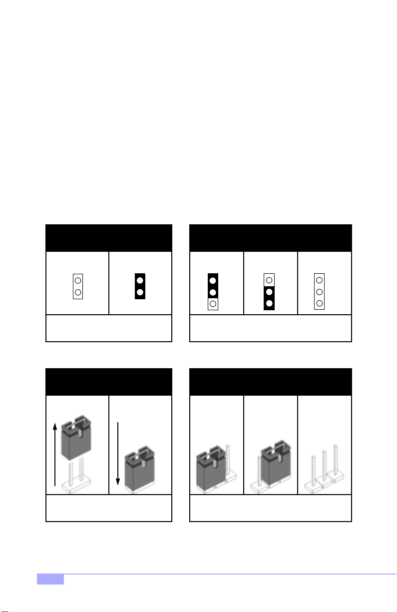
In this manual, the term “close d” and “on” are used wh en referring to jumpers (or jumper pins) that are
active; “open” and “off” a re u s ed whe n re fer ring to j u mp ers (or j um per pin s) that are inactive. See Figure
2.0a and Figure 2.0c for examples of “on” and “off” pins and jumpers.
Jumpers and pins are connec ted by slipping the plastic jum per connector over the top of tw o adjacent
jumper pins (indica ted b y 1-2 or 2-3 ). Th e met al r od insid e the plast ic shell bridg es the gap b etween the
two pins, completing the circ uit. See Figure 2.0b and Figure 2.0d for more examples of 3-pin jumper
connections. NOTE: The small number “1” indicates pin 1.
The tables and maps on the following pages will help you set the jumpers for CPU speed, infrared, and
external connector pin assignments, among others. The miniature motherboard maps will help you locate
the jumpers on your board. Full page maps of the motherboard can be found on the next two pages.
2-pin jumpers
off on
Figure 2.0a
(overhead view)
1-2 2-3 open
3-pin jumpers
1
2
3
Figure 2. 0b
(overhead view)
2-pin jumpers 3-pin jumpers
1-2 2-3 openoff on
11
Figure 2. 0c
(front angle view)
Figure 2. 0d
(front angle view)
1
2
3
1
2
3
10
http://www.tyan.com
Page 11
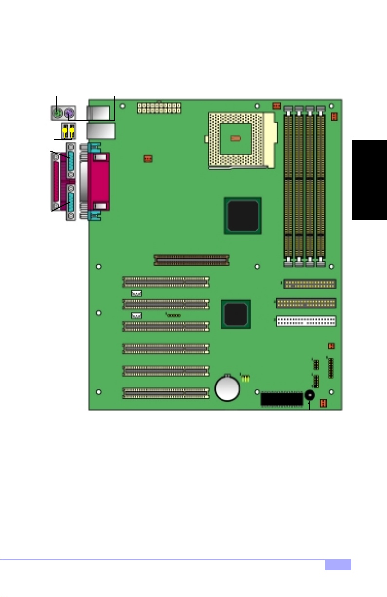
2.5 Map of Motherboard Jumpers
Keyboard port
(lower port)
USB
Ports
port
Serial
port
Parallel
port
Serial
Mouse port
(upper port)
JWOL
JWOM
ATX Power
Connector
FAN4
2x/4x AGP slot
IR
ZIF Socket370
VIA
VT82C694X
chipset
JP11
Battery
FAN3
FDD Connector
Primary IDE
Secondary IDE
2 Mbit Flash
Speaker
JP9
FAN1
INSTALL
JP3
J1
USB1
FAN2
Trinity 450 S2507S
11
Page 12
2.6 Setting Jumpers
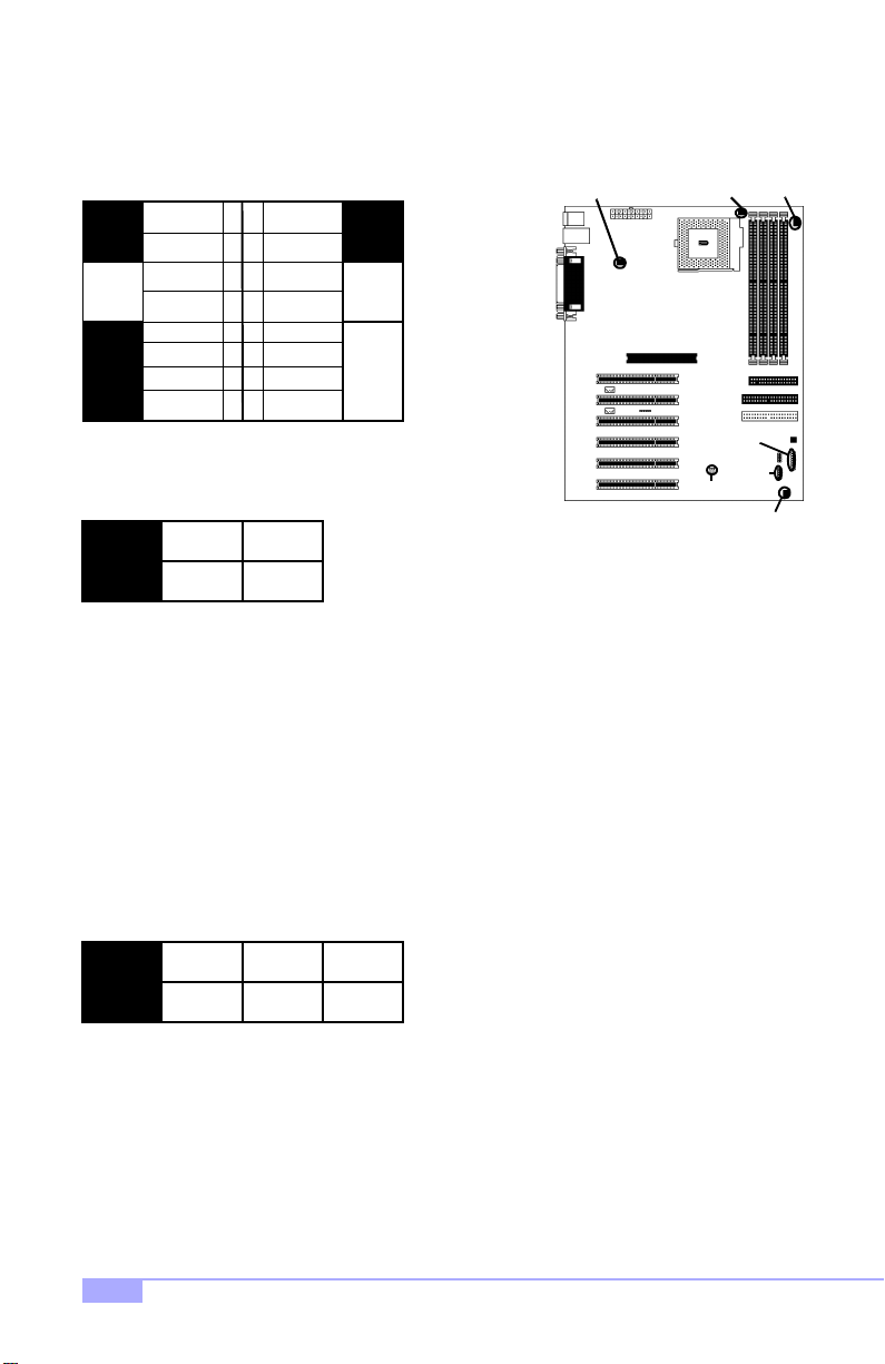
2.6-A. Front Pane l Co nn ec to r (J1)
VCC
LED
HDD
LED
Ground Switch
Switch
Reset
Switch
IR +5V
IR RX
Ground
IR TX no connect
Infrered
2.6-B. CMOS Reset (JP11)
1-2
12
34
56
78
910
11 12
1314
1516
Pwr LED+
Slp LED+
Ground
SN_NMI
Ground
no connect
2-3
FAN4
LEDs
Pwr/Slp
Power
Switch
JP11
FAN3
USB1
FAN1
J1
FAN2
JP11
Normal
If you have been lo cked out of your system because you forgot your password or set the CMOS incorrectly, or have just finished flashing your BIOS follow the instructions below.
By following this procedure, you will erase your password and reset the CMOS.
2.6-C. USB Connector (USB1)^
This connector is for the additional USB connector*^ (which adds two more ports^ on a second USB
channel^). Please keep in mind that pin 1,2 are +5VCC, and pin 9,10 are GROUND (see p.11 for pins).
Clear
1. Power off the system, and disconnect the power supply
2. Close pins 2-3 on JP11 (see mini-map for location of JP11)
3. Wait about three seconds
4. Move jumper back to 1-2, then power on the system again
2.6-D. Cooling Fans (FAN1, FAN2, FAN3, FAN4)
1
FAN
Ground2+12V3Speed
In addition to installing your CPU, Tyan highly recommends that you install a CPU fan/heatsink combination, and if needed , additi onal chassis fans. To this end Tyan has provided seve ral conne ctors to p ower
the fan(s), as well as the fan pinout (shown above). Here is some information you may find useful:
- We recommend you use FAN3 and FAN4 for the CPU cooling fans
- All other fan connectors are left to the user’s discretion
* Extra accessories can be purchased at the Tyan Online Store: http://www.etyan.com
^ Please check if your chassis supports a frontside USB port configuration. Check with your chassis
vendor for more details.
12
http://www.tyan.com
Page 13
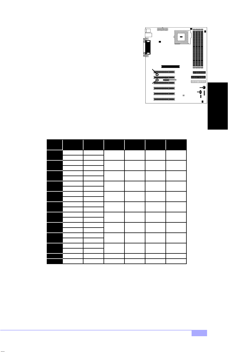
2.6-E. Wake on LAN (JWOL)
This is the connector for the Wake on LAN function.
2.6-F. Wake on Modem (JWOM)
This is the connector for the Wake on Modem function.
2.6-G. External SCSI LED (JP3)
If your peripheral supports a feature for hassis intrusion, you
can use this connector to use that feature. If activity is
detected from the peripheral and this feature is connected,
the activity will be displayed on the chassis front side LED.
2.6-H. CPU Frequenc y Se ttings (JP9)
NOTE: The following settings are only valid if a non-retail/engineering sample CPU is installed. Retail
CPU settings will automatically be detected and used accordingly.
Ratio
Bus
Speed
100
3
133 400
4
5
6
7
8
100
133 467
100
133 533
100
133
100
133
100
133
100
133
100 650
133
100
133
100
133
100
3.5
4.5
5.5
6.5
7.5
8.5 850100 open close open close
CPU
Speed
300
350
400
450
600
500
667
550
733
600
800
866
700
933
750
1000
800
Pins 1-2 Pins 3-4 Pins 5-6 Pins 7-8
close open close close
close close
open
open
open
open open
close close close
close close
close close
close
open openclose close
JWOL
JWOM
open open
close close close
close close
open
open
open
open
close close
open
open open
open open
close
open
open
IR
JP3
JP9
INSTALL
2.6-I. Infrared Reserved (IR)
This is a reserved connector for IR functions.
Trinity 450 S2507S
13
Page 14

2.6-J. Soft Power Connector
The soft power connector is part of jumpe r block J1 (p ins 6 to 8). This bo ard uses the ch ipset for pow er
management, including tur ning on and off the system. If the power b utton function option in the BIOS
Power Management me nu is set to “On/Off” (wh ich is the d efault), pr essing the p ower button once after
the BIOS has booted up will turn the system on a nd off. If the power button functio n is set to Suspend,
pressing the power button once will wake up t he system or send it to Suspend mode. In this case, you
cannot turn the system off unless yo u shut d own through the Windo ws oper ating system o r you ho ld the
power button down for four seconds.
2.6-K. Hardware Reset Switch Connector Installation
The reset switch on your chassis case provides you with the Hardware Reset function, which is the same
as power on/off, except that the system will immediately execute a cold start afte r the reset button is
pushed.
2.6-L. Flash Utility
You can upgrade the BIOS of this mo therboard by using t he Flash Utilit y (see p. 37). Check the Tyan
website for details: http://www.tyan.com
* check the Tyan website for updates: http://www.tyan.com
14
http://www.tyan.com
Page 15
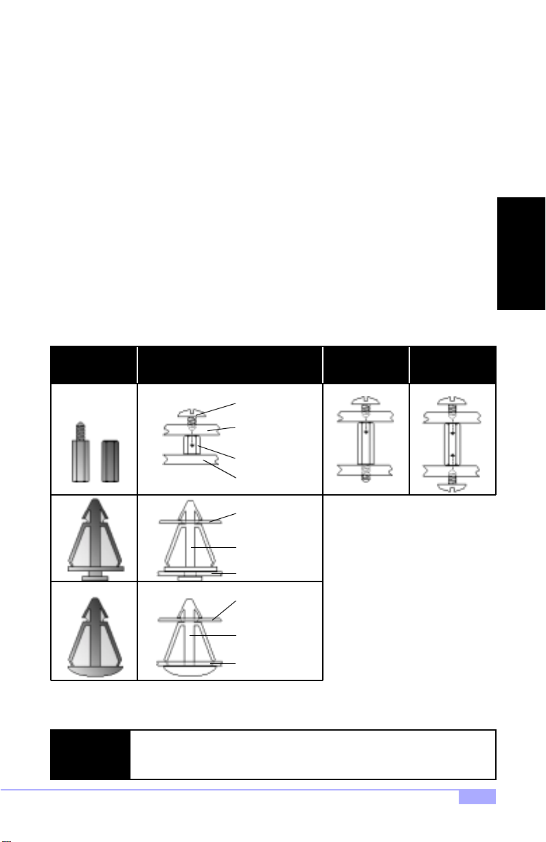
2.7 Mounting the Motherboard into the Chassis
Your chassis may include mounting hardware. If mounting hardware w as included, yo u can use the fo llowing examples to help you in installing your motherboard into the chassis.
The chassis may have com e wit h th e stud s int egr ate d in to t he cha ssis wa ll, so in t hose ca ses you wou ld
only need to use scre ws (p ossibly i nclude d with you r chass is) to instal l the m other board . See the ex amples (Figure 2.0, shown below) for more details.
If the chassis includes mounting hardware without the studs pre-installed, then you will need to install the
motherboard using the mounting hardware as shown in t he examples below. Remember not to overtighten any of the sc rews, or you might risk breaking i nternal tr aces in the su rroundi ng area, or damage
the motherboard in some ot her way .
Other examples of how to install your motherboard using other hardware (that may or may not have been
included with your chassis) are shown below.
One solution for installing motherboardType of hardware Another solution Another solution
screw
motherboard
base
stud
chassis wall
motherboard
base
standoff
chassis wall
motherboard
base
INSTALL
The diagrams above are only representative of a few solu tions for installing a
NOTE:
motherboard into the chassis. The installation procedure fo r installing your motherboard may differ.
Trinity 450 S2507S
standoff
chassis wall
Figure 2.0
15
Page 16
2.8 Installing Memory
Please keep in m ind t hat although some m em or y m od ules m ay ap pear to be high -q ualit y, they may contain inferior or subs tandard parts . The type of m emory you choo se to install sho uld be checked ag ainst
the memory compatibility list, which is available from Tyan’s website at http://www.tyan.com
Memory Installation Procedure
Here are some details of memory installation for this board:
At least one unbuffered DIMM must be installed for the system to POST.
The motherboard supports 64MB, 128MB, 256MB, and 512MB PC100/133 SDRAM.
All installed memory will be automatically detected, so there is no need to set any jumpers.
The motherboard supports up to 1.5 (3 DIMMs)* or 2 GB (4 DIMMs)* of memory.
Step
Step
Step
* 2.0GB total memory @ 4 unbuffered DIMMs only, when using 100MHz SDRAM
1.5GB total memory @ 3 unbuffered DIMMs only, when using 133MHz SDRAM
Check the Tyan website for details on memory compatibility: http://www.tyan.com
Insert the DIMM by pushi ng the module in to the socket with e ven force. Do not insert one
1
end and then the other : install the whole modul e at once or you might bend the DIMM pins.
Make sure the DIMM is securely seated.
Line your module up so that the pins fit into the socket. There is only one way your DIMM can
2
fit properly. Make sure that the short row of pins is lined up with the short gap in the DIMM
socket.
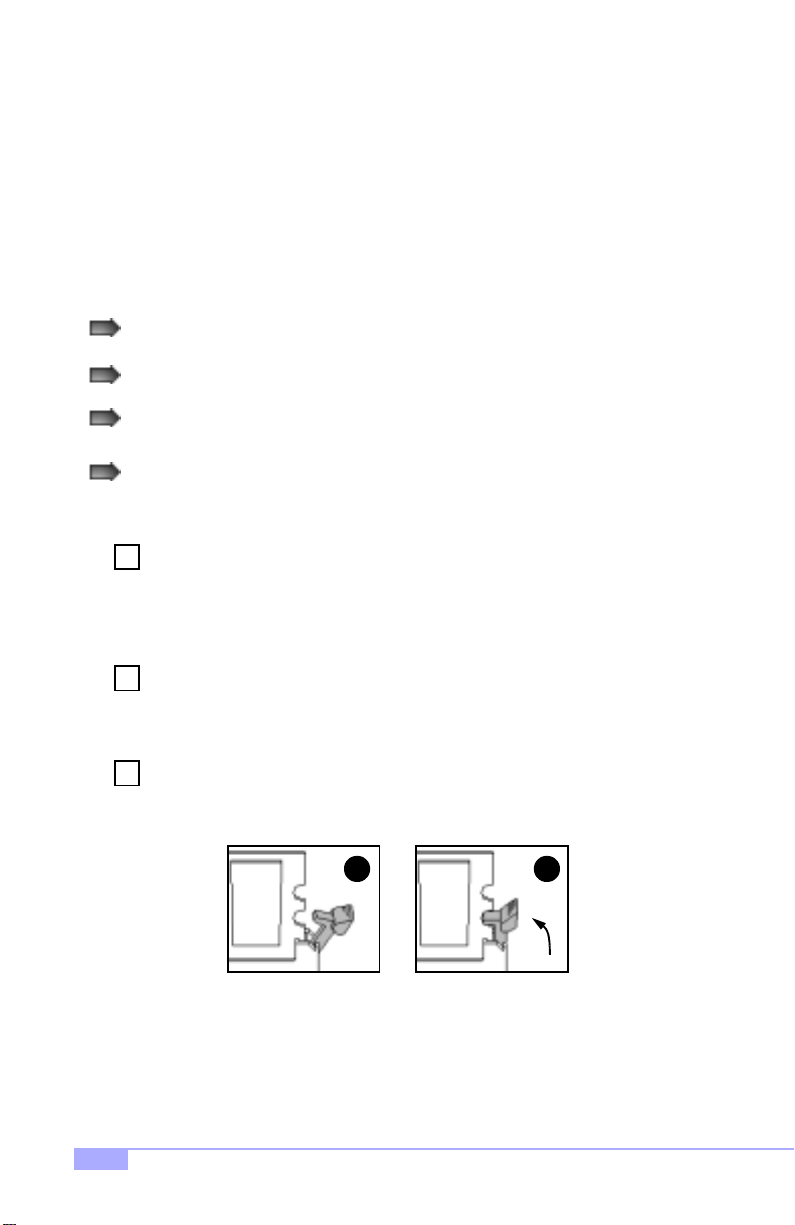
Lock the DIMM into place by pu shing the clips back on either end of th e socket onto the
3
notches in the ends of the DIMM (see pictures below for details).
1
2
16
http://www.tyan.com
Page 17
Removing a DIMM
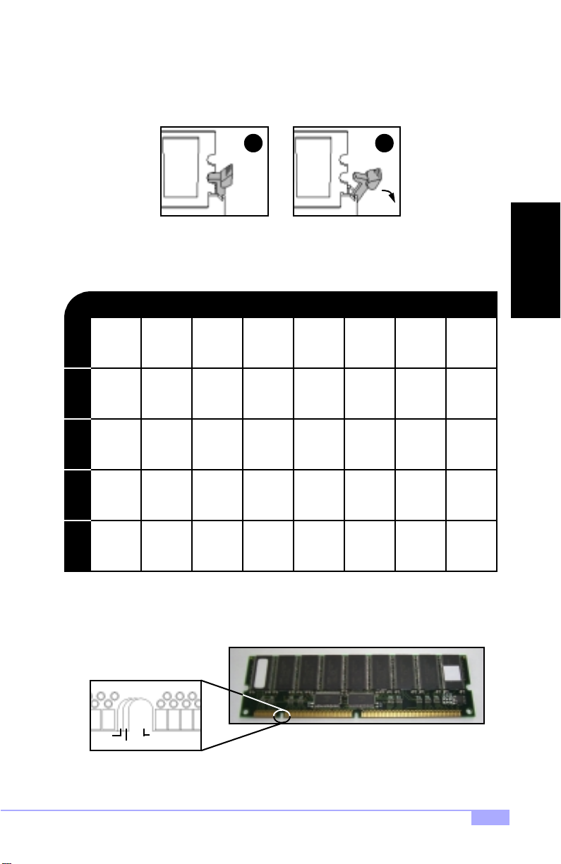
Removing a DIMM is just the reverse: simpl y pu ll back the cl ips fro m the DIM M (see pictur es bel o w), and
carefully pull the module straight out. Place the DIMMs in an anti-static bag as soon as you remove them
to avoid static damage.
21
Suggested Memo r y Co nf i g ur at ion s
The table below shows some of the po ssible memory configuratio ns. Not all possible c onfigurations
are listed. Your memory configuration may differ from one or more of the combinations shown below.
2GB* at 100 MHz combination or 1.5GB* at 133 MHz combination
INSTALL
64MBx1
DIMM 1DIMM 2DIMM 3DIMM 4
0
64MBx1
0
0
64MBx1
64MB
TOTAL
The 168-pin DIM Ms (Du al I n-li n e M em or y M odu l es) m ust be of the 3.3V PC100/PC133 u nb uf fe re d var iety. The notch position in the SDRAM key position will tell you whether or not a DIM M is unbuffered (see
Figure 2.1 below). All installed memory will be auto-detected, so there is no need to set any jumpers.
buffered
unbuffered
RFU
* 2.0GB total memory @ 4 unbuffered DIMMs only, when using 100MHz SDRAM
1.5GB total memory @ 3 unbuffered DIMMs only, when using 133MHz SDRAM
Check the Tyan website for details on memory compatibility: http://www.tyan.com
128MBx1
0
0
128MBx1
0
128MBx1
64MBx1
0
192MB 256MB
0
00128MBx1
256MBx1
0
384MB
Figure 2.1
0
0
512MBx1
512MBx1
1024MB
512MBx1
0
1024MBx1
0
1536MB
0
1024MBx1
0
1024MBx1
2048MB128MB
Trinity 450 S2507S
17
Page 18
2.9 Installing the CPU and Cooling Fan
Intel Pentium III FC-PGA processors (500 MHz through 1 GHz) or a single FC-PGA type Celeron processor can be used on this board. For more information on CPU compatibility, check Tyan’s website at:
http://www.tyan.com.
When installing your CPU, remember the following:
The CPU is a sensitive electronic component and can easily be damaged by static electricity
Do not touch the CPU pins with your finger s
You should be able to insert the CPU into the socket with virtually no force
Do not press down hard on the CPU as you might bend or break pins, or otherwise damage the
CPU
The CPU voltage will automatically be detected by the motherboard, so there is no need to set any jumpers or BIOS setting.
Installing the Intel Pentium III FC-PGA CPU
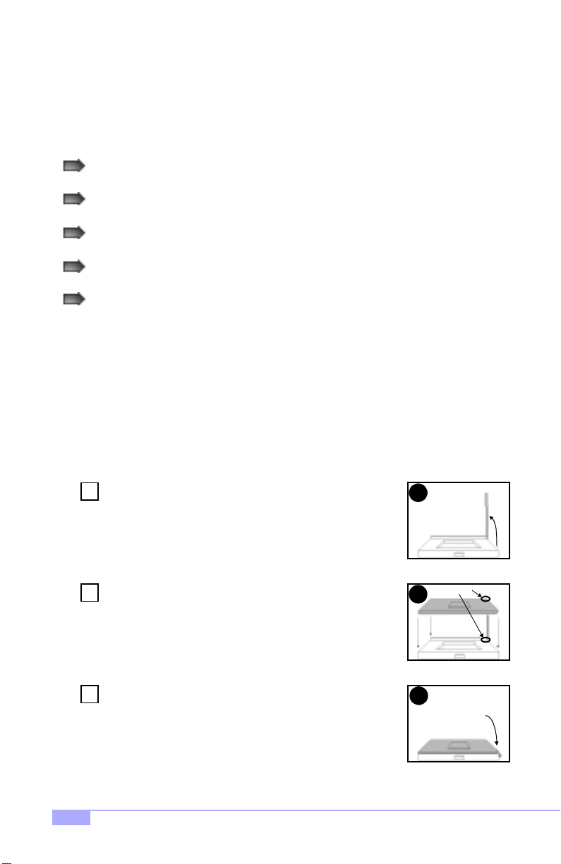
Before installing the CPU, check it for any visible damage. Make sure none of the pins ar e bent or missing. Be sure where Pin 1 is on both the CPU and the socket. The following steps each have a corresponding picture next to it to help guide you through the installation.
Step
Step
Step
18
Carefully lift the arm of the ZIF socket until it is at a 90 degree angle
1
pointing away from the motherboard. Be very careful not to damage
any components that might be next to the socket.
There are two beveled corners on the CPU, which will match the
2
two angled corners on the socket. Carefully install the CPU by lining
both Pin 1 on the CPU an d Pin 1 on the socket, ma king sure the
pins actually fit into the socket. Do not force the CPU into the
socket: check the pin alignment of CPU pins to socket holes.
Push down lightly on the CPU while lowering the arm on the socket
3
to secure the CPU (se e right). A squeaking noise may be he ard
while lowering the arm, or the socket may make a ‘click’ noise when
the arm is locked into position: these noises are normal.
1
Pin 1
2
Arm moves down
3
to lock CPU
http://www.tyan.com
Page 19
Installing the Cooling Fan
After the CPU has been installed, you will need to install the proper co oling de vice for the CPU. This
device, a heatsink/fan com bination , can be purc hased at ma ny compute r retail store s. Installat ion of the
cooling device may vary depe nding on the fan manufacturer ’s design. You should also take space into
consideration when in stall a c ooli n g d evice : m ake su re th e cooling device is no t to o big, or e l se y ou ma y
end up damaging components around the CPU socket.
Tyan highly recommends that you use some type of
thermal compound (available from computer retail
stores), between the CPU and heat sink, to maximize distribution of heat away fr om the CPU. Please use extra
caution when installing any type of clamp-style fan, or
else damage may occur to the CPU sock et, and/or the
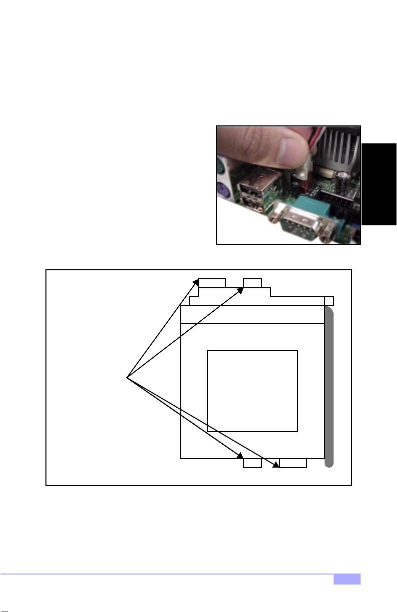
CPU itself. See Figure 2.2 (see right) for a n example o f
how to connect the cooling fan’s power supply. Another
diagram has also be en pro vi de d be low, to aid in C PU fan
installation onto the socket. Check with your cooling
device vendor for more details about installation.
Figure 2.2*
INSTALL
Can be used to install
a cooling device
Mounting points on the CPU socket
Installing Chassis Fans
Alternatively, if you wish to also install chassis fans for increased cooling, we have provided headers to
power those fans as well (see p. 12, section 2.6-D). Chassis fan installation will vary depending on your
chassis manufacturer’s design. Please check with your chassis manufacturer for details on proper chassis fan installation.
* image may not be representative of your motherboard
Trinity 450 S2507S
19
Page 20
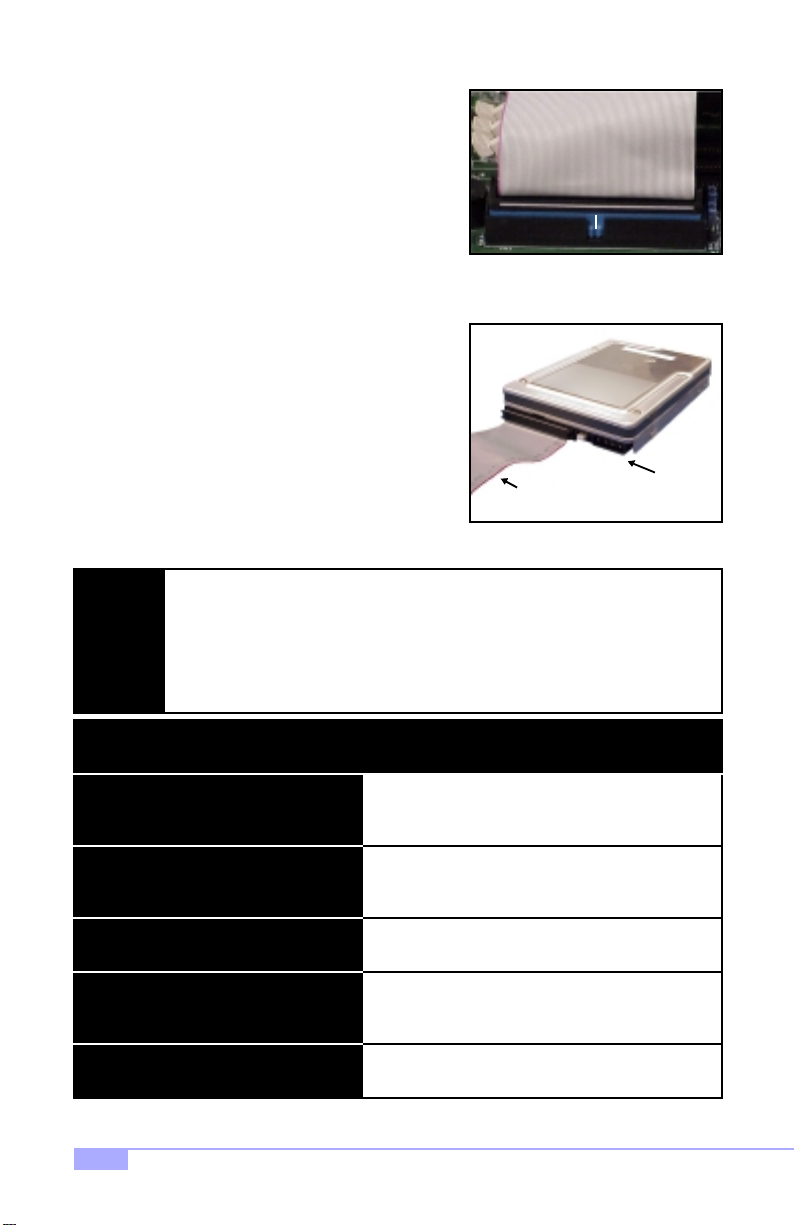
2.10 Connecting IDE and Floppy Drives
A variety of IDE and ATAPI-compliant devices* can be
installed on this motherboard, such as hard disk drives
(HDDs) and CD-ROMs.
Please keep in mind that on this motherboard, the primary IDE
connector is BLACK, and the secondary IDE connector is
WHITE. See Figure 2.3 (right) for an example of the IDE cable
properly connected to the motherboard. Consult the documentation that came with your IDE/ATAPI device, or contact the
device’s manufacturer for more details on installation.
Also see Figure 2.4 (right) for an example of the HDD with the
IDE cable installed. Please note that UltraDMA-66 IDE HDDs
require a special 80-wire cable which has additional grounding
wires. This cable h as be en inclu ded w ith th is moth erboa rd for
your convenience. The UltraDMA-66 cable is upwards compatible with UltraDMA-100 IDE HDDs, and backwards compatible with UltraDMA-33 and legacy IDE HDDs.
The BLUE end of the ATA-66 cable must connect to the motherboard. The black connector on the ATA-66 cable is for the master HDD, and the gre y connector is for the
NOTE:
Some symptoms of incorrectly installed HDDs are...
slave HDD. See Figure 2.3 (above) for an example of installation o n the motherboard.
Only Tyan-approved cables are recommended for this mo the rbo ard . If you a re usi ng
an existing configuration with older cables, your system might not function pro perly.
Use only Tyan-approved cables (i.e. the ones included with your mothe rbo ar d).
HDDs are not auto-detected
May be a Master/Slave configuration problem, bad
IDE cable, or BIOS mis-configuration. Consult the
HDD documentation or contact your HDD vendor.
Blue end of ATA-66 cable
Figure 2.3
Colored stripe
indicates Pin 1
Power
Figure 2.4
Hard Disk Drive Fail message at bootup
No video or beeps during bootup
HDD lights are constantly on
HDD does not power on
* ATAPI-compliant devices may not work with the Promise IDE RAID connectors. Check the Tyan website
for updates and information: http://www.tyan.com
20
May be a bad cable or lack of power going to the
drive. Check the cables for damage and bad connections.
Usually means the cable has been installed backwards.
Bad IDE cable or defective drives/motherboard. Try
another HDD, or contact your HDD vendor.
Check power cables and cabling. May be a bad
power supply or IDE drive problem.
http://www.tyan.com
Page 21
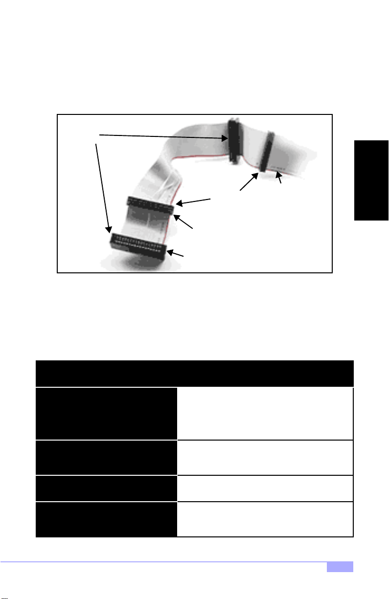
Connecting Floppy Drives
Pin 1 on the floppy cable is usu ally denoted by a red or colored strip e down one side of the cable. See
Figure 2.5 (b elow) for an example of a f loppy cable. Most of the curren t floppy drives on the marke t
require that the cable be instal led with th e colored str ipe positi oned ne xt to the power connector. In most
cases, there will be a key pin on the cable which will force a proper connection of the cable.
Drive B:
Colored stripe
Drive A:
3.5” connector
5.25” connector
indicates Pin 1
Figure 2.5
The first floppy (denote d as A:) is usua lly attach ed to the en d of the cable with the twist i n it. See Figure
2.5 (above) for an e xam ple. Drive B: is usually con ne cted to the middle of the cabl e . Ref er to your floppy
drive’s installation instruc tions, or contact your d ealer if you are unsure abou t how to attach the flopp y
drive(s). Remember, you can only have 2 floppy drives connected at any given time.
INSTALL
Some symptoms of incorrectly installed FDDs are...
FDDs are not auto-detected
Floppy Drive Fail mes sag e at bo otup
FDD does not pow er on
FDD light is constantly on
Trinity 450 S2507S
Usually caused by faulty cables, cables put in backwards, or a bad floppy or motherboard. Try another
floppy drive to verify the problem or try another
cable. Also check to see if the onboard floppy is
enabled in the BIOS.
The cable, floppy, or motherboard may be faulty. Try
another cable or floppy drive to verify.
Check power cables and cabling. May be a bad
power supply or IDE drive problem.
Usually signifies that the cable is on backwards.
Reverse the cable at the floppy drive end and try
again.
21
Page 22
2.11 Installing Add-on Cards
There are a few rules you need to follow when installing add-on cards. In order to assure proper operation
and a quick installation, adhere to the following guidelines:
If you are going to install a PCI-bus interface card on your system, be aware that any one of the
five PCI slots can support a Master or Slave device.
NEVER force a card into a slot. If it doesn’t fit, look at the socket on the motherboard to make
sure there are no wires or other obstructions to the slot.
NEVER plug an ISA card into a PCI slot. You will void your warranty and damage your system
board if you do this.
When plugging the card in, especially when installing long cards, try to push the entire card in at
one time. Don’t force one end of the card into the socket first and then the other, or a rocking
motion between the card and the slot might occur, and could damage the pins within the socket.
Make sure the cards are seated securely into their slots.
Before turning on the system, make sure no cards are touching.
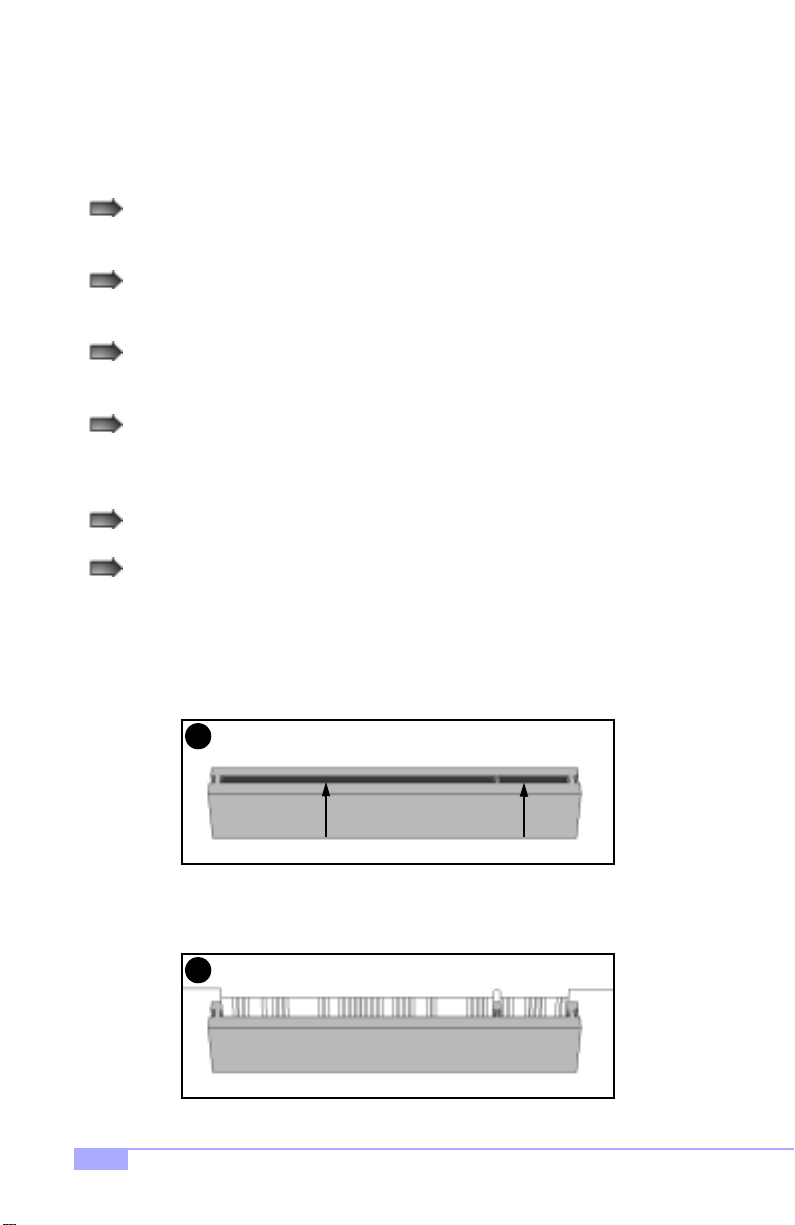
When installing the add-on cards, make sure the cards are installed with even force; do not insert one
end and then the other. See the before (Figure 2.6a) and after (Figure 2.6b) example ins ta ll a t ion i mag es
below for details.
22
1
Check orientation of card when installing
Figure 2.6a
2
Push card down with even force
Figure 2.6b
http://www.tyan.com
Page 23
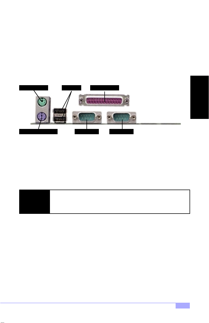
2.12 Connecting PS/2, USB, and Serial Devices
This motherboard includes ports for PS/2 mouse and keyboard, Universal Serial Bus (USB) devices, and
serial and parallel* devices. Please note that the upper PS/2 port is the mouse port, and the lower PS/2
port is for the keyboard (see Figure 2.7 below).
The PS/2 connectors are probably quite familiar to you, while the USB connectors may not be. A USB
port can function as a serial, parallel, mouse, keyboard, display, or joystick port. It is capable of supporting
up to 127 daisy-chained peripheral devices. All external ports are labeled in Figure 2.7, shown below.
PS/2 Mouse Port USB Ports
Parallel Port
INSTALL
PS/2 Keyboard Port
Serial PortSerial Port
Figure 2.7
Connecting Serial and Parallel Ports
The serial and parallel ports can be used to connect various devices such as a mouse or printer. The connectors can only be connected one way: be sure and check the orientation of the connector before installing it into the port.
When plugging in y our keyboa rd an d mou se, or when plug ging i n any thing i nto a
NOTE:
serial or parallel* port, m ake sur e that th e power is off. Conn ecting th ese device s
and ports while the power is on is called hot plugging and may damage your system and/or external devices that you are trying to install.
Trinity 450 S2507S
23
Page 24
2.13 Connecting the power supply
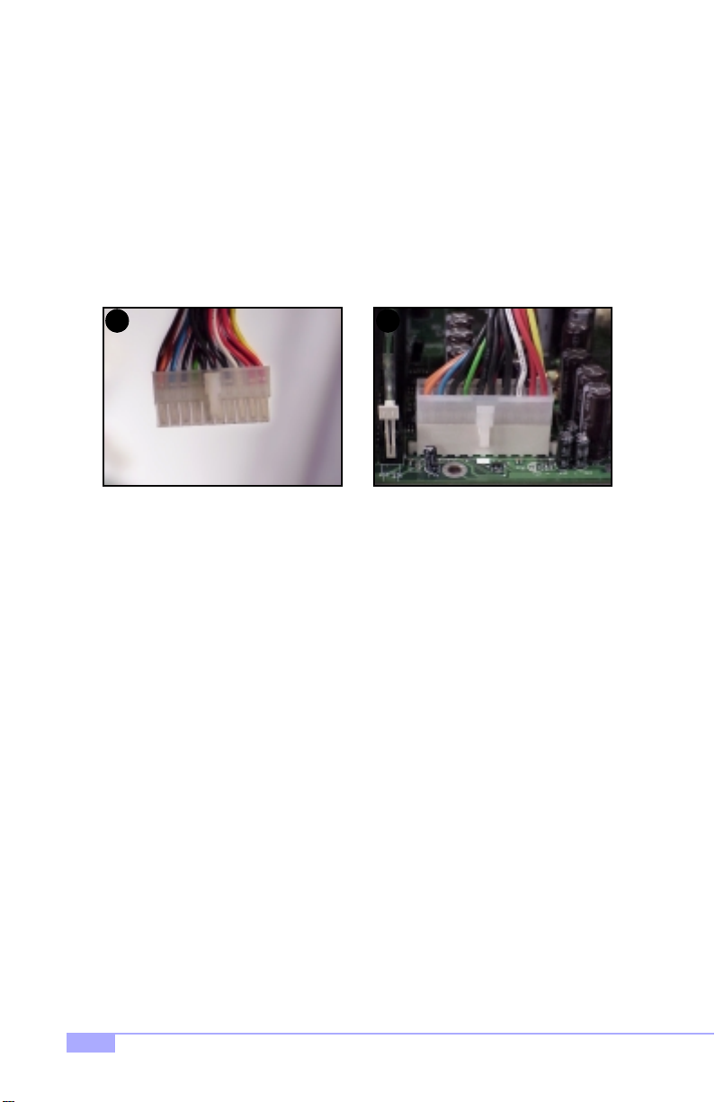
This motherboard requires an ATX power supply. Tyan recommends using one that conforms to industry
standard Revision 2.01. The images below show the ATX power connector before (Figure 2.8a) and after
(Figure 2.8b) it has been plugged in. The clip on the power connector should lock over the tab on the
onboard connector. You shouldn’t be able to plug the power connector in any other way but just to be
safe, make sure it looks like Figure 2.8b. Make certai n that you do not miss connecting any of the pins
because if you do, you will void your warranty and possibly cause damage to yourself and/or your motherboard when the power is turned on. After connecting the power, make sure the connector is seated
firmly into its socket so it will not become loose or fall off when the computer is jostled or moved.
1 2
Figure 2.8a
You are done!
Other than checking the jumper settings and cable connections, and putting the case back on, you are
done. Installing a new motherboard may seem difficult, but by following these directions, you should have
a fairly uneventful time installing our products. If you do encounter problems, your dealer will be able to
help you, or you can consult one of our many technical support resources (see p. 7).
* image may not be representative of your motherboard
Figure 2.8b*
24
http://www.tyan.com
Page 25

2.14 Frequently Asked Questions (FAQ)
Q: My system sometimes becomes unstable. How should I check the system?
A: The first thing to do is to check and see if you have any device conflicts related to the IRQ, or DMA. If
you are using Microsoft Windows, the Control Panel is a good place to start investigating the conflict.
Please consult your operating system documentation for details. Secondly, slowing down the memory timing in the BIOS’ chipset setup section will help the situation as well. Many memory modules are not suitable for high performance systems and are probably the main source of your problem. Also check to
make sure you are using an ATX 2.01 compliant or better power supply. Lastly, make sure the motherboard is receiving adequete cooling.
Q: I have a question about memory compatibility; what memory will work on my motherboard?
A: Memory compatibility information can be found on Tyan’s website at: http://www.tyan.com
Q: Where can I get additional accessories for my Tyan motherboard?*
A: You can purchase additional accessories such as USB cables, as well as other Tyan-approved accessories at the Tyan Computer Online Store: http://www.etyan.com
Q: Where do I get pinout information for my motherboard?
A: Pinouts of certain headers are available on the Tyan website: http://www.tyan.com
Q: My motherboard is dead, how do I return it?
A: Contact the place of pu rchase or your distributor for assistance to return the motherboard for service.
RMA issues will not be handled via e-mail by Tyan Tech Support. Please refer to the URL link here for
more details: http://www.tyan.com/support/html/rma_faq.html
INSTALL
Q: How do I upgrade my BIOS?
A: Check the section about the Flash Utility (see p.37) for information on upgrading your BIOS. BIOS
update files, flash utilities, and instructions on how to install them are also available from the Tyan website
at: http://www.tyan.com
Q: Why do I get a “CMOS checksum invalid” error message during POST?
A: If you get the above error message or “Invalid configuration, run Setup” message, it is an indication that
the CMOS battery needs to be changed. Contact your dealer for assistance. Once you’ve replaced your
battery, don’t forget to check the Clear CMOS section (see p.12) so that you can reset your CMOS.
* If your chassis supports frontside USB, it will usually come with those cables. Please check if your
chassis supports a frontside USB port configuration. Check with your chassis vendor for more details.
Trinity 450 S2507S
25
Page 26

Chapter 3: BIOS Setup
Introduction to the BIOS setup
The BIOS is the basic input/output system, required by the computer to perform functions such as CPU
and hard drive support. This chapter describes different settings for Award BIOS that can be used to configure your system.
The BIOS section of the manual is subject to change without notice and is provided here for reference purposes only. The settings and configurations of the BIOS are current at the time of print,
and therefore they may not be exactly the same as that displayed on your screen.
The manual describes the Award BIOS setup program. The setup program lets you modify basic configuration settings. The settings are then stored in a dedicated battery-backed memory, called NVRAM, that
retains the information when the power is turned off.
The Award BIOS in your computer is a customized version of an industry-standard BIOS for IBM
PC AT-compatible personal computers. It supports Intel x86 and compatible processors. The
BIOS provides critical low-level support for the system central processing, memory, and I/O subsystems.
The BIOS has been customized by adding important, but non-standard, features such as virus and
password protection, power mangement, and detailed fine-tuning of the chipset controlling the
system. The rest of this manual is intended to guide you through the process of configuring your
system using the Award BIOS setup program.
Starting Setup
The BIOS is immediately activated when you first turn on the computer. The BIOS reads system configuration information in CMOS RAM and begins the process of checking out the system and configuring it
through the Power-On Self Test (POST).
When these preliminaries are finished, the BIOS seeks an operating system on one of the data storage
devices (HDD, FDD, etc.) and if one is found, the BIOS will launch that operating system and hand control
of system operations to it. During POST, you can start the setup program by pressing the [DEL] key when
the “Press DEL key to enter BIOS setup” message appears on the screen.
26
http://www.tyan.com
Page 27
Setup Keys
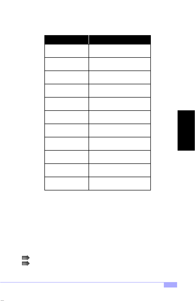
The table below shows how to navigate in the setup program using the keyboard.
Key Function
Arrow keys
Enter
+/-/PGUP/PGDN Change option setting
ESC
F1
F2 Item Help
F5 Previous values
F6 Load failsafe defaults
F7 Load optimized defaults
F9 Menu in BIOS
F10 Save settings and exit
Moves from one selection to the next
Select the highlighted option
Exit
General Help
BIOS
Getting Help
Press [F1] to display a small help win dow that describ es the appropr iate keys to use and the possib le
selections for the highlighted item. To exit the Help Window press [ESC] or the [F1] key aga in.
In Case of Problems
If you discover that you have trouble booting the com puter after making and saving changes with the
BIOS setup program, you can restart the computer by either:
Pressing [CTRL]+[ALT]+[DEL] (all three keys at the same time), or
Holding the power button down until the computer shuts off, then reset the CMOS (see p. 15)
Trinity 450 S2507S
27
Page 28
The best advice is to alte r only sett ings th at you th oroughl y under stand. I n particu lar, do not change settings in the Chipset sc reen unless you are absolutely sure that you need to. The Chipset defaults were
carefully chosen for the best performanc e and r eliability. Even a seem ingly sm all change to the Ch ipset
setup may cause the system to become unstable.
Setup V ariations
Not all systems have the same setup program. While th e basic look and functio n of the setup program
remains more or less the same for all system, the appearance of your Setup screen may differ from other
Award BIOS screens. Each system design an d chipset combination require custom configurations. In
addition, the final appearance of the setup program depends on your system designer. You system
designer can decide tha t certain item s should not be available for use r configurati on, and remove t hem
from the BIOS setup program.
General Help
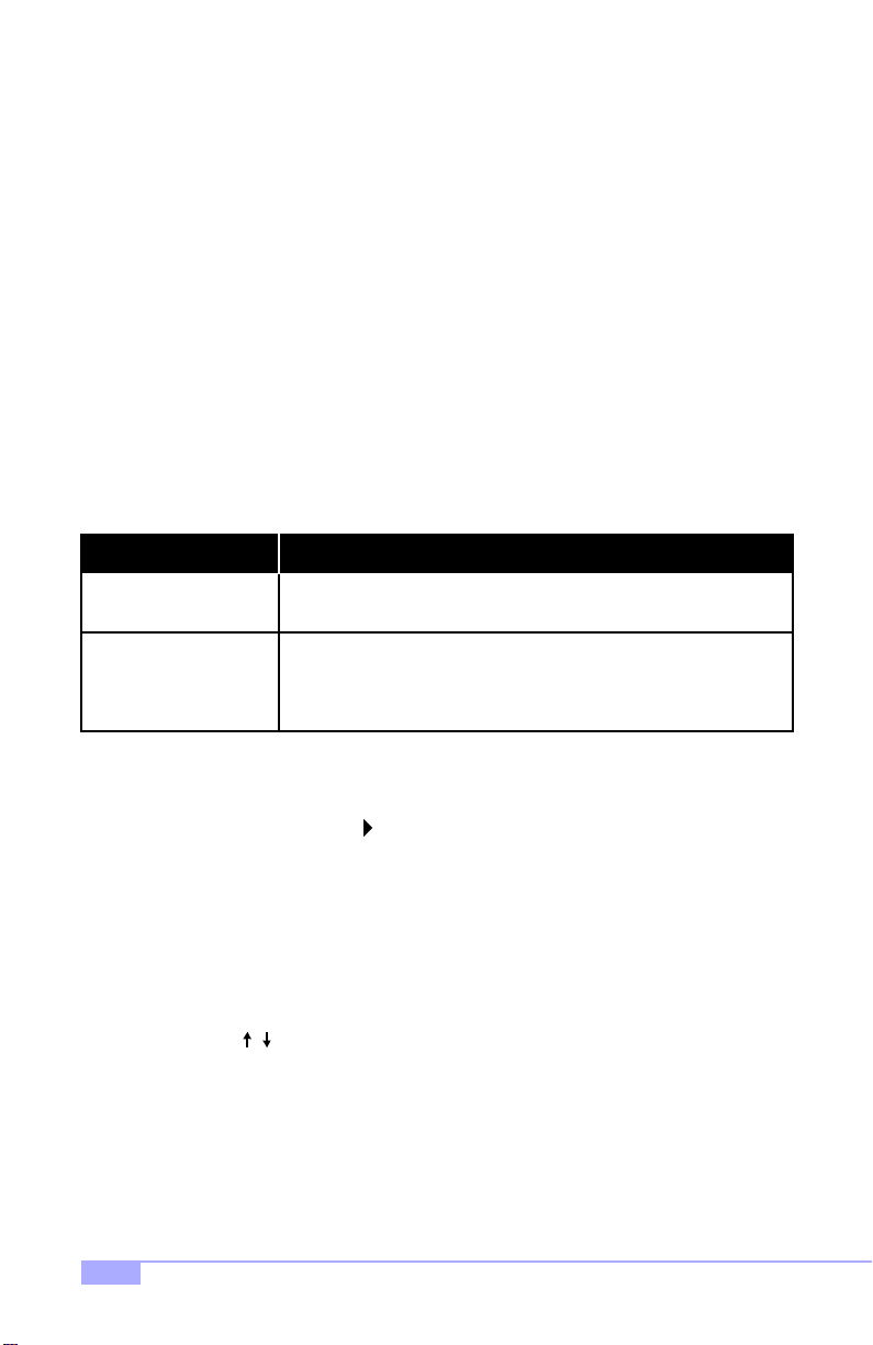
At any time, you can pres s [F1] to bring up a Gen era l Hel p scre en in ca se yo u wa nt to l ea rn the sho rtcu t
commands. There are two settings you should be aware of (listed below).
Setting Function
Load Failsafe Defaults
Load Optimal Defaults
3.1 Main Setup
The BIOS allows you to select from several setup functions and two exit choices. If an additional configuration screen is available, it will have a symbol. If you select that option with that symbol, you will be
brought to another configuration screen. Hitting [ESC] will bring you back out.
3.2 Standar d CMOS Setup
3.2-A. Date/Time
You can type in the date and time directly, or select the portion of the date or time that you want to modify
and adjust it using the cursor keys. The clock runs on a 24-hour cycle (i.e 1:00 PM is 13:00).
3.2-B. IDE Primary/Secondary Master/Slave
These four options are for setting IDE devices such as HDDs and CD-ROMs. If left on the default setting
of “Auto”, the drives will be auto-detected.
The next page describes the settings available for configuring the IDE devices.
If your system is experiencing configuration problems, you can choose
this option to reset all settings.
This will load preset options that are designed for maximum system
performance, but may not work for all computer applications. You
should not use this option if you are experiencing configuration problems.
28
http://www.tyan.com
Page 29
3.2-C. Table of IDE device settings
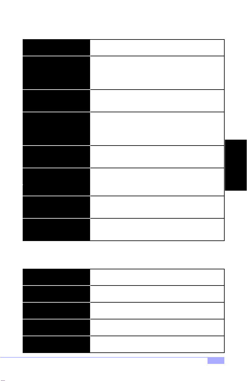
Type
LBA/Large Mode
Block (Multi-sector Transfer)
PIO Mode
DMA Mode
S.M.A.R.T. (Self-Monitoring
Analysis and Repo rt in g Tech-
nology)
32Bit Data Transfer
ARMD Emulation Type
The type of IDE device installed can be configured using this
option. [Default setting is Auto for auto-dete ct]
These modules make it possible for the BIOS to take advantage
of the additional space on drives which are larger than 504MB.
This can be auto-detected (when you select Auto for Type), or
you can manually set this mode to Disabled. [Default setting is
Auto]
When set to Auto, the block mode auto-detects the optimal number of block read/writes per section that the drive supports.
[Default is 0]
Programming input/output is a method of transmitting data
between devices that use the system’s CPU as part of the data
path. There are 6 modes: 5 with their own transmission speed
and 1 auto mode. To use modes 3 and 4, you must use an
Enhanced IDE drive. [Default is Auto]
This option secifies the Direct Memory Access mode for the IDE
device. If set to Auto, the BIOS will determine the DMA mode.
[Default is Auto]
This option allows the S.M.A.R.T. protocol to report server system information over a network. [Default is Auto]
If set to On, this option allows for the transmission of 32-bits in
parallel (e.g. at the same time). If set to Off, only 16-bits will be
transmitted in parallel. [Default is Enabled]
Specifies the type of emulation used for a non-disk device
attached as the primary master IDE device. If set to Auto, the
BIOS will determine the emulation type. [Default is Auto]
BIOS
The following settings are also available in the Standard CMOS Setup screen.
Drive A
Drive B
Floppy 3 Mode
Video
Halt On
The settings are 360KB 5.25”, 1.2MB 5.25”, 720KB 3.5”, 1.44MB
3.5”, or 2.88MB 3.5”.
The options are the same as listed for Floppy A. [Default setting
is Disabled]
Sets whether you have a Japanese standa rd mode floppy
(1.2MB storage on 3.5” drive). [Default is Disabled]
Sets whether or not the drive can be written to. [Default is Dis-
abled]
Sets whether or not the BIOS should check for the drive at
bootup. [Default is Disabled]
Trinity 450 S2507S
29
Page 30
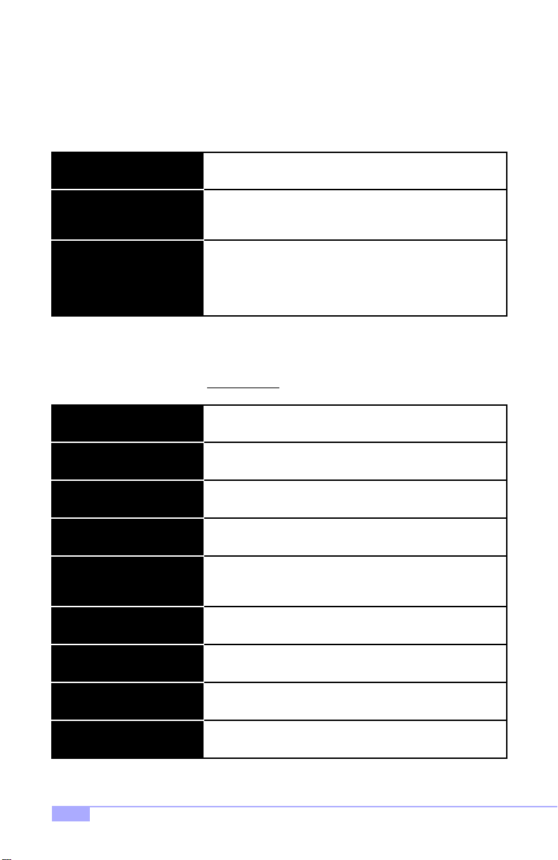
3.2-D. Memory
You cannot change any values in the Memory fields, as they are shown only for your information. The
fields show the total installed random access memory (RAM) and amounts allocated to base, extended,
and other memory. RAM is the computer’s working memory, where the computer stores programs and
data currently being used, so that they are accessible to the CPU. RAM is counted in kilobytes (KB:
approximately one thousand bytes) and megabytes (MB: approximately one million bytes). Modern personal computers may contain up to 128, 256 MB, or more.
Base Memory
Extended memory
Other Memory
3.3 Advanced BIOS Features
This section may allow the user to alter certain settings that affect the way their computer boots up,
checks CPU cache, and other advanced features. Please note that you should not alter settings in
this BIOS section unless you are absolutely sure
Virus Warning
CPU Internal Cache
External Cache
CPU L2 Cache ECC Checking
Quick Power On Self Test
Typically 640KB. Also called conventional memory. The DOS
operating system and conventional applications use this area.
Above the 1MB boundary. Early IBM personal computers could
not use memory above 1MB, but current PCs and their software
can use extended memory.
Between 640KB and 1MB; often called high memory. DOS may
load terminate-and-stay (TSR) programs in this area, such as
device drivers, to free as much conventional memory as possible for applications. Lines in your config.sys file that start with
loadhigh, load programs into high memory, for example.
that you know what you are doing.
Sets whether the BIOS should try to auto-detect for boot viruses,
etc. [Default setting is Disabled]
Sets whether or not your installed CPU has internal cache
[Default setting is Enabled]
Sets whether or not external cache is installed. [Default is
Enabled]
Sets whether the CPU’s L2 (Level 2) cache has ECC checking.
[Default is Enabled]
Sets whether BIOS should perform the quick POST during bootup. [Default is Disabled]
First Boot Device
Second Boot Device
Third Boot Device
Boot Other Device
(continued on next page)
30
Sets the first device that the BIOS should check in order to bootup. [Default is Floppy]
Sets the second device that the BIOS should check in order to
boot-up. [Default is CD-ROM]
Sets the third device that the BIOS should check in order to
boot-up. [Default is HDD-0]
Sets whether still another boot device should be checked.
[Default is Enabled]
http://www.tyan.com
Page 31
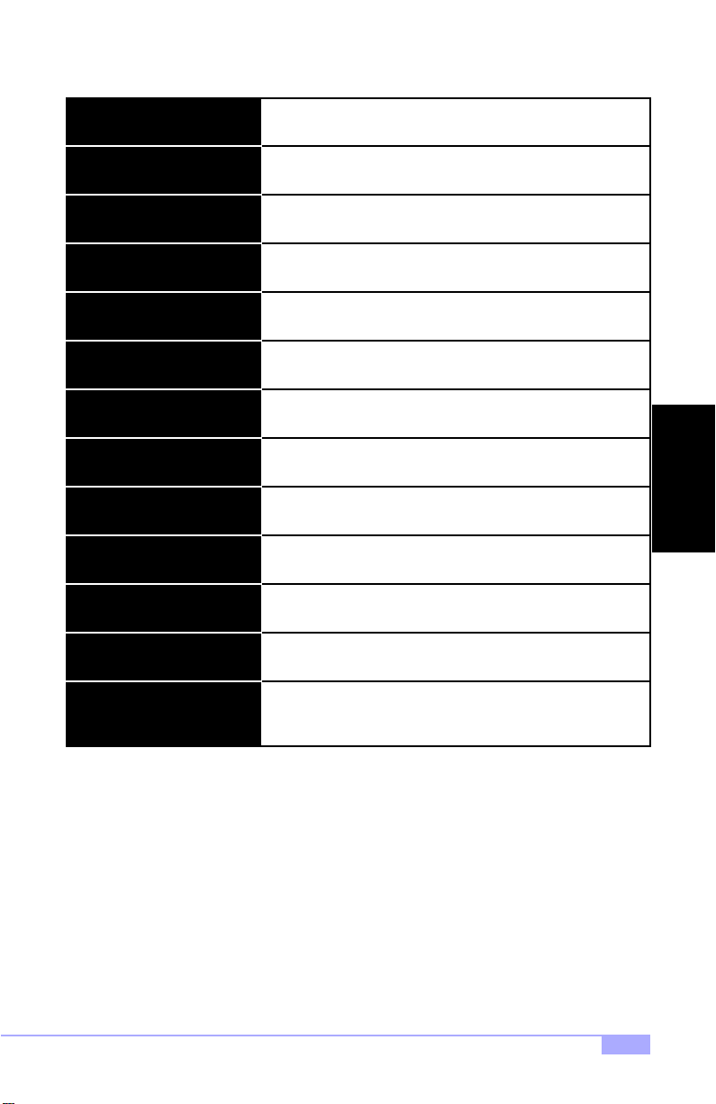
(continued from previous page)
Swap Floppy Dri ve
If you have two drives and need to swap them for some reason,
use this option. [Default setting is Disabled]
Boot Up Floppy Seek
Boot Up Numlock Status
Gate A20 Option
Typematic Rate Setting
Typematic R ate
Typematic Delay
Security Option
PS/2 Mouse Function Control
MPS Version Control for OS
OS Select for DRAM > 64MB
Sets whether the BIOS should check all floppy drives during
boot-up. [Default setting is Enabled]
Sets whether the Num Lock key should be enabled during bootup. [Default is Enabled]
Refers to the method that the system addresses memory above
1MB. [Default is Normal]
Sets whether the keyboard input speed should be altered.
[Default is Disabled]
If above setting is Enabled, this sets the characters per second
of keyboard input. [Default is 6]
If above setting is Enabled, this sets the delay on character input
from keyboard. [Default is 250]
Sets whether the password should be enabled. [Default is
Setup]
Reserved. [Default is Enabled]
Reserved. [Default is 1.1]
If your OS requires this setting, it can be altered from here.
[Default is Non-OS2]
Reserved. [Default is Enabled]Video BIOS Shadow
BIOS
C800-CBFFF Shadow to
DC000-DFFFF Shadow
Trinity 450 S2507S
Reserved. [Default is Enabled]
31
Page 32
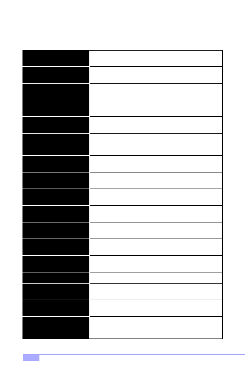
3.4 Advanced Chipset Features
This section describes the settings for the chipset installed on this motherboard. Please note that the
parameters described in this section are for technically competent users only. Do not change
these values unless you completely understand the consequences of your changes.
Bank 0/1 to
Bank 6/7 DRAM Timing
SDRAM Cycle Length
DRAM Drive Strength Reserved. [Default is Auto]
DRAM Drive Value Reserved. [Default is 2F]
Memory Hole
P2C/C2P Concurrency
System Bios Cacheable
Video RAM Cacheabl e
AGP Aperture Size
AGP-4x M ode
AGP Driving Control
Settings depend on type of memory installed, and therefore
these settings are reserved. [Default settings are 5/10ns]
Sets the CAS latency timing. [Default setting is 3]
Specifies the location of an area or memory that cannot be
addressed on the ISA bus. [Default is Disabled]
If Enabled, the PCI/AGP Master to CPU cycle can be concurrent
if the Host CPU is performing R/W access to the PCI or slave
devices. [Default is Enabled]
Sets ability to cache system BIOS ROM at F0000h-FFFFFh.
[Default is Disabled]
Sets whether the video memory should be cacheable. [Default is
Disabled]
The aperture is a portion of the PCI memory address range dedicated for graphics memory address space. [Default is 64M]
Enables the 4X AGP mode (requires a 4X-capable AGP card).
[Default is Enabled]
Some AGP cards require setting this option, otherwise this
option is reserved. [Default is Auto]
AGP Driving Value
CPU to PCI Write Buffer
PCI Dynamic Buffering
(continued on next page)
32
This function is generally reserved for manufacturer use.
[Default is dependent on graphics card]
Setting is dependent on AGP card. [Default is Disabled]AGP Fast Write
Sets whether you have USB devices. [Default is Enabled]OnChip USB
Enable or disable use of a USB keyboard. [Default is Disabled]USB Keyboard Support
Setting this can compensate for speed differences between the
CPU and PCI bus. [Default is Enabled]
If Enabled, every write transaction goes to write buffer. Burstable
transactions then burst on the PCI bus, but non-burstable transactions do not. [Default is Enabled]
http://www.tyan.com
Page 33
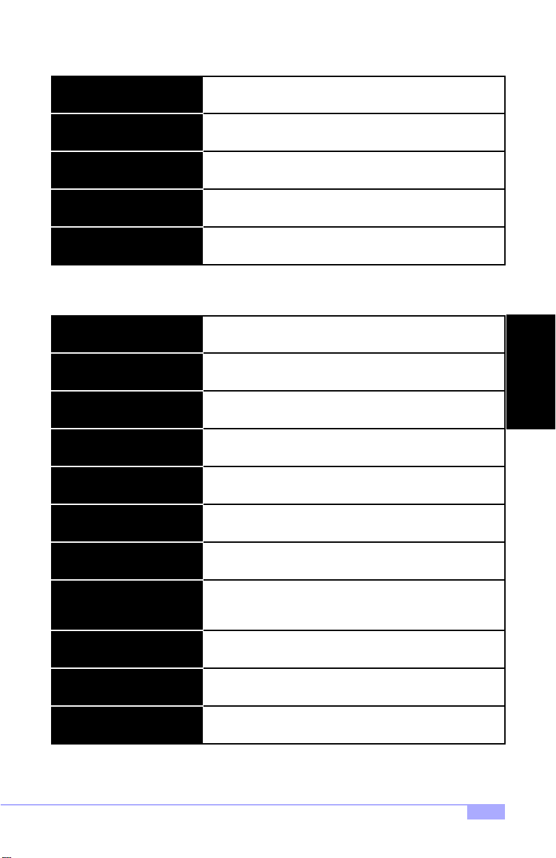
(continued from previous page)
PCI Master 0 WS Write
Sets whether writes to PCI bus are executed with zero wait
states. [Default settings are Enabled]
PCI Delay Transaction
PCI#2 Access #1 Retry
AGP Master 1 WS Write / Read
Memory Parity / ECC Check
3.5 Integrated Peripherals
This section describes settings for the integrated peripherals setup options.
On-Chip IDE Channel 0 / 1
IDE Prefetch Mode
IDE Pri/Sec Master/Slave PIO
IDE Pri/Sec Master/Slave UDMA
Init Display First
IDE HDD Block Mode
Sets write buffer support in compliance with PCi spec v2.1.
[Default setting is Enabled]
Sets whether PCI masters should rotate priority [Default is Dis-
abled]
Sets whether one clock tick should be added to AGP write operations. [Default is Enabled]
Sets whether the BIOS should enable memory checking automatically when it detects ECC DRAM. [Default is Disabled]
Sets the onboard support for the two IDE channels. [Default setting is Enabled]
Sets support for IDE prefetching for faster drive accesses.
[Default setting is Enabled]
Sets PIO mode for each of up to four IDE devices that the
onboard IDE interface supports. [Default is Auto]
Sets whether UDMA data transfer protocol should transfer at
optimal speed, or to auto-detect optimal speed. [Default is Auto]
Sets type of display adapter installed. [Defaul t is PCI Slot]
Sets onboard detection of optimal number of block R/W’s per
sector that the drive can support. [Default is Enabled]
BIOS
Onboard FDD Controller
Onboard Serial Port 1 / 2
UART Mode Selecty
UART2 Duplex Mode
Tx,Rx Inverting Enabled
(continued on next page)
Trinity 450 S2507S
Sets whether onboard floppy controller should be used. [Default
is Enabled]
Sets logical COM port address and corresponding interrupt for
1st and 2nd serial ports. IR is offered on 2nd port. [Default is
Auto]
Sets operating mode for second seria l port. [D efa ult is Stan-
dard]
Sets whether COM port should be able to receive and transmit
data simultaneously. [Default is Half, as in Half-Duplex]
Reserved. [Default is No, Yes]
33
Page 34
(continued from previous page)
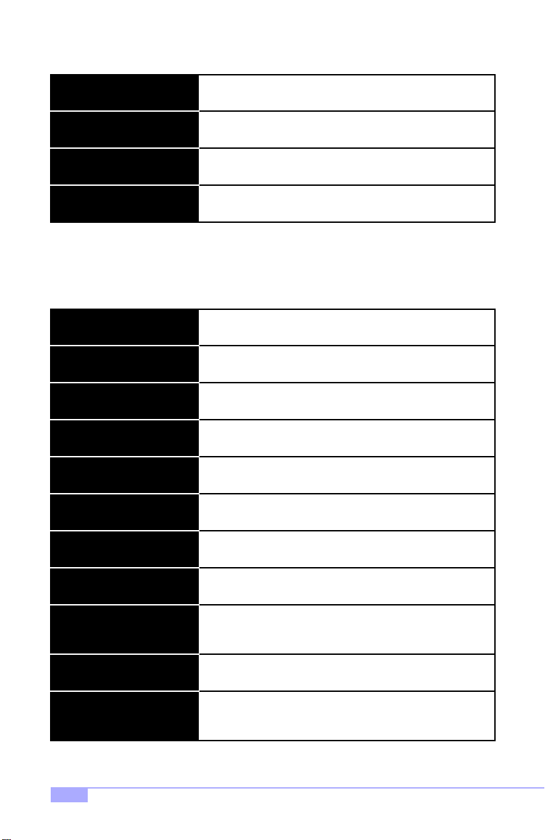
Onboard Parallel Port
Sets logical LPT port address and corresponding interrupt.
[Default setting is 378/IRQ7]
Onboard Parallel Mode
ECP Mode Use DMA
Parallel Port EPP Type
3.6 Power Management Setup
This section describes the different power management functions that may be available on your system.
Please note that power management functions are also dependent on your OS’ power management functions, and that both OS and system power management functions should be set up to work in conjunction
with one another.
ACPI Function
Power Management (subscreen)
Power Management
HDD Power Down
Doze Mode
Suspend Mode
Sets mode for onboard parallel port. [Default setting is Normal]
Sets whether parallel port should use DMA for faster transfer
rate. [Default is 3]
Sets parallel port data transfer mode. [Default is EPP1.9]
Enable or Disable Advanced Configuration Power Interface.
[Default setting is Enabled]
Lets you enter the screen for configuring power states.
Sets whether each mode should be set separately. [Default is
User Define]
Sets time that system should wait before powering down the
HDD(s). [Default is Disable]
Sets time that system should wait before CPU clock runs at
slower speed to save power. [Default is Disabled]
Sets time that system should wait before suspending all devices
except for CPU, to save power. [Default is Disabled]
ACPI Suspend Type
PM Control by APM
Video Off Option
Video Off Method
Modem Use IRQ
(continued on next page)
34
Sets type of suspend function to enable once the system enters
suspend mode. [Default is S1(POS)]
Reserved. [Default is Yes]
Sets power-saving mode for video display. [Default is Suspend-
>Off]
Determines manner in which the monitor is blanked. [Default is
V/H SYNC+Blank]
If Modem Ring Resume is Enabled, it’s possible to wake the
system up by dialing into it. [Default is 3]
http://www.tyan.com
Page 35
(continued from previous page)
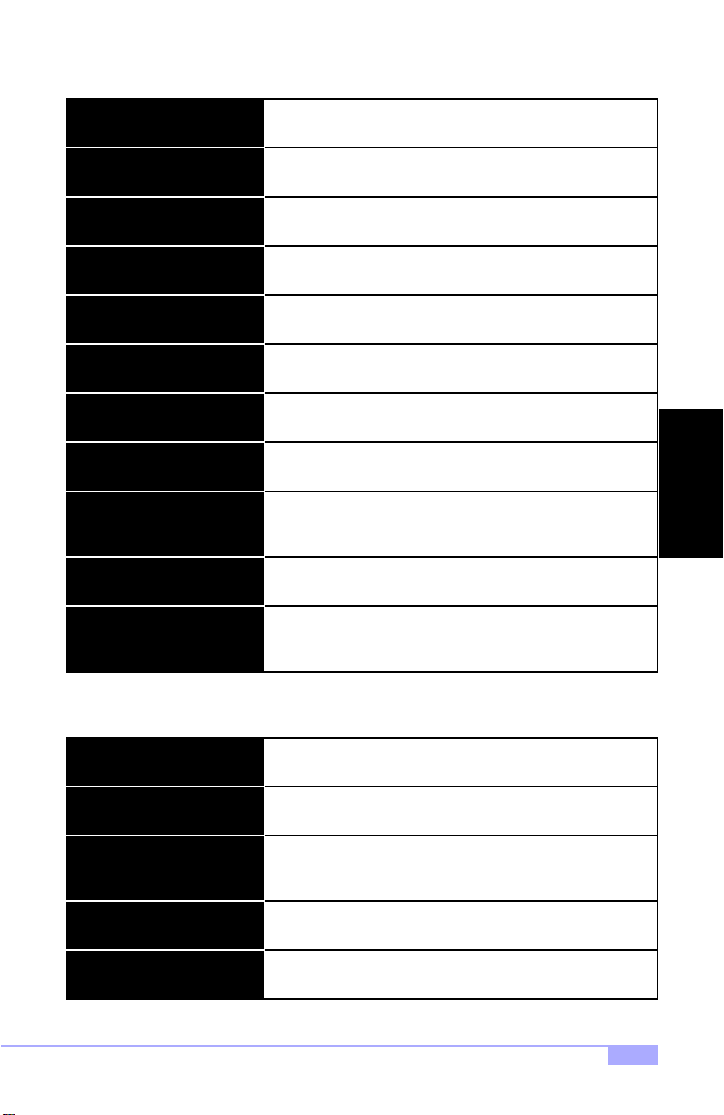
Soft-Off by PWRBTN
Sets time needed to hold down the power button to shutdown
the system. [Default setting is Instant-Off]
Wake Up Events (subscreen)
VGA
LPT & COM
HDD & FDD
PCI Master
Wake Up on LAN / RING
RTC Alarm Resume
Date / Time
Primary INTR
IRQs Activity Monitoring
(subscreen)
3.7 PnP/PCI Configuration
This section describes the PCI/PnP configuration options available.
Lets you enter the screen for configuring wake up events.
Sets video activity as power management event. [Default is Off]
Sets LPT and COM/Serial Port activity as power management
events. [Default is LPT/COM]
Sets floppy and HDD activity as power management events.
[Default is ON]
Sets PCI activity as power management events. [Default is Off]
Sets Wake Up on LAN / Ring as power management events.
[Default is Disabled]
Sets RTC Alarm as a power management event. [Default is Dis-
abled]
Sets Date and Time that system will wake up. [Default is 0]
Sets whether IRQ activity should be a power mana gem en t
event. [Default is ON]
In this screen, you can assign how power management will
monitor each IRQ.
BIOS
PNP OS Installed
Reset Configuration Data
Resources Controlled By
(ESCD)
IRQ Resour ces
DMA Resources
(continued on next page)
Trinity 450 S2507S
Sets whether the system is using a Plug-n-Play OS. [Default setting is NO]
Sets whether the configuration data in the ESCD should be
reset at bootup. [Default setting is Disabled]
Sets how the PnP devices will be controlled. [Defa ult is
Auto(ESCD)]
Sets IRQs PnP control statuses.
Sets DMAs PnP control statuses.
35
Page 36
(continued from previous page)
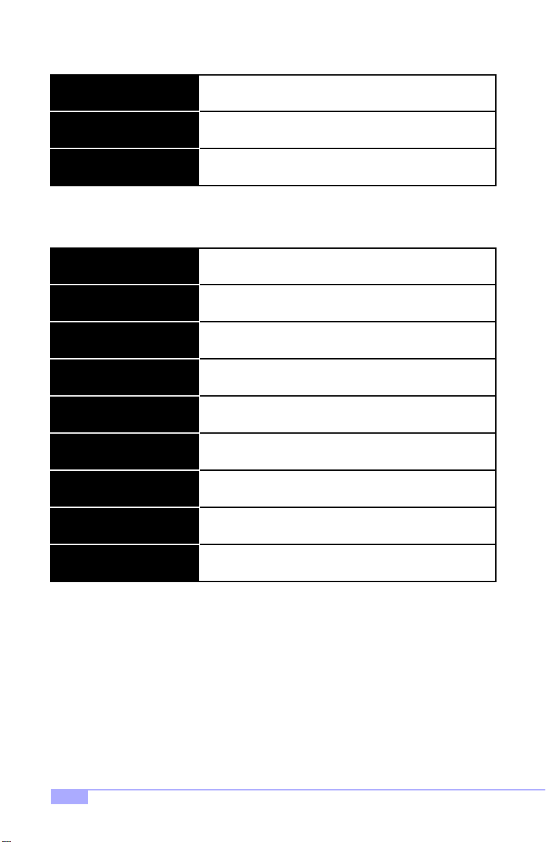
PCI/VGA Palette Snoop
Reserved. [Default setting is Disabled]
Assign IRQ for VGA
Assign IRQ for USB
3.8 PC Health Status
This section describes the hardware monitoring of certain onboard devices. No options are user-defined.
Current CPU1 Temp. Displays temperature of CPU1 in Celsisus and Farenheit.
Current CPU2 Temp.
Current CPUFAN1 Speed
Current CPUFAN2 Speed
CPU1 Vcore
CPU2 Vcore
3.3V
Sets whether an IRQ should be reserved for VGA. [Default setting is Enabled]
Sets whether an IRQ should be reserved for USB. [Default setting is Enabled]
Displays temperature of CPU2 in Celsisus and Farenheit.
Displays speed of CPUFAN1 in revolutions per minute (RPM).
Displays speed of CPUFAN2 in revolutions per minute (RPM).
Displays core voltage of CPU1.
Displays core voltage of CPU2.
Displays power supply voltage on 3.3V line.
Displays power supply voltage on 5V line.5V
12V
3.9 Set Supervisor Password / Set User Password
Both of these functions allow for passwords to be set accordingly for BIOS configuration.
When selecting one of the password functions, the following words will appear:
After typing in a new password of up to eight characters, press [Enter]. The following words will then
appear:
Type your new password again, and the password will then be set. Please note that entering a new password and then confirming it, will clear any old password that you had (depending on type of password).
36
Displays power supply voltage on 12V line.
ENTER PASSWORD:
CONFIRM PASSWO RD:
http://www.tyan.com
Page 37
3.10 Flash Utility
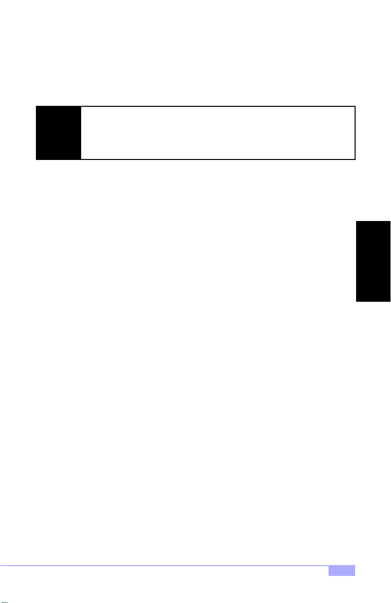
NOTE: You will need to visit the Tyan website at http://www.tyan.com if you would like to get the Flash
Utility, as well as any BIOS updates for your motherboard. Updates and more information about flashing
the BIOS are available from the Tyan website.
Instructions on flashing the BIOS are available from the Tyan website at http://www.tyan.com
Please be aware that by flash ing your BIOS, you a gree that in the eve nt of a BIOS
NOTE:
flash failure, you must contact your dealer fo r a replacement BIOS. T here are no
exceptions. Tyan does not have a policy of replacing B IOS chips directly with end
users. In no event will Tyan be held responsible for damage done to the BIOS by the
end user.
BIOS
Trinity 450 S2507S
37
Page 38

Chapter 4: System Resources
Note: If you experience problems with setting up your system, always check the following things in the
following order:
CPU, MEMORY, VIDEO
By checking these items, you will most likely find out what the problem might have been when setting up
your system. For more info rmation on troubleshooting, check the Tyan website a t http://www.tyan.com
4.1 Beep Codes
Fatal errors, which halt the boot process, are communicated through a series or audible beeps. For example, if the Award BIOS POST can initialize the video but an error occurs, an error message will be displayed. If it cannot display video, it will convey a series of beeps.
If you hear one long beep followed by two short beeps, then a video problem has probably occured and
the BIOS is having difficulty initializing the video display. Any other beep sequences that may or may not
occur are probably due to memory problems.
4.2 Displayed Error Messages
If an error occurs after the system display has been initialized, an error message will be displayed as follows:
ERROR Message Line 1
ERROR Message Line 2
Press <F1> to continue
and the system will halt. Depending on how the Halt On setting was configured in the Standard CMOS
Setup menu, the system may or may not display the error message.
RUN SETUP UTILITY
may also appear. Press [F1] to run the Award BIOS Setup if this message appears. The following two
pages show the possible error messages and explanations.
38
http://www.tyan.com
Page 39
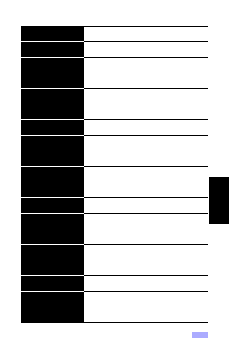
8042 Gate-A20 Error Gate A20 on the keyboard controller (8042) is not working.
Address Line Short!
C: Drive Error No response from drive C:
C: Drive Failure No response from drive C:
Cache Memory Bad, Do Not
Enable Cache!
CH-2 Timer Error Timer 2 has failed.
CMOS Battery State Low The battery is running low and needs to be replaced.
CMOS Checksum Failure
CMOS System Options Not Set
CMOS Display Type Mismatch
CMOS Memory Size Mismatch
CMOS Time and Date Not Set
Error in the address decoding circuitry.
Cache memory is defective.
The CMOS data is different than previous data. Run BIOS setup
to enter new data.
CMOS RAM values were destroyed. Run BIOS setup to enter
new data.
Video type set in BIOS does not match actual video display. Run
BIOS setup to enter new data.
Memory size does not match actual detected memory size. Run
BIOS setup to enter new data.
Time and Date have not been set. Run BIOS setup to enter new
data.
SYSTEM
Display Switch Not Proper
Trinity 450 S2507S
No response from drive D:D: Drive Error
No response from drive D:D: Drive Failure
Diskette cannot be used to boot system.Diskette Boot Failure
Some systems require a video switch to be set to either color or
monochrome. Power down the system and set the switch.
Error in the DMA controller.DMA Error
Error in the first DMA channel.DMA 1 Error
Error in the second DMA channel.DMA 2 Error
39
Page 40
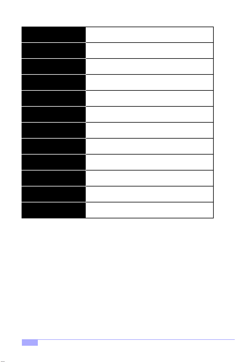
FDD Controller Failure FDD controller is not responding .
HDD Controller Failure
INTR1 Error Interrupt channel 1 failed POST.
INTR2 Error Interrupt channel 2 failed POST.
Invalid Boot Diskette Diskette is not bootable.
Keyboard is Locked... Unlock it Keyboard lock is engaged. Power down and unlock it.
Keyboard Error Keyboard appears to have a timing problem.
KB/Interface Error
No ROM BASIC
Parity Error ???
HDD controller is not responding.
Error in keyboard connection.
System cannot find a bootable sector on any boot drive.
Parity error in external memory.Off Board Parity Error
Parity error in internal memory.On Board Parity Error
Parity error at unknown address.
40
http://www.tyan.com
Page 41
Appendix I: Glossary
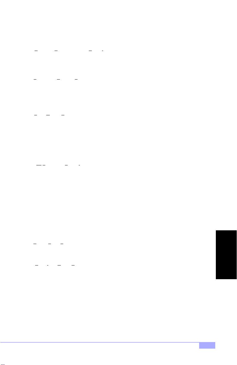
ACPI (Advanced Configuration an d Power Interface): a pow er m anage ment s pecific ation th at al lows the
operating system to control the amount of power distributed to the computer’s devices. Devices not in use
can be turned off, reducing unnecessary power expenditure.
AGP (A
ccelerated Graphics Port): a PCI-base d inte rfa ce whic h was de sign ed spe ci fical ly for dem and s of
3D graphics applications. Th e 32-bi t AGP chann el directl y links the grap hics con troller to the main memory. While the channel runs at only 66 MHz, it supports data transmission during both the rising and falling
ends of the clock cycle, yielding an effective speed of 133 MHz.
AMR (A
udio Modem Riser) : a mod em tha t can b e used on Intel Refe rence Mothe rboard platfor ms using
Intel’s core logic chipsets supporting AC-link 2.1. It supports fax and all data feedback modes. It provides
high speed communicati o ns be twee n you r p erso na l comp ute r an d a rem ote locat i on, s uch a s an Internet
Service Provider (ISP).
AT: the original form factor of IBM’s PC.
ATAPI (AT
the disk controller on the dev ice itsel f. It all ows CD -ROMs an d tape dr ives to be co nfigure d as maste r or
slave devices, just like HDDs.
ATX: the form factor designed to repl ace the AT form factor. It improves on the AT design by rotating the
board 90 degrees, so tha t the IDE connecto rs are close r to the drive b ays, and the CPU is closer to the
power supply and cooling fan. The keyboard, mouse, USB, serial, and parallel ports are built-in.
Bandwidth: refers to carrying cap aci ty. The greater the ban dw idt h, th e m ore dat a the bus, phone line, or
other electrical path, can carry. Greater bandwidth, then, also results in greater speed.
BBS (B
center for users to post messages and access information.
BIOS (B
instructions for controlling your computer’s hardware. Both the operating system and application software
use BIOS routines to ensure compatibility.
Buffer: a portion of RAM which is u sed to te mp ora ril y sto re d ata , usu all y fr om an a pplic a tion , tho ugh i t is
also used when printing, and in most keyboard dr ivers. The CPU can manipulat e data in a buffer before
copying it, all at once, to a disk drive. While this improves syst em performance --- readin g to or writing
from a disk drive a single time is much fa ster than doing so repeatedly --- there is also the possi bility of
losing your data should the system cr ash. Inf ormatio n sto re d in a bu ffer is te mp orarily st ore d, n ot p ermanently saved.
Attachment Packet Interface): also known as IDE or ATA; a drive implementation that includes
ulletin Board System): a computer system with a number of modems hooked up to it which acts a
asic Input/Output System): the program that resides in the ROM chip, an d provides the basic
GLOSSARY
Trinity 450 S2507S
41
Page 42

Bus: a data pathway. The term is used especially t o refer to the connec tion bet ween the pr ocessor and
system memory, and between the processor and PCI or ISA local buses.
Bus mastering: allows peripheral devices and IDEs to access the system memory without going through
the CPU (similar to DMA channels).
Cache: a temporary storage area for data that will be needed often by an application. Using a cache lowers data access times, since th e ne ed ed i n for mat ion is stored in the SRAM instea d o f in the sl ow DR AM .
Note that the cache is also mu ch sm al le r th an your re gu lar m em or y: a typi ca l cach e size i s 51 2KB , wh ile
you may have as much as 1GB of regular memory.
Cache size: refers to the physical size of the cache onboard. This should not be confused with the cacheable area, which is the total amoun t of m emory wh ich ca n be sc anned by the syste m in se arch of da ta to
put into the cache. A ty pical setup would b e a ca che si ze o f 512KB , an d a ca cheable area of 5 12MB. In
this case, up to 512KB of the main memory onboard is capable of being cached. However, only 512KB of
this memory will be in the cache at any given moment. Any main memory above 512MB could never be
cached.
Closed and open jumpers: jumpers and jumper pins are active when they are “on” or “closed”, and inactive when they are “off” or “open”.
CMOS (C
the BIOS.
COM port: another name fo r t he seri a l po rt, whi ch is ca l led as su ch beca use i t tr an smits the eig ht b i ts o f
a byte of data along one w ire , an d re cei ve s da ta on another single w ire ( tha t i s, th e da ta is t ran smit ted in
serial form, one bit after another) . Parallel ports tran smit the bits of a byte on eight different w ires at the
same time (that is, in parallel form, eight bits at the same time).
DDR (D
and falling edge of the system clock rather than on just the rising edge, potentially doubling output.
DIMM (D
need to be installed in pairs.
DIMM bank: sometim es called DIMM sockets, because the physical slot and th e logical unit are the
same. That is, one DIMM module fits into one DI MM socket, which is capable o f acting as a memory
bank.
DMA (D
(like soundcards or keyboards) to access the main memory without involving the CPU. This frees up CPU
resources for other tasks. As with IRQs, it is vital that you do not double up devices on a single line. Plugn-Play devices will take care of this for you.
omplementary Metal-Oxide Semiconductors): chips that hold the basic startup information for
ouble Data Rate): improves RAM speed to at least 200 MHz. It activates output on both the rising
ual In-line Memory Modul e): faster and m ore capacious form of R AM than SIMM s, and do not
irect Memory Access): channels that are similar to IRQs. DMA chann els allow hardware devices
42
http://www.tyan.com
Page 43
Doze mode: in this mode, only the CPU’s speed is slowed.
DRAM (D
dency to lose data if it is not recharged regularly (every few milliseconds). This refresh requirement
makes DRAM three to ten times slower than non-recharged RAM such as SRAM.
EDO RAM (E
addresses are static; the next time it looks for a bit of data, it will be at the same spot, or one nearby.
EEPROM (E
unlike normal ROM, be upd ated. T his allow s you to keep up with ch anges in th e BIOS pro gram s withou t
having to buy a new chip. Tyan’s BIOS updates can be found at http://www.tyan.com
ESCD (E
in the system BIOS. This information helps properly configure the system each time it boots.
Fault-tolerance: a term describin g a sy stem w her e one com pon ent can qu ick ly be re plac ed w itho ut ca using a loss of service, such as in a RAID system.
Firmware: low-level software that controls the system hardware.
Form factor: an i nd ust ry t erm fo r the size, sh ape , p ow er su ppl y typ e, a nd ext ern al c onn ecto r type of the
Personal Computer Board (PCB) or motherboard. The standard form factors are the AT and ATX,
although Tyan also makes some Baby-AT and ATX Footprint boards.
Global timer: onboard hardware timer, such as the Real-Time Clock (RTC).
ynamic RAM): widely a vailable, very affordable for m of RAM which has t he unfortunate ten-
xtended Data-Out RAM ): speeds access to memory loca tions by assuming that memor y
lectrically Erasable Programmable ROM): also called Flash BIOS, is a ROM chip which can,
xtended System Configuration Data): a format fo r stori ng infor ma tion a bou t P lug- n-Pl a y device s
Handshaking: a form of encryption. One system, typically the server, sends an encryption sc heme to
another agent, typically a client. Thus, the client’s data is protected during transmittal to the server.
HDD: stands for H
H-SYNC: controls the horizontal synchronization/properties of the monitor.
ntegrate d Circuit): the formal name for the computer chip.
IC (I
ntegrated Device/Drive Electronics): a simple, self-contained HDD interface. It can handle drives up
IDE (I
to 8.4 GB in size. Almost all IDE s sold now are in fact Enhanced IDEs (EIDEs), with maximum capa city
determined by the hardware controller.
IDE INT (IDE Interrupt): a hardware interrupt signal that goes to the IDE.
Trinity 450 S2507S
ard Disk Drive, a type of fixed drive.
43
GLOSSARY
Page 44

I/O (Input/Output): the connection between your computer and another piece of hardware (mouse, key-
board, etc.)
IRQ (Interrupt Request): an electronic request that runs from a hardware device to the CPU. The interrupt
controller assigns priorities to incoming requests and delivers them to the CPU. It is important that there is
only one device hooked up t o each IRQ line; d oubling u p devices o n IRQ lin es can lock u p your sys tem.
Plug-n-Play operating systems can take care of these details for you.
ISA (I
ndustry Standard Architecture): a slower 8- or 16-bit bus (data pathway).
Latency: the amount of time that one part of a system spends waiting for another part to catch up. This is
most common when the syste m s end s da ta o ut t o a per iphe ra l device, and it waiting for th e p erip her al to
send some data back (peripherals tend to be slower than onboard system components).
Mirroring: see RAID.
NVRAM: ROM and EEPROM are both examples of Non-Volatile RAM, memory that holds its data without
power. DRAM, in contrast, is volatile.
OEMs (O
and hardware inside their case and sell them.
Parallel port: transmits the bits of a byte on eight different wires at the same time (that is, in parallel form,
eight bits at the same time).
PCI (P
bus. Local buses are those which operate within a single system (as opposed to a ne twork bus, which
connects multiple systems).
PCI PIO (PCI P
modes use the C PU for dat a transfer ( in contrast, D MA channel s do not). PCI refers to the type of bus
used by these modes to communicate with the CPU.
PCI-to-PCI bridge: allows you to connect multiple PCI devices onto one PCI slot.
Pipeline burst SRAM: a fast secondary cache. It is used as a secondary cache because SRAM is slower
than SDRAM, but usually large r. Data is cached first to the fa ster prim ary cache, and then, when the pr imary cache is full, to the slower secondary cache.
Pipelining: improves system perform ance by allowing the CPU to begin exe cuting a second instru ction
before the first i s com pleted. A pipeline can be l ike ned to an assembly li ne , with a given part of th e p i peline repeatedly executing a set part of an operation on a series of instructions.
riginal Equipm ent Manufacturers): Compaq or IBM package other companies’ mother boards
eripheral Comp onent Int erconn ect): a 32-b it loc al bus ( data pathw ay) wh ich is faster than the IS A
rogrammable Input/Output) modes: the da ta transfer modes used by IDE drives. These
44
http://www.tyan.com
Page 45
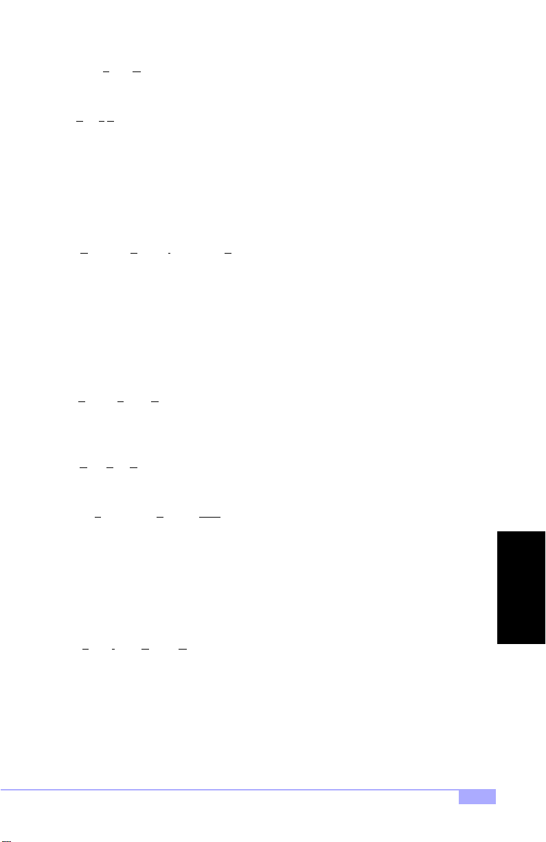
PM timers (Pow e r M ana gem en t time rs) : software timers that count down the number of seconds or minutes until the system times out and enters sleep, suspend, or doze mode.
PnP (P
lug-n-Play): a design standard that has become ascendant in the industry. Plug-n-Play devices
require little set-up to use. Novice end use rs can simply plu g them into a compu ter that is run ning on a
Plug-n-Play aware operatin g system ( such as Win dows 98), and go to wo rk. Devices a nd oper ating systems that are not Plug-n-Play require you to reconfigu re your system each time you ad d or change any
part of your hardware.
Striping: see RAID.
RAID (R
edundant Array of Independ ent Disks): a way for the same dat a to be stor ed in different places
on many hard drives. B y using this m ethod, the data is sto red redundan tly, also the multiple hard drives
willl appear as a single drive to the operating system. RAID level 0 is is known as striping, where data is
striped (or overlapped) across multiple hard drives, but offers no fault-tolerance. RAID level 1 is known as
mirroring, which stores th e data within at least two hard dr ives, but does not stripe. RAID level 1 also
allows for faster access time and fault-toleranc e, since either hard dr ive can be read at the s ame time.
RAID level 0+1 is both str iping and mir roring, providing fault-toler ance, striping, an d faster access all at
the same time.
RAM (R
andom Access Memory): technically refers to a type of memory where any byte can be accessed
without touching the adjacent data, is ofte n used to refer to the system’s main memory. This memory is
available to any program running on the computer.
ROM (R
ead-Only Memory): a storage chip wh ich contains the BIOS ; the basic instructions req uired to
boot the computer and start up the operating system.
SDRAM (S
addresses open simultaneo usly. By transferring data alternat ely from one set of ad dresses and th en the
other, SDRAM cuts down on the delays associated with non -synchronous RAM, which mus t close one
address bank before opening the next.
Serial port: called as such because it tran smits the eight bits of a byte of data along one wire, and
receives data on another single wire (that is, the data is transmitted in serial form, one bit after another).
SIMM (S
must be installed in pairs, and do not have the carrying capacity or the speed of DIMMs.
SIMM bank/socket : SIMM s ockets are the physical slots into which you install SIM M modules. A pair o f
SIMM sockets form a SIMM bank, and act as one unit. If only one socket is filled, the bank will not op erate.
Sleep/Suspend mode: in this mode, all devices except the CPU shut down.
Trinity 450 S2507S
ynchronous Dynamic RAM): called as such because it can keep two sets of memory
ingle In-line Memory Module): formerly the most common form of RAM f or motherboa rds. They
45
GLOSSARY
Page 46

SRAM (Static RAM): unlike DRAM, thi s type of RAM doe s not need to be refreshed in o rder to preven t
data loss. Thus, it is faster, and more expensive.
Standby mode: in this mode, the video and fixed disk drive (usually the HDD) shuts down; all other
devices continue to operate normally.
UltraDMA/33/66/100: a fast version of the old DMA channel. UltraDMA is also called UltraATA. Without
the proper UltraDMA controller, your system cannot take advantage of the higher data transmission rates
of the new UltraDMA/UltraATA HDDs.
USB (U
niversal Serial Bus): a ver satile port. T his one po rt type ca n functi on as a serial, pa ral lel, mouse ,
keyboard, or joystick port. It is fas t enough to supp ort video transfer, and is capable of supp orting up to
127 daisy-chained peripheral devices.
VGA (V
ideo Graphics Array): the PC video display standard.
V-SYNC: controls the vertical properties of the monitor.
ZIF socket (Z
ing the sensitive CPU pins. The CPU is lightly placed in an open ZIF socket, and the metal level is pulled
down. This shifts the processor over and down, guiding it into place on the board.
ero Insertion Force socke t): these sockets make it poss ible to inse rt CPUs wit hout damag-
46
http://www.tyan.com
Page 47
Notice for the USA
Compliance Information Statement (Declaration of Conformity Procedure) DoC
FCC Part 15: This device complies with Part 15 of the FCC Rules.
Operation is subject to the following cond itions:
1)
this device may not cause harmful interference, and
2)
this device must accept any interference received including
interference that may cause undesired operation. If this
equipment does cause harmful interference to radio or television reception, which can be determined by turning the equiipment off and on, the user is encouraged to try one or more
of the following measures:
Reorient or relocate the receivin g
antenna.
Increase the separation between the
equipment and receiver.
Plug the equipment into an outlet on
a circuit different from that of the
receiver.
Consult the dealer or an experienced
radio/television technician for help.
Notice for Canada
This apparatus complies with the Class B limits for radio interference as specified in the Canadian Department of Communicat ions Radio Interference Regulations . (Cet appareil est conforme aux norm es de
Classe B d’interference ra dio tel que spécifié par le Mini stére Candien des Communicati ons dans les
réglements d’inteférence radio.)
Notice for Europe (CE Mar k)
This product is in conformity with the Council Directive 89/336/EEC, 92/31/EEC (EMC).
CAUTION: Lithium battery i ncluded with t his board. Do no t puncture, multi late, or dispose of battery in
fire. Danger of explos ion if ba ttery is incorr ectly repla ced. R eplace only wit h the sa me or e quivalen t type
recommended by ma nufacturer. Dispose of used batter y according to man ufacturer instructions a nd in
accordance with your local regulations.
Trinity 450 S2507S
Document # D1440-100
47
 Loading...