

Page 1

S2707
Trinity GC-SL
///
Revision 1.02
Copyright © TYAN Computer Corporation, 2001- 2002. All rights reserved. No part of this manual
may be reproduced or translated without prior written consent from TYAN Computer Corp.
All registered and unregistered trademarks and ompany names contained in this manual are
property of the r respective owners including, but not limited to the following.
TYAN, Trinity GC- SL S2707 are trademarks of TYAN Computer Corporation.
Intel, Pentium, and combinations thereof are trademarks of Intel Corporation.
Adaptec is a trademark of Adaptec, Incorporated.
AMI, AMIBIOS are trademarks of American Megatrends, Incorporated.
Microsoft, Windows are trademarks of Microsoft Corporation.
National is a trademark of National Semiconductor.
Promise is a trademark of Promise Technology.
IBM, PC, AT, and PS/2 are trademarks of IBM Corporation.
Winbond is a trademark of Winbond Electronics Corporation.
Portable Document Format (PDF) is a trademark of Adobe Corporation.
Information contained in this document is furnished by TYAN Computer Corporation and has been
reviewed for accuracy and reliability prior to printing. TYAN assumes no liability whatsoever, and
disclaims any express or implied warranty, relating to sale and/or use of TYA N products including
liability or warranties relating to fitness for a particular purpose or merchantability. TYAN retains the
right to make changes to product descriptions and/or specifications at any time, without notice. In
no event will TYAN be held liable for any direct or indirect, incidental or consequential damage,
loss of use, loss of data or other malady resulting from errors or inaccuracies of information
contained in this document.
1
http://www.TYAN.com
Page 2

Table of Contents
Before you begin…
Chapter 1: Introduction
1.0 Congratulations!
1.1 Hardware Specifications
Chapter 2: Board Installation
2.0 Board Image
2.1 Board Parts
2.2 Jumper Settings
2.3 Connectors
2.4 Front Panel Connector (J22)
2.5 Clear CMOS (JP1)
2.6 64- bit PCI Slot Selection (JP9)
2.7 Intel 82545EM Gigabit NIC (JP22)
2.8 Onboard Intel 82545EM LAN
LED Header (J38)
2.9 Intel 82551QM/82540EM NIC (JP24)
2.10 Onboard Intel 82551QM/82540EM
LAN LED Header (J40)
2.11 Onboard ATI RAGE XL Graphics
2.12 Onboard SCSI
2.13 Promise RAID IDE Controller
2.14 Chassis Intrusion Header (J22)
2.15 CPU Thermal Trip (J23)
2.16 Watchdog Timer Control (JP38)
2.17 Fan Connectors
2.18 Serial Header (COM2)
2.19 USB Header (J30)
2.20 Mounting the Motherboard
2.21 Installing the Memory
2.22 Installing the Processor & Heatsink
2.23 Attaching Drive Cables
2.24 Installing Add- In Cards
2.25 Connecting External Devices
2.26 Installing the Power Supply
2.27 Finishing Up
Chapter 3: BIOS
3.0 Main BIOS Setup
3.1 Advanced Settings
3.2 Chipset
3.3 PCI Pnp
3.4 Power
3.5 Boot
3.6 Security
3.7 Exit
Chapter 4: Diagnostics
4.0 Beep Codes
4.1 Flash Utility
Appendix: Glossary
Technical Support
……………………………………………..Page 3
……………………………………………..Page 4
……………………………………………..Page 4
……………………………………………..Page 4
……………………………………………..Pa ge 6
……………………………………………..Page 7
……………………………………………..Page 8
……………………………………………..Page 9
……………………………………………..Page 9
……………………………………………Page 10
……………………………………………Page 11
……………………………………………Page 11
……………………………………………Page 12
……………………………………………Page 13
……………………………………………Page 13
……………………………………………Page 13
……………………………………………Page 14
……………………………………………Page 14
……………………………………………Page 14
……………………………………………Page 14
……………………………………………Page 15
……………………………………………Page 15
……………………………………………Page 15
……………………………………………Page 16
……………………………………………Page 16
……………………………………………Page 17
……………………………………………Page 18
……………………………………………Page 20
……………………………………………Page 22
……………………………………………Page 24
……………………………………………Page 25
……………………………………………Page 26
……………………………………………Page 27
……………………………………………Page 28
……………………………………………Page 30
……………………………………………Page 30
……………………………………………Page 31
……………………………………………Page 31
……………………………………………Page 32
……………………………………………Page 32
……………………………………………Page 32
……………………………………………Page 32
……………………………………………Page 33
……………………………………………Page 33
……………………………………………Page 33
……………………………………………Page 34
……………………………………………Page 39
2
http://www.TYAN.com
Page 3

Before you begin…
Check the box contents!
The retail motherboard package should contain the following:
1x Trinity GC-SL motherboard
1x CPU retention
1x 34-Pin floppy drive cable
1x LVD SCSI cable (if optional SCSI included)
1 x Ultra- DMA-133/100/66/33 IDE cable (2 cables , if optional RAID included)
1x Cable set: 9- pin Serial
1x Trinity GC-SL User’s Manual
1x Trinity GC-SL Quick Reference guide
1x TYAN driver CD
1x Adaptec SCSI driver diskette (if optional SCSI included)
1x Promise RAID driver diskette (if optional RAID included)
1x I/O shield
If any of these items are missing, please contact your vendor/dealer for replacement before
continuing with the installation process.
3
http://www.TYAN.com
Page 4

Chapter 1: Introduction
1.0 – Congratulations!
You are now the owner of one of the most flexible mPGA478-based motherboards available.
Utilizing the latest chipset technology for Pentium 4 server and workstation-class computing, the
Trinity GC-SL is designed to handle even the most demanding software applications.
Networking? Transferring large volumes of data? Distributed computing? Load balancing? The
Trinity GC-SL has you covered. There are dual onboard LAN ports, including one Gigabit Ethernet
port and one Fast Ethernet port, allowing you a flexible working environment.
The Trinity GC- SL is designed to fit a variety of applications, including the space-restricted 1U/2U
chassis and pedestals.
Remember to visit Tyan’s web site at http://www.tyan.com. There you can find information on all of
Tyan’s products with FAQs, a complete distributors list, and BIOS setting explanations.
1.1 – Hardware Specifications
Processor
• ZIF mPGA478 socket
• Supports the Intel Pentium 4 processor
• Supports 400MHz/533 MHz
Front- Side Bus (FSB)
• Supports Celeron mPGA478
• Onboard VRM 9.0
Chipset
• ServerWorks GC-SL chipset
• CMIC-SL, CIOB-X 2.0, CSB5
• National PC87417 Super I/O
• Winbond W83782D Hardware Monitor
Memory
• Four DDR DIMM sockets (minimum one
DIMM)
• Supports up to 4GB
• Supports Registered ECC DDR (72-bit)
memory modules only
Integrated PCI IDE
• Dual-channel PCI bus-master mode
• Supports up to four Enhanced IDE devices
• Supports for ATA-100/66/33 IDE and ATAPI
compliant devices
Integrated Video (Manufacturing option)
• ATI RAGE XL graphics controller
• 8MB frame buffer (SDRAM)
• Standard 15-pin analog VGA port
Integrated SCSI (Manufacturing option)
• Adaptec AIC-7892X/7901 Ultra160/320 Single
Channel SCSI Controller
• Operating at PCI 66MHz Bus
• Supports Intel’s RAIDIOS RAID solution
• Supports the Adaptec’s 2000S Zero- Channel
RAID though one of the PCI 66MHz slots
• 68-pin SCSI connector
Integrated LAN Controller(s)
• One 64-bit PCI- X Gigabit NIC
• Intel 82545EM 10/100/1000 Ethernet Chip
• Operating at 100/66MHz bus
• One 32-bit/33MHz PCI Ethernet NIC
• Intel 82551QM 10/100Mbit LAN controller
or Intel 82540EM(Manufacturing option)
Gigabit Ethernet NIC
Integrated IDE (ATA) RAID
(Manufacturing option)
• Promise PDC20276 IDE controller
• Dual- channel PCI bus-master mode
• Supports up to four Enhanced IDE devices
• Supports four ATA- 133/100/66/33 IDE drives
• Supports RAID levels 0 or 1
4
http://www.TYAN.com
Page 5

Expansion Slots
• One PCI-X 133/100/66MHz slot (PCI bus #1)
• One PCI-X 100/66MHz slot (PCI bus #2)
• Three 32-bit/33MHz PCI 2.2 slots (PCI bus
#0)
• Three independent PCI buses
• Total five usable slots
System Management
• Winbond W83782D or optional ADI ADM1027
• Total four 3- pin fan headers
• Three 3-pin fan headers with tachometer
monitoring and PWM control
• 2- pin chassis intrusion header
• Temperature and voltage monitoring
• Watchdog timer ready
Integrated I/O
• One floppy connector supports up to
two drives
• Two 9-pin 16550-based serial ports
(COM2 via a cable)
• One 25-pin SPP/ECP/EPP parallel
port connector
• Four USB ports (2 rear connectors and
2 front side USB headers for an optional cable)
• PS/2 keyboard and mouse ports
Regulatory
• FCC DoC (Declaration of Conformity)
• European CE (Declaration of Conformity)
BIOS
• AMI BIOS on 4Mbit Flash ROM
• Supports ACPI
• Auto detection of memory size
• Auto configuration of IDE hard drive types
• Multiple boot options
• User settings of hardware monitoring
• Power Management: ACPI S1, S4, and S5
Form Factor
• Standard ATX 2.03 (12” x 9.6”), 6-layer PCB
• One ATX12V power connector
• Stacked Mouse/Keyboard Ports
• One serial port
• One parallel port
• One VGA port
• Stacked USB ports (two)
• One or two RJ45 connectors (depending on
optional LAN)
OS (Operating System) Support
• Microsoft Windows NT 4.0
• Microsoft Windows 2000
• Microsoft Windows XP
TYAN reserves the right to add support or
discontinue support for any OS with or
without notice.
5
http://www.TYAN.com
Page 6

Chapter 2: Board Installation
Installation
You are now ready to install your motherboard. The mounting hole pattern of the Trinity GC -SL
matches the ATX specifications. Before continuing with installation, confirm that your chassis
supports a standard ATX motherboard.
How to install our products right…. the first time!
The first thing you should do is read this user’s manual. It contains important information that will
make configuration and setup much easier. Here are some precautions you should take when
installing your motherboard:
(1) Ground yourself properly before removing your motherboard from the antistatic bag.
Unplug the power from your computer power supply and then touch a safely grounded
object to release static charge (i.e. power supply case). For the safest conditions, Tyan
recommends wearing a static safety wrist strap.
(2) Hold the motherboard by its edges and do not touch the bottom of the board, or flex the
board in any way.
(3) Avoid touching the motherboard components, IC chips, connectors, memory modules,
and leads.
(4) Place the motherboard on a grounded antistatic surface or on the antistatic bag that the
board was shipped in.
(5) Inspect the board for damage.
The following pages include details on how to install your motherboard into your chassis, as well
as installing the processor, memory, disk drives and cables.
NOTE DO NOT APPLY POWER TO THE BOARD IF IT HAS BEEN DAMAGED
6
http://www.TYAN.com
Page 7
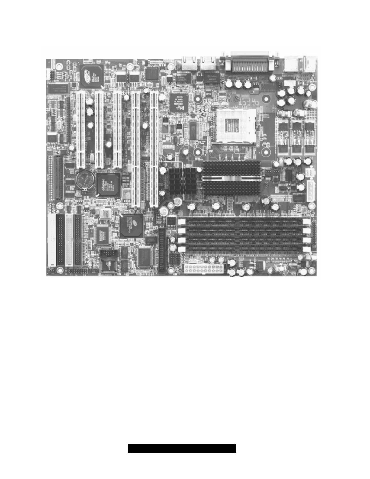
2.0 – Board Image
The following is an image of the S2707 Trinity GC- SL.
The above photograph is purely representative. Due to engineering updates and new board
revisions, certain components may change and or be repositioned. The picture above may
or may not look exactly like the board you received.
The following page includes details on the vital components of this motherboard.
7
http://www.tyan.com
Page 8

2.1 – Board Parts
This jumper diagram is representative of the latest board revision available at the time of
publishing. The board you receive may or may not look exactly like the above diagram.
The board parts are not to scale.
8
http://www.tyan.com
Page 9

2.2 – Jumper Settings
Jumper Function Settings Ref. Page
JP1
JP9
JP10
JP11
JP20
JP22
JP23
JP24
JP25
JP30
JP31
JP38
2.3 – Connectors
CMOS Clear
PCI- (X) Bus1/Slot #1 PCI -X/PCI
Mode
PCI- (X) Bus2/Slot #2 PCI -X/PCI
Mode
PCI- (X) Bus1/Slot #1 PCI -X 133
or 100 MHz
Reserved
Enable/Disable onboard Intel
82545EM GbE NIC
Enable/Disable CPU Thermal
Trip power down feature
Enable/Disable onboard Intel
82551QM/82540EM NIC
Enable/Disable onboard SCSI
controller
Enable/Disable onboard
Promise IDE RAID controller
Enable/Disable onboard ATI
Rage XL PCI VGA controller
Watchdog Timer Control Open: Disable
Open: Normal (Default)
Close: CMOS Clear Mode
Open: PCI -X Mode (Default)
Close: PCI Mode
Open: PCI -X Mode (Default)
Close: PCI Mode
Open: PCI-X 100 MHz
Close: PCI-X 133 MHz (Default)
Open: Enable (Default)
Close: Disable
Open: Enable (Default)
Close: Disable
Open: Enable (Default)
Close: Disable
Open: Enable (Default)
Close: Disable
Open: Enable (Default)
Close: Disable
Open: Enable (Default)
Close: Disable
Close: Enable
Hardwire : Enable (Default)
Page 11
Page 11
Page 12
Page 11
Page 12
Page 15
Page 13
Page 13
Page 14
Page 14
Page 15
Connector Function
J1
J2
J21
J22
J26
J27
J30
J32
J33
J36
J38
J40
COM2
CPUFAN1
FAN2
FAN3
FAN4
External LED header for Processor-hot warning; same as onboard LED D1
ITP connector (It is for development purpose and may be present onboard.)
PS/2 keyboard (lower) and PS/2 mouse (upper) connectors
Front panel header
RJ45 LAN connector for onboard Intel 82551QM/82540EM NIC
VGA connector for onboard ATI Rage XL PCI VGA
Front USB headers
Hardware monitor warning beep/LED output (optional)
RJ45 LAN connector for onboard Intel 82545EM NIC
External speaker header
Auxiliary LAN LED headers for onboard Intel 82545EM NIC
Auxiliary LAN LED headers for onboard Intel 82551QM/82540EM NIC
COM2 2x5 pin header
3- pin CPU fan connector with PWM fan control and fan speed reading
3- pin fan connector with PWM fan control and fan speed reading
3- pin fan connector with PWM fan control and fan speed reading
3- pin CPU fan connector with fan speed reading
9
http://www.tyan.com
Page 10
Jumper Legend
ED +
Jumper OFF (without pin)
Jumper ON (with pin)
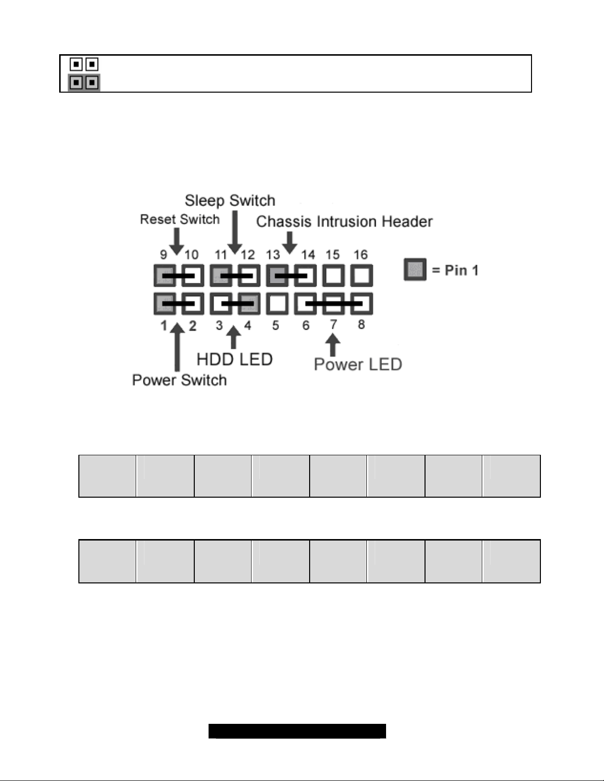
2.4 – Front Panel Connector (J22)
Your chassis will usually come with connectors to install onto the motherboard, such as HDD and
Power LEDs. The Front Panel Connector (J22) has been implemented for such purposes.
J22 Pinout
Pin 9
Reset
(signal)
Pin 1
Power
SW
Pin 10
Reset
(GND)
Pin 2
GND HDD
Pin 11
SLP_SW
(signal)
Pin 3
LED -
Pin 12
SLP_SW
(GND)
Pin 4
HDD
L
Pin 13
Intrusion GND NC NC
Pin 5
Key Power
Pin 14
Pin 6
LED
(green)
Pin 15
Pin 7
GND Power
Pin 16
Pin 8
LED
(yellow)
10
http://www.tyan.com
Page 11
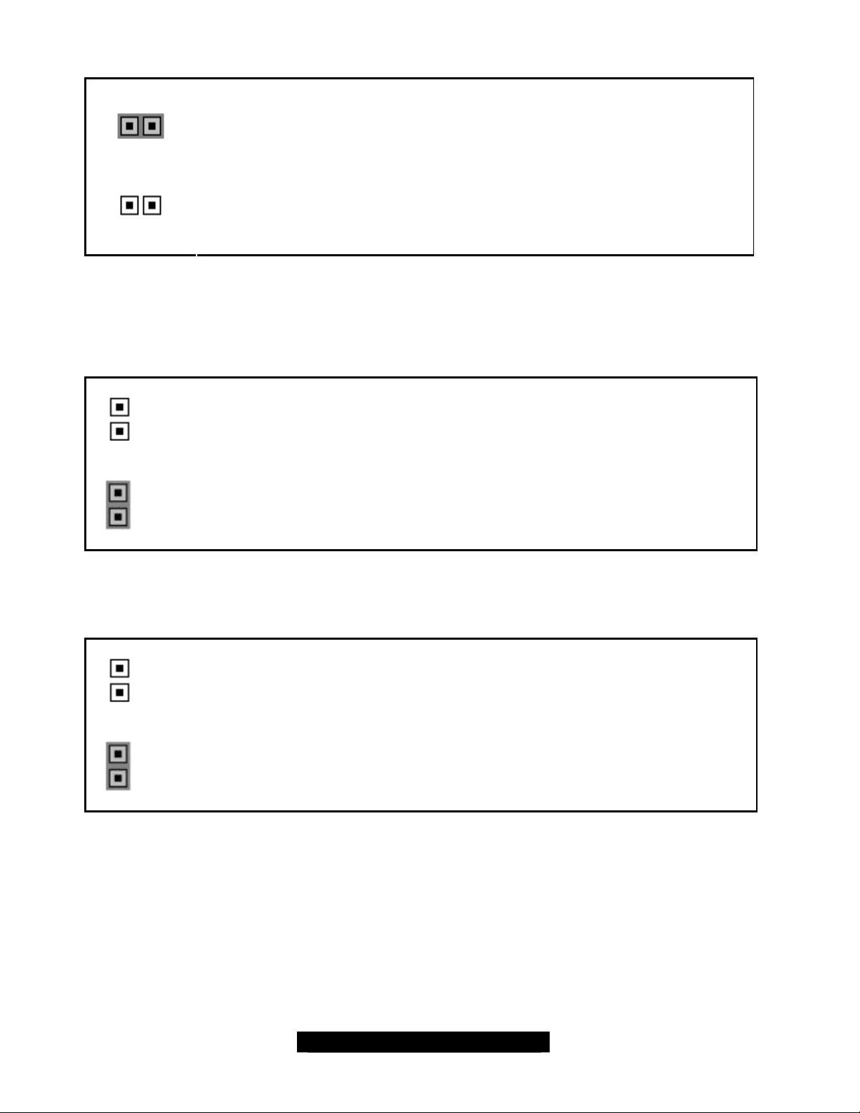
2.5 – Clear CMOS (JP1)
1
Clear CMOS
1
Default
2.6 – 64-bit PCI Slot Selection
(JP9) (PCI-X Slot#1 at PCI Bus 1, for slot located closest to the CPU)
You can reset the CMOS settings in case you have forgotten your system/setup
password or have just cleared your BIOS by u sing the jumpers.
• Power off system and disconnect the AC power from the power supply.
• Set jumper JP1 to Clear CMOS.
• Power system on and wait for the screen to show this message: “CMOS
Settings Wrong, CMOS Checksum Bad”. Now your CMOS is cleared.
• Go to BIOS Setup. Load and save setup defaults.
• Set jumper JP1 to Default (OPEN) for normal operations.
Open (default) the jumper to set the 64-bit slot to PCI-X mode.
Close the jumper to set the 64-bit slot to PCI mode.
(JP11) PCI -X (PCI slot 1) Frequency Selection
Open the jumper to set the slot to 100MHz.
Close (default) the jumper to set the slot to 133MHz.
11
http://www.tyan.com
Page 12
(JP10) (PCI-X Slot#2 at PCI Bus 2, for slot located next to the 32-bit PCI)
Open the jumper to set slots to PCI-X mode.
(This is the default setting for S2707GN)
Close the jumper to set the slots to PCI mode.
(This is the default setting for S2707UGN, if onboard AIC-7892x is present.)
Note:
§ No PCI-X 133/100 MHz jumper for Bus #2
Because this slot shares PCI Bus #2 with onboard 82545EM GbE and SCSI, the
Bus #2 has more than one device loads and cannot support PCI- X 133 MHz by
PCI- X specifications. Hence, there is no PCI-X 133MHz support for Bus #2.
§ PCI-X/PCI Mode on Bus #2
The onboard AIC- 7892x Ultra160 SCSI controller cannot support PCI-X mode,
JP10 should be set to CLOSE in this case. However, because the optional
AIC-7901 Ultra320 SCSI can support PCI -X model, JP10 can be set to OPEN for
S2707GN (non-SCSI) or with optional AIC- 7901.
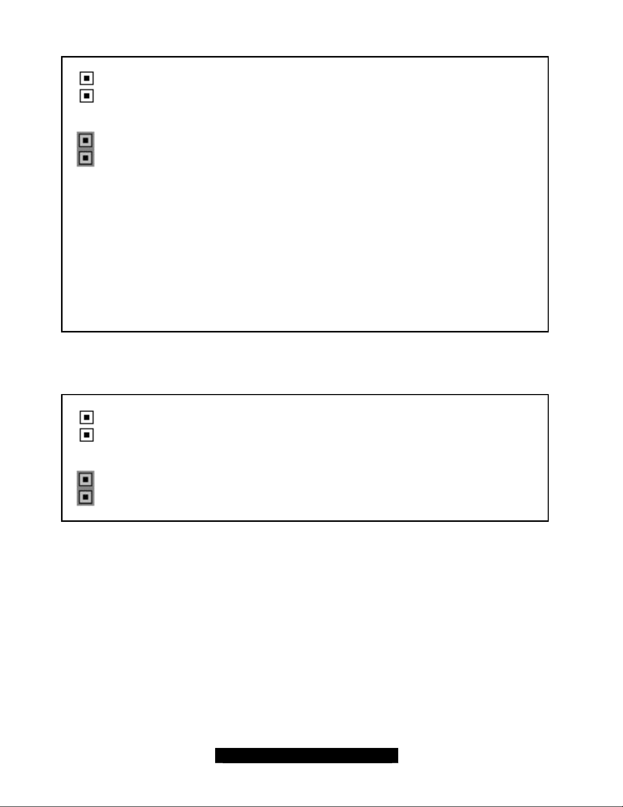
2.7 – Onboard LAN - Intel 82545EM Gigabit NIC (JP22)
Enabled
(default)
Disabled
Open the jumper(s) to enable the Onboard Intel 82545EM Gigabit
Ethernet chip.
CLOSE the jumper(s) to disable the Onboard Intel 82545EM Gigabit
Ethernet chip.
12
http://www.tyan.com
Page 13

2.8 – Onboard Intel 82545EM LAN LED Header (J38)
J38
Pin 1
Pin 2
LED_YEL+
LED_YEL-
Pin 3
Pin 4
2.9 – Onboard LAN - Intel 82551QM/82540EM NIC (JP24)
Enabled
(default)
Disabled CLOSE the jumper(s) to disable the Intel 82551QM/82540EM NIC port.
2.10 – Onboard Intel 82551QM/82540EM LAN LED Header (J40)
J40
Pin 1
LED_ GRN+
LED_GRN -
OPEN the jumper(s) to enable the Intel 82551QM/82540EM NIC chip.
LED_YEL+
Pin 2
Pin 3
Pin 4
LED_YEL-
LED_ GRN+
LED_GRN -
13
http://www.tyan.com
Page 14

2.11 – Onboard ATI RAGE XL Graphics (JP31)
Enabled
(default)
Disabled
2.12 – Onboard SCSI (JP25) (Optional)
2.13 – Onboard Promise RAID IDE Controller (JP30) (Optional)
Enabled
(default)
Disabled CLOSE the jumper to disable.
Enabled
(default)
OPEN the jumper to enable the onboard ATI RAGE XL graphics
controller. You can also use the onboard video in conjunction with
another PCI graphics card for multiple monitor support.
CLOSE the jumper to disable the onboard ATI RAGE XL.
OPEN the jumper to enable the onboard SCSI feature.
OPEN the jumper(s) to enable the Promise RAID IDE Controller.
Disabled CLOSE the jumper(s) to disable the Promise RAID IDE Controller.
2.14 – Chassis Intrusion Header (J22 – pins 13, 15)
Certain chassis have a switch that detects whether or not they are being opened. This switch
connects to the Chassis Intrusion Header to sound an alarm when the chassis is being opened
without authorization. Another 4- pin chassis intrusion header, J34, is included in the PCB design
as a manufacturing loading option.
J34
(optional)
Pin 4
GND
Pin 3
Intrusion
Pin 2
NC
Pin1
NC
14
http://www.tyan.com
Page 15

2.15 – CPU Thermal Trip (JP23)
Enabled
2.16 – Watchdog Timer Control (JP38)
No
Header
(default)
Disabled
Hardwired
OPEN the jumper(s) to enable the Thermal Trip.
The processor protects itself from overheating by the use of an internal
thermal sensor. When the Thermal Trip is enabled, the system will shut
off if temperature reaches approximately 135º Celsius. The processor
then stops all executions.
CLOSE the jumper(s) to disable the Thermal Trip. System will not shut
off when the CPU junction temperature reaches 135º Celsius.
HARDWIRE the built–in watchdog timer can reset your system if system
is hung up or goes down.
Disabled OPEN the jumper to disable the watchdog timer control.
Reset
(default)
2.17 – Fan Connectors
FAN PWM Fan Control Fan Tachometer/Speed Reading
CPUFAN1
FAN2
FAN3
FAN4
2.18 – Serial Port Headers (COM 2)
CLOSE the built–in watchdog timer can reset your system if system is
hung up or goes down.
Use these headers to connect cooling fans, both chassis and processor
fans, to your motherboard. Cooling fans help keep the system more
stable and operating reliably for its product life.
+12Volts (Max. 1 Ampere) fans supported (FAN4 Max. 1.25 Ampere)
Yes Yes
Yes Yes
Yes Yes
No No
15
http://www.tyan.com
Page 16

COM2
Pin 2
RXD DTR- DSR CTS NC
Pin 4
Pin 6
Pin 8
Pin 10
Pin 1
DCD TXD GND RTS RI
2.19 – USB Header (J30)
J30
Pin 2
GND GND USB_2+ USB_2- USB
Pin 1
USB
POWER
Note: The external USB cable is optional and not included in standard shipping box.
2.20 – Mounting the Motherboard
Pin 3
Pin 4
Pin 3
USB_3- USB_3+ GND GND
Pin 5
Pin 6
Pin 5
Pin 7
Pin 8
Pin 7
Pin 9
Pin 10
POWER
Pin 9
16
http://www.tyan.com
Page 17

Before installing your motherboard, make sure your chassis has the necessary motherboard
support studs installed. These studs are usually metal and are gold in color. Usually, the chassis
manufacturer will pre- install the support studs.
- Memory Type: The S2707 Trinity GC- SL only supports Registered DDR memory with ECC.
Non-registered or non -ECC DDR memory modules will NOT be supported.
- CPU Front-Side Bus Speed Match: The S2707 Trinity GC- SL memory frequency is
synchronized with both CPU and onboard memory controller front- side bus, which means the
memory module speed rate should match the CPU FSB. For example, with an Intel P4
533MHz Front-Side Bus (FSB) processor, the memory only supports DDR266/PC2100 Registered
ECC modules.
Below is a chart detailing what the most common motherboard studs look like and how they
should be installed.
TIP: Use metal studs if possible, as they hold the motherboard into place more securely than
plastic standoffs.
17
http://www.tyan.com
Page 18

2.21 – Installing the Memory
Before attempting to install any memory, make sure that the memory you have is compatible with
the motherboard as well as the processor. For example, while PC1600 DDR modules are
compatible with all DDR based motherboards, they will not work if you are required to run the
motherboard and processor buses at 533MHz. For this, PC2100 DDR (DDR266) modules are
required. For important memory information, please check Tyan’s web site at: www.tyan.com for
recommendations.
The following diagram shows the types of RAM modules you may encounter depending on your
board:
Here are a few key points to note before installing memory into your Trinity GC-SL:
• At least ONE Registered DDR module with ECC must be installed for the system
to turn on and POST (Power-On-Self-Test)
• 128MB, 256MB, 512MB and 1GB Registered PC2100/PC1600 DDR memory modules
are supported
• All installed memory will be automatically detected - no need to set any jumpers
• The Trinity GC-SL supports up to 4GB of memory
18
http://www.tyan.com
Page 19

Memory Installation Procedure
When installing memory modules, make sure the modules align properly with the memory socket.
There should be keys (small indents) on your memory modules that fit according to the keys in the
memory socket. DDR modules and sockets have only one key, which is slightly near the center of
the module/socket. The SDR SDRAM modules and their sockets have two keys and will not insert
into DDR DIMM sockets. The method of installing memory modules is detailed in the following
diagrams.
Once the memory modules are firmly seated in the socket, two clamps on either side will close
and secure the module into the socket. Sometimes you may need to close the clamps manually.
To remove the memory module, simply push the clamps outwards until the memory module pops
up. Then simply remove the module.
TIP: When installing memory, a module may require a considerable amount of force to seat
properly, although this is very rare. To avoid bending and damaging your motherboard, place it on
its anti -static bag and onto a flat surface, and then proceed with memory installation.
NOTE
YOU MUST unplug the power connector to the motherboard before performing
system hardware changes, to avoid damaging the board or expansion device.
19
http://www.tyan.com
Page 20

2.22 – Installing the Processor and Heatsink
This Trinity GC-SL S2707 supports the latest processor technologies from Intel. The latestgeneration Pentium 4 processors are supported by this motherboard. Check www.TYAN.com for
CPU compatibility information.
NOTE: Tyan is not liable for damage as a result of operating an unsupported configuration.
The processor you choose may not look exactly like the one pictured above, nor will the socket
look exactly the same. For exam ple, your processor may appear to be a different color and have
different markings on it. The diagram is a visual aid to help you install the processor correctly.
1. Lift the lever on the socket until it is approximately 90o, or as far back as possible
to the socket (DO NOT EXERT FORCE).
2. Align the processor with the socket. There are keys underneath the processor to ensure
that it inserts correctly.
3. Seat the processor firmly into the socket by gently pressing down until the processor
sits flush with the socket.
4. Place the socket lever back down until it snaps into place.
5. Your processor is installed.
Take care when installing the processor, as it has extremely fragile connector pins that can
be bent or even break if the processor is inserted incorrectly.
Heatsink Installation
After you are done installing the processor, you should proceed to installing the heatsink. The
heatsink will ensure that the processor does not overheat, and will continue to operate at
maximum performance. An overheated processor is also dangerous to the long- term reliability of
the motherboard.
20
http://www.tyan.com
Page 21

The following diagram will illustrate how to install the most common heatsinks:
First, use thermal compound (also
called heatsink compound or thermal
grease) and apply a small amount on
to the processor’s core – the small
shiny square in the center of the
processor.
You may then use a small soft plastic
tool, like a credit card to gently smear a
thin layer of heatsink compound as
evenly as you can across the core. In
most cases, you don’t need to do this
but it may help.
Then, at an angle, clip one side of the
heatsink onto the socket and then lay
the heatsink flat onto the processor.
Then clip the other end of the heatsink
down either with your finger or by using
a flathead screwdriver.
Some heatsinks have a small clip on
the inside of one of the clips which you
can insert a small flathead screw driver
into to secure the heatsink.
In most cases, either side of the
heatsink can be clipped down last, but
usually, the side of the socket where it
is raised, secures last.
Because one side of the socket is
raised (and usually has “SOCKET”
imprinted into it) heatsinks have an
indent on one side to secure flush with
the raised side of the socket.
Be sure to carefully observe which side
your heatsink is seated before securing
it down to avoid damaging the
Install the mounting bracket onto the motherboard by
aligning the bracket with the four holes around the
processor socket. Once the bracket is aligned, press
down on the four white pegs on the bracket until they
insert securely, locking the bracket onto the
motherboard. Then proceed to installing the heatsink.
Instructions on how to install heatsinks should be
provided with the heatsink itself.
processor, the heatsink or both.
21
http://www.tyan.com
Page 22

Finishing Installing the Heatsink
After you finish installing the heatsink onto the processor and socket, attach the end wire of the
fan (which should already be attached to the heatsink) to the motherboard. The following diagram
illustrates how to connect fans onto the motherboard.
After you’re complete the heatsink installation, you can connect your drives (hard drives, CD- ROM
drives, etc.) to your motherboard.
2.23 – Attaching Drive Cables
Attaching IDE drive cabling is simple. These cables are “keyed” to only allow them to be
connected in the correct manner. Tyan motherboards have two on-board IDE channels, each
supporting two drives. The black connector designates the Primary channel, while the white
connector designates the Secondary channel.
Attaching IDE cables to the IDE connectors is illustrated below:
Simply plug in the BLUE END of the IDE cable into the motherboard IDE connector, and the other
end(s) into the drive(s). Each standard IDE cable has three connectors, two of which are closer
together. The BLUE connector that is furthest away from the other two is the end that connects to
the motherboard. The other two connectors are used to connect to drives.
TIP: Pin 1 on the IDE cable (usually designated by a colored wire) faces the drive’s power
connector.
22
http://www.tyan.com
Page 23

Floppy Drives
Attaching a floppy drive can be done in a similar manner to an IDE drive. See the diagram below
for an example of a floppy cable. Most of the current floppy drives on the market require that the
cable be installed with the colored stripe positioned next to the power connector. In most cases,
there will be a key pin on the cable which will force proper connection of the cable.
The first floppy drive (sometimes denoted as
A:) is usually attached to the end of the cable
with the twist in it. Drive B: is usually connected
to the second or third connector in the cable
(the second or third connector after you install
Drive A:).
Refer to your floppy drive’s installation
instructions (if available), or contact your dealer
if you are unsure about how to attach the
floppy drive(s). Remember, you can only have
2 floppy drives connected at any given time.
Below are some symptoms of incorrectly installed floppy drives. While they are minor and
installing them incorrectly doesn’t cause severe problems, it may cause your system to freeze or
crash when trying to read and/or write to diskettes.
Symptoms of incorrectly installed floppy drives
Drive is not automatically detected
Drive Fail message at bootup
Drive does not power on
Drive activity light is constantly on
Usually caused by faulty cables, cables put in
backwards or a bad floppy drive or
motherboard. Try another floppy drive to verify
the problem if the cable is properly installed or
try replacing the actual cable. Also check to
see if the onboard floppy controller is enabled
in the BIOS setup.
The cable, floppy drive or motherboard may be
faulty. Try another drive or cable to verify.
Check power cable and cabling. Maybe a bad
power supply or drive cable problem.
Usually signifies that the cable on the drive is
on backwards, which is a common issue.
Reverse the cable at the floppy drive end and
try again.
23
http://www.tyan.com
Page 24

2.24 – Installing Add-In Cards
Before installing add- in cards, it’s helpful to know if they are fully compatible with your
motherboard. For this reason, we’ve provided the diagram below to show you the most common
slots that may appear on your motherboard. Not all of the slots shown will necessarily appear on
your motherboard. Instead, your motherboard will have combinations of what you see here.
Simply find the appropriate slot for your add- in card and insert the card firmly. Do not force any
add-in cards (or anything else) into any slots if they won’t seat in place. It’s better to try another
slot or return the faulty card rather than damaging both the motherboard and the add -in card.
TIP: It’s good practice to install add-in cards in a staggered manner, rather than directly adjacent
to each other. This allows air to more easily circulate within the chassis, providing improved
cooling for all installed devices.
NOTE YOU MUST UNPLUG the power connector to the motherboard before performing
system hardware changes, to avoid damaging the board or expansion device.
Before continuing onto the next section on connecting External Devices, make sure everything is
properly connected. Typically, jumpers and case wiring are the most common causes of
troubleshooting frustration,
24
http://www.tyan.com
Page 25

2.25 – Connecting External Devices
Connecting external devices to the motherboard is simple. Common external devices are
keyboards, mice, and printer cables. The following diagram will detail the ATX port stack for this
motherboard:
S2707 Trinity GC-SL
Optional 32-bit PCI 1Gbit Ethernet Port (Intel 82540EM)
Depending on the individual motherboard design, the PS/2 keyboard and mouse ports may
sometimes have their positions swapped. The most common designs implemented today place
the keyboard connector closest to the motherboard, while the top connector is for the mouse.
Although primarily to connect printers, the parallel printer port is also used for devices such as ZIP
drives, external CD-RW drives, scanners, and other external devices. Serial ports, also known as
COM ports, are primarily used to connect external modems and other RS- 232C devices.
25
http://www.tyan.com
Page 26

2.26 – Installing the Power Supply
There are three power connectors on this motherboard. By default, this motherboard requires that
you have an ATX12V power supply that has the standard ATX-style 20-pin connector, as well as
an additional 4-pin square connector. The CPU power is provided by the onboard switching
voltage regulator, which is sourced by +12V power. This +12V CPU power source is from the
onboard 4-pin square connector and the 4- pin auxiliary drive power connector. The +12V power
on the 20- pin ATX power connector is for system board and separated from CPU +12V regulator
power source. Therefore, the CPU won't be powered neither connecting the 4-pin square
ATX 12V power connector nor 4-pin auxiliary power connector.
In addition to the onboard 4- pin square connector for CPU regulator power, the onboard 4-pin
auxiliary drive power connector provides one additional +12V power wire.
Power connectors for CPU
VRM source
4-- pin square connector only 2 12 Amperes
4-- pin aux. connector only 1 6 Amperes
4-- pin square plus 4-pin aux.
connectors
Number of 12-V power wire Max. Current Rating
3 18 Amperes
26
http://www.tyan.com
Page 27

2.27 – Finishing Up
Congratulations on making it this far! You’re finished setting up the hardware aspect of your
computer. Before closing up your chassis, make sure that all cables and wires are connected
properly, especially IDE cables and most importantly, jumpers. You may have difficulty powering
on your system if the motherboard jumpers are not set correctly.
In the rare circumstance that you have experienced difficulty, even though the instructions herein
were followed, you can find help by asking your vendor for assistance. If they are not available for
assistance, please find setup information and documentation online at our website or by calling
your vendor’s support line.
27
http://www.tyan.com
Page 28

Chapter 3: BIOS Setup
Installation
The BIOS is the basic input/output system, the firmware on the motherboard that enables your
hardware to interface with your software. This chapter describes different settings for the BIOS
that can be used to configure your system.
The BIOS section of this manual is subject to change without notice and is provided for reference
purposes only. The settings and configurations of the BIOS are current at the time of print, and
therefore may not match exactly what is displayed on screen.
This section describes the BIOS setup program. The setup program lets you modify basic
configuration settings. The settings are then stored in a dedicated, battery-backed memory (called
NVRAM) that retains the information when the power is turned off.
This motherboard’s BIOS is a customized version of the industry-standard BIOS for x86-
compatible personal computers. The BIOS provides critical, low-level support for the system’s
central processing unit (CPU), memory, and I/O subsystems.
This BIOS has been customized by adding important features such as virus and password
protection, power management, and chipset “tuning” features that control the system. This section
will guide you through the process of configuring the BIOS for your system setup.
Starting Setup
The BIOS is immediately activated when you turn on the computer. The BIOS reads system
configuration in CMOS RAM and begins the process of checking out the system and configuring it
through the Power-On-Self- Test (POST).
When these preliminary tests are complete, the BIOS searches for an operating system on one of
the system’s data storage devices (hard drive, CD-ROM, etc). If one is found, the BIOS will launch
that operating system and hand control over to it. You can enter the BIOS setup by pressing the
[Delete] key when the machine boots up and begins to show the memory count.
28
http://www.tyan.com
Page 29

Setup Basics
The table below shows how to navigate in the setup program using the keyboard.
Key Function
Tab Moves from one selection to
the next
Left/Right Arrow Keys Change from one menu to the
next
Up/Down Arrow Keys More between selections
Enter Opens highlighted section
PgUp/PgDn Keys Change settings.
Getting Help
Pressing [F1] will display a small help window that describes the appropriate keys to use and the
possible selections for the highlighted item. To exit the Help Window, press [ESC] or the [F1] key
again.
In Case of Problems
If you discover that you have trouble booting the computer after making and saving the changes
with the BIOS setup program, you can restart the computer by holding the power button down until
the computer shuts off (usually within 4 seconds); resetting by pressing CTRL-ALT-DEL; or
clearing the CMOS.
The best advice is to only alter settings that you thoroughly understand. In particular, do not
change settings in the Chipset section unless you are absolutely sure of the outcome. The
Chipset defaults were carefully chosen by Tyan or your system manufacturer for the best
performance and reliability. Even a seemingly small change to the Chipset setup options may
cause the system to become unstable or unusable.
Setup Variations
Not all systems will have the same BIOS setup layout or options. While the basic look and function
of the BIOS setup remains more or less the same for most systems, the appearance of your Setup
screen may differ from the charts shown in this section. Each system design and chipset
combination requires a custom configuration. In addition, the final appearance of the Setup
program depends on the system designer. Your system designer may decide that certain items
should not be available for user configuration, and remove them from the BIOS setup program.
NOTE: On the following pages, options written in bold type represent the BIOS Setup default.
29
http://www.tyan.com
Page 30

3.1 – Main BIOS Setup
In this screen, you can alter general features such as the date and time, as well as access the IDE
configuration screens. Note that the options listed below are for options that can directly be
changed within the Main Setup screen.
BIOS Build Date MM/DD/YY
BIOS ID XXXXXXXX
Processor Type Intel Pentium 4
Processor Speed XXXXX GHz
System Memory XXXX MB
System Time [hh:mm:ss]
System Date [Day mm/dd/yyyy]
3.2 – Advanced Settings
Options such as I/O device interfaces can be altered through this screen.
Setup Warning:
Setting items on this screen to incorrect values may cause the system to malfunction!
Super IO Configuration
IDE Configuration
Floppy Configuration
Boot Settings Configuration
Peripheral Device Configuration
System Health Monitor
Remote Access Configuration
All settings discussed in following sections.
30
http://www.tyan.com
Page 31

3.3 – Chipset
Options related to the chipset can be altered through the following.
C000, 16K Shadow
C400, 16K Shadow
C800, 16K Shadow
CC00, 16K Shadow
D000, 16K Shadow
D400, 16K Shadow
C800, 16K Shadow
DC00, 16K Shadow
Memory Auto Precharge
Write Combining for
P6-to -PCI
Memory Write Posting
Scubbing Enable
Memory Timing Control
Support for 2.5 ns
CAS Latency
Watchdog Timer
Auto DQS Setting
Support
DQS Selection
Memory Enhanced
Mapping
Buffer Compensation
3.4 – PCI PnP
Options related to the Plug and Play PCI settings interface can be altered through the following.
Plug & Play O/S
Reset Config Data
PCI Latency Timer
Allocate IRQ to PCI
VGA
USB Function
Legacy USB
Support
ARMD Emulation
Type
[Cached]
[Cached]
[Cached]
[Cached]
[Disabled]
[Disabled]
[Disabled]
[Disabled]
[Disabled]
[Disabled]
[Enabled]
[Enabled]
[Auto]
[Enabled]
[Disabled]
[Enabled]
[16]
[Enabled]
[Disabled]
[Yes]
[No]
[64]
[Yes]
[Enabled]
[Auto]
[Hard Disk]
Toggles the option of letting the OS take care of IRQ
routing or the BIOS. Select Yes to let the OS manage
IRQ settings.
Resets BIOS area where IRQ and DMA settings are
stored.
Leave on 64 for best combination of performance and
stability.
Assigns an IRQ to PCI video card.
Turns onboard USB ports On or Off.
Enables USB legacy devices and functions.
Dependent on HDD specifications.
31
http://www.tyan.com
Page 32

3.5 – Power
ACPI Aware O/S
Instant ON/OFF
3.6 – Boot
Options related to boot devices can be altered through the following.
Boot Device Priority
Hard Disk Drives
Removable Devices
ATAPI CDROM Drives
3.7 – Security
Options related system security can be altered through the following.
Change Supervisor
Password
Change User Password Changes boot password.
Clear User Password Clears boot password.
Boot Sector Virus
Protection
3.8 – Exit
Options related exiting and saving can be done using the following.
Exit Saving Changes Exit and save options.
Exist Discarding Changes Exit but don’t save options.
Load Optimal Defaults Loads the BIOS setup with default settings.
Load Failsafe Defaults Loads the BIOS setup with more conservative setti ngs
Discard Changes Discards any changes made.
[Yes]
[Disabled]
1st Boot Device
2nd Boot Device
3rd Boot Device
Specifies the boot sequence for hard drive booting. This option
will show all storage devices.
Specifies the boot sequence for removable drive booting. This
option will show all removable devices.
Specifies the boot sequence for CD- ROM drive booting. This
option will show all CD-ROM devices.
Changes system password.
[Disabled]
Dependent on usage of ACPI-capable OS.
Dependent on usage of ACPI-capable OS.
Settings for boot priority. These can be
customized depending on your
preference.
Toggles protection of boot sector on the hard
drive from being modified.
32
http://www.tyan.com
Page 33

Chapter 4: Diagnostics
Note: if you experience problems with setting up your system, always check the following things in
the following order:
Memory, Video, CPU
By checking these items, you will most likely find out what the problem might have been when
setting up your system. For more information on troubleshooting, check the TYAN website at:
http://www.TYAN.com.
4.1 Beep Codes
Fatal errors, which halt the boot process, are communicated through a series of audible beeps.
For example, if the BIOS POST can initialize the video but an error occurs, an error message will
be displayed. If it cannot display the message, it will report the error as a series of beeps.
If you hear any beeps, please check your memory configuration, order, type, and check for faulty
modules. Please check our website for memory compatibility.
Before calling your vendor or calling TYAN Tech Support, be sure that you know how many beeps
your board made, and how long the beeps were. Also have other information such as your
attached add-in cards, drives and OS to help speed up the support process and come to a
possible solution faster.
4.2 Flash Utility
Every BIOS file is unique for the m otherboard it was designed for. For Flash Utilities, BIOS
downloads, and information on how to properly use the Flash Utility with your motherboard, you
must check the TYAN website: http://www.TYAN.com/
Please be aware that by flashing your BIOS, you agree that in the event of a BIOS
NOTE
flash failure, you must contact your dealer for a replacement BIOS. There are no
exceptions. Tyan does not have a policy for replacing BIOS chips directly with end
users. In no event will Tyan be held responsible for damages done by the end user.
33
http://www.tyan.com
Page 34

Appendix: Glossary
ACPI (Advanced Configuration and Power Interface): a power management specification that
allows the operating system to control the amount of power distributed to the computer’s devices.
Devices not in use can be turned off, reducing unnecessary power expenditure.
AGP (Accelerated Graphics Port): an interface specifically designed for the demands of 3D
graphics applications. The 32- bit AGP channel directly links the graphics controller to the system
memory. While the channel runs at just 66MHz, it supports data transmission during both the
rising and falling ends of the clock cycle, yielding an effective speed of 133MHz.
ATAPI (AT Attachment Packet Interface): also known as IDE or ATA; a drive implementation
that includes the disk controller on the device itself. It allows CD- ROMs and tape drives to be
configured as master or slave devices, just like hard drives.
ATX: the form factor designed to replace the AT form facto r. It improves on the AT design by
rotating the board 90 degrees, so that the IDE connectors are closer to the drive bays, and the
CPU is closer to the power supply and cooling fan. The keyboard, mouse, USB, serial, and
parallel ports are built-in.
Bandwidth: refers to carrying capacity. The greater the bandwidth, the more data the bus, phone
line, or other electrical path, can carry. Greater bandwidth, then, also results in greater speed.
BBS (BIOS Boot Specification): is a feature within the BIOS that creates, prioritizes, and
maintains a list of all Initial Program Load (IPL) devices, and then stores that list in NVRAM. IPL
devices have the ability to load and execute an O/S, as well as provide the ability to return to the
BIOS if the O/S load process fails for some reason. At that point, the next IPL device is called
upon to attempt loading of the O/S.
BIOS (Basic Input/Output System): the firmware that resides in the ROM chip, and provides the
basic instructions for controlling your computer’s hardware. Both the operating system and
application software use BIOS routines to ensure compatibility.
Buffer: a portion of RAM which is used to temporarily store data, usually from an application,
though it is also used when printing, and in most keyboard drivers. The CPU can manipulate data
in a buffer before copying it, all at once, to a disk drive. While this improves system performance --
- reading to or writing from a disk drive a single time is much faster than doing so repeatedly --there is also the possibility of losing your data should the system crash. Information stored in a
buffer is temporarily stored, not permanently saved.
Bus: a data pathway. The term is commonly used to refer to the connection between the
processor and system memory, and between the processor and AGP, PCI or ISA buses.
Bus mastering: allows peripheral devices and IDE controllers to access the system memory
without going through the CPU (similar to DMA channels).
Cache: a temporary storage area for data that will be needed often by an application. Using a
cache lowers data access times, since the needed information is stored in the SRAM instead of in
the slower DRAM. Note that the cache is also much smaller than your system memory: a typical
cache size is 512KB, while you may have as much as 4GB or more of system memory.
34
http://www.tyan.com
Page 35

Cache size : refers to the physical size of the cache. This should not be confused with the
cacheable area, which is the total amount of memory which can be scanned by the system in
search of data to put into the cache. A typical setup would be a cache size of 512KB, and a
cacheable area of 512MB. In this case, up to 512KB of system memory is capable of being
cached. However, only 512KB of this memory will be in the cache at any given moment.
Closed and open jumpers: jumpers and jumper pins are active when they are “on” or “closed”,
and inactive when they are “off” or “open”.
CMOS (Complementary Metal-Oxide Semiconductor): chips that hold the basic startup
information for the BIOS.
COM port: another name for the serial port, which is called such because it transmits the eight
bits of a byte of data along one wire, and receives data on another single wire (that is, the data is
transmitted in serial form, one bit after another). Parallel ports transmit the bits of a byte on eight
different wires at the same time (that is, in parallel form, eight bits at the same time).
DDR (Double Data Rate): is a technology designed to double the clock speed of the memory. It
activates output on both the rising and falling edge of the system clock rather than on just the
rising edge, potentially doubling throughput.
DIMM (Dual In-line Memory Module): faster and more capacious form of RAM than SIMMs.
DIMM bank: sometimes called DIMM sockets, because the physical slot and the logical unit are
the same. That is, one DIMM module fits into one DIMM socket, which is capable of acting as a
memory bank.
DMA (Direct Memory Access): channels that are similar to IRQs. DMA channels allow hardware
devices (like soundcards or keyboards) to access the main memory without involving the CPU.
This frees up CPU resources for other tasks. As with IRQs, it is vital that you do not double up
devices on a single line. Plug-n-Play devices will take care of this for you.
Doze mode: in this mode, only the CPU’s speed is slowed.
DRAM (Dynamic RAM): widely available, very affordable form of RAM which will lose data if it is
not recharged regularly (every few milliseconds). This refresh requirement makes DRAM three to
ten times slower than non-recharged RAM such as SRAM.
ECC (Error Correction Code or Error Checking and Correcting): allows data to be checked for
errors during run- time. Errors can subsequently be corrected at the same time that they’re found.
EEPROM (Electrically Erasable Programmable ROM): also called Flash BIOS, is a ROM chip
which can, unlike normal ROM, be updated. This allows you to keep up with changes in the BIOS
programs without having to replace the BIOS chip. Tyan’s BIOS updates can be found at
http://www.tyan.com.
ESCD (Extended System Configuration Data): a format for storing information about Plug-nPlay devices in the system BIOS. This information helps properly configure the system each time
it boots.
Fault -tolerance: a term describing a system where one component can quickly be replaced
without causing a loss of service, such as in a RAID system.
Firmware: low-level software that controls the system hardware.
35
http://www.tyan.com
Page 36

Form factor: an industry term for the size, shape, power supply type, and external connector type
of the Personal Computer Board (PCB) or motherboard. The most common form factors in use
today are; ATX, microATX, FlexATX, Extended ATX, SSI EEB, and SSI MEB.
Global timer: onboard hardware timer, such as the Real -Time Clock (RTC).
Handshaking: a form of encryption. One system, typically the server, sends an encryption
scheme to another agent, typically a client. Thus, the client’s data is protected during transmittal to
the server.
HDD: stands for Hard Disk Drive, a type of fixed drive.
H-SYNC: controls the horizontal synchronization/properties of the monitor.
IC (Integrated Circuit): the common, formal name for a computer chip.
IDE (Integrated Device/Drive Electronics): a simple, self-contained HDD interface. It can handle
drives up to 8.4 GB in size. Almost all IDE drives sold today are a form of Enhanced IDE (EIDE),
with maximum capacity determined by the hardware controller.
IDE INT (IDE Interrupt): a hardware interrupt signal that goes to the IDE.
I/O (Input/Output): the connection between a computer and another device (mouse, keyboard,
etc.)
Initial Program Load (IPL): a feature built into BBS-compliant devices, describing those devices
as capable of loading and executing an O/S, as well as being able to provide control back to the
BIOS if the loading attempt fails.
IPL: see Initial Program Load.
IRQ (Interrupt Request): an electronic request that runs from a hardware device to the CPU. The
interrupt controller assigns priorities to incoming requests and delivers them to the CPU. It is
important that there is only one device hooked up to each IRQ line. Doubling up devices on IRQ
lines can cause problems. Plug- n-Play operating systems can take care of these details for you.
ISA (Industry Standard Architecture): a slower 8- or 16-bit bus (data pathway). The original IBM
PC, PC-XT, and PC-AT utilized these bus architectures.
Latency: the amount of time that one part of a system spends waiting for another part to catch up.
This is most common when the system sends data out to a peripheral device, and waits for the
peripheral to send data back (peripherals tend to be slower than onboard system components).
Mirroring: see RAID.
NVRAM: ROM and EEPROM are both examples of Non -Volatile RAM, memory that holds its data
without power. DRAM, in contrast, is volatile.
OEM (Original Equipment Manufacturer): manufacturers that commonly package other
companies’ motherboards and hardware inside their chassis and sell them.
Parallel port: transmits the bits of a byte on eight different wires at the same time (that is, in
parallel form, eight bits at the same time).
PCI (Peripheral Component Interconnect): a 32 or 64-bit local bus (data pathway) which is
faster than the ISA bus. Local buses are those which operate within a single system (as opposed
to a network bus, which connects multiple systems).
36
http://www.tyan.com
Page 37

PCI PIO (PCI Programmable Input/Output) modes: the data transfer modes used by IDE drives.
These modes use the CPU for data transfer (in contrast, DMA channels do not). PCI refers to the
type of bus used by these modes to communicate with the CPU.
PCI-to-PCI bridge: allows you to connect multiple PCI devices onto one PCI bus.
Pipeline burst SRAM: a fast secondary cache. It is used as a secondary cache because SRAM
is slower than SDRAM, but usual ly larger. Data is cached first to the faster primary cache, and
then, when the primary cache is full, to the slower secondary cache.
Pipelining: improves system performance by allowing the CPU to begin executing a second
instruction before the first is completed. A pipeline can be likened to an assembly line, with a given
part of the pipeline repeatedly executing a set part of an operation on a series of instructions.
PM timers (Power Management timers): software timers that count down the number of
seconds or minutes until the system times out and enters sleep, suspend, or doze mode.
PnP (Plug-n-Play): a design standard that has become ascendant in the industry. Plug- n-Play
devices require little set- up to use. Novice end users can simply plug them into a computer that is
running on a Plug-n-Play aware operating system (such as Windows 98/Me/XP), and go to work.
Devices and operating systems that are not Plug-n-Play require you to reconfigure your system
each time you add or change any part of your hardware.
PXE (Preboot Execution Environment): one of four components that together make up the
Wired for Management 2.0 baseline specification. PXE was designed to define a standard set of
preboot protocol services within a client, towards the goal of allowing networked-based booting to
boot using industry standard protocols.
RAID (Redundant Array of Independent/Inexpensive Disks): a way for the same data to be
stored in different places on many hard drives. By using this method, the data is stored
redundantly, also the multiple hard drives will appear as a single drive to the O/S. RAID Level 0 is
is known as striping, where data is striped (or overlapped) across multiple hard drives, but offers
no fault-tolerance. RAID Level 1 is known as mirroring, which stores the data within at least two
hard drives, but does not stripe. RAID Level 1 also allows for faster access time and faulttolerance, since either hard drive can be read at the same time. RAID Level 0+1 features both
striping and mirroring, providing fault-tolerance, striping, and faster access, all at the same time.
RAM (Random Access Memory): technically refers to a type of memory where any byte can be
accessed without touching the adjacent data, is often used to refer to the system’s main memory.
This memory is available to any program running on the computer.
ROM (Read-Only Memory): a storage chip which contains the BIOS; the basic instructions
required to boot the computer and start up the operating system.
SDRAM (Synchronous Dynamic RAM): called as such because it can keep two sets of memory
addresses open simultaneously. By transferring data alternately from one set of addresses and
then the other, SDRAM cuts down on the delays associated with non-synchronous RAM, which
must close one address bank before opening the next.
Serial port: called as such because it transmits the eight bits of a byte of data along one wire, and
receives data on another single wire (that is, the data is transmitted in serial form, one bit after
another).
Sleep/Suspend mode: in this mode, all devices except the CPU shut down.
37
http://www.tyan.com
Page 38

SRAM (Static RAM): unlike DRAM, this type of RAM does not need to be refreshed in order to
prevent data loss. Thus, it is faster and more expensive.
SSI (Server System Infrastructure): Industry design specification for server baseboards and
systems. Encompasses full-AT-sized boards and related integrated items.
Standby mode: in this mode, the video and hard drives shut down; all other devices continue to
operate normally.
Striping: see RAID
UltraDMA- 33/66/100/133 (aka ATA-133/100/66/33): a fast version of the original DMA channel.
UltraDMA is also called UltraATA. Without a proper UltraDMA controller, your system cannot take
advantage of higher data transfer rates of the new UltraDMA/UltraATA hard drives.
USB (Universal Serial Bus): a versatile port. This one port type can function as a serial, parallel,
mouse, keyboard or joystick port. It is fast enough to support video transfer, and is capable of
supporting up to 127 daisy -chained peripheral devices.
VGA (Video Graphics Array): the PC video display standard
V- SYNC: controls the vertical scanning properties of the monitor.
ZIF Socket (Zero Insertion Force socket): these sockets make it possible to insert CPUs without
damaging the sensitive CPU pins. The CPU is lightly placed in an open ZIF socket, and a lever is
pulled down. This shifts the processor over and down, guiding into the board and locking it into
place.
38
http://www.tyan.com
Page 39

Technical Support
If a problem arises with your system, you should first turn to your dealer for assistance. Your
system has most likely been configured by them, and they should have the best idea of what
hardware and software your system contains. Hence, they should be the most able to help.
Furthermore, if you purchased your system from a dealer near you, you can actually bring your
system to them to have it serviced, instead of having to do so yourself.
Help Resources:
1. See the beep codes section of this manual.
2. See the Tyan web site for FAQs, bulletins, driver updates, and other
information: http://www.tyan.com.
3. Contact your dealer for help BEFORE contacting Tyan.
4. Check the Tyan user group: alt.comp.periphs.mainboard.tyan
Returning Merchandise for Service
During the warranty period, contact your distributor or system vendor FIRST for any product
problems. This warranty only covers normal customer use and does not cover damages incurred
during shipping or failure due to the alteration, misuse, abuse, or improper maintenance of the
motherboard.
NOTE: A receipt or copy of your invoice marked with the date of purchase is required
before any warranty service can be rendered. You may obtain service by calling the
manufacturer for a Return Merchandise Authorization (RMA) number. The RMA number
should be prominently displayed on the outside of the shipping carton and the package
should be mailed prepaid. Tyan will pay to have the board shipped back to you.
39
http://www.tyan.com
Page 40

Notice for the USA
Compliance Information Statement (Declaration of Conformity Procedure) DoC
FCC Part 15: Th is device complies with part 15 of the FCC Rules
Operation is subject to the following conditions:
1) This device may not cause harmful interference, and
2) This device must accept any interference received including interference that may
cause undesired operation. If this equipment does cause harmful interference to radio
or television reception, which can be determined by turning the equipment off and on,
the user is encouraged to try one or more of the following measures:
• Reorient or relocate the receiving antenna.
• Increase the separation between the equipment and the receiver.
• Plug the equipment into an outlet on a circuit different from that of the
receiver.
• Consult the dealer on an experienced radio/television technician for help.
Notice for Canada
This apparatus complies with the Class B limits for radio interference as specified in the Canadian
Department of Communications Radio Interference Regulations. (Cet appareil est conforme aux
norms de Classe B d’interference radio tel que specifie par le Ministere Canadien des
Communications dans les reglements d’ineteference radio.)
Notice for Europe (CE Mark)
This product is in conformity with the Council Directive 89/336/EEC,
CAUTION: Lithium battery included with this board. Do not puncture, mutilate, or dispose of
battery in fire. Danger of explosion if battery is incorrectly replaced. Replace only with the same or
equivalent type recommended by manufacturer. Dispose of used battery according to
manufacturer instructions and in accordance with your local regulations.
92/31/EEC (EMC).
Document #: D1485 - 102
40
http://www.tyan.com
 Loading...