

Tyan THUNDER K8S PRO User Manual

Thunder K8S Pro
///
Revision 1.02
Copyright © TYAN Computer Corporation, 2001-2004. All rights reserved. No part of this
manual may be reproduced or translated without prior written consent from TYAN
Computer Corp.
All registered and unregistered trademarks and company names contained in this manual
are property of their respective owners including, but not limited to the following.
TYAN, Thunder K8S Pro are trademarks of TYAN Computer Corporation.
AMD, Opteron, and combinations thereof are trademarks of AMD Corporation.
AMI, AMIBIOS8 are trademarks of American Megatrends Inc.
Microsoft, Windows are trademarks of Microsoft Corporation.
SuSE,is a trademark of SuSE AG.
Linux is a trademark of Linus Torvalds
IBM, PC, AT, and PS/2 are trademarks of IBM Corporation.
Winbond is a trademark of Winbond Electronics Corporation.
Broadcom
ATI and Rage XL are trademarks of ATI Corporation
Silicon Image is a trademark of Silicon Image, Inc.
Information contained in this document is furnished by TYAN Computer Corporation and
has been reviewed for accuracy and reliability prior to printing. TYAN assumes no liability
whatsoever, and disclaims any express or implied warranty, relating to sale and/or use of
TYAN products including liability or warranties relating to fitness for a particular purpose
or merchantability. TYAN retains the right to make changes to product descriptions and/or
specifications at any time, without notice. In no event will TYAN be held liable for any
direct or indirect, incidental or consequential damage, loss of use, loss of data or other
malady resulting from errors or inaccuracies of information contained in this document.
®
is a trademark of Broadcom Corporation and/or its subsidiaries
S2882
1
http://www.TYAN.com

Table of Contents
Before you begin… Page 4
Chapter 1: Introduction
Congratulations Page 5
Hardware Specifications Page 5
Software Specifications Page 6
Chapter 2: Board Installation
2.00 Board Image Page 8
2.01 Block Diagram Page 9
2.02 Board Parts, Jumpers and Connectors Page 10
2.03 Gigabit LAN_1 Front Panel LED Header (J1) and Gigabit LAN_2
Front Panel LED Header (J2)
2.04 Front Panel Connector (J6) Page 12
2.05 Clear CMOS Jumper (J8) Page 13
2.06 SMBus_0 Connector (J11) Page 13
2.07 USB Connector Headers (J12) Page 14
2.08 10/100 LAN front Panel LED Header (J17) Page 14
2.09 Chassis Intrusion Connector (J19) Page 15
2.10 ZCR Connector (J22) Page 15
2.11 COM2 Header (J23) Page 16
2.12 PCI-X Bridge B (PCI 1 & PCI 2) PCI-X Speed Select Jumper (J24 /
J39)
2.13 PCI-X Bridge A (PCI 3 & PCI 4) force PCI Mode Jumper (J41) Page 17
2.14 Keylock Enable/Disable Jumper (J42) Page 17
2.15 PCI-X Bridge A (PCI 3 & PCI 4 & SCSI7902 & BCM5704) PCI-X
Speed Select Jumper (J43)
2.16 SMDC Connector (J45) Page 18
2.17 Onboard VGA Enable / Disable Jumper (J46) Page 19
2.18 Onboard Gigabit Ethernet Enable / Disable Jumper (J52) Page 19
2.19 Onboard 10/100 Ethernet Enable / Disable Jumper (J60) Page 20
2.20 ZCR Card Connector Select Jumper (J61) Page 20
2.21 CPU_1 Fan Connector (P1_FAN) (J5) Page 21
2.22 CPU_2 Fan Connector (P2_FAN) (J47) Page 21
2.23 FAN 1 Chassis Fan Connector (J44) Page 22
2.24 FAN 2 Chassis Fan Connector (J48) Page 22
2.25 FAN 3 Chassis Fan Connector (J4) Page 23
2.26 FAN 4 Chassis Fan Connector (J9) Page 23
2.27 FAN 5 Chassis Fan Connector (J3) Page 24
2.28 OEM Reserved Connectors and Jumpers Page 24
2.29 Installing the Processor(s) Page 25
2.30 Heatsink Retention Frame Installation Page 25
2.31 Thermal Interface Material Page 26
2.32 Heatsink Installation Procedures Page 27
2.33 Finishing Installing Heatsink Page 28
2.34 Tips on Installing Motherboard in Chassis Page 29
2.35 Installing the Memory Page 30
2.36 Attaching Drive Cables Page 32
2.37 Installing Add-In Cards Page 34
2.38 PCI Riser Cards Supported on S2882 K8S Page 35
2.39 Connecting External Devices Page 35
2.40 Installing the Power Supply Page 36
2.41 Finishing Up Page 36
Page 12
Page 16
Page 18
2
http://www.TYAN.com

Chapter 3: BIOS
3.00 BIOS Setup Utility Page 37
3.01 BIOS Menu Bar Page 38
3.02 BIOS Legend Bar Page 38
3.03 BIOS Main Menu Page 39
3.04 BIOS Advanced Menu Page 40
3.05 BIOS PCI/PnP Menu Page 54
3.06 BIOS Boot Settings Menu Page 56
3.07 BIOS Security Menu Page 62
3.08 BIOS Chipset Setting Menu Page 63
3.09 BIOS Power Menu Page 69
3.10 BIOS Exit Menu Page 70
Chapter 4: Diagnostics Page 71
Appendix I: Glossary
Appendix II: SMDC Information
Technical Support
Page 72
Page 77
Page 78
3
http://www.TYAN.com
Before you begin…
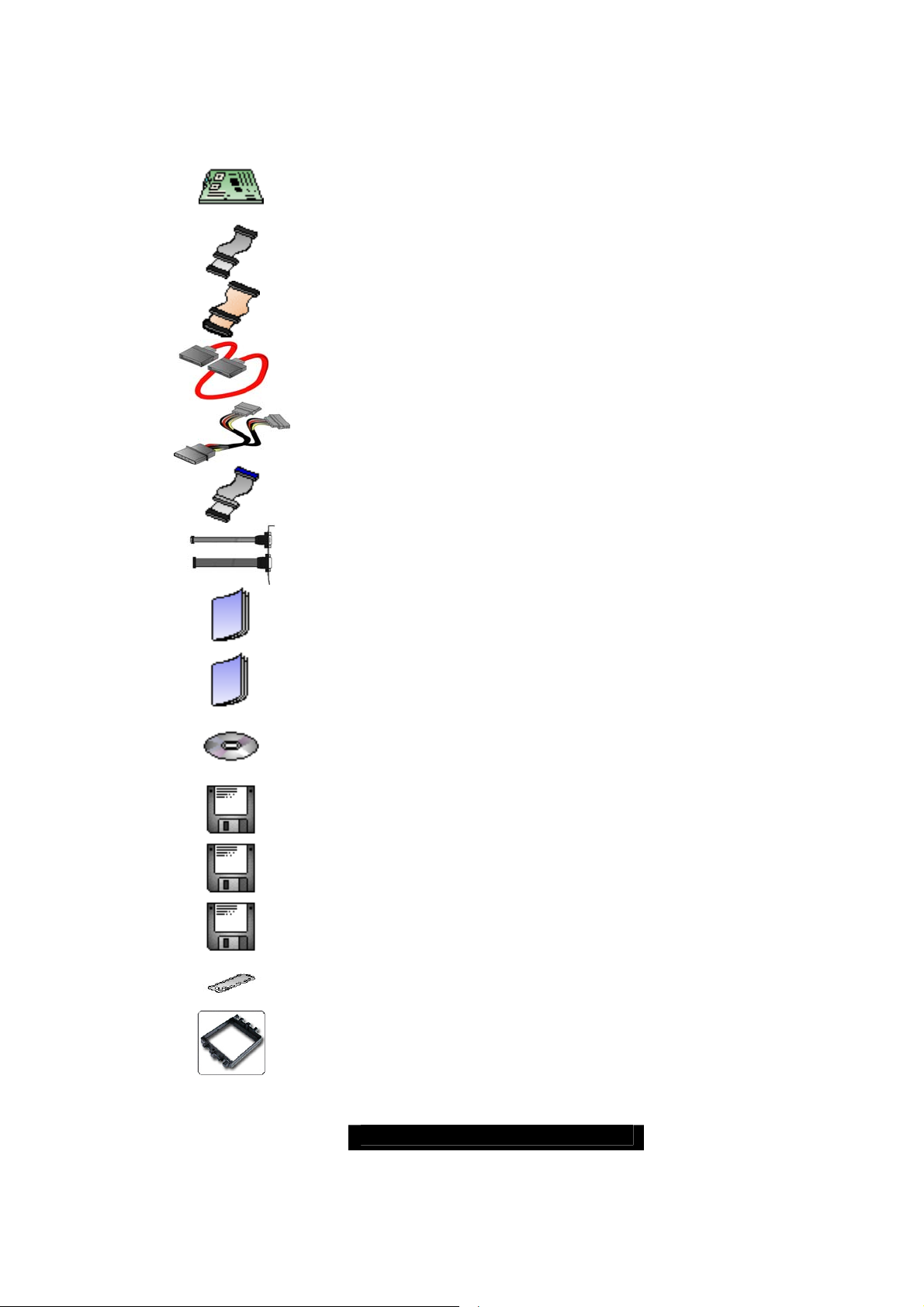
Check the box contents!
The retail motherboard package should contain the following:
1x Thunder K8S Pro motherboard
1x 34-Pin floppy drive cable
1x LVD SCSI cable (if optional SCSI included)
4 x SATA cable
2 x SATA Drive Power Adapter
2 x Ultra-DMA-133/100/66 IDE cable
1 x Cable set: 9-pin Serial and 25-pin Parallel
1 x Thunder K8S Pro user’s manual
1 x Thunder K8S Pro Quick Reference guide
1 x TYAN driver CD
1 x SCSI driver diskette (if optional SCSI included)
1x Silicon Image SiI3114 SATA RAID driver diskette
1x Silicon Image SiI3114 SATA Link driver diskette
1 x I/O shield
2 x CPU Retention Frame
If any of these items are missing, please contact your vendor/dealer for replacement
before continuing with the installation process.
4
http://www.TYAN.com

Chapter 1: Introduction
Congratulations
You are now the owner of the ideal solution for rackmount servers, large computer
clusters, or pedestal server needs. The Tyan Thunder K8S Pro features support for Dual
AMD Opteron processor(s), two channel Gigabit Ethernet, one 10/100 Ethernet and Serial
ATA (SATA).
Remember to visit TYAN’s Website at http://www.TYAN.com
information on all of TYAN’s products with FAQs, online manuals and BIOS upgrades.
Hardware Specifications
. There you can find
Processor
● Dual µPGA 940-pin ZIF sockets
● Supports up to two AMD Opteron
processors
● Onboard VRM, 4-phase PWM
● 128-bit DDR dual-channel memory
controller integrated in CPU
Chipset
● AMD-8131
Tunnel
● AMD-8111
● Winbond W83627HF Super I/O chip
● Analog Devices ADM1027 Hardware
Monitoring IC
Memory
● 128-bit DDR dual-channel memory bus
● Total eight 184-pin 2.5-Volt DDR DIMM
sockets (4 on CPU1 and 4 on CPU2)
● Supports up to 16 Gigabyte Registered
DDR
● Supports ECC type memory modules
● Supports PC3200*, PC2700, PC2100
and PC1600 DDR
* NOTE:
Expansion Slots
● 2 Independent PCI-X buses from AMD8131
−
PCI-X bridge A supports 64-bit
100 / 66 / 33 MHz with two 3.3-Volt
PCI-X slots
−
PCI-X bridge B supports 64-bit 133 /
100 / 66 / 33 MHz with two 3.3-Volt
PCI-X slots
● One legacy 32-bit 33MHz PCI slot (5v)
from AMD-8111
● Total of five usable slots
™
HyperTransport™ PCI-X
™
HyperTransport™ I/O Hub
With Opteron 246 C-stepping
CPU and above.
™
Integrated Enhanced IDE
Controller
● Provides two IDE dual-drive ports
for up to four IDE devices
● Supports up to ATA-133 IDE
devices
Integrated I/O
● One floppy, Two serial (one
header and one connector), and
one parallel header
● PS/2 KB/Mouse connectors
● Total four USB connections (2 I/O
panel, rear connectors and 2 USB
headers)
System Management
● Total six 3-pin fan headers with
tachometer monitoring
● Three fan headers with PWM
control
● 2-pin Chassis Intrusion header
● Temperature, voltage and fan
monitoring
Integrated SATA Controller
● Silicon Image SiI3114 SATA RAID
● Supports SATA 1.0 Specification
● Supports 4 channel SATA port for
up to four SATA devices
● Supports RAID 0, 1, 0+1
● Connected to legacy 32-bit 33MHz
PCI bus
5
http://www.TYAN.com

Integrated PCI Graphics
● ATI
● 8MB Frame Buffer of video memory
RageTM XL PCI graphics controller
Integrated LAN Controllers
● Two Broadcom
®
BCM5704C dual-
channel Gigabit Ethernet controller
● Two RJ-45 LAN connectors with LEDs
● Connected to PCI-X Bridge A
● Three Front Panel LED headers
● One Intel
®
82551QM 10/100 Ethernet
controller (Optional)
● Stacked USB 1.1 (two) ports and RJ45
LAN port on top
Intelligent Platform Management
Interface Header
● Tyan Server Management Daughter
cards (optional); supports features
listed below via IPMI header
● QLogic™ Zircon Baseboard
Management Controller (BMC) based
on powerful ARM7 technology
● Tailored for IPMI highest 1.5 Spec.
● Supports KCS and BT styles
● Flexible Windows or Linux Management
Solution
● Supports RMCP and SNMP protocols
● Supports ASF standard and EMP
2
C serial multi-master controllers and
● I
UARTs
● Built-in IPMB connector
● Remote power on/off and reset support
(IPMI-over-LAN)
Software Specifications
Integrated Dual Channel SCSI
(manufacturing option)
● Adaptec AIC7902W DualChannel U320 SCSI controller
● Connects to PCI-X Bridge A
Adaptec
Zero Channel RAID
ready
BIOS
● AMI
®
BIOS 8.0 on 4Mbit LPC
Flash ROM
● Supports ACPI 1.0b & 2.0
● PnP, DMI2.0, WfM2.0 Power
Management
● Power Management S1, S4 and
S5 support
Form Factor
● Extended ATX footprint
(13” x 12” 330.2 x 304.8 mm)
● EPS12V (24pin + 8pin) power
connectors
● 4-pin auxiliary power connector
● Serial (one) and VGA (one)
connectors
● Stacked USB 1.1 (two) ports and
RJ45 LAN port on top
● Stacked PS/2 keyboard and
mouse connectors
● Two RJ-45 side-by-side LAN
connectors with LEDs
Regulatory
● FCC Class B (Declaration of
Conformity)
● European Community CE
(Declaration of Conformity)
OS (Operating System) Support
Microsoft Windows NT 4.0 + Service Pack 6A
Microsoft Windows 2000
Microsoft Windows XP
Microsoft Windows Server 2003
SuSE Server 8.0 for AMD-64
Turbo Linux for AMD-64
Red Hat 7.3, 8.0, and 9.0
Other distributions of Linux pending validation
TYAN reserves the right to add support or discontinue support for any OS with or without
notice.
6
http://www.TYAN.com

Chapter 2: Board Installation
Precaution: The Thunder K8S Pro supports EPS12V power supplies (24-pin/8-pin) and
will not operate with any other types.
DO NOT USE
board and void your warranty.
How to install our products right… the first time
The first thing you should do is read this user’s manual. It contains important information
that will make configuration and setup much easier. Here are some precautions you
should take when installing your motherboard:
(1) Ground yourself properly before removing your motherboard from the antistatic
(2) Hold the motherboard by its edges and do not touch the bottom of the board, or
(3) Avoid touching the motherboard components, IC chips, connectors, memory
(4) Place the motherboard on a grounded antistatic surface or on the antistatic bag
(5) Inspect the board for damage.
The following pages include details on how to install your motherboard into your chassis,
as well as installing the processor, memory, disk drives and cables.
NOTE DO NOT APPLY POWER TO THE BOARD IF IT HAS BEEN DAMAGED
ATX 2.x, ATX12V or ATXGES power supplies as they will damage the
bag. Unplug the power from your computer power supply and then touch a
safely grounded object to release static charge (i.e. power supply case). For the
safest conditions, TYAN recommends wearing a static safety wrist strap.
flex the board in any way.
modules, and leads.
that the board was shipped in.
7
http://www.TYAN.com
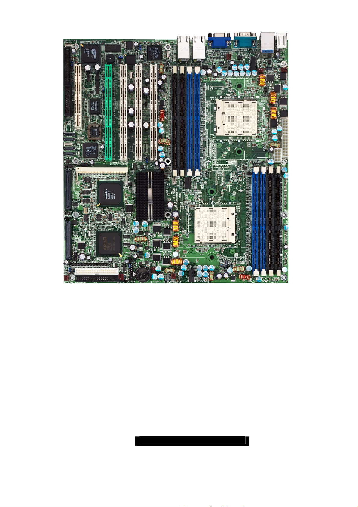
2.00 – Board Image
This picture is representative of the latest board revision available at the time of
publishing. The board you receive may or may not look exactly like the above
picture.
The following page includes details on the vital components of this motherboard.
8
http://www.TYAN.com
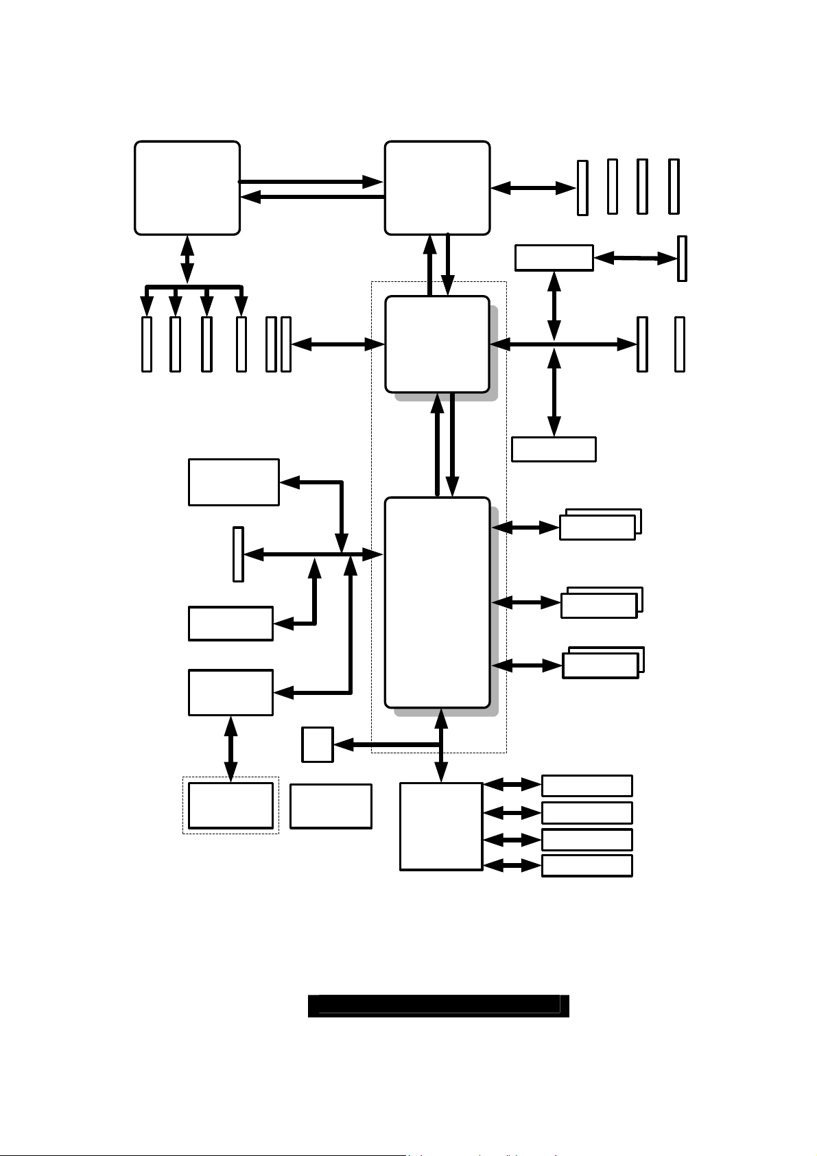
2.01
Block Diagram
–
Thunder K8S Pro S2882 Block Diagram
Processor
200-333MHz
184 pin
184 pin
DIMM2
DIMM3
AMD
Opteron
TM
144Bit
184 pin
DIMM1
Intel-82551
10/100
(Optional)
LINK 0B
16x16 Hyper Transport@1600MT/s
OUT
IN
16x16 Hyper Transport@1600MT/s
PCI-X Slots
64-Bit/133/100MHz
184 pin
DIMM0
8x8 ncHyper Transport@400MT/s
AMD
Opteron
Processor
IN
LINK 0A
AMD
AMD-8131
IN OUT
LINK 1
TM
OUT
AMD Chipset
200-333MT/s
144-Bit
Adapte c
AIC-7902 SCSI
BCM5704C
Gigabit LAN
184 pin
184 pin
DIMM0
DIMM1
64-Bit/100/66MHz
PCI-X Slot
*ZCR support with Adaptec
PCI or SO-DIMM ZCR card
(Optional)
184 pin
184 pin
DIMM2
DIMM3
SO-DIMM144
(ZCR)
PCI-X Slot
(PCI4 / ZCR)
PCI
Slot
ATI RAGE XL
8MB
Silicon Image
SiI3114
4 X Serial ATA
RAID Ports
150MB/s
32-Bit/33MHz
LPC
ROM
ADM1027
Hardware
monitor
AMD
AMD-8111
Winbond
W83627F/HF
LPC Super I/O
LPC
EIDE(ATA/133) x2
USB 1.1 x 2
USB Ports: 2 to backplane
USB 1.1 x2
2 to header
Floppy Disk Drive
PS/2 Keyboard &
Mouse
Parallel Port x 1
Serial Port x 2
9
http://www.TYAN.com

2.02 – Board Parts, Jumpers and Connectors
SATA1
SATA2
SATA3
SATA4
J23
1
LAN1/2
ATI
RAGE XL
1
FDD
J46
LPT1
PCI5
COM2
1
J61
SCSI-A SCSI-B
1
KEYLOCK
W83627HF
Winbond
BIOS
CH-A
J43
1
J41
ZCR J22
1
J60
Bz1
LAN3
PCIX-A
PCI4 PCI3 PCI2 PCI1
(Optional)
PCIX-A
1
J52
J39
1
PCIX-B
PCIX-B
J24
CH-B
LAN1
J58
J50
LAN2
J56 (VGA)
J48
1
FAN 2
CPU2
J57 (COM1)
USB1 (Bottom)
LAN3 (Top)Optional
J54
USB1
1
J47
CPU2_FAN
KB(Bottom)
Mouse(Top)
KB-MS
J44
J25
J55
1
FAN 1
J29
J19
J17
FAN5
J3
1
1
CMOS
1
INTRUDER
LAN3_LED
1
J8
1
USB2
J12
AMD-8111
SMDC
PRI-IDE
SEC-IDE
SCSI
7902
AMD
J11
1
1
J6
J45
J4
FAN3
1
1
J1
AMD-8131
BT1
1
LAN1_LED
AMD
J9
FAN4
1
1
J2
LAN2_LED
1
J5
CPU1_FAN
CPU1
This diagram is representative of the latest board revision available at the time of
publishing. The board you receive may not look exactly like the above diagram.
10
http://www.TYAN.com
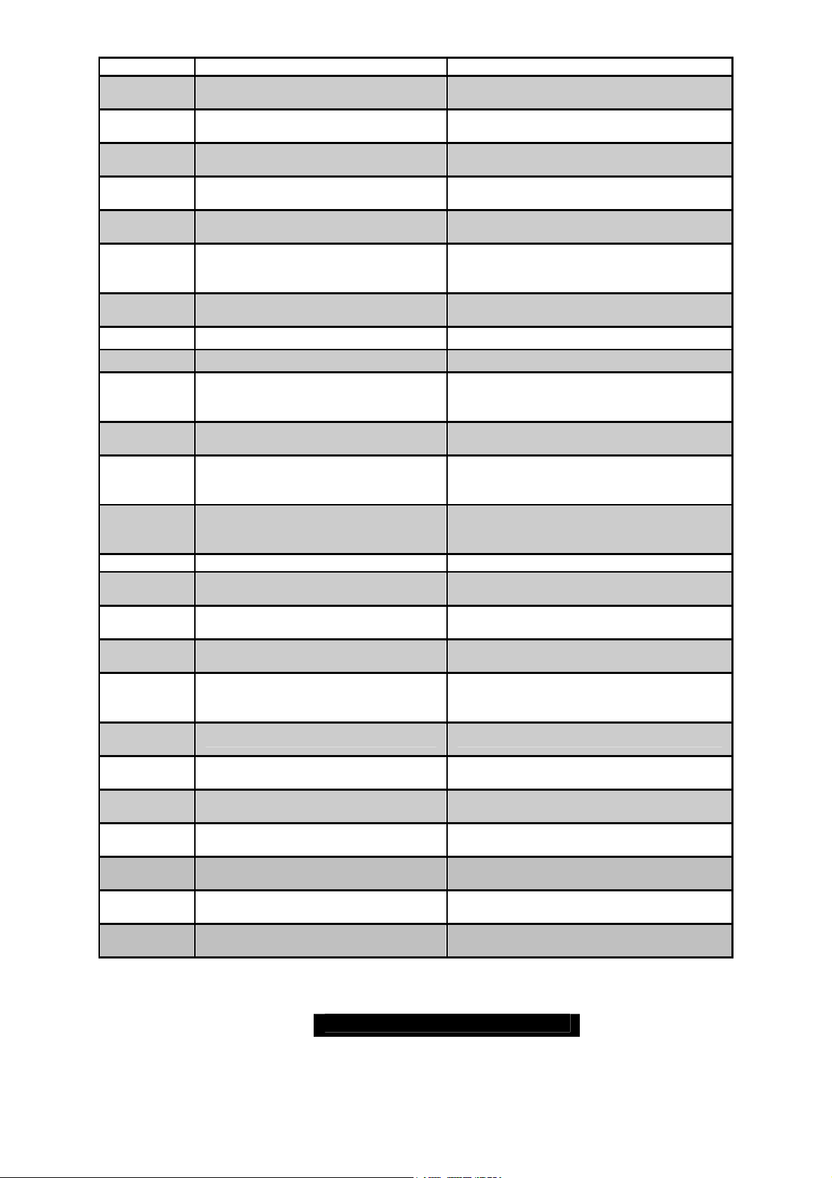
Jumper Function Settings
J1 / J2
J6
Gigabit Ethernet LAN_1 &
LAN_2 Front Panel LED Header
Front Panel Connector
J8 Clear CMOS Jumper
J11 SMBus_0 Connector
J12
J17
J19
J22
J23
J24 / J39
J41
J42
KEYLOCK
USB Connector header
10/100 Ethernet LAN3
Front Panel LED Header
Chassis Intrusion Connector
SO-DIMM Socket See Section 2.10
COM2 Header See Section 2.11 for pinout
PCI-X Bridge B (PCI 1 & PCI 2)
PCI-X Speed Select Jumper
PCI-X Bridge A (PCI3 & PCI4)
force PCI Mode Jumper
Keylock Enable/Disable Jumper
PCI-X Bridge A (PCI 3 & PCI 4 &
J43
SCSI7902 & BCM5704) PCI-X
Speed Select Jumper
See Section 2.03 for pinout
configuration
See Section 2.04 for pinout
configuration
1-2 Close:
2-3 Close: Clear CMOS mode
Normal mode (Default)
See section 2.06 for pinout
configuration
For front or rear chassis mount USB
connectors
See Section 2.08 for pinout
configuration
See Section 2.09 for pinout
configuration
133MHz: J24 & J39 open (Default)
100MHz: J24 close; J39 open
66MHz: J24 & J39 close
Open
: PCI-X mode (Default)
Close: PCI mode
Open: Enable PS/2 keyboard
(Default)
Close: Disable PS/2 keyboard
Open: up to PCI-X 100MHz (Default)
Close: PCI-X 66MHz
J45 SMDC Connector See Appendix II SMDC information
J46
J52
J60
J61
(Optional)
P1_FAN
(J5)
P2_FAN
(J47)
FAN1
(J44)
FAN2
(J48)
FAN3
(J4)
FAN4
(J9)
FAN5
(J3)
Onboard VGA Enable/Disable
Jumper
Onboard Gigabit Ethernet
Enable/Disable Jumper
Onboard 10/100 Ethernet
Enable/Disable Jumper
ZCR Card Connector Select
Enable/Disable Jumper
CPU_1 Fan Connector With speed, MAX 2.0A
CPU_2 Fan Connector With speed, MAX 2.0A
Chassis Fan Connector With speed control, MAX 3.0A
Chassis Fan Connector With speed control, MAX 2.0A
Chassis Fan Connector With speed control, MAX 3.0A
Chassis Fan Connector With speed, MAX 2.0A
Chassis Fan Connector With speed, MAX 2.0A
1-2 Close: Enable (Default)
2-3 Close: Disable
Open: Disable
Close: Enable (Default)
1-2 Close: Enable (Default)
2-3 Close: Disable
1-2 Close: PCI4 slot Enable
2-3 Close
Enable (Default)
: SO-DIMM Connector
11
http://www.TYAN.com
Jumper Legend
)
)
)
OPEN - Jumper OFF without jumper
CLOSED - Jumper ON with jumper
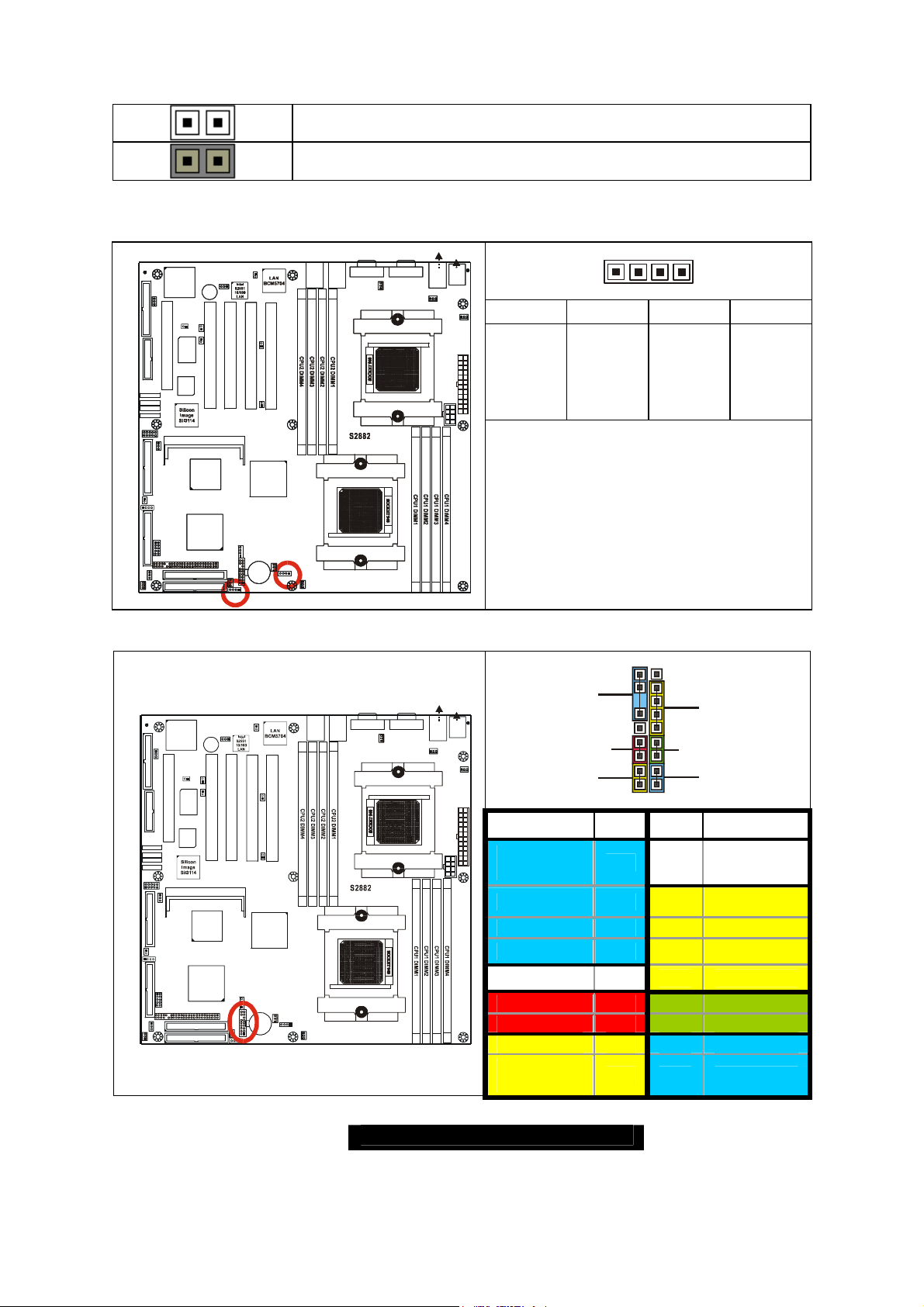
2.03 –Gigabit LAN_1 Front Panel LED Header (J1) and
Gigabit LAN_2 Front Panel LED Header (J2)
LAN1/2
LAN1/2
1
1
(Optional)
J60
J60
Bz1
Bz1
LAN3
LAN3
CH-A
CH-A
J43
J43
1
1
1
1
Winbond
Winbond
J41
J41
PCIX-A
PCIX-A
PCI4 PCI3 PCI2 PCI1
PCI4 PCI3 PCI2 PCI1
ZCR J22
ZCR J22
SCSI
SCSI
7902
7902
AMD
AMD
AMD-8111
AMD-8111
1
1
J45
J45
PRI-IDE
PRI-IDE
SEC-IDE
SEC-IDE
1
1
PCIX-A
PCIX-A
J4
J4
FAN3
FAN3
J1
J1
(Optional)
J11
J11
1
1
J6
J6
1
1
1
1
LAN1_LED
LAN1_LED
1
1
J52
J52
PCIX-B
PCIX-B
J39
J39
1
1
J24
J24
CH-B
CH-B
AMD
AMD
AMD-8131
AMD-8131
BT1
BT1
ATI
ATI
RAGE XL
RAGE XL
1
1
FDD
FDD
J46
J46
KEYLOCK
KEYLOCK
W83627HF
W83627HF
LPT1
LPT1
PCI5
PCI5
BIOS
BIOS
SATA1
SATA1
SATA2
SATA2
SATA3
SATA3
SATA4
SATA4
J23
J23
COM2
COM2
1
1
1
1
J61
J61
SCSI-A SCSI -B
SCSI-A SCSI -B
1
1
J19
J19
INTRUDER
INTRUDER
1
1
LAN3_LED
LAN3_LED
J17
J17
1
1
USB2
USB2
J12
J12
SMDC
SMDC
CMOS
CMOS
1
1
J8
J8
J3
J3
FAN5
FAN5
1
1
J58
J58
J50
J50
LAN1
LAN1
LAN2
LAN2
PCIX-B
PCIX-B
CPU1
J9
J9
FAN4
FAN4
1
1
1
1
LAN2_LED
LAN2_LED
1
1
J2
J2
J5
J5
CPU1_FAN
CPU1_FAN
CPU1
USB1 (Bottom
USB1 (Bottom
LAN3 (Top)Optional
LAN3 (Top)Optional
KB(Bottom)
KB(Bottom)
Mouse(Top)
Mouse(Top)
J55
J54
J57 (COM1)J56 (VGA)
J57 (COM1)J56 (VGA)
J48
J48
1
1
FAN 2
FAN 2
CPU2
CPU2
J54
USB1
USB1
1
1
CPU2_FAN
CPU2_FAN
J55
KB-MS
KB-MS
J47
J47
1
1
J44
J44
J25
J25
Pin_4 Pin_3 Pin_2 Pin_1
FAN 1
FAN 1
J29
J29
Green -
Green LED solid= 10Mb link
Green LED flashing= 10Mb activity
Yellow LED solid= 100Mb link
Yellow LED flashing= 100Mb activity
Both LED Solid= Gigabit link
Both LED flashing= Gigabit activity
14
Green +
Yellow -
Yellow +
2.04 – Front Panel Connector (J6)
LAN1/2
ATI
RAGE XL
1
FDD
J46
CH-A
J43
1
KEYLOCK
1
W83627HF
Winbond
PCI5
COM2
1
J61
INTRUDER
LAN3_LED
1
USB2
J12
J8
BIOS
SMDC
PRI-IDE
SEC-IDE
J41
ZCR J22
SCSI
7902
AMD
AMD-8111
LPT1
SATA1
SATA2
SATA3
SATA4
J23
1
SCSI-A SCSI-B
1
J19
1
J17
CMOS
1
J3
1
FAN5
1
(Optional)
J52
1
J60
Bz1
LAN3
J39
PCIX-A
PCI4 PCI3 PCI2 PCI1
1
PCIX-A
PCIX-B
J24
CH-B
AMD
AMD-8131
J11
1
1
J6
J45
BT1
J4
FAN3
1
1
LAN1_LED
1
J1
PCIX-B
J9
FAN4
1
J2
1
LAN2_LED
LAN1
1
J5
CPU1_FAN
J50
J58
LAN2
CPU1
18 17
USB1 (Bottom
LAN3 (Top)Optional
KB(Bottom)
Mouse(Top )
J55
J54
J57 (COM1)J56 (VGA)
J48
1
FAN 2
USB1
1
CPU2_FAN
KB-MS
J47
1
J44
FAN 1
J29
SPEAKER /
BUZZER
POWER
PWR-LED
2 1
INFRARED
RESET
HD-LED
Function PIN PIN Function
CPU2
J25
Speaker- /
Buzzer-
Buzzer+
NONE
18 17 NC
16 15
14 13
IRTX
GND
Speaker+ 12 11 IRRX
NC
GND
PWR+
Power LED-
Power
LED+
10
8 7
6 5
4 3
2 1
9
+5V
Reset SW+
GND
HDD LED-
HDD LED+
12
http://www.TYAN.com
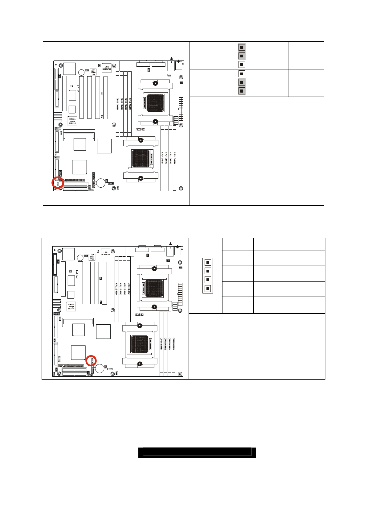
2.05 – Clear CMOS Jumper (J8)
)
LAN1/2
1
J60
Bz1
LAN3
CH-A
1
J43
1
Winbond
J41
PCIX-A
PCI4 PCI3 PC I2 PCI1
ZCR J22
SCSI
7902
AMD
AMD-8111
1
J45
PRI-IDE
SEC-IDE
1
(Optional)
PCIX-A
J11
J4
FAN3
J1
J6
1
1
LAN1_LED
1
J52
J39
1
PCIX-B
J24
CH-B
AMD
AMD-8131
BT1
1
ATI
RAGE XL
1
FDD
J46
KEYLOCK
W83627HF
LPT1
PCI5
BIOS
SATA1
SATA2
SATA3
SATA4
J23
COM2
1
1
J61
SCSI-A SCSI-B
1
J19
INTRUDER
1
LAN3_LED
J17
1
USB2
J12
SMDC
CMOS
1
J8
J3
1
FAN5
J58
J50
LAN1
LAN2
PCIX-B
J9
FAN4
1
1
LAN2_LED
1
J2
J5
CPU1_FAN
2.06 – SMBus_0 Connector (J11)
LAN1/2
ATI
RAGE XL
1
FDD
J46
CH-A
1
J43
KEYLOCK
1
W83627HF
Winbond
PCI5
COM2
1
J61
INTRUDER
LAN3_LED
1
USB2
J12
J8
BIOS
SMDC
PRI-IDE
SEC-IDE
J41
ZCR J22
SCSI
7902
AMD
AMD-8111
LPT1
SATA1
SATA2
SATA3
SATA4
J23
1
SCSI-A SCSI-B
1
J19
1
J17
CMOS
1
J3
1
FAN5
1
(Optional)
J52
1
J60
Bz1
LAN3
J39
PCIX-A
PCI4 PCI3 PCI2 PCI1
1
PCIX-A
PCIX-B
J24
CH-B
AMD-8131
J11
1
1
J6
J45
BT1
J4
FAN3
1
1
LAN1_LED
1
J1
AMD
J58
J50
LAN1
LAN2
PCIX-B
J5
CPU1_FAN
CPU1
J9
FAN4
1
1
LAN2_LED
1
J2
CPU1
USB1 (Bott om)
LAN3 (Top)Optional
KB(Bottom )
Mouse(Top)
J55
J54
J57 (COM1)J56 (VGA)
J48
1
FAN 2
USB1
1
CPU2_FAN
KB-MS
J47
1
J44
FAN 1
J29
1
Default
3
1
Clear
3
You can reset the CMOS settings by
CPU2
J25
using this jumper if you have forgotten
your system/setup password or need to
clear system BIOS setting.
-
Power off system and disconnect
both power connectors from the
motherboard
-
Use jumper cap to close Pin_2 and
Pin_3 for several seconds to Clear
CMOS
-
Put jumper cap back to Pin_1 and
Pin_2 (default setting)
Reconnect power & power on system
USB1 (Bottom
LAN3 (Top)Optional
KB(Bottom)
Mouse(Top)
J55
J54
J57 (COM1)J56 (VGA)
J48
1
FAN 2
USB1
1
CPU2_FAN
KB-MS
J47
1
J44
FAN 1
J29
4
1
CPU2
J25
Pin # Signal Description
4
NC
3 SMBUS_CLK
2 GND
1
SMBUS_DATA
Use this connector to connect external
SMBUS devices
13
http://www.TYAN.com
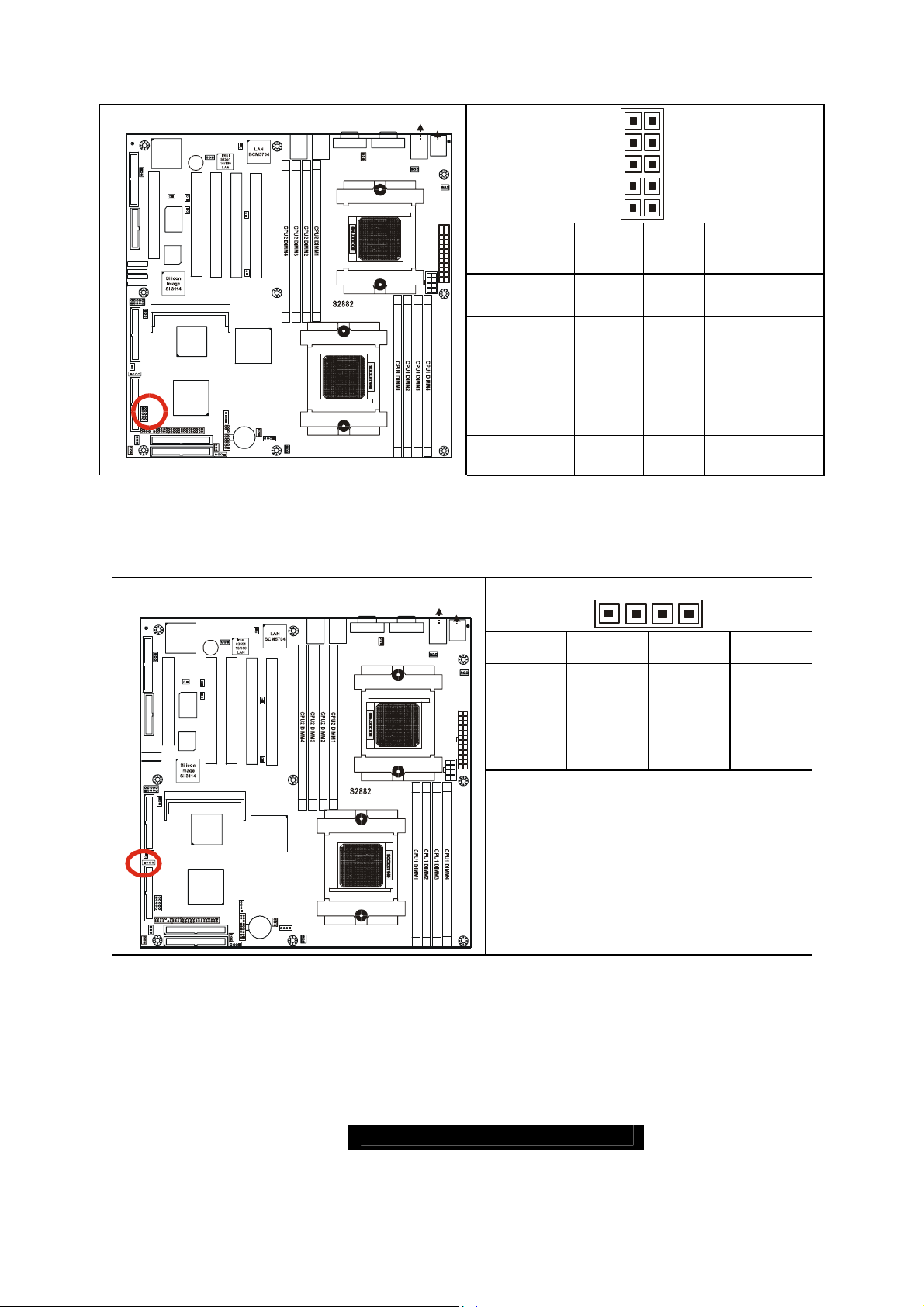
2.07 – USB Connector Headers (J12)
)
USB1 (Bott om)
LAN3 (Top)Optional
KB(Bottom)
LAN1/2
ATI
RAGE XL
1
FDD
J46
CH-A
J43
1
KEYLOCK
1
W83627HF
Winbond
COM2
1
J61
INTRUDER
LAN3_LED
1
USB2
J12
J8
J41
PCI5
BIOS
ZCR J22
SCSI
7902
AMD
AMD-8111
SMDC
PRI-IDE
SEC-IDE
LPT1
SATA1
SATA2
SATA3
SATA4
J23
1
SCSI-A SCSI-B
1
J19
1
J17
CMOS
1
J3
1
FAN5
1
(Optional)
J52
1
J60
Bz1
LAN3
J39
PCIX-A
PCI4 PCI3 PCI2 PCI1
1
PCIX-A
PCIX-B
J24
CH-B
AMD
AMD-8131
J11
1
1
J6
J45
BT1
J4
FAN3
1
1
LAN1_LED
1
J1
PCIX-B
J9
FAN4
1
J2
1
LAN2_LED
LAN1
1
J5
CPU1_FAN
J50
J58
LAN2
CPU1
J57 (COM1)J56 (VGA)
J48
1
FAN 2
CPU2
J54
USB1
1
CPU2_FAN
Mouse(Top)
J55
KB-MS
J47
1
J44
FAN 1
J29
Signal
J25
Description
+5V
Data -
Data + 5 6 Data +
GND
GND
2.08 – 10/100 LAN Front Panel LED Header (J17)
1
FDD
J46
LPT1
ATI
RAGE XL
KEYLOCK
LAN1/2
1
(Optiona l)
J52
1
J60
Bz1
LAN3
CH-A
1
J43
1
W83627HF
Winbond
J41
PCIX-A
J39
1
PCIX-A
PCIX-B
J58
J50
LAN1
LAN2
PCIX-B
USB1 (Bottom
LAN3 (Top)Optional
KB(Bottom)
Mouse(Top)
J55
J54
J57 (COM1)J56 (VGA)
J48
1
FAN 2
USB1
1
CPU2_FAN
KB-MS
J47
1
J44
FAN 1
J29
1
9
Pin # Pin #
1 2
3 4
7 8
9 10
2
10
Signal
Description
+5V
Data -
GND
GND
41
Pin_1 Pin_2 Pin_3 Pin_4
Yellow +
Yellow -
Green +
Green -
PCI5
BIOS
SATA1
SATA2
SATA3
SATA4
J23
1
1
J61
SCSI-A SCSI- B
1
J19
INTRUDER
1
LAN3_LED
J17
1
CMOS
1
J8
J3
1
FAN5
COM2
USB2
J12
PCI4 PCI3 PCI2 PCI1
ZCR J22
SCSI
7902
AMD
AMD-81 11
SMDC
PRI-IDE
SEC-ID E
J24
CH-B
AMD
AMD-8131
CPU2
J25
Green LED solid= 10Mb link
Green LED flashing= 10Mb activity
Yellow LED solid= 100Mb link
J11
J9
1
1
J45
FAN4
J6
BT1
J4
FAN3
1
LAN1_LED
1
J1
1
1
LAN2_LED
1
J2
1
J5
CPU1_FAN
CPU1
Yellow LED flashing= 100Mb activity
14
http://www.TYAN.com

2.09 – Chassis Intrusion Connector (J19)
)
LAN1/2
ATI
RAGE XL
1
FDD
J46
CH-A
J43
1
KEYLOCK
1
W83627HF
Winbond
PCI5
COM2
1
J61
INTRUDER
LAN3_LED
1
USB2
J12
J8
BIOS
SMDC
PRI-IDE
SEC-IDE
J41
ZCR J22
SCSI
7902
AMD
AMD-8111
LPT1
SATA1
SATA2
SATA3
SATA4
J23
1
SCSI-A SC SI-B
1
J19
1
J17
CMOS
1
J3
1
FAN5
1
(Optional)
J52
1
J60
Bz1
LAN3
J39
PCIX-A
PCI4 PCI3 PCI2 PCI1
1
PCIX-A
PCIX-B
J24
CH-B
AMD-8131
J11
1
1
J6
J45
BT1
J4
FAN3
1
1
LAN1_LED
1
J1
PCIX-B
AMD
J9
FAN4
1
J2
1
LAN2_LED
1
J5
CPU1_FAN
J50
J58
LAN2
LAN1
J57 (COM1)J56 (VGA)
J48
1
FAN 2
CPU2
CPU1
2.10 – SO-DIMM Socket (J22)
LAN1/2
1
ATI
RAGE XL
1
FDD
J46
KEYLOCK
W83627HF
LPT1
(Optiona l)
J52
1
J60
Bz1
LAN3
CH-A
J43
1
1
Winbond
J41
PCIX-A
J39
1
PCIX-A
PCIX-B
J58
J50
LAN1
LAN2
PCIX-B
USB1 (Bott om)
LAN3 (Top)Optional
J57 (COM1)J56 (VGA)
J48
1
FAN 2
USB1 (Bottom
LAN3 (Top)Optional
J54
USB1
1
CPU2_FAN
J54
USB1
1
J47
CPU2_FAN
KB(Bottom)
Mouse(Top)
J55
KB-MS
J47
1
J44
FAN 1
Pin-1
J29
1
Intrusion detection
Pin-2
J25
GND
For use with chassis that support
this feature
KB(Bottom )
Mouse(Top)
J55
This socket is capable of accepting the
KB-MS
Adaptec Zero Channel RAID card.
1
J44
Compatible with Adaptec ASR-2015S
FAN 1
(ZCR)
J29
PCI5
BIOS
SATA1
SATA2
SATA3
SATA4
J23
1
1
J61
SCSI-A SC SI-B
1
J19
INTRUDER
1
LAN3_LED
J17
1
CMOS
1
J8
J3
1
FAN5
COM2
USB2
J12
PCI4 PCI3 PCI2 PCI1
ZCR J22
SCSI
7902
AMD
AMD-8111
SMDC
PRI-IDE
SEC-IDE
J24
CH-B
AMD
AMD-8131
J11
J9
1
1
J45
FAN4
J6
BT1
J4
FAN3
1
LAN1_LED
1
J1
1
1
LAN2_LED
1
J2
1
J5
CPU1_FAN
CPU2
CPU1
J25
15
http://www.TYAN.com
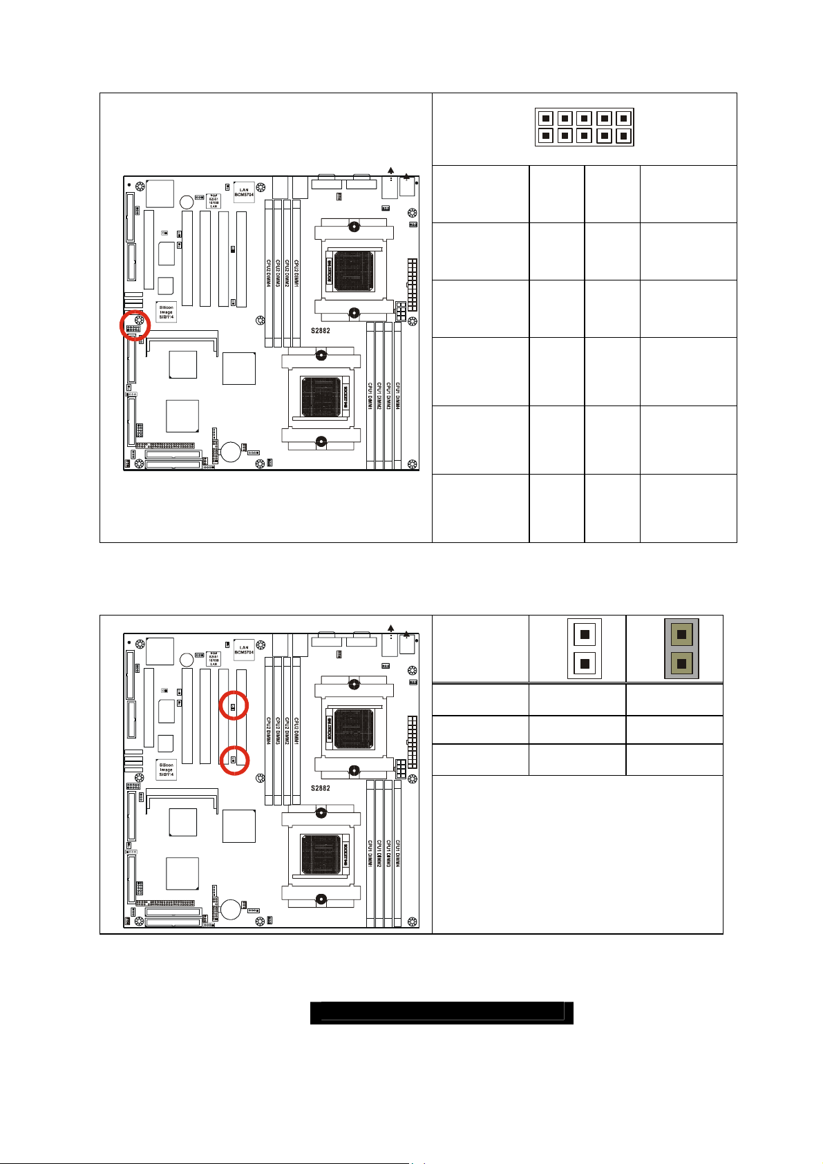
2.11 – COM2 Header (J23)
)
)
2 10
USB1 (Bottom
LAN3 (Top)Optional
KB(Bottom)
LAN1/2
ATI
RAGE XL
1
FDD
J46
CH-A
J43
1
KEYLOCK
1
W83627HF
Winbond
PCI5
COM2
1
J61
INTRUDER
LAN3_LED
1
USB2
J12
J8
BIOS
SMDC
PRI-IDE
SEC-IDE
J41
ZCR J22
SCSI
7902
AMD
AMD-8111
LPT1
SATA1
SATA2
SATA3
SATA4
J23
1
SCSI-A SC SI-B
1
J19
1
J17
CMOS
1
J3
1
FAN5
1
(Optional)
J52
1
J60
Bz1
LAN3
J39
PCIX-A
PCI4 PCI3 PCI2 PCI1
1
PCIX-A
PCIX-B
J24
CH-B
AMD-8131
J11
1
1
J6
J45
BT1
J4
FAN3
1
1
LAN1_LED
1
J1
PCIX-B
AMD
J9
FAN4
1
J2
1
LAN2_LED
1
J5
CPU1_FAN
J50
J58
LAN2
LAN1
CPU1
J57 (COM1)J56 (VGA)
J48
1
FAN 2
CPU2
J54
USB1
1
CPU2_FAN
Mouse(Top)
J55
1
FAN 1
J29
Signal
Description
NC/KEY
RI (Ring-
KB-MS
J47
J44
J25
Indicator)
CTS (Clearto-Send)
RTS
(Requestto-Send)
DSR (DataSet-Ready)
1 9
Pin# Pin#
10 9
8 7
6 5
4 3
2 1
2.12 – PCI-X Bridge B (PCI 1 & PCI 2) PCI-X Speed Select Jumper (J24 / J39)
LAN1/2
1
J60
Bz1
LAN3
CH-A
1
J43
1
Winbond
J41
PCIX-A
PCI4 PCI3 PCI2 PCI1
ZCR J22
SCSI
7902
AMD
AMD-8111
1
J45
PRI-IDE
SEC-IDE
1
PCIX-A
J4
FAN3
J1
(Optional)
J11
1
J6
1
1
LAN1_LED
1
J52
PCIX-B
J39
1
J24
CH-B
AMD
AMD-8131
BT1
PCIX-B
J9
FAN4
1
J2
ATI
RAGE XL
1
FDD
J46
KEYLOCK
W83627HF
LPT1
PCI5
BIOS
SATA1
SATA2
SATA3
SATA4
J23
COM2
1
1
J61
SCSI-A SC SI-B
1
J19
INTRUDER
1
LAN3_LED
J17
1
USB2
J12
SMDC
CMOS
1
J8
J3
1
FAN5
1
LAN2_LED
1
J5
CPU1_FAN
J50
J58
LAN2
LAN1
CPU1
USB1 (Bottom
LAN3 (Top)Optional
KB(Bottom)
Mouse(Top)
J55
J54
J57 (COM1)J56 (VGA)
J48
1
FAN 2
USB1
1
CPU2_FAN
KB-MS
J47
1
J44
FAN 1
J29
Speed
1
133MHz J24 / J39
100MHz J39 J24
CPU2
J25
66MHz J24 / J39
Allows PCI-X Bridge B to operate at up
to 133MHz (For use with one PCI-X
133 device)
Tyan recommends using PCI-X Slot
1 for 133MHz support
Signal
Description
GND
(Ground)
DTR (DataTerminalReady)
TX
(TransferData)
RX
(ReceiveData)
DCD
(Data
Carrier
Detect)
1
16
http://www.TYAN.com
2.13 – PCI-X Bridge A (PCI 3 & PCI 4) force PCI Mode Jumper (J41)
)
)
USB1 (Bottom
LAN3 (Top)Optional
KB(Bottom)
LAN1/2
1
J60
Bz1
LAN3
CH-A
1
J43
1
Winbond
J41
PCIX-A
PCI4 PCI3 PCI2 PCI1
ZCR J22
SCSI
7902
AMD
AMD-8111
1
J45
PRI-IDE
SEC-IDE
1
PCIX-A
J4
FAN3
J1
(Optional)
J11
1
J6
1
1
LAN1_LED
1
J52
PCIX-B
J39
1
J24
CH-B
AMD
AMD-8131
BT1
PCIX-B
J9
FAN4
1
J2
ATI
RAGE XL
1
FDD
J46
KEYLOCK
W83627HF
LPT1
PCI5
BIOS
SATA1
SATA2
SATA3
SATA4
J23
COM2
1
1
J61
SCSI-A SC SI-B
1
J19
INTRUDER
1
LAN3_LED
J17
1
USB2
J12
SMDC
CMOS
1
J8
J3
1
FAN5
1
LAN2_LED
1
J5
CPU1_FAN
J50
J58
LAN2
LAN1
CPU1
J57 (COM1)J56 (VGA)
J48
1
FAN 2
CPU2
J54
USB1
1
CPU2_FAN
Mouse(Top)
KB-MS
J47
J44
J25
2.14 – Keylock Enable/Disable Jumper (J42)
USB1 (Bottom
LAN3 (Top)Optional
KB(Bottom)
LAN1/2
1
ATI
RAGE XL
1
FDD
J46
KEYLOCK
W83627HF
LPT1
(Optional)
J52
1
J60
Bz1
LAN3
CH-A
1
J43
1
Winbond
J41
PCIX-A
J39
1
PCIX-A
PCIX-B
PCIX-B
J50
J58
LAN2
LAN1
J57 (COM1)J56 (VGA)
J48
1
FAN 2
J54
USB1
1
CPU2_FAN
Mouse(Top)
KB-MS
J47
J44
1
J55
1
OPEN
FAN 1
Allows PCI 3 and PCI 4 to operate in
J29
PCI-X Mode
(Default)
1
CLOSED
To force PCI 3 and PCI 4 to operate in
PCI compatible mode. Close this
jumper if the card you are using does
not support PCI-X.
1
J55
1
OPEN
FAN 1
Enable PS/2 keyboard
J29
(Default)
PCI5
BIOS
SATA1
SATA2
SATA3
SATA4
J23
COM2
1
1
J61
SCSI-A SC SI-B
1
J19
INTRUDER
1
LAN3_LED
J17
1
CMOS
1
J8
J3
1
FAN5
USB2
J12
PCI4 PCI3 PCI2 PCI1
ZCR J22
SCSI
7902
AMD
AMD-8111
SMDC
PRI-IDE
SEC-IDE
J24
CH-B
CPU2
J25
1
AMD
AMD-8131
CLOSED
J11
J9
1
1
J45
FAN4
J6
BT1
J4
FAN3
1
LAN1_LED
1
J1
1
1
LAN2_LED
1
J2
1
J5
CPU1_FAN
CPU1
Disable PS/2 keyboard
17
http://www.TYAN.com
2.15 – PCI-X Bridge A (PCI 3 & PCI 4 & SCSI7902 & BCM5704) PCI-X Speed Select
)
Jumper (J43)
USB1 (Bottom
LAN3 (Top)Optional
KB(Bottom)
LAN1/2
1
ATI
RAGE XL
1
FDD
J46
KEYLOCK
W83627HF
LPT1
(Optional)
J52
1
J60
Bz1
LAN3
CH-A
1
J43
1
Winbond
J41
PCIX-A
J39
1
PCIX-A
PCIX-B
PCIX-B
J50
J58
LAN2
LAN1
J57 (COM1)J56 (VGA)
J48
1
FAN 2
J54
USB1
1
CPU2_FAN
Mouse(Top)
J55
KB-MS
J47
J44
OPEN (Default)
1
Allows PCI-X Bridge A (PCI 3 & PCI 4
FAN 1
& SCSI7902 & BCM5704) to operate
J29
at up to 100MHz
PCI5
BIOS
SATA1
SATA2
SATA3
SATA4
J23
COM2
1
1
J61
SCSI-A SC SI-B
1
J19
INTRUDER
1
LAN3_LED
J17
1
CMOS
1
J8
J3
1
FAN5
USB2
J12
PCI4 PCI3 PCI2 PCI1
ZCR J22
SCSI
7902
AMD
AMD-8111
SMDC
PRI-IDE
SEC-IDE
J24
CH-B
AMD
AMD-8131
CPU2
J25
CLOSED
Sets PCI-X Bridge A (PCI 3 & PCI 4 &
SCSI7902 & BCM5704) to operate at
a maximum 66MHz
J11
J9
1
1
J45
FAN4
J6
BT1
J4
FAN3
1
LAN1_LED
1
J1
1
1
LAN2_LED
1
J2
1
J5
CPU1_FAN
CPU1
Note
: Due to the PCI-X specifications
it will be necessary to set this bus to
1
1
66MHz if a 133/100MHz PCI-X card is
added to this bus.
2.16 –SMDC Connector (J45)
LAN1/2
1
ATI
RAGE XL
1
FDD
J46
KEYLOCK
W83627HF
LPT1
(Optiona l)
J52
1
J60
Bz1
LAN3
CH-A
1
J43
1
Winbond
J41
PCIX-A
J39
1
PCIX-A
PCIX-B
J58
J50
LAN1
LAN2
PCIX-B
USB1 (Bott om)
LAN3 (Top)Optional
KB(Bottom )
Mouse(Top)
Connect Server Management Daughter
J55
J54
J57 (COM1)J56 (VGA)
USB1
J48
1
FAN 2
1
J47
CPU2_FAN
Card (SMDC) (Ref. Appendix II)
KB-MS
Compatible with Tyan M3289 (SMDC)
1
J44
FAN 1
J29
PCI5
BIOS
SATA1
SATA2
SATA3
SATA4
J23
1
1
J61
SCSI-A SCSI-B
1
J19
INTRUDER
1
LAN3_LED
J17
1
CMOS
1
J8
J3
1
FAN5
COM2
USB2
J12
PCI4 PCI3 PCI2 PCI1
ZCR J22
SCSI
7902
AMD
AMD-8111
SMDC
PRI-IDE
SEC-IDE
J24
CH-B
AMD
AMD-8131
J11
J9
1
1
J45
FAN4
J6
BT1
J4
FAN3
1
LAN1_LED
1
J1
1
1
LAN2_LED
1
J2
1
J5
CPU1_FAN
CPU2
CPU1
J25
18
http://www.TYAN.com
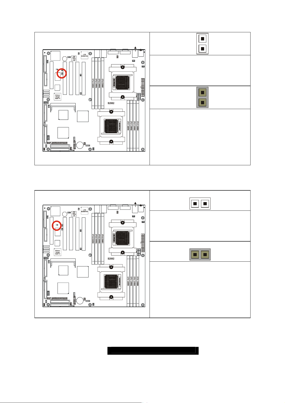
2.17 – Onboard VGA Enable/Disable Jumper (J46)
)
LAN1/2
ATI
RAGE XL
1
FDD
J46
CH-A
J43
1
KEYLOCK
1
W83627HF
Winbon d
PCI5
COM2
1
J61
INTRUDER
LAN3_LED
1
USB2
J12
J8
BIOS
SMDC
PRI-IDE
SEC-IDE
J41
ZCR J22
SCSI
7902
AMD
AMD-8111
LPT1
SATA1
SATA2
SATA3
SATA4
J23
1
SCSI-A SCSI- B
1
J19
1
J17
CMOS
1
J3
1
FAN5
1
(Optional)
J52
1
J60
Bz1
LAN3
J39
PCIX-A
PCI4 PCI3 PCI2 PCI1
1
PCIX-A
PCIX-B
J24
CH-B
AMD
AMD-8131
J11
1
1
J6
J45
BT1
J4
FAN3
1
1
LAN1_LED
1
J1
PCIX-B
J9
FAN4
1
J2
1
LAN2_LED
1
J5
CPU1_FAN
J50
J58
LAN2
LAN1
CPU1
USB1 (Bottom
LAN3 (Top)Optional
KB(Bottom)
Mouse(Top)
J55
J54
J57 (COM1)J56 (VGA)
J48
1
FAN 2
USB1
1
CPU2_FAN
KB-MS
J47
1
J44
FAN 1
CLOSED: 1 - 2 (Default)
J29
To enable onboard ATI Rage XL
Graphic chip
CPU2
J25
1
3
1
3
CLOSED: 2 - 3
To disable onboard ATI Rage XL
Graphic chip
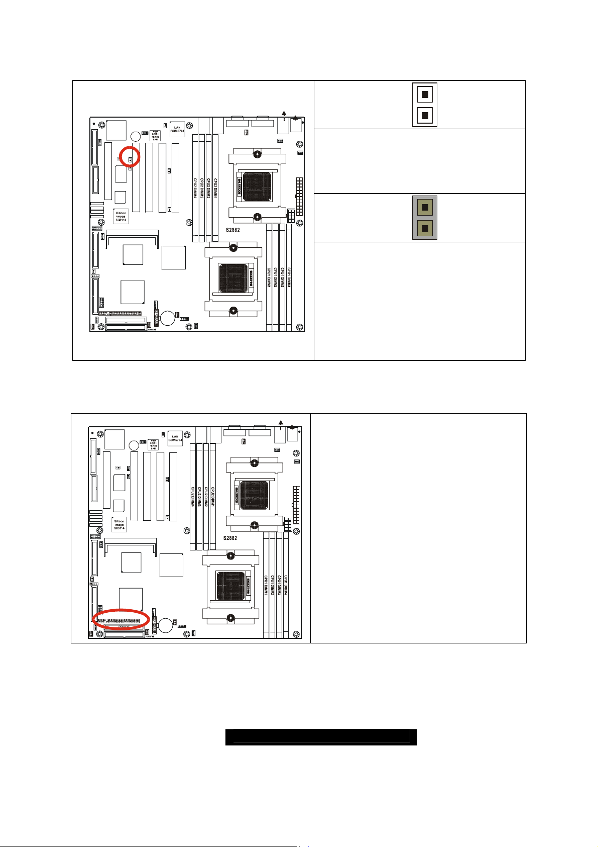
2.18 – Onboard Gigabit Ethernet Enable/Disable Jumper (J52)
LAN1/2
1
ATI
RAGE XL
1
FDD
J46
KEYLOCK
W83627HF
LPT1
(Optional)
J52
1
J60
Bz1
LAN3
CH-A
J43
1
1
Winbond
J41
PCIX-A
J39
1
PCIX-A
PCIX-B
J58
J50
LAN1
LAN2
PCIX-B
USB1 (Bott om)
LAN3 (Top)Optional
KB(Bottom)
J57 (COM1)J56 (VGA)
J48
1
FAN 2
USB1
1
CPU2_FAN
KB-MS
J47
1
J44
FAN 1
J29
OPEN
Mouse(Top)
J55
J54
1
To disable onboard Gigabit Ethernet
PCI5
BIOS
SATA1
SATA2
SATA3
SATA4
J23
1
1
J61
SCSI-A SCSI- B
1
J19
INTRUDER
1
LAN3_LED
J17
1
CMOS
1
J8
J3
1
FAN5
COM2
USB2
J12
PCI4 PCI3 PCI 2 PC I1
ZCR J22
SCSI
7902
AMD
AMD-8111
SMDC
PRI-IDE
SEC-IDE
J24
CH-B
AMD
AMD-8131
J11
J9
1
1
J45
FAN4
J6
BT1
1
LAN1_LED
1
1
LAN2_LED
1
J2
J5
CPU1_FAN
J4
FAN3
1
1
J1
CPU2
CPU1
J25
(Both ports)
1
CLOSED
To enable onboard Gigabit Ethernet
(Both ports)
(Default)
19
http://www.TYAN.com
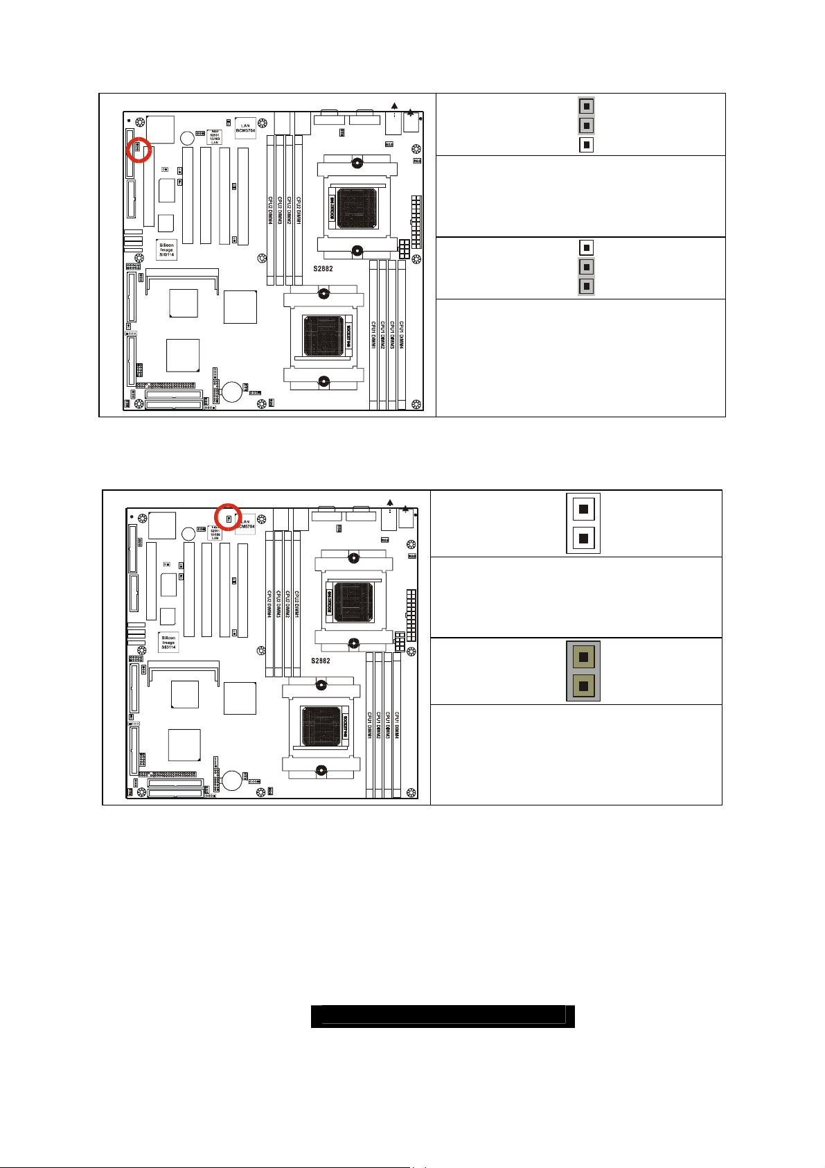
2.19 – Onboard 10/100 Ethernet Enable/Disable Jumper (J60)
)
)
LAN1/2
ATI
RAGE XL
1
FDD
J46
CH-A
1
J43
KEYLOCK
1
W83627HF
Winbond
PCI5
COM2
1
J61
INTRUDER
LAN3_LED
1
USB2
J12
J8
BIOS
SMDC
PRI-IDE
SEC-IDE
J41
ZCR J22
SCSI
7902
AMD
AMD-8111
LPT1
SATA1
SATA2
SATA3
SATA4
J23
1
SCSI-A SC SI-B
1
J19
1
J17
CMOS
1
J3
1
FAN5
1
(Optional)
J52
1
J60
Bz1
LAN3
J39
PCIX-A
PCI4 PCI3 PCI2 PCI1
1
PCIX-A
PCIX-B
J24
CH-B
AMD
AMD-8131
J11
1
1
J6
J45
BT1
J4
FAN3
1
1
LAN1_LED
1
J1
PCIX-B
J9
FAN4
1
J2
1
LAN2_LED
1
J5
CPU1_FAN
J50
J58
LAN2
LAN1
CPU1
USB1 (Bottom
LAN3 (Top)Optional
KB(Bottom)
Mouse(Top )
J55
J54
J57 (COM1)J56 (VGA)
J48
1
FAN 2
CPU2
USB1
1
CPU2_FAN
KB-MS
J47
J44
J25
CLOSED: 1 – 2
1
FAN 1
To enable onboard 10/100 Ethernet
J29
13
1
3
CLOSED: 2 – 3
To disable onboard 10/100 Ethernet
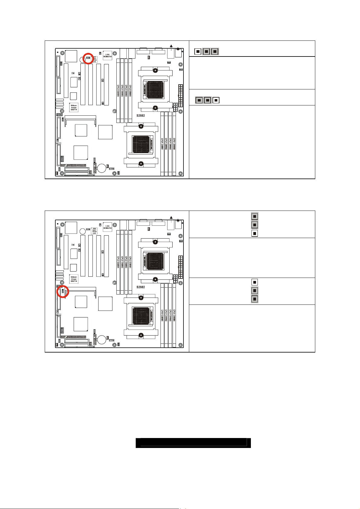
2.20 –ZCR Card Connector Select Jumper (J61) (Optional)
USB1 (Bottom
LAN3 (Top)Optional
KB(Bottom)
LAN1/2
ATI
RAGE XL
1
FDD
J46
CH-A
1
J43
KEYLOCK
1
W83627HF
Winbond
LPT1
J41
1
(Optional)
J52
1
J60
Bz1
LAN3
J39
PCIX-A
1
PCIX-A
PCIX-B
PCIX-B
J50
J58
LAN2
LAN1
J57 (COM1)J56 (VGA)
J48
1
FAN 2
J54
USB1
1
CPU2_FAN
Mouse(Top )
J55
KB-MS
J47
1
J44
CLOSED: 1 – 2
FAN 1
To enable PCI4 slot is capable of
J29
accepting the Zero Channel RAID
PCI5
BIOS
SATA1
SATA2
SATA3
SATA4
J23
1
1
J61
SCSI-A SC SI-B
1
J19
INTRUDER
1
LAN3_LED
J17
1
CMOS
1
J8
J3
1
FAN5
COM2
USB2
J12
PCI4 PCI3 PCI2 PCI1
ZCR J22
SCSI
7902
AMD
AMD-8111
SMDC
PRI-IDE
SEC-IDE
J24
CH-B
AMD
AMD-8131
J11
J9
1
1
J45
FAN4
J6
BT1
1
LAN1_LED
1
1
LAN2_LED
1
J2
J5
CPU1_FAN
J4
FAN3
1
1
J1
CPU2
CPU1
J25
card
CLOSED: 2 – 3
To enable SO-DIMM Socket (J22) is
capable of accepting the Zero
Channel RAID card
(Default)
1
3
1
3
(Default)
20
http://www.TYAN.com
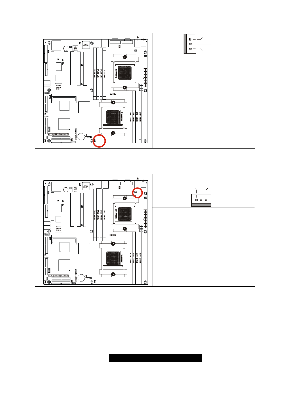
2.21 – CPU_1 Fan Connector (P1_FAN) (J5)
)
)
LAN1/2
1
J60
Bz1
LAN3
CH-A
J43
1
1
Winbond
J41
PCIX-A
PCI4 PCI3 PCI2 PCI1
ZCR J22
SCSI
7902
AMD
AMD-8111
1
J45
PRI-IDE
SEC-IDE
1
PCIX-A
J4
FAN3
J1
(Optional)
J11
1
J6
1
1
LAN1_LED
1
J52
PCIX-B
J39
1
J24
CH-B
AMD
AMD-8131
BT1
ATI
RAGE XL
1
FDD
J46
KEYLOCK
W83627HF
LPT1
PCI5
BIOS
SATA1
SATA2
SATA3
SATA4
J23
COM2
1
1
J61
SCSI-A SCSI -B
1
J19
INTRUDER
1
LAN3_LED
J17
1
USB2
J12
SMDC
CMOS
1
J8
J3
FAN5
1
J58
J50
LAN1
LAN2
PCIX-B
J9
FAN4
1
1
LAN2_LED
1
J2
J5
CPU1_FAN
CPU1
USB1 (Bottom
LAN3 (Top)Optional
KB(Bottom)
Mouse(Top)
J54
J57 (COM1)J56 (VGA)
J48
1
FAN 2
CPU2
USB1
1
CPU2_FAN
KB-MS
J47
J44
J25
2.22 – CPU_2 Fan Connector (P2_FAN) (J47)
LAN1/2
1
ATI
RAGE XL
1
FDD
J46
KEYLOCK
W83627HF
LPT1
(Optional)
J52
1
J60
Bz1
LAN3
CH-A
J43
1
1
Winbond
J41
PCIX-A
J39
1
PCIX-A
PCIX-B
J58
J50
LAN1
LAN2
PCIX-B
USB1 (Bottom
LAN3 (Top)Optional
KB(Bottom)
Mouse(Top)
J54
J57 (COM1)J56 (VGA)
J48
1
FAN 2
USB1
1
CPU2_FAN
KB-MS
J47
J44
J55
1
FAN 1
J29
Max 2.0A fans supported
without PWM fan control
with fan speed reading
J55
1
FAN 1
J29
+12V
GND
+12V
Speed
SpeedGND
PCI5
BIOS
SATA1
SATA2
SATA3
SATA4
J23
COM2
1
1
J61
SCSI-A SC SI-B
1
J19
INTRUDER
1
LAN3_LED
J17
1
CMOS
1
J8
J3
1
FAN5
USB2
J12
PCI4 PCI3 PCI2 PCI1
ZCR J22
SCSI
7902
AMD
AMD-8111
SMDC
PRI-IDE
SEC-IDE
J24
CH-B
CPU2
J25
Max 2.0A fans supported
AMD
AMD-8131
without PWM fan control
with fan speed reading
J11
J9
1
1
J45
FAN4
J6
BT1
J4
FAN3
1
LAN1_LED
1
J1
1
1
LAN2_LED
1
J2
1
J5
CPU1_FAN
CPU1
21
http://www.TYAN.com
2.23 – FAN 1 Chassis Fan Connector (J44)
)
LAN1/2
ATI
RAGE XL
1
FDD
J46
CH-A
J43
1
KEYLOCK
1
W83627HF
Winbond
PCI5
COM2
1
J61
INTRUDER
LAN3_LED
1
USB2
J12
J8
BIOS
SMDC
PRI-IDE
SEC-IDE
J41
ZCR J22
SCSI
7902
AMD
AMD-8111
LPT1
SATA1
SATA2
SATA3
SATA4
J23
1
SCSI-A SCSI-B
1
J19
1
J17
CMOS
1
J3
1
FAN5
1
(Optional)
J52
1
J60
Bz1
LAN3
J39
PCIX-A
PCI4 PCI3 PCI 2 PCI1
1
PCIX-A
PCIX-B
J24
CH-B
AMD
AMD-8131
J11
1
1
J6
J45
BT1
J4
FAN3
1
1
LAN1_L ED
1
J1
PCIX-B
J9
FAN4
1
J2
1
LAN2_LED
LAN1
1
J5
CPU1_FAN
J50
J58
LAN2
CPU1
USB1 (Bott om)
LAN3 (Top)Optional
J54
J57 (COM1)J56 (VGA)
CPU2
USB1
1
CPU2_FAN
J47
J48
1
FAN 2
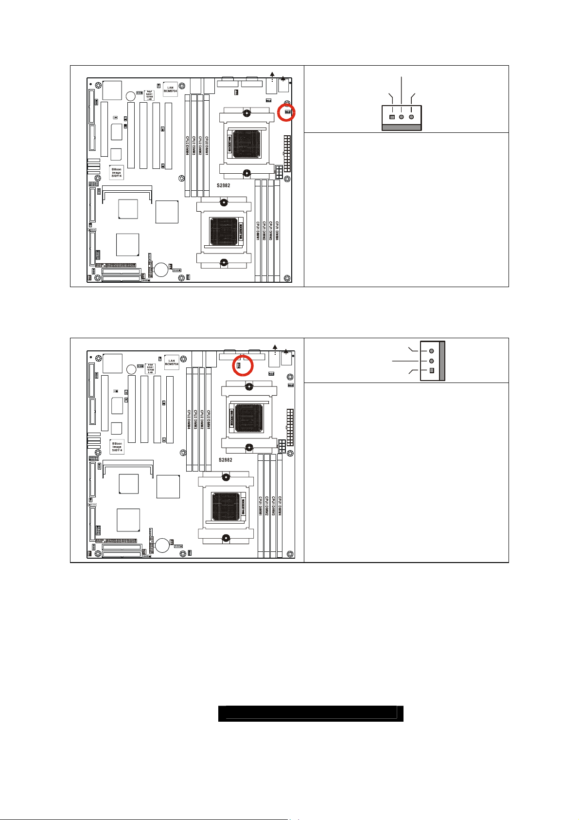
2.24 – FAN 2 Chassis Fan Connector (J48)
LAN1/2
ATI
RAGE XL
1
FDD
J46
CH-A
J43
1
KEYLOCK
1
W83627HF
Winbond
LPT1
J41
1
(Optional)
J52
1
J60
Bz1
LAN3
J39
PCIX-A
1
PCIX-A
PCIX-B
J58
J50
LAN1
LAN2
PCIX-B
USB1 (Bottom
LAN3 (Top)Optional
J54
J57 (COM1)J56 (VGA)
J48
1
FAN 2
USB1
1
CPU2_FAN
J47
J25
KB(Bottom)
Mouse(Top )
J55
KB-MS
J44
FAN 1
KB(Bottom)
Mouse(Top)
KB-MS
J44
+12V
SpeedGND
1
J29
Max 2.0A fans supported
with PWM fan control and fan speed
reading
Speed
J55
1
FAN 1
J29
+12V
GND
PCI5
BIOS
SATA1
SATA2
SATA3
SATA4
J23
COM2
1
1
J61
SCSI-A SC SI-B
1
J19
INTRUDER
1
LAN3_LED
J17
1
CMOS
1
J8
J3
1
FAN5
USB2
J12
PCI4 PCI3 PCI2 PCI1
ZCR J22
SCSI
7902
AMD
AMD-8111
SMDC
PRI-IDE
SEC-IDE
J24
CH-B
CPU2
J25
Max 2.0A fans supported
with PWM fan control and fan speed
AMD
AMD-8131
reading
J11
J9
1
1
J45
FAN4
J6
BT1
J4
FAN3
1
LAN1_LED
1
J1
1
1
LAN2_LED
1
J2
1
J5
CPU1_FAN
CPU1
22
http://www.TYAN.com
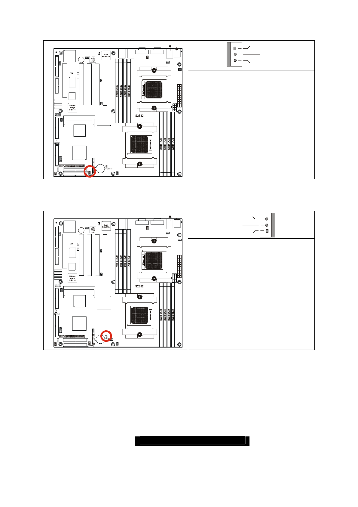
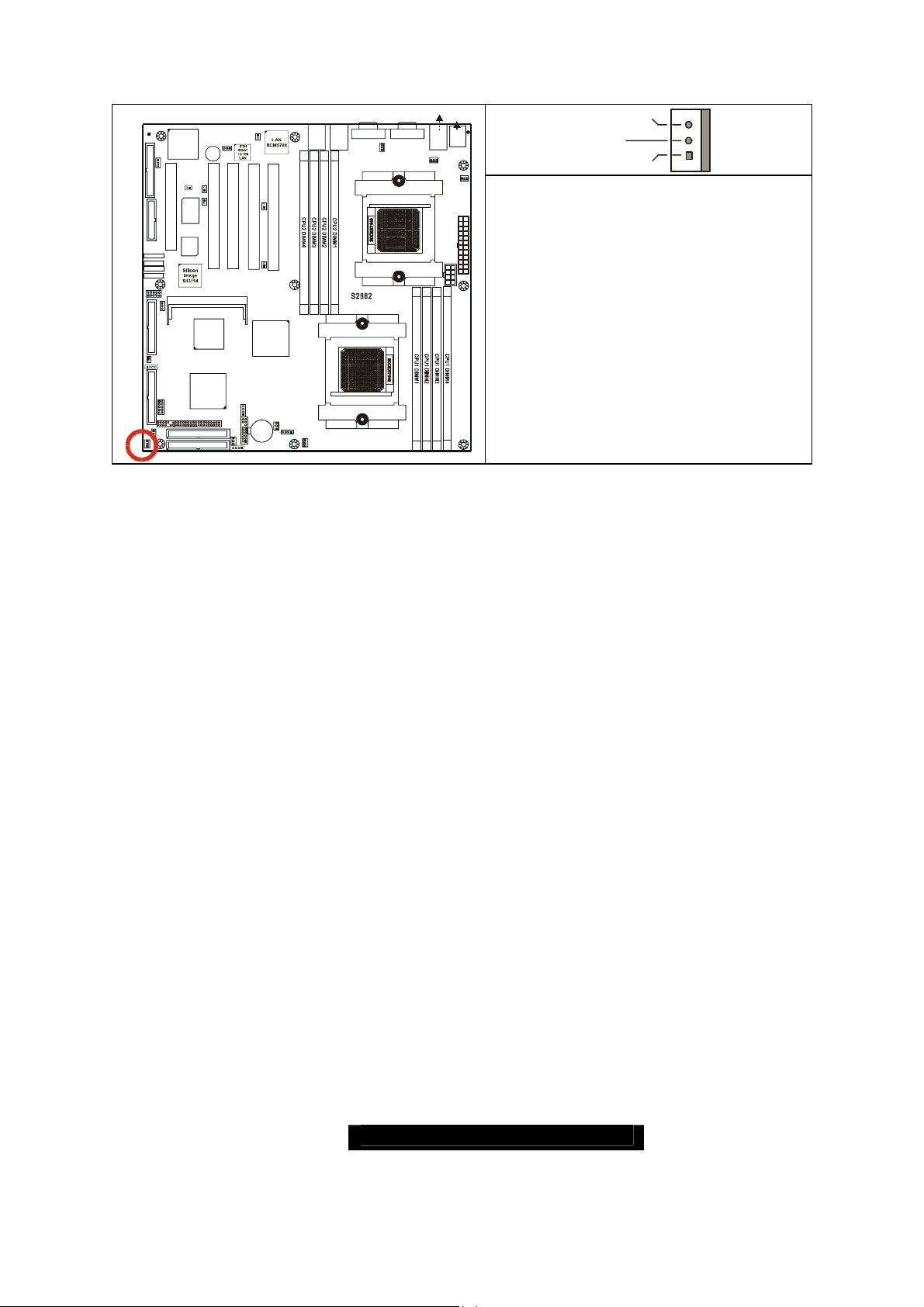
2.25 – FAN3 Chassis Fan Connector (J4)
)
)
LAN1/2
1
J60
Bz1
LAN3
CH-A
J43
1
1
Winbond
J41
PCIX-A
PCI4 PCI3 PCI2 PCI1
ZCR J22
SCSI
7902
AMD
AMD-8111
1
J45
PRI-IDE
SEC-IDE
1
PCIX-A
J4
FAN3
J1
(Optional)
J11
1
J6
1
1
LAN1_LED
1
J52
PCIX-B
J39
1
J24
CH-B
AMD
AMD-8131
BT1
ATI
RAGE XL
1
FDD
J46
KEYLOCK
W83627HF
LPT1
PCI5
BIOS
SATA1
SATA2
SATA3
SATA4
J23
COM2
1
1
J61
SCSI-A SC SI-B
1
J19
INTRUDER
1
LAN3_LED
J17
1
USB2
J12
SMDC
CMOS
1
J8
J3
1
FAN5
J58
J50
LAN1
LAN2
PCIX-B
J9
FAN4
1
1
LAN2_LED
1
J2
J5
CPU1_FAN
CPU1
J57 (COM1)J56 (VGA)
J48
1
FAN 2
CPU2
2.26 – FAN 4 Chassis Fan Connector (J9)
LAN1/2
1
ATI
RAGE XL
1
FDD
J46
KEYLOCK
W83627HF
LPT1
(Optional)
J52
1
J60
Bz1
LAN3
CH-A
J43
1
1
Winbond
J41
PCIX-A
J39
1
PCIX-A
PCIX-B
J58
J50
LAN1
LAN2
PCIX-B
J57 (COM1)J56 (VGA)
J48
1
FAN 2
USB1 (Bottom
LAN3 (Top)Optional
J54
USB1
1
CPU2_FAN
USB1 (Bottom
LAN3 (Top)Optional
J54
USB1
1
CPU2_FAN
KB(Bottom)
Mouse(Top)
J55
KB-MS
J47
1
J44
FAN 1
J29
J25
GND
+12V
Speed
Max 2.0A fans supported
with PWM fan control and fan speed
reading
KB(Bottom)
Mouse(Top)
J55
KB-MS
J47
1
J44
FAN 1
J29
Speed
+12V
GND
PCI5
BIOS
SATA1
SATA2
SATA3
SATA4
J23
COM2
1
1
J61
SCSI-A SC SI-B
1
J19
INTRUDER
1
LAN3_LED
J17
1
CMOS
1
J8
J3
1
FAN5
USB2
J12
PCI4 PCI3 PCI2 PCI1
ZCR J22
SCSI
7902
AMD
AMD-8111
SMDC
PRI-IDE
SEC-IDE
J24
CH-B
CPU2
J25
Max 3.0A fans supported
without PWM fan control
AMD
AMD-8131
with fan speed reading
J11
J9
1
1
J45
FAN4
J6
BT1
J4
FAN3
1
LAN1_LED
1
J1
1
1
LAN2_LED
1
J2
1
J5
CPU1_FAN
CPU1
23
http://www.TYAN.com
2.27 – FAN 5 Chassis Fan Connector (J3)
LAN1/2
ATI
RAGE XL
1
FDD
J46
CH-A
J43
1
KEYLOCK
1
W83627HF
Winbond
PCI5
COM2
1
J61
INTRUDER
LAN3_LED
1
USB2
J12
J8
BIOS
SMDC
PRI-IDE
SEC-IDE
J41
ZCR J22
SCSI
7902
AMD
AMD-8111
LPT1
SATA1
SATA2
SATA3
SATA4
J23
1
SCSI-A SCSI -B
1
J19
1
J17
CMOS
1
J3
1
FAN5
1
(Optiona l)
J52
1
J60
Bz1
LAN3
J39
PCIX-A
PCI4 PCI3 PCI2 PCI1
1
PCIX-A
PCIX-B
J24
CH-B
AMD
AMD-8131
J11
1
1
J6
J45
BT1
J4
FAN3
1
1
LAN1_LED
1
J1
PCIX-B
J9
FAN4
1
J2
1
LAN2_LED
LAN1
1
J5
CPU1_FAN
J50
J58
LAN2
CPU1
USB1 (Bottom)
LAN3 (Top)Optional
KB(Bottom )
Mouse(Top)
J55
J54
J57 (COM1)J56 (VGA)
J48
1
FAN 2
CPU2
USB1
1
CPU2_FAN
KB-MS
J47
1
J44
FAN 1
J29
J25
2.28 – OEM Reserved Connectors and Jumpers
The connectors and jumpers which are not listed are reserved for OEM use only.
Speed
+12V
GND
Max 3.0A fans supported
without PWM fan control
with fan speed reading
24
http://www.TYAN.com
 Loading...