

Page 1
Manual 0-2856
82 Benning Street, West Lebanon, NH 03784 USA
(603) 298-5711 • www.thermal-dynamics.com
General Information
The PCH / M-42 RPT Replacement Torches are suitable
for use with various Power Supplies and are connected
using various Adapter Kits purchased separately.
The Torches are supplied with 20 ft (6.1 m), 25 ft (7.6 m)
or 50 ft (15.2 m) Leads as follows:
Description Catalog #
PCH-42R RPT Hand Torches With Standard Handle
70° Head, 20 ft (6.1 m) Leads 7-4226
90° Head, 20 ft (6.1 m) Leads 7-4227
PCH-42ER RPT Hand T orches W ith Ergonomic Handle
70° Head, 20 ft (6.1 m) Leads 7-4220
90° Head, 20 ft (6.1 m) Leads 7-4222
70° Head, 50 ft (15.2 m) Leads 7-4221
90° Head, 50 ft (15.2 m) Leads 7-4223
PCM-42 RPT Machine Torches
180° Head, 25 ft (7.6 m) Leads 7-4224
180° Head, 50 ft (15.2 m) Leads 7-4225
These instructions are supplied to ensure the proper installation of the Replacement T orches. It is recommended
to thoroughly read the instructions first, befor e attempting the installation of the kit.
PCH / M-42 RPT
Replacement Torches
Installation Instructions
General T orch Description
The Replacement T or ches pr ovide cutting capabilities of
up to 40 amperes. In the torch, a single torch lead provides gas from a single source to be used as both the
plasma and secondary gas. The gas flow is divided inside the torch head. Single - gas operation provides a
smaller sized torch and inexpensive operation.
Torch Specifications & Design
Features
The following applies to the Replacement Torches only:
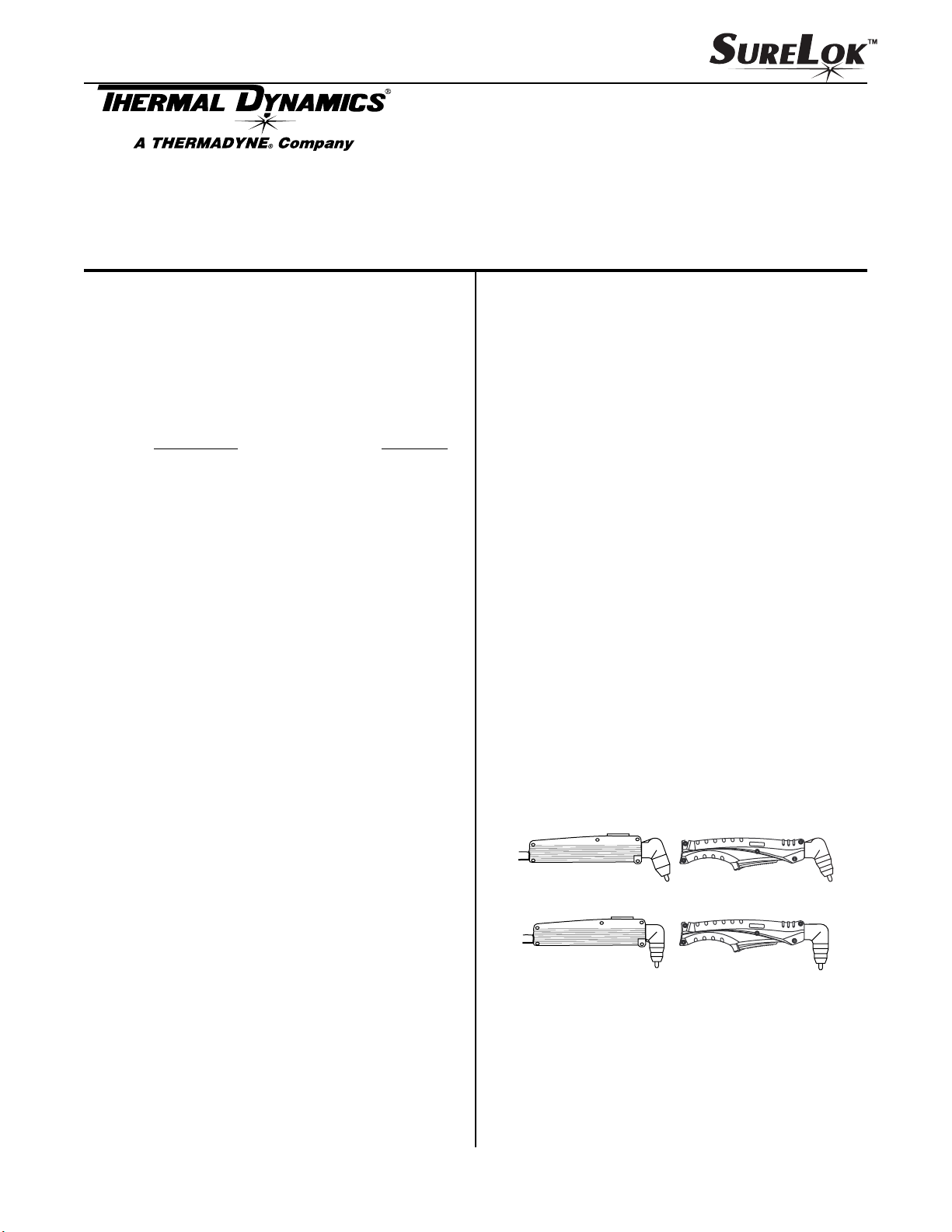
A. Torch Configurations
1. Hand T or ches
A vailable with torch head at 70° or 90° to the torch
handle. The hand torches include a torch handle
and torch switch assembly.
Torches with 20 ft (6.1 m) leads use the standard
handle with top mounted switch or the ergonomics handle with bottom mounted switch.
Torches with 50 ft (15.2 m) leads use only the ergonomics type handle and switch.
70o Hand Torches
A-02540
Supplied Parts
The following parts are supplied:
• PCH-42R, PCH-42ER or PCM-42 RPT Torch With
Leads - 1 each
• Installation Instructions - 1 each
'R' Type
Handle
© 2001 by Thermal Dynamics Corp., Printed in USA
January 23, 2004 1 Manual 0-2856
o
Hand Torches
90
'ER' Type
Handle
Page 2
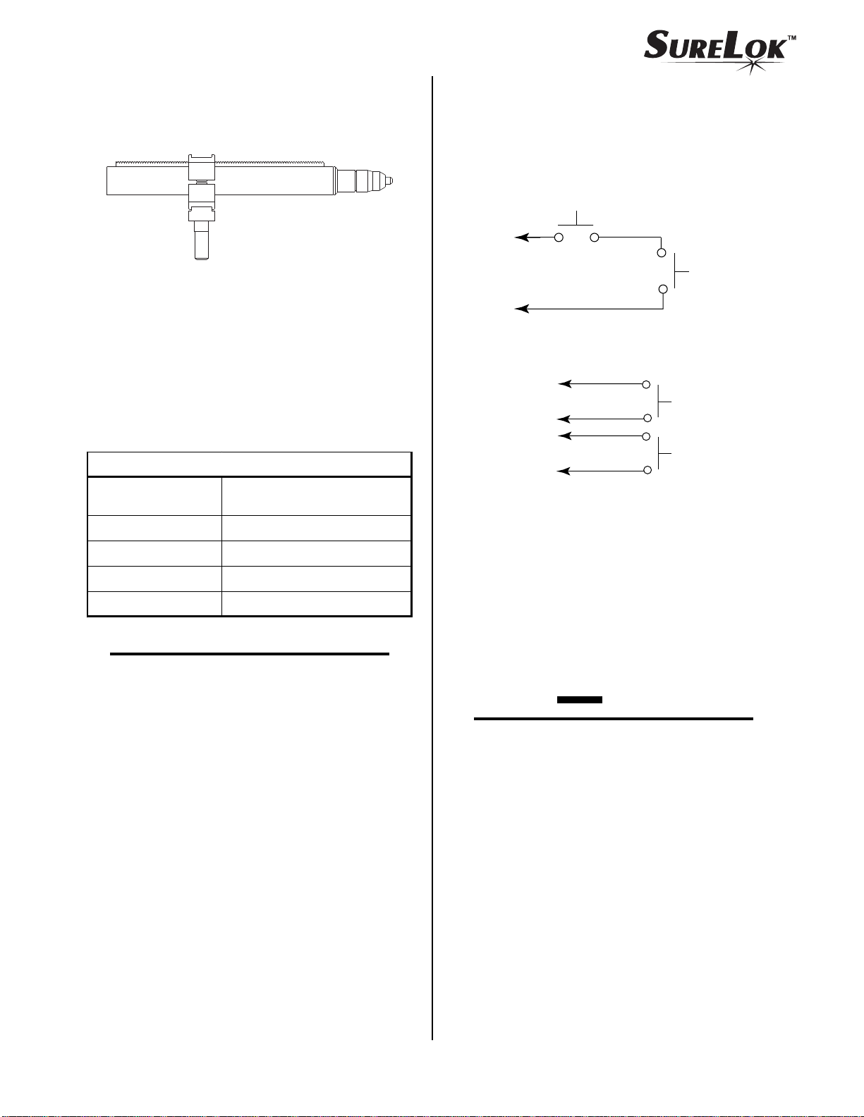
2. Machine T or ches
E. Parts - In - Place (PIP)
Available with fiberglass mounting tube & rack
and phenolic (plastic) pinch block assembly.
B. Torch Leads Lengths
• Hand Torches:
20 ft (6.1 m) or 50 ft (15.2 m)
• Machine Torches:
25 ft (7.6 m) or 50 ft (15.2 m)
C. Torch Ratings
Torch Ratings
Ambient
Temperature
Duty Cy cle
100% @ 40 Amps @ 200 scfh
104° F
(40° C)
A-02812
The torch head has built - in contacts called Parts - In
- Place (PIP). These two contacts are made through
the inside of the shield cup when it is installed. The
torch will fail to operate if these contacts are not made.
Torch Switch
PIP Pin
To Control
Cable Wiring
PIP Pin
Shield Cup
A-00458
PIP Circuit - Machine Torch
To Control
Cable Wiring
A-03540
Torch Switch
PIP Pins
Torch Trigger
Shield Cup
PIP Circuit - Hand Torch
Maxi mu m C u r r e n t
Voltage (V
peak
)
Arc Stri king Voltag e
40 Amps
500V
12 kV
NOTE
Power Supply characteristics will determine material thickness range.
D. Torch Parts
Gas Distributor , Electrode, Tip, Shield Cup
F. Gas Requirement
1. Single Plasma / Secondary Gas
Compressed Air
2. Pressure
70 psi (4.8 bar)
CAUTION
Maximum input gas pressure must not exceed 125
psi (8.6 bar)
3. Total Flow
Cutting: 200 scfh (94.4 lpm)
Gouging: 230 scfh (108.5 lpm)
scfh = standard cubic feet per hour
January 23, 2004 2 Manual 0-2856
Page 3
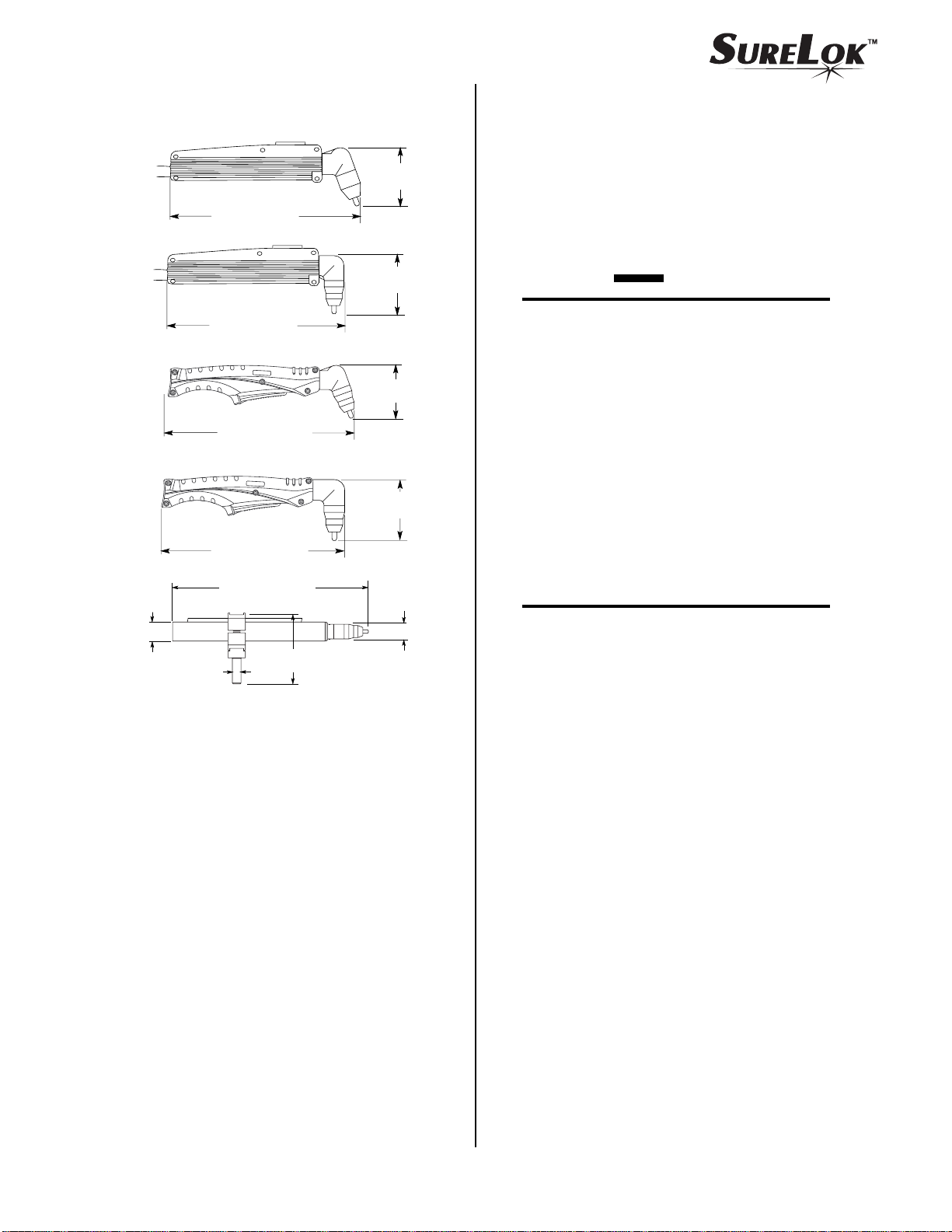
G. Dimensions
2.95 in
(75 mm)
Connecting T orch
1. Follow the instructions supplied with the appro-
priate Adapter Kit to connect the torch lead connections to the Adapter Kit parts for connection
to the Power Supply.
1.4 in
(35.6 mm)
7.98 in (203 mm)
7.31 in (186 mm)
10.5 in (266.7 mm)
9.86 in (250.4 mm)
0.6 in
(15.2 mm)
14.1 in (358 mm)
5.1 in
(130 mm)
3.13 in
(80 mm)
(76.2 mm)
3.18 in
(80.8 mm)
(27.9 mm)
A-03024
3 in
1.1 in
2. Refer to Tor ch Parts Selection and check the torch
for proper parts assembly (see CAUTION).
CAUTION
The torch parts must correspond with the type of
operation. Refer to Torch Parts Selection.
Torch Parts Selection
The type of operation to be done determines the torch
parts to be used.
Torch parts:
Shield Cup, Cutting Tip, Electrode and Gas Distributor
Type of operation:
Drag cutting, standoff cutting or gouging
NOTE
Refer to the section titled T or ch Consumables for
the various torch parts that are used depending on
the application.
I. Direct Contact Hazard
For exposed tip the recommended standoff is 1/8" 3/8" ( 3 - 9 mm).
January 23, 2004 3 Manual 0-2856
Page 4
Change the torch parts for a different operation as follows:
NOTE
The shield cup holds the tip and gas distributor in
place. Position the torch with the shield cup facing upward to prevent these parts from falling out
when the cup is removed.
1. Unscrew and remove the shield cup from the torch
head.
General T orc h Maintenance
A. Cleaning T orch
Even with only clean air , eventually the inside of the
torch becomes coated with residue. This buildup can
affect the pilot arc initiation and the overall cut quality of the torch.
WARNINGS
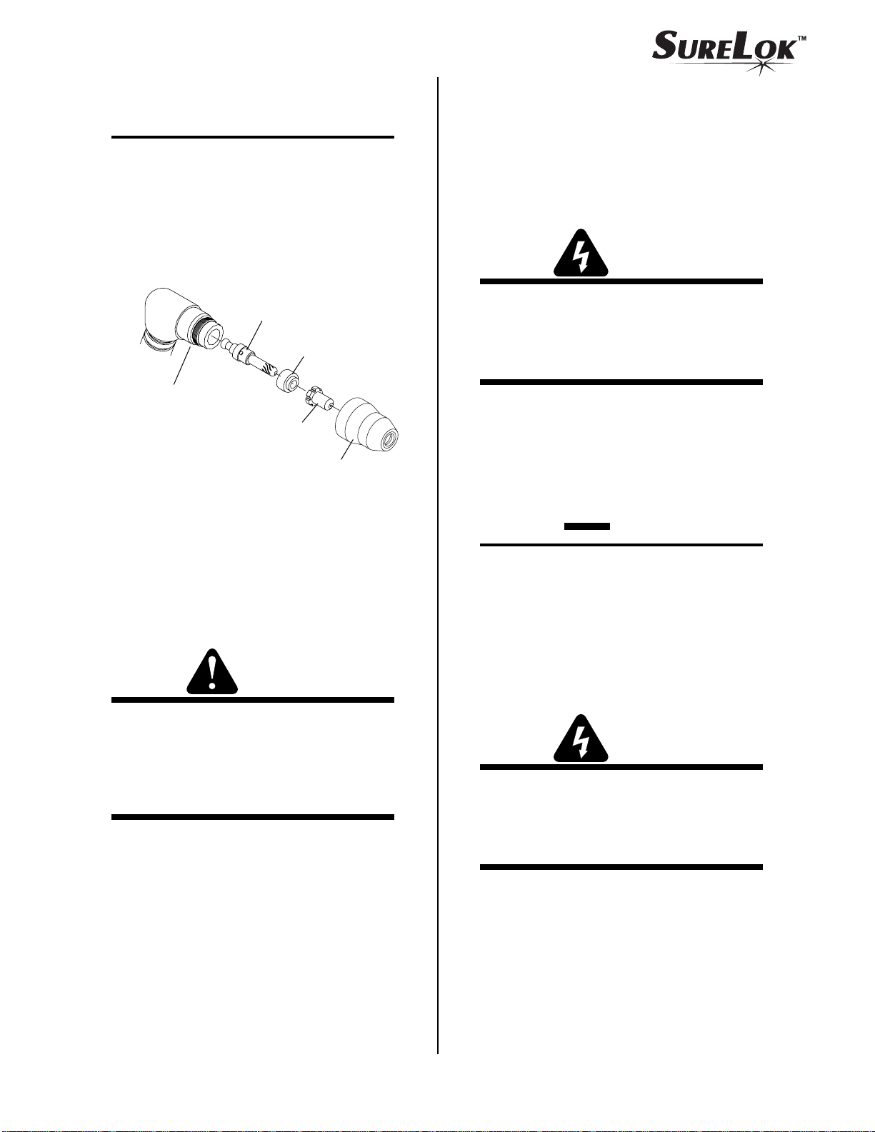
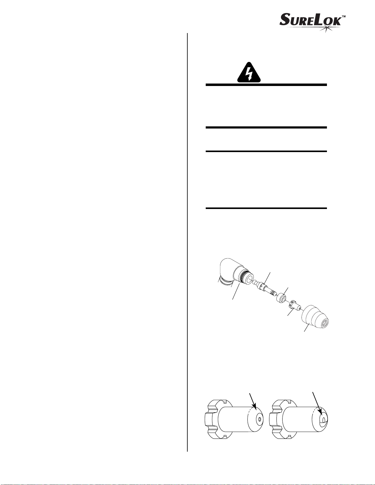
Electrode
Gas
Distributor
Torch Head Assembly
(70˚ Hand Torch Shown)
Tip
A-03025
Shield Cup
2. Tilt the torch head to r emove the tip and gas distributor .
3. Remove the SureLok Electrode by pulling it straight
out of the Torch Head.
4. Install the SureLok Electrode by pushing it straight
into the torch head until it clicks.
WARNINGS
Disconnect primary power to the system before
disassembling the torch or torch leads.
DO NOT touch any internal torch parts while the
AC indicator light of the Power Supply is ON.
The inside of the torch should be cleaned with electrical contact cleaner using a cotton swab or soft wet
rag. In severe cases, the torch can be removed from
the leads and cleaned more thoroughly by pouring
electrical contact cleaner into the torch and blowing
it through with compressed air.
CAUTION
Dry the torch thoroughly before reinstalling.
B. Checking Center Insulator
The center insulator separates the negative and positive
sections of the torch. If the center insulator does not provide adequate resistance, current which is intended for
the pilot arc may be dissipated into the torch head, resulting in torch failure.
The SureLok Electrode can only be used with the
SureLok Torch Head.
WARNINGS
The use of any consumable parts other than
those specified by the Manufacturer may cause
irreparable damage to the torch head.
5. Install the desired gas distributor and tip for the op-
eration into the torch head.
Disconnect primary power to the system before
disassembling the torch or torch leads.
DO NOT touch any internal torch parts while the
AC indicator light of the Power Supply is ON.
6. Hand tighten the shield cup until it is seated on the
torch head. If resistance is felt when installing the
cup, check the threads before proceeding.
January 23, 2004 4 Manual 0-2856
Page 5
1. Remove the shield cup, tip, gas distributor, and electrode from the torch. Disconnect the tor ch leads from
the power supply to isolate the torch from power supply circuits.
Inspection and Replacement of
Consumable T orch Parts
2. Using an ohmmeter (set to 10K or higher), check for
continuity between the positive and negative torch
fittings. Infinite resistance (no continuity) should be
found. If continuity is found there is a problem in the
Torch or Torch Leads.
Common Operating Faults
The following lists the more common cutting faults and
the possible causes:
1. Insufficient Penetration
a. Cutting speed too fast
b. Torch tilted too much
c. Metal too thick
d. Worn torch parts
e. Cutting current too low
f. Non - Genuine Thermal Dynamics Parts
2. Main Arc Extinguishes
a. Cutting speed too slow
b. Tor ch standoff too high from workpiece
WARNINGS
Disconnect primary power to the system before
disassembling the torch or torch leads.
DO NOT touch any internal torch parts while the
AC indicator light of the Power Supply is ON.
Remove the consumable torch parts as follows:
NOTE
The tip and gas distributor are held in place by the
shield cup. Position the torch with the shield cup
facing upward to prevent these parts from falling
out when the cup is removed.
1. Unscrew and remove the shield cup from the torch.
NOTE
Slag built up on the shield cup that cannot be removed may effect the performance of the system.
2. Inspect the cup for damage. Wipe it clean or replace
if damaged.
c. Cutting current too high
d. Work cable disconnected
e. Worn torch parts
f. Non - Genuine Thermal Dynamics Parts
3. Excessive Dross Formation
a. Cutting speed too slow
b. Tor ch standoff too high from workpiece
c. Worn torch parts
d. Improper cutting current
e. Non - Genuine Thermal Dynamics Parts
4. Short Torch Parts Life
a. Oil or moisture in air source
b. Exceeding system capability (material too thick)
c. Excessive pilot arc time
d. Air flow too low (incorrect pressure)
e. Improperly assembled torch
Electrode
Gas
Distributor
Torch Head Assembly
(70˚ Hand Torch Shown)
Tip
A-03025
Shield Cup
3. Remove the tip. Check for excessive wear (indicated
by an elongated or oversized orifice). Clean or replace the tip if necessary.
Good Tip
Worn Tip
f. Non - Genuine Thermal Dynamics Parts
A-00323
January 23, 2004 5 Manual 0-2856
Page 6
4. Remove the gas distributor and check for excessive
wear , plugged gas holes, or discoloration. Replace if
necessary.
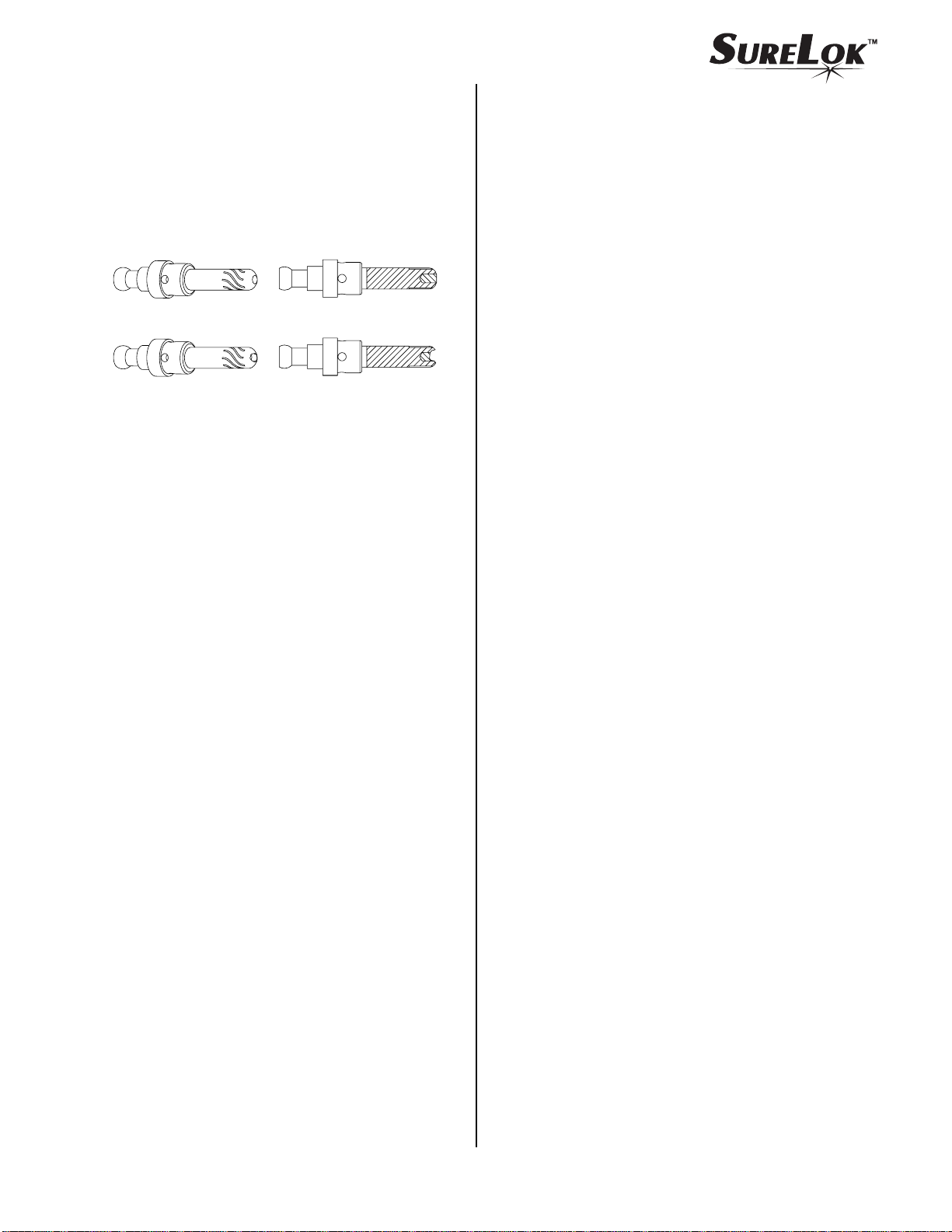
5. Remove the SureLok Electrode by pulling it straight
out of the Torch Head. Refer to the following figure
and check the face of the electrode for excessive wear .
Electrode Selection
The new SureLok PCH / M-42 RPT Torch offers a new
General Purpose Electrode. The information supplied in
this section is to describe the new electrode.
General Purpose SureLok
Electrode (Cat. No. 9-6542)
New Electrode
A-03026
Worn Electrode
6. Reinstall the SureLok Electrode by pushing it straight
into the torch head until it clicks.
7. Reinstall the gas distributor and tip into the torch head.
8. Hand tighten the shield cup until it is seated on the
torch head. If resistance is felt when installing the
cup, check the threads before proceeding.
• General Purpose - Good performance with all
systems.
• Design of electrode is similar to previous designed
electrodes used in the PCH / M-25, 26, 28, 35, and
40 Torches.
• New patented locking design offers improved
parts life, excellent piloting, improved arc transfer distance and excellent arc characteristics as
compared to older electrode designs.
• The General Purpose electrode is the standard
electrode offered with Sur eLok RPT Replacement
T orches providing good all ar ound characteristics
and performance when applied to the wide range
of older Thermal Dynamics Systems and different manufacturers’ systems.
• New innovative patented "fluted" design.
January 23, 2004 6 Manual 0-2856
Page 7

January 23, 2004 7 Manual 0-2856
Page 8

Replacement Hand Torch Parts With Standard Handle (Non - Ergonomic)
Item # Qty Description Catalog #
1 2 PIP (Parts - In - Place) Pins 9-5723
2 2 O - Ring 8-0533
3 1 Assembly, Basic Head
70° Head 9-8442
90° Head 9-8443
(For complete Torch Head Assembly refer to Complete Assembly Replacement)
4 1 Handle, Split, Two Parts (Includes Items #9 - 11) 9-6291
5 1 Lead Assembly, 20 ft (6.1 m) Length (Includes Item #6) 4-2980
6 1 Switch, Torch 9-1058
7 1 #6-32 x 3/16 Phillips Pan Head Screw See Note
8 1 #6 Internal Star Washer See Note
9 1 Button, Split Holder 8-4256
10 2 Spring 9-6292
11 6 #2-56 x 5/16" Phillips Pan Head Screw See Note
NOTE: Item can be purchased locally.
January 23, 2004 8 Manual 0-2856
Page 9

PCH-42R RPT
3
4
9
10
10
2
8
6
4
11
7
5
1
Requires Adapter Kit
For Proper Installation
Art # A-03549
January 23, 2004 9 Manual 0-2856
Page 10

Replacement Hand Torch Parts With Ergonomic Handle
Item # Qty Description Catalog #
1 1 Assembly, Basic Head
70° Head 9-8442
90° Head 9-8443
2 2 PIP (Parts - In - Place) Pins 9-5723
3 1 #6-32 x 3/16" Phillips Pan Head Screw See Note
4 1 #6 Internal Star Washer See Note
1 Ergonomic Handle, Split, with Trigger (includes items #5 - 12) 9-8076
5 1 Trigger, Lexan, Orange 9-8059
6 1 Handle 9-8060
7 1 Spring, 0.390 O.D. x 0.750 9-8061
8 1 Torch Handle Socket Head Cap Screw Kit (5 pcs 6-32 x 1/2" ) 9-8062
9 1 Assembly, Torch Switch 9-8063
10 1 Negative / Plasma Lead Insulation Sleeving 9-8056
11 3 Pin Housing (Used with item #12) 9-8111
12 3 Pin 9-8101
13 3 Socket Housing (Used with item #14) 9-8112
14 3 Socket 9-8102
15 1 Lead Assembly, including items No. 6, 8, and 9
20 ft (7.6 m) Length 4-2989
50 ft (15.2 m) Length 4-2986
NOTE: Item can be purchased locally.
January 23, 2004 10 Manual 0-2856
Page 11

PCH-42ER RPT
6
10
13 & 14
4
3
11 & 12
7
1
2
Requires Adapter Kit
For Proper Installation
5
9
6
8
15
Art # A-03547
January 23, 2004 11 Manual 0-2856
Page 12

Replacement Machine Torch Parts With Pinch Block Mounting Parts
Item # Qty Description Catalog #
1 1 Assembly, PIP (Parts - In - Place) Pins and Wire 9-5723
2 1 Assembly, Basic Head, Machine (Includes items #3 & 4) 9-8444
3 1 #6-32 x 1/16 Phillips Pan Head Screw See Note 1
4 1 #6 Internal Star Washer See Note 1
5 1 Lead Assembly
25 ft (7.6 m) Length 4-2987
50 ft (15.2 m) Length 4-2988
6 1 Positioning T ube With Rack, Fiberglass 9-7835
7 2 Body, Mounting, Pinch Block 9-4513
8 1 Pin, Mounting, Pinch Block 9-4521
9 1 Torch Holder Sleeve 7-2896
10 3 #10-32 x 5/8" Phillips Pan Head Screw See Note 1
11 2 #10-32 x 32 x 1 1/4 Lg Phillips Pan Head Screw See Note 1
12 2 #10-32 Regular Nylon Lock Nut See Note 1
13 1 T or ch Contr ol Cable
Standard - Start / Stop Control Only 9-8098
Optional - CNC / Remote Pendant Control (Adapter Kit) - See Note 2 7-3448
NOTES
1. Item can be purchased locally.
2. For use on Thermal Dynamics Products only.
January 23, 2004 12 Manual 0-2856
Page 13

PCM-42 RPT
11
7
6
10
2
4
1
3
8
7
12
9
5
Requires Adapter Kit
For Proper Installation
13
Optional
CNC/Remote Control
(Start/Stop Control Only)
Standard
Art #A-03548
January 23, 2004 13 Manual 0-2856
Page 14

Complete Assembly Replacement
NOTE
All Complete Torch and Lead Assemblies require a Torch Adapter Kit for proper installation of the Torch.
Description Catalog #
Hand Torches with Two Piece Standard Handle:
PCH-42R RPT 70° Hand Torch, 20 ft (6.1 m) Leads 7-4226
PCH-42R RPT 90° Hand Torch, 20 ft (6.1 m) Leads 7-4227
Hand Torches with Two Piece Ergonomic Handle:
PCH-42ER RPT 70° Hand Torch, 20 ft (6.1 m) Leads 7-4220
PCH-42ER RPT 90° Hand Torch, 20 ft (6.1 m) Leads 7-4222
PCH-42ER RPT 70° Hand Torch, 50 ft (15.2 m) Leads 7-4221
PCH-42ER RPT 90° Hand Torch, 50 ft (15.2 m) Leads 7-4223
Machine Torches with Unshielded Leads (Fiberglass Mounting Tube with Rack & Pinch Block Assembly):
PCM-42 RPT Machine Torch, 25 ft (7.6 m) Leads 7-4224
PCM-42 RPT Machine Torch, 50 ft (15.2 m) Leads 7-4225
January 23, 2004 14 Manual 0-2856
Page 15

Torch Consumables
WARNINGS
Use only the parts shown. Do Not attempt to use older parts that are not shown.
The use of any consumable parts other than those specified by the Manufacturer may cause irreparable
damage to the torch head.
Cutting Consumables
A-03027
SureLok
Electrode
9-6542 MaximumLife™
SureLok
Electrode
Gas
Distributor
9-6507
Gas
Distributor
MaximumLife™ Tips
Air
Drag - 20A
9-6504
Standoff - 40A
9-6500
Drag - 40A
9-6501
Gouging Consumables
MaximumLife™ Tip
Air
Shield Cups
MaximumLife™
9-6503
9-6003
9-6004
A-03439
Shield Cups
9-6542 MaximumLife™
9-6507
9-6502
9-6003
MaximumLife™
9-6503
Patented SureLok™ Technology
January 23, 2004 15 Manual 0-2856
Page 16

W ARNING - Replacing Original Machine Torch with RPT Mechanized Torch
Thermal Dynamics RPT mechanized torches have two control wires that are used for Parts - In - Place (PIP) only.
Do not connect these PIP connections directly into any start input because when the torch parts are in place, the
start signal will always be energized. If the torch parts are not in place but ar e subsequently installed with the start
signal energized, the shield cup will complete the start circuit and the unit will immediately transfer a pilot arc.
Standard Torch Control Cable For Start / Stop Only Mechanized Systems
NOTE
T o Torch
Control Device
NOTE: These wires are not present
in all configurations. If present,
leave them connected together.
Standard T orch
Control Cable
Control Connector
Plug with Connectors
types of connectors or plugs.
To Power Supply
Control Connector
Art # A-03763
Optional Torch Control Cable For CNC / Remote Pendant Systems
This option is to be used with Thermal Dynamics XR's, XL's and XL Plus Systems Only
To Torch
Control wires have various
Control Device
Torch Control
Cable
Torch Control
Connectors
Control Connector
Plug with Connectors
NOTE: These wires are
not present in all
configurations.
If present, leave them
connected together.
To Power Supply
Control Connector
Control Shield
Connector
Torch Lead
Assembly
Lead Shield
Connector
Connectors only on
Shielded Leads
Art # A-03819
NOTE
Shielded Leads are available only for Thermal Dynamics Product and are not to be installed on any other pr oducts.
January 23, 2004 16 Manual 0-2856
Page 17

Wiring Diagram
Optional Torch Control Cable For CNC / Remote Pendant Systems
Shield
Return
Power Supply
Control
OK-To-Move
Relay
A-02821
2
1
3
4
12
14
13
Torch Control
Cable Connector
Mate & Lock
Connectors
Torch Leads
Mate & Lock
Connectors
Remote Pendant/CNC
Cable Connector
Torch Head
PIP Pin
PIP Pin
3
4
12
14
13
Shield Cup
Control
OK-To-Move
Pendant Ground
NOTE
Every effort has been made to provide complete and accurate information in this manual. However, the
publisher does not assume and hereby disclaims any liability to any party for any loss or damage caused
by errors or omissions in this Manual, whether such errors result fr om negligence, accident, or any other
cause.
January 23, 2004 17 Manual 0-2856
Page 18

Statement of Warranty
LIMITED WARRANTY: Thermal Dynamics® Corporation (hereinafter “Thermal”) warrants that its products will
be free of defects in workmanship or material. Should any failure to conform to this warranty appear within the time
period applicable to the Thermal products as stated below, Thermal shall, upon notification thereof and substantiation that the product has been stored, installed, operated, and maintained in accordance with Thermal’s specifications, instructions, recommendations and recognized standard industry practice, and not subject to misuse, repair,
neglect, alteration, or accident, correct such defects by suitable repair or replacement, at Thermal’s sole option, of
any components or parts of the product determined by Thermal to be defective.
This warranty is exclusive and is in lieu of any warranty of merchantability or fitness for a particular purpose.
LIMITATION OF LIABILITY: Thermal shall not under any circumstances be liable for special or consequential
damages, such as, but not limited to, damage or loss of purchased or replacement goods, or claims of customers of
distributor (hereinafter “Purchaser”) for service interruption. The remedies of the Purchaser set forth herein are
exclusive and the liability of Thermal with respect to any contract, or anything done in connection therewith such as
the performance or breach thereof, or from the manufactur e, sale, delivery, resale, or use of any goods covered by or
furnished by Thermal whether arising out of contract, negligence, strict tort, or under any warranty, or otherwise,
shall not, except as expressly provided herein, exceed the price of the goods upon which such liability is based.
This warranty becomes invalid if replacement parts or accessories are used which may impair the safety or
performance of any Thermal Product.
This warranty becomes invalid if the product is sold by non - authorized persons.
All SureLok™ RPT Torches have a one year Parts & Labor warranty
Warranty repairs or replacement claims under this limited warranty must be submitted by an authorized Thermal
Dynamics® repair facility within thirty (30) days of the repair. No transportation costs of any kind will be paid
under this warranty. Transportation charges to send pr oducts to an authorized warranty r epair facility shall be the
responsibility of the customer. All returned goods shall be at the customer’s risk and expense.
Thermal Dynamics Corporation
82 Benning Street
West Lebanon, NH 03784 USA
Telephone: 603-298-5711
www.thermal-dynamics.com
January 23, 2004 18 Manual 0-2856
 Loading...