

Page 1

HMC-410
AUTOMATIC &
SEMI-AUTOMATIC
CONTROL PANEL
Instruction Manual
V
ersion No: AA.02 Issue Date: July 27, 2005 Manual #: 430429-445
Operating Features:
120
VAC
50
60
888
Hz
IPM
Art # A-04355
Page 2

WE APPRECIA TE YOUR BUSINESS!
Congratulations on your new Thermal Arc product. We are proud
to have you as our customer and will strive to provide you with
the best service and reliability in the industry. This product is backed
by our extensive warranty and world-wide service network. To
locate your nearest distributor or service agency call
1-800-752-7621, or visit us on the web at www.Thermalarc.com.
This Operating Manual has been designed to instruct you on the
correct use and operation of your Thermal Arc product. Your
satisfaction with this product and its safe operation is our ultimate
concern. Therefore please take the time to read the entire manual,
especially the Safety Precautions. They will help you to avoid
potential hazards that may exist when working with this product.
YOU ARE IN GOOD COMPANY!
The Brand of Choice for Contractors and Fabricators Worldwide.
Thermal Arc is a Global Brand of Arc Welding Products for
Thermadyne Industries Inc. We manufacture and supply to major
welding industry sectors worldwide including; Manufacturing,
Construction, Mining, Automotive, Aerospace, Engineering, Rural
and DIY/Hobbyist.
We distinguish ourselves from our competition through marketleading, dependable products that have stood the test of time. We
pride ourselves on technical innovation, competitive prices,
excellent delivery, superior customer service and technical support,
together with excellence in sales and marketing expertise.
Above all, we are committed to develop technologically advanced
products to achieve a safer working environment within the welding
industry.
Page 3

WARNINGS
Read and understand this entire Manual and your employer’s safety practices before installing,
operating, or servicing the equipment.
While the information contained in this Manual represents the Manufacturer's best judgement,
the Manufacturer assumes no liability for its use.
HMC-410 Automatic/Semi-Automatic Control Panel
Instruction Manual Number 430429-445 for:
Spec Number 100050-1
Spec Number 100050-2
Published by:
Thermadyne Industries
82 Benning Street
West Lebanon, New Hampshire, USA 03784
(603) 298-5711
www.thermalarc.com
Copyright 2005 by
Thermal Dynamics Corporation
All rights reserved.
Reproduction of this work, in whole or in part, without written permission of the publisher is prohibited.
The publisher does not assume and hereby disclaims any liability to any party for any
loss or damage caused by any error or omission in this Manual, whether such error
results from negligence, accident, or any other cause.
Publication Date: Juky 27, 2005
Record the following information for Warranty purposes:
Where Purchased: ___________________________________
Purchase Date: ___________________________________
Equipment Serial #: ___________________________________
i
Page 4

TABLE OF CONTENTS
SECTION 1:
SAFETY INSTRUCTIONS AND WARNINGS ....................................................... 1-1
1.01 Arc Welding Hazards ...................................................................................... 1-1
1.02 PRINCIPAL SAFETY STANDARDS .................................................................. 1-5
1.03 PRECAUTIONS DE SECURITE EN SOUDAGE A L’ARC .................................... 1-6
1.04 Dangers relatifs au soudage à l’arc ................................................................. 1-6
1.05 PRINCIPALES NORMES DE SECURITE ........................................................ 1-10
1.06 DECLARATION OF CONFORMITY ................................................................. 1-11
1.07 LIMITED WARRANTY ................................................................................... 1-12
SECTION 2:
INTRODUCTION ...................................................................................... 2-1
2.01 How To Use This Manual ................................................................................ 2-1
2.02 Equipment Identification................................................................................. 2-1
2.03 Receipt Of Equipment ..................................................................................... 2-1
2.04 Symbol Chart ................................................................................................. 2-2
2.05 General Information ....................................................................................... 2-3
2.06 Product Specifications ................................................................................... 2-3
2.07 Front Panel Controls ....................................................................................... 2-7
2.08 Rear Panel Connections ............................................................................... 2-11
2.09 Power Source Interface Description ............................................................. 2-13
2.10 Hardware Description ................................................................................... 2-14
SECTION 3:
INSTALLATION ....................................................................................... 3-1
3.01 Location ......................................................................................................... 3-1
3.02 Assembly ........................................................................................................ 3-1
3.03 Electrical Connections .................................................................................... 3-1
3.04 Load Suppression .......................................................................................... 3-1
3.05 Grounding ...................................................................................................... 3-2
SECTION 4:
OPERATION........................................................................................... 4-1
4.01 System Configuration ..................................................................................... 4-1
4.02 Softswitch Description (Table 4-1) ................................................................. 4-2
4.03 System Setup ............................................................................................... 4-10
4.04 HMC-410 Setup Checklist ............................................................................ 4-12
4.05 Programming ............................................................................................... 4-13
4.06 Setup ............................................................................................................ 4-16
4.07 Operation ...................................................................................................... 4-17
Page 5

TABLE OF CONTENTS (continued)TABLE OF CONTENTS
SECTION 5:
SERVICE .............................................................................................. 5-1
5.01 Maintenance ................................................................................................... 5-1
5.02 Controller Maintenance .................................................................................. 5-1
5.03 Troubleshooting ............................................................................................. 5-1
5.04 Troubleshooting Guide ................................................................................... 5-2
5.05 Diagnostics..................................................................................................... 5-6
5.06 Built In Test (BIT) Definition ........................................................................... 5-7
5.06 Built In Test (BIT) Definition (continued as Table 5-1b).................................. 5-8
5.06 Built In Test (BIT) Definition (continued as Table 5-1c) .................................. 5-9
SECTION 6:
ACCESSORIES AND OPTION DESCRIPTIONS.................................................... 6-1
6.01 Remote Pendant Description .......................................................................... 6-1
6.02 Feedhead ........................................................................................................ 6-1
6.03 Feed Roll Kits ................................................................................................. 6-1
6.04 Control Cables: ............................................................................................... 6-2
6.05 171238-17 Software Kits ................................................................................ 6-2
6.06 171238-19 Software Kits ................................................................................ 6-3
6.07 171238 Software Kits ..................................................................................... 6-3
6.08 870236 Robotic Interface Kits ........................................................................ 6-4
6.09 870236-002 Fanuc Robotic Interface Kit ........................................................ 6-5
6.10 870236-003 Comau Robotic Interface Kit ...................................................... 6-6
6.11 Other Available Options .................................................................................. 6-7
SECTION 7:
GLOSSARY ........................................................................................... 7-1
SECTION 8:
PARTS LIST .......................................................................................... 6-1
8.01 Equipment Identification................................................................................. 6-1
8.02 How To Use This Parts List ............................................................................ 6-1
8.03 Parts List for the Control Box Assembly (1 of 2) ............................................ 6-2
8.03 Parts List for the Control Box Assembly (2 of 2) ............................................ 6-4
8.04 Parts List for the Remote Pendant ................................................................. 6-6
APPENDIX 1: GENERAL INFORMATION ................................................................. A-1
APPENDIX 2: SCHEMATIC DIAGRAM 1 OF 4 ........................................................... A-2
APPENDIX 3: SCHEMATIC DIAGRAM 2 OF 4 ........................................................... A-4
APPENDIX 4: SCHEMATIC DIAGRAM 3 OF 4 ........................................................... A-6
APPENDIX 5: SCHEMATIC DIAGRAM 4 OF 4 ........................................................... A-8
Page 6

TABLE OF CONTENTS
APPENDIX 6: SYSTEM OUTLINE 1 OF 2 ............................................................... A-10
APPENDIX 7: SYSTEM OUTLINE 2 OF 2 ............................................................... A-11
Page 7

HMC-410
SECTION 1:
SAFETY INSTRUCTIONS AND WARNINGS
WARNING
PROTECT YOURSELF AND OTHERS FROM POSSIBLE SERIOUS INJURY OR DEATH. KEEP CHILDREN AWAY.
PACEMAKER WEARERS KEEP AWAY UNTIL CONSULTING YOUR DOCTOR. DO NOT LOSE THESE INSTRUCTIONS.
READ OPERATING/INSTRUCTION MANUAL BEFORE INSTALLING, OPERATING OR SERVICING THIS EQUIPMENT.
Welding products and welding processes can cause serious injury or death, or damage to other equipment or property,
if the operator does not strictly observe all safety rules and take precautionary actions.
Safe practices have developed from past experience in the use of welding and cutting. These practices must be
learned through study and training before using this equipment. Some of these practices apply to equipment
connected to power lines; other practices apply to engine driven equipment. Anyone not having extensive
training in welding and cutting practices should not attempt to weld.
Safe practices are outlined in the American National Standard Z49.1 entitled:
This publication and other guides to what you should learn before operating this equipment are listed at the end of
these safety precautions. HAVE ALL INSTALLATION, OPERATION, MAINTENANCE, AND REPAIR WORK PERFORMED
ONLY BY QUALIFIED PEOPLE.
SAFETY IN WELDING AND CUTTING.
1.01 Arc Welding Hazards
WARNING
ELECTRIC SHOCK can kill.
Touching live electrical parts can cause fatal
shocks or severe burns. The electrode and
work circuit is electrically live whenever the
output is on. The input power circuit and
machine internal circuits are also live when
power is on. In semiautomatic or automatic
wire welding, the wire, wire reel, drive roll
housing, and all metal parts touching the
welding wire are electrically live. Incorrectly
installed or improperly grounded equipment
is a hazard.
3. Insulate yourself from work and ground using dry
insulating mats or covers.
4. Disconnect input power or stop engine before
installing or servicing this equipment. Lock input
power disconnect switch open, or remove line fuses
so power cannot be turned on accidentally.
5. Properly install and ground this equipment according
to its Owner’s Manual and national, state, and local
codes.
6. Turn off all equipment when not in use. Disconnect
power to equipment if it will be left unattended or out
of service.
7. Use fully insulated electrode holders. Never dip holder
in water to cool it or lay it down on the ground or the
work surface. Do not touch holders connected to two
welding machines at the same time or touch other
people with the holder or electrode.
8. Do not use worn, damaged, undersized, or poorly
spliced cables.
1. Do not touch live electrical parts.
2. Wear dry, hole-free insulating gloves and body
protection.
July 27, 2005
9. Do not wrap cables around your body.
10.Ground the workpiece to a good electrical (earth)
ground.
1-1
Page 8
HMC-410
11.Do not touch electrode while in contact with the work
(ground) circuit.
12. Use only well-maintained equipment. Repair or replace
damaged parts at once.
13.In confined spaces or damp locations, do not use a
welder with AC output unless it is equipped with a
voltage reducer. Use equipment with DC output.
14.Wear a safety harness to prevent falling if working
above floor level.
15.Keep all panels and covers securely in place.
WARNING
ARC RAYS can burn eyes and skin; NOISE can
damage hearing.
Arc rays from the welding process produce
intense heat and strong ultraviolet rays that
can burn eyes and skin. Noise from some
processes can damage hearing.
4. Wear protective clothing made from durable, flameresistant material (wool and leather) and foot
protection.
5. Use approved ear plugs or ear muffs if noise level is
high.
WARNING
FUMES AND GASES can be hazardous to your
health.
Welding produces fumes and gases. Breathing
these fumes and gases can be hazardous to
your health.
1. Keep your head out of the fumes. Do not breath the
fumes.
2. If inside, ventilate the area and/or use exhaust at the
arc to remove welding fumes and gases.
3. If ventilation is poor, use an approved air-supplied
respirator.
1. Wear a welding helmet fitted with a proper shade of
filter (see ANSI Z49.1 listed in Safety Standards) to
protect your face and eyes when welding or watching.
2. Wear approved safety glasses. Side shields
recommended.
3. Use protective screens or barriers to protect others
from flash and glare; warn others not to watch the
arc.
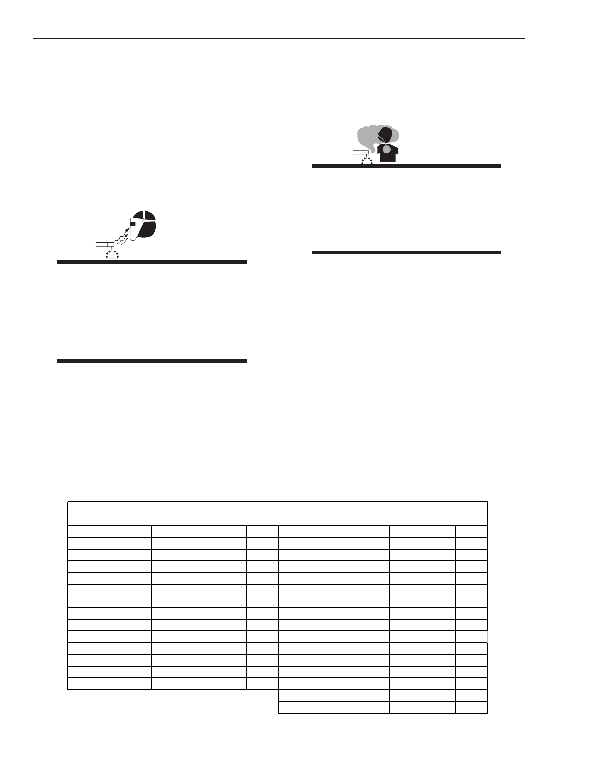
Eye protection filter shade selector for welding or cutting
(goggles or helmet), from AWS A6.2-73.
Welding or cutting Electrode Size Filter Welding or cutting Electrode Size Filter
Torch soldering 2
Torch brazing 3 or 4 Non-ferrous base metal All 11
Oxygen Cutting
Light Under 1 in., 25 mm 3 or 4 Gas tungsten arc welding All 12
Medium 1 to 6 in., 25-150 mm 4 or 5 (TIG) All 12
Heavy Over 6 in., 150 mm 5 or 6 Atomic hydrogen welding All 12
Ga s w eld ing
Light Under 1/8 in., 3 mm 4 or 5 Plasma arc welding
Medium 1/8 to 1/2 in., 3-12 mm 5 or 6
Heavy Over 1/2 in., 12 mm 6 or 8 Light 12
Shielded me tal-arc
Under 5/32 in., 4 mm 10 Heavy 14
5/32 to 1/4 in., 12
Over 1/4 in., 6.4 mm 14 Light Under 300 Amp 9
4. Read the Material Safety Data Sheets (MSDSs) and
the manufacturer’s instruction for metals,
consumables, coatings, and cleaners.
5. Work in a confined space only if it is well ventilated,
or while wearing an air-supplied respirator. Shielding
gases used for welding can displace air causing injury
or death. Be sure the breathing air is safe.
Gas metal-arc
Ferrous bas e metal All 12
Carbon arc welding All 12
Carbon arc air gouging
Plasma arc cutting
Medium 300 to 400 Amp 12
Heavy Over 400 Amp 14
1-2
July 27, 2005
Page 9
6. Do not weld in locations near degreasing, cleaning, or
spraying operations. The heat and rays of the arc can
react with vapors to form highly toxic and irritating
gases.
7. Do not weld on coated metals, such as galvanized,
lead, or cadmium plated steel, unless the coating is
removed from the weld area, the area is well ventilated,
and if necessary, while wearing an air-supplied
respirator. The coatings and any metals containing
these elements can give off toxic fumes if welded.
WARNING
WELDING can cause fire or explosion.
HMC-410
WARNING
FLYING SPARKS AND HOT METAL can cause
injury.
Chipping and grinding cause flying metal. As
welds cool, they can throw off slag.
1. Wear approved face shield or safety goggles. Side
shields recommended.
2. Wear proper body protection to protect skin.
WARNING
Sparks and spatter fly off from the welding
arc. The flying sparks and hot metal, weld
spatter, hot workpiece, and hot equipment can
cause fires and burns. Accidental contact of
electrode or welding wire to metal objects can
cause sparks, overheating, or fire.
1. Protect yourself and others from flying sparks and
hot metal.
2. Do not weld where flying sparks can strike flammable
material.
3. Remove all flammables within 35 ft (10.7 m) of the
welding arc. If this is not possible, tightly cover them
with approved covers.
4. Be alert that welding sparks and hot materials from
welding can easily go through small cracks and
openings to adjacent areas.
5. Watch for fire, and keep a fire extinguisher nearby.
6. Be aware that welding on a ceiling, floor, bulkhead, or
partition can cause fire on the hidden side.
7. Do not weld on closed containers such as tanks or
drums.
8. Connect work cable to the work as close to the welding
area as practical to prevent welding current from
traveling long, possibly unknown paths and causing
electric shock and fire hazards.
9. Do not use welder to thaw frozen pipes.
CYLINDERS can explode if damaged.
Shielding gas cylinders contain gas under high
pressure. If damaged, a cylinder can explode.
Since gas cylinders are normally part of the
welding process, be sure to treat them
carefully.
1. Protect compressed gas cylinders from excessive heat,
mechanical shocks, and arcs.
2. Install and secure cylinders in an upright position by
chaining them to a stationary support or equipment
cylinder rack to prevent falling or tipping.
3. Keep cylinders away from any welding or other
electrical circuits.
4. Never allow a welding electrode to touch any cylinder.
5. Use only correct shielding gas cylinders, regulators,
hoses, and fittings designed for the specific
application; maintain them and associated parts in
good condition.
6. Turn face away from valve outlet when opening
cylinder valve.
7. Keep protective cap in place over valve except when
cylinder is in use or connected for use.
8. Read and follow instructions on compressed gas
cylinders, associated equipment, and CGA publication
P-1 listed in Safety Standards.
10.Remove stick electrode from holder or cut off welding
wire at contact tip when not in use.
July 27, 2005
1-3
Page 10
HMC-410
WARNING
Engines can be dangerous.
WARNING
ENGINE EXHAUST GASES can kill.
4. To prevent accidental starting during servicing,
disconnect negative (-) battery cable from battery.
5. Keep hands, hair, loose clothing, and tools away
from moving parts.
6. Reinstall panels or guards and close doors when
servicing is finished and before starting engine.
WARNING
Engines produce harmful exhaust gases.
1. Use equipment outside in open, well-ventilated areas.
2. If used in a closed area, vent engine exhaust outside
and away from any building air intakes.
WARNING
ENGINE FUEL can cause fire or explosion.
Engine fuel is highly flammable.
1. Stop engine before checking or adding fuel.
2. Do not add fuel while smoking or if unit is near any
sparks or open flames.
3. Allow engine to cool before fueling. If possible, check
and add fuel to cold engine before beginning job.
4. Do not overfill tank — allow room for fuel to expand.
5. Do not spill fuel. If fuel is spilled, clean up before
starting engine.
SPARKS can cause BATTERY GASES TO
EXPLODE; BATTERY ACID can burn eyes and
skin.
Batteries contain acid and generate explosive gases.
1. Always wear a face shield when working on a battery.
2. Stop engine before disconnecting or connecting
battery cables.
3. Do not allow tools to cause sparks when working on
a battery.
4. Do not use welder to charge batteries or jump start
vehicles.
5. Observe correct polarity (+ and –) on batteries.
WARNING
STEAM AND PRESSURIZED HOT COOLANT
can burn face, eyes, and skin.
WARNING
MOVING PARTS can cause injury.
Moving parts, such as fans, rotors, and belts can cut
fingers and hands and catch loose clothing.
1. Keep all doors, panels, covers, and guards closed
and securely in place.
2. Stop engine before installing or connecting unit.
3. Have only qualified people remove guards or
covers for maintenance and troubleshooting as
necessary.
1-4
The coolant in the radiator can be very hot
and under pressure.
1. Do not remove radiator cap when engine is hot. Allow
engine to cool.
2. Wear gloves and put a rag over cap area when
removing cap.
3. Allow pressure to escape before completely removing
cap.
July 27, 2005
Page 11

HMC-410
WARNING
This product, when used for welding or
cutting, produces fumes or gases which
contain chemicals know to the State of
California to cause birth defects and, in some
cases, cancer. (California Health & Safety code
Sec. 25249.5 et seq.)
NOTE
Considerations About Welding And The Effects
of Low Frequency Electric and Magnetic Fields
The following is a quotation from the General Conclusions
Section of the U.S. Congress, Office of Technology
Assessment,
Frequency Electric & Magnetic Fields - Background Paper,
OTA-BP-E-63 (Washington, DC: U.S. Government Printing
Office, May 1989): “...there is now a very large volume of
scientific findings based on experiments at the cellular
level and from studies with animals and people which
clearly establish that low frequency magnetic fields and
interact with, and produce changes in, biological systems.
While most of this work is of very high quality, the results
are complex. Current scientific understanding does not
yet allow us to interpret the evidence in a single coherent
framework. Even more frustrating, it does not yet allow
us to draw definite conclusions about questions of
possible risk or to offer clear science-based advice on
strategies to minimize or avoid potential risks.”
To reduce magnetic fields in the workplace, use the
following procedures.
1. Keep cables close together by twisting or taping
them.
Biological Effects of Power
1.02 PRINCIPAL SAFETY STANDARDS
Safety in Welding and Cutting, ANSI Standard Z49.1, from
American Welding Society, 550 N.W. LeJeune Rd., Miami,
FL 33126.
Safety and Health Standards, OSHA 29 CFR 1910, from
Superintendent of Documents, U.S. Government Printing
Office, Washington, D.C. 20402.
Recommended Safe Practices for the Preparation for
Welding and Cutting of Containers That Have Held
Hazardous Substances, American Welding Society
Standard AWS F4.1, from American Welding Society, 550
N.W. LeJeune Rd., Miami, FL 33126.
National Electrical Code, NFPA Standard 70, from National
Fire Protection Association, Batterymarch Park, Quincy,
MA 02269.
Safe Handling of Compressed Gases in Cylinders, CGA
Pamphlet P-1, from Compressed Gas Association, 1235
Jefferson Davis Highway, Suite 501, Arlington, VA 22202.
Code for Safety in Welding and Cutting, CSA Standard
W117.2, from Canadian Standards Association, Standards
Sales, 178 Rexdale Boulevard, Rexdale, Ontario, Canada
M9W 1R3.
Safe Practices for Occupation and Educational Eye and
Face Protection, ANSI Standard Z87.1, from American
National Standards Institute, 1430 Broadway, New York,
NY 10018.
Cutting and Welding Processes, NFPA Standard 51B, from
National Fire Protection Association, Batterymarch Park,
Quincy, MA 02269.
2. Arrange cables to one side and away from the
operator.
3. Do not coil or drape cable around the body.
4. Keep welding power source and cables as far away
from body as practical.
ABOUT PACEMAKERS:
The above procedures are among those also
normally recommended for pacemaker
wearers. Consult your doctor for complete
information.
July 27, 2005
1-5
Page 12

HMC-410
1.03 PRECAUTIONS DE SECURITE EN SOUDAGE A L’ARC
MISE EN GARDE
LE SOUDAGE A L’ARC EST DANGEREUX
PROTEGEZ-VOUS, AINSI QUE LES AUTRES, CONTRE LES BLESSURES GRAVES POSSIBLES OU LA MORT. NE LAISSEZ
PAS LES ENFANTS S’APPROCHER, NI LES PORTEURS DE STIMULATEUR CARDIAQUE (A MOINS QU’ILS N’AIENT
CONSULTE UN MEDECIN). CONSERVEZ CES INSTRUCTIONS. LISEZ LE MANUEL D’OPERATION OU LES INSTRUCTIONS AVANT D’INSTALLER, UTILISER OU ENTRETENIR CET EQUIPEMENT.
Les produits et procédés de soudage peuvent sauser des blessures graves ou la mort, de même que des dommages
au reste du matériel et à la propriété, si l’utilisateur n’adhère pas strictement à toutes les règles de sécurité et ne prend
pas les précautions nécessaires.
En soudage et coupage, des pratiques sécuritaires se sont développées suite à l’expérience passée. Ces pratiques
doivent être apprises par étude ou entraînement avant d’utiliser l’equipement. Toute personne n’ayant pas suivi un
entraînement intensif en soudage et coupage ne devrait pas tenter de souder. Certaines pratiques concernent les
équipements raccordés aux lignes d’alimentation alors que d’autres s’adressent aux groupes électrogènes.
La norme Z49.1 de l’American National Standard, intitulée “SAFETY IN WELDING AND CUTTING” présente les pratiques sécuritaires à suivre. Ce document ainsi que d’autres guides que vous devriez connaître avant d’utiliser cet
équipement sont présentés à la fin de ces instructions de sécurité.
SEULES DES PERSONNES QUALIFIEES DOIVENT FAIRE
DES TRAVAUX D’INSTALLATION, DE REPARATION,
D’ENTRETIEN ET D’ESSAI.
1. Ne touchez pas à des pièces sous tension.
2. Portez des gants et des vêtements isolants, secs et
non troués.
1.04 Dangers relatifs au soudage à l’arc
AVERTISSEMENT
L’ELECTROCUTION PEUT ETRE MORTELLE.
Une décharge électrique peut tuer ou brûler
gravement. L’électrode et le circuit de soudage
sont sous tension dès la mise en circuit. Le
circuit d’alimentation et les circuits internes
de l’équipement sont aussi sous tension dès
la mise en marche. En soudage automatique
ou semi-automatique avec fil, ce dernier, le
rouleau ou la bobine de fil, le logement des
galets d’entrainement et toutes les pièces
métalliques en contact avec le fil de soudage
sont sous tension. Un équipement
inadéquatement installé ou inadéquatement
mis à la terre est dangereux.
1-6
3 Isolez-vous de la pièce à souder et de la mise à la
terre au moyen de tapis isolants ou autres.
4. Déconnectez la prise d’alimentation de l’équipement
ou arrêtez le moteur avant de l’installer ou d’en faire
l’entretien. Bloquez le commutateur en circuit ouvert
ou enlevez les fusibles de l’alimentation afin d’éviter
une mise en marche accidentelle.
5. Veuillez à installer cet équipement et à le mettre à la
terre selon le manuel d’utilisation et les codes
nationaux, provinciaux et locaux applicables.
6. Arrêtez tout équipement après usage. Coupez
l’alimentation de l’équipement s’il est hors d’usage
ou inutilisé.
7. N’utilisez que des porte-électrodes bien isolés. Ne
jamais plonger les porte-électrodes dans l’eau pour
les refroidir. Ne jamais les laisser traîner par terre ou
sur les pièces à souder. Ne touchez pas aux porteélectrodes raccordés à deux sources de courant en
même temps. Ne jamais toucher quelqu’un d’autre
avec l’électrode ou le porte-électrode.
8. N’utilisez pas de câbles électriques usés,
endommagés, mal épissés ou de section trop petite.
9. N’enroulez pas de câbles électriques autour de votre
corps.
July 27, 2005
Page 13
HMC-410
10.N’utilisez qu’une bonne prise de masse pour la mise à
la terre de la pièce à souder.
11.Ne touchez pas à l’électrode lorsqu’en contact avec le
circuit de soudage (terre).
12.N’utilisez que des équipements en bon état. Réparez
ou remplacez aussitôt les pièces endommagées.
13.Dans des espaces confinés ou mouillés, n’utilisez pas
de source de courant alternatif, à moins qu’il soit muni
d’un réducteur de tension. Utilisez plutôt une source
de courant continu.
14. Portez un harnais de sécurité si vous travaillez en hauteur.
15.Fermez solidement tous les panneaux et les capots.
AVERTISSEMENT
LE RAYONNEMENT DE L’ARC PEUT BRÛLER
LES YEUX ET LA PEAU; LE BRUIT PEUT
ENDOMMAGER L’OUIE.
L’arc de soudage produit une chaleur et des
rayons ultraviolets intenses, susceptibles de
brûler les yeux et la peau. Le bruit causé par
certains procédés peut endommager l’ouïe.
1. Portez une casque de soudeur avec filtre oculaire de
nuance appropriée (consultez la norme ANSI Z49
indiquée ci-après) pour vous protéger le visage et les
yeux lorsque vous soudez ou que vous observez
l’exécution d’une soudure.
2. Portez des lunettes de sécurité approuvées. Des écrans
latéraux sont recommandés.
3. Entourez l’aire de soudage de rideaux ou de cloisons
pour protéger les autres des coups d’arc ou de
l’éblouissement; avertissez les observateurs de ne pas
regarder l’arc.
4. Portez des vêtements en matériaux ignifuges et
durables (laine et cuir) et des chaussures de sécurité.
5. Portez un casque antibruit ou des bouchons d’oreille
approuvés lorsque le niveau de bruit est élevé.
AVERTISSEMENT
LES VAPEURS ET LES FUMEES SONT
DANGEREUSES POUR LA SANTE.
Le soudage dégage des vapeurs et des fumées
dangereuses à respirer.
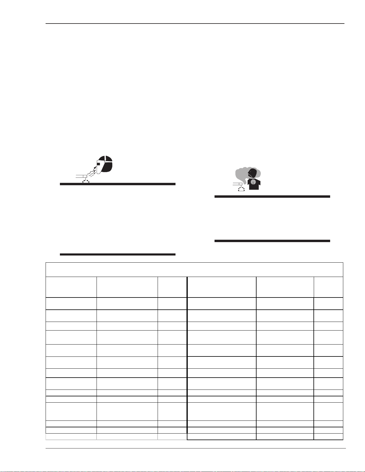
SELECTION DES NUANCES DE FILTRES OCULAIRS POUR LA PROTECTION
DES YEUX EN COUPAGE ET SOUDAGE (selon AWS á 8.2-73)
Opération de coupage
ou soudage
Brassage tendre
au chalumeau
Brassage fort
au chalumeau
Oxycoupage métaux ferreux toutes conditions 12
moyen de 1 á 6 po. (25 á 150 mm) 4 ou 5
Soudage aux gaz Soudage á l'arc Plasm a (PAW) toutes dimens ions 12
moyen de 1/8 á 1/2 po. (3 á 12 mm ) 5 ou 6 mince 12
Soudage á l'arc avec
électrode enrobees
(SMAW)
Dimens ion d'électrode ou
Epiasseur de métal ou
Intens ité de courant
toutes conditions 2
toutes conditions 3 ou 4 m étaux non-ferreux toutes conditions 11
mince m oins de 1 po. (25 mm) 2 ou 3
épais plus de 6 po. (150 mm) 5 ou 6
mince m oins de 1/8 po. (3 m m) 4 ou 5
épais plus de 1/2 po. (12 mm) 6 ou 8 épais 14
moins de 5/32 po. (4 mm) 10 Coupage á l'arc Plasma (PAC)
5/32 á 1/4 po. (4 á 6.4 mm) 12 mince moins de 300 amperès 9
plus de 1/4 po. (6.4 mm ) 14 moyen de 300 á 400 amperès 12
Nuance de
filtre oculaire
Opération de coupage
ou soudage
Soudage á l'arc s ous gaz
avec fil plein (GMAW)
Soudage á l'arc s ous gaz avec
électrode de tungstène (GTAW)
Soudage á l'hydrogène
atom ique (AHW)
Soudage á l'arc avec
électrode de carbone (CAW)
Gougeage Air-Arc avec
électrode de carbone
Dimens ion d'électrode ou
Epiasseur de métal ou
Intens ité de courant
toutes conditions 12
toutes conditions 12
toutes conditions 12
épais plus de 400 amperès 14
Nuance de
filtre oculaire
July 27, 2005
1-7
Page 14
HMC-410
1. Eloignez la tête des fumées pour éviter de les respirer.
2. A l’intérieur, assurez-vous que l’aire de soudage est
bien ventilée ou que les fumées et les vapeurs sont
aspirées à l’arc.
3. Si la ventilation est inadequate, portez un respirateur
à adduction d’air approuvé.
4. Lisez les fiches signalétiques et les consignes du
fabricant relatives aux métaux, aux produits
consummables, aux revêtements et aux produits
nettoyants.
5. Ne travaillez dans un espace confiné que s’il est bien
ventilé; sinon, portez un respirateur à adduction d’air.
Les gaz protecteurs de soudage peuvent déplacer
l’oxygène de l’air et ainsi causer des malaises ou la
mort. Assurez-vous que l’air est propre à la respiration.
6. Ne soudez pas à proximité d’opérations de
dégraissage, de nettoyage ou de pulvérisation. La
chaleur et les rayons de l’arc peuvent réagir avec des
vapeurs et former des gaz hautement toxiques et irritants.
7. Ne soudez des tôles galvanisées ou plaquées au plomb
ou au cadmium que si les zones à souder ont été
grattées à fond, que si l’espace est bien ventilé; si
nécessaire portez un respirateur à adduction d’air. Car
ces revêtements et tout métal qui contient ces
éléments peuvent dégager des fumées toxiques au
moment du soudage.
1. Protégez-vous, ainsi que les autres, contre les
étincelles et du métal chaud.
2. Ne soudez pas dans un endroit où des particules
volantes ou des projections peuvent atteindre des
matériaux inflammables.
3. Enlevez toutes matières inflammables dans un rayon
de 10, 7 mètres autour de l’arc, ou couvrez-les
soigneusement avec des bâches approuvées.
4. Méfiez-vous des projections brulantes de soudage
susceptibles de pénétrer dans des aires adjacentes
par de petites ouvertures ou fissures.
5. Méfiez-vous des incendies et gardez un extincteur à
portée de la main.
6. N’oubliez pas qu’une soudure réalisée sur un plafond,
un plancher, une cloison ou une paroi peut enflammer
l’autre côté.
7. Ne soudez pas un récipient fermé, tel un réservoir ou
un baril.
8. Connectez le câble de soudage le plus près possible
de la zone de soudage pour empêcher le courant de
suivre un long parcours inconnu, et prévenir ainsi les
risques d’électrocution et d’incendie.
9. Ne dégelez pas les tuyaux avec un source de courant.
10.Otez l’électrode du porte-électrode ou coupez le fil au
tube-contact lorsqu’inutilisé après le soudage.
11.Portez des vêtements protecteurs non huileux, tels
des gants en cuir, une chemise épaisse, un pantalon
revers, des bottines de sécurité et un casque.
AVERTISSEMENT
LE SOUDAGE PEUT CAUSER UN INCENDIE OU
UNE EXPLOSION
L’arc produit des étincellies et des projections.
Les particules volantes, le métal chaud, les
projections de soudure et l’équipement
surchauffé peuvent causer un incendie et des
brûlures. Le contact accidentel de l’électrode
ou du fil-électrode avec un objet métallique
peut provoquer des étincelles, un
échauffement ou un incendie.
1-8
AVERTISSEMENT
LES ETINCELLES ET LES PROJECTIONS
BRULANTES PEUVENT CAUSER DES
BLESSURES.
Le piquage et le meulage produisent des
particules métalliques volantes. En
refroidissant, la soudure peut projeter du
éclats de laitier.
1. Portez un écran facial ou des lunettes protectrices
approuvées. Des écrans latéraux sont
recommandés.
2. Portez des vêtements appropriés pour protéger
la peau.
July 27, 2005
Page 15
HMC-410
1. Utilisez l’équipement à l’extérieur dans des aires
ouvertes et bien ventilées.
AVERTISSEMENT
LES BOUTEILLES ENDOMMAGEES PEUVENT
EXPLOSER
Les bouteilles contiennent des gaz protecteurs
sous haute pression. Des bouteilles
endommagées peuvent exploser. Comme les
bouteilles font normalement partie du procédé
de soudage, traitez-les avec soin.
1. Protégez les bouteilles de gaz comprimé contre les
sources de chaleur intense, les chocs et les arcs de
soudage.
2. Enchainez verticalement les bouteilles à un support
ou à un cadre fixe pour les empêcher de tomber ou
d’être renversées.
3. Eloignez les bouteilles de tout circuit électrique ou de
tout soudage.
4. Empêchez tout contact entre une bouteille et une
électrode de soudage.
2. Si vous utilisez ces équipements dans un endroit
confiné, les fumées d’échappement doivent être
envoyées à l’extérieur, loin des prises d’air du bâtiment.
AVERTISSEMENT
LE CARBURANT PEUR CAUSER UN INCENDIE
OU UNE EXPLOSION.
Le carburant est hautement inflammable.
1. Arrêtez le moteur avant de vérifier le niveau e
carburant ou de faire le plein.
2. Ne faites pas le plein en fumant ou proche d’une source
d’étincelles ou d’une flamme nue.
3. Si c’est possible, laissez le moteur refroidir avant de
faire le plein de carburant ou d’en vérifier le niveau au
début du soudage.
4. Ne faites pas le plein de carburant à ras bord: prévoyez
de l’espace pour son expansion.
5. N’utilisez que des bouteilles de gaz protecteur, des
détendeurs, des boyauxs et des raccords conçus pour
chaque application spécifique; ces équipements et les
pièces connexes doivent être maintenus en bon état.
6. Ne placez pas le visage face à l’ouverture du robinet
de la bouteille lors de son ouverture.
7. Laissez en place le chapeau de bouteille sauf si en
utilisation ou lorsque raccordé pour utilisation.
8. Lisez et respectez les consignes relatives aux bouteilles
de gaz comprimé et aux équipements connexes, ainsi
que la publication P-1 de la CGA, identifiée dans la
liste de documents ci-dessous.
AVERTISSEMENT
LES MOTEURS PEUVENT ETRE DANGEREUX
LES GAZ D’ECHAPPEMENT DES MOTEURS
PEUVENT ETRE MORTELS.
5. Faites attention de ne pas renverser de carburant.
Nettoyez tout carburant renversé avant de faire
démarrer le moteur.
AVERTISSEMENT
DES PIECES EN MOUVEMENT PEUVENT
CAUSER DES BLESSURES.
Des pièces en mouvement, tels des
ventilateurs, des rotors et des courroies
peuvent couper doigts et mains, ou accrocher
des vêtements amples.
1. Assurez-vous que les portes, les panneaux, les capots
et les protecteurs soient bien fermés.
2. Avant d’installer ou de connecter un système, arrêtez
le moteur.
3. Seules des personnes qualifiées doivent démonter des
protecteurs ou des capots pour faire l’entretien ou le
dépannage nécessaire.
Les moteurs produisent des gaz d’échappement nocifs.
July 27, 2005
1-9
Page 16
HMC-410
4. Pour empêcher un démarrage accidentel pendant
l’entretien, débranchez le câble d’accumulateur à la
borne négative.
5. N’approchez pas les mains ou les cheveux de pièces
en mouvement; elles peuvent aussi accrocher des
vêtements amples et des outils.
6. Réinstallez les capots ou les protecteurs et fermez les
portes après des travaux d’entretien et avant de faire
démarrer le moteur.
AVERTISSEMENT
DES ETINCELLES PEUVENT FAIRE EXPLOSER
UN ACCUMULATEUR; L’ELECTROLYTE D’UN
ACCUMU-LATEUR PEUT BRULER LA PEAU ET
LES YEUX.
Les accumulateurs contiennent de l’électrolyte
acide et dégagent des vapeurs explosives.
1. Portez toujours un écran facial en travaillant sur un
accumu-lateur.
AVERTISSEMENT
LA VAPEUR ET LE LIQUIDE DE
REFROIDISSEMENT BRULANT SOUS
PRESSION PEUVENT BRULER LA PEAU ET
LES YEUX.
Le liquide de refroidissement d’un radiateur
peut être brûlant et sous pression.
1. N’ôtez pas le bouchon de radiateur tant que le moteur
n’est pas refroidi.
2. Mettez des gants et posez un torchon sur le bouchon
pour l’ôter.
3. Laissez la pression s’échapper avant d’ôter
complètement le bouchon.
1.05 PRINCIPALES NORMES DE
SECURITE
2. Arrêtez le moteur avant de connecter ou de
déconnecter des câbles d’accumulateur.
3. N’utilisez que des outils anti-étincelles pour travailler
sur un accumulateur.
4. N’utilisez pas une source de courant de soudage pour
charger un accumulateur ou survolter
momentanément un véhicule.
5. Utilisez la polarité correcte (+ et –) de l’accumulateur.
Safety in Welding and Cutting, norme ANSI Z49.1, American
Welding Society, 550 N.W. LeJeune Rd., Miami, FL 33128.
Safety and Health Standards, OSHA 29 CFR 1910, Superintendent
of Documents, U.S. Government Printing Office, Washington, D.C.
20402.
Recommended Safe Practices for the Preparation for Welding and
Cutting of Containers That Have Held Hazardous Substances,
norme AWS F4.1, American Welding Society, 550 N.W. LeJeune
Rd., Miami, FL 33128.
National Electrical Code, norme 70 NFPA, National Fire Protection
Association, Batterymarch Park, Quincy, MA 02269.
Safe Handling of Compressed Gases in Cylinders, document P-1,
Compressed Gas Association, 1235 Jefferson Davis Highway, Suite
501, Arlington, VA 22202.
Code for Safety in Welding and Cutting, norme CSA W117.2
Association canadienne de normalisation, Standards Sales, 276
Rexdale Boulevard, Rexdale, Ontario, Canada M9W 1R3.
Safe Practices for Occupation and Educational Eye and Face
Protection, norme ANSI Z87.1, American National Standards
Institute, 1430 Broadway, New York, NY 10018.
Cutting and Welding Processes, norme 51B NFPA, National Fire
Protection Association, Batterymarch Park, Quincy, MA 02269.
1-10
July 27, 2005
Page 17

HMC-410
1.06 DECLARATION OF CONFORMITY
Manufacturer: Thermadyne Corporation
Address: 82 Benning Street
West Lebanon, New Hampshire 03784
USA
The equipment described in this manual conforms to all applicable aspects and regulations of the ‘Low Voltage
Directive’ (European Council Directive 73/23/EEC as amended by Council Directive 93/68/EEC) and to the National
legislation for the enforcement of this Directive.
The equipment described in this manual conforms to all applicable aspects and regulations of the “EMC Directive”
(European Council Directive 89/336/EEC) and to the National legislation for the enforcement of this Directive.
Serial numbers are unique with each individual piece of equipment and details description, parts used to manufacture
a unit and date of manufacture.
National Standard and Technical Specifications
The product is designed and manufactured to a number of standards and technical requirements. Among them are:
• CSA (Canadian Standards Association) standard C22.2 number 60 for Arc welding equipment.
• UL (Underwriters Laboratory) rating 94VO flammability testing for all printed-circuit boards used.
• CENELEC EN50199 EMC Product Standard for Arc Welding Equipment.
• ISO/IEC 60974-1 (BS 638-PT10) (EN 60 974-1) (EN50192) (EN50078) applicable to plasma cutting
equipment and associated accessories.
• For environments with increased hazard of electrical shock, Power Supplies bearing the S mark conform to
EN50192 when used in conjunction with hand torches with exposed cutting tips, if equipped with properly
installed standoff guides.
• Extensive product design verification is conducted at the manufacturing facility as part of the routine design and
manufacturing process. This is to ensure the product is safe, when used according to instructions in this manual
and related industry standards, and performs as specified. Rigorous testing is incorporated into the manufacturing process to ensure the manufactured product meets or exceeds all design specifications.
Thermadyne has been manufacturing products for more than 30 years, and will continue to achieve excellence in our
area of manufacture.
Manufacturers responsible representative:
Steve Ward
Operations Director
Thermadyne Europe
Europa Building
Chorley N Industrial Park
Chorley, Lancashire,
England PR6 7BX
July 27, 2005
1-11
Page 18

HMC-410
1.07 LIMITED WARRANTY
LIMITED WARRANTY: Thermal Arc®, Inc., A Thermadyne Company, hereafter, “Thermal Arc” warrants to customers of itsauthorized distributors
hereafter “Purchaser” that its products will be free of defects in workmanship or material. Should anyfailure to conform to this warranty appear within
the time period applicable to the Thermal Arc products as stated below, Thermal Arc shall, upon notification thereof and substantiation that the product
has been stored, installed, operated, and maintained in accordance with Thermal Arc’s specifications, instructions, recommendations and recognized
standard industry practice, and not subject to misuse, repair, neglect, alteration, or accident, correct such defects by suitable repair or replacement, at
Thermal Arc’s sole option, of any components or parts of the product determined by Thermal Arc to be defective.
THERMAL ARC MAKES NO OTHER WARRANTY, EXPRESS OR IMPLIED. THIS WARRANTY IS EXCLUSIVE AND IN LIEU OF ALL OTHERS, INCLUDING,
BUT NOT LIMITED TO ANY WARRANTY OF MERCHANTABILITY OR FITNESS FOR ANY PARTICULAR PURPOSE.
LIMITATION OF LIABILITY: THERMAL ARC SHALL NOT UNDER ANY CIRCUMSTANCES BE LIABLE FOR SPECIAL, INDIRECT OR CONSEQUENTIAL
DAMAGES, SUCH AS, BUT NOT LIMITED TO, LOST PROFITS AND BUSINESS INTERRUPTION. The remedies of the Purchaser set forth herein are
exclusive and the liability of Thermal Arc with respect to any contract, or anything done in connection therewith such as the performance or breach
thereof, or from the manufacture, sale, delivery, resale, or use of any goods covered by or furnished by Thermal Arc whether arising out of contract,
negligence, strict tort, or under any warranty, or otherwise, shall not, except as expressly provided herein, exceed the price of the goods upon which
such liability is based. No employee, agent, or representative of Thermal Arc is authorized to change this warranty in any way or grant any other
warranty.
PURCHASER’S RIGHTS UNDER THIS WARRANTY ARE VOID IF REPLACEMENT PARTS OR ACCESSORIES ARE USED WHICH IN THERMAL ARC’S SOLE
JUDGEMENT MAY IMPAIR THE SAFETY OR PERFORMANCE OF ANY THERMAL ARC PRODUCT. PURCHASER’S RIGHTS UNDER THIS WARRANTY ARE
VOID IF THE PRODUCT IS SOLD TO PURCHASER BY NON-AUTHORIZED PERSONS.
The warranty is effective for the time stated below beginning on the date that the authorized distributor delivers the products to the Purchaser.
Notwithstanding the foregoing, in no event shall the warranty period extend more than the time stated plus one year from the date Thermal Arc
delivered the product to the authorized distributor.
POWER SUPPLIES
MAIN POWER MAGNETICS (STATIC & ROTATING) 3 YEARS 3 YEAR
ORIGINAL MAIN POWER RECTIFIER 3 YEARS 3 YEAR
CONTROL PC BOARD 3 YEARS 3 YEAR
ALL OTHER CIRCUITS AND COMPONENTS INCLUDING BUT
NOT LIMITED TO: CONTACTORS, RELAYS, SOLENOIDS, PUMPS,
POWER SWITCHING SEMI-CONDUCTORS.
ENGINES: ENGINES ARE NOT WARRANTED BY THERMAL ARC,
ALTHOUGH MOST ARE WARRANTED BY THE ENGINE
MANUFACTURER. SEE THE ENGINE MANUFACTURE'S 1 YEAR 1 YEAR
WAR RANTY FOR D ETAILS.
CONSOLES, CONTROL EQUIPMENT, HEAT EXCHANGES
ACCESSORY EQUIPMENT
NOTE: Dragster 85® excluded from this policy. Refer to Dragster 85 warranty in Dragster 85 Owner’s Manual.
Warranty repairs or replacement claims under this limited warranty must be submitted to Thermal Arc by an authorized Thermal Arc repair facility
within thirty (30) days of purchaser’s notice of any Warranty Claim. No transportation costs of any kind will be paid under this warranty. Transportation
charges to send products to an authorized warranty repair facility shall be the responsibility of the Purchaser. All returned goods shall be at the
Purchaser’s risk and expense. This warranty supersedes all previous Thermal Arc warranties. Thermal Arc® is a Registered Trademark of Thermadyne
Industries Inc.
September 27, 2004
ALL OTHER
POWER SUPPLIES
1 YEAR 1 YEAR
LABOR
1-12
July 27, 2005
Page 19

HMC-410
SECTION 2:
INTRODUCTION
2.01 How To Use This Manual
This Owner’s Manual applies to just specification or part
numbers listed on page i.
To ensure safe operation, read the entire manual, including
the chapter on safety instructions and warnings.
Throughout this manual, the words WARNING,
CAUTION, and NOTE may appear. Pay particular attention
to the information provided under these headings. These
special annotations are easily recognized as
follows:
WARNING
A WARNING gives information regarding
possible personal injury.
2.02 Equipment Identification
The unit’s identification number (specification or part
number), model, and serial number usually appear on a
nameplate attached to the control panel. In some cases,
the nameplate may be attached to the rear panel.
Equipment which does not have a control panel such as
gun and cable assemblies is identified only by the
specification or part number printed on the shipping
container. Record these numbers on the bottom of page
1 for future reference.
2.03 Receipt Of Equipment
When you receive the equipment, check it against the
invoice to make sure it is complete and inspect the
equipment for possible damage due to shipping. If there
is any damage, notify the carrier immediately to file a
claim. Furnish complete information concerning damage
claims or shipping errors to the location in your area
listed in the inside back cover of this manual.
Include all equipment identification numbers as described
above along with a full description of the parts in error.
CAUTION
A CAUTION refers to possible equipment
damage.
NOTE
A NOTE offers helpful information concerning
certain operating procedures.
Additional copies of this manual may be purchased by
contacting Thermal Arc at the address and phone number
given in the next section. Include the Owner’s Manual
number and equipment identification numbers.
Electronic copies of this manual can also be downloaded
at no charge in Acrobat PDF format by going to the
Thermal Arc web site listed below and clicking on the
Literature Library link:
http://www.thermalarc.com
Move the equipment to the installation site before uncrating the unit. Use care to avoid damaging the
equipment when using bars, hammers, etc., to un-crate
the unit.
July 27, 2005
2-1
Page 20
HMC-410
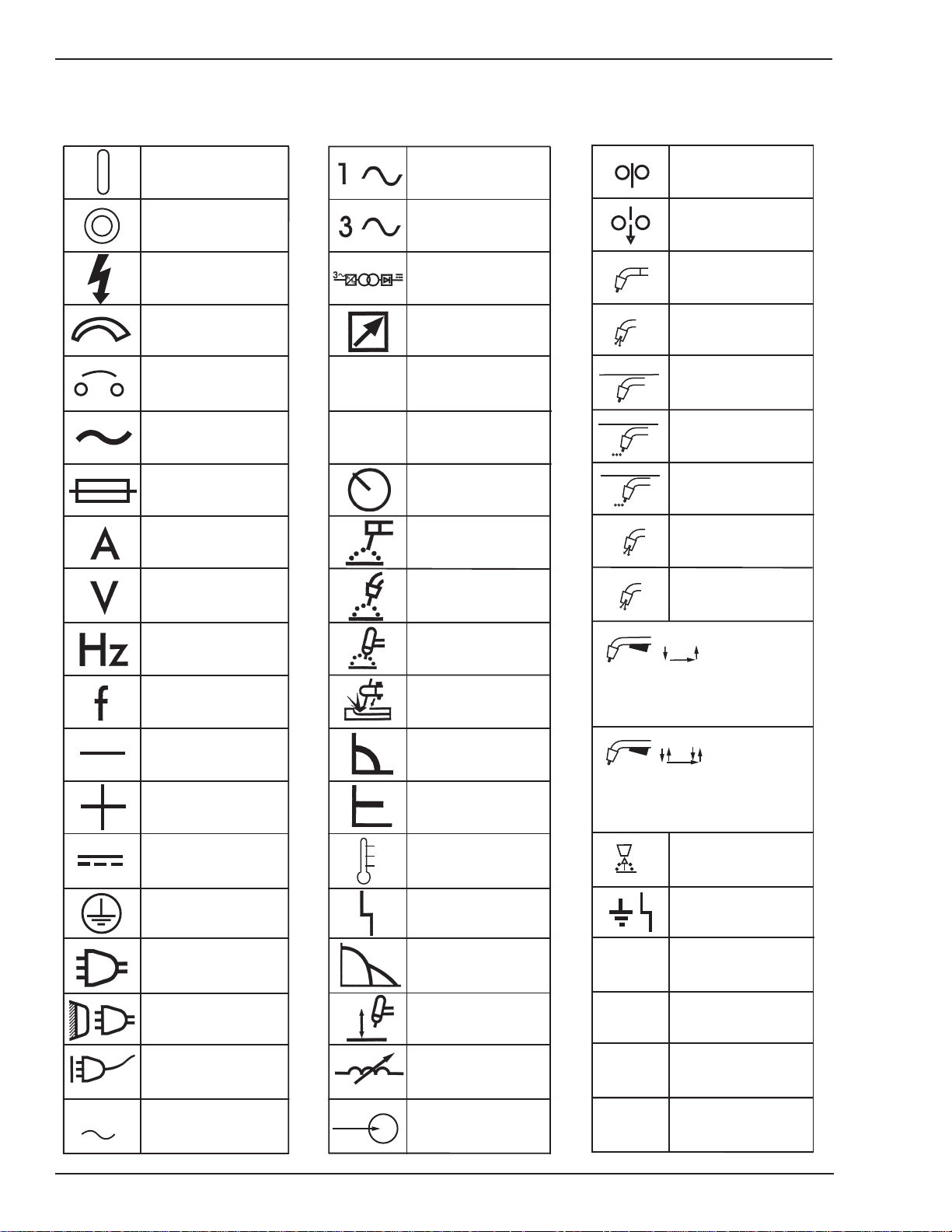
2.04 Symbol Chart
Note that only some of these symbols will appear on your model.
On
Off
Dangerous Voltage
Increase/Decrease
Circuit Breaker
AC Auxiliary Power
Fuse
Amperage
Voltage
X
%
Single Phase
Three Phase
Three Phase Static
Frequency ConverterTransformer-Rectifier
Remote
Duty Cycle
Percentage
Panel/Local
Shielded Metal
Arc Welding (SMAW)
Gas Metal Arc
Welding (GMAW)
Wire Feed Function
Wire Feed Towards
Workpiece With
t1
Output Voltage Off.
Welding Gun
Purging Of Gas
Continuous Weld
Mode
Spot Weld Mode
Spot Time
t
Preflow Time
Postflow Time
t2
Hertz (cycles/sec)
Frequency
Negative
Positive
Direct Current (DC)
Protective Earth
(Ground)
Line
Line Connection
Auxiliary Power
Gas Tungsten Arc
Welding (GTAW)
Air Carbon Arc
Cutting (CAC-A)
Constant Current
Constant Voltage
Or Constant Potential
High Temperature
Fault Indication
Arc Force
Touch Start (GTAW)
Variable Inductance
2 Step Trigger
Operation
Press to initiate wirefeed and
welding, release to stop.
4 Step Trigger
Operation
Press and hold for preflow, release
to start arc. Press to stop arc, and
hold for preflow.
Burnback Time
t
Disturbance In
Ground System
IPM
MPM
Inches Per Minute
Meters Per Minute
115V 15A
2-2
Receptacle RatingAuxiliary Power
Voltage Input
V
Art # A-04130
July 27, 2005
Page 21

HMC-410
2.05 General Information
The HMC-410 is an automatic/semiautomatic control
panel capable of precisely controlling a power source
(welding machine), wire feed motor, gas valve solenoid,
and if present an automatic fixture. The HMC-410 can be
controlled from the front panel or remotely through an
optional remote pendant assembly, optional auxiliary
interface cable, or optional robotic interface (see HMC410 Accessories And Option Descriptions chapter for
more details). The functional capability of the HMC-410
can be changed to meet more specific customer
applications by changing the system’s software. The HMC410 divides the weld process (schedule) into ready,
preflow, run in, weld, crater fill, burnback, post-flow, and
recycle segments. The user can program the appropriate
parameters (time, voltage, and wire feed speed) into each
segment. The HMC- 410 can store up to 10 weld schedules
in nonvolatile memory (schedules are saved even with
input power removed)
The HMC-410 comes with an abundance of standard
features which include:
• an on/off rocker switch with built-in circuit breaker
for total system protection
• a weld/program key switch for operator lockout
• an inch switch
• a solid state circuit providing current limit to the
wire feed motor
• a solid state dynamic brake.
The HMC-410 has been designed to comply with CSA
NRTL/C, NEMA EW 3, and CE (IEC974-5) standards.
2.06 Product Specifications
HMC-410 Specifications
Input Voltage: 120 VAC
Input Frequency: 50/60 Hz
Input Voltage Tolerance ±10%
Maximum Input Current 4.0 Amps
Number of Weld Schedules 10
Number of Weld Sub Segments
(per Schedule)
Maximum Auxilliary Relay Rating 4
Approvals
Table 2-1: Specification Chart
Refer to sheet 2 of the System Outline Drawing (number
170921) in the Appendix section of this manual for
dimensional information.
4
CSA NRTL/C
NEMA EW 3
CE (IEC974-5)
• a purge switch
• a test mode switch allowing a run through of a
programmed weld sequence setup without welding
• continuous-turn encoders for precise parameter
input
• numerous LED displays for visual indication of
parameters and modes
• a special soft switch screen allowing custom
programming of system capabilities
• software upgrades to tailor the performance and
capability of the system
• a self-diagnostics routine to aid in servicing
• a remote pendant amphenol input
• an auxiliary amphenol input for connection to PLC
controllers or other fixturing
• a tachometer feedback control loop for precise wire
feed speed control
• onboard fuses for system protection
• a ground fault circuit to protect the operator and
equipment from welding current flowing through
the ground system of the control panel
July 27, 2005
2-3
Page 22

HMC-410
p
y
Features Benefits
1. Solid State Circuitry
2. Tachometer Feedback
3. Continuous-Turn Encoders A. Allows precise input of welding parameters
4. Multiple LED Displays A. Provides visual indication of parameter input
5. Inch Switch A. Allows “cold” inching of wire at set wire feed speed
6. Purge Switch A. Allows purging of gas without running wire
7. Test Switch
8. Keyswitch A. Provides operator lockout to preset welding parameters
HMC-410 Features & Benefits
A. Provides input voltage compensation
B. Provides current limit to the motor
C. Provides overcurrent shutdown
A. Provides
recise wire feed speed accurac
B. Provides motor load compensation
A. Permits a practice run through of a programmed weld
sequence without welding
A. Operator can store up to 10 weld schedules into non-
9. 10 Weld Schedules
volatile memory for easy job changeover
B. Eliminates the need for continuous resetting of weld
parameters
10. Soft Switch Screen A. Allows custom programming of system capabilities
11. Self-Diagnostics Routine A. Aids in troubleshooting and servicing
12. Multiple Software Upgrades
13. Remote Pendant Amphenol
A. Permits a reconfiguration of system capabilities with a
simple change in software
A. Provides a connection point for the use of a remote
pendant control
A. Allows an easy interface to PLC’s or similar controllers
14. Auxiliary Interface Amphenol
B. Provides 3 system relays that can be used to provide
timing signals to PLC controllers
15. Dynamic Brake
A. Solid state control of a motor brake offers precise
stopping of the wire
16. Input Circuit Breaker A. Provides total system protection
17. On-Board Fuses A. Provides I/O protection
A. Protects the operator and equipment from welding
18. Ground Fault Circuit
current flowing through the ground system of the control
panel
2-4
19. 100% Duty Cycle A. Eliminates nuisance shutdowns due to overtemperature
20. Small Size/Light Weight A. Takes up small amount of space
Table 2-2: Features and Benefits
July 27, 2005
Page 23
HMC-410
July 27, 2005
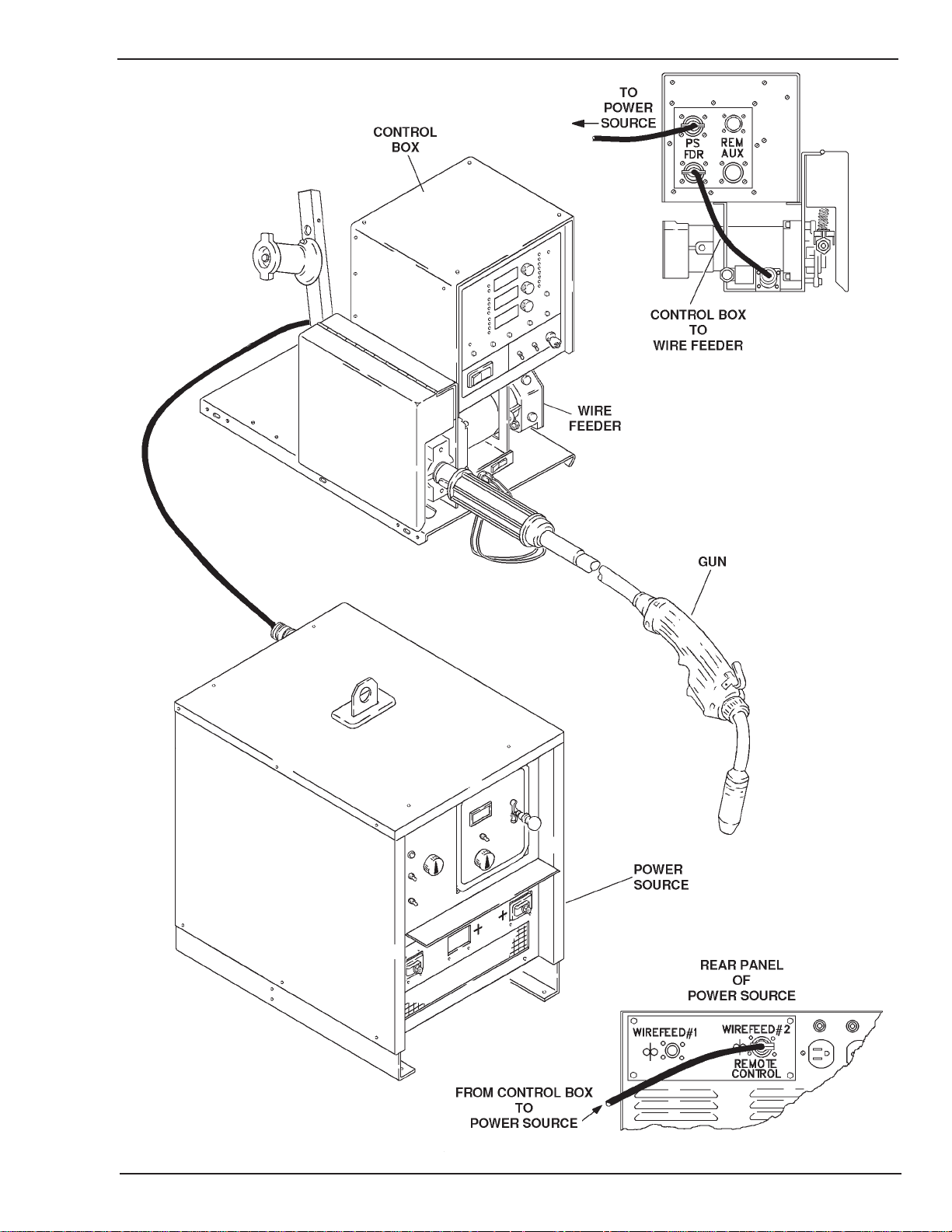
Art # A-04356
Figure 2-1A: Semiautomatic Configuration
2-5
Page 24
HMC-410
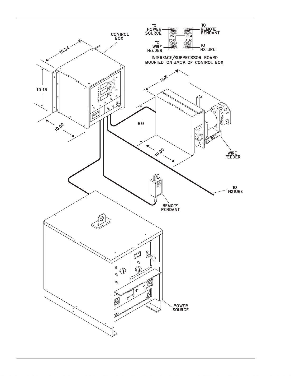
2-6
Art # A-04357
Figure 2-1B: Automatic Configuration
July 27, 2005
Page 25

HMC-410
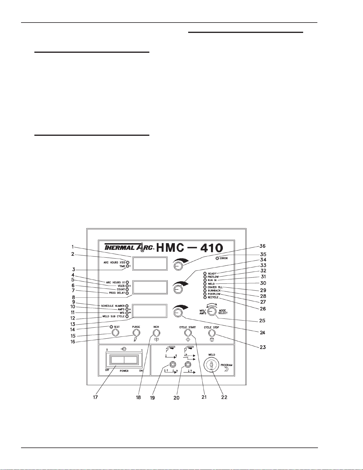
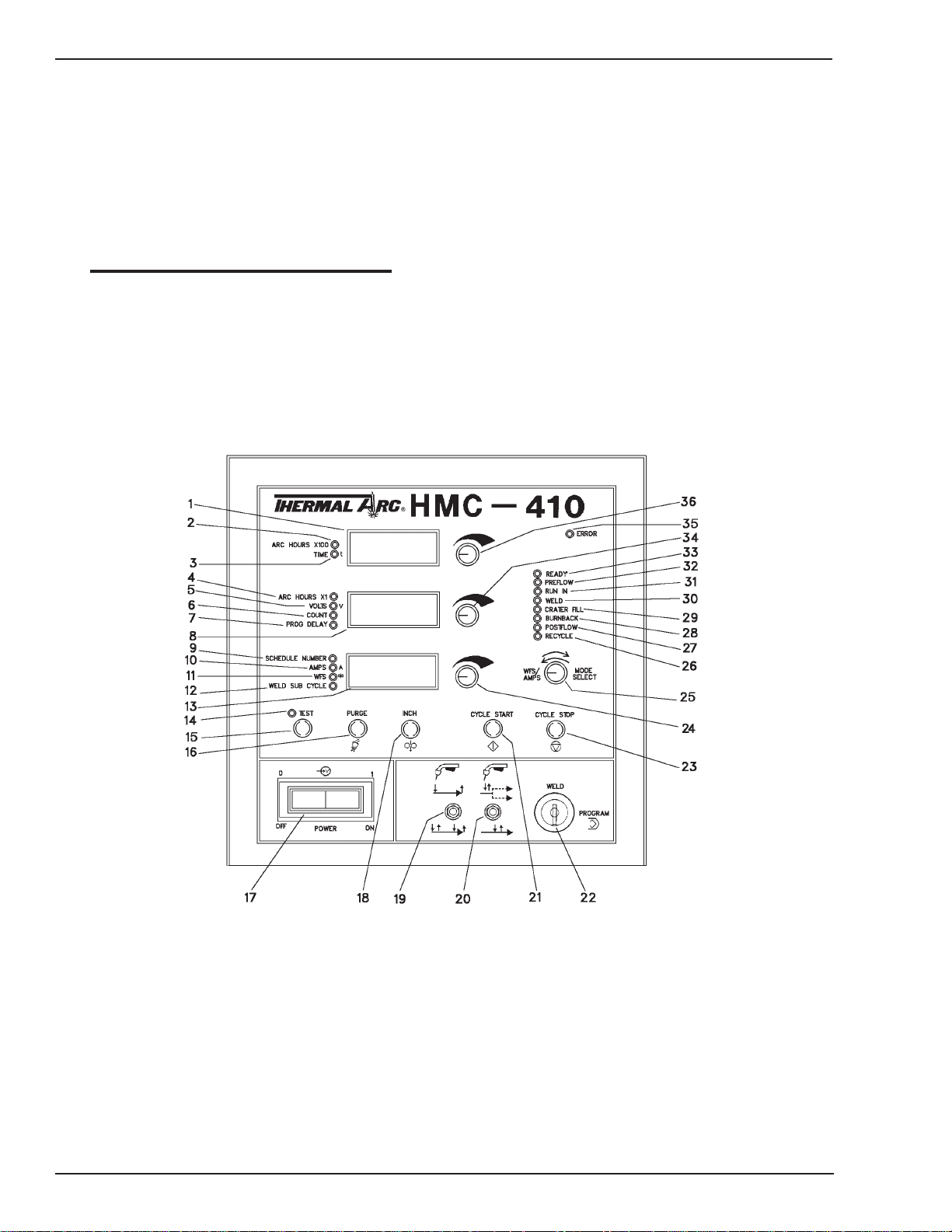
2.07 Front Panel Controls
Refer to Figure 2-2 for details.
1. UPPER DISPLAY — This display shows numerical
information for arc hours and time during normal
operation. It can also contain diagnostic test
information when diagnostics are performed.
2. ARC HOURS X100 LED—When lit, the upper display
will display the number of “hundreds of hours” the
control panel has controlled an arc. This number must
be added to the number of hours in the center display
for a total count of arc hours.
3. IME LED — When lit, the upper display will contain
the time, in seconds, of the selected segment.
4. ARC HOURS X1 LED — When lit, the center display
will show the number of hours the control panel has
controlled an arc. This number must be added to the
number of “hundreds of hours” in the upper display
for a total count of arc hours.
5. VOLTS LED —When lit, the center display will show
arc voltage. If the unit is being programmed, this
number represents the programmed arc voltage. If
the system is welding, this number is the actual arc
voltage.
NOTE
If the PSC softswitch is off, this LED will not
light. Refer to the Operation - Softswitch
Description chapter of this manual.
6. COUNT LED—When lit, the center display will
represent the number of weld sequence recycles. The
number displayed is the number of times the weld
sequence will repeat itself automatically. This number
can be 1 to 255.
7. PROG DELAY LED — When lit, the center display will
display the user selected programmable fault delay in
seconds.
NOTE
Refer to the Operation - Softswitch Description
chapter of this manual.
8. CENTER DISPLAY — This display shows numerical
information for arc hours, volts, count, and prog delay
during normal operation. It can also contain diagnostic
test information when diagnostics are performed.
9. SCHEDULE NUMBER LED — When lit, the lower display
will contain the schedule number currently active.
July 27, 2005
Art # A-04358
Figure 2-2: Front Panel Controls
2-7
Page 26
HMC-410
10.AMPS LED — When lit, the lower display will show
actual weld current in amps.
NOTE
To have the lower display show amps instead
of wire feed speed, the mode select encoder
will have to be turned.
11.WFS LED — When lit, the lower display shows the
wire feed speed. If the unit is being programmed, this
number represents the programmed wire feed speed.
If the system is welding, the value displayed is actual
wire feed speed.
NOTE
The unit comes from the factory with the WFS
displayed in inches per minute (IPM). The WFS
can be displayed in meters per minute (MPM).
Refer to the Operation - Softswitch Description chapter of this manual.
12.WELD SUB SEGMENT LED — When lit, the lower display contains the current weld sub segment number.
The weld sub segment number may be from 1 to 4.
The system must be configured for weld sub segment
operation for this to be selectable.
NOTE
Refer to the Operation - Softswitch Description chapter of this manual.
13.LOWER DISPLAY — This display shows numerical
information for schedule number, amps, WFS, and
weld sub segment during normal operation. It can also
contain diagnostic test information when diagnostic
are performed.
14.TEST LED — When lit, the control panel is in a test
mode. The test mode allows the weld operator to perform the weld schedule with all of its control signals,
timing, and displayed voltages and wire feed speeds.
However the wire feeder and power source will not
operate.
15.TEST BUTTON — This button will toggle the control
panel in and out of test mode. This button has no
effect during a weld.
16.PURGE BUTTON — Depressing the purge button will
allow shielding gas to flow out of the welding gun
without feeding wire. This button has no effect during
a weld.
2-8
Art # A-04358
Figure 2-2: Front Panel Controls
July 27, 2005
Page 27

HMC-410
17. POWER ON/OFF SWITCH — This switch controls only
the control panel and not the power source (welding
machine). It is used as an on/off switch and also serves
as a circuit breaker. NOTE: If the circuit breaker trips,
it turns the power switch to the OFF position. A short
cooling period must be allowed before an attempt is
made to reset the unit by placing the switch in the ON
position.
18.INCH BUTTON—Depressing the inch button will feed
wire (without the flow of gas) at a speed programmed
into the Run In section of the weld schedule; the welding wire WILL NOT be electrically “hot”. This button
has no effect during a weld.
19. TRIGGER HOLD SWITCH (OPTIONAL) — This optional
switch selects either 2 Step or 4 Step gun switch mode
of operation for semiautomatic applications (to change
the operation of this switch, refer to the Operation Softswitch Description chapter of this manual). A detailed theory of operation for both modes of operation is given in the Operation chapter of this manual.
20. SUB SEGMENT ENABLE SWITCH (OPTIONAL) — This
optional switch disables or enables the sub segment
mode of operation for semiautomatic applications (to
change the operation of this switch, refer to the Operation - Softswitch Description chapter of this
manual). A detailed theory of operation for the sub
segment mode of operation is given in the Operation
chapter of this manual.
21.CYCLE START BUTTON — This button is used to start
the weld cycle. When pressed, the control panel advances to the preflow section of the weld cycle. Depressing this button while in a weld cycle has no effect.
22.PROGRAM/WELD SWITCH — When this switch is in
the program mode, weld parameters can be changed.
When this switch is in the weld mode, weld parameters cannot be changed.
NOTE
The functionality of this switch can be changed
in the softswitch screen and/or with different
software upgrades. Refer to the Operation and
Option chapters of this manual for further detail.
23.CYCLE STOP BUTTON—This button is used to stop a
front panel initiated weld cycle. When pressed, the
control panel leaves the weld section and enters the
crater fill section of the weld cycle. When a weld is
stopped with the cycle stop button, the control panel
skips over the recycle section of the weld cycle.
NOTE
Depressing this button ONLY stops the weld
cycle if the weld cycle was started with the
cycle start button. This button WILL NOT stop
a weld cycle that was started with a gun switch
closure, remote pendant, or auxiliary fixture.
24.LOWER ENCODER—This encoder changes parameters displayed in the lower display. Turning this encoder clockwise increases the value of the parameter
and counterclockwise decreases the value of the parameter.
25.MODE SELECT ENCODER — This encoder serves two
functions. While not welding, the encoder selects the
desired section of the weld cycle for parameter input
and viewing. While welding, the encoder selects
whether actual wire feed speed (WFS) or actual welding current (AMPS) is shown in the lower display.
26.RECYCLE LED — When lit, the control panel is in the
recycle section of the weld cycle.
27.POST-FLOW LED—When lit, the control panel is in
the post-flow section of the weld cycle.
28.BURNBACK LED—When lit, the control panel is in the
burnback section of the weld cycle.
29.CRATER FILL LED — When lit, the control panel is in
the crater fill section of the weld cycle.
30.WELD LED — When lit, the control panel is in the
weld section of the weld cycle.
31.RUN IN LED — When lit, the control panel is in the
run in section of the weld cycle.
32.Preflow LED — When lit, the control panel is in the
preflow section of the weld cycle.
33.READY LED — When lit, the control panel is in the
ready section of the weld cycle.
34.CENTER ENCODER — This encoder changes parameters displayed in the center display. Turning this encoder clockwise increases the value of the parameter
and counterclockwise decreases the value of the parameter.
NOTE
The (Arc Hours X1) information cannot be
changed with the center encoder. To reset the
count to 0, refer to the Operation - Softswitch
Description chapter of this manual.
July 27, 2005
2-9
Page 28
HMC-410
35. ERROR LED—When lit, the control panel has detected
an error. Refer to the Operation - Operational Faults
section of this manual.
36.UPPER ENCODER — This encoder changes
parameters displayed in the upper display. Turning this
encoder clockwise increases the value of the
parameter and counterclockwise decreases the value
of the parameter.
NOTE
The (Arc Hours X100) information cannot be
changed with the upper encoder. To reset the
count to 0, refer to the Operation - Softswitch
Description chapter of this manual
.
2-10
Art # A-04358
Figure 2-2: Front Panel Controls
July 27, 2005
Page 29
HMC-410
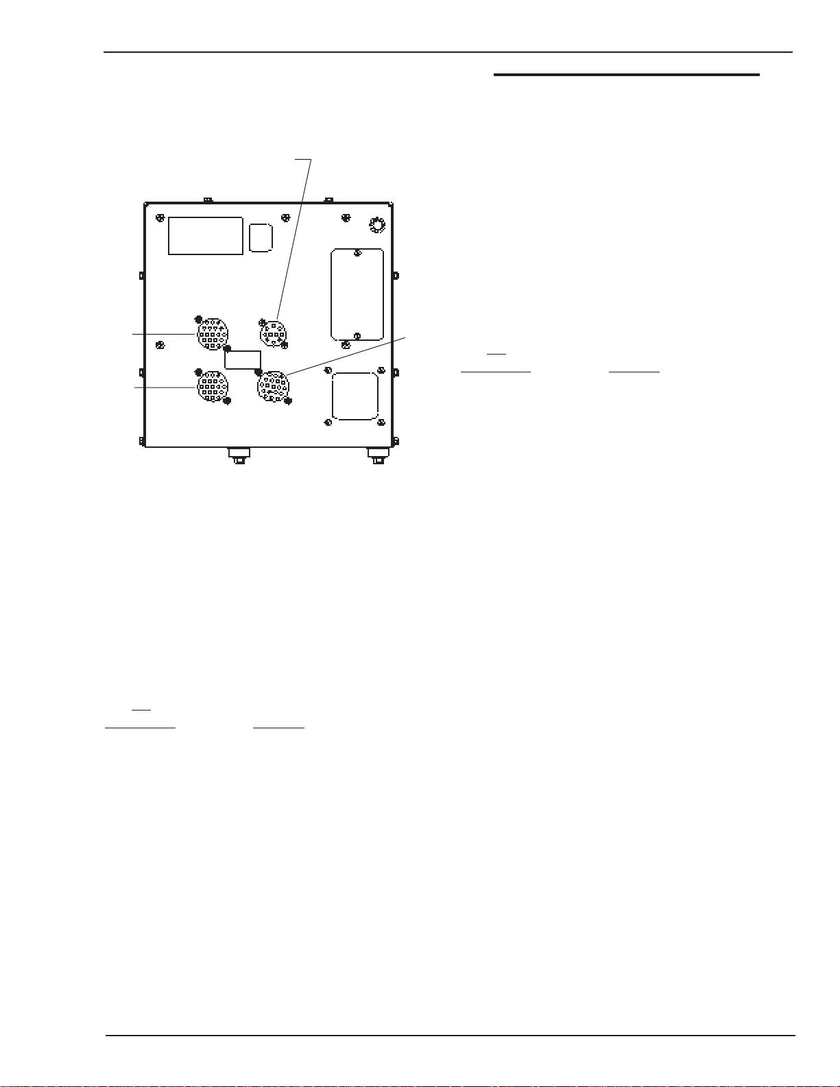
2.08 Rear Panel Connections
Refer to Figure 2-3 for details.
Remote Pendant
(See HMC-410 Accessories
And Option Descriptions)
37
38
Art # A-04359
Figure 2-3: Rear Panel Connections
37.POWER SOURCE AMPHENOL—This 19 pin male
amphenol serves as the interface between the HMC410 and power source. A control cable will have to be
connected between this amphenol and the 19 pin
amphenol on the power source (Refer to the HMC410 Accessories And Option Descriptions chapter of
this manual for control cable part numbers). The HMC410 utilizes the following pins of the 19 pin amphenol:
Pin
Assignment Function
39
NOTE
These pin assignments are for the HMC-410
only. Power source amphenol pin assignments
will differ slightly (Refer to the power source
owner’s manual for details).
38.FEEDHEAD AMPHENOL — This 19 pin female
amphenol serves as the interface between the HMC410 and feedhead assembly. A control cable will have
to be connected between this amphenol and the 19
pin amphenol on the feedhead assembly (refer to the
HMC-410 Accessories And Option Descriptions
chapter of this manual for control cable part numbers).
The HMC-410 utilizes the following pins of the 19 pin
amphenol:
Pin
Assignment Function
A (-) Motor Voltage
B (+) Motor Voltage
C Inch Enable Out
D Gun Switch Enable In
F Inch Enable In
G Chassis Ground
J Gas Valve Lo
M Tachometer Common
N Tachometer (+15 VDC)
P Tachometer Feedback Signal
T Gas Valve High
V Gun Switch Enable Out
39. AUXILIARY AMPHENOL—If used, this 19 pin male
amphenol would serve as the interface between the
HMC-410 and appropriate external fixture. An auxiliary
cable would have to be connected between this
amphenol and the fixture (Refer to the HMC-410
Accessories And Option Descriptions chapter of this
manual for auxiliary cable part numbers).
A Power Source Contactor Input
B Power Source Contactor Output
C Arc Volts (+)
D Arc Amps (+)
E 120 VAC High
F 120 VAC Neutral
G Chassis Ground
J Remote Voltage Control Reference
L Power Source Control Circuit Common
M Arc Established Signal Input
U Arc Amps (+)
V Arc Volts (-)
July 27, 2005
This amphenol would only be used in an automatic
application where the HMC-410 was to be controlled
from some type of external fixture. Through this
interface, the control panel accepts start, stop, inch,
purge, and sub segment advance commands from the
fixture and provides relay outputs to the fixture for
timing and error conditions. The HMC-410 utilizes the
following pins of the 19 pin amphenol (refer to Figure
3-4 for graphical assistance).
2-11
Page 30
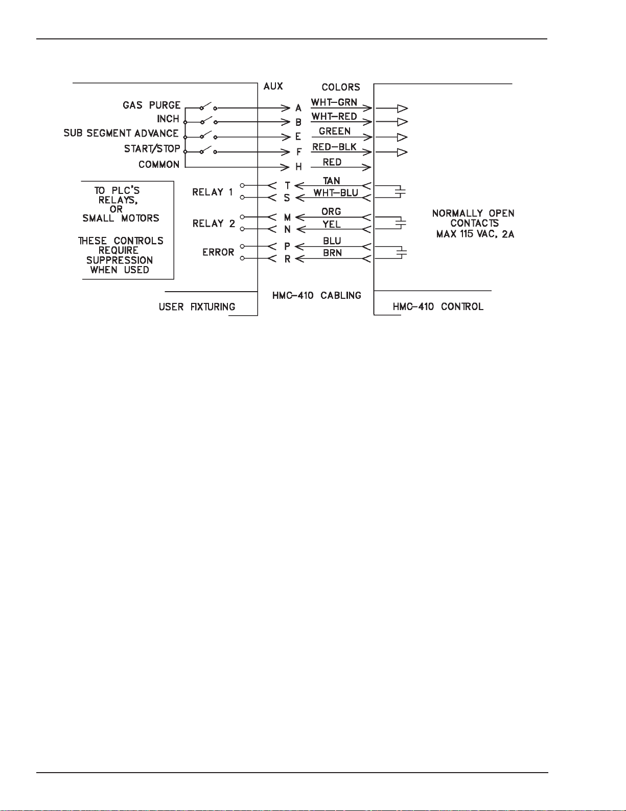
HMC-410
Art # A-04360
Figure 2-4: Fixture Electrical Interface
Pin A (Purge Input) —If connected to Pin H, the control
panel will allow the flow of gas without running wire.
Pin B (Inch Input) — If connected to Pin H, the control
panel will feed wire (without the flow of gas) at a speed
programmed into the Run In section of the weld cycle;
the welding wire WILL NOT be electrically “hot.”
Pin E (Sub Segment Advance Input) — Connecting
(momentarily or permanently) to Pin H will advance the
control panel to the next programmed weld sub segment
(i.e. 1 to 2, 2 to 3, 3 to 4, and 4 to 1). However, if
permanently connecting Pin E to Pin H, the connection
will have to be momentarily opened and then closed again
for another sub segment advance. Refer to the Operation
- Auxiliary Interface Operation or Semiautomatic
Operation section of this manual for specific details on
setup and operation of the sub segment feature.
Pin F (Start/Stop Input)— To start the weld cycle, connect
to Pin H. The control panel will then cycle from preflow to
weld. To stop the weld cycle, disconnect from Pin H. The
control panel will then leave weld and cycle from crater
fill to ready.
Pins M and N (Relay 2) — This relay is normally open.
When the control is in the recycle segment in between
spot welds or at end of continuous weld, the relay will
close (between pins M and N).
Pins P and R (Error Relay)—This relay is normally open.
When the control detects a tolerance or ground fault, the
relay will close (between pins P and R). The relay will
remain closed for the duration of the weld in which the
fault occurred, and .1 second into Ready. This relay can
be used to drive another relay to latch the occurrence of
an error. A tolerance fault can be one of: arc voltage out
of tolerance, wire feed speed out of tolerance, or loss of
arc established. The tolerance fault is reset when a new
weld is initiated.
Pins T and S (Relay 1) — This relay is normally open.
When the control is in the weld segment, the relay will
close (shorting pins T and S). This relay is used for an
arc on condition.
Pin H (Common) — This pin serves as the common for
pins A, B, E, and F.
2-12
July 27, 2005
Page 31

HMC-410
2.09 Power Source Interface Description
The power source interface is used to supply operating power to the control panel and for the panel to control the
power source output. The interface also provides arc voltage and current information to the panel.
The interface is shown in Figure 2-5.
July 27, 2005
Art # A-04361
Figure 2-5: Power Source Interface
2-13
Page 32

HMC-410
2.10 Hardware Description
The HMC-410 is comprised of five major subassemblies.
Each subassembly provides a distinct function, and
understanding these functions can be helpful in
understanding the operation of the HMC- 410. The
subassemblies are:
1. Enclosure/Cabling
2. Control/Display Printed Circuit Board PCB Assembly.
3. Power Supply/Motor Control PCB Assembly
4. Controller PCB Assembly
5. Interface/Suppression PCB Assembly
These assemblies will be described in the following text.
Enclosure/Cabling
The enclosure and cabling will be the assembly that the
equipment operator will be in most constant contact with.
The enclosure provides the safe isolation between the
internal circuitry and the outside world. The cabling allows
the internal circuitry to communicate with itself, as well
as to the equipment outside of the enclosure.
The cabling is shielded internally to limit susceptibility to
electrical noise. Keeping the cabling at a maximum
distance from electrical noisy devices (such as TIG
welders and high power lines) will also limit susceptibility
of the cabling (and the control) to noise.
The internal cabling interconnects the internal components
for proper operation of the control panel. Care has been
taken to choose interconnection systems that will provide
years of trouble-free operation. However, in cases of
jarring during shipping or use, it may be necessary to
occasionally re-seat these connectors.
Control/Display PCB Assembly
(Refer to Figure 2-6)
The Control/Display PCB (C/D Board) Assembly provides
the front panel controls and displays. It mounts directly
behind the front panel. Included on the C/D Board are the
numeric displays, light emitting diodes (LEDs), encoders
and pushbuttons. The C/D Board connects to the controller
board via a 26-position ribbon cable. The C/D Board
provides the controller board with encoder and button
status, and receives display data for the numeric and LED
displays.
The reason for the enclosure to isolate the circuitry is
twofold. First is to protect the operators from dangerous
signals which are present at various points inside the
panel. Second, the enclosure protects the internal circuitry
from damage and malfunction due to foreign objects and
external electrical emissions (noise). Both of these
functions are provided by having the whole chassis
electrically tied to earth ground. Because of this fact, it is
extremely critical that all chassis hardware is installed
when the panel is operating. The earth ground is provided
via the power source cable, pin G.
The enclosure also provides the operator with front panel
control of the panel. The power switch, toggle switches
(optional), control buttons, encoders, and displays are
all presented through the front panel. Care should be taken
to protect the front panel since many of these controls
are susceptible to damage.
The external cabling will interface the control with the
power source, wire feeder, a remote pendant (if present)
and user defined fixturing (as described in Rear Panel
Connections). The cabling is made of high durability
neoprene covering for long life. Care should be taken to
avoid damage to the cabling as that may cause safety
problems and possible damage to the equipment.
2-14
July 27, 2005
Page 33

HMC-410
Pushbuttons
LEDs
Numeric
Displays
Art # A-04362
Encoders
Figure 2-6: Control/Display PCB Assembly
July 27, 2005
2-15
Page 34

HMC-410
Power Supply/Motor Control PCB Assembly
(Refer to Figure 2-7)
The Power Supply/Motor Control PCB Assembly (PS/MC
Board) has two functions. It provides the various low
voltage control voltages used by the solid state circuitry
throughout the HMC-410. It also translates control signals
from the controller board into power for the motor.
The power supply section of the board utilizes the off
board transformer to divide the line voltage down to the
voltage levels used by the circuitry in the system. The
rough functionality of this circuitry can be performed by
visually inspecting the LEDs on the board. If the LED is
lit, then the voltage is at least approximately what it should
be. In order to verify the exact voltages, a meter can be
used on the following test points:
HI LO Expected Reading Status LED
TP1 TP2 –15 VDC (± .05 VDC) CR3
TP3 TP2 +5 VDC (± .5 VDC) CR7
TP4 TP2 +15 VDC 1 (± .05 VDC) CR2
NOTE
These measurements and repairs should be
performed only by a qualified electrical
technician.
The motor control circuitry drives the DC motor which
feeds the filler metal used in the MIG process. There are
various protection circuits which will disable the motor
control circuitry should it detect an excessive load on the
motor or control circuitry. Some of these protections
require that the panel’s power be cycled to reset them.
Also, the fuse F5 could blow should the motor current
exceed its limits. Should these shutdowns continuously
set, check that the filler metal can freely feed. If it is not
impeded, verify that the cabling is not damaged. The PS/
MC board interconnects to the transformer, the controller
board, and the interface/suppressor board.
TP5 TP7 +15 VDC 2 (± .5 VDC) CR9
TP6 TP7 +15 VDC UNREG CR8
(+25 to +35 VDC)
TP7 TP9 +12 VDC (±.5 VDC) CR17
CR9
2-16
Art # A-04363
Figure 2-7: Power Supply/Motor Control PCB Assembly
July 27, 2005
Page 35

HMC-410
THIS PAGE INTENTIONALLY LEFT BLANK
July 27, 2005
2-17
Page 36

HMC-410
Controller PCB Assembly
(Refer to Figure 2-8)
The Controller PCB Assembly (controller) is the main
control for the panel. It collects all of the data from the
various controls and interfaces and provides control
stimuli to all of the equipment under its control. This board
has five receptacles on it to interface with the other
systems. It also has two connectors which allow
expandability for future enhancements.
At the heart of the controller board is a Signetics 80C552
Microcontroller designed specifically for harsh
environments such as automotive and industrial
applications. This microcontroller, and its associated
software, drive the HMC-410 to perform its activities like
timing, conversion of voltages and currents to digital data
to be displayed by the C/D board, and the conversion of
programmed data into voltages used by the power source
and PS/MC board.
The controller interfaces with the C/D board presenting
data for display and collecting control switch states. The
controller interfaces with the PS/MC board by receiving
power from that board, and supplying control stimuli to
the motor control circuitry.
The controller also interfaces with the interface/
suppressor board. It sends relay closures to the interface/
suppressor board for use on the auxiliary interface, power
source, and gas valve. This interface supplies external
control switch states, arc voltage, arc current, and tach
information to the controller.
onto it. When replacing (or maintenance stocking), please
verify that this board also has the appropriate software
kit installed onto it.
Controller Board Test Points
(Refer to Figure 2-8)
This board was designed to survive in an industrial,
electrically noise heavy environment. There are several
test points on the board, but are typically only used for
initial test and calibrations of the board. The test points
are included here only as a reference.
TP1 Signal Common
TP2 Wire Feed Speed Control Voltage
TP3 +5 VDC
TP4 +10 VDC
TP5 WFS Tach Input
TP6 Power Source Control Voltage
TP7 Arc Current 5 VDC
TP8 Power Source Signature
TP9 Arc Voltage
TP10 +4.4 VDC
TP11 Arc Current
Controller Board Jumpers
(Refer to Figure 2-8)
Refer to Figure 2-8 for the following descriptions of the
controller board’s test points, jumpers, and DIP switch.
Controller Board Software
The controller may have optional software installed
onto it. This software can be installed in the field. The
software may be ordered as a 171238- dash number)
kit. Refer to the Options chapter for more information
on these software options.
Care must be exercised when ordering replacement
controller boards for systems that have had optional
software installed. New controller boards ordered from
the factory will ship with the standard software installed
There are three jumpers on the controller board. The
jumpers are used to configure the board for various
products that this panel may be used with. Jumper JP2
is used to select power source control voltage polarity.
Refer to System Configuration located in the Operation
chapter for power source compatibility. Jumper JP3 and
JP4 are used for voltage feedback. Refer to System
Configuration located in the Operation chapter for power
source compatibility.
2-18
July 27, 2005
Page 37

HMC-410
Art # A-04364
July 27, 2005
Figure 2-8: Controller Board Test Points and Jumpers
2-19
Page 38

HMC-410
Controller Board DIP Switch
These switches will normally be set to the open position.
All of these functions are controllable from the front panel
by the soft switches, described in the Operation chapter
of this manual.
The controller board also has a DIP switch (reference
designator number S1) which is used to configure the
board to operate in an application specific mode. The DIP
switch can be used to run the diagnostic routines. The
diagnostic selections are described in the Troubleshooting
chapter of this manual.
Art: A-05054
Figure 2-9: Dip Switch
Trigger Hold Enable — This DIP switch is enabled only
when the PdE soft switch is set to HAr. When this switch
is in the OPEN position, the Trigger Hold feature for
semiautomatic welding is enabled. When this switch is
CLOSED, the triggering mechanism is called deadman,
meaning that for the panel to continue welding, the switch
must continue to be pulled. The trigger hold feature allows
the welder to initiate the weld with a momentary pull of
the switch, and terminate the weld with another
momentary pull of the switch. The full description of this
process is described in the Semiautomatic section of the
Operation chapter of this manual. This feature can also
be selected from an optional switch on the front panel.
Interface/Suppressor PCB Assembly
(Refer to Figure 2-10)
The Interface/Suppressor PCB Assembly (I/S Board) is
the link between the external, Amphenol type connectors,
and the internal ribbon and discrete wire connectors.
Several signals are filtered in order to reduce electrical
noise coming into the control panel.
NOTE
OPEN is sometimes called ON or 1 and should
be considered the same state. Conversely, not
OPEN will be referred to as CLOSED, OFF, or
0.
Diagnostics Select — When this switch is in the CLOSED
position, the diagnostics routines are executed. These
routines are described in detail in the Troubleshooting
chapter of the manual. In order to use the control panel
operationally, this switch should be OPEN.
Weld Sub Segment Enable—This DIP switch is enabled
only when the SSE soft switch is set to HAr. When this
switch is in the OPEN position, the multiple Weld Sub
Segment feature of the control panel is enabled. This
feature is used to change the weld parameters because
of a discontinuity in the work. This feature is described in
the Semiautomatic Operation section and Auxiliary
Interface Operation section located in the Operation
chapter of this manual. When this switch is CLOSED, the
control panel will ignore instructions to use the next
sequential Weld Sub Segment parameters.
There are four jumpers on the I/S board. The jumpers are
used to configure the board for various products that this
panel may be used with. Refer to Figure 2-10 for jumper
locations.
100050-2 Specification HMC-410
The 100050-2 HMC-410 is a special configuration of the
HMC-410 that has an RS-232C interface installed into it
and the 171238-19 software kit installed into it. This
configuration has a 870200-2 board installed that provides
the RS-232C circuitry and a 9 pin D-Sub connector.
Contact the factory for additional information in using
the RS-232 interface.
2-20
July 27, 2005
Page 39

Front
View
HMC-410
Art # A-04365
Back
View
July 27, 2005
Figure 2-10: Interface/Suppressor PCB Assembly
2-21
Page 40

HMC-410
2-22
July 27, 2005
Page 41

HMC-410
SECTION 3:
INSTALLATION
3.01 Location
When selecting an installation site, take care to avoid
locations exposed to high ambient temperature, high
humidity, dust, or corrosive liquids or fumes. Moisture
condenses on electrical parts, causing corrosion or short
circuits. Dirt on parts retains moisture and increases wear
on moving parts.
3.02 Assembly
Components of this system are completely assembled at
the factory. When received at the job site, it will be
necessary to refer to instruction manuals and/or
instruction sheets for details on setup of the system in
which the controller is to be used. See TIPs supplied with
the manual for information on the feedhead, wire supply,
and cabling.
8. Connect the welding gun control leads to the wire
feeder gun switch terminals located on the front of
the feeder.
3.04 Load Suppression
The HMC-410 provides three relays on the auxiliary
amphenol connector for customer use, the ratings of these
relays are listed in the Description of Equipment chapter
of this manual. Proper load suppression will extend relay
life as well as minimize electromagnetic interference. Due
to the unique nature and requirements of each load, it is
required that the customer provide load suppression. The
following guidelines and Figure 3-1 are provided to help
with the selection of components.
Device Selection for AC Operation
Resistor — 0.5 to 1 Ohm per contact volts
Capacitor—0.5 to 1 Microfarad per contact amps
Use AC type capacitors (non-polarized) with a breakdown
voltage of 200 to 300 V. Always test your selection in
actual use.
3.03 Electrical Connections
See the System Outline drawing (170921) in the Appendix
chapter of this manual for details.
CAUTION:
Make sure all connections are tight; otherwise,
arcing or overheating could result.
1. Make the proper welding cable connections between
the power source and wire feeder and between the
power source and work connection.
2. Connect the power source control cable to the control
panel “PS” amphenol connector.
3. Connect a control cable between the wire feeder and
the control panel “FDR” amphenol connector.
4. Connect the remote pendant (if used) to the control
panel “REM” amphenol connector.
5. Connect a control cable (if used) between the PLC or
similar controller and the control panel “AUX”
amphenol connector.
Example:
An inductive load requiring 120 V AC, 1 Amp; the resistor
should be between 60 and 120 ohms, and the capacitor
between 0.5 and 1 microfarad with a 200 to 300 volt rating.
Art # A-04367
Figure 3-1: Load Suppression Schematic
6. Make the proper gas line connection from the gas
supply to the wire feeder gas valve (if gas will be used).
7. Attach the welding gun to the wire feeder.
July 27, 2005
3-1
Page 42

HMC-410
3.05 Grounding
The case of the HMC-410 control should be grounded for
personnel safety. Where grounding is mandatory under
state or local codes, it is the responsibility of the user to
comply with all applicable rules and regulations. Where
no state or local codes exist, it is recommended that the
National Electrical Code be followed.
The HMC-410 control like all solid-state equipment is
susceptible to EMI (electromagnetic interference). All
welding power sources and, in particular, TIG power
sources using high frequency arc stabilization are major
sources of EMI radiation. Care must be taken to minimize
interference through proper equipment grounding. The
chassis of the controller must be connected to a driven
ground(Figure 3-2) or a water pipe that enters the ground
not more than 10 feet from the equipment.
The ground lead should be as short as possible and a
minimum of #8 wire. This is normally accomplished by
grounding the power source chassis which is connected
to the controller chassis through the power source
interface cable.
CAUTION
Electromagnetic interference can cause the
HMC-410 to malfunction in unexpected ways.
Care should be taken when the HMC-410 is
used in motion control applications to provide
emergency shutdown in case of equipment
malfunction. Proper grounding techniques will
minimize the problem, however, an emergency
shutdown facility is still recommended.
3-2
Outside Ground
Art # A-04366
Inside Ground
Figure 3-2: Grounding Rod Installation
July 27, 2005
Page 43

HMC-410
SECTION 4:
OPERATION
This chapter is organized to guide the user from setup, to
power up, and to start up. The first section will direct the
user how to configure the HMC-410 control panel. The
second section will describe how to program the HMC410 for use. The third section will guide the integrator on
how to configure the system to be mated with the control
panel, i.e., feeder/torch, power source, and fixturing. The
fourth section will detail the operation of the HMC-410 in
its different modes of operation.
This entire chapter (and manual) should be read and
understood before any actual setup is performed. This
list is given in a general order of performance, but actual
order may vary.
4.01 System Configuration
This section is divided into two areas. The first is a
description of the software configurable parameters for
the proper operation of the HMC-410. The second section
provides an overview for the setup of the HMC-410,
including jumpers, switch settings and board placement.
The following chart shows softswitches for all available
software as of the date of this manual. If your unit has
only the standard software, then the softswitches available
are shown for software dash number 3. Otherwise, the
software number is the same as the dash number of the
kit installed (ie 171238-17 has a software dash number
17).
The following parameters are set by the soft switches:
Soft Switch Description
The HMC-410 has several programmable setup
parameters. These parameters are typically only set once
during the initial system setup.
Programming the soft switches is achieved with a fourstep sequence.
1. The HMC-410 is powered on while the front panel
TEST button is being pressed. The panel should
display PAr in the upper display.
2. The Mode Select Encoder is rotated until the
parameter(s) to be changed (shown in the center
display) is selected.
3. The Lower Encoder is rotated until the desired
parameter displayed in the lower display is
selected.
4. Wait at least 2 seconds and cycle power on the
control panel. The parameters will then be set.
July 27, 2005
4-1
Page 44

HMC-410
4.02 Softswitch Description (Table 4-1)
Display Feature Description Settings
UPS, User Password The user’s password is programmed into UPS. The 0 TO 999 17+
SPS Setting/ supervisor’s password is programmed into SPS. If the UPS
Supervisor matches the SPS, then the system’s authority level will be set
Password by the keyswitch. If the keyswitch is absent, then the system’s
Setting authority level will be the PROG (supervisor authority) level. If
the UPS does not match the SPS, then the authority level is
only WELD (user authority) level. Also, if the UPS number
does not match the SPS number when entering the softswitch
screens, the user is only allowed to program the UPS value.
Thus, the user may not edit any other softswitch screens
unless he powers up with the UPS and SPS set the same.
PSC Power Source This parameter checks the welding voltage against the voltage OFF, 0 to 10.0 3+
Tolerance set by the 410. If it is outside of a certain preset window for an
Check amount of time specified in the Programmable Delay (PDE)
softswitch, then an error occurs. This switch may now be
programmed to OFF to disable constant voltage checking
(normal setting for Pulsed MIG welding). When OFF, the Volts
LED next to the center window will not turn ON. This switch is
turned on by programming the desired voltage range for the
on line checking. For the 17 and newer software, this
parameter may be set for up to +/- 10 volts.
LOE Minimum This parameter sets the minimum programmable weld 0 to 44.0 3+
Voltage Select voltage. This number is a function of the type of power source
used with the HMC-410. This number is typically 0.0 for Pulse
MIG power sources, and 10.0 for CV only type power sources.
HIE Maximum This parameter sets the maximum programmable weld 0 to 44.0 3+
Voltage Select voltage. This number is a function of the type of power source
used with the HMC-410. This number is typically 36.0 to 44.0.
ICS Current This parameter sets the current input channel type, 50mV or .05, 10 3 to 17
Channel Select 10V input range. For 50mV systems (Fabstar and RC/RCC
Families), the parameter .05 is programmed. For 10V systems
(ArcMaster, PowerMaster, ExcelArc, and Ultraflex), the
parameter 10 is programmed.
SYS English/ When this switch is in the ENG position, the WFS is displayed ENG, MET 3+
Metric Select in inches per minute (IPM). When this switch is in the SI
(International System) position, WFS is displayed in meters
per minute (MPM).
FAE Fault Abort When this switch is in the ON position, the Fault Abort is activ- ON, OFF 3+
Enable ated. When a tolerance fault is recognized by the control
panel (see Programmable Delay) and the Fault Abort is
enabled, the control panel will terminate the weld by
proceeding to the crater fill segment. When this switch is in
the OFF position, the Fault Abort is disabled. The ERROR
LED and ERROR relay will always signify the occurrence of a
fault regardless of the state of this softswitch.
PDE Programmable The programmable fault delay sets the amount of time that a OFF, .1 to 2.55 3+
Delay fault condition (like loss of arc, wire speed out of range, voltage
out of range) must be present before the error is considered
to be an error. A lower value may create nuisance errors.
Software
Dash
Number
4-2
July 27, 2005
Page 45

HMC-410
Software
Dash
Display Feature Description Settings Number
ADJ Trim Enable This setting controls the ability of a user to change his weld
parameters. This capability can be turned OFF, so that the
user may not change any programmed data without the ON, OFF -3
keyswitch in the PROGRAM position. If a number is entered
into the screen, that number is the +/-%from the programmed
data (for wire feed speed and voltage only). Any changes OFF, 5 – 6+
made will stay until the power is turned off. The data will then 100,
return to the data last entered when the keyswitch was last in FUL
the PROGRAM position. Also, this setting may be set to full
scale (FUL), which allows the users to change programmed
data (for wire feed speed and voltage only) to any allowable
value. This data will also stay until the unit is turned off.
AS Adjustment This setting may be ALL or PAR. If ALL, then user may trim ALL, 19+
Select adjust any voltage or wire feed speed parameter. If PAR (for PAR
partial), then a user may only trim adjust voltage or wire feed
speed for the weld segments.
SEA Synergic Error
Accumulator
NOTE: Use the synergic settings only with the CC mode pulse
welding. Contact the factory for more information.
ON, OFF 22+
This softswitch allows the error conditions to be saved
between arcs when ON. This means that if a condition
changes over time, the regulator will compensate based on
the accumulation of error from past welds as well as the
current weld. OFF may be more appropriate if the issues
causing the error are more part to part variation; then the
compensation will start from the same point with each new
weld.
SIG Synergic This softswitch is a gain term which controls how responsive OFF, 1 to 22+
Integral Gain the synergic compensation is to accumulated error 255
(accumulated from the start of the weld if SEA is OFF, or from
all of the welds since the machine was turned on if SEA is ON).
This term is what will make the long term error approach zero,
i.e. eventually the system will get to the specified point (arc
voltage in this case). If this number is high, the compensated
wire feed speed will tend to hunt (or oscillate), but will get to
the target value most quickly. The lower the number, the
longer it will take to zero in on the target, but will be more
steady.
SPG Synergic
Proportional
Gain This softswitch is a gain term which controls how responsive
NOTE: Use the synergic settings only with the CC mode pulse
welding. Contact the factory for more information.
the synergic compensation is to instantaneous error (how far
the actual voltage is from the target voltage). This type of
control needs some error in order to compensate, so if this
were the only gain term used, the feed-system would never
be able to completely eliminate error. This term does have
less tendency to hunt (oscillate) then the Integral control, but
still can for very high settings.
OFF, 1 to 22+
255
July 27, 2005
4-3
Page 46

HMC-410
Display Feature Description Settings Number
AHR Arc Hour When this switch is in the ON position, the Arc Hour Timer will ON, OFF 3+
Timer Reset be reset to 0. After resetting the timer, this parameter will
automatically reset itself to OFF.
SSE Weld When this switch is in the ON position, the multiple Weld ON, 3+
Sub Segment Sub segment feature of the control panel is enabled. This OFF,
Enable feature is used to change the weld parameters because of a HAR
discontinuity in the work or for start and end weld tweaking of
the arc. This feature is described in the sections on
Semiautomatic Operation and Auxiliary Interface Operation.
When this switch is OFF, the control panel will ignore
instructions to use the next sequential Weld Sub Segment
parameters. When this switch is HAR, the mode is set by the
optional front panel switch.
HDE Trigger Hold ON: Trigger Hold ON. Pull and release gun switch to start an ON, 3+
Enable arc. Weld will continue without holding gun switch. Pull and OFF,
release gun switch to stop an arc. HAR
OFF: Trigger Hold OFF. Pull gun switch to start and maintain
welding arc. Release gun switch to end the welding arc.
HAR: Trigger Hold mode is set by the optional trigger hold
switch on the front panel. When HAR is selected and the
trigger hold switch is up, trigger hold is OFF. When HAR is
selected and the trigger hold switch is down, trigger hold is
ON.
DF Display Filter This feature sets the responsiveness (jitter) of the welding 0.00 to 17+
displays. This number sets the amount of time between each 1.00
new screen update (in seconds). The arc voltage, arc current,
and actual wire feed speed displays are all affected. The data
is averaged over that time frame. A number of 1.00 seconds
is the slowest that the displays will change, giving a very stable
but deadened response. A number below .05 will give a very
lively, but sometimes unreadable response.
SP Switch Period This number sets gun switch responsiveness. This number 0.00 to 17+
sets the amount of time that the gun trigger must stay in its 1.00
current position before it is recognized. A change faster than
this number is used when ‘flickering’ the gun trigger to advance
to the next weld sub segment. For example, if this number is
set to .30 (seconds), any changes on the gun trigger faster
than .30 seconds will advance the sub segment (if that feature
is on), and any gun trigger action slower than .30 seconds will
stop the weld.
NOS Number of This number allows the customer to set the number of 1 to 8 8+
Schedules schedules in use. This number may be set from 1 to 8.
CFE Crater fill This setting may be ON or OFF. If ON, the system will operate ON, 17+
Enable as the ‘standard’ system did for crater fill. If crater fill is OFF, the OFF
system will not allow the crater fill settings to be programmed.
Also, crater fill will not execute in the weld sequence.
Software
Dash
4-4
July 27, 2005
Page 47

HMC-410
Software
Dash
Display Feature Description Settings Number
BBE Burnback This setting may be ON or OFF. If ON, the system will operate ON, 17+
Enable as the ‘standard’ system did for burnback. If burnback if OFF, OFF
the system will not allow the burnback settings to be
programmed. Also, burnback will not execute in the weld
sequence.
RCE Recycle This setting may be ON or OFF. If ON, the system will operate ON, 17+
Enable as the ‘standard’ system did for recycle. If recycle is OFF, the OFF
system will not allow the recycle settings to be programmed
(including the sub segment features!). Also, recycle will not
execute in the weld sequence.
RSE Random This feature allows the HMC-410 to execute with multiple, ON, 8+
Schedule remotely selectable schedules (up to 8). The remote pendant OFF
Enable start, stop, and auxiliary segment advance pins are
reconfigured to binary coded decimal (BCD) to select the
schedule number, as shown in Table 2. The schedule may be
changed while in standby, or while welding (without stopping
the arc). If the user has selected less schedules (in the Number
of Schedules above), then the random schedule operation is
limited to those schedules enabled. For example, if the
Number of Schedules is 4, then random schedule operation is
limited to schedules 1 to 4, and any schedule selected above
4 will be use schedule 4 instead. The schedule is selected by
opening or shorting these pins to Auxiliary Pin H (+30
VDC). See following Random Schedule Select Table for
details on schedule selection.
FPE Front Panel This feature allows the user to disable the front panel Cycle ON, 17+
Enable Start button. The Cycle Start button is disabled when this is OFF
set to OFF. The button will still allow a cycle test to be run from
the Cycle Start button when in the test mode.
BID Built In Delay This setting configures the 410’s built in delay time between 0 to .50 17+
burnback and postflow. This time allows the ExcelArc,
ArcMaster, Ultraflex, and PowerMaster power sources to
perform their wire sharpening and/or built in burnback features
before the 410 signals an end of cycle. This number defaults
to .50 seconds, and may be set to 0 to .50 seconds.
ESE Electrode This setting allows the 410 to sense a wire stuck to the work ON, 19+
Stick condition by checking the voltage at the output terminals of the OFF
Enable power source. Should the welding output of the power source
short out (have less than 2.0 volts across the output terminals)
when not welding, then an electrode short has occurred. When
ESE is set to ON, then this will trigger an error. When ESE is
set to OFF, the check is ignored and no error is generated.
This mode is meant to be used with the PowerMaster or
ArcMaster power sources with an 870210 board installed. This
board is typically part of the 870236 robotic interface kit.
July 27, 2005
4-5
Page 48

HMC-410
Display Feature Description Settings Number
ROB Robotic This mode selects a robotic interface configuration as follows: 1 to 4 20+
DBG Debug This feature will display weld error diagnostics information on ON, 17+
IL Current Level This setting sets the minimum number of amps that a weld 0 to 510 17+
IP Current This setting sets the minimum time that a weld must remain at 0 to 25.5 17+
SOF Software This number is set to the current software dash number. Software 17+
DCS Diagnostics When this switch selects a test number, that diagnostics 1 to 64 3+
Software
Dash
Interface 1 - 24 Pin Direct Control (ABB)
Mode 2 - 24 Pin Master Weld On/Off Control (ABB)
Selection 3 - 37 Pin Direct Control (Fanuc)
Please see the following text for additional information on
this configuration. A 870236 kit is required for these modes
to work.
the 410 when it is turned ON. The following error codes can OFF
be displayed:
RNG: Voltage or Wire Feed Speed tolerance error
ARC: Loss of Arc Established
E C: Current error. See IL/IP softswitch description for a
more complete discussion of this mode. When this error
is displayed, the actual current readings for the first
3.5seconds of the weld are displayed in the bottom 2
displays. Scroll through the data with the middle encoder.
To return to the ready mode, the user should press the Cycle
Stop button. The error relay will stay until the unit returns to
the ready mode.
must achieve to be considered a ‘good’ weld. The number of
amps may be set anywhere from 0 to 510 amps. The weld
must also have this number of amps for the time set in Current
Period to be considered a ‘good’ weld. If a ‘good’ weld is not
achieved, the Error Relay will close and the Error LED on the
front of the panel is lit. If debug is turned ON, the first 3.5
seconds of the weld may be reviewed to see how the actual
weld progressed.
Period its set Current Level to be considered a ‘good’ weld. The time
may be set from 0 to 25.5 seconds. This feature works in
conjunction with Current Level above.
Version Dash
Number
Select routine is executed on power up. These routines are described
in detail in the Troubleshooting chapter of the manual. In order
to use the control panel operationally, this switch should be
OFF.
4-6
July 27, 2005
Page 49

HMC-410
Software
Dash
Display Feature Description Settings Number
NAR Arc Counter This softswitch enables a mode for the 410 where the 410 ON, OFF 23+
counts the number of 'good' arcs (as defined by the arc current
monitor softswitches IL and IP) while a part is loaded. If the
correct number (or more) of arcs have occurred while the part
is loaded, then when the part is unloaded no errors are shown.
Otherwise, the ERROR relay is closed and the ERROR light
is lit. The correct number of arcs is set in the COUNT window
of the RECYCLE segment.
Here is what's required to setup for this mode:
(1) Integrate the ERROR relay (AUX pins P and R) and the
PART LOADED (REMOTE pins C and E) signal with the
station's logic.
Note that the REMOTE PENDANT START signal will no
longer function as a start signal, and RANDOM SCHEDULE
MODE is no longer possible since this signal has been
redefined as this PART LOADED signal.
(2) Setup desired welding parameters.
(3) Determine the minimum requirements for a good weld and
set those in the arc current monitor softswitches IL and IP.
(4) Set the NAR soft-switch to ON.
(5) The desired number of arcs per part is set into the COUNT
window of the RECYCLE segment.
Note that each SCHEDULE may have a different COUNT, so
that 8 discrete parts with different weld counts are possible.
Here's an operational sequence of events:
(1) The part is loaded by using the REMOTE START signal
as a PART LOADED signal (i.e. shorting the REMOTE
PENDANT amphenol pins C and E is now a PART LOADED
signal).
(2) Each arc that meets the parameters set in the arc current
monitor (IL and IP, if both are 0 then any arc will meet that
criteria) will increment the arc counter. The current number of
good arcs is displayed in the COUNT window of the RECYCLE
segment when the part is loaded.
(3) If the part is UNLOADED (by opening REMOTE pins C
and E) before the desired number of arcs are accumulated,
then the ERROR relay and the ERROR LED is lit. The station
can use the ERROR relay for a variety of purposes (light a
light, turn on an alarm, signal a PLC). The part can be
re-loaded and the weld count continue where it was at when
the part was UNLOADED.
(4) If the part is UNLOADED (by opening remote pins C
and E) with the desired number of arcs accumulated, then the
ERROR relay and ERROR LED do not light, and the weld
counter is reset to 0, ready for the next part to be loaded.
July 27, 2005
4-7
Page 50

HMC-410
For the Random Schedule Enable feature, use the following table for selecting the correct schedule:
Random Select 2
(Auxiliary E to H; Random Select 1 (Remote Random Select 0 (Remote
Schedule Number (Segment Advance) D to E; Stop) C to E; Start)
1 Closed Closed Closed
2 Closed Closed Open
3 Closed Open Closed
4 Closed Open Open
5 Open Closed Closed
6 Open Closed Open
7 Open Open Closed
8 Open Open Open
Table 4-2: Random Schedule Select Table
4-8
July 27, 2005
Page 51

Other Features (Non Softswitch) of software options (Table 4-3):
Software
Dash
Number Feature Description
-17 Wire Jogging The wire jog setting has been eliminated from the softswitches, but is still
available in the lower display of the Preflow screen.
NOTE: Quickly cycling the inch button with a high wire feed speed may cause
the current protection circuit to trip. To reset the protection circuit, cycle power
on the HMC-410. To avoid tripping, program in a lower wire feed speed or don’t
re-hit the inch button so quickly
17+ Fixture 2 Relay 2 will close at the end of any weld, not just between spots of a stitch weld
Relay and after a continuous weld.
Operation
17+ Error Relay The Error Relay and Error Light will both operate whenever there is an error
Operation condition (loss of arc, out of tolerance, ground fault, or current error). The Error
light will stay lit until another weld is started, or power is cycled. The Error Relay
will stay closed from the time the error is found until .5 seconds into Ready
mode. At that time the relay will open, so if it is desired to have this condition
latched on for a longer period an externally latched relay should be used. The
ground fault relay is an exception to this, it will remain latched until power is
cycled. Note that this will result in the condition that the Error light can be lit
while the Error relay is open.
When using the Debug feature, these same features apply except for the Error
Relay opening up. The Error Relay will remain closed while the Debug screen
is displayed. The Error Light will remain on until the next weld is initiated. When
the error is cleared (by pressing Cycle Stop), the system will leave the Debug
screen and turn off the Error Relay. In any case, the Error Relay will stay closed
for at least .5 seconds.
17+ Password The user’s password is programmed into UPS. The supervisor’s password is
Operation programmed into SPS. If the UPS matches the SPS, then the authority level is
only WELD, regardless of the setting of the keyswitch. Also, if the UPS number
does not match the SPS number when entering the softswitch screens, the user
is only allowed to program the UPS value. Thus, the user may not edit any other
softswitch screens unless he powers up with the UPS and SPS set the same.
17+ Enhanced Added END function to sub segments. Now, subsegments will automatically
Sub Segment sequence from 1 to 2 to 3 to 4 based on times (ie, the whole sequence is
Operation continuous). By programming END into subsegment times (subsegments 2 to
4), the sequence will exit to craterfill. Thus, now we can have 3 start phases,
and perform a continuous weld in the 4th subsegment. Recycle may be used if
the sequence exits based on ‘END’ programmed into the subsegment timer.
The subsegment advance pin found on the auxiliary interface may be utilized
for front panel or remote pendant initiated welds.
20 External The 171238-20 software allows the 410 to utilize externally generated voltages
Control to control the wire feed speed and arc voltage (pulse frequency) functions of
the power source. These features are normally used in conjunction with the
870236 Robotic Interface Kits. In order to utilize the external voltages for any
phase of the weld, simply program in EEE (for external) where the wire feed
speed or arc voltage setting is normally entered. For that part of the weld, the
external voltages will then set the wire feed speed and / or arc voltages as
programmed.
HMC-410
July 27, 2005
4-9
Page 52

HMC-410
4.03 System Setup
In order to properly utilize the HMC-410 control panel, it
must be configured correctly for the application and the
equipment it is to be used with. There are several items
which need to be considered before the control panel can
be used. They include:
Fixturing... how the control panel should interact?
Power Source... what type of power source is used?
Control Panel Setup... desired configuration?
Process... Semiautomatic or Automatic?
Follow the HMC-410 Setup Checklist found at the end of
this section when initially configuring the panel. Standard
software softswitches are shown on this configuration
table.
Table 4-4 contains the various settings used for the various
power source configurations. Also included is special
setup for semiautomatic operation.
NOTES:
P. The weld sub segment enable can depend upon many
factors. If in an automatic application, and there is a
need for various weld segments in a continuous weld,
then it should be ON. Otherwise, it should be OFF. For
semiautomatic applications, and the optional front
panel switches are available, then this function should
also be OPEN, to be disabled by the front panel switch.
If the front panel options are not available, then this
switch will be set to the discretion of the welder.
Q. For automatic applications, this switch should be set
OFF to disable it. This function should be enabled (set
to HAr) for semiautomatic applications used with the
optional front panel switches, to be disabled by the
front panel switch. If the front panel options are not
available, then this switch would be set to the
discretion of the welder.
By following this checklist, the control panel can be set
up for use. Care should be taken to follow static safe
procedures when handling PCBs. Also, when buttoning
up the panel, all hardware should be used since it is critical
for the integrity of the panel.
K. The English/Metric Select should be set to user
standards or discretion.
L. The fault abort enable can be a function of many
factors. In many instances, when the panel is
configured to a fixture, that fixture requires that the
weld proceed through completion even if there is an
error in the weld. Alternatively, some situations dictate
that once there is an error, the process should stop
and the error should be rectified. This switch should
be ON to enable the fault abort and will be set to the
discretion of the user for their procedure.
M. The program delay enable can be used if required by
the procedure.
N. Trim Enable is up to the welder. Typically, to get a weld
fine tuned, this would initially be ON to enable the trim
function. Then, depending on the consistency of the
process, this function could be left on or disabled.
O. Since the arc hours should be set to 0 out of the box,
this switch should be OFF as it is not necessary to
clear the arc hours.
4-10
July 27, 2005
Page 53

HMC-410
Arc-Master Arc-Master Power Power Semi-auto
Selection 350/500 351/501 Ultra Flex Fabstar 4030 Excel-Arc Master 500 Master 500P Selections
A. Controller Board:
Polarity Jumper JP2
B. Controller Board:
Voltage Jumper JP3
C. Controller Board:
Voltage Jumper JP4
D.Interface/Suppressor
JUMPER 1-2 JUMPER 1-2 JUMPER 1-2
JUMPER 1-2
JUMPER 1-2 JUMPER 2-3
JUMPER 1-2
JUMPER 2-3JUMPER 1-2
JUMPER 2-3
JUMPER 1-2 JUMPER 1-2 JUMPER 1-2
JUMPER 1-2JUMPER 1-2
JUMPER 1-2JUMPER 1-2
JUMPER 2-3 JUMPER 2-3
JUMPER 2-3JUMPER 2-3
Board: Amps (–)
Jumper J9
E.Interface/
Suppressor
Board: Amps (+)
Jumper J10
F.Interface/Suppressor
Board: Volts (–)
Jumper J12
G. Soft Switch: PSC Pulsed MIG: OFF
H. Soft Switch: LOE Pulsed MIG: 0.0
I. Soft Switch: HIE Pulsed MIG: 44.0
J. Soft Switch: ICS 10 10 10 0.05 10 10 10
K. Soft Switch: SyS User’s User’s User’s User’s User’s User’s User’s
L. Soft Switch: FAE User’s User’s User’s User’s User’s User’s User’s
M. Soft Switch: PdE User’s User’s User’s User’s User’s User’s User’s
N. Soft Switch: Adj User’s User’s User’s User’s User’s User’s User’s
O. Soft Switch: AHr OFF OFF OFF OFF OFF OFF OFF
P. Soft Switch: SSE User’s User’s User’s User’s User’s User’s User’s User’s
Q. Soft Switch: HdE User’s User’s User’s User’s User’s User’s User’s User’s
R. Soft Switch: dCS OFF OFF OFF OFF OFF OFF OFF
JUMPER 1-2 JUMPER 1-2 JUMPER 1-2 JUMPER 1-2 JUMPER 1-2 JUMPER 1-2 JUMPER 1-2
JUMPER 1-2 JUMPER 2-3 JUMPER 2-3 JUMPER 1-2 JUMPER 2-3 JUMPER 2-3 JUMPER 2-3
JUMPER 2-3 JUMPER 2-3 JUMPER 1-2 JUMPER 2-3 JUMPER 2-3 JUMPER 1-2
Pulsed MIG:
OFF Pulsed MIG: OFF OFF (no voltage
tolerance
CV: ON CV: ON CV: ON
Pulsed MIG:
0.0 Pulsed MIG: 0.0 10.0
CV: 10.0 CV: 10.0 CV: 10.0
Pulsed MIG:
44.0
CV (500 A):
CV (500 A): 42.0
CV (350 A): 38.0
Standard Standard Standard Standard Standard Standard Standard
Preference Preference Preference Preference Preference Preference Preference
Preference Preference Preference Preference Preference Preference Preference Secs)
Preference Preference Preference Preference Preference Preference Preference
Preference Preference Preference Preference Preference Preference Preference Preference
Preference Preference Preference Preference Preference Preference Preference Preference
42.0 CV (350 A): 38.0
CV (350 A):
38.0
Pulsed MIG:
44.0 10.0
check)
(350 A):
11.0 10.0 0.0
(500 A):
12.0 Pulsed MIG
(650 A):
14.0
(350 A):
36.0 42.0 44.0
(500 A):
42.0 Pulsed MIG
(650 A):
44.0
JUMPER 2-3
Pulsed MIGON ON OFF
ON
ON (typ >
2.0
July 27, 2005
Table 4-2: HMC-410/Power Cource Configuration Table
4-11
Page 54

HMC-410
4.04 HMC-410 Setup Checklist
Refer to Table 4-4
Controller Board
Jumpers
A JP2 — Power Source Control Voltage Polarity ___
B JP3 — Volts Gain ___
C JP4 — Volts Gain ___
DIP Switch S1
I/S Board
Jumpers
D JP9 Amps (–) Position ___
E JP10 Amps (+) Position ___
JP11
1-2
F J12 Volts (-) Position ___
Soft Switch Configuration
G Power Source Select ___
H Minimum Programmable Voltage ___
I Maximum Programmable Voltage ___
J Current Channel Select ___
OPEN
K English/Metric Select ___
L Arc Loss Abort Select
___
M Programmable Delay Enable ___
N Trim Adjust Enable ___
O Arc Hour Reset ___
P Weld Sub Segment Enable ___
Q Trigger Hold Enable ___
R Diagnostic Select
4-12
OFF
July 27, 2005
Page 55
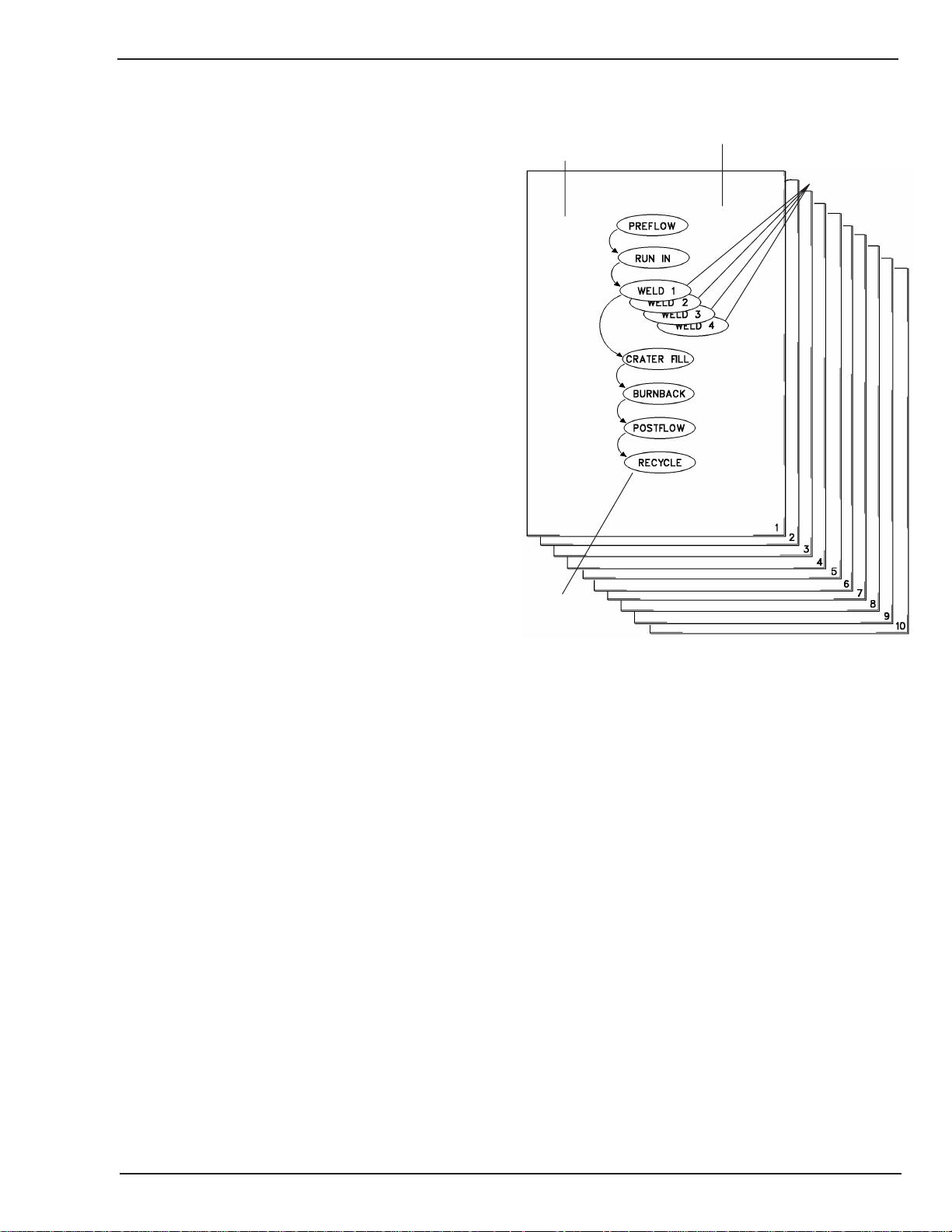
4.05 Programming
Programming for the HMC-410 is the process of setting
weld parameters into long term memory for each weld
schedule. Programming the HMC-410 is a simple task,
but as with everything new, may take some getting used
to.
SCHEDULE
HMC-410
ONE CYCLE = ONE TIME THROUGH
THE SEQUENCE
SUB SEGMENT
In understanding the programming of the HMC- 410, it
may be helpful to visualize the memory as a book with 10
pages. Each page contains the information for a complete
weld (see Figure 4-1). Each page contains the following
information:
Preflow Data — Time
Run In Data — Time, Voltage, Current
Weld Data — Time, Voltage, Current
Crater Fill Data — Time, Voltage, Current
Burnback Data — Time, Voltage
Postflow Data — Time
Recycle Data — Count, Sub Segment
On each page is taped four smaller pieces of paper, one
on top of another over the Weld Data. This is the weld
segment data. If the weld sub segment enable is enabled,
the bottom three pieces of paper can be viewed (one at a
time). Otherwise, just the top piece of paper can be viewed.
In order to view each page (schedule), the page to be
viewed is entered in the lower display when the SCHEDULE
light is illuminated. That entire page can then be viewed
by moving the MODE SELECT encoder. As that encoder
is rotated, each segment’s data becomes visible. In order
to change, instead of just viewing what is displayed, rotate
the encoder next to the value to be changed (remember
that to do this, the PROG/WELD key switch must be in
the PROG position).
Art # A-04368
SEGMENT
Cycle — one execution of a weld schedule
Schedule — collection of weld parameters describing
a weld procedure
Figure 4-1: Programming the HMC-410
In order to view any of the other smaller pieces of paper
in the weld data position, the smaller paper’s number is
entered into the RECYCLE segment’s WELD SUB
SEGMENT entry (1 to 4).
By performing this procedure on the full page (schedule),
the schedule is programmed with data pertinent to a
particular weld procedure. Once the data is entered, the
panel is ready to weld. In order to test the sequencing,
put the panel into test mode and initiate the weld as if it
were an actual weld. The timing should mimic the
programmed parameters, only without the power
source and feeder operating.
July 27, 2005
4-13
Page 56

HMC-410
Segment Programming
The details of programming each of the HMC- 410’s
segments are discussed in this section. Additionally, the
function of each segment is defined. The segments are
discussed in the order in which they would occur during
a weld cycle. The segments are selected by rotating the
MODE SELECT encoder. The segment selected is shown
by the light lit next to the segment.
Ready
The ready segment is not actually part of the weld
sequence. The top two displays of the ready segment
display the accumulated arc hours on the control panel.
The bottom display allows the operator to select the
schedule to be viewed, programmed, or executed.
Preflow
The preflow segment is programmed in time and is the
delay time before the start of run in and initiation of the
arc. The gas valve is turned on at the beginning of preflow
and remains on through the completion of postflow. The
time is programmed in the upper display. The range is 0
to 25.5 seconds, in .1 second increments.
Weld
The weld segment is responsible for the major portion of
the weld cycle. This segment has three programmable
parameters: time, voltage, and WFS. If the time is selected
to be continuous (CON in the upper display), the panel
requires the operator or master control to issue the stop
command to enter the crater fill segment. If the
programmed time is not continuous, the weld cycle is a
timed spot weld and will automatically proceed to the
crater fill segment after the weld time has expired.
The weld time is programmed in the upper display. The
time can be programmed from .1 to 25.5 seconds, in .1
second increments. When CON is displayed, the
continuous weld is selected. When OFF is displayed, that
weld sub segment is disabled. The various weld sub
segments are selected in the recycle segment.
The voltage is programmed in the center display. The
voltage can be programmed from the minimum
programmable voltage (0 to 10.0) to the maximum
programmable voltage (between 36.0 and 44.0), in .2 volt
increments.
SCHEDULE
ONE CYCLE = ONE TIME THROUGH
THE SEQUENCE
Run In
The run in segment has three programmable parameters;
the strike time or time allotted to strike the arc, voltage,
and WFS. Each of these signals is output at the beginning
of run in and remains constant until the next segment is
executed. If the arc is detected within the programmed
time, execution passes to the weld segment. If the arc is
not detected within the programmed time, the cycle will
be terminated and the control will return to the ready
segment and the ready mode.
The run in time is programmed in the upper display. The
time can be programmed from 0.2 to 25.5 seconds, in .1
second increments.
The voltage is programmed in the center display. The
voltage can be programmed from the minimum
programmable voltage (0 to 10.0) to the maximum
programmable voltage (between 36.0 and 44.0), in .2 volt
increments.
The WFS is programmed in the bottom display. The WFS
can be programmed from 0 to 8881 IPM (0 to 22.5 MPM),
in 4 IPM (.1 MPM) increments (888 is displayed, but the
actual limit is 887 IPM).
SUB SEGMENT
Art # A-04368
SEGMENT
Cycle — one execution of a weld schedule
Schedule — collection of weld parameters describing
a weld procedure
4-14
Figure 4-1: Programming the HMC-410
July 27, 2005
Page 57

HMC-410
Crater fill
Crater fill is normally used to reduce heat input to the
work and to fill the crater which is typically left at the
termination of the weld. Crater fill has three programmable
parameters: time, voltage, and WFS.
The crater fill time is programmed in the upper display.
The time can be programmed from 0 to 25.5 seconds, in
.1 second increments.
The voltage is programmed in the center display. The
voltage can be programmed from the minimum
programmable voltage (10.0) to the maximum
programmable voltage (between 36.0 and 44.0), in .2 volt
increments.
The WFS is programmed in the bottom display. The WFS
can be programmed from 0 to 888 IPM (0 to 22.5 MPM),
in 4 IPM (.1 MPM) increments.
Burnback
The burnback function is used to burn back the welding
wire from the work at the termination of the weld. This is
done by turning off the feed motor and leaving the power
source contactor on for a short period of time (typically
.2 second). The burnback segment is programmed in time
and voltage.
Recycle can also be used in a continuous weld as an ‘end
of weld’ segment. During the programmed Recycle time,
Auxiliary Relay 2 will close. At the conclusion of
Recycle,the panel will return to the Ready Mode,
regardless of the programmed recycle count.
The recycle time is programmed in the upper display. The
time can be programmed from 0 to 25.5 seconds, in .1
second increments.
The count is programmed in the center display. The count
can be programmed from 1 to 255.
Also included in the recycle segment is the weld sub segment
number (if enabled). This number is programmed in the
lower display. The number can be programmed from 1 to 4.
The burnback time is programmed in the upper display.
The time can be programmed from 0 to 2.55 seconds, in
.01 second increments.
The voltage is programmed in the center display. The
voltage can be programmed from the minimum
programmable voltage (10.0) to the maximum
programmable voltage (between 36.0 and 44.0), in .2 volt
increments.
Postflow
Programmed in time only, this is the duration of gas flow
at the completion of the weld. The postflow time is
programmed in the upper display. The time can be
programmed from 0 to 25.5 seconds, in .1 second
increments.
Recycle
Recycle is used with the spot weld mode for multiple
executions of a programmed weld cycle. Recycle is
programmed in the number of total cycles (i.e., 5 recycles
results in 5 spot welds), and the delay time between spot
welds. The delay time is the time between the end of the
postflow segment of the previous spot weld and the
beginning of the preflow segment of the next spot weld.
During this time the feed motor, gas valve, and power
source contactor are turned off.
July 27, 2005
4-15
Page 58

HMC-410
4.06 Setup
Before attempting to operate this system, read and
carefully follow instructions in the manuals for the HMC410, welding power source, and feedhead. Observe all
Safety Warning chapters included in all of these manuals.
Power Source Setup
The HMC-410 is designed to operate with the Arc-Master,
the Power Master, the Ultra Flex, the Fabstar 4030, the
Excel-Arc, and the RC/RCC Family of power sources. The
power source configuration will vary from machine to
machine so consult the manual for details. The following
sections will describe generally the power source setup
for the two families.
Arc-Master Inverter Family Configuration
Set “Remote/Local” toggle switch to REMOTE.
If CV welding, set process selection switch to GMAW/
FCAW.
If Pulsed MIG welding, set process selection switch to
PULSED GMAW. Also set “Pulsed MIG Schedule Select”
switch to the appropriate material and gas.
Fabstar 4030 Configuration
Set “Remote/Local” toggle switch to REMOTE.
Excel-Arc Family Configuration
Set the “Arc Voltage Control” toggle switch to
REMOTE.
Set the CC/CV Selector Switch to CV (if available).
Power Master
The amphenol connections/color codes are given here:
PinWire Color Function
A WHT-GRN Auxiliary Gas Purge
B WHT-RED Auxiliary Feeder Inch
C VIOLET
D GRAY
E GREEN Auxiliary Weld Sub
Segment Advance
F RED-BLK Auxiliary Start/Stop
G WHT-YEL
H RED Auxiliary Control (+30 VDC)
J WHT
K BLK
L WHT-BLK
M ORG Auxiliary Relay 2 Lo
N YEL Auxiliary Relay 2 Hi
P BLU Auxiliary Error Relay Lo
R BRN Auxiliary Error Relay Hi
S WHT-BLU Auxiliary Relay 1 Lo
T TAN Auxiliary Relay 1 Hi
HMC-410 Setup
The HMC-410 must be configured before it is powered
up for the first time. Refer to the System Configuration
section of this chapter for details.
Set Local/Remote to remote operation. Select GMAW
process.
Ultra Flex Configuration
Set Local/Remote to remote operation. Select process
(GMAW or Pulse GMAW).
Fixturing Setup
Any customer specific fixturing should be setup before
power is applied to the system. This fixturing should be
interfaced to the HMC-410 through the auxiliary interface
port. The functional description of this port is in the
Auxiliary description in the Description of Equipment
chapter of this manual.
4-16
After the HMC-410 is configured and installed following
the procedures set forth in this manual, attach all pertinent
cables to the HMC-410. Make sure that power is OFF on
the power source and HMC-410.
Power ON the power source and HMC-410. Program the
control panel. Instructions for this are given in the
Programming section of this chapter.
After the HMC-410 is configured, installed, programmed,
and properly connected with its associated equipment, it
is ready to use. The different modes of operation are
discussed in the following section of this manual.
July 27, 2005
Page 59

HMC-410
4.07 Operation
The HMC-410 may be used in an automatic or
semiautomatic welding configuration. Because of the
different requirements of these two types of welding
processes, the HMC-410 operates differently depending
on how it is used. The following sections will describe
how the control panel operates for automatic and
semiautomatic applications.
The operation discussion will pertain to starting and
stopping the weld, and if configured, executing weld sub
segments. The gas purge and wire feeder inch functions
can be operated on any interface regardless of the control
interface. For example, the front panel INCH button is
always active (if the control is in the ready mode) even if
the auxiliary interface or semiautomatic gun trigger
interface is used.
Automatic Operation
When in the automatic configuration, the HMC- 410 has
various methods of operation. If the unit is to be operated
from the front panel, the control panel would be
considered the master control (slave only to the operator),
and the rest of the equipment (particularly the fixturing)
would be slaved to control inputs from the panel. The
remote pendant operation is very similar to front panel
control, only certain controls of the front panel are
provided on a cable. Conversely, if the unit is to be
operated via the auxiliary interface, then the HMC- 410
becomes a slave to that interface, controlling only the
feeder, power source, and possibly timing. The following
sections will describe these different types of automatic
operation.
Front Panel Operation
When used in a front panel operation, the control panel
will require a weld operator to start and possibly stop the
weld. The proper weld schedule for the work should be
selected or programmed. Front panel controls GAS
PURGE and INCH can be used to test the gas and ready
the filler metal at the torch. Once the welding system and
the work is ready, the weld operator can start the weld by
pressing CYCLESTART on the front panel.
During welding, the front panel will display the segment
it is in and the amount of time in that segment. Also,
during run in, weld, and crater fill, actual arc voltage and
arc current/wire feed speed will be displayed (selectable
on the lower display with the MODE SELECT encoder). If
trim is enabled, the center encoder can be rotated to
increase/decrease arc voltage and the encoder cander can
be rotated to increase/decrease wire feed speed (and thus
current in a CV process).
Termination of the weld cycle will occur when either the
weld time expires (if the weld time is not CONtinuous, a
spot weld) or the weld operator presses CYCLE STOP. If
it is a spot weld, the control may automatically recycle to
another weld cycle if it were so programmed until the last
recycle is done or the CYCLE STOP is pressed. If the front
panel CYCLE START initiated the weld, only the front panel
CYCLE STOP will terminate the weld. This fact is
consistent for the remote pendant and the fixture.
After the weld terminates, the control panel returns to
the ready mode and is ready to start the sequence over
again.
Remote Pendant Operation
As already mentioned, remote pendant operation is similar
to front panel operation. The main point of difference is
that the operator has a pendant to allow him more mobility.
The front panel still provides the display information and
also the capability to trim.
Auxiliary Interface Operation
When the HMC-410 is controlled by the auxiliary interface, it acts as a slave to that interface. In this capacity,
the HMC-410 takes on the role of a power source control, feeder control, and possibly timing control in the
weld system. Because of this role change, the panel not
only needs to accept commands but send information
back to the auxiliary/ master.
The interfacing to the control panel acts similar to the
front panel type of control. The gas purge control will
cause the panel to close the gas valve, and the feeder
inch control will cause the panel to feed filler metal at the
rate programmed in the run in segment. The auxiliary
start/stop is different from the front panel start and stop
in that both functions are merged into one control. Start/
stop is run in the deadman mode; the control will continue
to weld as long as the control is in start. Once the control
line is not active, the control panel terminates the weld.
Also, the control panel must be in the stopped state before
it can start (for safety).
Also included in the auxiliary control interface is a weld
sub segment advance control, which when enabled (see
Soft Switch description) will cause the weld to change
parameters while in mid-weld. The segments to be
executed may be timed or continuous. If they are timed,
the sub segments will continue with the next sub segment
after time expires. If the sub segments are CONtinuous
timed, the sub segment can change by reissuing the weld
sub segment advance control. Once the sub segment
July 27, 2005
4-17
Page 60

HMC-410
executing tries to advance to a segment that is OFF or is
in the fourth sub segment, execution passes to the first
sub segment.
The auxiliary interface also provides three relay closure
signals to the fixturing. These relays provide information
on which phase of the weld cycle is active, as well as an
error output relay for fault notification. Relay 1 will close
during the weld segment of the weld. Relay 2 will close during
the recycle segment of the weld cycle. The error relay will
close during a tolerance or ground fault condition.
During weld cycle execution, the front panel will display
arc voltage, arc current and wire feed speed. Also, if
enabled, trim is active on the front panel.
For more information on the auxiliary interface, refer to
sections Fixturing Setup (located in this chapter) and
Auxiliary description located in the Description of
Equipment chapter.
Semiautomatic Operation
The HMC-410 has a wide variety of modes in which it can
operate when in a semiautomatic configuration. There are
four items which greatly impact how the control will react
to the gun trigger. They are:
Weld segment time — continuous/non-continuous
Weld sub segment enable — see soft switch
description
Manual Trigger Modes
Manual modes are selected with CONtinuous weld times.
Manual Single Segment Deadman Operation
Trigger pull and hold through weld, release advances to
crater fill.
Manual Multi Segment Deadman Operation
Pull and hold trigger through weld. Flicker the gun trigger
to advance to the next weld segment. Release for more
than one second to advance to crater fill.
Manual Single Segment Hold Operation
Pull and release the gun trigger before one second of the
weld segment has executed. If the gun trigger is still held
one second into the weld segment, the mode is considered
Manual Single Segment Deadman Operation. The next
time the gun trigger is pulled, the weld cycle continues
with crater fill.
Manual Multi Segment Hold Operation
Pull and release the gun trigger before one second of the
weld segment has executed. If the gun trigger is still held
one second into the weld segment, the mode is considered
Manual Multi Segment Deadman Operation. Flicker the
gun trigger to advance to the next weld segment. The
next time the gun trigger is pulled, the weld cycle
continues with crater fill.
Trigger hold enable — see soft switch description
Recycle count — if non-continuous weld segment time
When in the ready mode, the front panel INCH will feed
wire through the gun. The front panel GAS PURGE will
purge gas. Also, the INCH on the feeder package will feed
wire through the gun (if applicable).
When welding, the front panel displays arc voltage and
arc current/wire feed speed. Trim is active if enabled. Also,
at the completion of the weld the panel will continue to
display the last displayed values for arc voltage, arc
current, and wire feed speed. These will be displayed on
the lower and center displays in 1 second intervals for
the amount of time programmed in the recycle time. This
way the welder may view his welding parameters.
The following sections will describe how the control will
react to the gun trigger based on the control setup. The
‘hold’ modes are enabled by turning trigger hold on. The
‘multi segment’ operation is enabled by turning weld sub
segment on and programming the sub segments.
Spot/Stitch Trigger Modes
Spot modes are selected with Non Continuous weld times.
Stitch is selected with recycle count more than one.
Spot Deadman Operation —Recycle count is
programmed to one
Trigger pull and hold through the end of the weld segment,
release resets for the next spot weld. Releasing the trigger
before the end of the weld segment advances to crater
fill.
Stitch Deadman Operation
programmed to more than one
Trigger pull and hold through the end of the stitch, release
resets for the next stitch weld. Releasing the trigger before
the end of the stitch cycle advances to crater fill and ends
the current stitch cycle.
— Recycle count is
4-18
July 27, 2005
Page 61

HMC-410
Spot Hold Operation — Recycle count is
programmed to one
Trigger pull and release through the first second of the
weld segment (otherwise the mode defaults to the Spot
Deadman mode of operation). Pulling the trigger before
the end of the weld segment advances to crater fill.
Stitch Hold Operation — Recycle count is
programmed to more than one
Trigger pull and release through the first second of the
weld segment (otherwise the mode defaults to the Stitch
Deadman mode of operation). Pulling the trigger before
the end of the weld advances to crater fill and stops the
current stitch.
Operational Faults
During operation of the control panel, several factors can
create an operational fault. Faults for the HMC-410 are
grouped into three classifications:
Ground fault
Feeder fault, and
The tolerance fault will occur during welding. It will show
via a light on the front panel, the activation of the error
relay, and may terminate the weld cycle if the fault abort
function is enabled (See Soft Switch Description located
in the Operation chapter). This error is caused because
of arc voltage out of tolerance (± .5 Volt variance from
programmed value), wire feed speed out of tolerance (±
10 IPM variance from programmed value), or a loss of
arc established from the power source. The error will be
recognized if any of these conditions continuously persist
for more time than the fault delay time. This type of error
will clear itself once a new weld cycle is initiated.
NOTE
The error relay will close from the occurrence
of the error through .1 second after the weld
is done. It is envisioned that this relay will drive
a customer’s latching relay which can be reset
by the customer.
Tolerance fault
The ground fault is activated whenever a large current is
sensed through the earth ground from the power source
to the HMC-410 chassis. Since this is a significant safety
hazard, the control will immediately shut down all systems
under its control, excite the error light and relay, and
display “gnd Err” on the front panel. This will stay on
until the power is cycled on the control panel. This
situation should be researched and fixed before welding
is continued.
The feeder fault will be noticed by the fact that wire will
not feed during welding or during the INCH execution. If
there are no obvious impediments to the wire feeding
(e.g., blocked tip), then the feeder fault may have activated.
This occurs if the current through the motor exceeds
specifications. This could be from a bind on the feed, bad
cabling or
various other causes. In order to clear the error, power
should be cycled on the control panel. If the problem
persists, the feeder control cable, feeder, gun/torch, and
wire feed should be thoroughly checked for blockage and
short circuits.
July 27, 2005
4-19
Page 62

HMC-410
4-20
July 27, 2005
Page 63

HMC-410
SECTION 5:
SERVICE
5.01 Maintenance
The HMC-410 requires periodic maintenance to maximize
its life. The frequency of repairs given should be used as
a guideline, and in some situations may need to be
accelerated.
WARNING
Before attempting any maintenance, turn off
the controller and remove fuses of disconnect
switch supplying the power source with AC
line power.
5.02 Controller Maintenance
Every Day: check all cables, leads, and hoses for cuts or
other damage. Repair any damage immediately to prevent
shorts and further damage.
Once a Week: check the tightness of all electrical
connections. If arcing has occurred at any connection,
recondition the connection and securely refasten.
Every Six Months (more often if located in an excessively
dirty environment): use clean, dry, compressed air of not
over 25 PSI (172 kPa) to clean the control box internal
components.
WARNING
Interconnecting cables must be disconnected
before the execution of any diagnostic; the
controller interfaces will be active during the
diagnostic execution which could result in
uncontrolled activation of the power source,
fixture, and feedhead.
WARNING
Disconnecting the controller interconnecting
cables will expose the connector pins which
may contain lethal voltage levels (115 VAC).
The diagnostic procedures should be
attempted only by qualified service personnel.
CAUTION
Extreme care must be used when handling
the PC boards. Static discharge will damage
PC board components. A grounded wrist strap
should be used at all times when handling the
PC boards. Storage and shipment of PC boards
should be done in antistatic packaging.
WARNING
5.03 Troubleshooting
These troubleshooting instructions are given as an aid to
the user. In case of trouble, it is helpful to have a set of
instructions suggesting where to look. This may save
everyone involved time and resources if the problem can
be resolved on site. Certain problems may not be
resolvable on site, and it is also helpful to know this.
This section is divided into two areas: a troubleshooting
guide and the controller diagnostics. The troubleshooting
guide will state the problem and provide a list of items to
be checked. In isolating the problem, the controller
diagnostics may be of help. These diagnostics will give
the troubleshooter absolute control over the HMC-410
control panel’s interfaces.
May 5, 2005
Opening the HMC-410 control panel will
expose lethal voltage levels (115 VAC).
Disconnect all cables from the control panel
before servicing. Troubleshooting and service
should be done only by a qualified service
technician.
5-1
Page 64

HMC-410
5.04 Troubleshooting Guide
A. Controller will not power up
1. Power source is not turned on.
a. Turn on the power source.
2. Interconnecting cable between the power source
and controller is not plugged in or may have a bad
connection or short circuit.
a. Repair or replace the interconnecting cable.
3. Loose connections or faulty wiring in the controller
or power source.
a. Check power source and controller wiring for
loose or faulty connections.
4. Blown fuse in the controller or power source.
a. Check power source fuses. Check controller
fuses (refer to Power Source/Motor Control
PCB Assembly description located in the
Description of Equipment chapter).
5. Controller’s power switch is bad.
a. Replace power switch.
B. No voltage control on the power source, but
programming appears to be correct.
1. Power source front panel settings may be
incorrect.
a. Check power source front settings with respect
to the desired setup.
2. Interconnecting cable between the power source
and controller may have a bad connection or short
circuit.
a. Repair or replace the interconnecting cable.
3. Power source fault.
C. No power source output.
1. Cycle test mode is active.
a. Turn off cycle test.
2. Interconnecting cable between the panel and power
source may have a bad connection or short circuit.
a. Repair or replace interconnecting cable.
3. Controller problem.
a. Check power source contactor relay (diagnostic
test #49).
b. Replace controller board or relay if bad.
4. Power source problem.
a. Check power source manual for service
information.
5. Blown fuse in the controller or power source.
a. Check PS/MC board’s fuses (easily done by
checking power LEDs). Also check in power
source. Replace if bad fuse is found.
D. Power source is always energized.
1. Interconnecting cable between the controller and
the power source has a short circuit (pins A, B).
a. Repair or replace cable.
2. Controller problem.
a. Check PS contactor drive circuit and relay in
the controller using the controller diagnostic
test #49. Replace relay or controller board if
bad.
3. Power source problem.
a. Check power source manual for service
information.
a. Check power source manual for service
information.
4. Blown fuse/power regulator in the controller.
a.Verify ±15 VDC on PS/MC board. Replace fuses
if blown. Replace board if fuses are good.
5. Controller fault.
a. Check for loose or faulty connections. Check
Power Source Control Output diagnostic output
(diagnostic test #1).
b. Replace controller board if a bad channel is
detected.
5-2
July 27, 2005
Page 65

HMC-410
E. No wire feed speed control, but programming
appears to be correct.
1. Tachometer failure. The normal symptom of tach
failure is that the feed motor runs at full speed
whenever the motor is activated.
a. Adjust or replace PC board in motor housing.
2. Interconnecting cable between the controller and
feedhead is not plugged in or may have a bad
connection or short circuit.
a. Repair or replace interconnecting cable.
3. PS/MC PC board failure.
a. Replace motor control PC board or bad drive
component.
4. Controller board failure.
a. Check wire feed speed control signal on con-
troller board using diagnostic test #2. Replace
controller board if
defective.
F. Wire feed motor does not run, but programming
appears to be correct.
1. Cycle test mode is active.
a. Turn off cycle test mode.
2. Interconnecting cable between the controller and
feedhead is not plugged in or may have a bad
connection or short circuit.
a. Repair or replace interconnecting cable.
3. PS/MC board failure.
a. Replace motor control board or bad drive
component.
4. Controller board failure.
a. Check wire feed speed control signal on
controller board using diagnostic test #2.
Replace controller board if defective.
5. Blown fuse on the PS/MC board.
a. Replace fuse.
5. Blown fuse on the PS/MC board.
a. Replace fuse.
6. Over current shutdown on PS/MC board.
a. Replace fuse.
6. Over current shutdown on PS/MC board.
a. This could be from a bind on the feed, bad
cabling or various other causes. In order to
clear the error, power should be cycled on the
control panel. If the problem persists, the
feeder control cable, feeder, gun/torch, and wire
feed should be thoroughly checked for
blockage and short circuits in the feeder control
cable. EMI can also create this problem, so
check for electrical interference in the area (like
TIG machines).
7. Motor failure.
a. Verify motor/feeder is not frozen or stuck.
Replace motor.
G. Wire feed motor will not inch, but motor will run
during the weld cycle.
1. C/D board failure.
a. Replace C/D board.
2. Controller board failure.
May 5, 2005
a. Replace Controller Board.
3. C/D board/Controller board ribbon cable
interface failure.
a. Repair or replace ribbon cable.
5-3
Page 66

HMC-410
H. Gas valve is stuck on or off.
1. Interconnecting cable between control panel and
feedhead may have a bad connection or short
circuit.
a. Repair or replace interconnecting cable.
2. Gas valve control relay failure on controller board.
a. Check relay control signal using diagnostic test
#50. Replace relay or controller board if bad.
3. Gas valve failure.
a. Replace valve.
4. 24 VAC failure.
a. Check 24 VAC out of transformer by checking
+15 VDC UNREG LED on PS/MC board.
Replace transformer if bad.
I. Front panel does not function.
1. Unit does not power up
a. Verify unit powers up. Verify PS/MC board
voltages are OK by checking the power LEDs.
3. Incorrectly installed cable, switches.
a. Verify cables installed on controller board
correctly. Verify option switches are in the
correct position.
K. Schedule program data lost or corrupted after
controller power down. Also, if OFF is displayed
for Schedule Number.
1. Bad memory chip.
a. Replace controller board.
L. Control panel fails to respond to control input or
responds unusually.
1. Line voltage drop or spikes on the AC power line.
a. Isolate controller AC power lines.
2. EMI radiation from equipment in the vicinity of
the controller.
a. Remove suspect equipment from the vicinity.
Reduce interconnecting cable lengths to a
minimum. Be sure all weld system equipment
is properly grounded to earth ground.
2. Interconnect between C/D board and controller
board. Interconnect between controller board and
PS/MC board.
a. Verify cables are good. Repair or replace if de-
fective.
3. Defective controller board.
a. Replace controller board if bad. One easy way
to check if the controller board is working
without seeing the front panel is to select
diagnostics test #49 and #48 alternatively. If
the relay can be heard turning on and off (it is
very quiet but audible), the board can be
presumed to be functioning. Replace if not
functioning.
4. Defective C/D board.
a. Replace C/D board.
J. DIP switch functions do not work.
1. Bad DIP switch.
a. Replace controller board.
2. Controller board failure.
3. Controller board failure.
a. Replace controller board.
4. Unusual weld starts or transients from the power
source.
a. Check power source for malfunctions.
M. The controller allows the weld cycle to progress
through the run in segment and terminates the
cycle.
1. Power source is not providing an arc established
signal.
a. Check power source manual for service
information.
2. Controller does not recognize the arc established
signal provided by the power source, may be a
bad controller board channel or interconnect to I/
S board.
a. Replace controller board, I/S board, or
controller to I/S ribbon cable.
3. Difficulty starting arc due to dirty work or improper
programming.
a. Replace controller board.
5-4
a. Reprogram run in parameters, lengthen time,
increase arc voltage and/or wire feed speed.
July 27, 2005
Page 67

N. Auxiliary relays do not function.
1. Interconnecting cable between control panel and
fixture may have a bad connection or short circuit.
a. Repair or replace interconnecting cable.
2. Fixture control relays failure on controller board.
Interconnect between I/S board and controller
board. Interface/Suppressor board failure.
a. Check relay control signal using diagnostic test
#51 and #52. Replace bad component. If these
go bad, also verify that fixture load is not more
than 115 VAC, 2 A, and that proper load
suppression techniques were employed.
HMC-410
May 5, 2005
5-5
Page 68

HMC-410
5.05 Diagnostics
Each test described in this section is selected in one of
two ways: (1) with the DIP switch on the controller board
or (2) with the Diagnostics Select soft switch (described
in the System Configuration section located in Operation
chapter). Selecting with the Diagnostics Select soft switch
is the preferred method because it does not require access
to the inside of the panel.
In order to select the Diagnostic Test with the DIP
switches, consult the Built in Test Definition table (on
following page). The position of the DIP switch for the
selected test is shown to the right of the test, with a 1
being OPEN (switch pressed on the OPEN side), and a 0
is closed. The toggle switches on the front panel are tied
into this DIP switch, so they will need to be set to the UP
position. Note that DIP switch 9 is not required and can
be kept in the OPEN position.
IMPORTANT: Note that by selecting a diagnostic with
the DIP switches, the configuration of the control unit
is changed. It is important to record the position of the
DIP switches before a test is selected so that the unit
can be reconfigured to its pre-test setup (typically all
OPEN).
DISP B is the center display. All tests will display the test
number in the upper display. If diagnostics are enabled,
but the combination of switches is not one of the shown
tests, the controller board will perform test number 60,
EEPROM Test, which will reset the panel’s configuration
to its default settings.
5-6
July 27, 2005
Page 69

5.06 Built In Test (BIT) Definition
Switch Position
1=OPEN, 0=CLOSED
Test No. Name Description SSSSSSSS
12345678
1 POWER SOURCE The Power Source Control Voltage will output a 01000000
VOLTAGE 5 VDC 5 VDC signal onto J3-6.
2 WIRE FEEDER The wire feed speed control voltage output 00100000
VOLTAGE 8 VDC will output a 8.0 VDC voltage on pin J1-13.
3 DISPLAY CH0 The conversion of the Arc Voltage input 01100000
(ARC VOLTAGE) voltage is output to the display board’s DISP B.
4 DISPLAY CH1 The conversion of the Arc Current input 00010000
(ARC CURRENT) voltage is output to the display board’s DISP B.
5 DISPLAY CH2 The conversion of the WFS Tach Reference 01010000
(WFS TACH REF) input voltage is output to the display board’s
DISP B.
6 DISPLAY CH3 The conversion of the inverter arc current 00110000
(INVERTER ARC input voltage is output to the display board’s
CURRENT) DISP B.
7 DISPLAY CH4 01110000
8 DISPLAY CH5 The conversion of the Power Source 00001000
(PS SIGNATURE) Signature’s input voltage is output to the
display board’s DISP B.
9 DISPLAY ALL LEDS The display board is directed to display all 8’s 01001000
(AND 8’S) on the seven segment displays.
10 DISPLAY LED1 The display board turns on LED1 (craterfill). 00101000
11 DISPLAY LED2 LED2 (burnback) is turned ON. 01101000
12 DISPLAY LED3 LED3 (postflow) is turned ON. 00011000
13 DISPLAY LED4 LED4 (recycle) is turned ON. 01011000
14 DISPLAY LED5 LED5 (ready) is turned ON. 00111000
15 DISPLAY LED6 LED6 (preflow) is turned ON. 01111000
16 DISPLAY LED7 LED7 (run in) is turned ON. 00000100
17 DISPLAY LED8 LED8 (weld) is turned ON. 01000100
18 DISPLAY LED9 LED9 (wfs) is turned ON. 00100100
19 DISPLAY LED10 LED10 (schedule) is turned ON. 01100100
20 DISPLAY LED11 LED11 (test) is turned ON. 00010100
21 DISPLAY LED12 LED12 (error) is turned ON. 01010100
22 DISPLAY LED13 LED13 (time) is turned ON. 00110100
23 DISPLAY LED14 LED14 (arc hours) is turned ON. 01110100
24 DISPLAY LED15 LED15 (volts) is turned ON. 00001100
25 DISPLAY LED16 LED16 (count) is turned ON. 01001100
HMC-410
May 5, 2005
Table 5-1a: Built In Test Definitions
5-7
Page 70

HMC-410
5.06 Built In Test (BIT) Definition (continued as Table 5-1b)
Switch Position
1=OPEN, 0=CLOSED
Test No. Name Description SSSSSSSS
12345678
26 DISPLAY LED17 LED17 (amps) is turned ON. 00101100
27 DISPLAY LED18 LED18 (arc hours x100) is turned ON. 01101100
28 DISPLAY LED19 LED19 (prog delay) is turned ON. 00011100
29 DISPLAY LED20 LED20 (weld segment) is turned ON. 01011100
30 DISPLAY LED21 LED21 (c4a) is turned ON. 00111100
31 DISPLAY SE1 Current shaft position (0 to 255) is output to 01111100
DISP B. Turning SE1 CW will increase this
number, and CCW will decrease this number.
32 DISPLAY SE2 Current shaft position (0 to 255) of SE2 is 00000010
output to DISP B. Turning SE2 CW will
increase this number, and CCW will decrease
this number.
33 DISPLAY SE3 Current shaft position (0 to 255) of SE3 is 01000010
output to DISP B. Turning SE3 CW will
increase this number, and CCW will decrease
this number.
34 DISPLAY CH5 The conversion of the Power Source 00001000
(PS SIGNATURE) Signature’s input voltage is output to the
display board’s DISP B.
35 Display Start Display B will display the state of the Front 01100010
Panel Start Switch. 0 = Pressed,
1 = Not Pressed
36 Display Cycle Test Display B will display the state of the Cycle 00010010
Test Switch. 0 = Pressed, 1 = Not Pressed
37 Display Inch Display B will display the state of the lnch 01010010
Switch. 0 = Pressed, 1 = Not Pressed
38 Display Purge Display B will display the state of the Purge 00110010
Switches. 0 = Pressed, 1 = Not Pressed
39 Display Program/Weld Display B will display the state of the 01110010
Program/Weld Switch. 0 = Pressed,
1 = Not Pressed
40 Display Stop Display B will display the state of the Front 00001010
Panel Stop Switch. 0 = Pressed,
1 = Not Pressed
41 Display Gun Trigger Display B will display the state of the Gun 01001010
Trigger. 0 = Pulled, 1 = Not Pulled
42 Display Aux Seg Display B will display the state of the Auxillary 00101010
Advance Segement Advance. 0 = Pressed,
1 = Not Pressed
43 Display Remote Start Display B will display the state of the Remote 01101010
Start Switch. 0 = Pressed, 1 = Not Pressed
5-8
July 27, 2005
Page 71

HMC-410
5.06 Built In Test (BIT) Definition (continued as Table 5-1c)
Switch Position
1=OPEN, 0=CLOSED
Test No. Name Description SSSSSSSS
12345678
44 Display Remote Stop Display B will display the state of the Remote 00011010
Stop Switch. 0 = Pressed, 1 = Not Pressed
45 Display Aux Start/Stop Display B will display the state of the 01011010
Auxiliary Start/Stop Switch. 0 = Pressed, 1 =
Not Pressed
46 Display Arc Established Display B will display the state of Arc 00111010
Established. 1 = Arc Established,
0 = Arc Not Established
47 Display Ground Fault Display B will display the state of the Ground 01111010
Fault. 0 = Ground Fault, 1 = No Ground Fault
48 Display Ground Fault Display B will display the state of the Ground 00000110
(Latched) Fault Latch. 0 = Ground Fault has occurred,
1 = No Ground Fault has occurred.
49 RELAY 0 TEST Contactor Relay Closed. 01000110
50 RELAY 1 TEST Gas Valve Relay Closed. P1-7 will have 24 00100110
VAC Hi on it.
51 RELAY 2 TEST Fixture Relay #1 Closed. 01100110
52 RELAY 3 TEST Fixture Relay #2 Closed. 00010110
53 RELAY 4 TEST Error Relay Closed. 01010110
54 RELAY 5 TEST 00110110
55 RELAY 6 TEST 01110110
56 IL2 TEST 00001110
57 RAM TEST The RAM test will perform a diagnostic test 01001110
on internal RAM. The top display will display a
memory location (selected by the top encoder)
and the middle display will display a value
written to RAM (selected by the middle
encoder). The bottom display will show the
data at that memory location; if the RAM is
working correctly, that value will be the same
as the number in the middle display.
58 No Test
59 EEPROM This selection will configure the schedules 01101110
60 Initialization and softswitches to factory defaults. This 00011110
selection will show the test number in the top
display, and count numbers in the middle
display (normally 1 to 255, with some jumping
around towards the end). When the middle
display clears, the initialization is complete.
May 5, 2005
5-9
Page 72

HMC-410
5-10
July 27, 2005
Page 73

SECTION 6:
ACCESSORIES AND OPTION
DESCRIPTIONS
6.01 Remote Pendant Description
The remote pendant is an option for remote control
operation of the control panel. Features under remote
control include Cycle Start, Cycle Stop, Wire Feed
(Inch), and Gas Purge. If the remote pendant is not to
be used, this section can be skipped. The Remote
Pendant is shown in Figure 6-1.
CYCLE START BUTTON - This button is used for remote
pendant initiation of the weld cycle. When pressed, the
control will initiate the selected weld schedule. Pressing
this button while in a weld has no effect.
CYCLE STOP BUTTON - This button is used for termination
of the remote pendant initiated weld cycle. When pressed,
the control will proceed to the crater fill segment of the
weld cycle. Also, recycle will be disabled so that the weld
will stop after the postflow segment. Pressing this button
during a gun switch, front panel, or fixture initiated weld,
or during standby, will have no effect.
HMC-410
Art # A-04369
Gas PURGE BUTTON - This button will turn on the gas
valve when pressed. This button has no effect during a
weld.
INCH BUTTON - This button will feed wire (at the rate
programmed in the Run In WFS setting) when pressed.
This button has no effect during a weld.
6.02 Feedhead
170896A-002 60 - 888 IPM
6.03 Feed Roll Kits
375980-XXX (one kit is supplied standard, but part
number must be specified at time of order).
Figure 6-1: Remote Pendant
July 27, 2005
6-1
Page 74

HMC-410
6.04 Control Cables:
These control cables are used from the HMC-410 to the
power source, and for the HMC-410 to the feedhead, thus
2 are required per system.
Description Part Number
2’ Control Cable 170552-005
10’ Control Cable 170552-001
15’ Control Cable 170552-006
25’ Control Cable 170552-002
50’ Control Cable 170552-003
75’ Control Cable 170552-007
100’ Control Cable 170552-004
6.05 171238-17 Software Kits
The 171238-17 Software Kit has the following additional features:
Feature Benefit
1. Programmable Gun Switch A. Allows user to customize gun switch speed for changing weld levels
Sensitivity (SP) at gun with a flick of the switch.
2. Password Protection (UPS, A. Allows the supervisor to protect weld settings.
SPS) B. Eliminate uncontrolled access to importanct weld parameters.
3. Arc Monitoring (IL, IP) A. Allows customer to perform some basic weld monitoring.
B. Verify that basic weld currents occur for some set amount of time.
4. Trim Adjustment Range A. Allows customer to limit amount of change by operators from some
(ADJ) preset level
B. Allows operator ability to tweak in operating point while reducing the
possibility of operating out of the process range
5. Remote Schedule Selection A. Ability to select 1 of 8 schedules remotely while welding or in standby
(RSE)
6. Display Filter (DF) A. Ability to make display read update at an optimum rate for each
application
Table 6-1: Software Kits 171238-17
See the descriptions of the softswitches for details on these and other additions to the HMC-410 capability.
6-2
July 27, 2005
Page 75

HMC-410
6.06 171238-19 Software Kits
The 171238-19 Software Kit has the following additional features (beyond all of the features described in the 17123817 described above):
Feature Benefit
1. Gun Switch Selectable Schedule A. Ability to change welding schedule by flickering gun switch in standby.
(RSE: Gun) B. Useful for situations where welder may be away from welder, but still
wishes to change to an alternate welding schedule
2. Limited Segment Adjustment A. Limit ability to change parameters to just ‘weld’ segment
(AS) B. Avoid confusion to operators by allowing them to change only main
weld parameters.
Table 6-2 Software Kits 171238-19
See Softswitch Descriptions for details on these and other additions to the HMC-410 capability.
6.07 171238 Software Kits
A variety of software kits have been released for the HMC-
410. As new customer requests / requirements are
generated, these additional features are normally
implemented as a new dash number of kit. The following
table shows the softswitch screens, and which softswitch
screen is implemented with which kit number. The
softswitch description details the additional features
available with each kit. The standard HMC-410 is delivered
with the ‘-3’ software, and upgrades are available through
your normal channels.
July 27, 2005
6-3
Page 76

HMC-410
6.08 870236 Robotic Interface Kits
870236-001 ABB Robotic Interface Kit
This kit includes the components required to allow the HMC-410 to plug into the 24 position amphenol connector
provided on the ABB robots.
Feature Benefit
1. 24 Position Amphenol A. Easy to install welding interface for Thermal Arc welder to ABB Robot
2. Analog Voltage Control A. Control welding voltage (or pulse frequency) remotely from robot
controller.
B. Integrate robot control of welding voltage for none, some, or all of the
welding segments for maximum flexibility.
3. Analog Wire Feed Speed Control A. Control wire feed speed remotely from robot controller.
B. Integrate robot control of wire feed speed for cold inching or welding
for none, some, or all of the welding segments for maximum flexibility.
4. Robot Controlled Gas A. Allows robot control of shielding gas
5. Robot Controlled Wire Forward A. Allows robot control of wire in the forward direction
6. Robot Controlled Wire Reverse A. Allows robot control of wire in the reverse direction
7. Robot Controlled Contactor A. Allows robot control of the welder output terminals
8. Welder Ready Signal A. Communicates status of welder to robot
9. Welder Inhibit Signal A. Communicates selection of a test (cold run) mode to the robot
10. Weave Inhibit Signal A. Communicates selection of a weave inhibit mode to the robot
11. Inch Speed Signal A. Communicates selection of a local inch command to the robot
12 Arc Established Signal A. Communicates selection of an Arc Established condition to the robot
13. Wire Stuck Signal A. Communicates the occurrence of a wire stuck to the work condition
to the robot
14. Water/Gas Sensor Signal A. Communicates the occurrence of a lack of water or shielding gas
condition to the robot
Table 6-3: Robotic Interface Kits
Included in this kit are:
(1) One 870200 Robotic Interface Board
(2) One 870213 24 Position Amphenol Board
(3) One 870210 12 VDC Wire Stick Sensing Board
(4) One 6 Position Terminal Strip for Water/Gas/Wire Sensors
(5) Cables and Other Installation Hardware for this Kit
(6) Installation and Operating Instructions
6-4
July 27, 2005
Page 77

HMC-410
6.09 870236-002 Fanuc Robotic Interface Kit
This kit includes the components required to allow the HMC-410 to plug into the 37 position amphenol connector
provided on the Fanuc robots.
Feature Benefit
1. 37 Position Amphenol A. Easy to install welding interface for Thermal Arc welder to Fanuc Robot
2. Analog Voltage Control A. Control welding voltage (or pulse frequency) remotely from robot
controller.
B. Integrate robot control of welding voltage for none, some, or all of the
welding segments for maximum flexibility.
3. Analog Wire Feed Speed
Control
4. Analog Arc Current Signal A. Communicates actual arc current to the robot
5. Analog Arc Voltage Signal A. Communicates actual arc voltage to the robot
6. Robot Controlled Gas A. Allows robot control of shielding gas
7. Robot Controlled Wire Forward A. Allows robot control of wire in the forward direction
8. Robot Controlled Wire Reverse A. Allows robot control of wire in the reverse direction
9. Robot Controlled Master Weld A. Allows robot control of the welding sequence by commanding a start
Control or end of the weld
10. Welder Fail Signal A. Communicates status of welder to robot
11. Arc Established Signal A. Communicates selection of an Arc Established condition to the robot
12. Wire Stuck Signal A. Communicates the occurrence of a wire stuck to the work condition
13. Water Sensor Signal A Communicates the occurrence of a lack of water condition to the robot
14. Gas Sensor Signal A. Communicates the occurrence of a lack of shielding gas condition to
15. Wire Sensor Signal A. Communicates the occurrence of a lack of welding wire condition to
A. Control wire feed speed remotely from robot controller.
B. Integrate robot control of wire feed speed for cold inching or welding
for none, some, or all of the welding segments for maximum flexibility.
to the robot
the robot
the robot
Table 6-4: Fanuc Robot Kits
Included in this kit are:
(1) One 870200 Robotic Interface Board
(2) One 870244 37 Position Amphenol Board
(3) One 870210 12 VDC Wire Stick Sensing Board
(4) One 6 Position Terminal Strip for Water/Gas/Wire Sensors
(5) Cables and Other Installation Hardware for this Kit
(6) Installation and Operating Instructions
July 27, 2005
6-5
Page 78

HMC-410
6.10 870236-003 Comau Robotic Interface Kit
This kit includes the components required to allow the HMC-410 to plug into the 64 position amphenol connector
provided on the Comau robots.
Feature Benefit
1. Analog Voltage Control A. Control welding voltage (or pulse frequency) remotely from robot
controller.
B. Integrate robot control of welding voltage for none, some, or all of the
welding segments for maximum flexibility.
2. Analog Wire Feed Speed
Control
3. Robot Controlled Gas A. Allows robot control of shielding gas
4. Robot Controlled Wire Forward A. Allows robot control of wire in the forward direction
5. Robot Controlled Contactor A. Allows robot control of the welder output terminals
6. Arc Established Signal A. Communicates selection of an Arc Established condition to the robot
7. Wire Stuck Signal A. Communicates the occurrence of a wire stuck to the work condition
A. Control wire feed speed remotely from robot controller.
B. Integrate robot control of wire feed speed for cold inching or welding
for none, some, or all of the welding segments for maximum flexibility.
to the robot
Table 6-5: Comau Robot Kits
Included in this kit are:
(1) One 870200 Robotic Interface Board
(2) One 870244 37 Position Amphenol Board
(3) One 870210 12 VDC Wire Stick Sensing Board
(4) One 6 Position Terminal Strip for Water/Gas/Wire Sensors
(5) Cables and Other Installation Hardware for this Kit
(6) Installation and Operating Instructions
6-6
July 27, 2005
Page 79

6.11 Other Available Options
1. Wire Spool Kit 870058
2. Wire Reel Kit 870059
3. Wire Reel / Spool Support Assembly 870060-001
4. Base Plate (For Mounting Feedhead, Wire Reel / Spool Support) 375769-004
5. Base Plate (For Mounting 410 Onto Power Supply) 170962
6. * 60 Lb. Coil Adapter 407142A
7. * 30 Lb. Spool Cover 375582A-004
8. * 60 Lb Spool Cover / Lifting Eye 375733A-001
9. ** Lifting Eye Kit 375104A
10. Semiautomatic Trigger Hold / Subsegment Controls 170925-001
11. Remote Pendant With 15’ Cable (Start, Stop, Inch, Purge) 170470A-002
12. 10’ Remote Pendant Extension Cable 170486-001
13. 35’ Remote Pendant Extension Cable 170486-002
14. 10’ Auxiliary Control Cable 170487-001
15. 25’ Auxiliary Control Cable 170487-002
16. Random Schedule Select Cable 171239-001
17. Dual Feeder Interlock Box 870008-001
18. Inch/Purge Switch For Dual Feeder Interlock Box Only 870023
19. Software Upgrades (Consult Factory) 171238-XXX
20. ¾" Gun Adapter 375999
HMC-410
Table 6-6: Additional Options
* Must Be Used With Both 870058 & 870060-001
** Must Be Used With 870060-001 Only
July 27, 2005
6-7
Page 80

HMC-410
6-8
July 27, 2005
Page 81

HMC-410
SECTION 7:
GLOSSARY
Arc Established — A signal generated by the power
source indicating that an arc is struck from the wire to
the work.
Arc Hours — Amount of time that the control panel has
been in control of an arc, i.e., the accumulated amount of
weld time on the panel.
Automatic Configuration — This is the configuration
where the weld is controlled entirely by the welding
equipment.
CV — constant voltage power source.
Deadman Operation — This mode of operation requires
that the control signal to start an event is required
throughout the whole event or that event will be
terminated.
Fault — A condition where an operation normally under
control of the panel is not operating correctly. Faults can
be Ground, Feeder, or Tolerance Faults. See Operational
Faults section located in the Operation chapter.
Fault Abort — The control panel will terminate the weld
by proceeding to the crater fill segment when a tolerance
fault is recognized by the control panel (see Fault Delay
Time) and the fault abort is enabled. See Soft Switch
section located in the Operation chapter.
Fault Delay Time — The amount of time that a tolerance
fault condition must continuously exist before the control
panel recognizes the error. This time is default set to 1
second, or programmable. See Soft Switch section located
in the Operation chapter.
Maximum Programmable Voltage — This voltage is the
maximum number that can be programmed in the center
display for the run-in, weld, crater fill, and burnback
segments. This number changes depending on the type
of power source that is used.
The following table shows the various maximums:
RC/RCC 300 36 V
RC/RCC 450 42 V
RC/RCC 650 44 V
Arc-Master 501 40 V (44 V Pulsed MIG)
Arc-Master 351 38 V (44 V Pulsed MIG)
Fabstar 4030 36 V
Excel-Arc 4030 36 V
Excel-Arc 6045 42 V
Excel-Arc 8065 44 V
Ultra Flex CC/CV 38 V (44 V Pulsed MIG)
Ultra Flex Pulse 38 V (44 V Pulsed MIG)
Minimum Programmable Voltage — This voltage is the
minimum number that can be programmed in the center
display for the run-in, weld, crater fill, and burnback
segments. This number changes depending on the type
of power source that is used. The following table shows
the various minimums:
RC/RCC 300 10 V
RC/RCC 450 10 V
RC/RCC 650 10 V
Arc-Master 500 10 V (0 V Pulsed MIG)
Feeder Fault — This occurs if the current through the
motor exceeds specifications. This could be from a bind
on the feed, bad cabling or various other causes. This
fault will disable the motor control circuitry. In order to
clear the error, power should be cycled on the control
panel.
Ground Fault — The ground fault occurs when a large
current is sensed through the earth ground from the
power source to the HMC-410 chassis. This fault will
cause the control panel to shut down all systems under
its control since it is a significant safety hazard.
July 27, 2005
Arc-Master 350 10 V (0 V Pulsed MIG)
Fabstar 4030 10 V
Excel-Arc 4030 11 V
Excel-Arc 6045 12 V
Excel-Arc 8065 14 V
Ultra Flex CC/CV 10 V (0 V Pulsed MIG)
Ultra Flex Pulse 10 V (0 V Pulsed MIG)
7-1
Page 82

HMC-410
Multi Sub Segment Operation — This type of operation
allows the weld parameters to automatically change during
a weld without stopping and restarting the weld. Refer to
the Operation chapter for more details.
Nonvolatile Memory — This memory will store the
various, long term programmable parameters. Nonvolatile
means that it is not disrupted by power loss.
Ready Mode — The mode in which the control panel
segments can be viewed, and if so privileged,
programmed. The control panel is in ready mode if the
unit is not in a weld cycle, and is not performing
diagnostics.
Schedule — The collection of various segments which
together describe a complete weld.
Semiautomatic Configuration — This configuration is
where the control panel controls the power source and
the feeder, but the welder moves, guides, and directs the
arc on the work. In this configuration, the HMC-410 may
typically be physically placed on a feeder.
Sequence/Weld Sequence — Weld cycle.
Trim — This capability allows the weld operator to change
the weld parameters arc voltage and WFS during the weld.
See Soft Switch section located in the Operation chapter.
Weld Cycle — A weld cycle is the completion of the
segments preflow through postflow once. Thus, if a
schedule dictates a recycle, this would be considered
multiple weld cycles.
Weld Segment — The weld segment is the segment
which describes the static part of the weld. This segment
will dictate if the weld is a spot weld (time noncontinuous), or a continuous weld.
WFS — wire feed speed.
Soft Switch — Soft switches allow for setup of
configuration parameters. Refer to the Operation chapter
for more details.
Sub Segment — The weld sub segment(s) are segments
which can be executed while the weld is in the weld
segment. This may be required because of discontinuity
in the work where different weld parameters are required.
See Operation chapter for a description of the weld sub
segment operation.
Tolerance Fault — This error is caused because of arc
voltage out of tolerance (± .5 Volt variance from
programmed value), wire feed speed out of tolerance (±
10 IPM variance from programmed value), or a loss of
arc established from the power source. If any of these
conditions continuously persist for more time than the
fault delay time the error will be recognized. If the fault
was caused by the loss of arc established, the panel will
shut off the power source and feeder automatically. This
type of error will clear itself once a new weld cycle is
initiated.
Trigger Hold — For semiautomatic applications. The
trigger hold feature allows the welder to initiate the weld
with a momentary pull of the switch, and terminate the
weld with another momentary pull of the switch. The full
description of this process is described in the
Semiautomatic section located in the Operation chapter
of this manual.
7-2
July 27, 2005
Page 83

SECTION 8:
PARTS LIST
8.01 Equipment Identification
All identification numbers as described in the Introduction
chapter must be furnished when ordering parts or making
inquiries. This information is usually found on the
nameplate attached to the equipment. Be sure to include
any dash numbers following the Specification or Assembly
numbers.
8.02 How To Use This Parts List
The Parts List is a combination of an illustration (Figure
Number) and a corresponding list of parts which contains
a breakdown of the equipment into assemblies,
subassemblies, and detail parts. All parts of the equipment
are listed except for commercially available hardware, bulk
items such as wire, cable, sleeving, tubing, etc., and
permanently attached items which are soldered, riveted,
or welded to another part. The part descriptions may be
indented to show part relationships.
HMC-410
To determine the part number, description, quantity, or
application of an item, simply locate the item in question
from the illustration and refer to that item number in the
corresponding Parts List.
An “Application Code” is used to distinguish parts that
are applicable only to certain Specifications and/or
Assemblies. This code is found in the right most column
of the Parts List. If an item in the Parts List applies to all
Specifications or Assemblies, the word “ALL” will be in
the Application Code column. Refer to the following list to
determine the appropriate Application Codes for the
Specifications or Assemblies covered by this manual. If
only the assembly or specification number is listed, the
use of an Application Code does not apply to this manual.
SPEC NUMBER APPLICATION CODE
100050-1 A
100050-2 B
July 27, 2005
8-1
Page 84

HMC-410
8.03 Parts List for the Control Box Assembly (1 of 2)
ItemItem
Item
ItemItem
NumberNumber
Number
NumberNumber
1 170913A-1 Bracket - Mounting 2 All
2 870071 Cover - Control Box 1 A
3 204036 Label - Warning 1 All
4 870239 Wrapper - Control Box 1 All
5 870087-1 Label - Company 2 All
6 170860B-1 Board - P.C. Microprocessor - See Note 2 1 A
7 375426-4 Spacer - P.C. Board 6 All
8 870284 Board - PC, Control & Display 1 A
9 375426-1 Spacer - P.C. Board 6 All
10 170916B Overlay - Control Panel 1 All
11 406807-6 Knob - Control 4 All
PartPart
Part
PartPart
NumberNumber
Number
NumberNumber
100050-1 Box - Control, HMC-410 Assembly 1 A
100050-2 Box - Control, HMC-410 Assembly 1 B
870268 Cover - Control Box 1 B
170860B-2 Board - P.C. Microprocessor - See Note 2 1 B
170858 Board - PC, Control & Display 1 B
DescriptionDescription
Description
DescriptionDescription
Qty/Qty/
Qty/
Qty/Qty/
AssyAssy
Assy
AssyAssy
ApplicationApplication
Application
ApplicationApplication
CodeCode
Code
CodeCode
12 408971-1 Switch - Program/Weld 1 All
13 403091-12 Plug - Hole 2 All
14 870032-3 Switch - Rocker Arm, Circuit Breaker 1 All
15 171138-1 Transformer - Control 1 All
16 409838 Grommet - Mounting 4 All
17 409837 Spacer - Mounting 4 All
18 170869C-1 Board - P.C., Interface/Suppressor 1 All
19 830116 Label - Ground 1 All
20 See Note 1 Screw - 1/4-20 x 7/8 Hex Head Med Hard Steel 1 All
21 See Note 1 Washer - 1/4, Lock 1 All
22 See Note 1 Nut - 1/4-20, Keps 2 All
23 See Note 1 Washer - 1/4, Flat 1 All
24 170862A Board - P.C., Motor Control 1 All
25 870294 Label - Amphenol 1 All
26 W-11166-10 Fuse - AGC3, 3 Amp 2 All
27 375426-11 Spacer - P.C. Board 5 All
28 No Number Label - CSA NRTL/C 1 All
29 204038-2 Cable - Ribbon Assembly 2 All
NOTES:
1. This part may be purchased locally.
2. When ordering this board, please verify that any installed software options are also ordered. Refer to the
Controller Board Software on page 2-16 for more information.
8-2
July 27, 2005
Page 85

HMC-410
July 27, 2005
Art # A-04370
Figure 8-1: Control Box Assembly
8-3
Page 86

HMC-410
8.03 Parts List for the Control Box Assembly (2 of 2)
ItemItem
Item
ItemItem
NumberNumber
Number
NumberNumber
30 870190 .Cover - HMC Face 1 B
32 870234 Standoff - P.C. Board 6 B
33 870267 Connector - D-Sub 1 B
34 870269 Screwlock - Jackscrew 1 B
35 870255 Panel - Blank Term. Strip 1 A
36 870227 Panel - Blank Amphenol 1 All
37 870200-2 Board - Robotic Interface 1 B
PartPart
Part
PartPart
NumberNumber
Number
NumberNumber
870263 Panel - Blank Term. Strip 1 B
DescriptionDescription
Description
DescriptionDescription
Qty/Qty/
Qty/
Qty/Qty/
AssyAssy
Assy
AssyAssy
ApplicationApplication
Application
ApplicationApplication
CodeCode
Code
CodeCode
8-4
July 27, 2005
Page 87

HMC-410
July 27, 2005
Art # A-04370
Figure 8-1 Control Box Assembly
8-5
Page 88

HMC-410
8.04 Parts List for the Remote Pendant
ItemItem
Item
ItemItem
NumberNumber
Number
NumberNumber
1 170471 Handle 1 All
2 170478 Box - Pendant 1 All
3 405535-5 .Support - PC Board 4 All
4 170468-1 .Strain - Relief 1 All
5 170479 Cable - Assembly 1 All
6 170922 Board - Remote Pendant 1 All
7 408092-9 Receptacle - 8 Pos. 1 All
8 170928 Cover 1 A
PartPart
Part
PartPart
NumberNumber
Number
NumberNumber
170470-2 Pendant - Remote, Assembly 1 A
170470A-2 Pendant - Remote, Assembly 1 B
170928-1 NOTE
DescriptionDescription
Description
DescriptionDescription
Qty/Qty/
Qty/
Qty/Qty/
AssyAssy
Assy
AssyAssy
ApplicationApplication
Application
ApplicationApplication
CodeCode
Code
CodeCode
8-6
July 27, 2005
Page 89

HMC-410
July 27, 2005
Art # A-04470
Figure 8-2: Remote Pendant
8-7
Page 90

HMC-410
8-8
July 27, 2005
Page 91

APPENDIX 1: GENERAL INFORMATION
• Note the model and specification number shown on the equipment nameplate.
• Locate these numbers in the model and specification number columns below.
• Use only those diagrams and instructions that are applicable.
HMC-410
Model
HMC-410
Specification
Number
100050-1 870241 170921
100050-2 870241 170921
Connection &
Schematic Diagram
System
Outline
July 27, 2005
A-1
Page 92

HMC-410
H
G
F
E
D
C
B
POWER
SOURCE
AMPHENOL
FEEDHEAD
ASSEMBLY
AMPHENOL
REMOTE
PENDANT
AMPHENOL
AUXILIARY
FIXTURE
AMPHENOL
APPENDIX 2: SCHEMATIC DIAGRAM 1 OF 4
J1
A
PS CONTACTOR HI
B
PS CONTACTOR LO
C
ARC VOLTS (+)
D
ARC AMPS (+)
E
120 VAC HI
F
120 VAC LO
G
CHASSIS GND
H
REMOTE CONTROL MAX.
J
REMOTE CONTROL INPUT
K
REMOTE CONTROL MIN.
L
PS COM.
M
ARC ESTABLISHED
N
NOT USED
P
NOT USED
R
NOT USED
S
NOT USED
T
NOT USED
U
ARC AMPS (+)
V
ARC VOLTS (-)
J5
A
MOTOR (+)
B
MOTOR (-)
C
+15 VDC UNREG.
D
GUN SWITCH INPUT
E
NOT USED
F
INCH INPUT
G
CHASSIS GND
H
NOT USED
J
24 VAC LO
K
NOT USED
L
NOT USED
M
TACH. COM.
N
TACH. +15 VDC
P
TACH. SIGNAL
R
NOT USED
S
NOT USED
T
GAS VALVE INPUT
U
NOT USED
V
24 VAC HI
J2
A
REMOTE PURGE
B
REMOTE INCH
C
REMOTE START
D
REMOTE STOP
E
+15 VDC UNREG.
F
NOT USED
G
NOT USED
H
NOT USED
J
NOT USED
K
NOT USED
J7
A
AUX. PURGE
B
AUX. INCH
C
NOT USED
D
NOT USED
E
AUX. SUBSEGMENT ADVANCE
F
AUX. START/STOP
G
NOT USED
H
+15 VDC UNREG.
J
NOT USED
K
NOT USED
L
NOT USED
M
RELAY #2 CONTACT
N
RELAY #2 CONTACT
P
ERROR RELAY CONTACT
R
ERROR RELAY CONTACT
S
RELAY #1 CONTACT
T
RELAY #1 CONTACT
U
NOT USED
V
NOT USED
INTERFACE/SUPPRESSOR
P.C. BOARD
24 VAC LO
120 VAC LO
120 VAC HI
17 VAC HI (3)
17 VAC LO (3)
9
8
11
10
12
MOTOR CONTROL/
POWER SUPPLY
P.C. BOARD
8
MOTOR (-)
MOTOR (+)
PS. COM.
J3
3
2
1
24 VAC HI
17 VAC HI (2)
17 VAC LO (2)
7
6
J3
J1
J4
8 VAC LO
17 VAC LO (1)
17 VAC HI (1)
3
5
4
34567
2
1
120 VAC HI
120 VAC LO
2345678
1
8 VAC HI
2
1
J6
J8
J2
1
2
3
4
5
6
7
8
9
10
11
12
13
14
15
16
17
18
19
20
21
22
23
24
25
26
1
2
3
4
5
6
7
8
DIGITAL +5 VDC
1
DIGITAL +5 VDC
2
DIGITAL COM.
3
DIGITAL COM.
4
DIGITAL -15 VDC
5
DIGITAL +15 VDC
6
FOWARD/REVERSE
7
NOT USED
8
24 VAC HI
9
24 VAC LO
10
WFS TACH. REF.
11
FEEDER RUN ENABLE
12
WFS CONTROL INPUT
13
GROUND FAULT DETECT
14
EXT. +15 VDC
15
EXT. COM.
16
+15 VDC UNREG.
17
TACH. SIGNAL
18
PS CONTACTOR HI
PS CONTACTOR LO
ARC VOLTS (+)
ARC AMPS (+)
REMOTE CONTROL MAX.
REMOTE CONTROL INPUT
ARC ESTABLISHED
ARC AMPS (-)
ARC VOLTS (-)
NOT USED
NOT USED
REMOTE START
REMOTE STOP
GUN SWITCH INPUT
AUX. PURGE
AUX. INCH
AUX. SUBSEGMENT ADVANCE
AUX. START/STOP
+15 VDC
+15 VDC UNREG.
TACH. SIGNAL
TACH. COM.
GAS VALVE INPUT
24 VAC HI
24 VAC LO
NOT USED
RELAY #2 CONTACT
RELAY #2 CONTACT
ERROR RELAY CONTACT
ERROR RELAY CONTACT
RELAY #1 CONTACT
RELAY #1 CONTACT
789101112
T1
DIGITAL +5 VDC
DIGITAL +5 VDC
DIGITAL COM.
DIGITAL COM.
DIGITAL -15 VDC
DIGITAL +15 VDC
FOWARD/REVERSE
NOT USED
24 VAC HI
24 VAC LO
WFS TACH. REF.
FEEDER RUN ENABLE
WFS CONTROL INPUT
GROUND FAULT DETECT
EXT. +15 VDC
EXT. COM.
+15 VDC UNREG.
TACH. SIGNAL
A-2
A
Art # A-05055
120 VAC HI (IN)
120 VAC HI (OUT)
12 11 10 9 8 7
July 27, 2005
Page 93

SEE SHEET 3 FOR OPTIONAL KIT SCHEMATIC
456 123
LEGEND
J11 SERIAL PORT (OPTIONAL)
S1 ON/OFF SWITCH WITH 4 AMP CIRCUIT BREAKER
S2 TRIGGER HOLD ENABLE SWITCH (OPTIONAL)
S3 SUBSEGMENT ENABLE SWITCH (OPTIONAL)
S4 PROGRAM/WELD SELECT SWITCH
T1 CONTROL TRANSFORMER
TB-1 TERMINAL BLOCK (OPTIONAL)
HMC-410
H
J7
A213A3
10
NOT USED
NOT USED
ARC VOLTS (-)
12A411
987
9A78A87A96
10
A6
A5
6
5
ARC AMPS (+)
REMOTE CONTROL MAX.
REMOTE CONTROL INPUT
ARC AMPS (-)
ARC ESTABLISHED
26
25
24
23
22
21
20
19
18
17
16A015A114
TRIM EN.
HOLD EN.
NOT USED
ABORT EN.
DIG +5VDC
DIG +5VDC
DIG +5VDC
DIG +15VDC
DIG -15VDC
NOT USED
EXT. AD7
EXT. AD6
EXT. AD5
EXT. AD4
EXT. AD3
EXT. AD2
EXT. AD1
EXT. AD0
EXT. INT
IF0
IF1
**WR
**RD
*ALE
*PSEN
DIG COM
DIG COM
DIG COM
NOT USED
ENGLISH
ARC HR RESET
SEGMENT SELECT
PROGRAM DELAY EN.
DIAGNOSTICS EN.
MICROPROCESSOR
P.C. BOARD
1
2
3
4
5
6
7
8
9
10
11
12
13
14
15
16
17
18
19
20
21
XTAL1
22
XTAL2
23
24
25
26
1
2
3
4
5
6
7
8
9
J8
10
11
12
13
14
15
16
17
18
J6
26
25
242322
212019
TACH. SIGNAL
24 VAC LO
+15 VDC
GAS VALVE INPUT
+15 VDC UNREG.
TACH. COM.
24 VAC HI
NOT USED
6 5 4 3 2 1
131211
18
171615
14
REMOTE START
REMOTE STOP
GUN SWITCH INPUT
AUX. PURGE
AUX. INCH
AUX. SUBSEGMENT ADV.
AUX. START/STOP
5
4
A12
A11
A10
321
4
ARC VOLTS (+)
PS CONTACTOR LO
PS CONTACTOR HI
3
2
A14
A13
1
J3
A15
J5
123
DIGITAL COM.
PROG.\WELD ENABLE
J9
J1
J10
J2
OPTIONAL
J4
321
DIGITAL COM.
SUBSEGMENT ENABLE
TRIGGER HOLD ENABLE
DIGITAL +5 VDC
1
DIGITAL +5 VDC
2
DIGITAL +5 VDC
3
DISPLAY A SELECT
4
DISPLAY B SELECT
5
DISPLAY C SELECT
6
DISPLAY DATA
7
DISPLAY CLOCK
8
ENCODER 1-A
9
ENCODER 1-B
10
ENCODER 2-A
11
ENCODER 2-B
12
ENCODER 3-A
13
ENCODER 3-B
14
ENCODER 4-A
15
ENCODER 4-B
16
CYCLE START
17
CYCLE STOP
18
TEST
19
INCH
20
PURGE
21
NOT USED
22
NOT USED
23
DIGITAL COM.
24
DIGITAL COM.
25
DIGITAL COM.
26
SEE SHEET 3 FOR OPTIONAL KIT SCHEMATIC
RELAY #2 CONTACT
1
RELAY #2 CONTACT
2
3
ERROR RELAY CONTACT
4
ERROR RELAY CONTACT
5
6
RELAY #1 CONTACT
7
RELAY #1 CONTACT
8
CHANGE RECORD
E.C. No. DATE
CONFIDENTIAL: This drawing, including all information
contained thereon, is the exclusive and confidential property of
Thermal Arc Corporation of Troy, Ohio 45373 . This drawing is
not to be copied, reproduced, delivered or disclosed to others,
in whole or in part, except with express written permission.
1
2
3
4
5
6
7
DISPLAY/INPUT
8
9
10
11
12
13
J1
14
15
16
17
18
19
20
21
22
23
24
25
26
PROG./WELD ENABLE
SUBSEGMENT ENABLE
TRIGGER HOLD ENABLE
PLOT DATE
FILE NAME
870241S1 11-3-99
UNLESS OTHERWISE SPECIFIED
DIMENSIONS ARE IN INCHES/MILLIMETERS
TOLERANCES BELOW APPLY EXCEPT FOR
VENDOR DESIGNED PARTS AND ITEMS.
PRODUCED TO RECOGNIZED STANDARDS.
FRACT.
ANGLES
±
INCH
DECIMAL-INCH
.0 ± .1
.00 ± .02
.000 ± .003
DO NOT SCALE DRAWING
± 3˚
METRIC
0. ± 1.0mm
0.0 ± 0.4mm
0.00 ± 0.1mm
A THERMADYNE Company
P.C. BOARD
TROY, OHIO 45373 , U.S.A.
DIGITAL COM.
DIGITAL COM.
S4
S3
DIGITAL COM.
S2
OPTIONAL
120 VAC HI (OUT)
11 LINE
S1
120 VAC HI (IN)
FINISH CODE PER
ACTIVITY
R
REPLACED BY REPLACES
QUANTITY-U.M.
R
D
MATERIAL NO.
MATERIAL SPEC.
TITLE
DIAGRAM, CONNECTION & SCHEMATIC
DESCRIPTIVE DATA
HMC-410
DESIGNED DRAWN DATE SCALE
CHECKED APPROVED RECORDS ITEM TYPE
ATC ATC 11-3-99
TECH. PUB.
OUTSIDE DISTR.
DWG. NO.SIZE
130
DISTRIBUTION TABLE
NONE
SHEET
870241
12 (K)
COMM. CLS.
FULLATC DBB 11-3-99
1 OF 4
Art #A-05055
G
F
E
D
C
B
A
July 27, 2005
A-3
Page 94

HMC-410
H
G
POWER
SOURCE
AMPHENOL
F
FEEDHEAD
ASSEMBLY
E
AMPHENOL
REMOTE
D
PENDANT
AMPHENOL
C
AUXILIARY
FIXTURE
AMPHENOL
B
APPENDIX 3: SCHEMATIC DIAGRAM 2 OF 4
J1
A
PS CONTACTOR HI
B
PS CONTACTOR LO
C
ARC VOLTS (+)
D
ARC AMPS (+)
E
120 VAC HI
F
120 VAC LO
G
CHASSIS GND
H
REMOTE CONTROL MAX.
J
REMOTE CONTROL INPUT
K
REMOTE CONTROL MIN.
L
PS COM.
M
ARC ESTABLISHED
N
NOT USED
P
NOT USED
R
NOT USED
S
NOT USED
T
NOT USED
U
ARC AMPS (+)
V
ARC VOLTS (-)
J5
A
MOTOR (+)
B
MOTOR (-)
C
+15 VDC UNREG.
D
GUN SWITCH INPUT
E
NOT USED
F
INCH INPUT
G
CHASSIS GND
H
NOT USED
J
24 VAC LO
K
NOT USED
L
NOT USED
M
TACH. COM.
N
TACH. +15 VDC
P
TACH. SIGNAL
R
NOT USED
S
NOT USED
T
GAS VALVE INPUT
U
NOT USED
V
24 VAC HI
J2
A
REMOTE PURGE
B
REMOTE INCH
C
REMOTE START
D
REMOTE STOP
E
+15 VDC UNREG.
F
NOT USED
G
NOT USED
H
NOT USED
J
NOT USED
K
NOT USED
J7
A
AUX. PURGE
B
AUX. INCH
C
NOT USED
D
NOT USED
E
AUX. SUBSEGMENT ADVANCE
F
AUX. START/STOP
G
NOT USED
H
+15 VDC UNREG.
J
NOT USED
K
NOT USED
L
NOT USED
M
RELAY #2 CONTACT
N
RELAY #2 CONTACT
P
ERROR RELAY CONTACT
R
ERROR RELAY CONTACT
S
RELAY #1 CONTACT
T
RELAY #1 CONTACT
U
NOT USED
V
NOT USED
INTERFACE/SUPPRESSOR
P.C. BOARD
24 VAC HI
24 VAC LO
120 VAC LO
120 VAC HI
17 VAC HI (3)
17 VAC LO (3)
9
8
11
10
12
MOTOR CONTROL/
POWER SUPPLY
P.C. BOARD
J1
8
MOTOR (-)
MOTOR (+)
PS. COM.
J4
J3
3
2
1
17 VAC HI (2)
17 VAC LO (1)
17 VAC LO (2)
7
6
5
J3
34567
120 VAC LO
8 VAC HI
8 VAC LO
17 VAC HI (1)
3
2
4
2
1
120 VAC HI
2345678
1
J6
J8
1
J2
1
2
3
4
5
6
7
8
9
10
11
12
13
14
15
16
17
18
19
20
21
22
23
24
25
26
1
2
3
4
5
6
7
8
RELAY #2 CONTACT
RELAY #2 CONTACT
ERROR RELAY CONTACT
ERROR RELAY CONTACT
RELAY #1 CONTACT
RELAY #1 CONTACT
DIGITAL +5 VDC
1
DIGITAL +5 VDC
2
DIGITAL COM.
3
DIGITAL COM.
4
DIGITAL -15 VDC
5
DIGITAL +15 VDC
6
FOWARD/REVERSE
7
NOT USED
8
24 VAC HI
9
24 VAC LO
10
WFS TACH. REF.
11
FEEDER RUN ENABLE
12
WFS CONTROL INPUT
13
GROUND FAULT DETECT
14
EXT. +15 VDC
15
EXT. COM.
16
+15 VDC UNREG.
17
TACH. SIGNAL
18
PS CONTACTOR HI
PS CONTACTOR LO
ARC VOLTS (+)
ARC AMPS (+)
REMOTE CONTROL MAX.
REMOTE CONTROL INPUT
ARC ESTABLISHED
ARC AMPS (-)
ARC VOLTS (-)
NOT USED
NOT USED
REMOTE START
REMOTE STOP
GUN SWITCH INPUT
AUX. PURGE
AUX. INCH
AUX. SUBSEGMENT ADVANCE
AUX. START/STOP
+15 VDC
+15 VDC UNREG.
TACH. SIGNAL
TACH. COM.
GAS VALVE INPUT
24 VAC HI
24 VAC LO
NOT USED
789101112
T1
DIGITAL +5 VDC
DIGITAL +5 VDC
DIGITAL COM.
DIGITAL COM.
DIGITAL -15 VDC
DIGITAL +15 VDC
FOWARD/REVERSE
NOT USED
24 VAC HI
24 VAC LO
WFS TACH. REF.
FEEDER RUN ENABLE
WFS CONTROL INPUT
GROUND FAULT DETECT
EXT. +15 VDC
EXT. COM.
+15 VDC UNREG.
TACH. SIGNAL
A-4
A
Art # A-05056
120 VAC HI (IN)
120 VAC HI (OUT)
12 11 10 9 8 7
July 27, 2005
Page 95

SEE SHEET 3 FOR OPTIONAL KIT SCHEMATIC
456 123
LEGEND
J11 SERIAL PORT (OPTIONAL)
S1 ON/OFF SWITCH WITH 4 AMP CIRCUIT BREAKER
S2 TRIGGER HOLD ENABLE SWITCH (OPTIONAL)
S3 SUBSEGMENT ENABLE SWITCH (OPTIONAL)
S4 PROGRAM/WELD SELECT SWITCH
T1 CONTROL TRANSFORMER
TB-1 TERMINAL BLOCK (OPTIONAL)
HMC-410
H
J7
10
11
12
13
14
15
16
17
18
19
20
21
22
23
24
25
26
10
11
12
13
14
15
16
17
18
1
2
3
4
5
6
7
8
9
1
2
3
4
5
6
7
8
9
DIG +5VDC
DIG +5VDC
DIG +5VDC
DIG +15VDC
DIG -15VDC
NOT USED
EXT. AD7
EXT. AD6
EXT. AD5
EXT. AD4
EXT. AD3
EXT. AD2
EXT. AD1
EXT. AD0
EXT. INT
IF0
IF1
**WR
**RD
*ALE
XTAL1
XTAL2
*PSEN
DIG COM
DIG COM
DIG COM
J8
26
25
24
NOT USED
ABORT EN.
NOT USED
23
22
21
20
19
HOLD EN.
ENGLISH
ARC HR RESET
SEGMENT SELECT
PROGRAM DELAY EN.
17
16A015A114
A213A3
12A411
10
A6
A5
18
9A78A87A96
TRIM EN.
DIAGNOSTICS EN.
MICROPROCESSOR
1
3
2
5
4
J3
A14
A15
A12
A11
A13
A10
J9
J1
J10
DIGITAL +5 VDC
1
DIGITAL +5 VDC
2
DIGITAL +5 VDC
3
DISPLAY A SELECT
4
DISPLAY B SELECT
5
DISPLAY C SELECT
6
DISPLAY DATA
7
DISPLAY CLOCK
8
ENCODER 1-A
9
ENCODER 1-B
10
ENCODER 2-A
11
ENCODER 2-B
12
ENCODER 3-A
13
ENCODER 3-B
14
ENCODER 4-A
15
ENCODER 4-B
16
CYCLE START
17
CYCLE STOP
18
TEST
19
INCH
20
PURGE
21
NOT USED
22
NOT USED
23
DIGITAL COM.
24
DIGITAL COM.
25
DIGITAL COM.
26
SEE SHEET 3 FOR OPTIONAL KIT SCHEMATIC
1
2
3
4
5
6
7
DISPLAY/INPUT
8
9
P.C. BOARD
10
11
12
13
J1
14
15
16
17
18
19
20
21
22
23
24
25
26
G
F
E
P.C. BOARD
RELAY #2 CONTACT
1
RELAY #2 CONTACT
2
3
ERROR RELAY CONTACT
4
ERROR RELAY CONTACT
J2
5
6
RELAY #1 CONTACT
7
RELAY #1 CONTACT
8
OPTIONAL
J6
987
6
321
5
26
25
242322
212019
18
171615
14
131211
4
10
J5
J4
123
321
PROG./WELD ENABLE
DIGITAL COM.
DIGITAL COM.
SUBSEGMENT ENABLE
DIGITAL COM.
TRIGGER HOLD ENABLE
OPTIONAL
120 VAC HI (OUT)
S4
S3
D
S2
11 LINE
NOT USED
July 27, 2005
120 VAC HI (IN)
DIGITAL COM.
DIGITAL COM.
NOT USED
TACH. SIGNAL
24 VAC LO
6 5 4 3 2 1
GAS VALVE INPUT
TACH. COM.
24 VAC HI
+15 VDC
+15 VDC UNREG.
AUX. SUBSEGMENT ADV.
AUX. START/STOP
REMOTE STOP
GUN SWITCH INPUT
AUX. PURGE
AUX. INCH
NOT USED
ARC VOLTS (-)
REMOTE START
ARC VOLTS (+)
ARC AMPS (+)
REMOTE CONTROL MAX.
REMOTE CONTROL INPUT
ARC AMPS (-)
ARC ESTABLISHED
PS CONTACTOR LO
PS CONTACTOR HI
PROG.\WELD ENABLE
SUBSEGMENT ENABLE
TRIGGER HOLD ENABLE
CHANGE RECORD
E.C. No. DATE
CONFIDENTIAL: This drawing, including all information
contained thereon, is the exclusive and confidential property of
Thermal Arc Corporation of Troy, Ohio 45373 . This drawing is
not to be copied, reproduced, delivered or disclosed to others,
in whole or in part, except with express written permission.
FILE NAME
870241S1 11-3-99
UNLESS OTHERWISE SPECIFIED
DIMENSIONS ARE IN INCHES/MILLIMETERS
TOLERANCES BELOW APPLY EXCEPT FOR
VENDOR DESIGNED PARTS AND ITEMS.
PRODUCED TO RECOGNIZED STANDARDS.
FRACT.
±
INCH
DECIMAL-INCH
.0 ± .1
.00 ± .02
.000 ± .003
DO NOT SCALE DRAWING
PLOT DATE
ANGLES
± 3˚
METRIC
0. ± 1.0mm
0.0 ± 0.4mm
0.00 ± 0.1mm
A THERMADYNE Company
TROY, OHIO 45373 , U.S.A.
TECH. PUB.
FINISH CODE PER
ACTIVITY
MATERIAL NO.
MATERIAL SPEC.
TITLE
DIAGRAM, CONNECTION & SCHEMATIC
DESCRIPTIVE DATA
HMC-410
DESIGNED DRAWN DATE SCALE
CHECKED APPROVED RECORDS ITEM TYPE
ATC ATC 11-3-99
R
REPLACED BY REPLACES
QUANTITY-U.M.
DWG. NO.SIZE
R
D
130
OUTSIDE DISTR.
NONE
S1
12 (K)
DISTRIBUTION TABLE
SHEET
870241
Art #A-05056
COMM. CLS.
1 OF 4
C
B
FULLATC DBB 11-3-99
A
A-5
Page 96
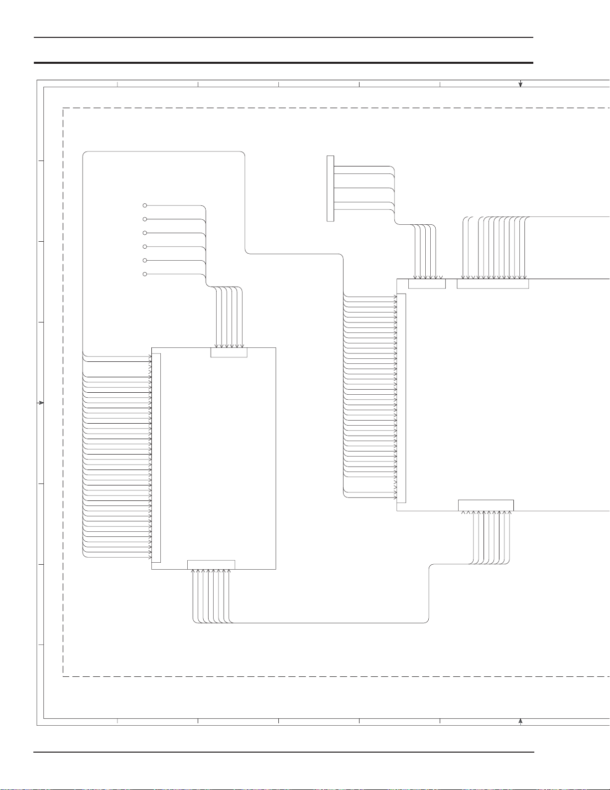
HMC-410
H
G
F
E
D
C
APPENDIX 4: SCHEMATIC DIAGRAM 3 OF 4
OPTIONAL (ROBOTIC INTERFACE OPTIONS SHOWN ONLY)
SEE SHEETS 1 AND 2 FOR STANDARD UNIT.
1
RXD
2
TXD
3
4
5
6
7
8
9
SERIAL COMMON
RTS
CTS
DO8 a
DO8 b
DO9 a
DO9 b
DO0 a
DO0 b
DO1 a
DO1 b
DO2 a
DO2 b
DO3 a
DO3 b
DO4 a
DO4 b
DO5 a
DO5 b
DO6 a
DO6 b
DO7 a
DO7 b
DI0 a
DI0 b
DI1 a
DI1 b
DI2 a
DI2 b
DI3 a
DI3 b
DI4 a
DI4 b
DI5 a
DI5 b
DI6 a
DI6 b
DI7 a
DI7 b
EXT. +15 VDC
EXT. COMMON
TB-1
TB-2
TB-3
TB-4
TB-5
TB-6
EXT. COMMON
EXT. +15 VDC
DI7 b
DI7 a
DI6 b
DI6 a
DI5 b
DI5 a
DI4 b
DI4 a
DI3 b
DI3 a
DI2 b
DI2 a
DI1 b
DI1 a
DI0 b
DI0 a
DO7 b
DO7 a
DO6 b
DO6 a
DO5 b
DO5 a
DO4 b
DO4 a
DO3 b
DO3 a
DO2 b
DO2 a
DO1 b
DO1 a
DO0 b
DO0 a
DO9 b
DO9 a
DO8 b
DO8 a
TERMINAL
BLOCK
GAS SHORTAGE a
GAS SHORTAGE b
WIRE SHORTAGE a
WIRE SHORTAGE b
WATER SHORTAGE a
WATER SHORTAGE b
40
39
38
37
36
35
34
33
32
31
30
29
28
27
26
25
24
23
22
21
20
J1
19
18
17
16
15
14
13
12
11
10
9
8
7
6
5
4
3
2
1
AMPHENOL
P.C. BOARD
J4
7
6
5
GAS SHORTAGE a
WIRE SHORTAGE b
WIRE SHORTAGE a
WATER SHORTAGE a
GAS SHORTAGE b
1
5
2
J3
483
2
1
J11
SERIAL PORT
WATER SHORTAGE b
634
6789101112
TXD
CTS
RXD
RTS
EXT. +15 VDC
EXT. COMMON
5 VDC
-15 VDC
SERIAL COMMON
1
546
2
3
J4
1
2
3
4
5
6
7
8
9
10
11
12
13
14
15
16
17
18
19
20
21
J5
22
23
24
25
26
27
28
29
30
31
32
33
34
35
36
37
38
39
40
ROBOTIC INTERFACE
5 VDC
967
12
131011
J2
P.C. BOARD
J3
97856
10
EXT. VOLT -
EXT. WFS +
EXT. WFS -
EXT. VOLT +
+15 VDC
8
EXT. VFB -
I2C SDA
COMMON
COMMON
5
342
EXT. IFB -
EXT. VFB+
EXT. IFB +
I2C SCL
1
COMMON
341
2
COMMON
B
A
Art # A-05057
A-6
EXT. WFS +
EXT. VFB -
EXT. WFS -
EXT. IFB +
EXT. VFB +
EXT. IFB -
EXT. VOLT +
EXT. VOLT -
12 11 10 9 8 76
July 27, 2005
Page 97
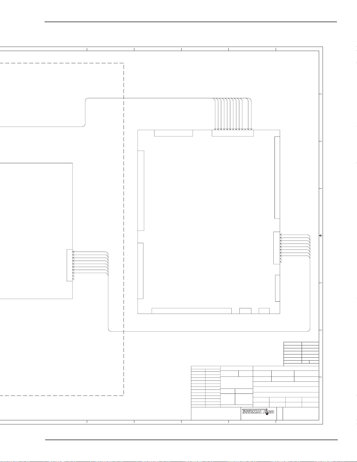
45 123
J3
COMMON
COMMON
2
163
I2C SDA
I2C SCL
COMMON
COMMON
587
4
J9
+15 VDC
-15 VDC
5 VDC
9
5 VDC
111013
EXT. +15 VDC
EXT. COMMON
12
HMC-410
H
G
F
J1
J7
MICROPROCESSOR
E
P.C. BOARD
LOCAL IFB +
1
LOCAL IFB -
2
LOCAL VFB +
3
LOCAL VFB -
4
LOCAL WFS +
5
10
6
7
8
9
LOCAL WFS LOCAL VOLT +
LOCAL VOLT -
D
LOCAL IFB +
1
LOCAL IFB -
2
LOCAL VFB +
3
LOCAL VFB -
4
LOCAL WFS +
5
10
6
7
8
9
LOCAL WFS LOCAL VOLT +
LOCAL VOLT -
J8
J1
J10
J2
J4
FINISH CODE PER
ACTIVITY
MATERIAL NO.
MATERIAL SPEC.
TITLE
DIAGRAM, CONNECTION & SCHEMATIC
± 3˚
DESCRIPTIVE DATA
HMC-410 (W/ ROBOTIC INTERFACE OPTIONS)
DESIGNED DRAWN DATE SCALE
CHECKED APPROVED RECORDS ITEM TYPE
ATC ATC 11-3-99
A THERMADYNE Company
TROY, OHIO 45373 , U.S.A.
R
REPLACED BY REPLACES
QUANTITY-U.M.
R
D
TECH. PUB.
OUTSIDE DISTR.
DWG. NO.SIZE
130
DISTRIBUTION TABLE
NONE
SHEET
870241
COMM. CLS.
FULLATC DBB 11-3-99
3
Art # A-05057
C
B
A
.0 ± .1
FILE NAME
±
ANGLES
0. ± 1.0mm
0.0 ± 0.4mm
0.00 ± 0.1mm
J5
PLOT DATE
METRIC
J6
CHANGE RECORD
E.C. No. DATE
CONFIDENTIAL: This drawing, including all information
contained thereon, is the exclusive and confidential property of
Thermal Arc Corporation of Troy, Ohio 45373 . This drawing is
not to be copied, reproduced, delivered or disclosed to others,
5 4 3 2 1
in whole or in part, except with express written permission.
870241S3 11-3-99
UNLESS OTHERWISE SPECIFIED
DIMENSIONS ARE IN INCHES/MILLIMETERS
TOLERANCES BELOW APPLY EXCEPT FOR
VENDOR DESIGNED PARTS AND ITEMS.
PRODUCED TO RECOGNIZED STANDARDS.
FRACT.
INCH
DECIMAL-INCH
.00 ± .02
.000 ± .003
DO NOT SCALE DRAWING
July 27, 2005
A-7
Page 98

HMC-410
APPENDIX 5: SCHEMATIC DIAGRAM 4 OF 4
789101112
H
OPTIONAL (ROBOTIC INTERFACE OPTIONS SHOWN ONLY)
SEE SHEETS 1 AND 2 FOR STANDARD UNIT.
G
F
J11 USED ON SPEC.
100050-2 ONLY
E
24
24
J11
47 RD
30
D
49 OR
6978
12345
48 BK
50 VT
24
24
51 GY
24
71 YL
3131313131
31
75 OR
76 VT
72 BR
74 BL
73 GY
5
243
6
1
J3
27
27
27
27
27
27
27
C
31
71 YL
72 BR
73 GY
TB-1
74 BL
75 OR
53412
76 VT
6
AMPHENOL
P.C. BOARD
J1
29
28
B
REAR
A
8
70 BR
22
J4
6
7
68 RD
69 YL
222222
22
67 BL
5
22
66 OR
324
65 BK
22
64 WT
1
63 GY
22
BOTTOM
A-8
Art # A-05058
12 11 10 9 8 7
July 27, 2005
Page 99

J4 USED ON SPEC.
100050-2 ONLY
HMC-410
456 123
H
J5
49 OR
50 VT
48 BK
47 RD
1
453
2
J4
ROBOTIC INTERFACE
23
3030303030
51 GY
6
24
P.C. BOARD
22
10
46 BL
32
45 PK
121311
43 TN
10
42 GY
9
323232
32323232323232
40 YL
38 WT
39 BK
41 VT
587
6
J2
25
26
37 BL
4
36 OR
3
J1
32
35 RD
2
34 BR
252525252525252525
25
25
35 RD
36 OR
37 BL
34 BR
1
J3
40 YL
38 WT
39 BK
5
798
6
1
243
J9
J7
MICROPROCESSOR
P.C. BOARD
JP2
1
2
53 BL
1
2
3
4
5
6
7
8
9
10
54 WT
55 BK
56 YL
57 RD
58 GY
59 OR
60 BR
33
33
33
33
33
33
33
33
J8
3
3
3
2
2
1
1
JP3
JP4
41 VT
32
42 GY
43 TN
10
33
J10
45 PK
121311
46 BL
25
G
J1
F
53 BL
1
2
3
4
5
6
7
8
9
10
54 WT
55 BK
56 YL
57 RD
58 GY
59 OR
60 BR
26
26
26
26
26
26
26
26
E
J2
J3
6
879
324
5
1
J6
J5
J4
D
July 27, 2005
69 YL
67 BL
68 RD
70 BR
FRONT
6 5 4 3 2 1
64 WT
66 OR
65 BK
63 GY
28
28
282828
282828
TECH. PUB.
OUTSIDE DISTR.
CHANGE RECORD
E.C. No. DATE
CONFIDENTIAL: This drawing, including all information
contained thereon, is the exclusive and confidential property of
Thermal Arc Corporation of Troy, Ohio 45373 . This drawing is
not to be copied, reproduced, delivered or disclosed to others,
in whole or in part, except with express written permission.
FILE NAME
870241S4 11-3-99
UNLESS OTHERWISE SPECIFIED
DIMENSIONS ARE IN INCHES/MILLIMETERS
TOLERANCES BELOW APPLY EXCEPT FOR
VENDOR DESIGNED PARTS AND ITEMS.
PRODUCED TO RECOGNIZED STANDARDS.
FRACT.
±
INCH
DECIMAL-INCH
.0 ± .1
.00 ± .02
.000 ± .003
DO NOT SCALE DRAWING
PLOT DATE
ANGLES
± 3˚
METRIC
0. ± 1.0mm
0.0 ± 0.4mm
0.00 ± 0.1mm
A THERMADYNE Company
TROY, OHIO 45373 , U.S.A.
FINISH CODE PER
ACTIVITY
MATERIAL NO.
MATERIAL SPEC.
TITLE
DIAGRAM, CONNECTION & SCHEMATIC
DESCRIPTIVE DATA
HMC-410 (W/ ROBOTIC INTERFACE OPTIONS)
DESIGNED DRAWN DATE SCALE
CHECKED APPROVED RECORDS ITEM TYPE
ATC ATC 11-3-99
R
REPLACED BY REPLACES
QUANTITY-U.M.
DWG. NO.SIZE
R
D
130
DISTRIBUTION TABLE
NONE
SHEET
870241
COMM. CLS.
FULLATC DBB 11-3-99
4
Art # A-05058
C
B
A
A-9
Page 100
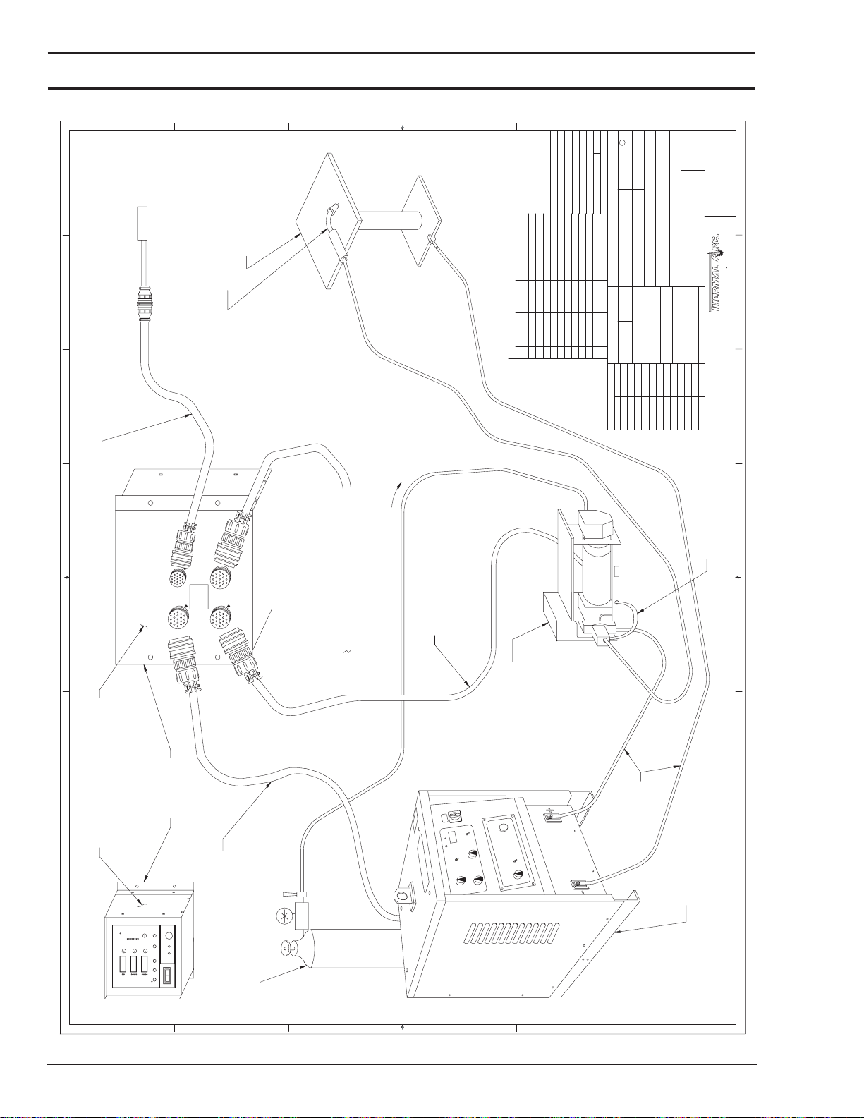
HMC-410
APPENDIX 6: SYSTEM OUTLINE 1 OF 2
F
(OPTIONAL)
WITH 15' CABLE
REMOTE PENDANT
(OPTIONAL)
EXTENSION CABLE
170486-X REMOTE PENDANT
E
WORK TABLE
WELDING GUN
D
C
SHEETS AFFECTED
REVISION CHART
1570
ECN NO.REV DATE
A 8-14-97 1, 2
1/92
150
8/97
TECH. PUB.
B
A
COMM. CLS.
DWG DTD
1-16-92
DISTRIBUTION TABLE
NONE
OUTSIDE DISTR.
REPLACED BY REPLACES
QUANTITY-U.M.
ACTIVITY
MATERIAL NO.
FINISH CODE PER
PLOT DATE
FILE NAME
170921S1 8-14-97
UNLESS OTHERWISE SPECIFIED
DIMENSIONS ARE IN INCHES/MILLIMETERS
CHANGE RECORD
E.C. No. DATE
1) AA6822 5-3-95
A
FULLTLT DBB 8-14-97
TLT TLT 1-16-92
CHECKED APPROVED RECORDS ITEM TYPE
DESIGNED DRAWN DATE SCALE
OUTLINE, SYSTEM
HMC-410
DESCRIPTIVE DATA
TITLE
MATERIAL SPEC.
± 3˚
0.00 ± 0.1mm
0.0 ± 0.4mm
0. ± 1.0mm
ANGLES
±
.0 ± .1
.00 ± .02
DO NOT SCALE DRAWING
.000 ± .003
DECIMAL-INCH
FRACT.
INCH
TOLERANCES BELOW APPLY EXCEPT FOR
VENDOR DESIGNED PARTS AND ITEMS.
PRODUCED TO RECOGNIZED STANDARDS.
1 OF 2
Art # A-04475
SHEET
170921
123654
DWG. NO.SIZE
C
R
R
TROY, OHIO 45373, U.S.A.
A THERMADYNE Company
CONFIDENTIAL: This drawing, including all information
contained thereon, is the exclusive and confidential property of
Thermal Arc Corporation of Troy, Ohio 45373 . This drawing is
not to be copied, reproduced, delivered or disclosed to others,
in whole or in part, except with express written permission.
CONTROL PANEL
AUTOMATIC/SEMIAUTOMATIC
78 56 4 3 2 1
HMC-410
FRONT REAR
MTG.
BRACKETS
AUX
REM
PS
FDR
170552-X POWER SOURCE
CONTROL CABLE (1 REQUIRED)
GAS SUPPLY
TO GAS VALVE
170487-X AUXILIARY
INTERFACE CABLE (OPTIONAL)
(1 REQUIRED)
170552-X FEEDHEAD
ASSEMBLY CONTROL CABLE
4 ROLL FEEDHEAD
ASSEMBLY (1 REQUIRED)
CABLES
WELDING
GUN SWITCH LEADS
78
POWER SOURCE
A-10
F
E
D
C
B
A
July 27, 2005
 Loading...