

Page 1

HEFTY®II STAINLESS
SEMIAUTOMATIC, SOLID STATE CONTROLLED
VOLTAGE SENSING WIRE FEEDER
For the Following Specs:
100052-1
•
OWNER’S MANUAL Number 430429-456 (Rev AB)
Revised June 5, 2000
IMPORTANT: Readtheseinstructionsbeforeinstalling,operating, or servicing this system.
THERMAL ARC INC., TROY, OHIO 45373-1085, U.S.A.
Page 2

430429-456
TABLE OF CONTENTS
INTRODUCTION 1
How To Use This Manual ..................................1-1
Equipment Identification ..................................1-1
Receipt Of Equipment ...................................1-1
ARC WELDING SAFETY INSTRUCTIONS AND WARNINGS 2
DESCRIPTION OF EQUIPMENT 3
General ...........................................3-1
Product Specifications ...................................3-1
Features/Benefits ......................................3-2
Meanings Of Markings And Graphical Symbols ......................3-3
Front Panel Controls And Connections ...........................3-4
Internal Controls And Connections (Component Side) ...................3-5
Internal Controls And Connections (Wire Spool Side) ...................3-6
Description Of Feedhead Assembly ............................3-6
Power Source Compatibility ................................3-7
Available Options ......................................3-8
INSTALLATION 4
Connections .........................................4-1
Installation Of Welding Wire Spool .............................4-1
Adjustment Of Spool Tension ................................4-1
Input And Output Wire Guide Installation ..........................4-1
Selection And Installation Of Feed Rolls ..........................4-1
Welding Gun Compatibility And Installation .........................4-2
Threading Wire Into Feedhead ...............................4-2
OPERATION 5
Prewelding Procedure ...................................5-1
Welding Procedure .....................................5-2
Welding In CC Mode vs. CV Mode .............................5-2
Theory Of Operation ....................................5-2
Adjusting Burnback Time ..................................5-2
Calibrating Wire Feed Speed Meter ............................5-3
Protection And Safety Circuits ...............................5-3
MAINTENANCE 6
Cleaning Of The Unit ....................................6-1
Cleaning Of The Feed Rolls ................................6-1
Feedhead Maintenance ...................................6-1
Contactor Maintenance ...................................6-1
Gas Valve Maintenance ..................................6-1
TROUBLESHOOTING 7
Scope ............................................7-1
Safety ............................................7-1
Troubleshooting Hints ....................................7-1
Troubleshooting Guide ...................................7-2
June 5, 2000 Revised Page 1
Page 3

430429-456
TABLE OF CONTENTS
PARTS LIST 8
Equipment Identification ..................................8-1
How To Use This Parts List .................................8-1
DIAGRAMS
WARRANTY
Page 2 November 17, 1999
Page 4

INTRODUCTION
430429-456
INTRODUCTION
How To Use This Manual:
This Owner’s Manual usually applies to just the
underlined specification or part numbers listed on
the cover. If none are underlined, they are all covered by this manual.
Throughout this manual, the words WARNING,
CAUTION, and NOTE may appear. Pay particular
attention to the information provided under these
headings. These special annotationsareeasily recognized as follows:
WARNING gives information regarding possible personal injury. Warnings will be enclosed
in a box such as this.
CAUTION refers to possible equipment
damage. Cautions will be shown in bold
type.
NOTE offers helpful information concerningcertainoperatingprocedures. Notes will
be shown in italics.
appear on a nameplate attached to the control
panel. In some cases, the nameplate may be attached to the rearpanel.Equipment which does not
have a control panelsuch as gunand cable assemblies is identified only by the specification or part
number printed on the shipping container. Record
these numbers for future reference.
Receipt Of Equipment:
When you receivethe equipment, checkit against
the invoice to make sure it is complete and inspect
theequipmentforpossibledamageduetoshipping.
If there is any damage, notify the carrier immediately to file a claim. Furnish complete information
concerning damage claims or shipping errors to
Thermal Arc, Order Department, 2200 Corporate
Drive, Troy, Ohio 45373-1085. Include all equipment identification numbers as described above
along with a full description of the parts in error.
Move the equipment to the installation site before
uncrating the unit. Use care to avoid damaging the
equipment when using bars, hammers, etc., to uncrate the unit.
Equipment Identification:
The unit’s identification number (specification or
part number), model, and serial number usually
Additional copies of this manual may be purchased by contacting Thermal Arc at the address
given above. Include the Owner’s Manual number
and equipment identification numbers.
November 17, 1999 1-1
Page 5

430429-456
INTRODUCTION
This page intentionally left blank.
1-2 November 17, 1999
Page 6
ARC WELDING SAFETY INSTRUCTIONS AND WARNINGS
Instruction 830001
ARC WELDING SAFETY INSTRUCTIONS AND WARNINGS
ARC WELDING can be hazardous.
PROTECT YOURSELF AND OTHERS FROM POSSIBLE SERIOUS INJURY OR DEATH. KEEP CHILDREN AWAY. PACEMAKER
WEARERSKEEPAWAY UNTILCONSULTINGYOUR DOCTOR.DONOT LOSETHESEINSTRUCTIONS. READOPE RATING/INSTRUCTION MANUAL BEFORE INSTALLING, OPERATING OR SERVICING THIS EQUIPMENT.
Welding products and welding processes can cause serious injury or death, or damage to other equipment or property, if the operator does
not strictly observe all safety rules and take precautionary actions.
Safe practices have developed from past experience in the use of welding and cutting. These practices must be learned through study and
trainingbeforeusingthis equipment. Anyone not havingextensivetraining in welding and cuttingpracticesshould not attempt to weld. Certain
of the practices apply to equipment connected to power lines; other practices apply to engine driven equipment.
Safe practices are outlined in the American National Standard Z49.1 entitled:
other guides to what you should learn before operating this equipment are listed at the end of these safety precautions.
HAVE ALL INSTALLATION, OPERATION, MAINTENANCE, AND REPAIR WORK PERFORMED ONLY BY QUALIFIED PEOPLE.
ELECTRIC SHOCK can kill.
Touchingliveelectrical partscancause fatal shocks
or severe burns. The electrode and work circuit is
electricallylivewhenevertheoutputison. The input
power circuit and machine internal circuits are also
livewhen poweris on.In semiautomaticorautomatic
wire welding, the wire, wire reel, drive roll housing,
and all metal parts touching the welding wire are
electrically live. Incorrectly installed or improperly
grounded equipment is a hazard.
1. Do not touch live electrical parts.
2. Wear dry, hole-free insulating gloves and body protection.
3. Insulate yourselffromwork and ground using dryinsulatingmats
or covers.
4. Disconnect input power or stop engine before installing or servicing this equipment. Lock input power disconnect switch open,
or remove line fuses so power cannot be turned on accidentally.
5. Properly install and ground this equipment according to its
Owner’s Manual and national, state, and local codes.
SAFETY IN WELDING AND CUTTING. This publication and
6. Turn off all equipment when not in use. Disconnect power to
equipment if it will be left unattended or out of service.
7. Use fully insulated electrode holders. Never dip holder in water
to cool it or lay it down on the ground or the work surface.Donot
touch holders connected to two welding machines at the same
time or touch other people with the holder or electrode.
8. Do notuse worn, damaged,undersized,or poorly splicedcables.
9. Do not wrap cables around your body.
10. Ground the workpiece to a good electrical (earth) ground.
11. Do not touch electrode while in contact with the work (ground)
circuit.
12. Useonlywell-maintained equipment.Repair orreplacedamaged
parts at once.
13. In confined spaces or damp locations, do not use a welder with
AC output unless it is equipped with a voltage reducer. Use
equipment with DC output.
14. Wear a safety harness to prevent falling if working above floor
level.
15. Keep all panels and covers securely in place.
ARC RAYS can burn eyes and skin;
NOISE can damage hearing.
Arc rays from the welding process produce intense
heat and strong ultraviolet rays that can burn eyes
and skin. Noise from some processes can damage
hearing.
Eye protection filter shade selector for welding or cutting (goggles or helmet), from AWS A6.2-73.
Welding or Cutting
Operation
Torch soldering
Torch brazing
Oxygen cutting
Light
Medium
Heavy
Gas welding
Light
Medium
Heavy
Shielded metal-arc welding
(stick) electrodes
Electrode Size
Metal Thickness
or Welding Current
—
—
Under 1 in., 25 mm
1 to 6 in., 25-150 mm
Over 6 in., 150 mm
Under 1/8 in., 3 mm
1/8 to 1/2 in., 3-12 mm
Over 1/2 in., 12 mm
Under 5/32 in., 4 mm
5/32 to 1/4 in., 4 to 6.4 mm
Over 1/4 in., 6.4 mm
Filter
Shade
No.
2
3or4
3or4
4or5
5or6
4or5
5or6
6or8
10
12
14
1. Wear a welding helmet fitted with a proper shade of filter (see
ANSI Z49.1 listed in Safety Standards) to protect your face and
eyes when welding or watching.
2. Wear approved safety glasses. Side shields recommended.
3. Use protective screens or barriers to protect others from flash
and glare; warn others not to watch the arc.
4. Wear protective clothing made from durable, flame-resistant
material (wool and leather) and foot protection.
5. Use approved ear plugs or ear muffs if noise level is high.
Welding or Cutting
Operation
Gas metal-arc welding (MIG)
Non-ferrous base metal
Ferrous base metal
Gastungstenarcwelding (TIG)
Atomic hydrogen welding
Carbon arc welding
Plasma arc welding
Carbon arc air gouging
Light
Heavy
Plasma arc cutting
Light
Medium
Heavy
Electrode Size
Metal Thickness
or Welding Current
All
All
All
All
All
All
Under 300 Amp
300 to 400 Amp
Over 400 Amp
May 8, 1996 2-1
Filter
Shade
No.
11
12
12
12
12
12
12
14
9
12
14
Page 7
ARC WELDING SAFETY INSTRUCTIONS AND WARNINGS
Instruction 830001
FUMES AND GASES can be hazardous
to your health.
Weldingproducesfumesandgases.Breathingthese
fumes and gases can be hazardous to your health.
1. Keep your head out of the fumes. Do not breath the fumes.
2. If inside, ventilate the area and/or use exhaust at the arc to
remove welding fumes and gases.
3. If ventilation is poor, use an approved air-supplied respirator.
WELDING can cause fire or explosion.
Sparks and spatter fly off from the welding arc. The
flying sparks and hot metal, weld spatter, hot workpiece, and hot equipment cancausefiresandburns.
Accidental contact of electrode or welding wire to
metal objects can cause sparks, overheating, or fire.
1. Protect yourself and others from flying sparks and hot metal.
2. Do not weld where flying sparks can strike flammable material.
3. Remove all flammables within 35 ft (10.7 m) of the welding arc.
If this is not possible, tightly cover them with approved covers.
4. Be alert that welding sparks and hot materials from welding can
easily go through small cracks and openings to adjacent areas.
4. Read the Material Safety Data Sheets (MSDSs) and the manufacturer’s instruction for metals, consumables, coatings, and
cleaners.
5. Work in a confined space only if it is well ventilated, or while
wearing an air-supplied respirator. Shielding gases used for
welding can displace air causing injury or death. Be sure the
breathing air is safe.
6. Do not weld in locations near degreasing, cleaning, or spraying
operations. The heat and raysofthearccanreactwithvapors to
form highly toxic and irritating gases.
7. Do not weld on coated metals, such as galvanized, lead, or
cadmium plated steel, unless the coating is removed from the
weld area, the area is well ventilated, and if necessary, while
wearing an air-supplied respirator. The coatings and any metals
containing these elements can give off toxic fumes if welded.
5. Watch for fire, and keep a fire extinguisher nearby.
6. Be aware that welding on a ceiling, floor, bulkhead, or partition
can cause fire on the hidden side.
7. Do not weld on closed containers such as tanks or drums.
8. Connect work cable to the work as close to the welding area as
practical to prevent welding current from traveling long, possibly
unknown paths and causing electric shock and fire hazards.
9. Do not use welder to thaw frozen pipes.
10. Remove stick electrode from holder or cut off welding wire at
contact tip when not in use.
11. Wear oil-free protective garments such as leather gloves, heavy
shirt, cuffless trousers, high shoes, and a cap.
FLYING SPARKS AND HOT METAL can
cause injury.
Chipping and grinding cause flying metal. As welds
cool, they can throw off slag.
CYLINDERS can explode if damaged.
Shielding gas cylinderscontaingasunderhighpressure. If damaged, a cylinder can explode. Since gas
cylinders are normally part of the welding process,
be sure to treat them carefully.
1. Protectcompressed gascylinders fromexcessiveheat,mechanical shocks, and arcs.
2. Install and secure cylinders in an upright position by chaining
themtoa stationarysupport orequipment cylinderracktoprevent
falling or tipping.
ENGINE EXHAUST GASES can kill.
Engines produce harmful exhaust gases.
1. Wear approved face shield or safety goggles. Side shields recommended.
2. Wear proper body protection to protect skin.
3. Keep cylindersawayfrom any welding orotherelectricalcircuits.
4. Never allow a welding electrode to touch any cylinder.
5. Use only correct shielding gas cylinders, regulators, hoses, and
fittings designed for the specific application; maintain them and
associated parts in good condition.
6. Turn face away from valve outlet when opening cylinder valve.
7. Keep protective cap in place over valve except when cylinder is
in use or connected for use.
8. Read and follow instructionsoncompressedgas cylinders, associated equipment, and CGA publication P-1 listed in Safety
Standards.
ENGINES can be hazardous.
1. Use equipment outside in open, well-ventilated areas.
2. If used in a closed area, vent engine exhaust outside and away
from any building air intakes.
2-2 May 8, 1996
Page 8
ARC WELDING SAFETY INSTRUCTIONS AND WARNINGS
Instruction 830001
ENGINE FUEL can cause fire or
explosion.
Engine fuel is highly flammable.
1. Stop engine before checking or adding fuel.
MOVING PARTS can cause injury.
Moving parts,suchasfans, rotors, and belts cancut
fingers and hands and catch loose clothing.
1. Keep all doors, panels, covers, and guards closed and securely
in place.
2. Stop engine before installing or connecting unit.
SPARKS can cause BATTERY GASES
TO EXPLODE; BATTERY ACID can
burn eyes and skin.
Batteriescontain acidandgenerateexplosivegases.
STEAM AND PRESSURIZED HOT
COOLANT can burn face, eyes, and
skin.
The coolantinthe radiator can beveryhot and under
pressure.
WARNING: This product, when used for welding or cutting, produces fumes or gases which contain chemicals known to the State
of California to cause birth defects and, in some cases, cancer. (California Health & Safety Code Sec. 25249.5 et seq.)
NOTE: Considerations About Welding And The Effects Of Low Frequency Electric And Magnetic Fields
The following is a quotation from the General Conclusions Section of the U.S. Congress, Office of Technology Assessment,
of Power Frequency Electric& Magnetic Fields — Background Paper, OTA-BP-E-63 (Washington, DC: U.S. Government Printing Office, May
1989): “... there is now a very large volume of scientific findings based on experiments at the cellular level and from studies with animals and
people which clearly establish that low frequency magnetic fields can interact with, and produce changes in, biological systems. While most of
this work is of very high quality, the results are complex. Current scientific understanding does not yet allow us to interpret the evidence in a
single coherent framework. Even more frustrating, it does not yet allow us to draw definite conclusions about questions of possible risk or to
offer clear science-based advice on strategies to minimize or avoid potential risks.”
To reduce magnetic fields in the workplace, use the following procedures:
1. Keep cables close together by twisting or taping them.
2. Arrange cables to one side and away from the operator.
2. Donotadd fuelwhilesmoking orifunit isnearany sparksoropen
flames.
3. Allow engine to cool before fueling. If possible, check and add
fuel to cold engine before beginning job.
4. Do not overfill tank — allow room for fuel to expand.
5. Do not spill fuel. If fuel is spilled,cleanupbeforestartingengine.
3. Have only qualified people remove guards or covers for mainte-
nance and troubleshooting as necessary.
4. Topreventaccidental starting duringservicing,disconnect nega-
tive (-) battery cable from battery.
5. Keep hands, hair, loose clothing, and tools away from moving
parts.
6. Reinstall panels or guards and close doors when servicing is
finished and before starting engine.
1. Always wear a face shield when working on a battery.
2. Stop engine before disconnecting or connecting battery cables.
3. Do not allow tools to cause sparks when working on a battery.
4. Do not use welder to charge batteries or jump start vehicles.
5. Observe correct polarity (+ and –) on batteries.
1. Do not remove radiator cap when engine is hot. Allow engine to
cool.
2. Wear gloves and put a rag over cap area when removing cap.
3. Allow pressure to escape before completely removing cap.
Biological Effects
3. Do not coil or drape cables around the body.
4. Keep welding power source and cables as far awayfrom body as
practical.
About Pacemakers:
The above procedures are among those also normally recommended for pacemaker wearers. Consult your doctor for complete information.
PRINCIPAL SAFETY STANDARDS
Safety inWeldingandCutting,ANSI Standard Z49.1, from American
Welding Society, 550 N.W. LeJeune Rd., Miami, FL 33126.
SafetyandHealthStandards, OSHA 29 CFR1910,fromSuperintendent of Documents, U.S. Government Printing Office, Washington,
D.C. 20402.
Recommended Safe Practices for the Preparation for Welding and
CuttingofContainersThatHaveHeldHazardousSubstances,American Welding Society Standard AWS F4.1, from American Welding
Society, 550 N.W. LeJeune Rd., Miami, FL 33126.
National Electrical Code, NFPA Standard 70, from National Fire
Protection Association, Batterymarch Park, Quincy, MA 02269.
Safe Handling of Compressed Gases in Cylinders, CGA Pamphlet
P-1, from Compressed Gas Association, 1235 Jefferson DavisHighway, Suite 501, Arlington, VA 22202.
Code forSafetyin Welding and Cutting,CSAStandard W117.2, from
Canadian Standards Association, Standards Sales, 178 Rexdale
Boulevard, Rexdale, Ontario, Canada M9W 1R3.
Safe Practices for Occupation and Educational Eye and Face Protection, ANSI Standard Z87.1, from American National Standards
Institute, 1430 Broadway, New York, NY 10018.
Cutting and Welding Processes, NFPA Standard 51B, from National
Fire Protection Association, Batterymarch Park, Quincy, MA 02269.
May 8, 1996 2-3
Page 9

ARC WELDING SAFETY INSTRUCTIONS AND WARNINGS
Instruction 830001
This page intentionally left blank.
2-4 May 8, 1996
Page 10
PRECAUTIONS DE SECURITE EN SOUDAGE A L'ARC
Instruction 830002
PRECAUTIONS DE SECURITE EN SOUDAGE A L′ARC
LE SOUDAGE A L′ARC EST DANGEREUX
PROTEGEZ-VOUS,AINSI QUE LES AUTRES, CONTRE LES BLESSURESGRAVES POSSIBLES OU LA MORT. NE LAISSEZ PAS LES
ENFANTSS’APPROCHER,NILES PORTEURSDE STIMULATEURCARDIAQUE (AMOINSQU’ILS N’AIENTCONSULTE UNMEDECIN).
CONSERVEZ CES INSTRUCTIONS.LISEZLEMANUELD’OPERATION OU LES INSTRUCTIONS AVANT D’INSTALLER, UTILISER OU
ENTRETENIR CET EQUIPEMENT.
Les produits et procédés de soudage peuvent sauser des blessures graves ou la mort, de même que des dommages au reste du matériel
et à la propriété,sil’utilisateur n’adhère pas strictement à toutes les règles de sécurité et ne prend pas les précautions nécessaires.
En soudage et coupage, des pratiques sécuritaires se sont développées suite à l’expériencepassée. Ces pratiques doivent être apprises
parétude ou entraînement avant d’utiliserl’equipement. Toute personne n’ayant pas suivi un entraînement intensif en soudage et coupage
ne devrait pas tenter de souder. Certaines pratiques concernent les équipements raccordés aux lignes d’alimentation alors que d’autres
s’adressent aux groupes électrogènes.
La norme Z49.1 de l’American National Standard, intitulée “SAFETY IN WELDING AND CUTTING” présente les pratiques sécuritaires à
suivre. Ce document ainsi que d’autres guides que vous devriez connaître avant d’utiliser cet équipement sont présentés à la fin de ces
instructions de sécurité.
SEULES DES PERSONNES QUALIFIEES DOIVENT FAIRE DES TRAVAUX D’INSTALLATION, DE REPARATION, D’ENTRETIEN ET
D’ESSAI.
L’ELECTROCUTION PEUT ETRE
MORTELLE.
Une décharge électrique peut tuer ou brûler gravement. L’électrode et le circuit de soudage sont sous
tension dès la mise en circuit. Le circuit d’alimentation et les circuits internes de l’équipement sont
aussi sous tension dès la mise en marche. En
soudage automatique ou semi-automatique avec
fil, ce dernier, le rouleau ou la bobine de fil, le
logement des galets d’entrainement et toutes les
pièces métalliques en contact avec le fil de soudage
sont sous tension. Un équipement inadéquatement
installé ou inadéquatement mis à la terre est dangereux.
1. Ne touchez pas à des pièces sous tension.
2. Portez des gants et des vêtements isolants, secs et non troués.
3. Isolez-vousdela pièceàsouder et delamise àlaterre aumoyen
de tapis isolants ou autres.
4. Déconnectez la prise d’alimentation de l’équipement ou arrêtez
le moteur avant de l’installer ou d’en faire l’entretien. Bloquez le
commutateurencircuit ouvertou enlevezlesfusibles del’alimentation afin d’éviter une mise en marche accidentelle.
5. Veuillez à installer cet équipement et à le mettre à la terre selon
le manuel d’utilisation et les codes nationaux, provinciaux et
locaux applicables.
LE RAYONNEMENT DE L′ARC PEUT
BRÛLER LES YEUX ET LA PEAU; LE
BRUIT PEUT ENDOMMAGER L′OUIE.
L’arc de soudage produit une chaleur et des
rayons ultraviolets intenses, susceptibles de
brûler les yeux et la peau. Le bruit causé par
certains procédés peut endommager l’ouïe.
1. Portez une casque de soudeur avec filtre oculaire de nuance
appropriée (consultez la norme ANSI Z49 indiquéeci-après)
6. Arrêtez tout équipement après usage. Coupez l’alimentation de
l’équipement s’il est hors d’usage ou inutilisé.
7. N’utilisezque desporte-électrodesbienisolés.Nejamaisplonger
les porte-électrodes dans l’eau pour les refroidir. Ne jamais les
laisser traîner par terre ou sur les pièces à souder. Ne touchez
pas aux porte-électrodes raccordés à deux sources de courant
en même temps. Ne jamais toucher quelqu’un d’autre avec
l’électrode ou le porte-électrode.
8. N’utilisez pas de câbles électriques usés, endommagés, mal
épissés ou de section trop petite.
9. N’enroulez pas de câbles électriques autour de votre corps.
10. N’utilisez qu’une bonne prise de masse pour la mise à la terre
de la pièce à souder.
11. Ne touchez pas à l’électrode lorsqu’en contact avec le circuit de
soudage (terre).
12. N’utilisez que des équipements en bon état. Réparez ou remplacez aussitôt les pièces endommagées.
13. Dans des espacesconfinésoumouillés,n’utilisezpasde source
de courant alternatif, à moins qu’il soit muni d’un réducteur de
tension. Utilisez plutôt une source de courant continu.
14. Portez un harnais de sécurité si vous travaillez en hauteur.
15. Fermez solidement tous les panneaux et les capots.
pour vous protéger le visageetlesyeuxlorsquevoussoudezou
que vous observez l’exécution d’une soudure.
2. Portezdeslunettes desécuritéapprouvées. Des écranslatéraux
sont recommandés.
3. Entourez l’aire de soudage de rideaux ou de cloisons pour
protéger les autres des coups d’arcoudel’éblouissement;
avertissez les observateurs de ne pas regarder l’arc.
4. Portez des vêtements en matériaux ignifuges et durables (laine
et cuir) et des chaussures de sécurité.
5. Portez un casque antibruit ou des bouchons d’oreille approuvés
lorsque le niveau de bruit est élevé.
8-V-96 2-1
Page 11
PRECAUTIONS DE SECURITE EN SOUDAGE A L'ARC
Instruction 830002
SELECTION DES NUANCES DE FILTRES OCULAIRES POUR LA PROTECTION DES YEUX EN COUPAGE ET SOUDAGE
Opération
de
Coupage ou soudage
Brasage tendre au chalumeau
Brasage fort au chalumeau
Oxycoupage
mince
moyen
épais
Soudage aux gaz
mince
moyen
épais
Soudage à l’arc avec
electrode enrobées (SMAW)
Soudage à l’arc sous gaz
avec fil plein (GMAW)
métaux non-ferreux
métaux ferreux
Soudage à l’arc sous gaz
avec électrode de tungstène (GTAW)
Soudage à l’hydrogène
atomique (AHW)
Soudage à l’arc avec
électrode de carbone (CAW)
Soudage à l’arc Plasma (PAW)
Gougeage Air-Arc avec
électrode de carbone
mince
épais
Coupage à l’arc Plasma (PAC)
mince
moyen
épais
( selon AWS A 8.2-73 )
Dimension d’électrode ou
Epaisseur de métal ou
Intensité de courant
toutes conditions
toutes conditions
moins de 1 po. (25 mm)
de 1 à 6 po. (25 à 150 mm)
plus de 6 po. (150 mm)
moins de 1/8 po. (3 mm)
de 1/8 à 1/2 po. (3 à 12 mm)
plus de 1/2 po. (12 mm)
moins de 5/32 po. (4 mm)
de 5/32 à 1/4 po. (4 à 6.4 mm)
plus de 1/4 po. (6.4 mm)
toutes conditions
toutes conditions
toutes conditions
toutes conditions
toutes conditions
toutes dimensions
moins de 300 ampères
de 300 à 400 ampères
plus de 400 ampères
Nuance de
de filtre
oculaire
2
3 ou 4
2 ou 3
4 ou 5
5 ou 6
4 ou 5
5 ou 6
6 ou 8
10
12
14
11
12
12
12
12
12
12
14
12
14
9
LES VAPEURS ET LESFUMEES SONT
DANGEREUSES POUR LA SANTE.
Le soudage dégage des vapeurs et des fumées
dangereuses à respirer.
1. Eloignez la tête des fumées pour éviter de les respirer.
2. A l’intérieur, assurez-vous que l’aire de soudage est bien ventilée ou que les fumées et les vapeurs sont aspirées à l’arc.
3. Si la ventilation est inadequate, portez un respirateur à adduc-
tion d’air approuvé.
4. Lisez les fiches signalétiques et les consignes du fabricant
relatives aux métaux, aux produitsconsummables, aux revêtements et aux produits nettoyants.
5. Ne travaillez dans un espace confiné que s’il est bien ventilé;
sinon, portez un respirateur à adduction d’air. Les gaz protecteurs de soudage peuvent déplacer l’oxygène de l’air et ainsi
causer des malaises ou la mort. Assurez-vous que l’air est
propre à la respiration.
6. Ne soudez pas à proximité d’opérations de dégraissage, de
nettoyage ou de pulvérisation. La chaleur et les rayons de l’arc
peuvent réagir avec des vapeurs et former des gaz hautement
toxiques et irritants.
7. Ne soudez des tôles galvanisées ou plaquées au plomb ou au
cadmium que sileszonesà souder ont été grattées à fond, que
si l’espace est bien ventilé;sinécessaire portez un respirateur
à adductiond’air.Car ces revêtementsettout métal qui contient
cesélémentspeuventdégagerdes fuméestoxiques aumoment
du soudage.
2-2 8-V-96
Page 12
PRECAUTIONS DE SECURITE EN SOUDAGE A L'ARC
Instruction 830002
LE SOUDAGE PEUT CAUSER UN INCENDIE OU UNE EXPLOSION
L’arc produit des étincellies et des projections. Les
particules volantes, le métal chaud, les projections
de soudure et l’équipement surchauffé peuvent
causer un incendie et des brûlures. Le contact
accidentel de l’électrode ou du fil-électrode avec un
objet métallique peut provoquer des étincelles, un échauffement
ou un incendie.
1. Protégez-vous, ainsi que les autres, contre les étincelles et du
métal chaud.
2. Ne soudez pas dans un endroit où des particules volantes ou
des projections peuvent atteindre des matériaux inflammables.
3. Enlevez toutes matières inflammables dans un rayon de 10, 7
mètres autour de l’arc, ou couvrez-les soigneusement avec des
bâches approuvées.
LES ETINCELLES ET LES PROJECTIONS BRULANTES PEU VENT
CAUSER DES BLESSURES.
LES BOUTEILLES EN DOMMAGEES
PEUVENT EXPLOSER
Les bouteilles contiennent des gaz protecteurs
sous haute pression.Desbouteillesendommagées
peuvent exploser. Comme les bouteilles font normalement partie du procédé de soudage, traitezles avec soin.
1. Protégez les bouteilles de gaz comprimé contre les sources de
chaleur intense, les chocs et les arcs de soudage.
2. Enchainez verticalement les bouteilles à un support ou à un
cadre fixe pour les empêcher de tomber ou d’être renversées.
3. Eloignez les bouteilles de tout circuit électrique ou de tout
soudage.
4. Méfiez-vous des projectionsbrulantesde soudage susceptibles
de pénétrerdansdesaires adjacentes pardepetitesouvertures
ou fissures.
5. Méfiez-vous des incendies et gardez un extincteur à portéede
la main.
6. N’oubliez pas qu’une soudure réalisée sur un plafond, un
plancher, une cloison ou une paroi peut enflammer l’autre côté.
7. Ne soudez pas un récipient fermé, tel un réservoir ou un baril.
8. Connectez le câble de soudageleplus près possible delazone
de soudage pour empêcher le courant de suivre un long parcours inconnu, et prévenir ainsi les risques d’électrocution et
d’incendie.
9. Ne dégelez pas les tuyaux avec un source de courant.
10. Otez l’électrode du porte-électrode ou coupezle filautube-contact lorsqu’inutilisé après le soudage.
11. Portez des vêtements protecteurs non huileux, tels des gants
en cuir, une chemise épaisse, un pantalon revers, des bottines
de sécurité et un casque.
Le piquage et le meulage produisent des particules métalliques
volantes. En refroidissant, la soudure peut projeter du éclats de
laitier.
1. Portez un écran facial ou des lunettes protectrices approuvées.
Des écrans latéraux sont recommandés.
2. Portez des vêtements appropriés pour protéger la peau.
4. Empêchez tout contact entre une bouteille et une électrode de
soudage.
5. N’utilisez que des bouteilles de gaz protecteur, des détendeurs,
des boyauxs et des raccords conçus pour chaque application
spécifique; ces équipements et les pièces connexes doivent
être maintenus en bon état.
6. Ne placez pas le visage face à l’ouverture du robinet de la
bouteille lors de son ouverture.
7. Laissez en place le chapeau de bouteille sauf si en utilisation
ou lorsque raccordé pour utilisation.
8. Lisez et respectez les consignes relatives aux bouteilles de gaz
comprimé et aux équipements connexes, ainsi que la publication P-1 de la CGA, identifiée dans la liste de documents
ci-dessous.
LES MOTEURS PEUVENT ETRE DANGEREUX
LES GAZ D’ECHAPPEMENT DES
MOTEURS PEUVENT ETRE MORTELS.
Les moteurs produisent des gaz d’échappement
nocifs.
LE CARBURANT PEUR CAUSER UN INCENDIE OU UNE EXPLOSION.
Le carburant est hautement inflammable.
1. Arrêtez le moteur avant de vérifier le niveau de
carburant ou de faire le plein.
1. Utilisez l’équipement à l’extérieur dans des aires ouvertes et
bien ventilées.
2. Si vous utilisez ces équipements dans un endroit confiné, les
fumées d’échappement doivent être envoyées à l’extérieur, loin
des prises d’air du bâtiment.
2. Ne faites pas le plein en fumant ou proche d’une source
d’étincelles ou d’une flamme nue.
3. Si c’est possible, laissez le moteur refroidir avant de faire le
plein de carburant ou d’en vérifier le niveau au début du
soudage.
4. Ne faites pas le plein de carburant à ras bord: prévoyez de
l’espace pour son expansion.
5. Faitesattentiondene pas renverserdecarburant.Nettoyez tout
carburant renversé avant de faire démarrer le moteur.
8-V-96 2-3
Page 13
PRECAUTIONS DE SECURITE EN SOUDAGE A L'ARC
Instruction 830002
DES PIECES EN MOUVEMENT PEUVENT CAUSER DES BLESSURES.
Despiècesen mouvement,telsdes ventilateurs,des
rotors et des courroies peuvent couper doigts et
mains, ou accrocher des vêtements amples.
1. Assurez-vous que les portes, les panneaux, les capots et les
protecteurs soient bien fermés.
2. Avant d’installer ou de connecter un système,arrêtezlemoteur.
DESETINCELLESPEUVENT FAIREEXPLOSER UN ACCUMULATEUR;
L’ELECTROLYTE D’UN ACCUMULATEUR PEUT BRULER LA PEAU ET
LES YEUX.
Les accumulateur s contiennent de l’électr oly te
acide et dégagent des vapeurs explosives.
LA VAPEUR ET LE LIQUIDE DE REFROIDISSEMENT BRULANT SOUS
PRESSION PEU VENT BRULER LA
PEAU ET LES YEUX.
Le liquide de refroidissement d’un radiateur peut
être brûlant et sous pression.
3. Seules des personnes qualifiées doivent démonter des protecteurs ou des capots pour faire l’entretien ou le dépannage
nécessaire.
4. Pour empêcher un démarrage accidentel pendant l’entretien,
débranchez le câble d’accumulateur à la borne négative.
5. N’approchez pas les mains ou les cheveux de pièces en mouvement; elles peuvent aussi accrocher des vêtements amples
et des outils.
6. Réinstallez les capots ou les protecteurs et fermez les portes
après des travaux d’entretien et avant de faire démarrer le
moteur.
1. Portez toujours un écran facial en travaillant sur un accumulateur.
2. Arrêtez le moteur avant de connecter ou de déconnecter des
câbles d’accumulateur.
3. N’utilisez que des outils anti-étincelles pour travailler sur un
accumulateur.
4. N’utilisez pas une source de courant de soudage pour charger
un accumulateur ou survolter momentanément un véhicule.
5. Utilisez la polarité correcte (+ et –) de l’accumulateur.
1. N’ôtez pas le bouchon de radiateur tant que le moteur n’est pas
refroidi.
2. Mettez desgantsetposezun torchon sur le bouchon pourl’ôter.
3. Laissez la pression s’échapper avant d’ôter complètement le
bouchon.
PRINCIPALES NORMES DE SECURITE
SafetyinWeldingandCutting, normeANSI Z49.1,AmericanWelding
Society, 550 N.W. LeJeune Rd., Miami, FL 33128.
Safety and Health Standards, OSHA 29 CFR 1910, Superintendent
of Documents, U.S. Government Printing Office, Washington, D.C.
20402.
Recommended Safe Practices for the Preparation for Welding and
CuttingofContainersThatHaveHeldHazardousSubstances,norme
AWS F4.1, American Welding Society, 550 N.W. LeJeune Rd.,
Miami, FL 33128.
National Electrical Code, norme 70 NFPA, National Fire Protection
Association, Batterymarch Park, Quincy, MA 02269.
Safe Handling of Compressed Gases in Cylinders, document P-1,
Compressed Gas Association, 1235 JeffersonDavisHighway,Suite
501, Arlington, VA 22202.
Code for Safety in Welding and Cutting, norme CSA W117.2 Association canadienne de normalisation, Standards Sales, 276 Rexdale
Boulevard, Rexdale, Ontario, Canada M9W 1R3.
Safe Practices for Occupation and Educational Eye and Face Protection, norme ANSI Z87.1, American National Standards Institute,
1430 Broadway, New York, NY 10018.
Cutting and Welding Processes, norme 51B NFPA, National Fire
Protection Association, Batterymarch Park, Quincy, MA 02269.
2-4 8-V-96
Page 14
DESCRIPTION OF EQUIPMENT
DESCRIPTION OF EQUIPMENT
430429-456
General:
The HEFTY II STAINLESS is a portable, solid state
controlled,voltage sensing wire feederthat operates on
arc voltage and can be usedwithmostconstant voltage
(CV)andconstant current(CC)DC-typepowersources.
Theonlyconnectionrequiredbetweenthepowersource
and the wire feeder is the welding cable.
The unique design of this wire feeder allows operation in a constant wire feed speed mode when
used with CV power sources, and in a voltage
sensing wire feed speed mode (wire feed speed
varies with respect to arc voltage) when used with
CC power sources.
The stainless steel case totally encloses the solid
state control circuitry, welding wire, and wire drive
system. A hinged, latched door allows quick and
easy access to the welding wire and feedhead
assembly that features quick change, gear-driven
feed rolls and a hand operated knob for clamping
the welding gun into the feedhead.
The HEFTY II STAINLESS comes with an abundance of standard features, which include: (1)
on/off rocker switch, (2) wire feed speed control
knob, (3) inch/purge switch, (4) carrying handle, (5)
contactor, (6) gas valve, (7) CC/CV mode switch,
(8) input circuit breaker forcomplete system protection, (9) electronic controlled protection circuitry to
protect against an undervoltage, an overvoltage, a
voltage spike, a shorted or locked motor, a shorted
contactor coil, and a shorted gas valve, (10) electroniccontrolleddynamicbrake, (11) electroniccontrolled current limit to motor, (12) electronic
controlledstart circuit for improved arc starting,(13)
low voltage gun trigger circuit for operator safety,
and (14) a feed roll kit for 0.035 and 0.045 size filler
wire.
The HEFTY II STAINLESS has been designed to
comply with CSA NRTL/C and NEMA EW 3 standards.
Product Specifications:
Input Voltage Range ..........................15 - 100 VDC
Input Frequency..................................... 0 Hz (DC)
Maximum Input Current.............................. 8 Amps
Wire Speed Range
(Dependent On Arc Voltage).......... 50 - 700 IPM
..................................................... (1.3 - 17.8 MPM)
Wire Sizes ........................................ 0.024 - 5/64"
......................................................... (0.6 - 2.0 mm)
Maximum Wire Spool Capacity...... 12" (304.8 mm)
....................................................... 30Lbs. (13.6 kg)
Feed Rolls............................. 2 (Both Gear Driven)
Welding Current (I)........... 330A at 60% Duty Cycle
Welding Gun Diameter....................... 5/8" Nominal
Maximum Shielding Gas Inlet Pressure ....... 75 PSI
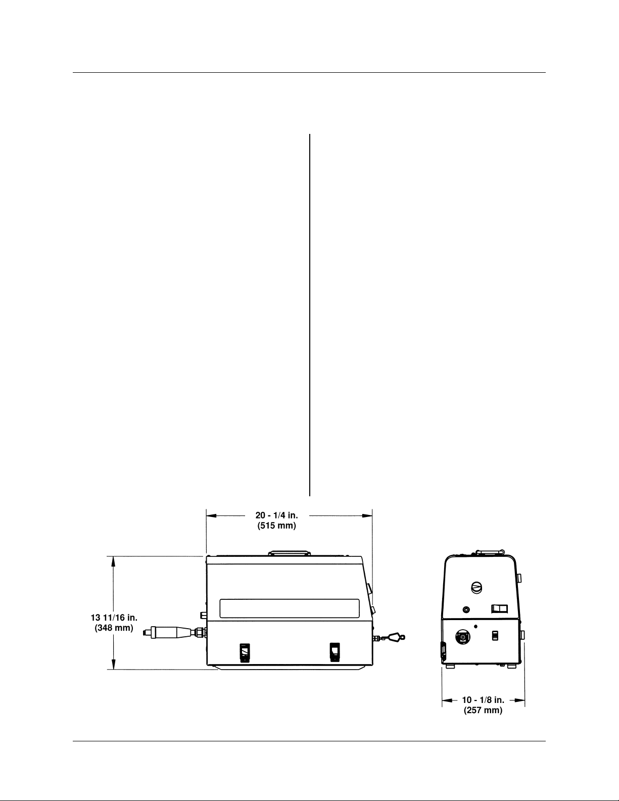
Weight (Less Wire)...................... 38 Lbs. (17.2 kg)
Approvals.......................................... CSA NRTL/C
........................................................... NEMA EW 3
Figure 3-1 Dimensional Information
June 5, 2000 Revised 3-1
Page 15

430429-456
DESCRIPTION OF EQUIPMENT
Features/Benefits:
1. Operates On Arc Voltage
2. Voltage Sensing Control Circuit With
CC/CV Switch
3. Solid State Circuitry
4. Polarity Insensitive
5. Electronic Controlled Start Circuit
6. Electronic Brake
7. Standard Contactor
8. Standard Gas Valve
9. Powerful, Permanent Magnet DC Drive
Motor
A. Can be used with most constant current (CC) or con-
stant voltage (CV) DC-type power sources
B. No control cables required
A. Allows voltagesensingwirefeedspeedoperationwhen
used with CC power sources
B. Allows constant wire feed speed operation when used
with CV power sources
A. Improves wire speed accuracy
B. Compensates for motor load variations
C. Providescurrentlimittocontactor, gas valve,andmotor
A. Operates on either straight or reverse polarity
A. Enhances arc starting performance with CC power
sources
A. Solid state control of an electronic brake offers quick
stopping of the motor to prevent wire overrun
A. Allows the weldingwiretoremainelectrically“cold”until
the gun switch trigger is depressed
B. Increases operator safety
A. Controls the “on/off” flow of shielding gas
A. Accommodatesthefastspeed demands of small diameter
wire
B. Accommodates the low speed,hightorquedemandsof
large diameter wire
10. Replaceable Motor Brushes
11. Needle Bearing Construction On Motor
Output Shaft
12. Input Circuit Breaker
13. Electronic Controlled Protection Circuitry
14. Stainless Steel Case
15. Standard Inch/Purge Switch
16. Carrying Handle
17. Quick Change Feed Rolls
18. Gun Clamp Knob
19. Feed Roll Pressure Release
A. Provides economical means of extending motor life
A. Reduces friction and extends bearing life over a
sleeving bearing
A. Ensures complete system protection
A. Protects electronics from undervoltage, overvoltage,
and voltage spikes.
B. Protects electronics from a shorted or locked motor
C. Protects electronics from a shorted contactor coil
D. Protects electronics from a shorted gas valve coil
A. Provides strength in a small, portable, light weight
package
B. Allows easy access for difficult to reach jobs
A. Allows “cold” inching of wire at set wire feed speed
B. Allows purging of gas without running wire
A. Promotes portability
A. Allows operator to change feed rolls without the use of
tools
B. Both feed rollsare gear drivenfor better feeding ofwire
A. Allows operator to secure welding gun without the use
of tools
A. Allows operator to adjust feed roll pressure without the
use of tools
B. Allows operator to change feed rolls or wire while
retaining preset feed roll pressure
3-2 November 17, 1999
Page 16

Meanings Of Markings And Graphical Symbols:
Signifies an OFF position
Signifies an ON position
Signifies voltage input
Signifies a wire feed function
Signifies a voltage or voltage control
430429-456
DESCRIPTION OF EQUIPMENT
Signifies amperage
Signifies cycles per second
Signifies a welding gun
Signifies the feeding of wire towards the work piece with output voltage off
Signifies a purging of gas
Signifies a constant voltage characteristic
Signifies a constant current (drooping) characteristic
Signifies a circuit breaker in an electrical circuit
I
I
X
June 5, 2000 Revised 3-3
Signifies welding current
Signifies duty cycle
Page 17

430429-456
DESCRIPTION OF EQUIPMENT
Signifies a percentage
Signifies an analog meter function
Front Panel Controls And
Connections:
See Figure 3-2 for details.
1. WELDING GUN CABLE CONNECTION - The
welding gun cable is connected to the wire feeder
at this point. Connections must be tight; otherwise,
arcing or overheating could result.
2. WIRE FEED SPEED CONTROL - This knob
controls the wire feed speed. The wire feed speed
control can be adjustedduringsetup or actual welding.
3. ARC VOLTAGE CONTROL (OPTIONAL) This knob controls the arc voltage from the power
source. The arc voltage control can be adjusted
during setup or actual welding.
NOTE: The power source must be in the
remote position for this function to work.
4. ARC VOLTAGE METER (OPTIONAL) - The
arc voltage meter displaystheactual voltage output
of the power source.
5. WIRE FEED SPEED METER (OPTIONAL) Thewirefeedspeedmeterdisplaystheactualwirefeed
speed output of the wire feeder.
6. POWER ON/OFF SWITCH - This switch controls input power only to the wire feeder and not to
the power source.
Figure 3-2 Front Panel Controls And Connections
3-4 November 17, 1999
Page 18

Internal Controls And
Connections (Component Side):
See Figure 3-3 for details.
7. CC/CV MODE SWITCH - TheCC position provides a voltage sensing wire feed speed mode of
operation for use with constant current (CC) power
sources. The CV position provides a constant wire
feed speed mode of operation for use with constant
voltage (CV) power sources.
NOTE: This switch does not select a CC or
CV mode of operation. The mode ofoperationissetbythe type of power source being
used.
8. INPUT CIRCUIT BREAKER - This circuit
breakerprovidescompletesystemprotection for the
wire feeder in the case of a fault or overload condition.
430429-456
DESCRIPTION OF EQUIPMENT
9. 12 VDC DRIVER PCB - The 12 VDC driver
printed circuit board (PCB) is primarily responsible
for controlling the contactor and gas valve.
10. MOTOR CONTROL PCB - The motor control
printed circuit board (PCB) is primarily responsible
for controlling the output speed of the motor.
11. CONTACTOR - The contactor controls the
“on/off” flow of weld current from the power source.
When the contactor is open, the welding wire is
electrically“cold.” Whenthecontactorisclosed,the
welding wire is electrically “hot.”
CAUTION: The contactor is rated for
330 amps of weld current at a 60% duty
cycle. Exceeding the current or duty cycle ratings will damage or shorten the
life of the contactor.
12. GAS VALVE - The gas valve controls the
“on/off” flow of shielding gas through the welding
gun.
Figure 3-3 Internal Controls And Connections
(Component Side)
June 5, 2000 Revised 3-5
Page 19

430429-456
DESCRIPTION OF EQUIPMENT
Figure 3-4 Internal Controls And Connections
(Wire Spool Side)
Internal Controls And
Connections (Wire Spool Side):
See Figure 3-4 for details.
13. WELD CABLE CONNECTION -This is where
the weld cable from the power source connects to
the wire feeder. Connections must be tight; otherwise, arcing or overheating could result.
NOTE: The mating connector for the weld
cable connection has been supplied with
the unit and is located in the owner’s manual bag.
14. GAS VALVE INLET -Thisiswhere the shielding gas hose (if used) is connected to the wire
feeder.
15. HUB TENSION BOLT - The hub tension bolt
is used to adjust the wire spool tension which acts
as a mechanical brake to assist in the stopping of
the welding wire at the completion of a weld.
16. INCH/PURGE SWITCH - Depressing the inch
portion of the switch will feed wire at a speed set by
the wire feed speed control. The wire will not be
electrically “hot” when using the inch switch. Depressing the purge portion of the switch will allow
shielding gas to flow out of the welding gun without
feeding wire.
17. GUN SWITCH RECEPTACLE - The gun
switch receptacle accepts the welding gun control
wires. The gun switch receptacle is where a gun
switch closure is inputted to the wire feeder.
18. VOLTAGE SENSING LEAD - This lead
serves as an input power connection point for the
wire feeder and must be connected to the work
piece for proper operation. If the voltage sensing
lead from the wire feeder and the weld cable from
the power source are not connected to the work
piece, the wire feeder will not work.
Description Of Feedhead
Assembly:
See Figure 3-5 for details.
19. LOWER RETAINING KNOB - This knob is
usedtosecure the drive feed roll. Remove thisknob
to change the drive feed roll.
20. INPUT WIRE GUIDE - This guide is required
to direct the welding wire from the wire spool to the
drive feed roll.
21. INPUT GUIDE LOCKSCREW - Tighten this
screw to secure the input wire guide.
22. SPRING TENSION KNOB - Use the spring
tension knob to adjust the amount of force the
bearing feed roll exerts on the welding wire.
23. UPPER RETAINING KNOB - This knob is
used to secure the bearing feed roll. Remove this
knob to change the bearing feed roll.
24. OUTPUT GUIDE LOCKSCREW - Tighten
this screw to secure the output wire guide.
3-6 November 17, 1999
Page 20

430429-456
DESCRIPTION OF EQUIPMENT
Figure 3-5 Feedhead Assembly
25. GUN CLAMP KNOB - Tighten this knob to
secure the welding gun to the wire feeder.
26. OUTPUT WIRE GUIDE - This guide is required to direct the welding wire from the drive feed
roll to the welding gun cable.
Power Source Compatibility:
Since the HEFTY II STAINLESS operates on arc
voltage, it will work with most constant current (CC)
or constant voltage (CV) DC-type power sources.
When connected to a HEFTY II STAINLESS, the
maximum allowed open circuitvoltage (OCV) ofthe
power source is 100 VDC. Open circuit voltages
exceeding 100 VDC will damage or shorten the life
of the unit.
NOTE: Because of the high open circuit
voltage associated with most CC power
June 5, 2000 Revised 3-7
sources, it is recommended to place the
HEFTY
OFF position when not welding. This procedurewillprolongthelifeof electrical componentsconnectedtothepowerinput lines.
When using the HEFTY II STAINLESS, there
must be at least 15 VDC between the output terminals of the power source during standby and while
welding. Otherwise, the unit will not have enough
input voltage to operate properly.
A contac t or is a sta ndard component of the
HEFTY II STAINLESS and allows the welding wire
to remain electrically “cold” until the gun switch
trigger is depressed. This contactor is rated for 330
amps of welding current at a 60% duty cycle. If the
weld current or duty cycle rating is exceeded, the
contactor will be damaged or its life shortened.
II
STAINLESS power switch in the
Page 21

430429-456
DESCRIPTION OF EQUIPMENT
Available Options:
Thefollowing options are available for use with the
HEFTY II STAINLESS. Some optionsare kits while
others are individual items.
1. Spool Adapter - 10# 375585
2. Spool Adapter - 15# 375864-1
3. Coil Adapter - 14# 375942A
4. Feed Roll Kits
(See Diagrams Chapter) 171435-x
5. Control Pot Shaft Friction Lock 402663
6. Flowmeter Kit 870258
7. Tweco Gun Adapter 870144
8. Remote Voltage Control Kits
14 Pin Amphenol, 100’ 870259-1
19 Pin Amphenol, 100’ 870259-2
9. Dinse Connector Coversion Kit 870257
10. Wire Feed Speed
and Arc Voltage Meters 870260
3-8 November 17, 1999
Page 22

INSTALLATION
430429-456
INSTALLATION
Connections:
See the System Outline drawing (170091) in the
Diagrams chapter of this manual for details.
CAUTION: Make sure all connections
are tight; otherwise, arcing or overheating could result.
1. Connect a weld cablefromthe power source to
the weld cable connection of the wire feeder.
2. Connect a weld cablefromthe power source to
the work connection.
3. Connect the voltage sensing leadfrom the wire
feeder to the work connection.
WARNING: ELECTRIC SHOCK
CAN KILL! DO NOT touch the
metal portions of the voltage
sensing lead when the power
source output is on.
4. Make the proper gas line connection from the
gas supply to the wire feeder gas valve (if gas will
be used).
5. Attach the welding gun to the wire feeder.
6. Connect the welding gun switch leads to the
wirefeeder gun switch receptaclelocatedinsidethe
case of the wire feeder.
Installation Of Welding Wire
Spool:
See Figures 3-4 and 3-5.
NOTE:Thewirespoolhub suppliedwiththe
unit is provided for mounting a 30 pound
spool of wire. Optional adapters are availableallowinga10or15pound spool of wire
or a 14 pound coil of wire to be used.
1. Remove the wire spool hub nut by turning
counterclockwise.
2. Slide the spool of wire over the wire spool hub,
makingsurethatthe alignmentpinonthehubenters
the hole in the backside of the wire spool.
3. Replace the wire spool hub nut and turn clockwise to a snug position.
NOTE: Install thewelding wire spoolso the
wire feeds from thebottom of thespoolinto
the input wire guide.
Adjustment Of Spool Tension:
Adjust the wire spool tension so the wire will feed
freely into the input wire guide. However, the spool
of welding wire must not “coast” when wire feeding
stops. To adjust the wire spool tension, tighten or
loosen the hub tensionboltaccordingly (See Figure
3-4).
NOTE:Excessive tightening of the hub tension bolt will result in a shorter motor life.
Input And Output Wire Guide
Installation:
Refer to Figure 3-5.
Install the input wire guide (the longer one) by
loosening the input guide lockscrew and inserting
the guide into the hole in the feedhead assembly.
The recessed end of the guide should be towards
the wire spool. Adjust the guide so that it is clear of
the feed rollsand tighten theinput guide lockscrew.
Install the output wire guide (with the conical end
towards the feed rolls) in the same manner as the
input guide. The conical end of the guide should be
as close to the feed rolls as practical. Tighten the
output guide lockscrew.
NOTE: Before tightening the inputand output guide lockscrews, install the drive feed
roll to help in the alignment of the wire
guides.
Selection And Installation Of
Feed Rolls:
NOTE: See feed roll kit drawing (supplied
in the Diagrams chapter) to order feed roll
kits. Kit includes a bearing roll, a drive roll,
an input wire guide, and an output wire
guide for a specific wire type and size.
For installation of feed rolls, refer to Figure 3-3.
Forselection of feed roll styles,referto Figure 4-1.
November 17, 1999 4-1
Page 23

430429-456
INSTALLATION
Style 1 feed rolls consist of a flat, smooth bearing
roll and a double, smooth, vee grooved drive roll.
They feed .024 - .068" hard and tubular wire.
Style 2 feed rolls consist of a flat, knurled bearing
roll and a double, smooth, vee grooved drive roll.
They feed .030 - .045" hard and tubular wire.
Style 3 feed rolls consist of a double, knurled, vee
grooved bearing roll and a double, knurled, vee
grooved drive roll. They feed .045 - 5/64" hard and
tubular wire.
Style 4 feed rolls consist of double, cog bearing
and drive rolls. They feed .045 - .068" tubular wire.
Style 5 feed rolls consist of double, U-grooved
bearing and drive rolls. They feed .035 - 3/64" soft
wire.
NOTE: All grooved feed rolls have their
wire size or range stamped on the side of
the roll. On rolls with different size grooves,
the outer (visible when installed) stamped
wire size indicates the groove in use.
Bearing feed rolls are installed by unscrewing the
upper retaining knob and removing the idler gear.
Thebearingfeedrollretainingknobisthenremoved
from the idler gear, and the bearing feed roll is
placed over thelobes on the idlergear. The bearing
feed roll retaining knob is replaced, andthis assembly is returned and secured with the upper retaining
knob.
Drivefeed rolls are installed by removing the lower
retaining knob, placing the drive feed roll over the
lobes on thedrive gear, and securing with the lower
retaining knob.
NOTE: Installation of all styles of feed rolls
for this feeder is identical.
and connect the welding gun control wires to the
gun switch receptacle.
NOTE: Before inserting the welding gun
into the feedhead, make sure the gun
clamp does not extend into the feedhead;
otherwise,the welding gun cannot beproperly inserted.
Threading Wire Into Feedhead:
Refer to Figure 3-5.
WARNING: ELECTRIC SHOCK
CAN KILL! Make certain the
power source and wire feeder
are turned OFF. Do not turn the
power ON until told to do so in
these instructions.
CAUTION: Use care when handling the
spooled wire as the wire tends to “unravel” when loosened from the spool.
Grasp the end of the wire firmly, and
don’t let it get away fromyou.Makesure
that the end of the wire is straight and
free of burrs.
1. Placeendoftheweldingwireintotheinputwire
guide. Feed it through the guide and over the drive
roll groove closest to the feedhead casting.
2. Passthewirethroughthe outputwireguideand
into the welding gun assembly.
3. Lock in position with the spring tension knob.
To adjust the amount of force the bearing feed roll
exerts on the welding wire, turn the spring tension
knob clockwise for increasedforce or counterclockwise for decreased force.
Welding Gun Compatibility And
Installation:
Refer to Figures 3-4 and 3-5.
The HEFTY II STAINLESS wire feeder is designed to be used with most welding guns. In some
cases, a special adapter may be required.
To install the welding gun, simply loosen the gun
clamp knob and insert the welding gun into the
feedhead until it stops. Tighten the gun clamp knob
4-2 November 17, 1999
NOTE: If the force applied tothe wireistoo
great, the welding wirewill “bird nest” inthe
feedhead and not feed properly.
4. Turn the welding machine and wire feeder
ON,andsetthewirefeedspeedcontrolto midrange
(See Figure 3-2). Remove contact tube from welding gun. See Gun Manual. Press the gun switch or
INCH switch until wire feeds out past the gun nozzle. Place contacttube over thewire and screwinto
place and tighten. Cut wire off at about 1/4 inch (6
mm) from the nozzle.
Page 24

430429-456
INSTALLATION
WARNING: The welding wire is electrically “Hot” if wire is fed by depressing
gunswitch. Electrodecontact to workpiece will causean arcwith gun switch
depressed.
NOTE: Number stamped on Side “A” indicates the wire size of Groove “B” and vice versa.
Figure 4-1 Feed Roll Styles
November 17, 1999 4-3
Page 25

430429-456
INSTALLATION
This page intentionally left blank.
4-4 November 17, 1999
Page 26

OPERATION
430429-456
OPERATION
Prewelding Procedure:
Follow all installation instructions for the welding
power source, the welding gun, and the HEFTY ΙΙ
STAINLESS wire feeder before attempting to
weld.
1. Make sure all necessary connections have
been made (Refer to “Connections” in the Installation chapter of this manual).
2. Turn ON the powersource and the wirefeeder.
3. Set the CC/CV modeswitch on the wire feeder
to the proper position (See CC/CV Mode Switch in
the Internal Controls And Connections section of
this manual).
4. If shielding gaswill be used, depress the purge
switch or gun switch and adjust the flow of gas.
WARNING: If the gun switch is
depressed, the wire feeder will
feed electrically “hot” welding
wire. If this “hot” welding wire
touches the work piece, a welding arc will be established.
5. Depress the inch switch or gun switch and
adjust the wire feed speed to the desired value by
meansof the wire feed speed control.Thewirefeed
speed control can beadjustedduring setup or while
welding.
WARNING: If the gun switch is
depressed, the wire feeder will
feed electrically “hot” welding
wire. If this “hot” welding wire
touches the work piece, a welding arc will be established.
6. Adjust the voltage control (on a CV machine)
or current control (on a CC machine) to the desired
value. The voltage or current control can be adjusted during setup or while welding.
7. If using a CV power source, the output contactor on the power source will have to be energized.
In most cases, this will require ajumpertobeadded
tothepowersourceoraswitchonthepowersource
to be turned on. Read the power source owner’s
manual for proper connections or settings required.
ON
Gun Switch
Gas Valve
Wire Feed
Power Source
Figure 5-1 Functional Timing Diagram
November 17, 1999 5-1
OFF
ON
OFF
ON
OFF
ON
OFF
Page 27

430429-456
OPERATION
Welding Procedure:
WARNING: In semiautomatic or
automatic wire welding, the
welding wire, wire reel (if used),
input guide, feed rolls, output
guide, feedhead, and welding
gun metalparts are all ELECTRICALLY “HOT”.
Refer to Figure 5-1.
1. To start the weld, position the welding gun
above the work piece and depress the gun switch
trigger. The solid state control then enables the gas
valve, wire feed motor, and power source.
The solid state control of a “slow run-in” circuit
automatically reduces the initial wire feed speed
when operating witha CC power source. This initial
reductioninwirefeedspeedwillcompensateforthe
high open circuit voltage associatedwith CC power
sources and improve arc starting performance.
WELDING IN CV MODE
When welding witha constant voltage(CV) power
source, changes in wire feed speed willaffect welding current. Changes in wire feed speed can be
obtained by adjusting the wire feed speed control
knob.
To adjust the amount of welding voltage from the
CV power source, a control knob on the power
source or an “optional” control knob on the wire
feeder will have to be adjusted.
2. To end the weld, release the gunswitch trigger
while pulling the welding gun away from the work
piece. The solid state control then disables the gas
valve, wire feed motor, and power source.
NOTE: After the weld is completed, it is
recommendedto pullthe welding gun away
from the work while releasing the gun
switch. This allows the welding arc to partially extinguish at the work piece which
reduces the arcing at the contactor contacts.Usingthis procedurewilllengthenthe
life of the contactor contacts especially
when welding at high amperage.
3. At the end ofthe work day orwhen welding has
been completed, it is recommended that thegas be
SHUTOFF at the cylinder, and the wire feeder and
power source be turned OFF.
Welding In CC Mode vs. CV
Mode:
Refer to the CC/CV Mode Switch located in the
Internal Controls And Connections section of this
manual for further details.
WELDING IN CC MODE
When welding with a constant current (CC) power
source, changes in wire feed speed will affect welding voltage.
To adjust the amount of welding current from the
CC power source, a control knob on the power
source or an “optional” control knob on the wire
feeder will have to be adjusted.
Theory Of Operation:
Refer to the Connection and Schematic Diagram
in the Diagrams chapter of this manual.
Input power is supplied through the on/off switch
(S1) and input circuit breaker (CB1) to the bridge
rectifier(CR1).CR1ensures that the proper polarity
inputvoltage is fed into thep.c.boardsindependent
of the welding polarity.
When the gunswitch on the welding gun ispulled,
ashortisprovidedonthegunswitchreceptacle(J4)
causing the wire feed motor (B1) to turn feeding
wire, the gas valve (L1) to open allowing gas flow,
and the contactor (K1) to close making the welding
wire electrically “hot.”
When the gun switch on the welding gun is released, the short on the gun switch receptacle is
removed causing the wire feed motor to stop feeding wire, the gas valve to close stopping gas flow,
and the contactor to open making the welding wire
electrically “cold.”
Adjusting Burnback Time:
Burnback time is set at the factory, but the motor
control printed circuit board contains a component
that permits adjustment of burnback time.
Burnback time relates to the amount of welding
wire remaining at the end of the welding gun after
the welding process ends. Increasing burnback
time results in less wire remaining at the end of the
welding gun at the end of the weld. Decreasing
burnback time results in more wire remaining at the
end of the welding gun after the welding process
ends.
5-2 November 17, 1999
Page 28

PROCEDURE:
430429-456
OPERATION
1. Place the CC/CV mode switch in the CV
position.
WARNING: ELECTRIC SHOCK
CAN KILL. Make certain the
power source and wire feeder
are both turned OFF before beginning the procedure.
1. Using a 1/4" nut driver or socket, remove the
exterior cover to expose the motor control
printed circuit board (See Figure 5-2).
2. Locate component R68 (“Burnback”) on the
motor control printed circuit board (See Figure 5-2). The best procedure is to make only
slight adjustments until the amount of burnback is acceptable. Component R68 has a
single turn (360°) range of adjustment.
To increase burnback time, adjust component R68 clockwise.
To decrease burnback time, adjust component R68 counterclockwise.
3. Replace the exterior cover.
Calibrating Wire Feed Speed
Meter:
The motor control printed circuit board contains a
component that permits calibration of the wire feed
speed displayed on the analog meter. If the wire
feeder was ordered with a wire feed speed meter
installed, the meter was calibrated at the factory.
However, the wire feed speed meter will have to
be calibrated or recalibrated if one of the following
occur:
• A wire feed speed meter is installed in the
field as an option.
• The motor control printed circuit board is
replaced.
• The drive motor is replaced.
PROCEDURE:
WARNING: ELECTRIC SHOCK
CAN KILL. While calibrating the
wire feed speed meter, voltages
as high as the open circuit voltage of the power source will be
exposed. Use caution, and follow all instructions accordingly.
2. Using a 1/4" nut driver or socket, remove the
exterior cover to expose the motor control
printed circuit board (See Figure 5-2).
3. Adjust the wire feed speed control knob to
position 5.
4. Cut off the welding wire at the tip of the
welding gun.
5. Depress the inch switch or the gun switch on
the welding gun for exactly 15 seconds.
6. Cut off the welding wire at the tip of the
welding gun and accurately measure.
7. Use the formula below to calculate the wire
feed speed in inches per minute (IPM):
IPM = 4 x Wire LengthMeasured In Step
#6
(For Example: If 125 inches of wire feeds in 15
seconds, multiply 125 x 4 = 500 inches per
minute)
8. Now, with the inch or gun switch depressed,
adjust component R46 on the motorcontrol
printed circuit board until the analog meter
displays the IPM calculatedin Step #7 (See
Figure 5-2).
9. Replace the exterior cover.
10. Place the CC/CV mode switchin the proper
position (See “Internal Controls And Connections” section of this manual).
Protection And Safety Circuits:
The following protection and safety circuits come
standard with this wire feeder and are designed to
protect (by disabling the wire feeder) against unfavorable operation and/or equipment damage.
1. Undervoltage Protection - If theinput voltage
drops below the specified voltage range for
an extended period of time, an electronic
circuit will activate, and the wire feeder will
not operate. The undervoltageprotection circuit will automatically deactivate when the
input voltage enters an acceptable range.
2. Overvoltage Protection - If the input voltage
rises above the specified voltage range for
an extended period of time, an electronic
circuit will activate, and the wire feeder will
not operate. The overvoltage protection circuit will automatically deactivate when the
input voltage enters an acceptable range.
November 17, 1999 5-3
Page 29

430429-456
OPERATION
3. Input Current Protection - If the input current
risesabovethespecifiedmaximuminputcurrent for an extended period of time, the input
circuit breaker will trip, and the wire feeder
will not operate. The input circuit breaker will
have to be manually reset if it were to trip.
4. Motor Overcurrent Protection - If the drive
motor becomes locked or shorted, an electronic circuit will activate, and the motor will
not operate. If this circuit activates, a light on
themotorcontrolprintedcircuitboardlabeled
“Fault 2" will turn on (See Figure 5-2). The
motor overcurrent protection circuit will have
to be manually reset by placing the power
switch on the wire feeder in the off position
for at least 60 seconds.
CAUTION: If thisprotection circuit
activates and the drive motor is
notlocked,thedrivemotorismost
likely shorted and will have to be
replaced (See “Troubleshooting
Guide” section of this manual).
5. Contactor And Gas Valve Overcurrent Protection - If the contactor or gas valve becomes shorted, an electronic circuit will
activate, and both the contactor and gas
valve will not operate. If this circuit activates,
a light on the 12 VDC driver printed circuit
board labeled “Fault 1" will turn on. The contactor and gas valve overcurrent protection
circuit will have to be manually reset by placingthe power switch onthewirefeeder in the
off position for at least 60 seconds.
CAUTION: If this protection circuit
activates, the contact or or gas
valve is most likely shorted and
one or both will have to be replaced (See “Troubleshooting
Guide" section of this manual).
R2 (-)
R12 (+)
R46
WIRE FEED SPEED (WFS)
ADJUSTMENT
CR14
FAULT 2 LED
R68
BURNBACK ADJUSTMENT
Figure 5-2 Motor Control Printed
Circuit Board
5-4 November 17, 1999
Page 30

MAINTENANCE
430429-456
MAINTENANCE
Cleaning Of The Unit:
About every 6 months, remove the exterior cover
to expose the printed circuit boards and other components. Using a vacuum cleaner or clean, dry,
compressed air of not more than 25 psi (172 kPa)
pressure, vacuum or blow outtheinterior of the wire
feeder. While the exterior cover is removed, check
all electrical components for loose connections and
correct if necessary.
Cleaning Of The Feed Rolls:
About every 3 months, clean the grooves on the
feed rolls using a small wire brush. If the feed roll
has a smooth surface, wipe off the feed roll with a
clean, dry cloth. After cleaning thefeed rolls, tighten
the upper and lower feed roll retaining knobs accordingly.
Feedhead Maintenance:
See Figure 6-1 for details.
Gas Valve Maintenance:
See Figure 6-2 for details.
Foreignmaterial inside the valve body isthemajor
cause of gas valve failure or improper operation.
Foreignmaterialusuallyenters thevalvebodywhen
disconnected gas lines are allowed to come in
contact with the floor or ground before being connected or reconnected to the gas valve.
In general, sluggish operation and/or gas leakage
are signs the gas valve needs to be cleaned internally. To cleanthe gas valve internally, follow these
simple steps:
NOTE: Before disassembly of the gas
valve, take note of the orientation of inlet
(markedIN) and outlet portswithrespectto
electrical connections. The reassembled
gas valve should have the same orientation.
1. Remove input power from the wire feeder, and
depressurize the gas valve.
2. Remove the gas valve from the wire feeder.
Figure 6-1
The only point of maintenance in the feedhead
assembly is the motor brushes.Inspect these about
every 400 hours of operation. When either brush is
worn to about 1/4" (6.35 mm), both brushes should
be replaced.
CAUTION: Neglect in brush maintenance may cause damage to the drive
motor commutator resulting in ashorter
motor operating life.
Contactor Maintenance:
Regularly examine the contacts on the contactor.
When any contact is worn down to the copper bus
bar, the contactor should be replaced.
3. Remove the (2) bracket screws and bracket
from the yoke of the gas valve.
4. Slip the yoke (containing coil) off the plugnut/core tube sub-assembly.
5. Remove the plugnut/core tube sub-assembly
with the body gasket attached.
6. Remove the core assembly and core spring.
7. All parts should now be inspected for foreign
material and cleaned with a lint-free cloth. Do not
nick or scratch any internal parts of the gas valve.
8. Reassemble the gas valve in reverse order of
disassembly paying careful attention to Figure 6-2.
NOTE: Tighten (2) bracket screws evenly
to insure proper body gasket compression.
Torque bracket screws to 20 inch-pounds.
9. Assemble the gas valve to the wire feeder.
NOTE: It may be necessary to apply pipe
compound sparingly to the gas adapter
male threads only.Do not applycompound
to female threads of gas valve or first two
threadsofmalefittings. Also,makesurethe
June 5, 2000 Revised 6-1
Page 31

430429-456
MAINTENANCE
inlet port (marked IN) side of the gas valve
is connected to the main gas supply; otherwise, the gas valve will leak.
After maintenance, operate the gas valve a few
timestobe sure of proper operation. If the gas valve
continues to show signs of improper operation,
replace the gas valve assembly.
Figure 6-2 Gas Valve Assembly
6-2 June 5, 2000 Revised
Page 32

TROUBLESHOOTING
430429-456
TROUBLESHOOTING
Scope:
The troubleshooting guide is intended to be used
by qualified service technicians. The troubleshootingguide contains information which can beusedto
diagnose and correct unsatisfactory operation or
failureofthe various components of the wire feeder.
Each symptom of trouble is followed by a list of
probable causes and the procedure necessary to
correct the problem.
Safety:
To ensure safe operation and service, read this
entire manual before attempting to service or repair
this machine. The service technician may be asked
to check voltage levels while the machine is turned
ON;toassure safety, use care and follow all instructions accordingly!
Troubleshooting Hints:
Examine connections for proper assembly and
contact before replacingan electrical component or
printed circuit board. Wire lugs should be in tight
contact with the lead’s conductor and should be
crimped to the lead’s insulation. The mating surfaces of the connection should be clean and free of
oxidation.
Before replacing a suspect printed circuit board,
disconnect all wire plugs from the printed circuit
board. Then, firmly reconnect all wire plugs to the
printed circuit board and retest the machine to see
if the problem persists.Faulty connections orwiring
problems are often the cause of an equipment
malfunction!
Do not pull on wires to disassemble connections.
Firmly grasp each lug or connector when disconnecting. Pulling on wires for disassembly can damage the integrityof the connectionand cause future
malfunctions.
Prior to disassembly or servicing of the machine,
note the wiring and connections in the machine.
Reassembling should place the wires in the same
location and routing as received from the factory.
Keep wires and leads away from hot parts and
sharp objects.
Most of the printed circuit boards in the machine
contain static sensitive devices. Use a grounding
strap or other suitable grounding means before
attempting to service or make measurements on
printed circuit boards.
All signals referenced in the following troubleshooting guide can be measured with a digital
multimeter (DMM).
June 5, 2000 Revised 7-1
Page 33

430429-456
TROUBLESHOOTING
Troubleshooting Guide:
ELECTRIC SHOCK can kill.
• Follow all safety precautions.
• Do not touch live electrical parts.
• Turn OFF input power before servicing the machine unless otherwise noted.
• Only qualified technicians are to service the machine.
CAUTION: Static sensitive devices.
• Use static proof bags.
• Use grounded wrist strap.
• Use qualified personnel when testing or handling device.
NOTES:
(1) Refer to the Connection and Schematic Diagram in the Diagrams chapter of this manual for
graphical assistance in disassembling and troubleshooting the wire feeder.
(2) The acceptable tolerance (in most cases) on resistance and voltage measurements made with
the DMM is ±10%.
(3) Use only genuine replacement parts.
A. Unit is completely inoperative - nothing functions
Make sure all connections have been made to both the power source and wire feeder.
Make sure both the power source and wire feeder are turned ON.
Check 18 ga. wire connection on rear bus bar of the contactor for loose or faulty connections.
Check for a damaged power switch (S1).
Check for a damaged or tripped circuit breaker (CB1).
With input power supplied to the wire feeder, measure the DC voltage across the (+) and (-)
terminals of the bridge rectifier (CR1). The measured voltage should be within 5 volts of the
voltage on the output terminals of the power source.
If not, replace the bridge rectifier (CR1).
Check plug J1 on the motor control p.c. board for loose or faulty connections.
Replace motor control p.c. board if necessary.
B. Wire feed motor operates but wire does not feed or feeds erratically
Incorrect voltage/current and/or wire feed speed settings.
Make sure all connections to the wire feeder are tight.
Make sure feed rolls are tight.
7-2 June 5, 2000 Revised
Page 34

Check for too little or too much pressure on the feed rolls.
See spring tension knob in the Description Of Feedhead Assembly section of this
manual.
Check for correct feed roll size for welding wire being used.
Check to see if wire spool tension is too great.
Seehubtensionboltinthe InternalControlsAndConnectionssectionof thismanual.
Check for restriction in welding gun and/or contact tip.
Check for correct gun liner and contact tip sizes for welding wire being used.
C. Wire wraps around the feed rolls
Check for too much pressure on the feed rolls.
See spring tension knob in the Description Of Feedhead Assembly section of this
manual.
Check alignment of input and output guides.
Check for correct gun liner and contact tip sizes for welding wire being used.
D. Wire does not feed with gun switch depressed
430429-456
TROUBLESHOOTING
Check for continuity of the welding gun trigger leads with the trigger depressed.
If no continuity, repair or replace the welding gun.
Check the gun switch receptacle (J4), terminal strip (TB1), wire feed motor (B1), and plug J1
on the motor control p.c. board for loose or faulty connections.
Check for a locked or shorted motor.
An electronic protection circuit may have activated.
Reset by placing power switch in the off position for at least 60 seconds.
Check wear on motor brushes.
See Feedhead Maintenance in the Maintenance chapter of this manual.
Replace motor control p.c. board if necessary.
E. Wire feed motor continues to run after gun switch has been released
Check for shorted welding gun trigger leads while the gun switch on the welding gun is released.
If shorted, repair or replace the welding gun.
Check for a shorted gun switch receptacle (J4), terminal strip (TB1), or plug J1 on the motor
control p.c. board.
Replace motor control p.c. board if necessary.
F. No wire feed speed (WFS) control
Check for a loose WFS control knob.
Check potentiometer (R1) and plug J1 on the motor control p.c. board for loose or faulty con-
nections.
June 5, 2000 Revised 7-3
Page 35

430429-456
TROUBLESHOOTING
With input power supplied to the wire feeder, measure the DC voltage on the motor control
p.c. board from the right side of R12 (+) to the right side of R2 (-) (See Figure 5-2). While varying the wire feed speed knob from minimum to maximum, the voltage should change from approximately 0.25 to somewhere between 2.75 to 5.75 depending on the input voltage.
If not, replace the wire feed speed potentiometer (R1).
Replace the motor control p.c. board if necessary.
G. Wire feeds but no gas flows
Check to see if the gas cylinder is empty or the valve closed.
Make sure proper gas flow rate has been set.
Check for a possible restriction in the gas line or gas valve.
Check to see if the welding gun nozzle is plugged.
Check gas valve (L1), terminal strip (TB1), plug J1 on the 12 VDC driver p.c. board, and plug
J3 on the motor control p.c. board for loose or faulty connections.
With wires disconnected from the gas valve (L1), measure the resistance across the gas
valve terminals. The resistance should be between 15 to 30 ohms.
If not, replace the gas valve (L1).
An electronic protection circuit may have activated.
Reset by placing power switch in the off position for at least 60 seconds.
Replace the 12 VDC driver p.c. board if necessary.
H. Gas flows all the time or leaks
Make sure all connections are tight.
Check for foreign material inside the gas valve.
See Gas Valve Maintenance in the Maintenance chapter of this manual.
I. Wire feeds, contactor closes, but welding wire is not hot - there is no arc
Make sure all connections have been made to both the power source and wire feeder.
Make sure the cable between the contactor and feedhead is properly connected.
If using a CV power source, make sure the output contactor has been energized.
See “Prewelding Procedure” section in this manual.
Check to see if the contactor contacts are excessively worn.
Replace contactor assembly.
J. Wire feeds, contactor does not close, and welding wire is not hot - there is no
arc
Check contactor (K1), terminal strip (TB1), and plug J1 on the 12 VDC driver p.c. board for
loose or faulty connections.
With the contactor (K1) wires disconnected from the terminal strip (TB1), measure the resistance of the contactor coil. The resistance should be between 3 to 6 ohms.
If not, replace the contactor (K1).
An electronic protection circuit may have activated.
7-4 June 5, 2000 Revised
Page 36

Reset by placing power switch in the off position for at least 60 seconds.
Replace the 12 VDC driver p.c. board if necessary.
K. Wire does not feed with inch switch depressed
Check inch/purge switch (S3) and terminal strip (TB1) for loose or faulty connections.
Check for defective inch/purge switch (S3).
L. Gas does not flow with purge switch depressed
Check inch/purge switch (S3) and terminal strip (TB1) for loose or faulty connections.
Check for defective inch/purge switch (S3).
M. Meters do not function
Check meters (M1 and M2) and plug J2 on the motor control p.c. board for loose, faulty, or reversed connections.
430429-456
TROUBLESHOOTING
June 5, 2000 Revised 7-5
Page 37

430429-456
TROUBLESHOOTING
This page intentionally left blank.
7-6 June 5, 2000 Revised
Page 38

PARTS LIST
430429-456
PARTS LIST
Equipment Identification:
AllidentificationnumbersasdescribedintheIntroduction chapter must be furnished when ordering
partsor making inquiries. This information is usually
found on the nameplate attached to the equipment.
Be sure to include any dash numbers following the
Specification or Assembly numbers.
How To Use This Parts List:
The Parts List is a combination of an illustration
(Figure Number) and a corresponding list of parts
SPECIFICATION NUMBER
which contains a breakdown of the equipment into
assemblies, subassemblies, and detail parts. All
partsoftheequipment are listedexceptforcommercially available hardware, bulk items such as wire,
cable, sleeving, tubing, etc., and permanently attached items which aresoldered,riveted,or welded
to another part. The part descriptions may be indented to show part relationships.
To determine the part number, description, or
quantity of an item, simply locate the item in question from the illustration and refer to that item
number in the corresponding Parts List.
100052-1
November 17, 1999 8-1
Page 39

430429-456
PARTS LIST
Figure 8-1
8-2 February 2, 2000 Revised
Page 40

430429-456
PARTS LIST
Parts List for Figure 8-1
November 17, 1999 8-3
Page 41

430429-456
PARTS LIST
Figure 8-2
8-4 February 2, 2000 Revised
Page 42

430429-456
PARTS LIST
Parts List for Figure 8-2
November 17, 1999 8-5
Page 43

430429-456
PARTS LIST
This page intentionally left blank.
8-6 February 2, 2000 Revised
Page 44

DIAGRAMS
• Note the model and specification number shown on the equipment nameplate.
• Locate these numbers in the model and specification number columns below.
• Use only those diagrams and instructions that are applicable.
MODEL SPECIFICATION
NUMBER
CONNECTION &
SCHEMATIC
DIAGRAM
SYSTEM
OUTLINE
430429-456
DIAGRAMS
FEED ROLL
CHART
HEFTY II
STAINLESS
100052-1 870256 170091 171435
November 17, 1999
Page 45

Page 46

Page 47

Page 48

Page 49

STATEMENT OF WARRANTY
LIMITED WARRANTY:ThermalArc®, Inc., A ThermadyneCompany,warrantsthat its products will be free of defectsinworkmanship
ormaterial.Shouldany failuretoconformto this warrantyappear within the timeperiodapplicable to theThermalArcproducts as stated
below, Thermal Arc shall, upon notification thereof and substantiation that the product has been stored, installed, operated, and
maintained in accordancewithThermal Arc’s specifications,instructions,recommendations and recognized standard industry practice,
and not subject to misuse, repair, neglect, alteration, or accident, correct such defects by suitable repair or replacement, at Thermal
Arc’s sole option, of any components or parts of the product determined by Thermal Arc to be defective.
THERMAL ARC MAKES NO OTHER WARRANTY, EXPRESS OR IMPLIED. THIS WARRANTY IS EXCLUSIVE AND IN LIEU OF
ALL OTHERS, INCLUDING, BUT NOT LIMITED TO ANY WARRANTY OF MERCHANTABILITY OR FITNESS FOR ANY
PARTICULAR PURPOSE.
LIMITATION OF LIABILITY: Thermal Arc shall not under any circumstancesbe liable for special or consequential damages, such as,
but not limited to, damage or loss of purchased or replacement goods, or claims of customers of distributor (hereinafter “Purchaser”)
for service interruption.TheremediesofthePurchaserset forth herein are exclusive and the liability of Thermal Arc with respect to any
contract, or anything done in connection therewith such as the performance or breach thereof, or from the manufacture, sale, delivery,
resale, or use of any goods covered by or furnished by Thermal Arc whether arising out of contract, negligence, strike tort, or under
any warranty, or otherwise, shall not, except as expressly provided herein, exceed the price of the goods upon which such liability is
based. No employee, agent, or representative of Thermal Arc is authorized to change this warranty in any way or grant any other
warranty.
PURCHASER’SRIGHTS UNDERTHISWARRANTYAREVOID IFREPLACEMENT PARTSOR ACCESSORIESARE USEDWHICH
IN THERMAL ARC’S SOLE JUDGMENT MAY IMPAIR THE SAFETY OR PERFORMANCE OF ANY THERMAL ARC PRODUCT.
PURCHASER’S RIGHTS UNDER THIS WARRANTY ARE VOID IF THE PRODUCT IS SOLD T O PURCHASER BY
NON-AUTHORIZED PERSONS.
Except with regards to the products listed below, this warranty shall remain effective three (3) years from the date Thermal Arc’s
authorized distributor delivers the product to Purchaser, but in no event more than (4) years from the date Thermal Arc delivers the
product to the authorized distributor.
Shorter warranty periods apply to the products listed below. On these products, the warranty is effective for the time stated below
beginning on the date that the authorized distributor delivers the products to the Purchaser. Notwithstanding the foregoing, in no event
shall the warranty period extend more than the time stated plus one year from the date Thermal Arc delivered the product to the
authorized distributor.
ALL OTHER P-WEE, PRO-LITE
POWER SUPPLIES POWER SUPPLIES PRO-PLUS, PRO-WAVE LABOR
MAIN POWER MAGNETICS (STATIC & ROTATING) 3 YEARS 2 YEARS 1 YEAR
ORIGINAL MAIN POWER RECTIFIER 3 YEARS 2 YEARS 1 YEAR
CONTROL PC BOARD 3 YEARS 2 YEARS 1 YEAR
ALLOTHERCIRCUITSANDCOMPONENTSINCLUDING 1 YEAR 1 YEAR 1 YEAR
BUT NOT LIMITED TO, CONTACTORS, RELAYS,
SOLENOID, PUMPS, POWER SWITCHING SEMI-CONDUCTORS
ENGINES: ENGINES ARE NOT WARRANTED BY THERMAL ARC, ALTHOUGH MOST ARE WARRANTED BY THE ENGINE
MANUFACTURER. SEE THE ENGINE MANUFACTURES WARRANTY FOR DETAILS
CONSOLES, CONTROL EQUIPMENT, HEAT 1 YEAR 1 YEAR 1 YEAR
EXCHANGES, AND ACCESSORY EQUIPMENT
TORCH AND LEADS 180 DAYS 180 DAYS 180 DAYS
REPAIR/REPLACEMENT PARTS 90 DAYS 90 DAYS 90 DAYS
Warranty repairsorreplacementclaimsunderthis limited warranty mustbesubmittedto Thermal Arc by anauthorizedThermalArc®repair
facility within thirty (30) days of the repair. No transportation costs of any kind will be paid under this warranty. Transportation charges to
sendproductsto anauthorizedwarranty repairfacility shallbe the responsibilityof thecustomer.Allreturnedgoods shallbeat thecustomer’s
risk and expense. This warranty supersedes all previous Thermal Arc warranties.
.
Thermal Arc®is a Registered Trademark of Thermadyne Industries Inc.
Thermal Arc Inc. Effective January 4, 1999
Troy, Ohio 45373 830538
 Loading...