

Page 1
Manual 0-2010
HE-150
Coolant Recirculator
Installation Instructions
SPECIFICATIONS
A. Pump Performance:
4 gallons per minute at 125 psi
B. Heat Exchanger Performance:
65,000 BTU/hr (Rating based on 100°F ambient air
and 40°F difference between high and low coolant
temperature)
C. Motor Power requirements:
1. Single Phase:
115 VAC - 60 Hz.
230 VAC - 60 Hz.
230 VAC - 50 Hz.
2. Three Phase:
230/460 VAC - 60 Hz.
230 VAC - 50 Hz.
D. Starter:
115 VAC - 60 Hz.
E. Operating Current:
15.8 Amps
F. Dimensions:
INSTALLATION
WARNING
Disconnect primary power before making electrical connections.
STEP 1:
Unpack equipment. Check red tag to be sure unit is
connected for proper input operating voltage. If voltage is changed, motor connections must be changed
(see diagram on motor housing) and if unit is
equipped with a starter, the heater coils in the magnetic starter must be exchanged (alternate heater coils
are supplied with unit).
STEP 2:
Motor connections are made by passing a 4-conductor 230/460 volt or a 3-conductor 115 volt cable
through one of the strain relief fittings on the bottom
of the Starter Box and connecting the leads to terminals L1, L2, L3 (for three-phase units) or to terminals
L1 and L2 (for single-phase units). The ground (green)
wire for both units must be grounded to the stud on
the lower left side of the starter relay box.
If the unit is not equipped with starter proceed to Step
5.
24.5 inches (High) x 32 inches (Wide) x 18 inches
(Deep)
G. Weight:
120 lbs
Date: 10/30/98 1 Manual 0-2010
STEP 3:
If the starter cable is not already connected, pass the
Starter cable line through the strain relief fitting on
the bottom left of starter box and connect the black
wire lead to the left side of the coil and the white wire
lead to the right side of the coil. Connect the ground
(green) wire to the same ground stud mentioned
above.
NOTE
Refer to Figure A for the correct motor and starter
connections.
Page 2
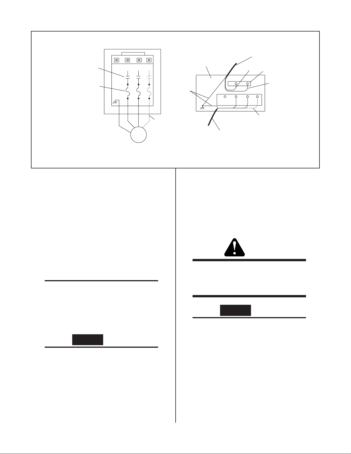
Contacts Shown
For Reference
Front View
2 1-L1 L2 L3
Top Of Starter Relay
(Box Removed)
115 VAC Single-Phase
Starter Cable
Black
Starter Coil
Heater Coils
T1 T2 T3
Motor
Figure A Electrical Connections.
STEP 4:
Replace the starter cover. Plug the starter cable into
the twist-lock receptacle marked COOLANT
RECIRCULATOR CONTROL on the torch control console or power supply.
STEP 5:
Remove the cover of the unit. Remove the temporary
yellow cap from the coolant reservoir and fill with
Thermal Arc Torch Coolant up to the level of the crosswires.
NOTE
It is helpful to make a splash guard out of the yellow cap by cutting a hole (about ½ inch in diameter) in the center of it. Place it back in the tip of
the reservoir to keep coolant from splashing out of
the unit later on when removing the air from the
system.
CAUTION
Always use Thermal Arc torch coolant. If not available use deionized water with conductivity of less
than 0.1 megohm/cm.
Install the Reservoir Cap in place of the temporary
yellow cap.
Used For
Three-Phase
Only
Green
White
2 1-L1 L2 L3
Used For
Three-Phase Only
115 VAC Single-Phase or
230/460 VAC Three-Phase
Motor Cable
STEP 6:
Connect the coolant recirculator SUPPLY and RETURN to the proper fitting (COOLANT IN and
COOLANT OUT) on the control console with two water hoses. Connect torch leads to the control console
fittings.
WARNING
Do not use pipe or metal reinforced hose for this
purpose. The fittings in the control console are
electrically hot and depend on the hose for insulation.
CAUTION
If any additional fittings or connectors are used in
the coolant system they must be made of brass or
stainless steel. Other materials will contaminate
the coolant.
STEP 7:
Check for leaks and loose hose connections. Tighten
if necessary.
Date: 10/30/98 2 Manual 0-2010
Page 3

STEP 8:
Connect primary power cable to a suitable power
source as required. Fuse the primary power for 15
amps/110 volts or 10 amps/220 volts. Close the external primary power disconnect switch. Turn the
ON/OFF switch to ON (If the unit is not equipped
with a starter, switch the coolant recirculator switch
to ON).
If the unit is three-phase, check the motor for
proper direction of rotation.
When facing the front of the unit, the fan blade
should rotate to the left. This will blow air
against the heat exchanger.
If the fan is rotating in reverse, blowing air in
the opposite direction, then exchange the primary leads connections on L2 and L3 in the
starter box.
The HE-l50 should then start.
WARNING
MAINTENANCE
1. Coolant Level
The coolant level should be maintained at the level of
the cross-wires. Always use Thermal Arc Torch Coolant (or deionized water with conductivity of less than
0.1 megohm/cm).
2. Coolant Pump
The pump will normally operate at approximately
60° C above the ambient temperature, quite hot to the
touch.
The pressure and flow through the system should be
checked periodically. The pressure may be adjusted
by removing the brass acorn nut on the pump and
turning the adjusting screw. Do not exceed 100 psi, as
this will overload the pump motor.
NOTE
The pump itself should not be disassembled, as this
voids the warranty.
3. Coolant Filter
Be sure any primary power is disconnected before
changing any connections.
STEP 9:
Run the HE-100A for several minutes with the reservoir cap removed to remove air trapped in the lines.
Turn the HE-100A off and remove the yellow cap. Add
coolant up to the level of the cross-wires inside the
reservoir neck, and install the cap/cartridge assembly supplied with the unit. Replace the cover and secure. The unit is now ready for operation.
The filter screen should be checked periodically, particularly if the pressure or flow drops off. To remove
the filter screen unscrew the large nut on the bottom
of the filter housing. The filter screen may be cleaned
or replaced.
4. Motor
The electric motor bearings should be lubricated once
a year, or approximately every two thousand hours
of operation. There are oil holes at both ends of each
motor. Add 30 drops of electric motor oil or SAE #10
lubricating oil.
5. Fan Belt
Fan belt tension should be such that moderate pressure on the belt gives about 1/2 inch deflection. The
belt tension may be adjusted by adjusting the position of the motor.
Date: 10/30/98 3 Manual 0-2010
Page 4

REPLACEMENT PARTS LIST
Parts listed are for three-phase coolant recirculator with
starter. Motor and starter for single phase unit shown
below by an asterisk.
Qty Catalog # Description
1 7-2850 Thermal Arc Coolant
1 8-1002 Replacement Filter Screen
1 8-1032 Filter
1 8-1328 Pump
1 8-1329 Fan Blade
1 8-1340 Fan Shaft
2 8-1344 Pillow Block
1 8-1346 Pulley (Pump)
1 8-1425 Pulley (For 60 Hz. Motor)
1 8-1426 Pulley (Fan)
1 8-1427 Fan Belt (50 Hz.)
1 8-1458 Pump Pulley Bushing
1 9-3618 Cap
1 9-2217 Reservoir Cap
1 9-2422 Starter
1 9-2423 Heater Coil for 460V Operation
1 9-2424 Heater Coil for 230V Operation
1 9-2469 Reservoir Assembly
1 9-2529 Fan Belt (60 Hz.)
1 9-2850 Pressure Gauge
1 9-2879 Motor
1 9-3893 Pulley (For 50 Hz. Motor)
1 9-3080 Crosswire
1 9-5022-25 Starter Cable - 25'
1 9-5022-50 Starter Cable - 50'
* 8-1327 Motor, 60 Hz.
* 9-2305 Motor, 50 Hz.
* 9-3894 Pulley, 50 Hz.
* 9-2522 Starter
* 8-1427 Fan Belt
WIRING DIAGRAMS
CR
T1
Motor
T2
CR
T1
Motor
T2
T3
CR
HE-50, HE-100 (all)
L1 L2
ON/OFF
Every effort has been made to provide complete and accurate information in this manual.
However, the publisher does not assume and
hereby disclaims any liability to any party for
any loss or damage caused by errors or omissions in this Manual, whether such errors result from negligence, accident, or any other
cause.
L1
CR
L2
3
X2
CR
L1
CR
L2
CR
L3
3
X2
Input
20 A - 115 VAC
10 A - 230 VAC
Fu
NOTE
Drawing # 42A426
Drawing # 42A425
Motor Input
(VAC, Three-Phase)
Starter Input
(VAC, Single-Phase)
Motor Input
(VAC, Three-Phase)
Starter Input
(VAC, Single-Phase)
M
Drawing # 42A430
Installation Instructions © 1981
Date: 10/30/98 4 Manual 0-2010
 Loading...