

Page 1

GAS CONTROL MODULE
Model GCM-6000 For Use With
Merlin 6000GST System
July 19, 2002
A-01791
Instruction Manual
Manual No. 0-2641
Page 2

Page 3
WARNING
WARNING
Read and understand this entire Instruction Manual and your
employer’s safety practices before installing, operating, or
servicing the equipment.
While the information contained in this manual represents our
best judgement, Thermal Dynamics Corporation assumes no
liability for its use.
Thermal Dynamics Gas Control Module, Model GCM-6000
For Use With Merlin 6000GST* System
Instruction Manual Number 0-2641
Published by:
Thermal Dynamics Corporation
82 Benning Street
West Lebanon, New Hampshire, USA 03784
(603) 298-5711
www.thermal-dynamics.com
Copyright 1997
Thermal Dynamics Corporation
All rights reserved.
Reproduction of this work, in whole or in part, without written
permission of the publisher is prohibited.
The publisher does not assume and hereby disclaims any liabil-
ity to any party for any loss or damage caused by any error or
omission in the Thermal Dynamics Gas Control Module, Model
GCM-6000, Instruction Manual, whether such error results from
negligence, accident, or any other cause.
July 19, 2002
* - Licensed under U. S. Patent No. 5,070,227
Page 4

TABLE OF CONTENTS
SECTION 1:
GENERAL INFORMATION .................................................................................................. 1
1.01 Notes, Cautions and Warnings ...................................................................... 1
1.02 Important Safety Precautions ........................................................................ 1
1.03 Publications ................................................................................................... 2
1.04 Note, Attention et Avertissement ................................................................... 3
1.05 Precautions De Securite Importantes ............................................................ 3
1.06 Documents De Reference ............................................................................. 5
1.07 Declaration of Conformity .............................................................................. 7
1.08 Statement of W arranty................................................................................... 8
SECTION 2:
INTRODUCTION & DESCRIPTION..................................................................................... 9
2.01 Scope of Manual............................................................................................ 9
2.02 General Description....................................................................................... 9
2.03 Specifications & Design Features .................................................................. 9
2.04 Options and Accessories............................................................................... 9
SECTION 3:
INST ALLATION PROCEDURES ........................................................................................ 11
3.01 Introduction.................................................................................................. 11
3.02 Site Location................................................................................................ 11
3.03 Unpacking ................................................................................................... 11
3.04 Installation - General.................................................................................... 11
3.05 Mounting Installation.................................................................................... 11
3.06 External Cable And Hose Connections........................................................ 13
3.07 Optional Secondary Gas/Water (H2O) Flow Control Module Installation ..... 14
3.08 Gas Supply Connections .............................................................................. 17
SECTION 4:
OPERATION ...................................................................................................................... 19
4.01 Introduction.................................................................................................. 19
4.02 Functional Overview .................................................................................... 19
4.03 Operating Controls & Indicators................................................................... 19
4.04 Sequence Of Operations .............................................................................. 21
SECTION 5:
CUSTOMER/OPERATOR SERVICE.................................................................................. 25
5.01 Introduction.................................................................................................. 25
5.02 Routine Maintenance................................................................................... 25
Page 5

TABLE OF CONTENTS (continued)
SECTION 6:
PAR TS LISTS.....................................................................................................................27
6.01 Introduction.................................................................................................. 27
6.02 Ordering Information.................................................................................... 27
6.03 Front P anel Replacement P arts ................................................................... 28
6.04 Lower Rear Panel Replacement Parts ......................................................... 29
6.05 Internal Control Replacement Parts............................................................. 30
6.06 Internal Fitting Replacement Parts............................................................... 31
6.07 Optional Secondary Gas/Water Flow Control Replacement Parts ............... 32
6.08 Optional Secondary Water Control Replacement P arts (Obsolete).............. 34
APPENDIX I: TIMING CHARTS OF GAS SEQUENCES ........................................................... 35
APPENDIX II: UNIT SCHEMATIC .............................................................................................. 36
APPENDIX III: GAS SOLENOID CIRCUIT DIA GRAM............................................................... 38
APPENDIX IV: PLUMBING DIA GRAM ...................................................................................... 39
MOUNTING HOLE TEMPLATE .................................................................................................. 41
Page 6

Page 7

SECTION 1:
GENERAL INFORMATION
1.01 Notes, Cautions and Warnings
Throughout this manual, notes, cautions, and warnings
are used to highlight important information. These highlights are categorized as follows:
NOTE
An operation, procedure, or backgr ound information which requires additional emphasis or is helpful in efficient operation of the system.
CAUTION
A procedure which, if not properly followed, may
cause damage to the equipment.
WARNING
A procedure which, if not properly followed, may
cause injury to the operator or others in the operating area.
1.02 Important Safety Precautions
WARNINGS
OPERATION AND MAINTENANCE OF
PLASMA ARC EQUIPMENT CAN BE DANGEROUS AND HAZARDOUS TO YOUR
HEAL TH.
Plasma arc cutting produces intense electric and
magnetic emissions that may interfere with the
proper function of cardiac pacemakers, hearing
aids, or other electronic health equipment. Persons who work near plasma arc cutting applications should consult their medical health professional and the manufacturer of the health
equipment to determine whether a hazard exists.
To prevent possible injury, read, understand and
follow all warnings, safety precautions and instructions before using the equipment. Call 1-603298-5711 or your local distributor if you have any
questions.
GASES AND FUMES
Gases and fumes produced during the plasma cutting
process can be dangerous and hazardous to your health.
• Keep all fumes and gases from the breathing area.
Keep your head out of the welding fume plume.
• Use an air-supplied respirator if ventilation is not
adequate to remove all fumes and gases.
• The kinds of fumes and gases from the plasma arc
depend on the kind of metal being used, coatings
on the metal, and the different pr ocesses. Y ou must
be very careful when cutting or welding any metals which may contain one or more of the following:
Antimony Chromium Mercury
Arsenic Cobalt Nickel
Barium Copper Selenium
Beryllium Lead Silver
Cadmium Manganese Vanadium
• Always read the Material Safety Data Sheets
(MSDS) that should be supplied with the material
you are using. These MSDSs will give you the information regarding the kind and amount of fumes
and gases that may be dangerous to your health.
• For information on how to test for fumes and gases
in your workplace, refer to item 1 in Subsection 1.03,
Publications in this manual.
• Use special equipment, such as water or down draft
cutting tables, to capture fumes and gases.
• Do not use the plasma torch in an area where combustible or explosive gases or materials are located.
• Phosgene, a toxic gas, is generated from the vapors
of chlorinated solvents and cleansers. Remove all
sources of these vapors.
• This product, when used for welding or cutting,
produces fumes or gases which contain chemicals
known to the State of California to cause birth defects and, in some cases, cancer . (California Health
& Safety Code Sec. 25249.5 et seq.)
ELECTRIC SHOCK
Electric Shock can injure or kill. The plasma arc process
uses and produces high voltage electrical energy. This
electric energy can cause severe or fatal shock to the operator or others in the workplace.
• Never touch any parts that are electrically “live”
or “hot.”
Date: No v ember 15, 2001 1 GENERAL INFORMATION
Page 8

• Wear dry gloves and clothing. Insulate yourself
from the work piece or other parts of the welding
circuit.
• Repair or replace all worn or damaged parts.
• Extra care must be taken when the workplace is
moist or damp.
• Install and maintain equipment according to NEC
code, refer to item 9 in Subsection 1.03, Publications.
• Disconnect power source before performing any
service or repairs.
• Read and follow all the instructions in the Operating Manual.
FIRE AND EXPLOSION
Fire and explosion can be caused by hot slag, sparks, or
the plasma arc.
• Be sure there is no combustible or flammable material in the workplace. Any material that cannot
be removed must be protected.
• Ventilate all flammable or explosive vapors from
the workplace.
• Do not cut or weld on containers that may have
held combustibles.
• Provide a fire watch when working in an area where
fire hazards may exist.
• Hydrogen gas may be formed and trapped under
aluminum workpieces when they are cut underwater or while using a water table. DO NOT cut
aluminum alloys underwater or on a water table
unless the hydrogen gas can be eliminated or dissipated. T rapped hydrogen gas that is ignited will
cause an explosion.
NOISE
Noise can cause permanent hearing loss. Plasma arc processes can cause noise levels to exceed safe limits. You
must protect your ears from loud noise to prevent permanent loss of hearing.
• T o protect your hearing from loud noise, wear pr otective ear plugs and/or ear muffs. Protect others
in the workplace.
• Noise levels should be measured to be sure the decibels (sound) do not exceed safe levels.
• For information on how to test for noise, see item 1
in Subsection 1.03, Publications, in this manual.
PLASMA ARC RA YS
Plasma Arc Rays can injure your eyes and burn your skin.
The plasma arc process produces very bright ultra violet
and infra red light. These arc rays will damage your
eyes and burn your skin if you are not properly pr otected.
• To protect your eyes, always wear a welding helmet or shield. Also always wear safety glasses with
side shields, goggles or other protective eye wear.
• Wear welding gloves and suitable clothing to protect your skin from the arc rays and sparks.
• Keep helmet and safety glasses in good condition.
Replace lenses when cracked, chipped or dirty.
• Protect others in the work area from the arc rays.
Use protective booths, screens or shields.
• Use the shade of lens as suggested in the following
per ANSI/ASC Z49.1:
Minimum Protective Suggested
Arc Current Shade No. Shade No.
Less Than 300* 8 9
300 - 400* 9 12
400 - 800* 10 14
* These values apply where the actual arc is clearly
seen. Experience has shown that lighter filters
may be used when the arc is hidden by the workpiece.
1.03 Publications
Refer to the following standards or their latest revisions
for more information:
1. OSHA, SAFETY AND HEAL TH STANDARDS, 29CFR
1910, obtainable from the Superintendent of Documents, U.S. Government Printing Office, Washington,
D.C. 20402
2. ANSI Standard Z49.1, SAFETY IN WELDING AND
CUTTING, obtainable from the American Welding Society, 550 N.W. LeJeune Rd, Miami, FL 33126
3. NIOSH, SAFETY AND HEALTH IN ARC WELDING
AND GAS WELDING AND CUTTING, obtainable
from the Superintendent of Documents, U.S. Government Printing Office, Washington, D.C. 20402
4. ANSI Standard Z87.1, SAFE PRACTICES FOR OCCUP ATION AND EDUCA TIONAL EYE AND F ACE PROTECTION, obtainable from American National Standards Institute, 1430 Broadway, New York, NY 10018
5. ANSI Standard Z41.1, STANDARD FOR MEN’S
SAFETY -TOE FOOTWEAR, obtainable from the American National Standards Institute, 1430 Broadway, New
York, NY 10018
GENERAL INFORMATION 2 Date: Nov ember 15, 2001
Page 9
6. ANSI Standard Z49.2, FIRE PREVENTION IN THE USE
OF CUTTING AND WELDING PROCESSES, obtainable from American National Standards Institute, 1430
Broadway, New York, NY 10018
7. AWS Standar d A6.0, WELDING AND CUTTING CONTAINERS WHICH HAVE HELD COMBUSTIBLES, obtainable from American Welding Society, 550 N.W.
LeJeune Rd, Miami, FL 33126
8. NFPA Standard 51, OXYGEN-FUEL GAS SYSTEMS
FOR WELDING, CUTTING AND ALLIED PROCESSES, obtainable from the National Fire Protection
Association, Batterymarch Park, Quincy, MA 02269
9. NFPA Standard 70, NATIONAL ELECTRICAL CODE,
obtainable from the National Fire Protection Association, Batterymarch Park, Quincy, MA 02269
10. NFPA Standar d 51B, CUTTING AND WELDING PROCESSES, obtainable from the National Fire Protection
Association, Batterymarch Park, Quincy, MA 02269
11. CGA Pamphlet P-1, SAFE HANDLING OF COMPRESSED GASES IN CYLINDERS, obtainable from the
Compressed Gas Association, 1235 Jefferson Davis
Highway, Suite 501, Arlington, VA 22202
12. CSA Standard W1 17.2, CODE FOR SAFETY IN WELDING AND CUTTING, obtainable from the Canadian
Standards Association, Standards Sales, 178 Rexdale
Boulevard, Rexdale, Ontario, Canada M9W 1R3
13. NWSA booklet, WELDING SAFETY BIBLIOGRAPHY
obtainable from the National Welding Supply Association, 1900 Arch Street, Philadelphia, PA 19103
14. American Welding Society Standard A WSF4.1, RECOMMENDED SAFE PRACTICES FOR THE PREPARATION FOR WELDING AND CUTTING OF CONT AINERS AND PIPING THAT HAVE HELD HAZARDOUS
SUBSTANCES, obtainable fr om the American Welding
Society, 550 N.W. LeJeune Rd, Miami, FL 33126
ATTENTION
Toute procédur e pouvant r ésulter
l’endommagement du matériel en cas de nonrespect de la procédur e en question.
AVERTISSEMENT
Toute procédure pouvant provoquer des blessures
de l’opérateur ou des autres personnes se trouvant
dans la zone de travail en cas de non-respect de la
procédure en question.
1.05 Precautions De Securite Importantes
AVERTISSEMENTS
L’OPÉRATION ET LA MAINTENANCE DU
MATÉRIEL DE SOUDAGE À L’ARC AU JET
DE PLASMA PEUVENT PRÉSENTER DES
RISQUES ET DES DANGERS DE SANTÉ.
Coupant à l’arc au jet de plasma produit de l’énergie
électrique haute tension et des émissions
magnétique qui peuvent interférer la fonction
propre d’un “pacemaker” cardiaque, les appareils
auditif, ou autre matériel de santé electronique.
Ceux qui travail près d’une application à l’arc au
jet de plasma devrait consulter leur membre
professionel de médication et le manufacturier de
matériel de santé pour déterminer s’il existe des
risques de santé.
15. ANSI Standard Z88.2, PRACTICE FOR RESPIRATOR Y
PROTECTION, obtainable from American National
Standards Institute, 1430 Broadway, New York, NY
10018
1.04 Note, Attention et
Avertissement
Dans ce manuel, les mots “note,” “attention,” et
“avertissement” sont utilisés pour mettre en relief des
informations à caractère important. Ces mises en relief
sont classifiées comme suit :
NOTE
Toute opération, procédure ou renseignement
général sur lequel il importe d’insister davantage
ou qui contribue à l’efficacité de fonctionnement
du système.
Date: No v ember 15, 2001 3 GENERAL INFORMATION
Il faut communiquer aux opérateurs et au personnel TOUS les dangers possibles. Afin d’éviter les
blessures possibles, lisez, comprenez et suivez tous
les avertissements, toutes les précautions de sécurité
et toutes les consignes avant d’utiliser le matériel.
Composez le + 603-298-5711 ou votr e distributeur
local si vous avez des questions.
FUMÉE et GAZ
La fumée et les gaz produits par le procédé de jet de
plasma peuvent présenter des risques et des dangers de
santé.
Page 10
• Eloignez toute fumée et gaz de votre zone de respiration. Gardez votre tête hors de la plume de fumée
provenant du chalumeau.
• Utilisez un appareil respiratoire à alimentation en air
si l’aération fournie ne permet pas d’éliminer la fumée
et les gaz.
• Ne touchez jamais une pièce “sous tension” ou “vive”;
portez des gants et des vêtements secs. Isolez-vous
de la pièce de travail ou des autres parties du circuit
de soudage.
• Réparez ou remplacez toute pièce usée ou
endommagée.
• Les sortes de gaz et de fumée provenant de l’arc de
plasma dépendent du genre de métal utilisé, des
revêtements se trouvant sur le métal et des différ ents
procédés. Vous devez prendre soin lorsque vous
coupez ou soudez tout métal pouvant contenir un ou
plusieurs des éléments suivants:
antimoine cadmium mercure
argent chrome nickel
arsenic cobalt plomb
baryum cuivre sélénium
béryllium manganèse vanadium
• Lisez toujours les fiches de données sur la sécurité
des matières (sigle américain “MSDS”); celles-ci
devraient être fournies avec le matériel que vous
utilisez. Les MSDS contiennent des renseignements
quant à la quantité et la nature de la fumée et des gaz
pouvant poser des dangers de santé.
• Pour des informations sur la manière de tester la
fumée et les gaz de votre lieu de travail, consultez
l’article 1 et les documents cités à la page 5.
• Utilisez un équipement spécial tel que des tables de
coupe à débit d’eau ou à courant descendant pour
capter la fumée et les gaz.
• N’utilisez pas le chalumeau au jet de plasma dans une
zone où se trouvent des matières ou des gaz combustibles ou explosifs.
• Le phosgène, un gaz toxique, est généré par la fumée
provenant des solvants et des produits de nettoyage
chlorés. Eliminez toute source de telle fumée.
• Ce produit, dans le procéder de soudage et de coupe,
produit de la fumée ou des gaz pouvant contenir des
éléments reconnu dans L’état de la Californie, qui
peuvent causer des défauts de naissance et le cancer .
(La sécurité de santé en Californie et la code sécurité
Sec. 25249.5 et seq.)
CHOC ELECTRIQUE
• Prenez des soins particuliers lorsque la zone de travail est humide ou moite.
• Montez et maintenez le matériel conformément au
Code électrique national des Etats-Unis. (V oir la page
5, article 9.)
• Débranchez l’alimentation électrique avant tout travail d’entretien ou de réparation.
• Lisez et respectez toutes les consignes du Manuel de
consignes.
INCENDIE ET EXPLOSION
Les incendies et les explosions peuvent résulter des scories
chaudes, des étincelles ou de l’arc de plasma. Le procédé
à l’arc de plasma produit du métal, des étincelles, des
scories chaudes pouvant mettre le feu aux matières combustibles ou provoquer l’explosion de fumées
inflammables.
• Soyez certain qu’aucune matière combustible ou inflammable ne se trouve sur le lieu de travail. Protégez
toute telle matière qu’il est impossible de retirer de la
zone de travail.
• Procurez une bonne aération de toutes les fumées
inflammables ou explosives.
• Ne coupez pas et ne soudez pas les conteneurs ayant
pu renfermer des matières combustibles.
• Prévoyez une veille d’incendie lors de tout travail dans
une zone présentant des dangers d’incendie.
• Le gas hydrogène peut se former ou s’accumuler sous
les pièces de travail en aluminium lorsqu’elles sont
coupées sous l’eau ou sur une table d’eau. NE PAS
couper les alliages en aluminium sous l’eau ou sur
une table d’eau à moins que le gas hydrogène peut
s’échapper ou se dissiper . Le gas hydrogène accumulé
explosera si enflammé.
Les chocs électriques peuvent blesser ou même tuer. Le
procédé au jet de plasma requiert et produit de l’éner gie
électrique haute tension. Cette énergie électrique peut
produire des chocs graves, voire mortels, pour l’opérateur
et les autres personnes sur le lieu de travail.
GENERAL INFORMATION 4 Date: Nov ember 15, 2001
Les rayons provenant de l’arc de plasma peuvent blesser
vos yeux et brûler votre peau. Le procédé à l’arc de
plasma produit une lumière infra-rouge et des rayons
RAYONS D’ARC DE PLASMA
Page 11

ultra-violets très forts. Ces rayons d’arc nuiront à vos
yeux et brûleront votre peau si vous ne vous protégez
pas correctement.
• Pour protéger vos yeux, portez toujours un casque ou
un écran de soudeur . Portez toujours des lunettes de
sécurité munies de parois latérales ou des lunettes de
protection ou une autre sorte de protection oculair e.
• Portez des gants de soudeur et un vêtement protecteur
approprié pour protéger votre peau contre les
étincelles et les rayons de l’arc.
• Maintenez votre casque et vos lunettes de protection
en bon état. Remplacez toute lentille sale ou
comportant fissure ou rognure.
• Protégez les autres personnes se trouvant sur la zone
de travail contre les rayons de l’arc en fournissant des
cabines ou des écrans de protection.
• Utilisez la nuance de lentille qui est suggèrée dans le
recommendation qui suivent ANSI/ASC Z49.1:
Nuance Minimum Nuance Suggerée
Courant Arc Protective Numéro Numéro
Moins de 300* 8 9
300 - 400* 9 12
400 - 800* 10 14
* Ces valeurs s’appliquent ou l’arc actuel est observé
clairement. L ’experience a démontrer que les filtres
moins foncés peuvent être utilisés quand l’arc est
caché par moiceau de travail.
1.06 Documents De Reference
Consultez les normes suivantes ou les révisions les plus
récentes ayant été faites à celles-ci pour de plus amples
renseignements :
1. OSHA, NORMES DE SÉCURITÉ DU TRA VAIL ET DE
PROTECTION DE LA SANTÉ, 29CFR 1910,
disponible auprès du Superintendent of Documents,
U.S. Government Printing Office, Washington, D.C.
20402
2. Norme ANSI Z49.1, LA SÉCURITÉ DES
OPÉRATIONS DE COUPE ET DE SOUDAGE,
disponible auprès de la Société Américaine de
Soudage (American Welding Society), 550 N.W.
LeJeune Rd., Miami, FL 33126
3. NIOSH, LA SÉCURITÉ ET LA SANTÉ LORS DES
OPÉRATIONS DE COUPE ET DE SOUDAGE À
L’ARC ET AU GAZ, disponible auprès du Superintendent of Documents, U.S. Government Printing
Office, Washington, D.C. 20402
4. Norme ANSI Z87.1, PRATIQUES SURES POUR LA
PROTECTION DES YEUX ET DU VISAGE AU TRAV AIL ET DANS LES ECOLES, disponible de l’Institut
Américain des Normes Nationales (American National Standards Institute), 1430 Broadway, New York,
NY 10018
5. Norme ANSI Z41.1, NORMES POUR LES
CHAUSSURES PROTECTRICES, disponible auprès
de l’American National Standards Institute, 1430
Broadway, New York, NY 10018
BRUIT
Le bruit peut provoquer une perte permanente de l’ouïe.
Les procédés de soudage à l’arc de plasma peuvent
provoquer des niveaux sonores supérieurs aux limites
normalement acceptables. V ous dú4ez vous pr otéger les
oreilles contre les bruits forts afin d’éviter une perte
permanente de l’ouïe.
• Pour protéger votre ouïe contre les bruits forts, portez
des tampons protecteurs et/ou des protections
auriculaires. Protégez également les autres personnes
se trouvant sur le lieu de travail.
• Il faut mesurer les niveaux sonores afin d’assurer que
les décibels (le bruit) ne dépassent pas les niveaux
sûrs.
• Pour des renseignements sur la manière de tester le
bruit, consultez l’article 1, page 5.
6. Norme ANSI Z49.2, PRÉVENTION DES INCENDIES
LORS DE L ’EMPLOI DE PROCÉDÉS DE COUPE ET
DE SOUDAGE, disponible auprès de l’American National Standards Institute, 1430 Broadway, New York,
NY 10018
7. Norme A6.0 de l’Association Américaine du Soudage
(AWS), LE SOUDAGE ET LA COUPE DE
CONTENEURS A YANT RENFERMÉ DES PRODUITS
COMBUSTIBLES, disponible auprès de la American
Welding Society, 550 N.W. LeJeune Rd., Miami, FL
33126
8. Norme 51 de l’Association Américaine pour la Protection contre les Incendies (NFPA), LES SYSTEMES
À GAZ AVEC ALIMENTATION EN OXYGENE
POUR LE SOUDAGE, LA COUPE ET LES
PROCÉDÉS ASSOCIÉS, disponible auprès de la National Fire Protection Association, Batterymar ch Park,
Quincy, MA 02269
Date: No v ember 15, 2001 5 GENERAL INFORMATION
Page 12

9. Norme 70 de la NFPA, CODE ELECTRIQUE NATIONAL, disponible auprès de la National Fire Protection Association, Batterymarch Park, Quincy, MA
02269
10. Norme 51B de la NFPA, LES PROCÉDÉS DE
COUPE ET DE SOUDAGE, disponible auprès de la
National Fire Protection Association, Batterymarch
Park, Quincy, MA 02269
11. Brochure GCA P-1, LA MANIPULATION SANS
RISQUE DES GAZ COMPRIMÉS EN CYLINDRES,
disponible auprès de l’Association des Gaz
Comprimés (Compressed Gas Association), 1235
Jefferson Davis Highway, Suite 501, Arlington, VA
22202
12. Norme CSA W117.2, CODE DE SÉCURITÉ POUR
LE SOUDAGE ET LA COUPE, disponible auprès
de l’Association des Normes Canadiennes, Standards Sales, 178 Rexdale Boulevard, Rexdale,
Ontario, Canada, M9W 1R3
13.Livret NWSA, BIBLIOGRAPHIE SUR LA
SÉCURITÉ DU SOUDAGE, disponible auprès de
l’Association Nationale de Fournitures de Soudage
(National Welding Supply Association), 1900 Arch
Street, Philadelphia, PA 19103
14. Norme AWSF4.1 de l’Association Américaine de
Soudage, RECOMMANDATIONS DE PRATIQUES
SURES POUR LA PRÉPARATION À LA COUPE ET
AU SOUDAGE DE CONTENEURS ET TUYAUX
AYANT RENFERMÉ DES PRODUITS
DANGEREUX , disponible auprès de la American
Welding Society, 550 N.W. LeJeune Rd., Miami, FL
33126
15. Norme ANSI Z88.2, PRA TIQUES DE PROTECTION
RESPIRATOIRE, disponible auprès de l’American
National Standards Institute, 1430 Broadway, New
York, NY 10018
GENERAL INFORMATION 6 Date: Nov ember 15, 2001
Page 13

1.07 Declaration of Conformity
Manufacturer: Thermal Dynamics Corporation
Address: 82 Benning Street
W est Lebanon, New Hampshire 03784
USA
The equipment described in this manual conforms to all applicable aspects and regulations of the ‘Low Voltage Directive’
(European Council Directive 73/23/EEC as amended by Council Directive 93/68/EEC) and to the National legislation for
the enforcement of this Directive.
Serial numbers are unique with each individual piece of equipment and details description, parts used to manufacture a unit
and date of manufacture.
National Standard and Technical Specifications
The product is designed and manufactured to a number of standards and technical r equirements. Among them are:
* CSA (Canadian Standards Association) standard C22.2 number 60 for Arc welding equipment.
* UL (Underwriters Laboratory) rating 94VO flammability testing for all printed-circuit boar ds used.
* ISO/IEC 60974-1 (BS 638-PT10) (EN 60 974-1) (EN50192) (EN50078) applicable to plasma cutting equipment and associ-
ated accessories.
* Extensive product design verification is conducted at the manufacturing facility as part of the routine design and manufac-
turing process. This is to ensure the product is safe, when used according to instructions in this manual and related
industry standards, and performs as specified. Rigorous testing is incorporated into the manufacturing process to ensure
the manufactured product meets or exceeds all design specifications.
Thermal Dynamics has been manufacturing products for more than 30 years, and will continue to achieve excellence in our
area of manufacture.
Manufacturers responsible representative: Giorgio Bassi
Managing Director
Thermal Dynamics Europe
Via rio Fabbiani 8A
40067 Rastignano (BO)
Italy
Date: No v ember 15, 2001 7 GENERAL INFORMATION
Page 14

1.08 Statement of Warranty
LIMITED WARRANTY: Thermal Dynamics® Corporation (hereinafter “Thermal”) warrants that its products will be free of defects in
workmanship or material. Should any failure to conform to this warranty appear within the time period applicable to the Thermal
products as stated below , Thermal shall, upon notification thereof and substantiation that the product has been stor ed, installed, operated,
and maintained in accordance with Thermal’s specifications, instructions, recommendations and recognized standard industry practice,
and not subject to misuse, repair , neglect, alteration, or accident, corr ect such defects by suitable r epair or replacement, at Thermal’s sole
option, of any components or parts of the product determined by Thermal to be defective.
THIS WARRANTY IS EXCLUSIVE AND IS IN LIEU OF ANY WARRANTY OF MERCHANTABILITY OR FITNESS FOR A
PAR TICULAR PURPOSE.
LIMITATION OF LIABILITY: Thermal shall not under any circumstances be liable for special or consequential damages, such as, but
not limited to, damage or loss of purchased or replacement goods, or claims of customers of distributor (hereinafter “Purchaser”) for
service interruption. The remedies of the Purchaser set forth herein are exclusive and the liability of Thermal with respect to any
contract, or anything done in connection therewith such as the performance or breach thereof, or from the manufacture, sale, delivery,
resale, or use of any goods covered by or furnished by Thermal whether arising out of contract, negligence, strict tort, or under any
warranty, or otherwise, shall not, except as expressly provided herein, exceed the price of the goods upon which such liability is based.
THIS WARRANTY BECOMES INVALID IF REPLACEMENT PARTS OR ACCESSORIES ARE USED WHICH MAY IMPAIR THE
SAFETY OR PERFORMANCE OF ANY THERMAL PRODUCT.
THIS WARRANTY IS INVALID IF THE PRODUCT IS SOLD BY NON-AUTHORIZED PERSONS.
The limited warranty periods for Thermal products shall be as follows (with the exception of XL Plus Series, CutMaster Series , Cougar
and DRAG-GUN): A maximum of three (3) years from date of sale to an authorized distributor and a maximum of two (2) years from
date of sale by such distributor to the Purchaser, and with the further limitations on such two (2) year period (see chart below).
The limited warranty period for XL Plus Series and CutMaster Series shall be as follows: A maximum of four (4) years from date
of sale to an authorized distributor and a maximum of three (3) years from date of sale by such distributor to the Purchaser, and
with the further limitations on such three (3) year period (see chart below).
The limited warranty period for Cougar and DRAG-GUN shall be as follows: A maximum of two (2) years from date of sale to an
authorized distributor and a maximum of one (1) year from date of sale by such distributor to the Purchaser, and with the further
limitations on such two (2) year period (see chart below).
Parts
XL Plus & Parts Parts
PAK Units, Power Supplies CutMaster Series Cougar/Drag-Gun All Others Labor
Main Power Magnetics 3 Years 1 Y ear 2 Years 1 Year
Original Main Power Rectifier 3 Y ears 1 Year 2 Years 1 Year
Control PC Board 3 Y ears 1 Year 2 Years 1 Year
All Other Circuits And Components Including, 1 Year 1 Y ear 1 Y ear 1 Year
But Not Limited To, Starting Circuit,
Contactors, Relays, Solenoids, Pumps,
Power Switching Semi-Conductors
Consoles, Control Equipment, Heat 1 Y ear 1 Year 1 Y ear
Exchanges, And Accessory Equipment
Torch And Leads
Maximizer 300 Torch 1 Y ear 1 Year
SureLok T orches 1 Y ear 1 Year 1 Y ear
All Other Torches 180 Days 180 Days 180 Days 180 Days
Repair/Replacement Parts 90 Days 90 Days 90 Days None
Warranty repairs or replacement claims under this limited warranty must be submitted by an authorized Thermal Dynamics® repair
facility within thirty (30) days of the repair . No transportation costs of any kind will be paid under this warranty. Transportation charges
to send products to an authorized warranty repair facility shall be the responsibility of the customer. All returned goods shall be at the
customer ’s risk and expense. This warranty supersedes all previous Thermal warranties.
Effective: November 15, 2001
GENERAL INFORMATION 8 Date: Nov ember 15, 2001
Page 15
SECTION 2:
INTRODUCTION &
DESCRIPTION
2.03 Specifications & Design Features
The following applies to the Gas Control Module only.
1. System Compatiblility
2.01 Scope of Manual
This manual contains descriptions, operating instructions
and maintenance procedures for the Gas Control Module GCM6000 Accessory. Service of this equipment is restricted to properly trained personnel; unqualified personnel are strictly cautioned against attempting repairs
or adjustments not covered in this manual, at the risk of
voiding the Warranty.
Read this manual thoroughly. A complete understanding of the characteristics and capabilities of this equipment will assure the dependable operation for which it
was designed.
2.02 General Description
The Gas Control Module GCM6000 Accessory extends
the necessary system gas controls away from the Merlin
6000GST Power Supply to enable remote selection of
Plasma and Secondary Gases. The unit consists of front
panel selector switches, flow and pressure adjustments.
All connections to the unit are made at the rear panel.
The Gas Control Module was designed to be used with
the Merlin 6000GST Plasma Cutting System only
2. Front Panel Controls and Indicators
MODE Switch for RUN, PILOT SET, PLASMA SET,
or SEC SET
PLASMA Gas Section Switch for AIR, O2(Oxygen), N2
(Nitrogen), or Ar/H2 (Argon/Hydrogen)
SECONDARY Gas Selection Switch for Air, N2 (Nitrogen), OTHER, or H2O (Water)
PREFLOW, PLASMA and SECONDARY Gas Regulators and pressure gauges
PREFLOW and PLASMA Flowmeters with valves
3. Rear Panel Connections
Input and output gas connections for PREFLOW,
PLASMA and SECONDARY
Gas Control Interface Cable input and output connections
4. Dimensions (H x W x D)
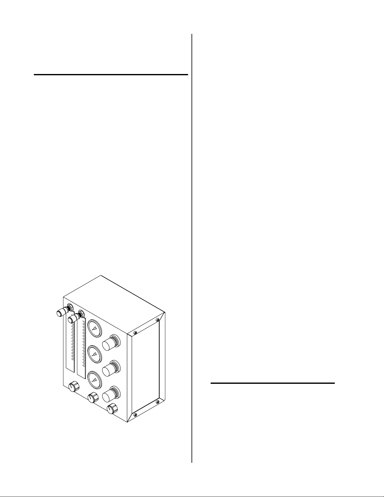
A-01791
Figure 2-1 Gas Control Module GCM6000
12 x 10 x 6 inches (305 x 254 x 152 mm)
5. Weight
16 lbs (7.26 kg)
2.04 Options and Accessories
A. Secondary Gas/Water (H20) Flow Control
An option that can be added to control the flow of gas
and water when used as the secondary . Contains control solenoids, flowmeters and control valves for accurate setting of secondary used.
NOTE
This Option must be installed on the Gas Control
Module (GCM6000) if water is to be used as the
secondary or gas flow control is required.
Manual 0-2641 9 INTRODUCTION & DESCRIPTION
Page 16

INTRODUCTION & DESCRIPTION 10 Manual 0-2641
Page 17

SECTION 3:
INSTALLATION
PROCEDURES
2. Locate the packing list(s) and use the list to identify
and account for each item.
3. Inspect each item for possible shipping damage. If
damage is evident, contact your distributor and/or
shipping company before proceeding with system
installation.
3.01 Introduction
This Section describes installation of the Gas Control and
Optional Secondary Water Control Modules. These instructions apply to these Modules only; installation procedures for the Plasma Power Supply , Arc Starter Box and
T orch are given in Manuals specifically pr ovided for those
units.
The complete installation consists of:
1. Site Selection
2. Unpacking
3. Installing Gas Control and Optional Secondary
Gas/Water Flow Control Module
4. External Cable and Hose Connections
5. Operator Training
3.02 Site Location
Select a clean, dry location with good ventilation and adequate working space around all components.
Review the safety precautions in the front of this manual
to be sure that the location meets all safety requirements.
3.03 Unpacking
Each component of the system is packaged separately and
protected with a carton and packing material to prevent
damage during shipping. Components are packaged as
follows:
A. Gas Control Components
3.04 Installation - General
WARNING
Disconnect primary power to the plasma cutting
system before installating the Gas Control.
The installation of the Gas Control Module requires
mounting the Gas Control Module and connecting all required cables and hoses.
The installation instructions are divided into Sub-Sections
for the component to be installed. The Sub-Sections are
as follows:
Section 3.05 Mounting Installation
Section 3.06 External Cable And Hose Connections
Section 3.07 Optional Secondary Gas/Water (H2O)
Flow Control Installation
Section 3.08 Gas Connections
The Gas Control Module and external cable/hose installations are the same for all systems.
3.05 Mounting Installation
The Gas Control Module must be installed in a suitable
location where it is easily accessible to the system operator . Ther e ar e four holes pr ovided in the base of the Gas
Control Module to be used for mounting the unit. The
unit must be mounted to a flat horizontal surface.
Gas Control Module components are packaged separately
and include:
• Gas Control Module
• Instruction Manual
B. Other Equipment and Accessories
Items such as Plasma Cutting Power Supply and Torch
are order ed and packaged separately from the Gas Control components.
C. Unpacking Procedure
1. Unpack each item and remove all packing material.
Manual 0-2641 11 INST ALLATION PROCEDURES
The unit must be mounted so that the Flowmeters
are plumb. If the Flowmeters are not plumb, incorrect flow indications may occur.
Install the Gas Control Module per the following procedure:
1. Remove the four screws securing the Rear Panel to
the rear of the unit.
2. Remove the Rear Panel from the unit by pulling it
straight back from the unit.
NOTE
Page 18
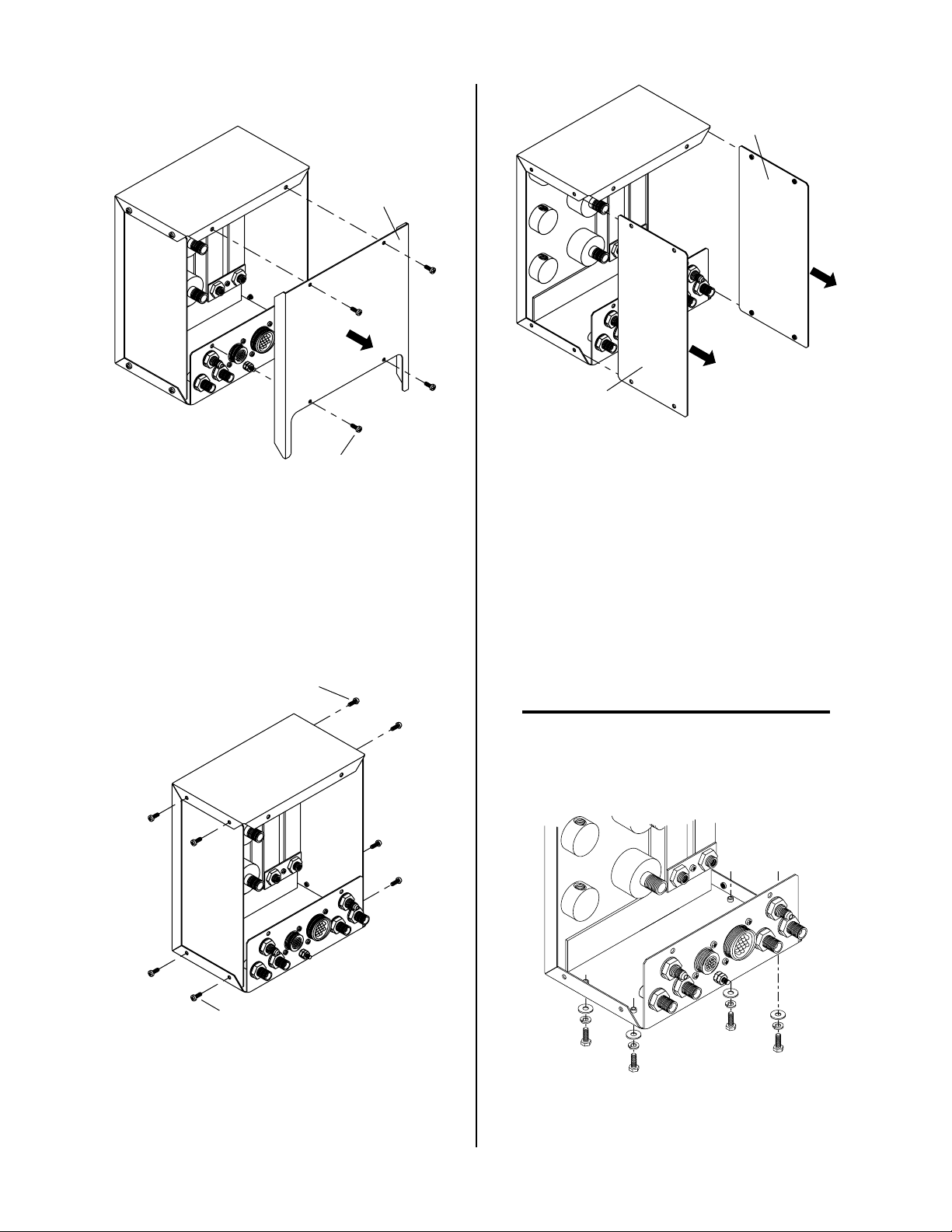
A-01794
Rear Panel
A-01803
Side Panel
(Right)
Side Panel
Figure 3-3 Side Panel Removal
(Left)
Rear Panel
Screws (4 Places)
Figure3-1 Rear Panel Removal
3. Remove the eight screws securing the Right and
Left Side Panels to the unit.
Left Side Panel
Screws (4 Places)
A-01802
5. Select a flat, horizontal, mounting surface for the
unit.
6. Using the full size template on the last page of this
Manual mark the location of the four mounting
holes.
7. Drill four 9/32 inch holes at the marked locations.
6. Mount the unit to the surface using four 1/4-20
bolts, lock washers and flat washers provided. For
convenience two different lenghts have been provided (3/4 and 1-1/2 inches).
NOTE
There are four holes provided in the base of the Gas
Control Module. Use only these four holes for
mounting the unit.
A-01804
Right Side Panel
Screws (4 Places)
1/4" Mounting Bolts,
Lock Washers and
Figure 3-2 Side Panel Screw Removal
4. Pull the two Side Panels out the back of the unit.
Figure 3-4 Mounting Hardware Installation
Flat Washers (4 Places)
INST ALLATION PROCEDURES 12 Manual 0-2641
Page 19

7. Before tighting the bolts make sure that the unit
Flowmeters are plumb.
7. Connect the Preflow Gas Hose to the internal bulkhead connection of the Master Power Supply.
8. Tighten the four bolts to secure the unit to the
mounting surface.
9. Reinstall the Side and Rear Panels (see Note).
NOTE
If the Optional Secondary Water Control is to be
installed, then continue with Section 3.07 before
reinstalling the Side and Rear Panels.
3.06 External Cable And Hose Connections
The Gas Control Module has the following connections:
• Three input gas connections
• Three output gas connections
• Control cable connections
• Grounding stud
NOTE
For proper connection of the cables and hoses to
the Power Supply and Arc Starter Box refer to the
Manuals supplied with those units.
8. Connect the other end of the hose to the 'FROM
POWER SUPPLY PREFLOW' connection at the
rear of the Gas Control Module.
A-01806
Secondary Gas Hose
(Left-Hand Thread)
J56
Plasma
Gas Hose
Rear Panel
Preflow
Gas Hose
Gas Control
Cable
1. Connect the Gas Control Cable to the rear of the
Master Power Supply 'GAS CONTROL J55' connector.
2. Connect the other end of the Gas Control Cable to
'FROM POWER SUPPL Y J56' connector at the rear
of the Gas Control Module.
NOTE
Gas hoses from the Gas Control Module to the Arc
Starter Box are marked on both ends with a blue
band. Each band is marked with 'RAS' (Remote
Arc Starter). The hoses between the Gas Control
Module and the Power Supply are not marked.
3. Connect the Plasma Gas Hose to the internal bulkhead connection of the Master Power Supply.
4. Connect the other end of the hose to the 'FROM
POWER SUPPL Y PLASMA' connection at the rear
of the Gas Control Module.
5. Connect the Secondary Gas Hose to the internal
bulkhead connection of the Master Power Supply .
6. Connect the other end of the hose to the 'FROM
POWER SUPPL Y SECONDAR Y' connection at the
rear of the Gas Control Module.
Figure 3-5 Connections From Master Power Supply
9. Connect the Arc Starter Control Cable to the 'TO
ARC STARTER BOX J57' connector at the rear of
the Gas Control Module.
10. Connect the other end of the Arc Starter Control
Cable to connector J58 at the end of the Arc Starter
Box.
11. Connect the Plasma RAS Gas Hose to the 'TO
ARC STARTER BOX PLASMA' connection at the
rear of the Gas Control Module
12. Connect the other end of the Plasma RAS Gas
Hose to the mating connector at the end of the Arc
Starter Box.
13. Connect the Secondary RAS Gas Hose to the 'TO
ARC ST ARTER BOX SECONDAR Y' connection at
the rear of the Gas Control Module
14. Connect the other end of the Secondary RAS Gas
Hose to the mating connector at the end of the Arc
Starter Box.
15. Connect the Preflow RAS Gas Hose to the 'TO
ARC ST ARTER BOX PREFLOW' connection at the
rear of the Gas Control Module
Manual 0-2641 13 INST ALLATION PROCEDURES
Page 20
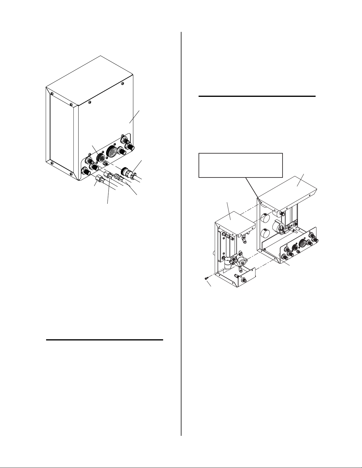
16. Connect the other end of the Preflow RAS Gas
Hose to the mating connector at the end of the Arc
Starter Box.
2. On the Optional Secondary Gas/W ater Flow Control Module remove the four screws securing the
Rear Panel. Set the Rear Panel and screws aside.
A-01805
Rear Panel
J57
Arc Starter
Control Cable
Plasma RAS Gas Hose
(Left-Hand Thread)
Secondary RAS
Gas Hose
Preflow RAS
Gas Hose
Figure 3-6 Connections From Arc Starter Box
3. Attach the Optional Secondary Gas/Water Flow
Control Module onto the right hand side of Gas
Control Module using four #10-32 x 3/8 screws
and nuts provided (see NOTE).
NOTE
The screw and nut in the upper back corner is difficult to install. To make assembly easier an optional Panel Rivet is supplied and must only be
used in the one place as shown in the following
illustration.
NOTE
May Use Supplied Optional Panel
Rivet In This Location
Optional Secondary
Gas/Water Flow
Control Module
Gas Control
Module
17. If the Optional Secondary Water (H2O) Control
was factory installed proceed with the following:
a. Connect the Secondary Water Hose to the in-
ternal bulkhead of the Master Power Supply.
b. Connect the other end of the of the Secondary
W ater Hose to the rear of the Gas Control Module.
3.07 Optional Secondary Gas/Water (H2O) Flow Control Module Installation
NOTE
This option is factory installed onto the Gas Control Module if the system was ordered with this
option.
The information in this Section is supplied for those systems that did not have the Optional Secondary Gas/W ater Flow Control Module factory installed. To install the
option use the following procedure:
1. On the Gas Control Module remove the Rear and
both Side Panels per Section 3.05.
A-02372
Nut
(4 Places)
Screw
(4 Places)
Figure 3-7 Optional Secondary Gas/Water Flow
Control Module Installation
4. At the rear of the Gas Control Module locate the
TO ARC STARTER BOX SECONDARY gas fitting.
5. Inside the Gas Control Module remove the hose
between the SECONDARY output fitting and the
gauge assembly. Push down on the connections
to release the hose. Discard this hose as it is no
longer required.
INST ALLATION PROCEDURES 14 Manual 0-2641
Page 21

A-02373
Hose
SECONDARY
Output Fitting
A-02375
Output
From Gauge
Assembly
Input T o
Flowmeter
Hose
Figure 3-10 Connecting Gas Flowmeter Input Hose
Figure 3-8 Secondary Gas Hose Removal
6. Locate the free end of the hose connected to the tee
on the output side (top) of the gas flowmeter in
the Optional Secondary Gas/Water Flow Control
Module. Connect this end to the SECONDARY
output fitting inside the Gas Contol Module.
A-02374
Hose
SECONDARY
Output Fitting
8. Inside the Gas Control Module remove the tie wrap
holding the two wires, with insulated faston terminals, to the hose.
A-02376
Wires With
Fastons
Water Solenoid
Valve
Figure 3-11 Secondary Water Solenoid Wire
Connections
Figure 3-9 Connecting Secondary Gas Ouptut Hose
9. Connect the two wires to the faston tabs on the
water solenoid valve inside the Optional Second-
7. Locate the free end of the hose connected to the
input (bottom) of the gas flowmeter in the Optional
Secondary Gas/W ater Flow Control Module. Connect this end to the output fitting at the gauge assembly inside the Gas Control Module.
ary Gas/Water Flow Control Module.
10. Connect the connector from the Optional Secondary Gas/W ater Flow Control wiring harness to the
mating connector in the wiring harness of the Gas
Control Module (see NOTE)
NOTE
If the Gas Control Module serial number ends with
the letter 'B' or earlier , then additional parts supplied with the option must be installed.
Manual 0-2641 15 INST ALLATION PROCEDURES
Page 22
If the Gas Control Module serial number ends with
the letter 'B' or earlier install additional parts per
the following:
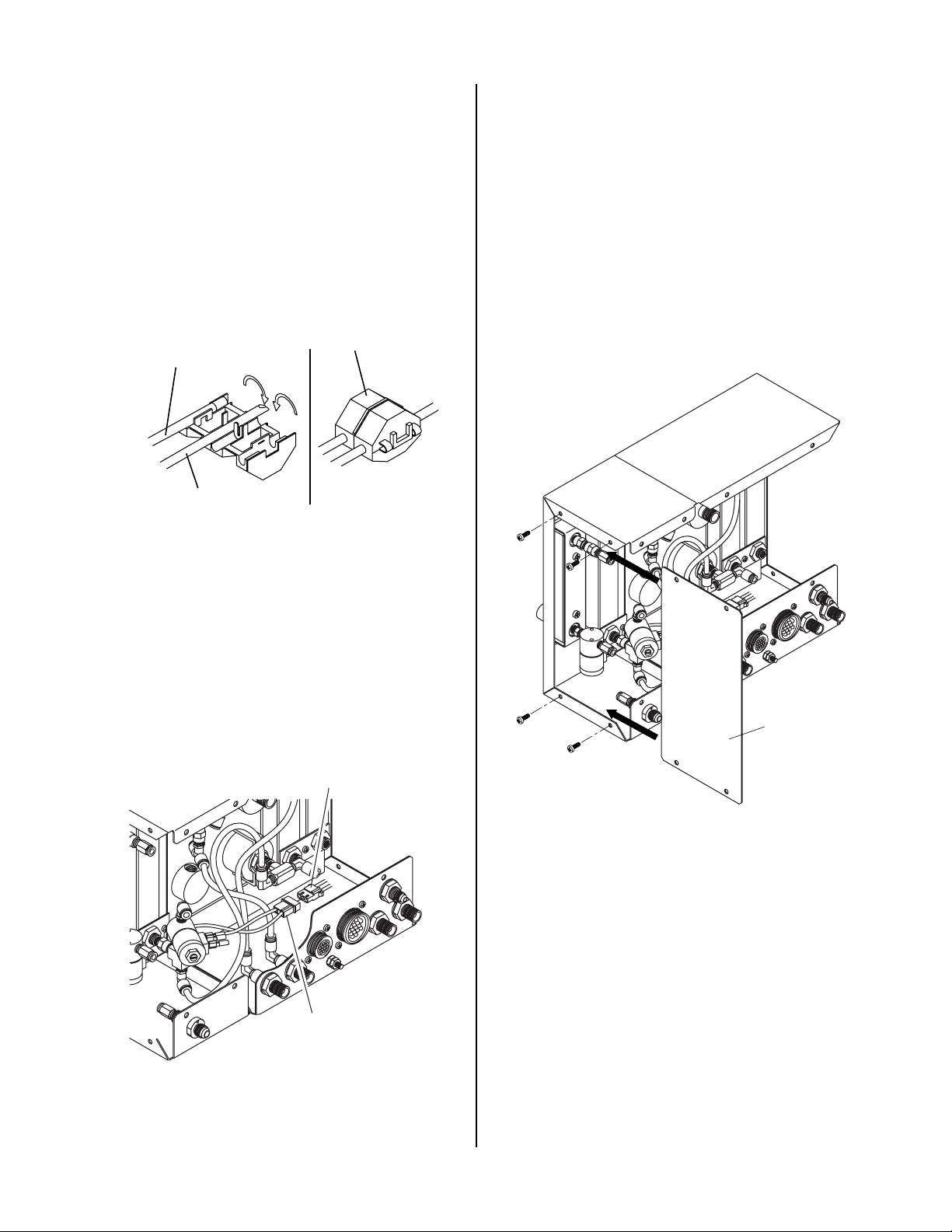
a. Locate the short wiring harness and inline splice
supplied with the option.
b. Inside the Gas Control Module locate E26 in
the lower right hand corner (viewed from the
rear of the unit) of the PC Board.
f. Remove the two nuts from the ground stud at
the rear of the Gas Control Module.
g. Pull the groud stud out of the panel and place
the wire with the ring terminal over the stud.
Insert the stud back into the panel hole and
secure with the two nuts removed above.
h. Connect wire #110 with piggy-back faston to
one of the tabs on the the W ater Solenoid V alve.
c. Place the inline splice over the wire connected
to E26.
Wire From Option
Wire Harness (Short)
Existing Wire
(From GCM Harness
at PC Board E26)
Crimp Closed
A-02383
Figure 3-12 Inline Splice Installation,
d. Place the free end of the single wire #24 from
the short wiring harness into the other slot of
the inline splice.
e. Close the inline splice making sure that it snaps
closed.
Mating Plug From
GCM Wiring Harness
11. Install the Right Side Panel from the Gas Control
Module to the right side of the Optional Secondary Gas/Water Flow Control Module.
A-02378
Right Side
Screws
(4 Places)
Panel
A-02377
Figure 3-14 Right Side Panel Installation
12. Reinstall the Left Side Panel and then the Rear
Panel to the Gas Control Module.
13. Reinstall the Rear Panel to the Optional Secondary Gas/Water Flow Control Module.
Connector From
Option Wiring Harness
Figure 3-13 Wiring Harness Connections
INST ALLATION PROCEDURES 16 Manual 0-2641
Page 23

A-02379
Secondary Gas/Water
Flow Control Rear Panel
Screws
(4 Places)
Figure 3-15 Optional Secondary Gas/Water Flow
Control Module Rear Panel Installation
14. On the Optional Secondary Gas/W ater Flow Control Module connect the water to the SECONDARY H2O fitting at the rear panel.
3.08 Gas Supply Connections
The plasma and secondary supply gases connect to fittings on the Rear Panel of the Master Power Supply.
NOTE
Refer to the Operating Manual supplied with the
Power Supply for making proper gas supply connections for the application.
A-02380
SECONDARY H20
Fitting
Water Supply
Hose
Figure 3-16 Secondary Water Connection
Manual 0-2641 17 INST ALLATION PROCEDURES
Page 24

INST ALLATION PROCEDURES 18 Manual 0-2641
Page 25
SECTION 4:
OPERATION
4.01 Introduction
1. MODE Selection Switch
The switch selects one of four setup and operation
modes:
• RUN
• PILOT SET
This Section provides a description of the Gas Control
Module.
4.02 Functional Overview
The Gas Control Module GCM 6000 provides all Plasma
and Secondary gas selection and control instrumentation
remote from the system power supply.
The Gas Control Module extends the necessary system
gas controls away from the power supply and is a required accessory with Merlin 6000GST Cutting Systems.
There are various Front Panel contr ols and indicators used
to set gas pressures and flows. The Rear Panel has connections for the gas control cable and preflow, plasma,
and secondary gas to be used.
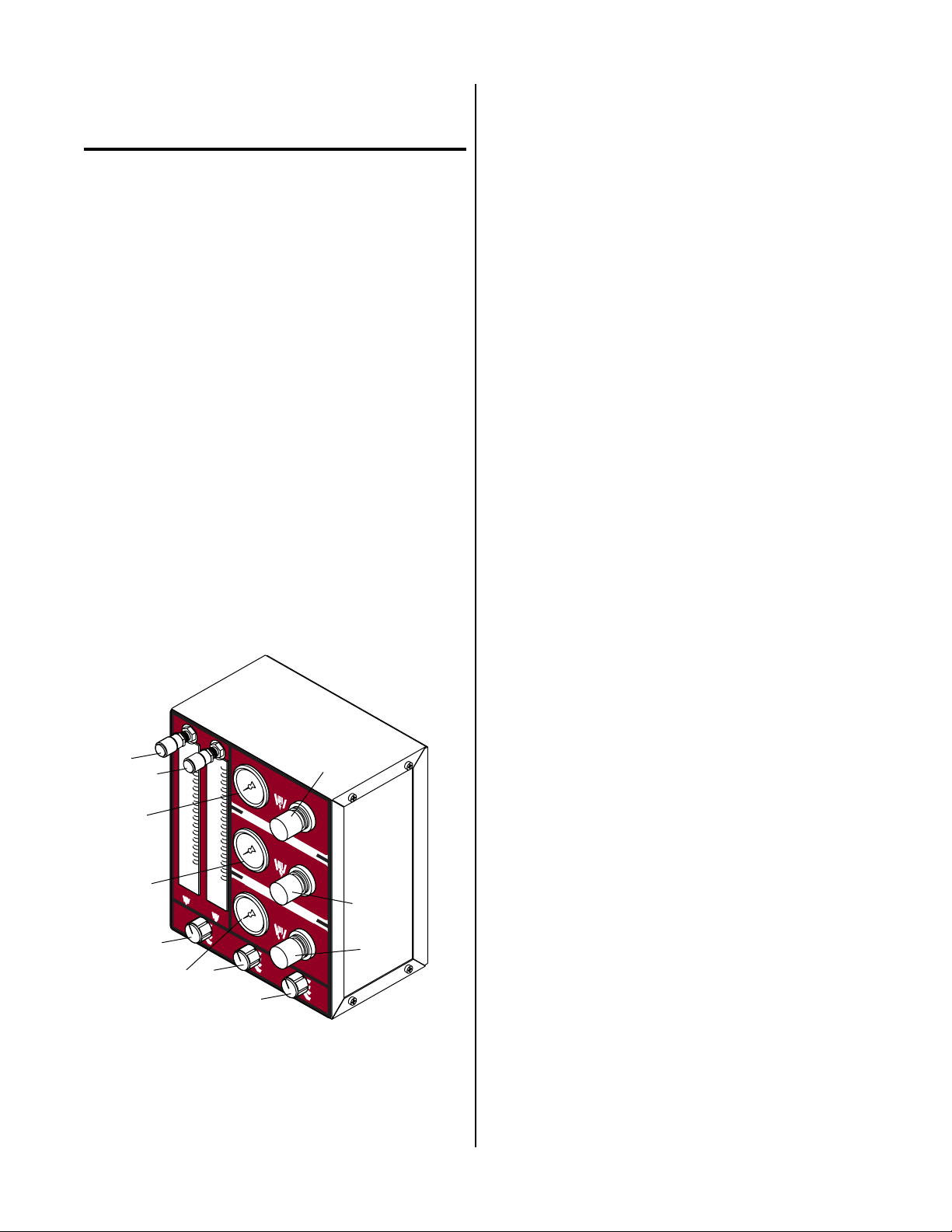
4.03 Operating Controls & Indicators
A. Front Panel
• PLASMA SET
• SEC SET (Secondary)
2. PLASMA Gas Selection Switch
The switch selects one of four plasma gases for the
operation.
• AIR
• O
(Oxygen)
2
• N2 (Nitrogen)
• Ar/H2 (Argon/Hydrogen)
3. SECONDARY Gas Selection Switch
The switch selects one of four secondary gases for the
operation.
• AIR
• N2 (Nitrogen)
• OTHER
• H2O (Water)
4
11
5
9
PREFLO
W
PLASMA
M
ODE
RUN
PILOT SET
1
PLASMA SET
SEC SET
2
7
PREFLO
GCM 6000
PLASM
Gas Contr
SECOND
PLASMA SECOND
AIR
O
2
N
2
Ar/H
2
3
W
A
ol Module
ARY
ARY
10
8
6
AIR
N
2
OTHER
H
0
2
A-01793
Figure 4-1 Front Panel Operating Controls
4. PREFLOW Gas Flowmeter
Flowmeter used to adjust the flow of the preflow gas
to the system.
5. PLASMA Gas Flowmeter
Flowmeter used to adjust the flow of the plasma gas
to the system.
6. SECONDARY Gas Regulator
Adjusts secondary gas pressure. Pull knob out and
turn clockwise to increase secondary pressure to desired level.
7. SECONDARY Gas Pressure Gauge
Indicates secondary gas pressure from 0 - 160 psi (0 11 bar).
8. PLASMA Gas Regulator
Adjusts plasma gas pressure. Pull knob out and turn
clockwise to increase secondary pressure to desired
level.
Manual 0-2641 19 OPERA TION
Page 26
9. PLASMA Gas Pressure Gauge
4. TO ARC STARTER BOX J57
Indicates plasma gas pressure from 0 - 160 psi (0 - 11
bar).
10. PREFLOW Gas Regulator
Adjusts preflow gas pressur e. Pull knob out and turn
clockwise to increase secondary pressure to desired
level.
11. PRELOW Gas Pressure Gauge
Indicates preflow gas pressure fr om 0 - 160 psi (0 -1 19
bar).
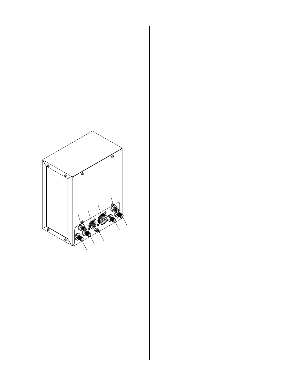
B. Rear Panel
The Gas Control Module GCM6000 rear panel includes
connections for the following interface cables and hoses.
9
6
4
3
Connector for the Arc Starter Contr ol Cable between
the Gas Control Module and the Ar c Starter Box.
5. Ground Stud
Connection used to attach a grounding wire to the
Gas Control Module.
6. FROM POWER SUPPLY J56
Connector for the Gas Control Cable between the Master Power Supply and the Gas Control Module.
7. FROM POWER SUPPLY PLASMA
Connector for the Plasma Gas Hose between the Master Power Supply and the Gas Control Module.
8. FROM POWER SUPPLY SECONDARY
Connector for the Secondary Gas Hose between the
Master Power Supply and the Gas Control Module.
9. FROM POWER SUPPLY PREFLOW
Connector for the Preflow Gas Hose between the Master Power Supply and the Gas Control Module.
C. Optional Secondary Gas/Water Flow
Control
The Optional Secondary Gas/Water Flow Control must
be installed if the following applications are to be used
on Merlin 6000GST System:
• Use water as the secondary
7
A-01792
1
5
2
Figure 4-2 Rear Panel Connections
1. TO ARC STARTER BOX PLASMA
Connector for the Plasma RAS Gas Hose between the
Gas Control Module and the Ar c Starter Box.
2. TO ARC STARTER BOX SECONDARY
Connector for the Secondary RAS Gas Hose between
the Gas Control Module and the Ar c Starter Box.
3. TO ARC STARTER BOX PREFLOW
Connector for the Preflow RAS Gas Hose between the
Gas Control Module and the Ar c Starter Box.
8
• Use 'Square Cut' 50 amp parts
1. SECONDARY H2O Flowmeter Regulator and Gauge
Flowmeter used to adjust the flow of the secondary
water to the system.
2. SECONDARY H2O (Water) Connection
Connector for the Secondary W ater Hose between the
Master Power Supply and the Gas Control Module.
3. GAS LOW-FLOW and HIGH-FLOW Switch
Switch used to select either LOW-FLOW or HIGHFLOW of the secondary gas. When using Square Cut
parts the switch must be in the LOW-FLOW position.
All other applications use HIGH-FLOW position.
4. Secondary Gas Flowmeter Regulator and Gauge
Flowmeter used to adjust the flow of the secondary
gas to the system.
OPERA TION 20 Manual 0-2641
Page 27

A-02381
NOTE
While nothing prevents the operator from switching gases during piloting or cutting it is not recommended to do so. It may cause pressure or flow
fluctuations that may damage torch parts or the
piece being cut.
4
3
1
2
Figure 4-3 Optional Secondary Gas/Water Flow
Control
4.04 Sequence Of Operations
This Subsection contains four Sequence Of Operations
that can be performed using the Gas Control Module with
or without the Optional Secondary Gas/W ater Flow Control. The Sequence of Operations are listed in seperate
paragraphs as follows:
A. Operations Without Optional Gas/Water Flow
Control
B. Operations With Optional Gas/W ater Flow Con-
trol, using CONVENTIONAL PLASMA process
(i.e. non-Square Cut)
4. Refer to the Operating Manual supplied with the Power
Supply and turn ON power to the Power Supply.
5. Select the desired plasma and secondary gases by setting the Gas Control Module front panel switches to
the desired gas positions.
6. To set the preflow gas pressure and flow rate do the
following (see NOTE):
NOTE
Preflow is set only when using oxygen (O2) plasma
gas. For all other plasma gases DO NOT do this
step.
a. Set the MODE switch to PILOT SET.
b. Fully open the valve on the top of the PREFLOW
flowmeter.
c. Pull out the knob on the PREFLOW regulator.
d. Turn the knob clockwise to increase or counter-
clockwise to decrease gas pressure.
e. Push the knob back in to lock the pressure setting.
f. Slowly close the valve on the top of the PREFLOW
flowmeter until the desired flow rate is achieved.
7. To set the plasma gas pressure and flow rate do the
following:
C. Operations With Optional Gas/Water Flow Con-
trol Using Gas Secondary Flow Control.
D. Operations With Optional Gas/W ater Flow Con-
trol Using Secondary Water
Depending on the application and the equipment installed refer to the desired Sequence of Operation.
A. Operations Without Optional Gas/Water
Flow Control
a. Set the MODE switch to PLASMA SET.
b. Fully open the valve on the top of the PLASMA
flowmeter.
c. Pull out the knob on the PLASMA r egulator.
d. Turn the knob clockwise to increase or counter-
clockwise to decrease gas pressure.
e. Push the knob back in to lock the pressure setting.
f. Slowly close the valve on the top of the PLASMA
1. Connect the required gas supplies to the correct plasma
flowmeter until the desired flow rate is achieved.
and secondary inlets on the Master Power Supply.
Refer to the Master Power Supply Operating Manual,
0-2652, to make connections.
2. Turn ON the gas supplies.
3. Set the gas bottle regulators, if used, to the proper pr essure and check for leaks.
8. To set the secondary gas pressure do the following:
a. Set the MODE switch to SEC SET.
b. Pull out the knob on the SECONDARY regulator.
c. T urn the knob clockwise to increase or counterclock-
wise to decrease gas pressure.
d. Push the knob back in to lock the pressure setting.
Manual 0-2641 21 OPERA TION
Page 28

9. Place the MODE switch to the RUN position.
NOTE
NOTE
When switching gases between operations, allow
enough purge time to clear the old gas from the
torch leads. Pilot, plasma and secondary gases are
purged separately by switching to PILOT SET,
PLASMA SET and SEC SET.
B. Operations With Optional Gas/Water Flow
Control, using CONVENTIONAL PLASMA
process (i.e. non-Square Cut)
1. Set GAS switch on the Optional Secondary Gas/Water Flow Control to the HIGH-FLOW position
2. Perform all other steps as shown above in Section
4.04-A.
C. Operations With Optional Gas/Water Flow
Control Using Gas Secondary Flow
Control.
NOTE
Gas Secondary Flow Control is used only for the
Square Cut Process using oxygen (O2) gas as the
plasma and secondary.
1. Connect the required gas supplies (or water for secondary water) to the correct plasma and secondary
inlets on the Master Power Supply. Connect the oxygen (O2) secondary gas to the OTHER secondary inlet
connection for this application Refer to the Master
Power Supply Operating Manual, 0-2652, to make
connections.
Preflow is set only when using oxygen (O
gas. For all other plasma gases DO NOT do this
step.
a. Set the MODE switch to PILOT SET.
b. Fully open the valve on the top of the PREFLOW
flowmeter.
c. Pull out the knob on the PREFLOW regulator.
d. Turn the knob clockwise to increase or counter-
clockwise to decrease gas pressure.
e. Push the knob back in to lock the pressure setting.
f. Slowly close the valve on the top of the PREFLOW
flowmeter until the desired flow rate is achieved.
7. To set the plasma gas pressure and flow rate do the
following:
a. Set the MODE switch to PLASMA SET.
b. Fully open the valve on the top of the PLASMA
flowmeter.
c. Pull out the knob on the PLASMA r egulator.
d. Turn the knob clockwise to increase or counter-
clockwise to decrease gas pressure.
e. Push the knob back in to lock the pressure setting.
f. Slowly close the valve on the top of the PLASMA
flowmeter until the desired flow rate is achieved.
8. To set the secondary gas pressure do the following:
) plasma
2
2. Turn ON the gas supplies.
3. Set the gas bottle regulators, if used, to the proper pressure and check for leaks.
NOTE
While nothing prevents the operator from switching gases during piloting or cutting it is not recommended to do so. It may cause pressure or flow
fluctuations that may damage torch parts or the
piece being cut.
4. Refer to the Operating Manual supplied with the Power
Supply and turn ON power to the Power Supply.
5. Select the desired oxygen (O2) plasma and oxygen (O2)
secondary gases by setting the Gas Control Module
front panel switches to the desired(O2 Plasma and
OTHER Secondary) gas positions.
6. To set the preflow gas pressure and flow rate do the
following (see NOTE):
a. Set the Optional Secondary Gas Flow Control
GAS switch to the LOW-FLOW position.
b. Set secondary gas selector switch to OTHER
c. Set the MODE switch to SECSET
d. Fully open the valve on the top of the secondary
flowmeter
e. Pull out the knob on the SECONDARY regulator.
f. T urn the knob clockwise to increase or counterclock-
wise to decrease gas pressure.
g. Push the knob back in to lock the pressure setting.
h.. Slowly close the valve on the top of the secondary
flowmeter until the desired flow rate is achieved.
9. Place the MODE switch to the RUN position.
OPERA TION 22 Manual 0-2641
Page 29

NOTE
When switching gases between operations, allow
enough purge time to clear the old gas from the
torch leads. Pilot, plasma and secondary gases are
purged separately by switching to PILOT SET,
PLASMA SET and SEC SET.
D. Operations With Optional Gas/Water Flow
Control Using Secondary Water
1. Connect the required plasma gas supply and secondary water to the correct plasma and secondary inlets
on the Master Power Supply. Refer to the Master
Power Supply Operating Manual, 0-2652, to make
connections.
2. Turn ON the gas supplies.
3. Set the gas bottle regulator, if used, to the pr oper
pressure and check for leaks.
4. Connect the secondary water inlet hose to a suitable water supply connection. T urn water supply on
and check for leaks.
NOTE
While nothing prevents the operator from switching gases during piloting or cutting it is not recommended to do so. It may cause pressure or flow
fluctuations that may damage torch parts or the
piece being cut.
7. To set the plasma gas pressure and flow rate do the
following:
a. Set the MODE switch to PLASMA SET.
b. Fully open the valve on the top of the PLASMA
flowmeter.
c. Pull out the knob on the PLASMA r egulator.
d. Turn the knob clockwise to increase or counter-
clockwise to decrease gas pressure.
e. Push the knob back in to lock the pressure setting.
f. Slowly close the valve on the top of the PLASMA
flowmeter until the desired flow rate is achieved.
8. T o set the secondary water flow rate do the following:
a. Set the MODE switch to SEC SET.
b. Adjust the secondary water flowmeter to the de-
sired flow rate.
9. Place the MODE switch to the RUN position.
NOTE
When switching gases between operations, allow
enough purge time to clear the old gas from the
torch leads. Pilot, plasma and secondary gases are
purged separately by switching to PILOT SET,
PLASMA SET and SEC SET.
4. Refer to the Operating Manual supplied with the Power
Supply and turn ON power to the Power Supply.
5. Select the desired plasma gas and secondary water by
setting the Gas Control Module front panel switches
to the desired positions.
6. To set the preflow gas pressure and flow rate do the
following (see NOTE):
NOTE
Preflow is set only when using oxygen (O2) plasma
gas. For all other plasma gases DO NOT do this
step.
a. Set the MODE switch to PILOT SET.
b. Fully open the valve on the top of the PREFLOW
flowmeter.
c. Pull out the knob on the PREFLOW regulator.
d. Turn the knob clockwise to increase or counter-
clockwise to decrease gas pressure.
e. Push the knob back in to lock the pressure setting.
f. Slowly close the valve on the top of the PREFLOW
flowmeter until the desired flow rate is achieved.
Manual 0-2641 23 OPERA TION
Page 30

OPERA TION 24 Manual 0-2641
Page 31
SECTION 5:
CUSTOMER/OPERATOR
SERVICE
5.01 Introduction
This Section describes basic maintenance procedures performable by operating personnel. No other adjustments
or repairs are to be attempted by other than properly
trained personnel.
WARNINGS
Disconnect primary power at the source before disassembling any part of the cutting system.
Frequently review the Important Safety Precautions (page 1). Be sure the operator is equipped with
proper gloves, clothing, eye and ear protection.
Make sure no part of the operator’s body comes into
contact with the workpiece while the cutting system is activated.
CAUTION
Sparks from the cutting process can cause damage
to coated, painted, and other surfaces such as glass,
plastic and metal.
5.02 Routine Maintenance
The only routine maintenance required for the Gas Control components is a thorough cleaning and inspection,
with the frequency depending on the usage and the operating environment.
To clean the Gas Control, first make sure that the power
is disconnected. Blow off any accumulated dirt and dust
with compressed air . The unit should also be wiped clean.
If necessary, solvents that are r ecommended for cleaning
electrical apparatus may be used.
Manual 0-2641 25 SERVICE
Page 32

SERVICE 26 Manual 0-2641
Page 33

SECTION 6:
PARTS LISTS
6.01 Introduction
A. Parts List Breakdown
The parts list provides a breakdown of all replaceable
components. The parts lists are arranged as follows:
Section 6.03: Front Panel Replacement Parts
Section 6.04: Lower Rear Panel Replacement Parts
Section 6.05: Internal Control Replacement Parts
Section 6.06: Internal Fitting Replacement Parts
Section 6.07: Optional Secondary Gas/Water Flow
Control Replacement Parts
Section 6.08: Optional Secondary Water Control Re-
placement Parts (Obsolete)
NOTE
For external replacement Cable or Hose Assemblies
refer to the Merlin 6000GST Master Power Supply Manual 0-2652.
B. Returns
If a Thermal Dynamics product must be returned for service, contact your Thermal Dynamics distributor. Materials returned to Thermal Dynamics without proper authorization will not be accepted.
6.02 Ordering Information
Order replacement parts by catalog number and complete
description of the part or assembly, as listed in the description column of the Parts List. Also include the model
and serial number of the unit. Address all inquiries to
your authorized Thermal Dynamics distributor .
Manual 0-2641 27 P A RTS LISTS
Page 34
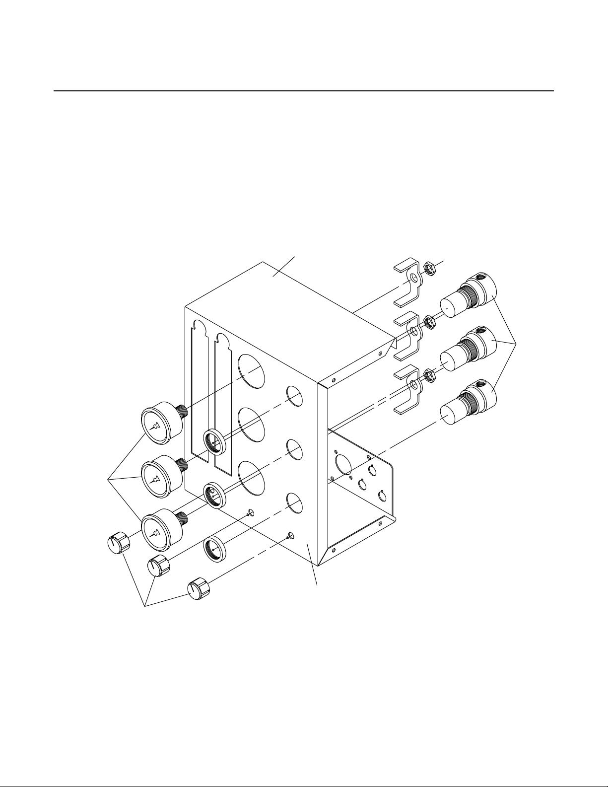
6.03 Front Panel Replacement Parts
Item # Qty Description Catalog #
1 TDC STYLE GCM-6000 GAS CONTROL MODULE
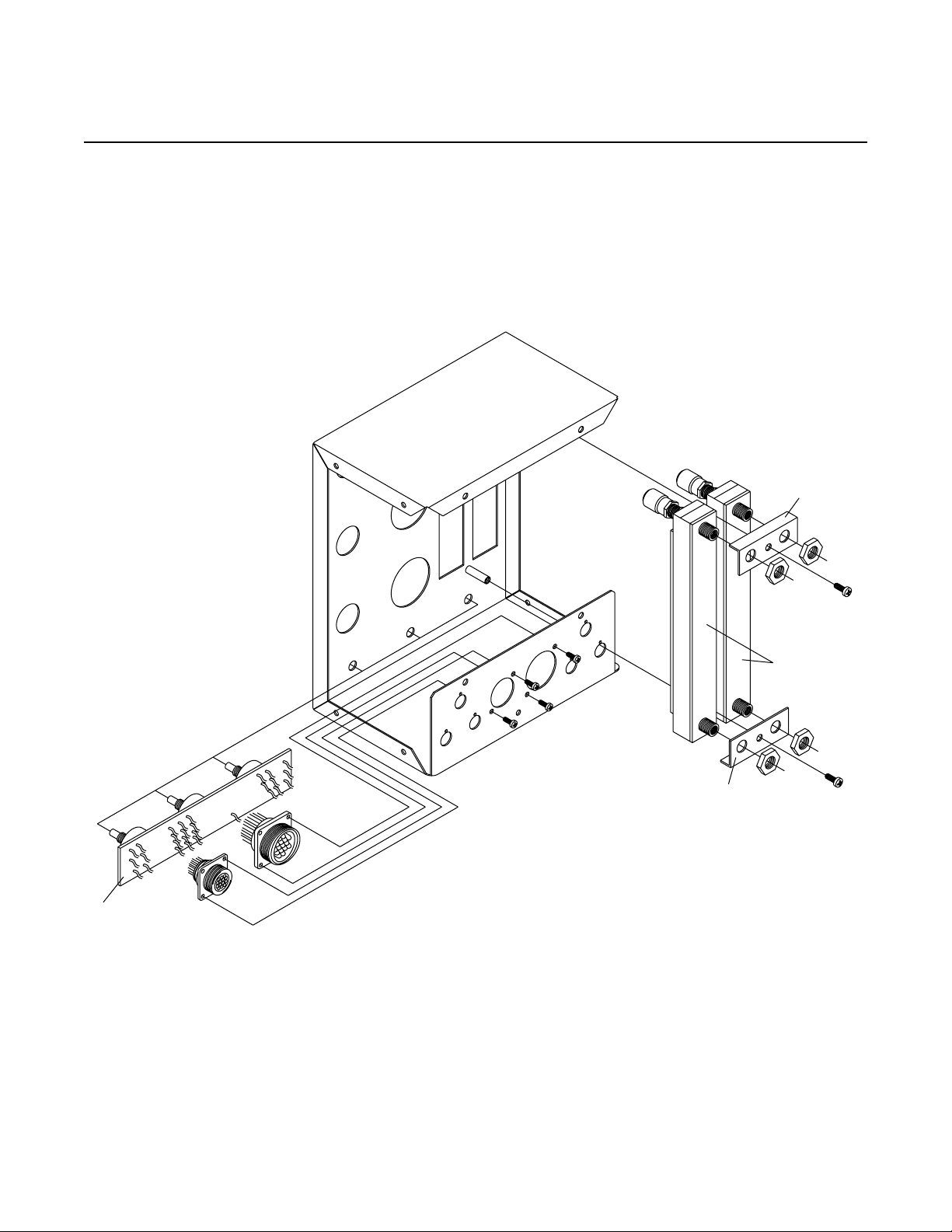
Complete Unit Without Optional Secondary Gas/Water Flow Control 3-6822
Complete Unit With Optional Secondary Gas/Water Flow Control 3-6826
1 3 1" BLACK INSTRUMENT KNOB W/LINE 9-4233
2 3 GAUGE, 0-160 PSI/BAR 2" DIA 8-6800
3 3 AIR REGULA TO R 8-3223
4 1 CHASSIS, GAS CONTROL 9-6840
5 1 OVERLAY, FRONT PANEL 9-6841
4
3
2
5
A-01795
1
PARTS LISTS 28 Manual 0-2641
Page 35
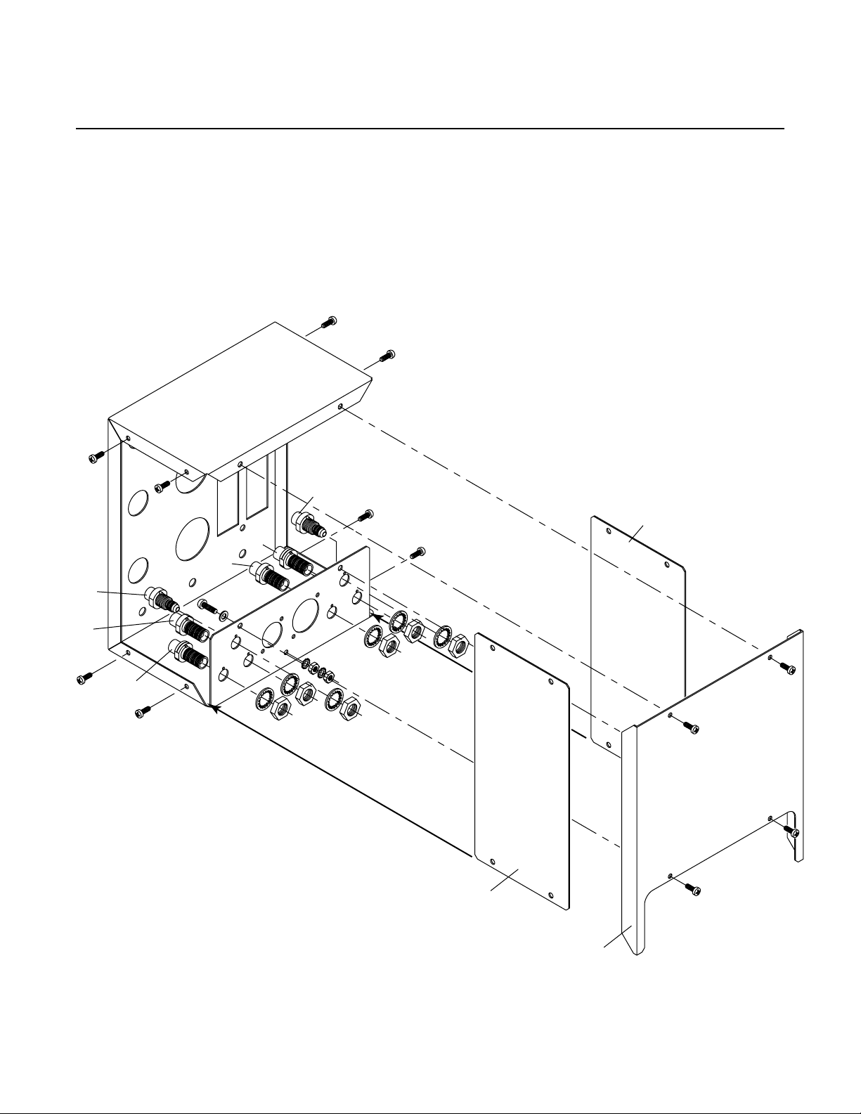
6.04 Lower Rear Panel Replacement Parts
Item # Qty Description Catalog #
1 2 BODY BULKHEAD 1/8 NPT LH 9-6842
2 2 BODY BULKHEAD 1/8 NPT 9-6843
3 2 FITTING 9/16-18 BULKHEAD #4 JICM TO 1/8 NPT-F 9-6844
4 2 PANEL,SIDE, GAS CONTROL 9-6845
5 1 COVER, GAS CONTROL 9-6846
3
4
1
2
3
2
1
A-01796
4
5
Manual 0-2641 29 P A RTS LISTS
Page 36
6.05 Internal Control Replacement Parts
Item # Qty Description Catalog #
1 1 ASS’Y, GAS CONTROL PCB 9-6847
2 2 FLOWMETER, 150MM, 0-150 REFERENCE SCALE 8-6801
3 2 BRKT , MOUNTING, FLOW METER See Note
NOTE: Item shown for illustration purposes only.
3
2
3
A-01797
1
PARTS LISTS 30 Manual 0-2641
Page 37

6.06 Internal Fitting Replacement Parts
Item # Qty Description Catalog #
Units with no letter or the letter 'A' at the end of the Serial #
1 3 1/8 NPT FEM TEE 8-0312
2 16 FITTING, 1/8 NPT X 1/4 TUBE 90° 9-7525
3 6 FITTING, 1/4 NPT X 1/4 TUBE 90° 9-6848
Units with the letter 'B' or later at the end of the Serial #
1 3 ONE TOUCH TEE FITTING 8-3288
2 10 ONE TOUCH 90 DEG 1/8 NPT 8-3289
3 6 ONE TOUCH 90 DEG 1/4 NPT 8-3290
4 3 1/8 NPT FEM COUPLING 9-2984
Units with no letter or the letter 'A' at the end of the Serial #
2
1
2
2
2
2
2
2
1
2
1
2
3
2
3
Units with the letter 'B' or later at the end of the Serial #
4
2
2
2
2
2
3
2
1
4
1
4
1
2
2
3
A-01798
Manual 0-2641 31 P A RTS LISTS
Page 38

6.07 Optional Secondary Gas/Water Flow Control Replacement Parts
NOTE
This Subsection is only for repair parts for systems that the new style Optional Secondary Gas/Water Flow Control
(Rev 'C' or later) installed. Refer to Subsection 6.08 for units Rev 'B' or earlier for parts. The Rev is the letter at the
end of the unit serial number .
Item # Qty Description Catalog #
1 Retro Kit, GCM6000 Secondary Gas/H2O Flow Control Includes: 5-6826
4 SCREW, 10-32 X 3/8 PPH STL/ZN SWAGEFORM See Note
1 ASSY, OPTIONAL SECONDARY WATER/GAS CONTROL Includes:
1 1 ASSY, SWITCH, SECONDARY GAS FLOW CONTROL 9-7007
2 3 VALVE, CHECK, 1/8NPTM, 0.5 PSI OPEN 9-7006
3 1 FLOWMETER, 150MM, 0-150 REFERENCE SCALE 8-6801
4 1 1" BLACK INSTRUMENT KNOB W/LINE 9-4233
5 3 VALVE, SOLENOID 1/8 NPT 8-3370
6 1 FLOWMETER, WATER, W/ VALVE, 100PSIG MAX, 1 - 10 GPH 9-7005
7 1 FITTING, 9/16-18 BULKHEAD, #6 JIC-M TO 1/8 NPT-F 8-8024
8 3 ONE TOUCH 90 DEG 1/8 NPT 8-3289
9 2 1/8 NPT FEM COUPLING 9-2984
10 2 1/8 NPT STR.TEE 8-0352
11 1 ONE TOUCH TEE, 1/8 NPTM X 1/4 TUBE 8-3288
12 1 9/16-18 JAM NUT, BRASS 8-2149
13 3 FITTING, 1/8 NPT X 1/4 TUBE STR 8-3360
14 2 HEX NIPPLE, 1/8 NPTM 9-5554
15 6 SCREW, 10-32 X 3/8 PPH STL/ZN SWAGEFORM See Note
16 4 #10-32 X 3/4" PHILLIPS PAN HEAD M.S., ZINC PLATED See Note
NOTE: Item may be purchased locally.
PARTS LISTS 32 Manual 0-2641
Page 39

14
5
10
8
2
3
9
11
8
To GCM
5
10
2
8
4
To GCM
1
13
12
7
2
9
13
6
14
5
13
A-02382
Manual 0-2641 33 P A RTS LISTS
Page 40

6.08 Optional Secondary Water Control Replacement Parts (Obsolete)
NOTE
This Subsection is supplied only for repair parts for systems that may have the older style Optional Secondary
Water Control (Rev 'B' or earlier) installed. Refer to Subsection 6.07 for Rev 'C' or later parts. The Rev is the letter
at the end of the unit serial number .
Item # Qty Description Catalog #
1 ASSEMBLY, OPTIONAL SECONDARY WATER CONTROL - Complete See Note
1 1 FLOWMETER, WATER, W/ VALVE, 100PSIG MAX, 1 - 10 GPH9-7005
2 1 VALVE, SOLENOID 1/8 NPT 8-3370
1
2
A-01841
PARTS LISTS 34 Manual 0-2641
Page 41
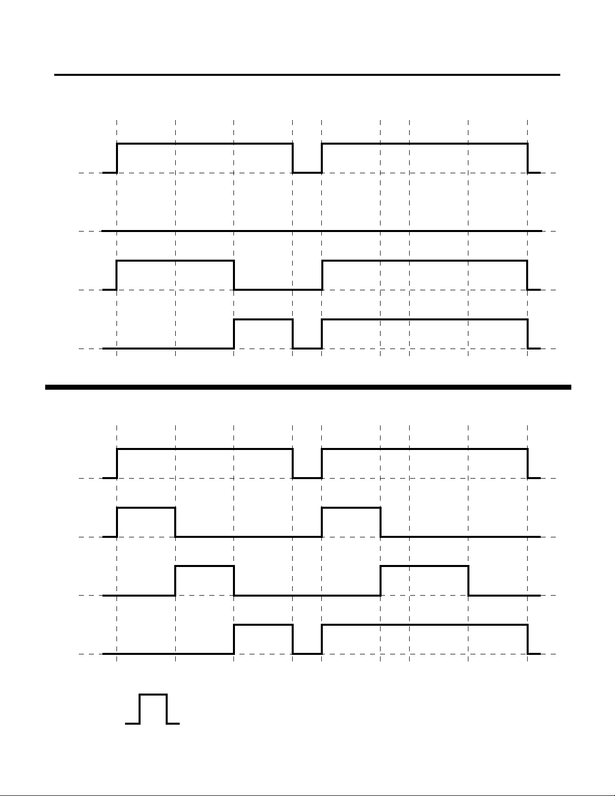
APPENDIX I: TIMING CHARTS OF GAS SEQUENCES
SOL1 Plasma
SOL2 Pre-Flow N2
SOL3 Cut-flow
SOL4 Secondary
Merlin 6000GST Gas Sequence All Gases Except O
PILOT SET PLASMA SET SEC SET
(Oxygen) Plasma
2
Start
PREFLOW CUT POSTFLOW
Transfer StopPilot
SOL1 Plasma
SOL2 Pre-Flow N2
SOL3 Cut-flow O
SOL4 Secondary
Merlin 6000GST Gas Sequence Using O2 (Oxygen) Plasma
PILOT SET PLASMA SET SEC SET
2
Solenoid ON
Start
PREFLOW CUT POSTFLOW
Transfer StopPilot
A-01801
Solenoid OFF
Manual 0-2641 35 APPENDIX
Page 42

APPENDIX II: UNIT SCHEMATIC
A-01800
APPENDIX 36 Manual 0-2641
Page 43

A-01800
Manual 0-2641 37 APPENDIX
Page 44
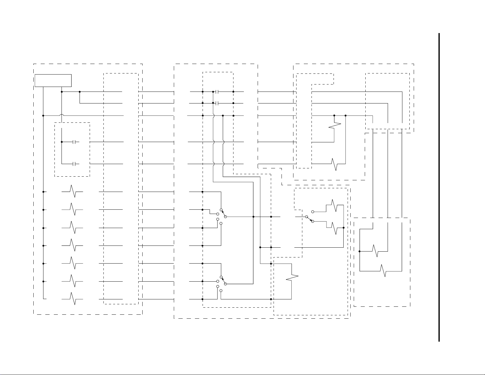
APPENDIX 38 Manual 0-2641
APPENDIX III: GAS SOLENOID CIRCUIT DIAGRAM
Merlin 6000GST Power Supply
120 VA C
Return Supply
(24)
(110)
J2-5
K4
Plasma
K5
Secondary
Logic PC Board
Air
SOL 6
J100-1
O
SOL 7
2
J101-1
N2
SOL 8
J102-1
Ar/H2
SOL 9
J103-1
Air
SOL 10
J104-1
N2
SOL 11
J105-1
Other
SOL 12
J106-1
Gas Select Solenoids
J2-3
J2-7
J100-3
J101-3
J102-3
J103-3
J104-3
J105-3
J106-3
(50)
(75)
Gas Control
Connector
J55-15
J55-11
J55-1
(111)
J55-10
(112)
J55-9
(113)
J55-8
(114)
J55-7
(115)
J55-6
(116)
J55-5
(117)
J55-4
J55-3
J55-2
Gas Control
Cable
Gas Control Module GCM6000
Gas Contol
PC Board
J56-15
J56-11
J56-1
J56-3
J56-2
J56-10
J56-9
J56-8
J56-7
J56-6
J56-5
J56-4
(24)
(24)
(110)
(60)
(75)
(111)
(112)
(113)
(114)
(115)
(116)
(117)
E12
E26
E1
E14
E15
E16
E17
E10
E9
E8
K2
E20
E19
K1
E4
SW2
PLASMA
SECONDARY
(147)
(148)
(110)
SW3
J57-1
J57-2
J57-3
J57-5
J57-4
Arc Starter
Control Cable
(24)
E27
J61-3
Internal
Connector
(110)
E28
J61-1
(110)
E11
E7
(150)
Arc Starter Box
Panel Connector
J58-1
J58-2
J58-3
(147)
(148)
(110)
SOL 1
Plasma
J58-5
J58-4
(60)
(75)
SOL 4
Secondary
SW4
HI or LOW
(24)
(152)
(153)
(110)
SOL1
Secondary H
Optional Secondary
Gas/H
O Flow Control
2
SOL13
Low Flow
SOL14
High Flow
O
2
Torch Control
Cable Connector
J59-3 J59-2 J59-1
Cable Part Of
Torch Leads
J60-3 J60-2 J60-1
SOL 2
Pre-Flow
SOL 3
Cut Flow
Torch Mounted
Solenoid Assembly
A-01836
Page 45
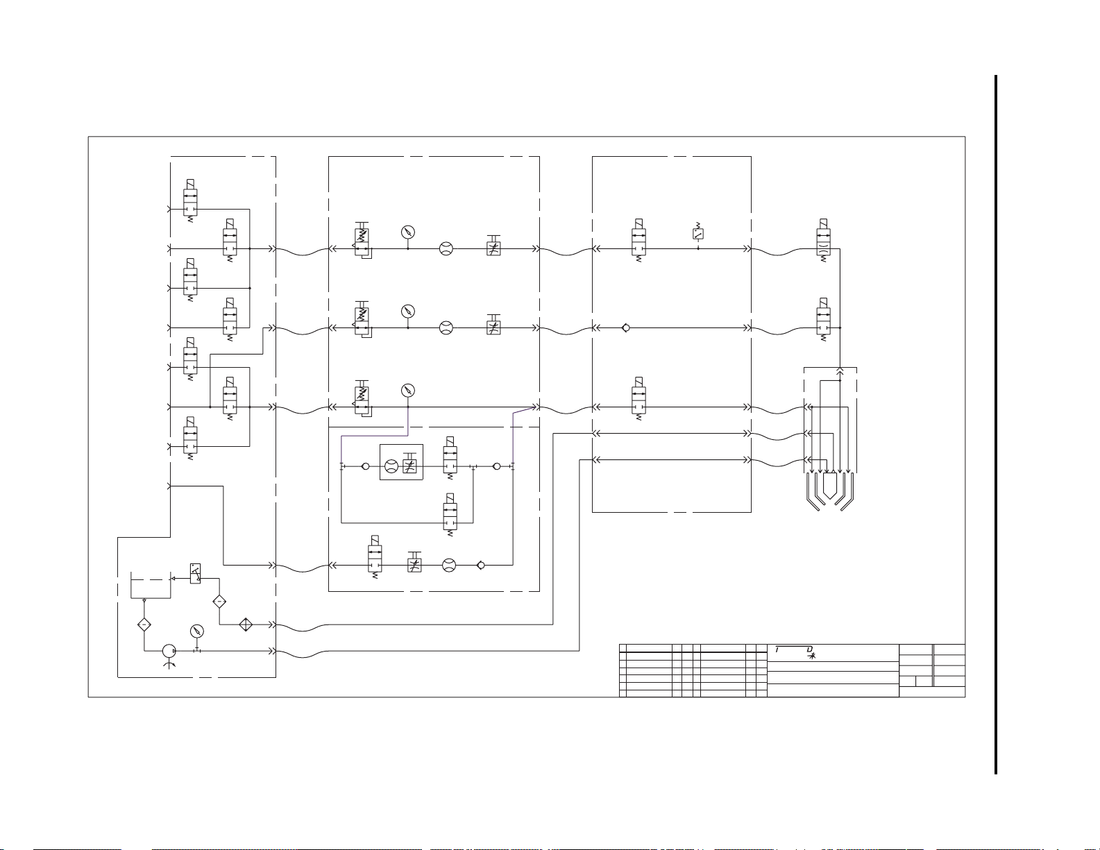
Manual 0-2641 39 APPENDIX
PLASMA
AIR
PLASMA
OXYGEN
PLASMA
NITROGEN
PLASMA
ARGON/
HYDROGEN
SECONDARY
AIR
SECONDARY
NITROGEN
SECONDARY
OTHER
SECONDARY
WATER
RESERVOIR 1
FILTER 1
PUMP 1
POWER SUPPLY ARC STARTER BOX
GAS CONTROL MODULE
SOL 6
SOL 7
PR 1
PG 1
FM 1
MV 1
SOL 1
SOL 8
SOL 9
PR 2
PG 2
FM 2
MV 2
CV 1
SOL 10
SOL 11
PR 3
PG 3
SOL 4
SOL 12
SOL 13
CV 3
FM 4
CV 4
MV 4
SOL 14
SOL 5
MV 3
FM 3
FS 1
PG 4
FILTER 2
RADIATOR 1
OPTIONAL SECONDARY FLOW CONTROL
COOLANT RETURN
COOLANT SUPPLY
CV 2
PRODUCTION RELEASE
A
REV OPTIONAL SECONDARY
FLOW CONTROL EC8119
B
PS 1
SOL 3
APPENDIX IV: PLUMBING DIAGRAM
SOL 2
TORCH
Scale
DateByREVISIONSRevDateByREVISIONSRev
09/30
FAR
'97
01/29
RWH
99
HERMAL YNAMICS
Information proprietary to Thermal Dynamics Corporation.
Not for release, reproduction, or distribution.
MATERIAL
N/A
TITLE
MERLIN 6000 GST
PLUMBING SCHEMATIC
CORPORATION
Industrial Park No.2
West Lebanon, NH 03784
(603)298-5711
Supercedes
N/A
.
Date
Superceded By
03/12/97
Reference
Drawn
FAR
.
AppChk
OF
..
42X972
A-02384
Page 46

APPENDIX 40 Manual 0-2641
Page 47

Manual 0-2641 41 APPENDIX
To Side of Gas Control Module
Rear Edge of Gas Control Module
0.5" (12.7 mm)
0.910"
(23.11 mm)
3.0"
(76.2 mm)
9.0"
(228.6 mm)
0.281" (7.14 mm)
Mounting Hole
4 Places
2.0"
(50.8 mm)
MOUNTING HOLE TEMPLATE
A-01799
Front Edge of Gas Control Module
Page 48

 Loading...