

Page 1
TWECO®
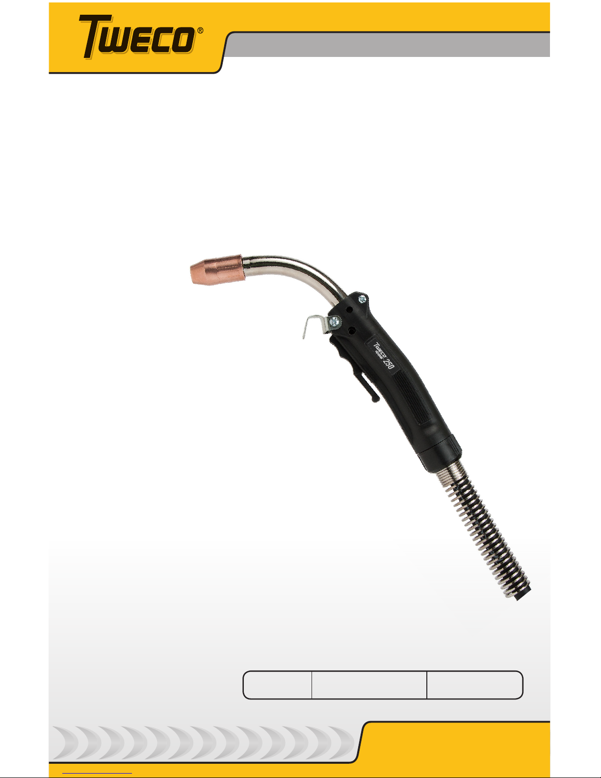
FUSION™250
Safety and
Operating
Instructions
AIR-COOLED MIG GUN 250 AMP
Tweco.com
English
Canadien Français
Americas Español
Revision: B Issue Date: August 2, 2013 Manual No.: 89200015
IMPORTANT: Included inside - special
instructions for liner replacement.
Page 2

WE APPRECIATE YOUR BUSINESS!
Congratulations on receiving your new Tweco product. We are proud to
have you as our customer and will strive to provide you with the best
service and support in the industry. This product is backed by our extensive
warranty and world-wide service network.
We know you take pride in your work and we feel privileged to provide you
with this high performance product that will help you get the job done.
For more than 75 years Tweco has provided quality products you can trust,
when your reputation is on the line.
YOU ARE IN GOOD COMPANY!
Tweco is a Global Brand of Arc Welding Products for Victor Technologies
Inc. We distinguish ourselves from our competition through marketleading innovation and truly dependable products that will stand the test of
time.
We strive to enhance your productivity, efficiency and welding performance
enabling you to excel in your craft. We design products with the welder in
mind delivering- advanced features, durability, ease of use and ergonomic
comfort.
Above all, we are committed to a safer working environment within the
welding industry. Your satisfaction with this product and its safe operation
is our ultimate concern. Please take the time to read the entire manual,
especially the Safety Precautions.
If you have any questions or concerns regarding your new Tweco product,
please contact our friendly and knowledgeable Customer Service Team at:
1-800-462-2782 (USA) and 1-905-827-4515 (Canada),
or visit us on the web at www.Tweco.com
Page 3

i
WARNINGS
Read and understand this entire Manual and your employer’s safety practices
before installing, operating, or servicing the equipment. While the information
contained in this Manual represents the Manufacturer’s judgment, the Manufacturer
assumes no liability for its use.
Tweco® Fusion 250 AMP MIG Gun
Safety and Operating Instructions
Instruction Guide Number 89200015
Published by:
Victor Technologies, Inc.
2800 Airport Rd.
Denton, TX. 76208
(940) 566-2000
www.tweco.com
U.S. Customer Care: (800) 426-1888
Canada Customer Care: 905-827-4515
International Customer Care: (940) 381-1212
Copyright © 2012, 2013 Victor Technologies, Inc. All rights reserved.
Reproduction of this work, in whole or in part, without written permission of the publisher is
prohibited.
The publisher does not assume and hereby disclaims any liability to any party for any loss
or damage caused by any error or omission in this Manual, whether such error results from
negligence, accident, or any other cause.
Publication Date: December 17, 2012
Revision Date: August 2, 2013
Record the following information for Warranty purposes:
Where Purchased:
Purchase Date:
Equipment Serial #:
Page 4

ii
Table of Contents
SECTION 1: SAFETY PRECAUTIONS .........................................................................3
1.01 Safety Precautions .......................................................................... 3
SECTION 2: INTRODUCTION ......................................................................................5
2.01 How to Use this Manual ................................................................... 5
2.02 Receipt of Equipment ....................................................................... 5
2.03 Description ....................................................................................... 5
SECTION 3: MIG GUN SPECIFICATIONS.....................................................................6
3.01 MIG Gun Classification ..................................................................... 6
3.02 Duty Cycles ..................................................................................... 6
3.03 Tweco® fusion 250A MIG Gun Selection guide ................................ 7
3.04 Tweco® Fusion 250A MIG Gun Part Number Identification .............. 7
3.05 Velocity Contact Tip Nozzle Identification .........................................8
3.06 Velocity 250 Amp Conductor Tube Identification ............................. 8
SECTION 4: MIG GUN INSTALLATION ........................................................................9
4.01 Direct Plug MIG Gun Installation ...................................................... 9
4.02 Tweco® MIG-Kwik Connection and Adapter Kit Installation ........... 10
SECTION 5: REPLACEMENT INSTRUCTIONS ...........................................................11
5.01 Replacing Velocity Contact Tip ...................................................... 11
5.02 Replace Conductor Tube ............................................................... 11
5.03 Conduit Identification and Replacement ......................................... 12
5.04 Replacing Handle, trigger .............................................................. 13
SECTION 6: CABLEHOZ® REPAIR ............................................................................14
6.01 Tools Required ............................................................................... 14
6.02 Repair of Cablehoz® ...................................................................... 14
SECTION 7: MAINTENANCE AND TROUBLESHOOTING............................................19
SECTION 8: 250 AMP REPLACEMENT PARTS .........................................................20
8.02 Tweco® Fusion 250 A MIG Gun Parts ............................................ 20
8.02 Tweco® Fusion MIG Gun Consumables ......................................... 22
SECTION 9: STATEMENT OF WARRANTY ................................................................24
9.01 Warranty Schedule .........................................................................24
Global Contact Information ...............................................Rear Cover
Page 5
SAFETY AND OPERATING INSTRUCTIONS
389200015
SECTION 1:
SAFETY PRECAUTIONS
1.01 SAFETY PRECAUTIONS
WARNING
SERIOUS INJURY OR DEATH may result if welding and cutting equipment is not
properly installed, used, and maintained. Misuse of this equipment and other
unsafe practices can be hazardous. The operator, supervisor, and helper must read
and understand the following safety warnings and instructions before installing
or using any welding or cutting equipment, and be aware of the dangers of the
welding or cutting process. Training and proper supervision are important for a
safe work place. Keep these instructions for future use. Additional recommended
safety and operating information is referenced in each section.
WARNING
WARNING: This product contains chemicals, including lead, known to the State
of California to cause birth defects and other reproductive harm. Wash hands
after handling.
ELECTRIC SHOCK CAN CAUSE INJURY OR DEATH
Install and maintain equipment in accordance with the National Electrical Code
(NFPA 70) and local codes. Do not service or repair equipment with power on.
Do not operate equipment with protective insulators or covers removed. Service
or repair to equipment must be done by qualified and/or trained personnel only.
Do not contact electrically live parts. Always wear dry welding gloves that are in
good condition. Aluminized, protective clothing can become part of the electrical
path. Keep oxygen cylinders, chains, wires, ropes, cranes, and hoists away from any part of the
electrical path. All ground connections must be checked periodically to determine if they are
mechanically strong, and electrically adequate for the required current. When engaged in AC
welding/cutting under wet conditions or where perspiration is a factor, the use of automatic
controls for reducing the no load voltage is recommended to reduce shock hazards. Accidental
contact must be prevented when using open circuit voltage exceeding 80 volts AC, or 100 volts
DC by adequate insulation or other means. When welding is to be suspended for any length of
time, such as during lunch or overnight, all electrode holders and electrodes should be removed
from the electrode holder and the power supply should be turned off to prevent accidental
contact. Keep MIG Guns, electrode holders, Tig torches, Plasma torches, and electrodes away
from moisture and water. See safety and operating references 1, 2, and 8.
SMOKE, FUMES, AND GASES CAN BE DANGEROUS TO YOUR HEALTH
Ventilation must be adequate to remove smoke, fumes, and gases during
operation to protect operators and others in the area. Vapors of chlorinated
solvents can form the toxic gas “Phosgene” when exposed to ultraviolet radiation
from an electric arc. All solvents, degreasers, and potential sources of these
vapors must be removed from the operating area. Use air-supplied respirators
if ventilation is not adequate to remove all fumes and gases. Oxygen supports, and vigorously
accelerates fire and should never be used for ventilation. See safety and operating references
1, 2, 3, and 4.
Page 6
4
SAFETY AND OPERATING INSTRUCTIONS
89200015
ARC RAYS, HOT SLAG, AND SPARKS CAN INJURE EYES AND BURN SKIN
Welding and cutting processes produce extreme localized heat and strong
ultraviolet rays. Never attempt to weld/cut without a federally compliant welding
helmet with the proper lens. A number 12 to 14 shade filter lens provides the
best protection against arc radiation. When in a confined area, prevent the
reflected arc rays from entering around the helmet. Approved shielding curtains
and appropriate goggles should be used to provide protection to others in the surrounding area.
Skin should be protected from arc rays, heat, and molten metal. Always wear protective gloves
and clothing. All pockets should be closed and cuffs sewn shut. Leather aprons, sleeves, leggings,
etc. should be worn for out-of-position welding and cutting, or for heavy operations using large
electrodes. Hightop work shoes provide adequate protection from foot burns. For added protection,
use leather spats. Flammable hair preparations should not be used when welding/cutting. Wear
ear plugs to protect ears from sparks. Where work permits, the operator should be enclosed in
an individual booth painted with a low reflective material such as zinc oxide.
See safety and operating references 1, 2, and 3.
WELDING SPARKS CAN CAUSE FIRES AND EXPLOSIONS
Combustibles reached by the arc, flame, flying sparks, hot slag, and heated
materials can cause fire and explosions. Remove combustibles from the work
area and/or provide a fire watch. Avoid oily or greasy clothing as a spark may
ignite them. Have a fire extinguisher nearby, and know how to use it. If welding/
cutting is to be done on a metal wall, partition, ceiling, or roof, precautions must
be taken to prevent ignition of nearby combustibles on the other side. Do not
weld/cut containers that have held combustibles. All hollow spaces, cavities, and containers
should be vented prior to welding/cutting to permit the escape of air or gases. Purging with inert
gas is recommended. Never use oxygen in a welding torch. Use only inert gases or inert gas
mixes as required by the process. Use of combustible compressed gases can cause explosions
resulting in personal injury or death. Arcing against any compressed gas cylinder can cause
cylinder damage or explosion. See safety and operating references 1, 2, 5, 7, and 8.
NOISE CAN DAMAGE HEARING
Noise from the air carbon-arc process can damage your hearing. Wear protective
hearing devices to ensure protection when noise levels exceed OHSA standards.
Adequate hearing protection devices must be worn by operators and surrounding
personnel to ensure personal protection against noise. See safety and operating
references 1, 2, and 6.
SAFETY AND OPERATING REFERENCES
1. Code of Federal Regulations (OSHA) Section 29, Part 1910.95, 132, 133, 134, 139,
251, 252, 253, 254 and 1000. U.S. Government Printing Office, Washington, DC 20402.
2. ANSI Z49.1 “Safety in Welding and Cutting”.
3. ANSI Z87.1 “Practice for Occupational and Educational Eye and Face Protection”.
4. ANSI Z88.2. “Standard Practice for Respiratory Protection”. American National
Standards Institute, 1430 Broadway, New York, NY 10018.
5. AWS F4.1. “Recommended Safe Practices for Welding and Cutting Containers”.
6. AWS C5.3. “Recommended Practices for Air Carbon-Arc Gouging and Cutting”. The
American Welding Society, 550 NW Lejeune Rd., P.O. Box 351040, Miami, FL 33135.
7. NFPA 51B. “Fire Prevention in Cutting and Welding Processes”.
8. NFPA-7. “National Electrical Code”. National Fire Protection Association, Battery Park,
Quincy, MA 02269.
9. CSA W117.2. “Safety in Welding, Cutting and Allied Processes”. Canadian Standards
Association, 178 Rexdale Blvd., Rexdale, Ontario, Canada M9W 1R3.
Page 7
SAFETY AND OPERATING INSTRUCTIONS
589200015
SECTION 2:
INTRODUCTION
2.01 HOW TO USE THIS MANUAL
To ensure safe operation, read the entire manual, including the chapters on safety instructions
and warnings.
Throughout this manual, the words WARNING, CAUTION, and NOTE may appear. Pay particular
attention to the information provided under these headings. These special annotations are
easily recognized as follows:
NOTE
NOTE conveys installation, operation, or maintenance information which is
important but not hazard-related.
CAUTION
CAUTION indicates a potentially hazardous situation which, if not avoided, may
result in injury.
WARNING
WARNING indicates a potentially hazardous situation which, if not avoided, could
result in death or serious injury.
2.02 RECEIPT OF EQUIPMENT
When you receive the equipment, check it against the invoice to make sure it is complete and
inspect the equipment for possible damage due to shipping. If there is any damage, notify the
carrier immediately to file a claim. Furnish complete information concerning damage claims
or shipping errors to the location in your area, listed on the back cover of this manual. Include
a full description of the parts in error.
If you want additional or replacement copies of this manual, please contact Tweco® at the
address and phone number in your area listed on the back cover of this manual. Include the
Manual number (from page i).
2.03 DESCRIPTION
Tweco MIG Guns are furnished with rear connections to fit directly into most Miller®, Lincoln®,
and Euro connection wire feeders. These guns are referred to as Direct Plug MIG Guns. Tweco
MIG guns are also furnished with the time-proven MIG-Kwik connection. The MIG-Kwik
connection, when utilized with a Tweco adapter kit, allows a Tweco MIG gun to be installed on
almost any wire feed system. For a listing of available adapter kits, see the Tweco Adapter Kit
Listing, Form No. TAKL-97, or call Tweco Customer Care.
MILLER is a registered trademark of Miller Electric Mfg. Co.; ESAB is a registered trademark of ESAB AB; LINCOLN is
a registered trademark of LINCOLN Electric Co.; The aforementioned registered trademarks are no way affiliated with
Tweco Products, Inc. or Victor Technologies, Inc. Tweco is a registered trademark of Victor Technologies, Inc.
Page 8
6
SAFETY AND OPERATING INSTRUCTIONS
89200015
SECTION 3:
MIG GUN SPECIFICATIONS
3.01 MIG GUN CLASSIFICATION
Process MIG/MAG welding
Method of Guidance Manually guided
Voltage Class for Welding and Control Circuits L (up to 113 V peak)
Type of Cooling Air or cooling gas
Type of Shielding Gas All types
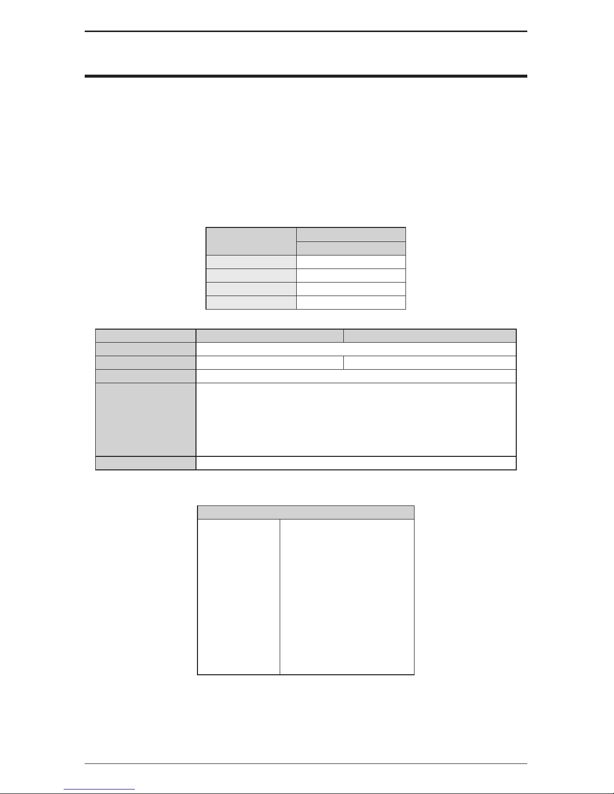
3.02 DUTY CYCLES
Duty Cycle
MIG Gun
250 AMP
10% 320
35% 290
80% 250
100% 195
The above duty cycles were established by testing under the following parameters:
Parameter MIG (metal inert gas) MAG (metal active gas)
Type of Voltage D.C.
Shielding Gas Argon Argon/CO2 Mixed Gas (80/20, 75/25)
Gas Flow Rate 30-35 CFH (14,2- 16,5 l/m)
Gun Cable Length
10 ft. (3 m)
12 ft. (3,7 m)
15 ft. (4,6 m)
20 ft. (6 m)
25 ft. (7,6 m)
Electrode Polarity Positive
Wire Diameter
Wire (Continuous Electrode) Size
250 amp
.023" (0,6 mm)
.030" (0,8 mm)
.035" (0,9 mm)
.040" (1,0 mm)
.045" (1,2 mm)
.052" (1,3 mm)
3/64” (1,2 mm)
1/16” (1,6 mm)
5/64” (2,0 mm)
3/32” (2,4 mm)
7/64” (2,8 mm)
1/8” (3,2 mm)
Page 9
SAFETY AND OPERATING INSTRUCTIONS
789200015
3.03 TWECO® FUSION 250A MIG GUN SELECTION GUIDE
Rear
Connection
250 AMP MIG Gun*
Rear Connector
(Replacement)
Part Number
Stock Number
Part Number
Stock Number
Part Number
Stock Number
Part Number
Stock Number
Part Number
Stock Number
Part Number
Stock Number
10 ft cable 12 ft cable 15 ft cable 20 ft cable 25 ft cable
Tweco
®
FV210-3545
1023-1059
FV212-3545
1023-1060
FV215-3545
1023-1061
FV220-3545
1023-1062
FV225-3545
1023-1063
350-174H
2035-2110
Miller
®
FV210M-3545
1023-1067
FV212M-3545
1023-1068
FV215M-3545
1023-1069
FV220M-3545
1023-1070
FV225M-3545
1023-1071
350-174MH
2035-2111
Lincoln
®
----
FV212L-3545
1023-1084
FV215L-3545
1023-1085
---- ----
350-174LH
2035-2112
Euro-Kwik
FV210X-3545
1023-1089
FV212X-3545
1023-1090
FV215X-3545
1023-1091
----
FV225X-3545
1023-1092
174EX-1
2040-2276
252i
ThermalArc
---- ----
FV215TA3545
1023-1097
---- ----
350-174H
2035-2110
*Rear connector supplied as standard
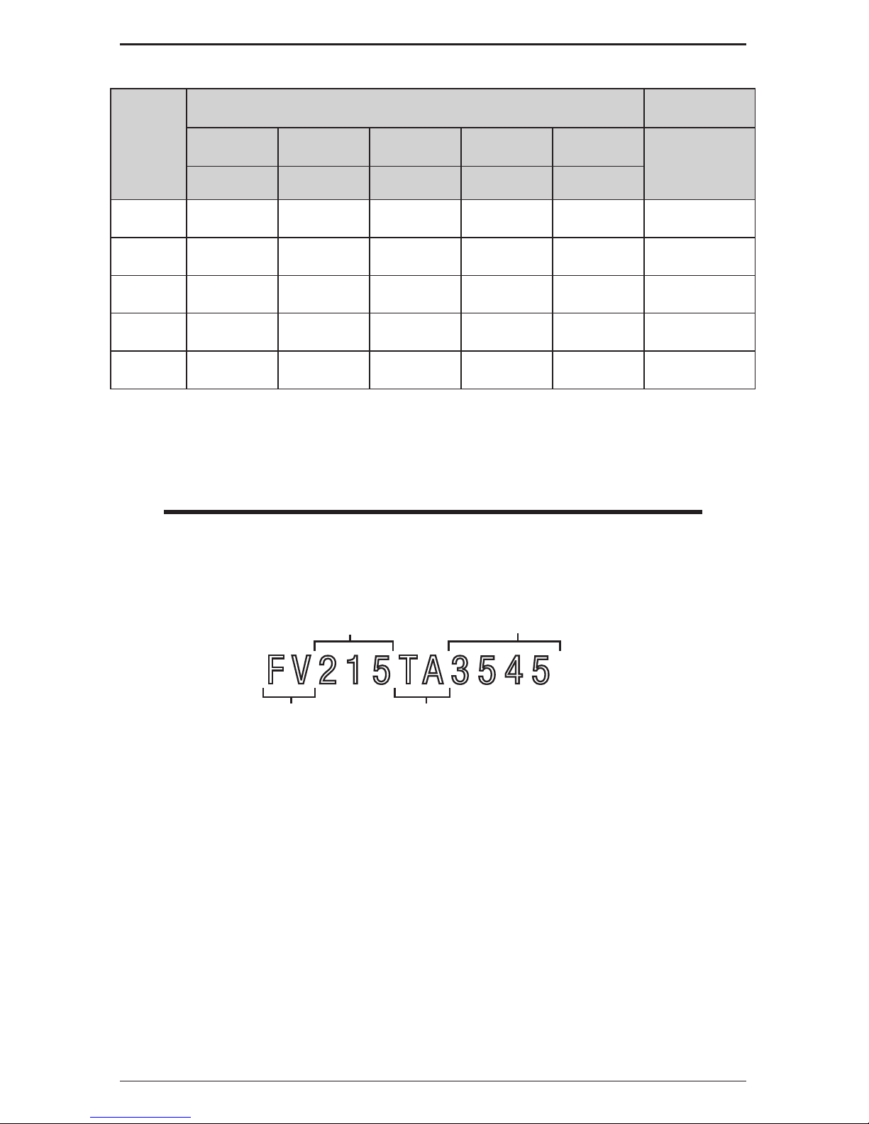
3.04 TWECO FUSION 250A MIG GUN PART NUMBER
IDENTIFICATION
NOTE
Tweco Fusion MIG guns, as a general rule, have a specific nomenclature
incorporated within each part number to help determine the wire size of each
MIG gun.
Example Part Number:
FV215TA3545
T=Tweco
TA=Tweco (Bundle)
L=Lincoln
M=Miller
X, XE=Euro-Kwik
Fusion Velocity
15 foot (5 M) cable
.035"-.045" Wire Capacity
(0,9 mm - 1,2 mm)
So a part number "FV215TA3545" would identify the MIG gun as a: Tweco Fusion 250A MIG
Gun bundle pack with a 8-pin rear connector, 15 foot long cable and having a 0.035" to 0.045"
diameter wire capacity.
So a part number"FV2253545" would identify the MIG gun as a: Tweco Fusion 250A MIG Gun
with a 4-pin Tweco rear connector, 25 foot long cable and having a 0.035" to 0.045" diameter
wire capacity.
MILLER is a registered trademark of Miller Electric Mfg. Co.; ESAB is a registered trademark of ESAB AB; LINCOLN is
a registered trademark of LINCOLN Electric Co.; The aforementioned registered trademarks are no way affiliated with
Tweco Products, Inc. or Victor Technologies, Inc. Tweco is a registered trademark of Victor Technologies, Inc.
Page 10

8
SAFETY AND OPERATING INSTRUCTIONS
89200015
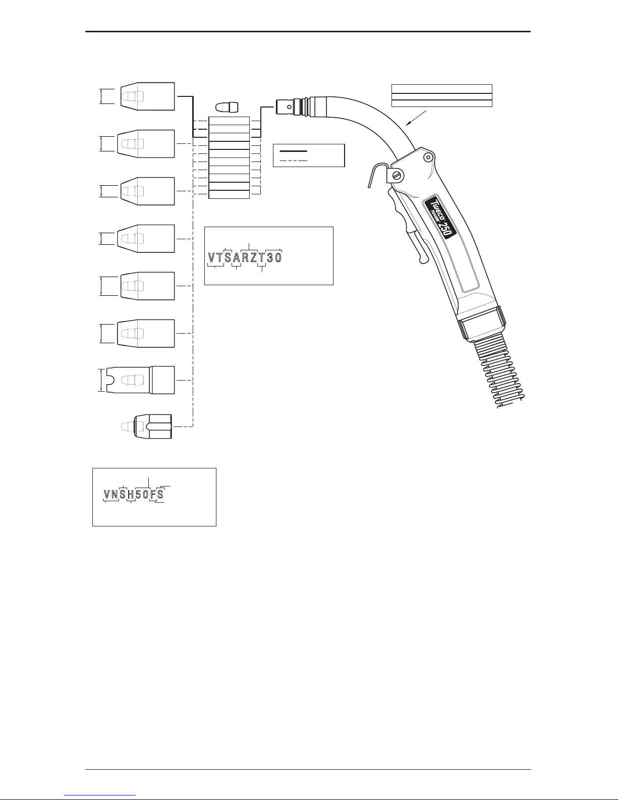
3.04 VELOCITY CONTACT TIP IDENTIFICATION
Velocity Contact Tips may be identified by the tip type and the part number marking for each tip.
Example Part Number:
VTSARZT30
Velocity
Tip
Blank=CU,
RZ=CHROM ZIRC,
RS=SILVER ZIRC
T=Tapered,
Blank=None
S=Small,
M=Medium,
L=Large
A=Aluminum,
Blank=Other
Wire Size: 23=0.023” 116=1/16”
30=0.030” 564=5/64”
35=0.035” 332=3/32”
40=0.040” 764=7/64”
45=0.045” 18=1/8”
52=0.052” 364=3/64”
So a part number "VTSARZT30" would be: Velocity Tip Type, Small Size, Aluminum, RZ Alloy,
Tapered for wire size 0.030" diameter.
A part number "VTM40" would be: Velocity Tip Type, Medium Size, CU, wire size 0.040" diameter.
3.05 VELOCITY CONTACT TIP NOZZLE IDENTIFICATION
Nozzles for the Velocity contact tip Tweco Fusion MIG Guns may be identified by their type and part
number marking on each nozzle.
Example Part Number:
Blank=Standard,
H=Heavy Duty
VNSH50FS
Velocity
Nozzle
Blank=Std Recess,
F=Flush,
P=Protrude,
R= Recess ¼” (6.35mm)
FAS=Spot Weld
FC=Flux Core
S=Small Nozzle,
M=Medium Nozzle,
L=Large Nozzle
Orifice Opening Size: 37=3/8” 62=5/8”
50=1/2” 75=3/4”
Blank=Threaded,
S=Slip
So a part number "VNSH50FS" would be: Velocity Nozzle Type, Small Nozzle Size, Heavy Duty,
orifice opening size of 0.50 inch, Flush end, Slip fit.
A part number "VNS50" would be: Velocity Nozzle Type, Small Nozzle Size, Standard Duty,
orifice opening size of 0.50 inch, Standard Recess end, Threaded fit.
3.06 VELOCITY 250 AMP CONDUCTOR TUBE IDENTIFICATION
Conductor tubes for the Velocity Contact Tip on the Tweco Fusion MIG Guns may be identified by their
type and part number marking on each tube.
Example Part Number:
FVCTS45
Fusion
Velocity
Conductor Tube
Bend Angle: 45˚, 60˚, or 180˚
S=Small Tip,
M=Medium Tip,
L=Large Tip
So a part number "FVCTS45" would be: Tweco Fusion Gun Type, Velocity 250 Amp Conductor
Tube, Small Tip Size, 45 degree bend.
A part number "FVCTM60" would be: Tweco Fusion Gun Type, Velocity 250 Amp Conductor
Tube, Medium Tip Size, 60 degree bend.
Page 11
SAFETY AND OPERATING INSTRUCTIONS
989200015
SECTION 4:
MIG GUN INSTALLATION
NOTE
Be certain that the end user (welder, operator, or helper) reads and understands
these instructions. Be certain that the welder also reads Section 1 “Safety
Precautions.”
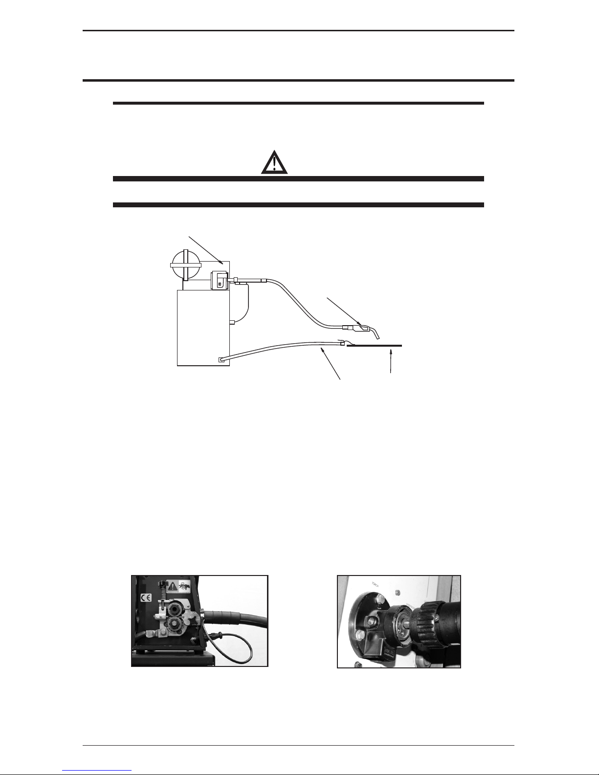
WARNING
Electric shock can cause injury or death.
POWER
SOURCE
WIRE FEEDER
GROUND
WORK PIECE
GUN
Figure 1: Standard MIG Gun Installation
4.01 DIRECT PLUG MIG GUN INSTALLATION
Direct plug MIG guns install by directly inserting the rear connector plug into the feeder wire
guide outlet (see figure 2) and tightening the plug retaining screw. All models of MIG guns,
except the Euro-Kwik guns, require a control wire assembly to attach the MIG gun trigger
leads to the feeder. The control wire assemblies plug into the rear connector case of the MIG
gun, and into the control wire receptacle on the feeder. Euro-Kwik connections are installed by
inserting the gun connection into the feeder receptacle, aligning the conduit plug first, then the
gas plug. Push until all fittings are seated, then tighten the nut hand tight as shown in figure 3.
Figure 2
Figure 3
Page 12

10
SAFETY AND OPERATING INSTRUCTIONS
89200015
4.02 TWECO® MIG-KWIK CONNECTION AND ADAPTER KIT
INSTALLATION
Installation of a Tweco MIG gun with a Tweco connector plug, may require an adapter kit. Choose
the correct adapter kit for your wire feeder from the Adapter Kit Listing Form No. TLAK-97 for
more detail. To install, follow the instructions furnished with the adapter kit. Figure 4 shows
the general adapter kit installation.
Receptacle
(TLAK-1 or 6TLAK-1)
Receptacle
(TAK-1 or 6TAK-1)
ADAPTER PLUG
WIRE FEEDER
GAS HOSE
GAS HOSE
POWER CABLE
CONTROL WIRE
MIG GUN
Figure 4
1. Screw adapter plug into the receptacle and tighten.
2. Insert the adapter plug and receptacle into the wire feeder wire guideout. Tighten the
wire guide attachment screw.
3. If needed, attach a proper sized welding cable from the welding power source to the
receptacle power connection.
4. Attach a gas hose to the receptacle and to the feeder gas solenoid.
NOTE
When using an adapter kit, the gas must be attached to the receptacle to provide
gas to the MIG gun. If the feeder gas supply is attached to the feeder wire guideout
block, it must be rerouted to the receptacle.
5. Insert the MIG gun rear connection plug into the receptacle and tighten the attachment
screw.
6. Attach the control wire plug assembly to the wire feeder MIG gun control circuit. Then
plug the flat double female plug into the MIG gun.
The gun should now be installed and ready to feed wire as recommended by the feeder
manufacturer.
Page 13
SAFETY AND OPERATING INSTRUCTIONS
1189200015
SECTION 5: REPLACEMENT INSTRUCTIONS
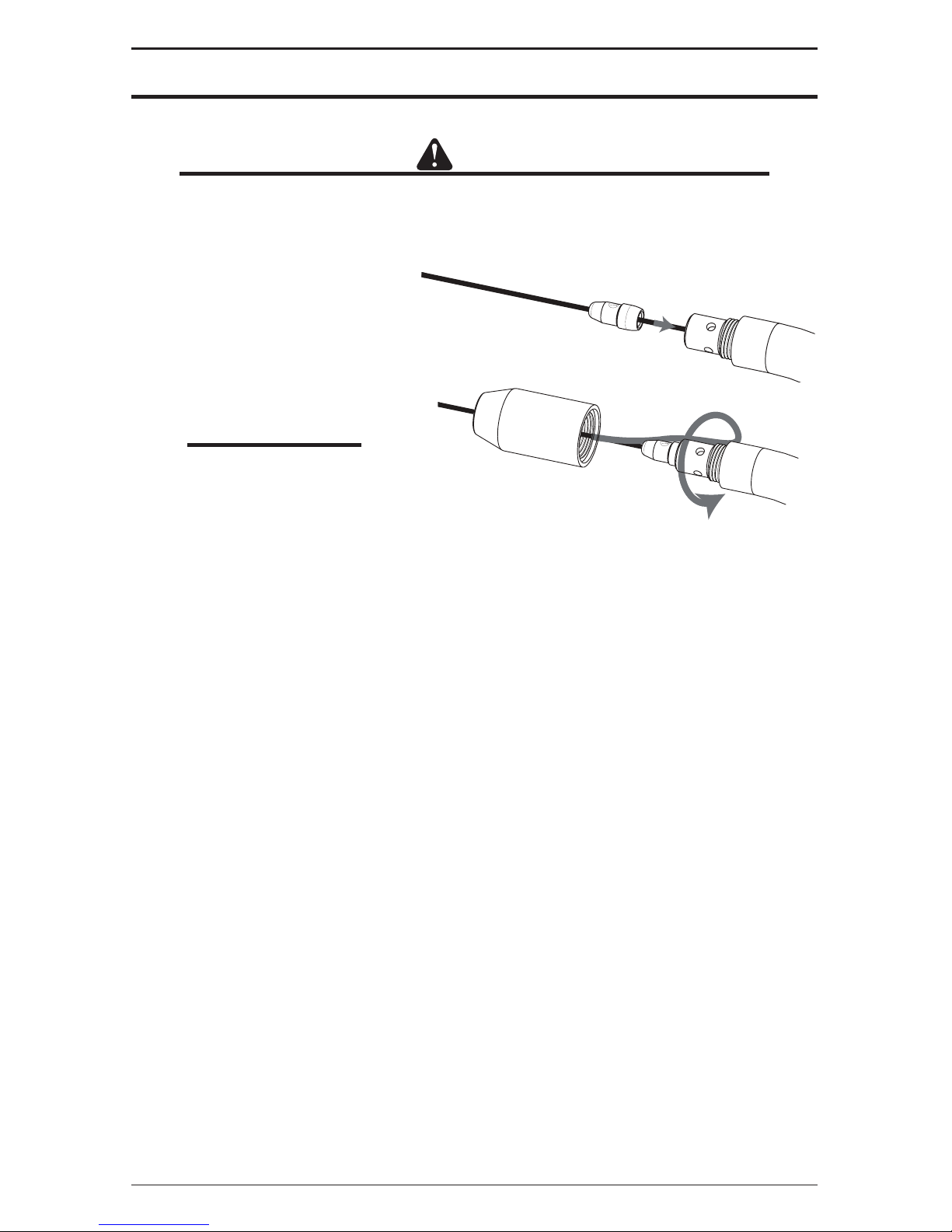
5.01 REPLACING VELOCITY CONTACT TIP
CAUTION
While nozzle and contact tip are removed, maintain an adequate distance of the
wire from metal objects to avoid burnbacks to conduit or conductor tube.
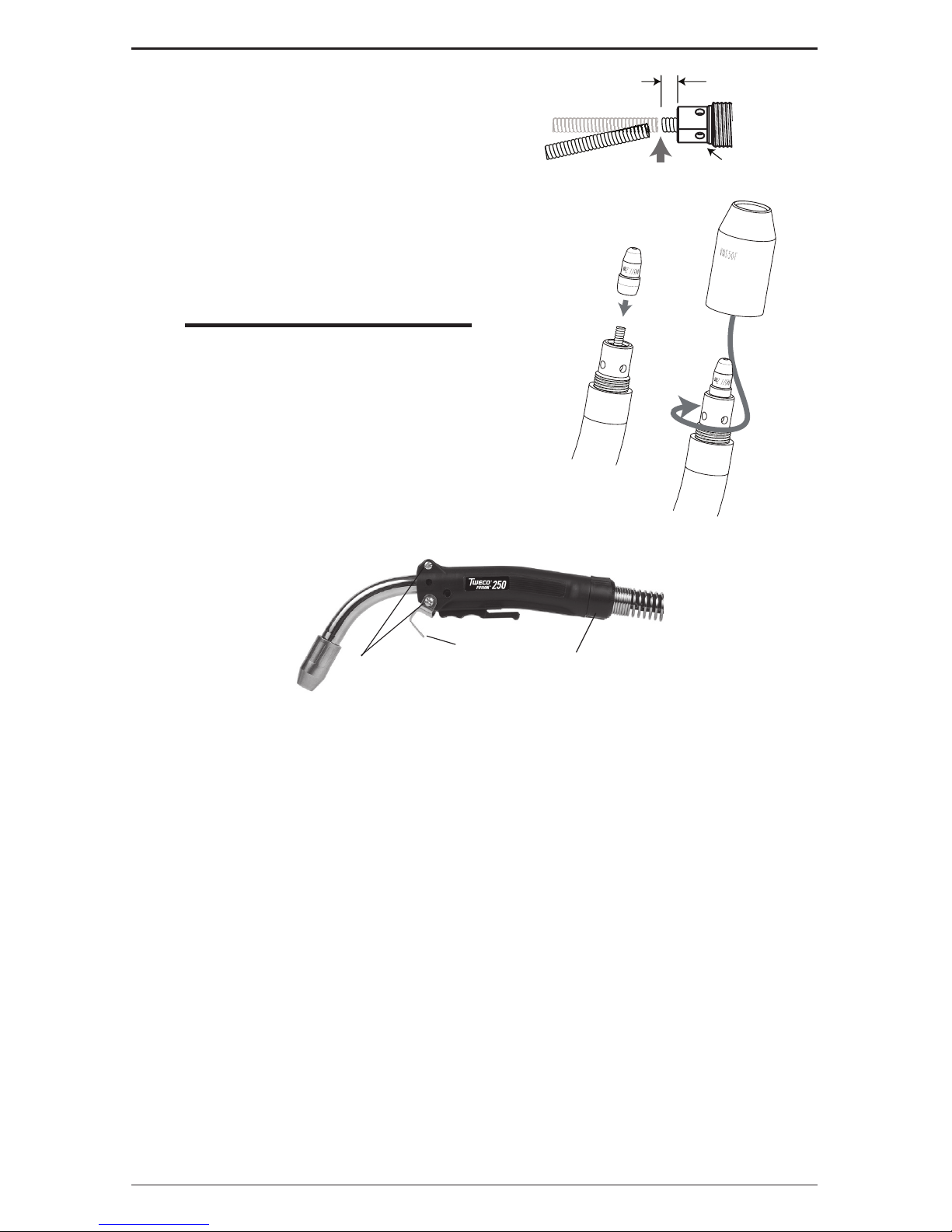
1. Remove worn nozzle and tip. (Clean nozzle if reusing.)
2. Slide new contact tip over
the conduit end and into the
conductor tube end.
3. Replace the nozzle. Hand tighten
(Nozzle secures tip).
NOTE
For proper operation the
nozzle MUST be tight.
4. Trim wire to desired stick out.
The MIG gun is now ready operation.
5.02 REPLACE CONDUCTOR TUBE
The conductor tube is attached to the Tweco® Fusion handle by two set screws on the side of
the handle. To remove:
1. Remove the front end consumables from the conductor tube.
2. Loosen the conduit liner set screw with a 5/64" Allen wrench (supplied) and then
loosen the socket head cap screw securing the conductor tube in place inside the
handle with a 5/32" Allen wrench.
3. Remove conductor tube.
4. Slide the new tube over the liner and insert into the brass connection within the handle.
Confirm the tube is correctly aligned with the MIG Gun handle and wrench tighten the
socket head cap screw.
5. Tighten the conduit set screw down against the liner. Do not overtighten to avoid
damaging the liner.
6. Re-assemble the front end consumables.
The MIG gun is now ready for operation.
Page 14
12
SAFETY AND OPERATING INSTRUCTIONS
89200015
Conduit liner set screw
Socket head cap screw
5.03 CONDUIT IDENTIFICATION AND REPLACEMENT
The procedure for removal and installation of a wire conduit is similar for all Tweco MIG guns. Conduits
may be identified by the type of conduit stop and the part number marking on each conduit stop.
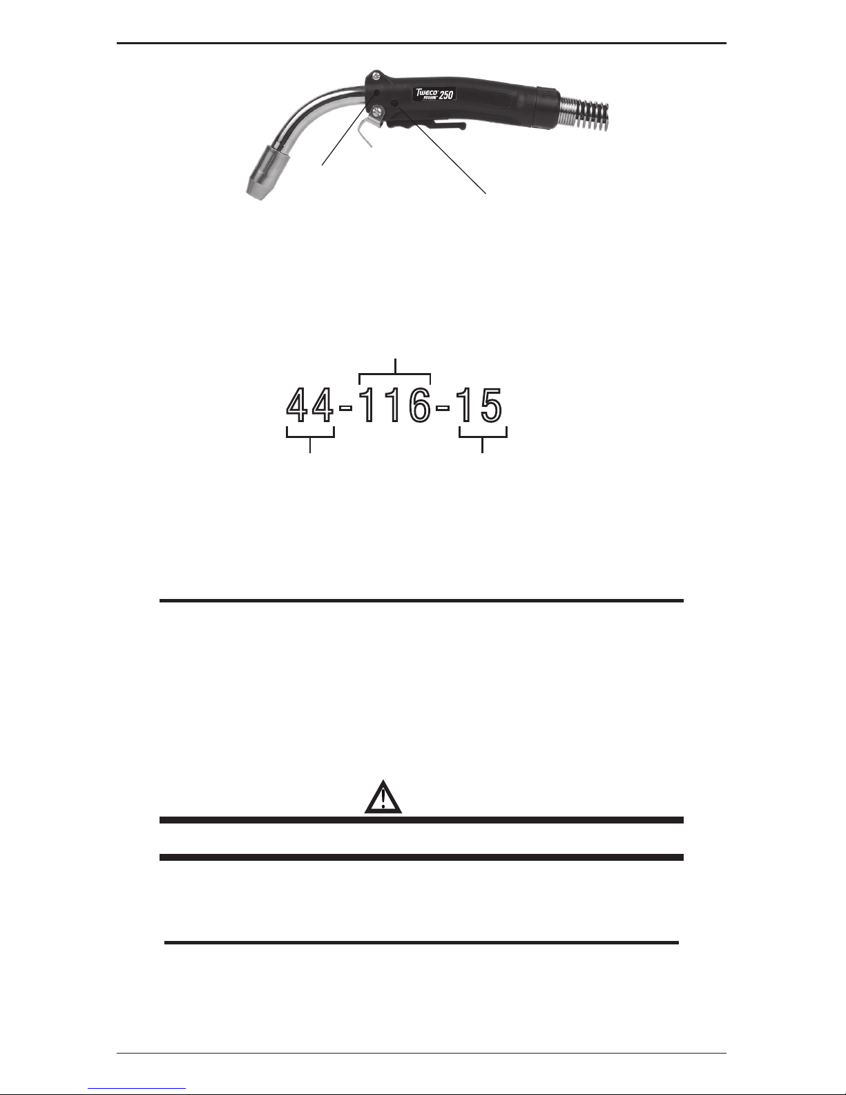
Example Part Number:
44-116-15
44 Series
1/16" (1,6mm) Wire Capacity
Liner length in feet
Conduit Removal
1. Lay the MIG gun out on a table or on the floor in a straight line. Make sure the gun is
fully extended and all twists in the cable are removed.
2. Remove the nozzle and tip.
NOTE
On Miller® Direct Plug MIG guns, remove the nipple on the end of the connector
plug. On Euro-Kwik connections, remove the conduit retaining cap.
3. Loosen the conduit set screw in the front of the gun. This is usually located at the
front of the handle. Then loosen the conduit set screw in the rear connector plug.
4. Grip the conduit stop and remove the conduit with a twisting motion. On Miller® Direct
Plug MIG guns, twisting the rear of the gun approximately one revolution clockwise
will raise the conduit stop out of the connector plug recess.
Conduit Installation - Velocity Contact Tip Style
WARNING
Failure to follow Conduit Installation Instructions will cause wire feed issues.
1. Uncoil the conduit and lay it in a straight line. Insert the conduit into the rear connector plug.
Push the conduit into the gun with short strokes.
NOTE
If the conduit hangs up gently whip the cable while applying pressure to the
conduit. New liners must be cut to the correct length.
2. When the conduit is completely in the gun, tighten the rear conduit set screw. On Miller®
guns, reinstall the nipple. On Euro-Kwik guns, reinstall the conduit retaining cap.
Page 15
SAFETY AND OPERATING INSTRUCTIONS
1389200015
IMPORTANT!
3. The new conduit liner will need to be cut to length.
This can be done by trimming the conduit to the
appropriate length.
1/8” (3,2 mm)
Velocity
Conductor Tube
4. File the cut conduit end to remove burrs.
5. Replace the contact tip.
6. Replace the nozzle. Hand tighten
(Nozzle secures tip).
NOTE
For proper operation the nozzle MUST
be tight.
The MIG gun is now ready to be reinstalled on the
feeder.
5.04 REPLACING HANDLE, TRIGGER
Remove the MIG gun from the feeder prior to beginning these steps.
Handle screws Back Cap
Gun Hanger
1. Lay MIG gun on side, screw side up and remove both handle screws at the front of the
gun handle.
2. Remove the small screw from the other side of the gun hanger clip and remove the
gun hanger clip being careful to keep all internal components in place.
3. Lay the gun back down on its side and untwist the handle back cap.
4. Remove the top handle half being careful to keep all components in place in the lower
handle half.
5. (Follow this step ONLY if the trigger is to be replaced.) Lift out the molded trigger, the
trigger mechanism, and disconnect the lead wires. Connect the wires to the new trigger
mechanism then place the molded trigger and new trigger in the lower handle half.
6. Place the new top handle half on the old lower handle half and gently flip the gun over.
Replace the old lower handle half with the new lower handle half. Molded trigger should
move within the handle.
7. Flip the gun back to the screw side up and press the handle halves together until they
bottom. Be careful not to pinch the trigger lead wires.
8. Put the gun hanger in place and install the two handle screws. Rotate the gun handle
to the other side and install the small gun hanger clip screw.
9. Slide the Back Cap into place and twist onto the handle end.
The MIG gun is now ready to be reinstalled on the feeder.
Page 16
14
SAFETY AND OPERATING INSTRUCTIONS
89200015
SECTION 6:
CABLEHOZ® REPAIR
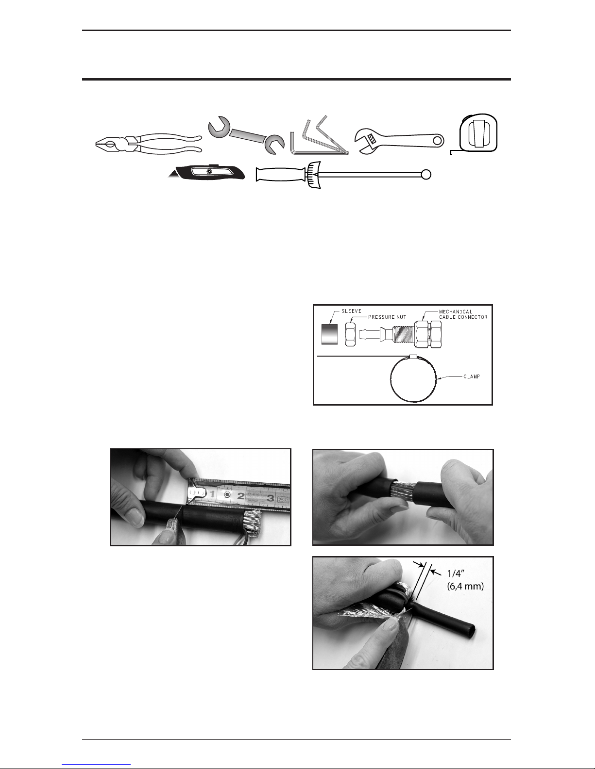
6.01 TOOLS REQUIRED
6.02 REPAIR OF CABLEHOZ®
A. Back-End Repair
1. Disassemble the rear case to expose the rear connector assembly and pull the assembly
away from the rear case.
2. Cut the Cablehoz® to remove the damaged area.
3. Use replacement connector assembly,
Part No. MS172-RK (Stock No. 2060-
2134) on 250 Amp Tweco® Fusion MIG
Guns.
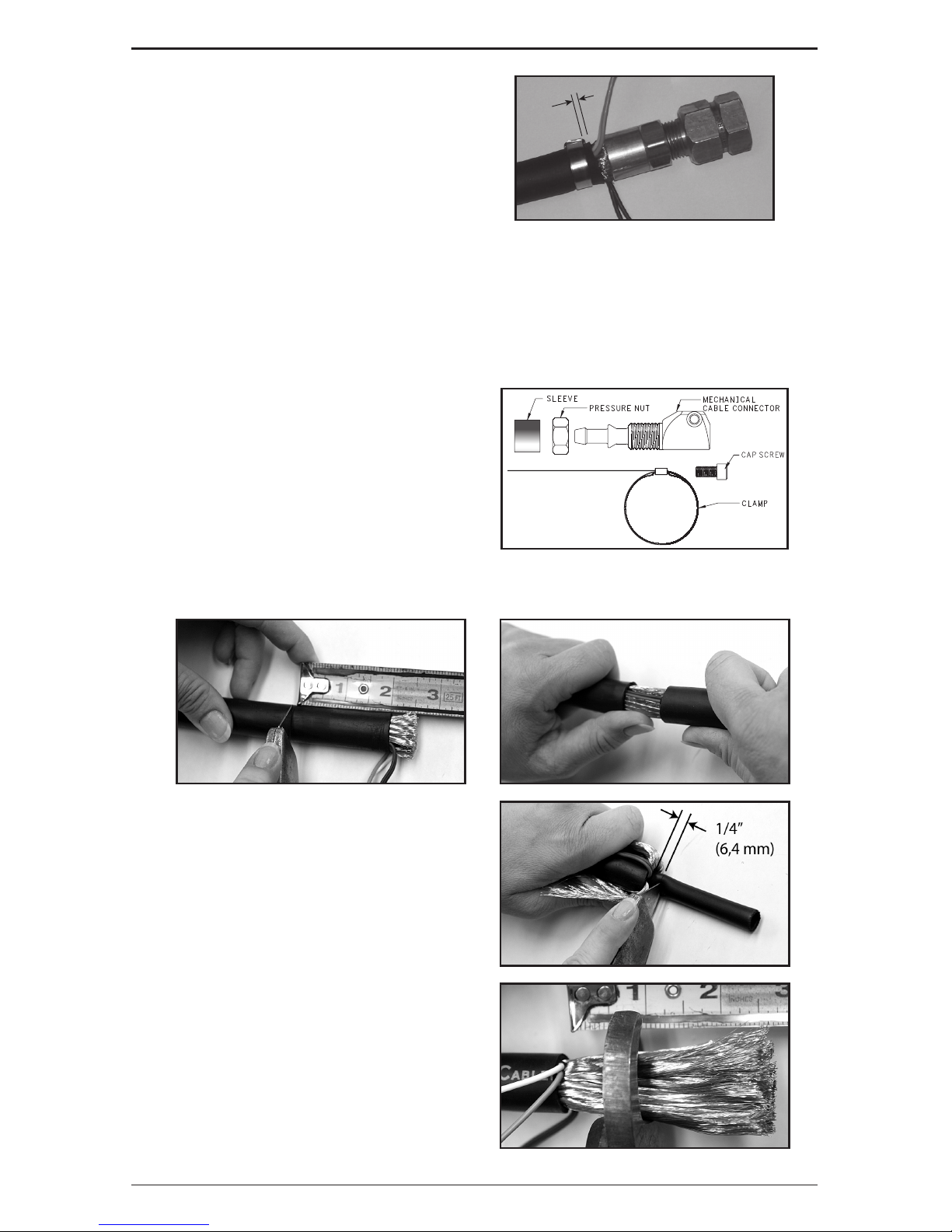
4. Measure back 2-1/2" (63,5 mm) from the end of the Cablehoz and cut away the outer
jacket of the cable, being careful not to cut the copper strands and or lead wires.
5. Pull the copper strands and lead
wires away from the inner core tube
that is exposed and cut away leaving
approximately ¼" (6,35 mm) past the
end of the end of the Cablehoz.
Page 17
SAFETY AND OPERATING INSTRUCTIONS
1589200015
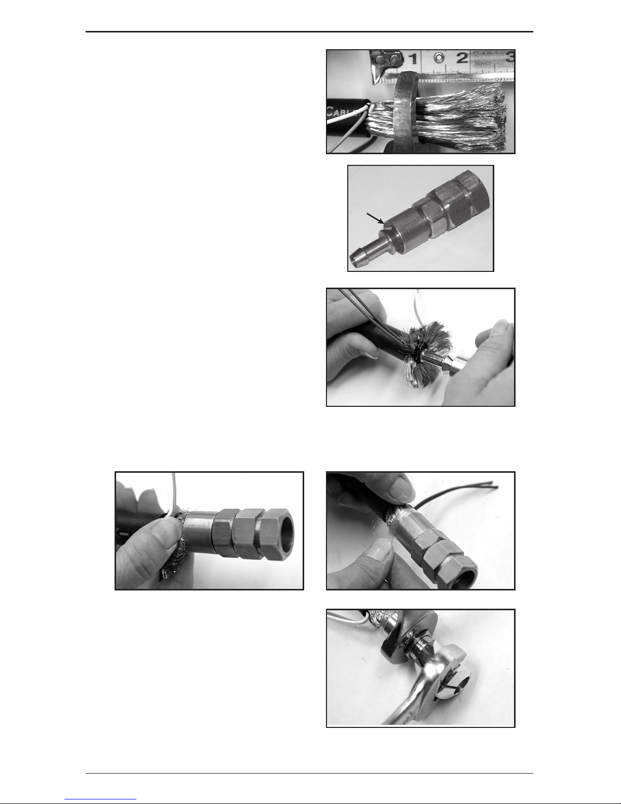
6. Cut the copper strands to a length of ¾"
(19,05 mm) while leaving the wire leads
intact.
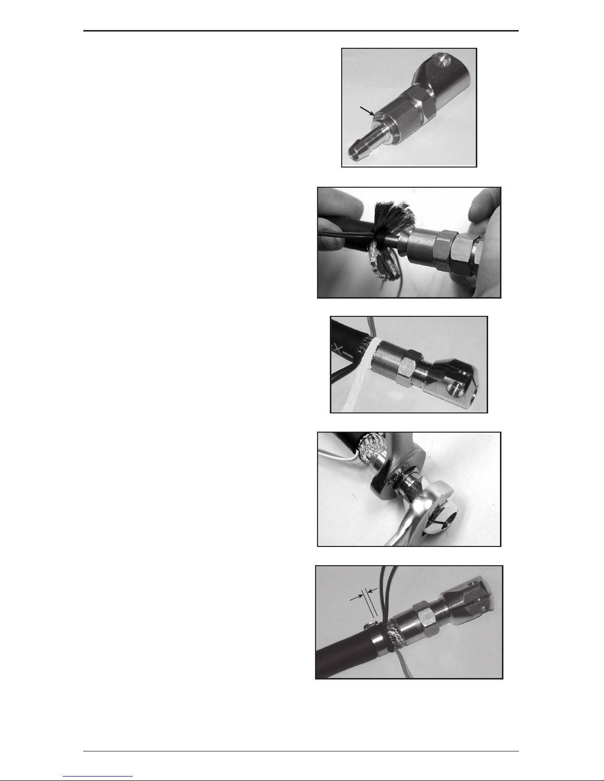
7. Thread the pressure nut onto the
replacement rear connector until it
bottoms out and then slide the sleeve
over the connector.
Note: Make sure the bevel is facing the
right direction.
Bevel
8. Insert the replacement connector nipple
into the inner core tube of the Cablehoz.
It is recommended to use a small amount
of non-petroleum based lubricant* to help
the connector to slide into the tube. The
core tube should bottom out against the
shoulder, approximately 15/16" (23,8
mm) onto the connector.
*A small amount of white glue works well.
9. Push the copper strands underneath the sleeve. It is recommended that a 1/8” glass
filament tape be wrapped around the exposed copper to keep the copper strands together
when tightening the pressure nut.
10. Begin to turn the pressure nut counterclockwise which will force the copper
strands & sleeve against and then under
the machined taper on the connector.
Use Torque Wrench and wrench to
perform this task.
11. Torque the pressure nut to 250 inch
pounds, +/-50 inch pounds, (28,2 newton
meters, +/- 5,6 newton meters).
Page 18
16
SAFETY AND OPERATING INSTRUCTIONS
89200015
12. Apply clamp over outside cable and
tighten. Trim excess clamp.
13. Connect lead wires accordingly.
14. Re-assemble the rear case.
Approx.
0.2” (5mm)
B. Front-End Repair
1. Disassemble the front handle halves to expose the front connector assembly and pull
the assembly from the front handle case.
2. Cut the Cablehoz® to remove the damaged area.
3. Use replacement connector assembly,
Part No. MS102-RK (Stock No. 2060-
2132) on 250 Amp Tweco® Fusion MIG
Guns.
4. Measure back 2-1/2” (63,5 mm) from the end of the Cablehoz and cut away the outer
jacket of the cable, being careful not to cut the copper strands and or lead wires.
5. Pull the copper strands and lead
wires away from the inner core tube
that is exposed and cut away leaving
approximately ¼” (6,35 mm) past the
end of the end of the Cablehoz.
6. Cut the copper strands to a length of ¾”
(19,05 mm) while leaving the wire leads
intact.
Page 19
SAFETY AND OPERATING INSTRUCTIONS
1789200015
7. Thread the pressure nut onto the
replacement front connector until it
bottoms out and then slide the sleeve
over the connector.
Note: Make sure the bevel is facing the
right direction.
Bevel
8. Insert the replacement connector nipple
into the inner core tube of the Cablehoz.
It is recommended to use a small amount
of non-petroleum based lubricant* to help
the connector to slide into the tube. The
core tube should bottom out against the
shoulder, approximately 15/16” (23,8
mm) onto the connector.
*A small amount of white glue works well.
9. Push the copper strands underneath the
sleeve. It is recommended that a 1/8”
glass filament tape be wrapped around
the exposed copper to keep the copper
strands together when tightening the
pressure nut.
10. Begin to turn the pressure nut counterclockwise which will force the copper
strands & sleeve against and then under
the machined taper on the connector.
Use Torque Wrench and wrench to
perform this task.
11. Torque the pressure nut to 250 inch
pounds, +/-50 inch pounds, (28,2 newton
meters, +/- 5,6 newton meters).
12. Apply clamp over outside cable and
tighten. Trim excess clamp.
13. Connect lead wires accordingly.
14. Re-assemble the front end.
Approx.
2” (5mm)
Page 20

18
SAFETY AND OPERATING INSTRUCTIONS
89200015
This page intentionally blank.
Page 21

SAFETY AND OPERATING INSTRUCTIONS
1989200015
SECTION 7:
MAINTENANCE AND TROUBLESHOOTING
Contact tips and nozzles should be cleaned frequently. Spatter buildup may cause bridging
between nozzle and tip. This could cause electrical shorting between the nozzle and work
piece as well as poor or improper gas flow. Regularly inspect the conductor tube, handle,
cable, and other parts of the MIG Gun for abrasion, cuts, or undue wear. Replace or repair any
parts found deficient.
Problem Possible Cause Corrective Action
Wire feed inconsistent
or not smooth
1. Loose contact tip. 1. Tighten nozzle.
2. Excessively worn contact tip. 2. Replace contact tip.
3. Spatter buildup on end of
contact tip.
3. Clean or replace contact tip.
4. Sharp bends or kinks in
conduit.
4. Straighten or replace conduit.
5. Dirty or plugged conduit. 5. Replace conduit.
6. Conduit pulled back from
contact tip.
6. Reposition conduit and cable.
7. Machine improperly adjusted. 7. Reset machine per machine
and wire manufacturers’
recommendations.
MIG Gun is running hot
1. Loose contact tip. 1. Tighten nozzle.
2. Loose power connections. 2. Inspect complete gun for loose
connections and repair.
3. Loose or undersize ground
cable or ground clamp.
3. Tighten or replace as required.
4. Operating gun above
recommended amperage
rating.
4. Readjust machine to correct
setting for size of gun being used.
5. Operating gun above
recommended duty cycle
rating.
5. Readjust machine to correct
setting for size of gun being used.
Porous weld
1. Poor or improper gas flow. 1. Check gas flow out of gun nozzle.
Check for leaks or restrictions in
gas hoses and connections.
2. Dirty or contaminated wire. 2. Change wire.
3. Base metal contaminated. 3. Replace base metal.
Conduit gets hung-up
inside of the gun
1. Burr on the end of the cut
conduit.
2. Conduit liner has kinks.
1. Remove the burr with a file.
2. Replace conduit.
Page 22
20
SAFETY AND OPERATING INSTRUCTIONS
89200015
SECTION 8:
250 AMP REPLACEMENT PARTS
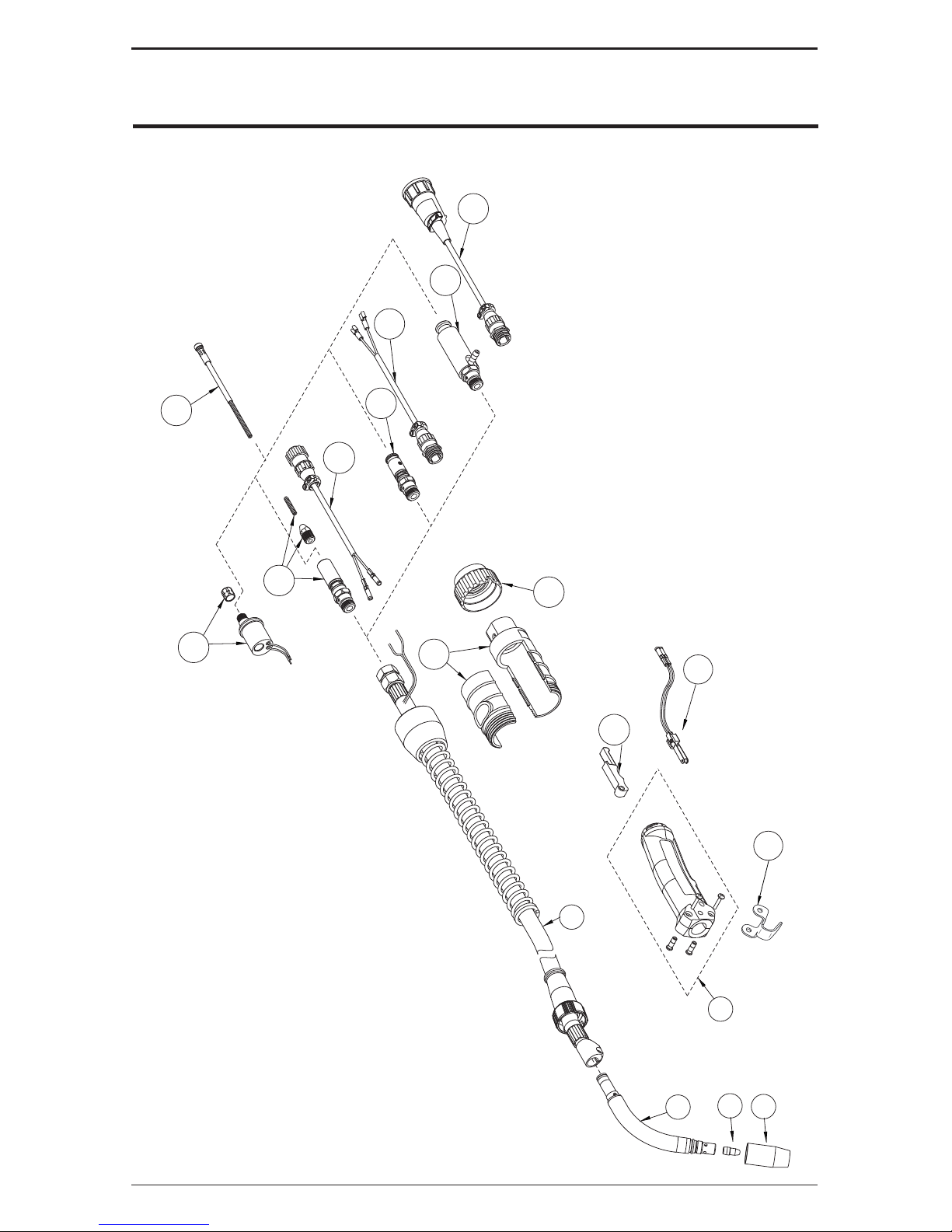
8.02 TWECO® FUSION 250 A MIG GUN PARTS
13b
13a
10a
11a
12a
11
10
12
13
14
9
2
5
7
8
6
1
15
Page 23

SAFETY AND OPERATING INSTRUCTIONS
2189200015
Item No. Part No. Stock No. Description
1*
VNS-50 1220-1201 Velocity Nozzle
VNS-50F 1220-1200 Flush Velocity Nozzle
VNS-62 1220-1203 Velocity Nozzle
VNS-62F 1220-1202 Flush Velocity Nozzle
VNS-37 1220-1206 Velocity Nozzle
VNS-37F 1220-1204 Flush Velocity Nozzle
VNS-75FAS 1220-1205 Spot Welding Velocity Nozzle
** **
2*
VTS-23 1110-1308 0.023” Velocity Contact Tip
VTS-30 1110-1309 0.030” Velocity Contact Tip
VTS-35 1110-1310 0.035” Velocity Contact Tip
VTS-40 1110-1311 0.040” Velocity Contact Tip
VTS-45 1110-1312 0.045” Velocity Contact Tip
VTSA-364 1110-1313 3/64” Velocity Contact Tip (for Aluminmum)
VTS-52 1110-1314 0.052” Velocity Contact Tip
VTS-116 1110-1315 1/16” Velocity Contact Tip
VTSA-116 1110-1317 1/16” Velocity Contact Tip (for Aluminmum)
VTS-564 1110-1316 5/64” Velocity Contact Tip
** **
5*
FVCT-S45 1620-1369 Velocity 45° Conductor Tube
FVCT-S60 1620-1368 Velocity 60° Conductor Tube
6 F84 2060-2126 Handle – Standard
7 ELC94 2060-2647 Trigger– Standard
8 ELC94-BL 2060-2671 Trigger Blade Assembly
9
NS
MS210 1720-2115 Cablehoz® Assembly - 10 ft (3 m)
MS212 1720-2116 Cablehoz Assembly - 12 ft (4 m)
MS215 1720-2117 Cablehoz Assembly - 15 ft (5 m)
MS225 1720-2118 Cablehoz Assembly - 25 ft (8 m)
MS212X 1720-2107 Cablehoz Assembly, Euro-Kwik - 12 ft (4 m)
MS215X 1720-2108 Cablehoz Assembly, Euro-Kwik - 15 ft (5 m)
MS225X 1720-2109 Cablehoz Assembly, Euro-Kwik - 25 ft (8 m)
9a MS102-RK 2060-2132 Cablehoz Front Mechanical Connector Replacement Kit
9b MS172-RK 2060-2134 Cablehoz Rear Mechanical Connector Replacement Kit
9c 172X-M 2020-2181 Cablehoz Rear Mechanical Connector Replacement Kit For Euro-Style
10
10a 350-174MH 2035-2111 Miller® Rear Connector
10b WM-354M 2030-2075 Miller Control Wire & Plug
11
11a 350-174H 2035-2110 Tweco® Rear Connector
11b MS354-TAJ 2060-2139 Tweco Control Wire
12
12a 350-174LH 2035-2112 Lincoln® Rear Connector
12b MS-354DS-LJ 2060-2137 Lincoln Control Wire & Plug
13
174EX-1 2040-2276 Euro-Kwik Connection Assy
13a 174X-2 2040-2177 Euro-Kwik Nut
13b X6RC 2060-2006 Euro-Kwik Connector Case
14 ** ** Conduit
15 152 2020-2152 Gun Hanger
NS = Not Shown
** Refer to Tweco Catalog No. for specific parts.
* Patent Pending
MILLER is a registered trademark of Miller Electric Mfg. Co.; ESAB is a registered trademark of ESAB AB; LINCOLN is
a registered trademark of LINCOLN Electric Co.; The aforementioned registered trademarks are no way affiliated with
Tweco Products, Inc. or Victor Technologies, Inc. Tweco is a registered trademark of Victor Technologies, Inc.
Page 24
22
SAFETY AND OPERATING INSTRUCTIONS
89200015
8.02 TWECO® FUSION MIG GUN CONSUMABLES
VNS-50F
5/8” (15,9 mm)
VNS-37
3/8” (9,5 mm)5/8” (15,9 mm)
VNS-75FAS
VNS-50
1/2” (12,7 mm) 1/2” (12,7 mm)
VNS-37F
3/8” (9,5 mm)
VNS-62F
VNS-62
3/4” (19,1 mm)
60° FVCTS60
45° FVCTS45
VTSARZT30
Velocity
Tip
Blank=CU,
RZ=CHROM ZIR,
RS=SILVER ZIR
T=Tapered,
Blank=None
S=Small,
M=Medium,
L=Large
A=Alum,
Blank=Other
Wire Size: 23=0.023” 116=1/16”
30=0.030” 564=5/64”
35=0.035” 332=3/32”
40=0.040” 764=7/64”
45=0.045” 18=1/8”
52=0.052” 364=3/64”
Blank=Standard,
H=Heavy Duty
VNSH50FS
Velocity
Nozzle
Blank=Std Recess,
F=Flush,
P=Protrude,
R= Recess ¼” (6.35mm)
FAS=Spot Weld
S=Small Nozzle,
M=Medium Nozzle,
L=Large Nozzle
Orifice Opening Size: 37=3/8” 62=5/8”
50=1/2” 75=3/4”
Blank=Threaded,
S=Slip
VELOCITY CONTAC T TIP IDENTIFICATION
VELOCITY NOZZLE IDENTIFICATION
Velocity
Nozzle
Velocity
Contact Tip
VTS-23
VTS-45
VTSA-116
VTS-564
VTS-52
VTS-116
VTS-364
VTS-35
VTS-40
VTS-30
Replacement Conductor Tubes
250A MIG GUN
OPTIONAL
STANDARD
VNS-FC
Page 25

SAFETY AND OPERATING INSTRUCTIONS
2389200015
This page intentionally blank.
Page 26

24
SAFETY AND OPERATING INSTRUCTIONS
89200015
SECTION 9:
STATEMENT OF WARRANTY
9.01 WARRANTY SCHEDULE
The warranty is effective below for the time stated in the Warranty Schedule beginning on the
date that the authorized distributor delivers the products to the purchaser. Victor Technologies,
Inc. reserves the right to request documented evidence of date of purchase.
Engine Driven Welders
Parts / Labor
Scout®, Rraider®, Explorer
™
Original Main Power Stators and Inductors 3 years / 3 years
Original Main Power Rectifiers, Control P.C. Boards 3 years / 3 years
All Other Original Circuits and Components Including, but not Limited to, Relays, Switches, Contactors,
Solenoids, Fans, Power Switch Semi-Conductors
1 year / 1 year
Engines and Associated Components are NOT Warranted by Thermal Arc®, Although Most are Warranted by
the Engine Manufacturer. SEE THE ENGINE MANUFACTURERS’ WARRANTY FOR DETAILS.
See the Engine
Manufacturers’ Warranty for
Details
GMAW/FCAW (MIG) Welding Equipment
Parts / Labor
Fabricator® 131, 181, 190, 210, 251, 281; Fabstar® 4030; PowerMaster® 320SP, 350, 350P,
400SP, 500SP, 500, 500P; Excel-Arc® 6045; Wire Feeders: Ultrafeed®, Porta-feed
®
Original Main Power Transformer and Inductor 5 years / 3 years
Original Main Power Rectifiers, Control P.C. Boards, Power Switch Semi-Conductors 3 years / 3 years
All Other Original Circuits and Components Including, but not Limited to, Relays, Switches, Contactors,
Solenoids, Fans, Electric Motors
1 year / 1 year
GTAW (TIG) & Multi-process Inverter Welding Equipment
Parts / Labor
160TS, 300TS, 400TS, 185AC/DC, 200AC/DC, 300AC/DC, 400GTSW, 400MST, 300MST, 400MSTP
Original Main Power Magnetics 5 years / 3 years
Original Main Power Rectifiers, Control P.C. Boards, Power Switch Semi-Conductors 3 years / 3 years
All Other Original Circuits and Components Including, but not Limited to, Relays, Switches, Contactors,
Solenoids, Fans, Electric Motors
1 year / 1 year
Plasma Welding Equipment
Parts / Labor
Ultima® 150
Original Main Power Magnetics 5 years / 3 years
Original Main Power Rectifiers, Control P.C. Boards, Power Switch Semi-Conductors 3 years / 3 years
Welding Console, Weld Controller, Weld Timer 3 years / 3 years
All Other Original Circuits and Components Including, but not Limited to, Relays, Switches, Contactors,
Solenoids, Fans, Electric Motors, Coolant Recirculators
1 year / 1 year
SMAW (Stick) Welding Equipment
Parts / Labor
Dragster™ 85
Original Main Power Magnetics 1 year / 1 year
Original Main Power Rectifiers, Control P.C. Boards 1 year / 1 year
All Other Original Circuits and Components Including, but not Limited to, Relays, Switches, Contactors,
Solenoids, Fans, Power Switch Semi-Conductors
1 year / 1 year
160S, 300S, 400S Parts / Labor
Original Main Power Magnetics 5 years / 3 years
Original Main Power Rectifiers, Control P.C. Boards 3 years / 3 years
All Other Original Circuits and Components Including, but not Limited to, Relays, Switches, Contactors,
Solenoids, Fans, Power Switch Semi-Conductors
1 year / 1 year
Page 27

SAFETY AND OPERATING INSTRUCTIONS
2589200015
General Arc Equipment Parts / Labor
Water Recirculators 1 year / 1 year
Plasma Welding Torches 180 days / 180 days
Gas Regulators (Supplied with Power Sources) 180 days / NA
MIG and TIG Torches (Supplied with Power Sources) 90 days / NA
Replacement Repair Parts 90 days / NA
MIG, TIG and Plasma Welding Torch Consumable Items NA / NA
Gas Welding and Cutting Equipment Parts / Labor
Victor® Professional 5 years / NA
Oxygen Conservers 2 years / NA
Aluminum Cylinders Lifetime / NA
Cutting Machine Motors 1 year / NA
HP&I Brass Regulators/Manifolds 2 years / NA
HP&I Stainless Regulators/Manifolds 1 year / NA
HP&I Corrosive Gas Regulators/Manifolds 90 days / NA
TurboTorch
®
3 years / NA
CutSkill
®
2 years / NA
Steel Cylinders 1 year / NA
Victor Medical 6 years / NA
Victor VSP 2 years / NA
Firepower® MIG Welders 5-2-1 years / NA
Transformers 5 years / NA
Parts Used in Rental Applications
1 year from date sold
by seller to authorized
distributor
MIG Torches and Arc Accessories Parts / Labor
Arcair® N6000 90 days / NA
Spool and Pull Guns 90 days / NA
Robotic Deflection Mounts 90 days / NA
QRM-100 Anti-Spatter Applicator 90 days / NA
TC and TCV Water Coolers 1 year / NA
TSC-96 Smoke Collector 1 year / NA
ESG-1, EPG-CR2 Control Boxes for Spool & Pull Guns 1 year / NA
QRC-2000 Nozzle Cleaning Stations 1 year / 1 year
QRC-3000 UltraSonic Cleaning Stations 2 years / 2 years
All other products 30 days from date purchaser purchases from seller. 30 days / NA
Plasma Cutting Systems Parts / Labor
Automated Plasma 2 years / 1 year
CutMaster
™
3 years / 3 years
PakMaster® XL PLUS 3 years / 1 year
Drag-Gun
®
1 year / 1 year
Drag-Gun Plus 2 years / 1 year
Torches 1 year / 1 year
Consoles, Control Equipment, Heat Exchangers and Accessory Equipment 1 year / 1 year
Page 28

© 2012 Victor Technologies International, Inc. www.victortechnologies.com Printed in Mexico
THE AMERICAS
Denton, TX USA
U.S. Customer Care
Ph: 1-800-426-1888 (tollfree)
Fax: 1-800-535-0557 (tollfree)
International Customer Care
Ph: 1-940-381-1212
Fax: 1-940-483-8178
Miami, FL USA
Sales Office, Latin America
Ph: 1-954-727-8371
Fax: 1-954-727-8376
Oakville, Ontario, Canada
Canada Customer Care
Ph: 1-905-827-4515
Fax: 1-800-588-1714 (tollfree)
EUROPE
Chorley, United Kingdom
Customer Care
Ph: +44 1257-261755
Fax: +44 1257-224800
Milan, Italy
Customer Care
Ph: +39 0236546801
Fax: +39 0236546840
ASIA/PACIFIC
Cikarang, Indonesia
Customer Care
Ph: 6221-8990-6095
Fax: 6221-8990-6096
Rawang, Malaysia
Customer Care
Ph: +603 6092-2988
Fax: +603 6092-1085
Melbourne, Australia
Australia Customer Care
Ph: 1300-654-674 (tollfree)
Ph: 61-3-9474-7400
Fax: 61-3-9474-7391
International
Ph: 61-3-9474-7508
Fax: 61-3-9474-7488
Shanghai, China
Sales Office
Ph: +86 21-64072626
Fax: +86 21-64483032
Singapore
Sales Office
Ph: +65 6832-8066
Fax: +65 6763-5812
U.S. Customer Care: 800-426-1888 / fax 800-535-0557
Canada Customer Care: 905-827-4515 / fax 800-588-1714
International Customer Care: 940-381-1212 / fax 940-483-8178
INNOVATION TO SHAPE THE WORLD
™
T ECHNOLOGIES
™
Page 29

TWECO®
FUSION™250
Guide de
sécurité et
d’utilisation
PISTOLET DE MIG À REFROIDISSEMENT PAR AIR
250 A
Tweco.com
English
Canadien Français
Americas Español
Révision : B Date de publication : 2 août 2013 Manuel no. : 89200015FC
IMPORTANT : Instructions spéciales de
remplacement du conduit
Page 30

NOUS APPRÉCIONS VOTRE FIDÉLITÉ!
Félicitations pour avoir reçu votre nouveau produit Tweco. Nous sommes
fiers de vous avoir comme client et nous nous efforcerons de vous fournir
le meilleur service possible et d’apporter notre soutien à l’industrie. Ce
produit est couvert par notre garantie étendue et par notre réseau de
service dans le monde entier.
Nous savons que vous êtes fier de votre travail et nous nous sentons
privilégiés de vous offrir ce produit de haute performance qui vous aidera à
accomplir votre tâche.
Cela fait plus de 75 ans que Tweco fournit des produits de qualité sur lequel
vous pouvez compter quand votre réputation en dépend.
VOUS ÊTES EN BONNE COMPAGNIE!
Tweco est une Marque mondiale de produits de Soudage à l’arc de Victor
Technologies Inc. Nous nous distinguons de nos concurrents par une
innovation qui domine le marché et avec des produits réellement fiables qui
résisteront à l’épreuve du temps.
Nous nous efforçons d’améliorer vos performances en matière de
productivité, d’efficacité et de soudure vous permettant ainsi d’exceller
dans votre métier. Nous concevons les produits en pensant au soudeur
et en offrant des fonctionnalités avancées, ainsi que durabilité, facilité
d’utilisation et confort ergonomique.
Et surtout, nous sommes engagés à un environnement de travail plus sûr
au sein de l’industrie du soudage. Notre préoccupation principale est que
vous soyez satisfait de ce produit et qu’il fonctionne en toute sécurité.
Veuillez prendre le temps de lire le manuel en entier, en particulier les
Précautions de sécurité.
Si vous avez des questions ou des préoccupations au sujet de votre
nouveau produit Tweco, veuillez contacter notre équipe sympathique et
compétente de service à la clientèle au :
1-800-462-2782 (États-Unis) et au 1-905-827-4515 (Canada),
ou visitez-nous sur notre site Web à www.Tweco.com
Page 31

i
!
AVERTISSEMENT
Lisez et comprenez tout le Manuel et les pratiques de sécurité de l’utilisateur
avant l’installation, le fonctionnement ou l’entretien de l’équipement.
Même si les informations contenues dans ce Manuel représentent le meilleur
jugement du Fabricant, celui-ci n’assume aucune responsabilité pour son usage.
Pistolet de FUSION 250 A MIG
Guide d'installation et d'utilisation
Numéro du Manuel d’Instructions pour : 89200015FC
Publié par :
Victor Technologies International, Inc.
2800 Airport Rd.
Denton, TX. 76207
(940) 566-2000
www.tweco.com
Assistance clientèle américaine: (800) 426-1888
Assistance clientèle de Canada: 905-827-4515
Assistance clientèle internationale: (940) 381-1212
Copyright © 2012, 2013 Victor Technologies International, Inc.
Tous droits réservés.
La reproduction, de tout ou partie de ce manuel, sans l’autorisation écrite de l’éditeur, est
interdite.
L’éditeur n’assume pas et dément toute responsabilité pour perte ou dommage causés à une
partie par erreur ou omission dans ce manuel, si une telle erreur résulte d’une négligence,
d’un accident, ou de toute autre cause.
Date de Parution : 17 décembre 2012
Révisé le : 2 août 2013
Complétez les informations suivantes à des fins de garantie :
Lieu D’achat :
Date D’achat :
Numéro de :
Page 32

ii
Table des matières
CHAPITRE 1: PRECAUTIONS DE SECURITE ..............................................................3
1.01 Mesures de sécurité ......................................................................... 3
CHAPITRE 2: INTRODUCTION ....................................................................................6
2.01 Comment utiliser ce manuel ............................................................ 6
2.02 Réception de l’équipement ............................................................... 6
2.03 Description ....................................................................................... 6
CHAPITRE 3: CARACTÉRISTIQUES DE PISTOLET DE MIG .........................................7
3.01 Classification du pistolet MIG .......................................................... 7
3.02 Facteurs de marche ..........................................................................7
3.03 Guide de choix de pistolet de Fusion TwecoMD 250 A MIG ................ 8
3.04 Identification de parties de fusil de MIG de 250 A Tweco Fusion ..... 8
3.05 Identification des buses pour les Velocity ........................................ 9
3.06 Identification du tube conducteur de 250 A Velocity ...................... 10
CHAPITRE 4: INSTALLATION DE PISTOLET DE TWECOMD DE FUSION MIG ..............11
4.01 Installation d'un pistolet de MIG à branchement direct .................. 11
4.02 Installation d'un connecteur et d'un ensemble adaptateur
MIG-Kwik TwecoMD ........................................................................ 12
CHAPITRE 5: INSTRUCTIONS DE RECHANGE ..........................................................13
5.01 Mise en place d'un Velocity tube-contact ......................................13
5.02 Remplacer le tube conducteur ....................................................... 13
5.03 Identification de conduits de type .................................................. 14
5.04 Remplacer le manche, la détente ................................................... 15
CHAPITRE 6: RÉPARATION DU CABLEHOZMD ..........................................................16
6.01 Outils requis ................................................................................... 16
6.02 Réparation du CablehozMD ............................................................. 16
CHAPITRE 7: ENTRETIEN ET DÉPANNAGE ..............................................................21
CHAPITRE 8: PIÈCES DE RECHANGE POUR 250 A ..................................................22
8.01 Pièces de rechange pour 250 A TwecoMD Fusion MIG .................... 22
8.02 Consommables pour pistolet de TwecoMD Fusion MIG ................... 24
CHAPITRE 9: DÉCLARATION DE GARANTIE ............................................................26
9.01 Période de validité de la garantie .................................................... 26
L'information globale de contact de service
à la clientèle ..........................................................Couverture arrière
Page 33

GUIDE D'INSTALLATION ET D'UTILISATION
389200015FC
CHAPITRE 1:
PRECAUTIONS DE SECURITE
1.01 MESURES DE SÉCURITÉ
!
AVERTISSEMENT
DES BLESSURES GRAVES OU MORTELLES peuvent résulter d’une installation,
d’un usage ou d’un entretien inadéquat de l’équipement de soudage et de
découpage. Une mauvaise utilisation de cet équipement et d’autres pratiques
risquées peuvent être dangereuses. L’opérateur, le superviseur et l’aide doivent
lire et comprendre les avertissements et les instructions de sécurité suivantes
avant d’installer ou d’utiliser tout équipement de soudage ou de découpage et être
conscients des dangers inhérents aux processus de soudage et de découpage.
Une formation et une supervision adaptées sont importantes pour assurer un lieu
de travail sûr. Gardez ces instructions pour une utilisation future. Chaque section
comporte des informations supplémentaires de sécurité et de fonctionnement.
!
AVERTISSEMENT
AVERTISSEMENT : Ce produit contient des produits chimiques, notamment du
plomb, reconnu par l'État de la Californie pour causer des malformations congénitales
et d'autres dommages touchant le système reproductif. Se laver les mains après
manipulation.
UN CHOC ÉLECTRIQUE PEUT CAUSER DES BLESSURES OU LA MORT
L’installation et l’entretien de l’équipement doivent être conformes au Code national
de l’électricité NFPA 70 et aux codes locaux. N’effectuez pas l’entretien ou la
réparation d’équipement en marche. N’opérez pas l’équipement sans isolateurs
ou caches de protection. L’entretien ou la réparation de l’équipement doivent être
effectués uniquement par un technicien qualifié ou par du personnel formé.
Ne touchez pas aux pièces électriques chargées. Portez toujours des gants de soudage au sec
et en bon état. Les vêtements de protection aluminisés peuvent devenir une partie du chemin
électrique. Éloignez les bouteilles d’oxygène, les chaînes, les câbles métalliques, les appareils
de levage, les treuils et les élévateurs de toute partie du circuit électrique. Toutes les liaisons de
terre doivent être vérifiées périodiquement pour déterminer si elles sont solides et appropriées au
courant demandé. En cas de soudage ou de découpage en courant alternatif dans des conditions
d’humidité ou de chaleur où l’opérateur risque de transpirer, il est recommandé d’utiliser des
contrôles automatiques pour réduire la tension à vide et ainsi diminuer les risques de choc
électrique. Lorsque le procédé de soudage et de découpage exige des valeurs de tension en
circuit ouvert dans des machines à courant alternatif supérieur à 80 volts ou dans des machines
à courant continu supérieur à 100 volts, il faut prendre des mesures pour empêcher un contact
accidentel en prévoyant une isolation adéquate ou d autres moyens. Lorsqu’il faut interrompre
les activités de soudage pendant un certain temps, à l’heure du repas ou la nuit, par exemple, il
faut enlever toutes les électrodes du porte-électrode et mettre hors tension l’alimentation pour
éviter tout contact accidentel. Gardez les pistolets MIG, les porte-électrodes, les torches TIG, les
torches à plasma et les électrodes loin de l’humidité et de l’eau. Voir les références en matière
de sécurité et d’utilisation n° 1, 2 et 8.
Page 34

4
GUIDE D'INSTALLATION ET D'UTILISATION
89200015FC
LA FUMÉE, LES ÉMANATIONS ET LES GAZ PEUVENT ÊTRE DANGEREUX POUR VOTRE SANTÉ
La ventilation doit être suffisante pour enlever la fumée, les émanations et les
gaz pendant le fonctionnement de la torche afin protéger les opérateurs et les
autres personnes présentes dans la zone. Les vapeurs de solvants chlorés peuvent
former un gaz toxique appelé « Phosgène » si elles sont exposées au rayonnement
ultraviolet d un arc électrique. Il faut enlever de la zone de travail tous les solvants,
décapants et sources potentielles de ces vapeurs. Servez-vous d’appareils respiratoires à
adduction d’air si la ventilation n’est pas suffisante pour enlever toutes les émanations et gaz.
L’oxygène alimente les incendies et en accélère la propagation il ne faut jamais l’utiliser à
des fins de ventilation. Voir les références en matière de sécurité et d’utilisation n° 1, 2,
3 et 4.
L LES RAYONS DE L’ARC, LES SCORIES ET LES ÉTINCELLES CHAUDS PEUVENT BLESSER
LES YEUX ET BRÛLER LA PEAU
Les procédés de soudage et de découpage produisent une chaleur extrême
localisée et de puissants rayons ultraviolets. N’essayez jamais de souder ou
de couper sans casque soudage conforme aux normes du gouvernement
fédéral et muni d’une lentille appropriée. Des lentilles à filtre de numéro 12
à 14 fournissent la meilleure protection contre le rayonnement de l’arc. Dans
un endroit confiné, il faut éviter que les rayons reflétés de l’arc n’entrent autour du casque. Il
faut utiliser des rideaux de protection approuvés et des lunettes de protection appropriées pour
protéger les autres personnes se trouvant aux abords. Il faut aussi protéger la peau nue des
rayons de l’arc, de la chaleur et du métal fondu. Portez toujours des gants et des vêtements
de protection. Toutes les poches doivent être fermées et les manchettes, cousues. Il faut porter
un tablier, des manches, des guêtres, etc. en cuir pour effectuer de soudage ou de découpage
et dans le cas des activités intensives nécessitant de grandes électrodes. Les chaussures de
sécurité montantes fournissent une protection suffisante contre les brûlures aux pieds. Pour
obtenir une plus grande protection, portez des guêtres en cuir. Il ne faut pas utiliser de produits
capillaires inflammables avant d’effectuer des activités de soudage ou de découpage. Portez
des bouchons d’oreilles pour vous protéger les oreilles des étincelles. Lorsqu’il est possible
de le faire dans la zone de travail, l’opérateur doit s’isoler dans une cabine individuelle recouverte
d’un revêtement à faible réflectivité, comme l’oxyde de zinc. Voir les références en matière
de sécurité et d’utilisation n° 1, 2 et 3.
LES ÉTINCELLES DE SOUDAGE PEUVENT CAUSER DES INCENDIES ET DES EXPLOSIONS
Les combustibles atteints par l’arc, les flammes, les vols d’étincelles, les scories
chaudes et les matériaux chauffés peuvent causer des incendies et des explosions.
Enlevez les combustibles de la zone de travail ou mettez en place du personnel
de surveillance. Évitez les vêtements huileux ou graisseux, car une étincelle peut
y mettre le feu. Ayez un extincteur à proximité et sachez comment l’utiliser. Si
l’activité de soudage ou de découpage doit être fait contre un mur, une cloison, un plafond ou un
toit, il faut prendre des précautions pour d’enflammer des combustibles qui se trouveraient à
proximité, de l’autre côté. Ne soudez pas et ne coupez pas de conteneurs ayant contenu des
combustibles. Il faut aérer tous les espaces creux, les cavités et les conteneurs avant de les
soumettre au soudage ou au découpage afin d’évacuer tout l’air ou le gaz qui peut s’y trouver. Il
est recommandé d’effectuer une purge avec du gaz inerte. N’utilisez jamais d’oxygène dans une
tête de soudage. N’utilisez que des gaz inertes ou des mélanges de gaz inertes, conformément
aux exigences du procédé. L’utilisation de gaz combustibles comprimés peut causer des explosions
entraînant des blessures ou la mort. Le fait d’utiliser l’arc sur une bouteille de gaz comprimé peut
endommager la bouteille ou causer une explosion. Voir les références en matière de sécurité
et d’utilisation n° 1, 2, 5, 7 et 8.
Page 35

GUIDE D'INSTALLATION ET D'UTILISATION
589200015FC
LE BRUIT PEUT ENDOMMAGER L’OUÏE
Le bruit du procédé de l’arc avec électrode en carbone et jet d’air peut endommager
l’ouïe. Portez un dispositif de protection de l’ouïe pour vous protéger lorsque le
niveau de bruit dépasse les normes de l’OSHA. Les opérateurs et le personnel aux
abords doivent porter un dispositif de protection de l’ouïe approprié pour les protéger
efficacement contre le bruit. Voir les références en matière de sécurité et
d’utilisation n° 1, 2 et 6.
RÉFÉRENCES EN MATIÈRE DE SÉCURITÉ ET D’UTILISATION
1. Code of Federal Regulations (OSHA), section 29, partie 1910.95, 132, 133, 134,
139, 251, 252, 253, 254 et 1000. U.S. Government Printing Office, Washington, DC
20402.
2. ANSI Z49.1 « Safety in Welding and Cutting ».
3. ANSI Z87.1 « Practice for Occupational and Educational Eye and Face Protection ».
4. ANSI Z88.2. « Standard Practice for Respiratory Protection ». American National
Standards Institute, 1430 Broadway, New York, NY 10018.
5. AWS F4.1. « Recommended Safe Practices for Welding and Cutting Containers ».
6. AWS C5.3. « Recommended Practices for Air Carbon-Arc Gouging and Cutting ». The
American Welding Society, 550 NW Lejeune Rd., P.O. Box 351040, Miami, FL 33135.
7. NFPA 51B. « Fire Prevention in Cutting and Welding Processes ».
8. NFPA-7. « National Electrical Code » (code national de l’électricité). National Fire
Protection Association, Battery Park, Quincy, MA 02269.
9. CSA W117.2. « Règles de sécurité en soudage, coupage et procédés connexes ».
Association canadienne de normalisation, 178 boul. Rexdale, Rexdale, Ontario,
Canada M9W 1R3.
Page 36

6
GUIDE D'INSTALLATION ET D'UTILISATION
89200015FC
CHAPITRE 2: INTRODUCTION
2.01 COMMENT UTILISER CE MANUEL
Pour assurer une exploitation sécuritaire de l’appareil, lire le manuel dans son intégralité,
notamment le chapitre concernant les directives de sécurité et les avertissements.
Tout au long du manuel, vous retrouverez les mots AVERTISSEMENT, MISE EN GARDE et
REMARQUE. Soyez particulièrement attentif aux renseignements fournis sous ces symboles.
Ces symboles spéciaux se reconnaissent facilement comme suit :
AVIS
L’avis donne de conseils d’installation ou des informations d’entretien qui
sontimportants mais n’impliquent pas derisques.
MISE EN GARDE
La mention d’mise en garde indique une situation potentiellement dangereuse
qui, sans précautions, peut entraîner des dom.
!
AVERTISSEMENT
L’avertissement indique une situation potentiellement dangereuse qui, sans
précautions, peut entraîner des dommages graves voire mortels.
2.02 RÉCEPTION DE L’ÉQUIPEMENT
À la réception de l’appareil, vérifiez le contenu en le comparant aux articles décrits sur la
facture pour vous assurer d’avoir tous les composants et inspectez l’appareil à la recherche
d’éventuels dommages provoqués par l’expédition. En cas de dommage, avisez le transporteur
immédiatement pour procéder à une réclamation. Fournissez tous les renseignements
nécessaires relatifs à une réclamation concernant un dommage ou une erreur de livraison.
Utilisez les coordonnées de l’emplacement le plus près de chez vous, répertorié à la troisième
couverture du manuel. Inscrivez tous les numéros d’identification de l’appareil comme décrit
ci-dessus et fournissez une description complète de la pièce défectueuse ou de l’erreur à la
livraison.
Pour recevoir des exemplaires supplémentaires ou de remplacement de ce manuel, veuillez
communiquer avec TwecoMD à l'adresse et au numéro de téléphone correspondant à votre
région, lesquels sont présentés sur la couverture arrière de ce manuel. Spécifiez le numéro
du manuel (inscrit à la page i). Il vous est aussi possible de télécharger un exemplaire de ce
manuel à partir de notre site Web www.tweco.com.
2.03 DESCRIPTION
Les pistolets MIG Tweco sont dotés de connexions arrières permettant de les brancher
directement dans la plupart des têtes de soudage MillerMD, LincolnMD et Euro. Ces pistolets sont
des pistolets MIG à branchement direct. Les pistolets MIG Tweco sont également munis de la
connexion MIG-Kwik, qui est reconnue depuis longtemps. La connexion MIG-Kwik, lorsqu'elle
est utilisée avec un jeu d'adaptateurs, permet d'installer un pistolet MIG Tweco sur presque
toutes les têtes de soudage. Pour une liste des jeux d'adaptateurs offerts, consulter la liste des
jeux d'adaptateurs Tweco (formulaire n° TAKL-97) ou appeler le service à la clientèle Tweco.
MILLER est une marque déposée de Miller Electric Mfg. Co.; ESAB est une marque déposée d'ESAB AB ; LINCOLN
est une marque déposée de LINCOLN Electric Co.; Les marques déposées mentionnées ci-dessus ne sont aucune
manière filiale avec Tweco Products, Inc. ou Victor Technologies. Tweco est une marque déposée de Victor Technologies.
Page 37

GUIDE D'INSTALLATION ET D'UTILISATION
789200015FC
CHAPITRE 3:
CARACTÉRISTIQUES DE PISTOLET DE MIG
3.01 CLASSIFICATION DU PISTOLET MIG
Procédé Soudage MIG/MAG
Méthode de guidage Guidage manuel
Classe de tension pour les circuits de soudage
et de commande
L (crête de 113 V)
Type de refroidissement Air ou gaz de refroidissement
Type de Gaz de protection Tous les types
3.02 FACTEURS DE MARCHE
Facteurs de
Marche
Pistolet de MIG
250 AMP
10% 320
35% 290
80% 250
100% 195
Les cycles de travail ci-dessus ont été établis expérimentalement, avec les paramètres suivants :
Paramètre MIG
(protection gazeuse inerte)
MAG
(protection gazeuse active)
Type de tension C.C. (D.C.)
Gaz de protection Argon Gaz mixte argon/CO2 (80/20, 75/25)
Débit gazeux de 30 à 35 pi³/h (de 14,2 à 16,5 l/m)
Longueur du câble du
pistolet
3 m (10 pieds)
3,7 m (12 pieds)
4,6 m (15 pieds)
6 m (20 pieds)
7,6 m (25 pieds)
Polarité de l'électrode Positif
Diamètre du fil
Taille du fil (électrode continue)
250 A
0,6 mm (0,023 po)
0,8 mm (0,030 po)
0,9 mm (0,035 po)
1,0 mm (0,040 po)
1,2 mm (0,045 po)
1,3 mm (0,052 po)
1,2 mm (3/64 po)
1,6 mm (1/16 po)
2,0 mm (5/64 po)
2,4 mm (3/32 po)
2,8 mm (7/64 po)
3,2 mm (1/8 po)
Page 38

8
GUIDE D'INSTALLATION ET D'UTILISATION
89200015FC
3.03 GUIDE DE CHOIX DE PISTOLET DE FUSION TWECOMD 250 A
MIG
Connecteur
arrière
PISTOLET DE 250 A MIG*
Connecteur
arrière
(Remplacement)
No de pièce
No de stock
No de pièce
No de stock
No de pièce
No de stock
No de pièce
No de stock
No de pièce
No de stock
No de pièce
No de stock
10 câble de
pied
12 câble de
pied
15 câble de
pied
20 câble de
pied
25 câble de
pied
Tweco
MD
(4-épingles)
FV210-3545
1023-1059
FV212-3545
1023-1060
FV215-3545
1023-1061
FV220-3545
1023-1062
FV225-3545
1023-1063
350-174H
2035-2110
Miller
MD
FV210M-3545
1023-1067
FV212M-3545
1023-1068
FV215M-3545
1023-1069
FV220M-3545
1023-1070
FV225M-3545
1023-1071
350-174MH
2035-2111
Lincoln
MD
----
FV212L-3545
1023-1084
FV215L-3545
1023-1085
---- ----
350-174LH
2035-2112
Euro-Kwik
FV210X-3545
1023-1089
FV212X-3545
1023-1090
FV215X-3545
1023-1091
----
FV225X-3545
1023-1092
174EX-1
2040-2276
252i
ThermalArc
---- ----
FV215TA3545
1023-1097
---- ----
350-174H
2035-2110
*Le connecteur arrière est fourni de série
3.04 IDENTIFICATION DE PARTIES DE FUSIL DE MIG DE 250A
TWECO FUSION
AVIS
Les fusils de MIG de Fusion de Tweco, en règle général, avoir une nomenclature
spécifique incorporée dans chaque numéro de pièce pour aider détermine la taille
de fil de chaque fusil de MIG.
Exemple de numéro de pièce :
FV215TA3545
T=Tweco
TA=Tweco (Paquet)
L=Lincoln
M=Miller
X, XE=Euro-Kwik
Fusion Velocity
4,6 M (15 pied) câble pour 250 A,
0,9 mm - 1,2 mm Télégraphier la Capacité
(.035 po -.045 po)
Si un numéro de pièce « FV215TA3545 » identifierait le fusil de MIG comme un : le Fusil de MIG
DE 250A de Fusion de Tweco le tas de paquet avec un connecteur postérieur de 8 épingles,
4,6 M (15 pied) le câble long et ayant un 0,9 mm à 1,2 mm (0,035 po à 0,045 po) la capacité
de fil de diamètre.
Si un numéro de pièce « FV2253545 » identifierait le fusil de MIG comme un : le Fusil de MIG
DE 250A de Fusion de Tweco avec un Tweco de 4 épingles le connecteur postérieur, 7,6 M
(25 pied) le câble long et ayant un 0,9 mm à 1,2 mm (0,035 po à 0,045 po) la capacité de fil
de diamètre.
MILLER est une marque déposée de Miller Electric Mfg. Co.; ESAB est une marque déposée d'ESAB AB ; LINCOLN
est une marque déposée de LINCOLN Electric Co.; Les marques déposées mentionnées ci-dessus ne sont aucune
manière filiale avec Tweco Products, Inc. ou Victor Technologies. Tweco est une marque déposée de Victor Technologies.
Page 39

GUIDE D'INSTALLATION ET D'UTILISATION
989200015FC
3.04 IDENTIFICATION DES VELOCITY TUBES-CONTACTS
Les Velocity tubes-contacts peuvent être identifiés par le type de tube-contact et le numéro de pièce
inscrit sur chaque tube-contact.
Exemple de numéro de pièce :
VTSARZT30
Tube contact
de type Velocity
Vide =CUIVRE,
RZ=Chrome-Zirconium,
RS=Argent-Zirconium
Vide = aucun
T = en pointe (Tapered),
S=petit,
M=moyen,
L=gros
A = aluminium,
Vide = autre
Dimension du fil : 23=0,023 po 116=1/16 po
30=0,030 po 564=5/64 po
35=0,035 po 332=3/32 po
40=0,040 po 764=7/64 po
45=0,045 po 18=1/8 po
52=0,052 po 364=3/64 po
Ainsi, par exemple, le numéro de pièce « VTSARZT30 » signifierait : type de bout de Velocity, petit,
aluminium, alliage chrome-zirconium, en pointe pour les fils ayant un diamètre de 0,030 po.
Le numéro de pièce « VTMA40 » signifierait quant à lui : type de bout de Velocity, moyen,
aluminium, cuivre, pour les fils ayant un diamètre de 0,040 po.
3.05 IDENTIFICATION DES BUSES POUR LES VELOCITY
Les buses pour les pistolets de MIG munis des Velocity tubes-contacts peuvent être identifiées par
leur type et le numéro de pièce inscrit sur chacune des buses.
Exemple de numéro de pièce :
Vide = standard,
H = robuste
VNSH50FS
Buse creuse
de type Velocity
Vide = en retrait standard
F = affleurante
P = en saillie
R = en retrait de 6,35 mm (¼ po)
FAS=point de soudure
FC=Noyau de flux
S=petite buse,
M=buse moyenne,
L=grosse buse
Diamètre intérieur
de l’orifice : 37=3/8 po 62=5/8 po
50=1/2 po 75=3/4 po
Vide = enfilée
S = coulissante
Ainsi, par exemple, le numéro de pièce « VNSH50FS » signifierait : type de buse creuse de
Velocity, petite buse, pour usage robuste, diamètre intérieur de l'orifice de 0,50 po, embout
affleurant, Glisser la crise.
Page 40

10
GUIDE D'INSTALLATION ET D'UTILISATION
89200015FC
Le numéro de pièce « VNS50 » signifierait quant à lui : type de buse creuse de Velocity, petite
buse, pour usage normal, diamètre intérieur de l'orifice de 0,50 po, embout en retrait standard,
Enfiler la crise.
3.06 IDENTIFICATION DU TUBE CONDUCTEUR DE 250 A VELOCITY
Les tubes conducteurs pour le tube-contact Velocity des pistolets MIG Tweco Fusion peuvent être
identifiés à l'aide du type et du numéro de pièce figurant sur chaque tube.
Exemple de numéro de pièce :
S=petit tube (Small Tip),
M=tube moyen (Medium Tip),
L=gros tube (Large Tip)
FVCTS45
Fusion
Tube conducteur
Velocity
Angle de cintrage : 45°, 60° ou 180°
Ainsi, le numéro de pièce « FVCTS45 » signifierait : Pistolet Tweco Fusion, tube conducteur de
250 A Velocity, petit tube, angle de pliage de 45 degrés.
Le numéro de pièce « FVCTM60 » signifierait quant à lui : Pistolet Tweco Fusion, tube conducteur
de 250 A Velocity, tube moyen, angle de pliage de 60 degrés.
Page 41

GUIDE D'INSTALLATION ET D'UTILISATION
1189200015FC
CHAPITRE 4: INSTALLATION DE PISTOLET DE
TWECOMD DE FUSION MIG
AVIS
Assurez-vous que l'utilisateur final de cet appareil (soudeur, opérateur ou
assistant) lise et comprenne ce guide. Veillez aussi à ce que le soudeur lise le
chapitre 1 intitulé « Précautions de sécurité ».
!
AVERTISSEMENT
UNE DÉCHARGE ÉLECTRIQUE peut être mortelle.
SOURCE
D'ALIMENTATION
DÉVIDOIR DE FIL
MASSE
PIÈCE
PISTOLET DE MIG
Figure 1: Installation standard d'un pistolet de MIG
AVIS
Lorsque vous installez ou remplacez un tube-contact, assurez-vous de le serrer à fond.
4.01 INSTALLATION D'UN PISTOLET DE MIG À BRANCHEMENT
DIRECT
Pour installer un pistolet de MIG à branchement direct, insérez directement la fiche du
connecteur arrière dans la prise du guide-fil du dévidoir (voir Figure 2) et serrez la vis de fixation
de la fiche. Suivez les instructions fournies avec le dévidoir que vous utilisez pour effectuer
l'installation du fil et du pistolet de MIG. Tous les modèles de pistolet de MIG, à l'exception
des pistolets Euro-Kwik, requièrent un faisceau de fils de commande afin de relier les fils de
détente du pistolet de MIG au dévidoir. Les faisceaux de fils de commande dépassant l'extrémité
arrière du pistolet de MIG se branchent dans la prise de fils de commande qui se situe sur
le dévidoir. Pour installer les connecteurs Euro-Kwik, il faut insérer le connecteur du pistolet
dans la prise du dévidoir en alignant d'abord la fiche du conduit, puis la fiche du tube à gaz.
Poussez jusqu'à ce que tous les raccords soient placés et serrez ensuite l'écrou à la main tel
que le montre la Figure 3.
Figure 2
Figure 3
Page 42

12
GUIDE D'INSTALLATION ET D'UTILISATION
89200015FC
4.02 INSTALLATION D'UN CONNECTEUR ET D'UN ENSEMBLE
ADAPTATEUR MIG-KWIK TWECOMD
L'installation d'un pistolet de MIG Tweco muni d'une fiche de connecteur Tweco peut nécessiter
un ensemble adaptateur. Choisissez, à partir de la liste d'ensembles adaptateurs, l'ensemble
adaptateur convenant à votre dévidoir de fil. (Pour obtenir de plus amples renseignements,
consultez la liste d'ensembles adaptateurs de Tweco, formule no TLAK-97.) Pour en effectuer
l'installation, suivez les instructions fournies avec l'ensemble adaptateur. La Figure 4 montre
comment s'effectue généralement l'installation d'un ensemble adaptateur.
Prise
(TLAK-1 ou 6TLAK-1)
Prise
(TAK-1 ou 6TAK-1)
FICHE DE L'ADAPTATEUR
DÉVIDOIR DE FIL
TUYAU À GAZ
TUYAU À GAZ
CÂBLE D'ALIMENTATION
FIL DE COMMANDE
Pistolet de MIG
Figure 4
1. Vissez la fiche de l'adaptateur dans la prise et serrez.
2. Insérez la fiche de l'adaptateur et la prise dans la prise du guide-fil du dévidoir de fil.
Serrez la vis de fixation du guide-fil.
3. S'il y a lieu, fixez un câble de soudage de dimension adéquate à partir de la source
d'alimentation pour le soudage jusqu'au connecteur d'alimentation de la prise.
4. Fixez un tuyau à gaz sur la prise et sur l'électrovanne de gaz du dévidoir.
AVIS
Lorsque vous utilisez un ensemble adaptateur, le tuyau à gaz doit être fixé à la
prise afin de fournir du gaz au pistolet de MIG. Si le tuyau d'approvisionnement
en gaz est fixé au bloc du guide-fil du dévidoir, il doit être redirigé vers la prise.
5. Insérez la fiche du connecteur arrière du pistolet de MIG dans la prise et serrez la vis
de fixation.
6. Fixez l'assemblage de fiches de fils de commande au circuit de commande du pistolet
de MIG du dévidoir. Branchez ensuite la fiche femelle double plate dans le pistolet de
MIG.
Le pistolet devrait maintenant être installé et prêt à dévider du fil de la manière recommandée
par le fabricant du fil.
Page 43

GUIDE D'INSTALLATION ET D'UTILISATION
1389200015FC
CHAPITRE 5:
INSTRUCTIONS DE RECHANGE
5.01 MISE EN PLACE D'UN VELOCITY TUBE-CONTACT
1. Retirez le tube-contact et la buse usés. (Nettoyez la buse si vous désirez la réutiliser.)
2. Faites glisser le nouveau tubecontact dans l'extrémité du tube
de guidage.
3. Replacez la buse. Serrez à la
main (la buse immobilise le tubecontact).
AVIS
Pour l'opération
appropriée le bec DOIT
être serré.
4. Câblez l'extrémité pour être longueur
correcte dehors de bout.
Le pistolet de MIG est maintenant prêt à être utilisé.
5.02 REMPLACER LE TUBE CONDUCTEUR
Le tube conducteur est fixé au manche Tweco® Fusion à l'aide de deux vis de pression sur le
côté du manche. Pour l'enlever :
1. Enlever les consommables de l'avant du tube conducteur.
2. Desserrer la vis de pression de la gaine du conduit à l'aide d'une clé Allen de 5/64
po (fournie), puis desserrer la vis d'assemblage à six pans creux qui tient le tube
conducteur en place dans le manche à l'aide d'une clé Allen de 5/32 po.
3. Enlever le tube conducteur.
4. Faire glisser le nouveau tube sur la gaine et l'insérer dans le raccordement en cuivre
situé dans le manche. S'assurer que le tube est correctement aligné avec le manche
du pistolet MIG et serrer la vis d'assemblage à six pans creux à l'aide d'une clé.
5. Serrer la vis de pression du conduit contre le manche. Ne pas trop serrer pour ne pas
abîmer la gaine.
6. Réassembler les consommables de l'avant.
Le pistolet MIG est maintenant prêt à être utilisé.
Vis de pression de
la gaine du conduit
Vis d'assemblage à
six pans creux
Page 44

14
GUIDE D'INSTALLATION ET D'UTILISATION
89200015FC
5.03 IDENTIFICATION DE CONDUITS DE TYPE
La procédure à suivre pour retirer et installer un conduit de fils est sensiblement la même pour tous
les pistolets de MIG Tweco. Les conduits peuvent être identifiés par le type de butée de conduit et le
numéro de pièce inscrit sur chaque butée de conduit.
Exemple de numéro de pièce :
44-116-15
De la série 44
1,6 mm (1/16 po) Diamètre de fil
Longueur de gaine en pieds
Retrait D'un Conduit
1. Placez le pistolet de MIG sur une table ou sur le plancher de manière à ce qu'il forme
une ligne droite. Assurez-vous que le pistolet soit étiré au maximum et que le câble
ne soit tordu à aucun endroit
2. Retirez la buse et le tube-contact de l'assemblage du pistolet.
AVIS
S'il s'agit d'un pistolet de MIG à branchement direct de marque MillerMD, enlevez
l'embout fileté se trouvant sur l'extrémité de la fiche du connecteur. Dans le cas
des connecteurs Euro-Kwik, retirez le bouchon du conduit.
3. Desserrer la vis de pression du conduit située à l'avant du pistolet. Elle se trouve
habituellement à l'avant du manche. Desserrez ensuite la vis de pression du conduit dans
la fiche du connecteur arrière.
4. Empoignez la butée du conduit et retirez le conduit en effectuant un mouvement de
rotation. S'il s'agit d'un pistolet de MIG à branchement direct de marque MillerMD,
en tournant l'arrière du pistolet d'environ deux tours dans le sens contraire des
aiguilles d'une montre, vous ferez sortir la butée du conduit hors du trou de la fiche
du connecteur.
Installation d'un Conduit de Type Velocity Tube-Contact
!
AVERTISSEMENT
Le manque de suivre des instructions d'installation de conduit causera des
questions d'alimentation de fil.
1. Déroulez le conduit et placez-le de manière à ce qu'il forme une ligne droite. Insérez le
conduit dans la fiche du connecteur arrière. Enfoncez le conduit dans le pistolet en donnant
de petites poussées.
AVIS
Si le conduit reste coincé, retirez doucement le câble tout en exerçant une
pression sur le conduit. Les nouvelles gaines doivent être coupées à la
longueur appropriée.
2. Une fois que le conduit est complètement entré à l'intérieur du pistolet, serrez la vis
de pression du conduit arrière. S'il s'agit d'un pistolet de marque MillerMD , réinstallez
l'embout fileté. S'il s'agit d'un pistolet de marque Euro-Kwik, réinstallez le bouchon
du conduit.
Page 45

GUIDE D'INSTALLATION ET D'UTILISATION
1589200015FC
IMPORTANT !
3. La nouvelle gaine devra être coupée à
la longueur appropriée. Cela peut être
effectué en coupant le conduit à la longueur
appropriée.
3,2 mm (1/8 po.)
T
ube de guidage
de type V
elocity
4. Limez l'extrémité coupée du conduit afin
d'enlever les bavures.
5. Replacez le tube-contact.
6. Replacez la buse. Serrez à la main. (La buse
immobilise le tube-contact).
AVIS
Pour l'opération appropriée le bec DOIT
être serré.
Le pistolet de MIG est maintenant prêt à être réinstallé
sur le dévidoir.
5.04 REMPLACER LE MANCHE, LA DÉTENTE
Enlever le pistolet MIG du dévidoir avant d'entreprendre ces étapes.
Vis du manche Capuchon arrière
Support du pistolet
1. Poser le pistolet MIG sur le côté, dévisser la vis et enlever les deux vis du manche à
l'avant du manche du pistolet.
2. Enlever la petite vis de l'autre côté du support du pistolet, puis enlever la pince du
pistolet tout en faisant attention de ne pas déplacer les composants internes.
3. Reposer le pistolet sur le côté, et dévisser le capuchon arrière du manche.
4. Enlever la partie du supérieure du manche tout en faisant attention de ne pas déplacer
les composants dans la partie inférieure.
5. (Suivre cette étape SEULEMENT si la détente doit être remplacée.) Soulevez la détente
moulée, le mécanisme de détente, pour l'enlever, puis débrancher les connexions
d'électrode. Brancher les fils au nouveau mécanisme de détente, puis insérer la détente
moulée et la nouvelle détente dans la partie inférieure du manche.
6. Placer la nouvelle partie supérieure du manche sur l'ancienne partie inférieure, puis
retourner délicatement le pistolet. Remplacer l'ancienne partie inférieure du manche
par la nouvelle. La détente moulée devrait bouger dans le manche.
7. Retourner le pistolet à nouveau pour que les vis soient sur le dessus, puis presser les
deux parties ensemble jusqu'à ce qu'elles soient en place. Prendre soin de ne pas
pincer les connexions d'électrode.
8. Remettre le support du pistolet en place et poser les deux vis du manche. Faire tourner
le manche du pistolet jusqu'à l'autre côté, puis poser la petite vis du support du pistolet.
9. Faire glisser le capuchon arrière en place, puis visser sur l'extrémité du manche.
Le pistolet de MIG est maintenant prêt à être réinstallé sur le dévidoir.
Page 46

16
GUIDE D'INSTALLATION ET D'UTILISATION
89200015FC
CHAPITRE 6: RÉPARATION DU CABLEHOZMD
6.01 OUTILS REQUIS
6.02 RÉPARATION DU CABLEHOZMD
A. Réparation de l'arrière
1. Désassembler la boîte arrière pour exposer l'ensemble de connexion arrière, puis tirer
sur l'ensemble pour l'éloigner de la boîte arrière.
2. Couper le CablehozMD pour enlever la partie abîmée.
3. Utiliser l'ensemble de connexion de
rechange dont le numéro de pièce est
MS172-RK (n° de stock 2060-2134)
pour les pistolets MIG TwecoMD Fusion de
250 A.
GAINE
L'ÉCROU DE PRESSION
CONNECTEUR
MÉCANIQUE DE CÂBLE
BRIDE
4. Mesurer 2 ½ po (63,5 mm) à partir du bout du Cablehoz et couper le revêtement extérieur
du câble pour l'enlever, en faisant attention de ne pas couper les brins de cuivre et les
fils de plomb.
5. Retirer les brins de cuivre et les fils de
plomb du tube intérieur qui est exposé,
puis couper en laissant environ ¼ po
(6,35 mm) au bout du Cablehoz.
6. Couper les brins de cuivre pour qu'ils
mesurent ¾ po (19,05 mm), tout en
laissant les fils de plomb intacts.
Page 47

GUIDE D'INSTALLATION ET D'UTILISATION
1789200015FC
7. Faire rentrer l'écrou de pression sur le
connecteur arrière de rechange jusqu'à
ce qu'il touche le fond, puis faire glisser
la gaine sur le connecteur.
REMARQUE : S'assurer que le chanfrein
est dans la bonne direction.
Chanfrein
8. Insérer le mamelon du connecteur de
rechange dans le tube intérieur du
Cablehoz. Il est recommandé d'utiliser
une petite quantité de lubrifiant
synthétique pour faciliter l'insertion du
connecteur dans le tube. Le tube intérieur
doit toucher le fond de l'épaulement, et
environ 15/16 po (23,8 mm) doivent être
sur le connecteur.
* Une petite quantité de colle blanche fait
l'affaire.
9. Pousser les brins de cuivre en dessous de la gaine. Il est recommandé d'entourer le
cuivre exposé d'un ruban en filament de verre de 1/8 po afin de faire tenir les brins de
cuivre ensemble pendant le serrage de l'écrou de pression.
10. Commencer à tourner l'écrou de pression
dans le sens inverser des aiguilles d'une
montre, ce qui forcera les brins de cuivre
et la gaine contre le cône usiné du
connecteur, puis en dessous de celui-ci.
Utiliser une clé dynamométrique pour
effectuer cette tâche.
11. Serrer l'écrou de pression jusqu'à 250
lb-po ± 50 lb-po (28,2 N.m ± 5,6 N.m).
12. Fixer le connecteur sur du câble extérieur,
puis serrer. Tailler l'excédent.
13. Brancher les fils de plomb en
conséquence.
14. Réassembler la boîte arrière.
Approx.
5mm (0,2 po)
Page 48

18
GUIDE D'INSTALLATION ET D'UTILISATION
89200015FC
B. Réparation de l'avant
1. Désassembler les parties avant du manche pour exposer l'ensemble de connexion avant,
puis tirer sur l'ensemble pour l'éloigner de la boîte avant.
2. Couper le CablehozMD pour enlever la partie abîmée.
3. Utiliser l'ensemble de connexion de
rechange dont le numéro de pièce est
MS102-RK (n° de stock 2060- 2132)
pour les pistolets MIG TwecoMD Fusion
de 250 A.
VIS D'ASSEMBLAGE
À SIX PANS CREUX
GAINE
L'ÉCROU DE PRESSION
CONNECTEUR
MÉCANIQUE DE CÂBLE
BRIDE
4. Mesurer 2 ½ po (63,5 mm) à partir du bout du Cablehoz et couper le revêtement extérieur
du câble pour l'enlever, en faisant attention de ne pas couper les brins de cuivre et les
fils de plomb.
5. Retirer les brins de cuivre et les fils de
plomb du tube intérieur qui est exposé,
puis couper en laissant environ ¼ po
(6,35 mm) au bout du Cablehoz.
6. Couper les brins de cuivre pour qu'ils
mesurent ¾ po (19,05 mm), tout en
laissant les fils de plomb intacts.
7. Faire rentrer l'écrou de pression sur le
connecteur avant de rechanger jusqu'à
ce qu'il touche le fond, puis faire glisser
la gaine sur le connecteur.
REMARQUE : S'assurer que le chanfrein
est dans la bonne direction.
Chanfrein
Page 49

GUIDE D'INSTALLATION ET D'UTILISATION
1989200015FC
8. Insérer le mamelon du connecteur de
rechange dans le tube intérieur du
Cablehoz. Il est recommandé d'utiliser
une petite quantité de lubrifiant
synthétique pour faciliter l'insertion du
connecteur dans le tube. Le tube intérieur
doit toucher le fond de l'épaulement, et
environ 15/16 po (23,8 mm) doivent être
sur le connecteur.
Une petite quantité de colle blanche fait
l'affaire.
9. Pousser les brins de cuivre en dessous de
la gaine. Il est recommandé d'entourer le
cuivre exposé d'un ruban en filament de
verre de 1/8 po afin de faire tenir les brins
de cuivre ensemble pendant le serrage
de l'écrou de pression.
10. Commencer à tourner l'écrou de pression
dans le sens inverser des aiguilles d'une
montre, ce qui forcera les brins de cuivre
et la gaine contre le cône usiné du
connecteur, puis en dessous de celui-ci.
Utiliser une clé dynamométrique pour
effectuer cette tâche.
11. Serrer l'écrou de pression jusqu'à 250
lb-po ± 50 lb-po (28,2 N.m ± 5,6 N.m).
12. Fixer le connecteur sur du câble extérieur,
puis serrer. Tailler l'excédent.
13. Brancher les fils de plomb en
conséquence.
14. Réassembler l'avant.
Approx.
5mm (0,2 po)
Page 50

20
GUIDE D'INSTALLATION ET D'UTILISATION
89200015FC
Page intentionnellement laissée vierge.
Page 51

GUIDE D'INSTALLATION ET D'UTILISATION
2189200015FC
CHAPITRE 7: ENTRETIEN ET DÉPANNAGE
Les tubes-contacts et les buses doivent être nettoyés fréquemment. Une accumulation de
projections de soudure peut créer une obstruction entre la buse et le tube-contact. Cela pourrait
entraîner un court-circuit électrique entre la buse et la pièce à souder, de même qu'un débit
de gaz insuffisant ou inadéquat. Inspectez régulièrement le tube de guidage, la poignée, le
câble et les autres parties du pistolet de MIG pour vous assurer qu'il n'y a aucune entaille, de
même qu'aucune trace d'abrasion ou d'usure excessive. Remplacez ou réparez toute pièce
présentant un défaut.
Description Cause possible Solution
L'approvisionnement en fil est
irrégulier ou
difficile
1. Le tube-contact est desserré. 1. Resserrez à fond le buse.
2. Le tube-contact est trop usé. 2. Remplacez le tube-contact.
3. Une accumulation de projections
de soudure est présente sur
l'extrémité du tube-contact.
3. Nettoyez ou remplacez le tube-contact.
4. Le conduit est considérablement courbé ou tordu.
4. Redressez ou remplacez le conduit.
5. Le conduit est sale ou bouché. 5. Remplacez le conduit.
6. Le conduit n'est plus relié au
tube-contact.
6. Replacez le conduit et le câble.
7. La machine est mal réglée. 7. Réglez à nouveau la machine en observant
les recommandations des fabricants de la
machine et du fil.
Le pistolet de MIG
surchauffe
1. Le tube-contact est desserré. 1. Resserrez à fond le buse.
2. Les connecteurs d'alimentation
sont desserrés.
2. Inspectez entièrement le pistolet afin
de trouver les connecteurs desserrés et
resserrez-les.
3. Le câble de masse ou la pince
de masse est desserré ou de
dimension inférieure à la norme.
3. Resserrez ou remplacez les pièces si
nécessaire.
4. Le pistolet fonctionne avec
une intensité de courant se
situant au-dessus de celle
recommandée.
4. Réglez à nouveau la machine de manière
à ce qu'elle présente les réglages
adéquats compte tenu de la taille du
pistolet utilisé.
5. Le pistolet fonctionne avec une
intensité de facteur de marche
se situant au-dessus de celle
recommandée.
5. Réglez à nouveau la machine de manière
à ce qu'elle présente les réglages
adéquats compte tenu de la taille du
pistolet utilisé.
La soudure est
poreuse
1. Le débit de gaz est insuffisant ou
inadéquat.
1. Vérifiez le débit de gaz sortant de la buse
du pistolet. Assurez-vous que les tuyaux à
gaz et les connecteurs ne fuient pas et ne
sont pas obstrués.
2. Le fil est sale ou contaminé. 2. Changez le fil.
3. Le métal de base est contaminé. 3. Remplacez le métal de base.
Le conduit se
coince à l'intérieur
du pistolet
1. Une bavure est présente sur
l'extrémité du conduit coupé.
2. Enlevez la bavure à l'aide d'une
lime.
1. La gaine du conduit est tordue.
2. Remplacez le conduit.
Page 52

22
GUIDE D'INSTALLATION ET D'UTILISATION
89200015FC
CHAPITRE 8: PIÈCES DE RECHANGE POUR 250 A
8.01 PIÈCES DE RECHANGE POUR 250 A TWECOMD FUSION MIG
13b
13a
10a
11a
12a
11
10
12
13
14
9
2
5
7
8
6
1
15
Page 53

GUIDE D'INSTALLATION ET D'UTILISATION
2389200015FC
Nº Article
Nº de Pièce Nº de Stock
Description
1*
VNS-50 1220-1201 Buse Velocity
VNS-50F 1220-1200 Buse d'affleurage Velocity
VNS-62 1220-1203 Buse Velocity
VNS-62F 1220-1202 Buse d'affleurage Velocity
VNS-37 1220-1206 Buse Velocity
VNS-37F 1220-1204 Buse d'affleurage Velocity
VNS-75FAS 1220-1205 Buse de soudage par points Velocity
** **
2*
VTS-23 1110-1308 0,6 mm (0,023 po) Tube-contact Velocity
VTS-30 1110-1309 0,8 mm (0,030 po) Tube-contact Velocity
VTS-35 1110-1310 0,9 mm (0,035 po) Tube-contact Velocity
VTS-40 1110-1311 1,0 mm (0,040 po) Tube-contact Velocity
VTS-45 1110-1312 1,2 mm (0,045 po) Tube-contact Velocity
VTSA-364 1110-1313 1,2 mm (3/64 po) Tube-contact Velocity (pour l'aluminium)
VTS-52 1110-1314 1,3 mm (0,052 po) Tube-contact Velocity
VTS-116 1110-1315 1,6 mm (1/16 po) Tube-contact Velocity
VTSA-116 1110-1317 1,6 mm (1/16 po) Tube-contact Velocity (pour l'aluminium)
VTS-564 1110-1316 2,0 mm (5/64 po) Tube-contact Velocity
** **
5*
FVCT-S45 1620-1369 Tube conducteur 45° Velocity
FVCT-S60 1620-1368 Tube conducteur 60° Velocity
6 F84 2060-2126 Manche – standard
7 ELC94 2060-2647 Détente – standard
8 ELC94-BL 2060-2671 Ensemble de lames de la détente
9
PM
MS210 1720-2115 CablehozMD Ensemble - 10 ft (3 m)
MS212 1720-2116 Cablehoz Ensemble - 12 ft (4 m)
MS215 1720-2117 Cablehoz Ensemble - 15 ft (5 m)
MS225 1720-2118 Cablehoz Ensemble - 25 ft (8 m)
MS212X 1720-2107 Ensemble Cablehoz, Euro-Kwik - 12 ft (4 m)
MS215X 1720-2108 Ensemble Cablehoz, Euro-Kwik - 15 ft (5 m)
MS225X 1720-2109 Ensemble Cablehoz, Euro-Kwik - 25 ft (8 m)
9a MS102-RK 2060-2132
Nécessaire de remplacement du connecteur mécanique avant
Cablehoz
9b MS172-RK 2060-2134
Nécessaire de remplacement du connecteur mécanique arrière
Cablehoz
9c 172X-M 2020-2181
Nécessaire de remplacement du connecteur mécanique arrière
Cablehoz pour Euro-Style
10
10a 350-174MH 2035-2111 Connecteur arrière MillerMD
10b WM-354M 2030-2075 Fiche et fil de commande Miller
11
11a 350-174H 2035-2110 Connecteur arrière Tweco
MD
11b MS354-TAJ 2060-2139 Fil de commande Tweco
12
12a 350-174LH 2035-2112 Connecteur arrière LincolnMD
12b MS-354DS-LJ 2060-2137 Fiche et fil de commande Lincoln
13
174EX-1 2040-2276 Ensemble de connexion Euro-Kwik
13a 174X-2 2040-2177 Écrou Euro-Kwik
13b X6RC 2060-2006 Boîte de connexion Euro-Kwik
14 ** ** Conduit
15 152 2020-2152 Support du pistolet
PM = PAS MONTRE
**Consultez le catalogue de Tweco no 64-2103 pour des options supplémentaires.
*Brevet en instance
MILLER est une marque déposée de Miller Electric Mfg. Co.; ESAB est une marque déposée d'ESAB AB ; LINCOLN
est une marque déposée de LINCOLN Electric Co.; Les marques déposées mentionnées ci-dessus ne sont aucune
manière filiale avec Tweco Products, Inc. ou Victor Technologies. Tweco est une marque déposée de Victor Technologies.
Page 54

24
GUIDE D'INSTALLATION ET D'UTILISATION
89200015FC
8.02 CONSOMMABLES POUR PISTOLET DE TWECOMD FUSION MIG
VNS-50F
VNS-37
VNS-75FAS
VNS-50
VNS-37F
VNS-62F
15,9 mm (5/8 plug) 9,5 mm (3/8 plug)15,9 mm (5/8 plug) 12,7 mm (1/2 plug) 12,7 mm (1/2 plug)9,5 mm (3/8 plug)19,1 mm (3/4 plug)
VNS-62
60° FVCTS60
45° FVCTS45
IDENTIFICATION DES TUBES - CONTACTS DE TYPE VELOCIT Y
VTSARZT30
Tube contact
de type Velocity
Vide =CUIVRE,
RZ=Chrome-Zirconium,
RS=Argent-Zirconium
Vide = aucun,
T = en pointe (Tapered)
S=petit,
M=moyen,
L=gros
A = aluminium,
Vide = autre
Dimension du fil : 23=0,023 po 116=1/16 po
30=0,030 po 564=5/64 po
35=0,035 po 332=3/32 po
40=0,040 po 764=7/64 po
45=0,045 po 18=1/8 po
52=0,052 po 364=3/64 po
IDENTIFICATION DES BUSES POUR LES VELOCITY
Vide = standard,
H = robuste
VNSH50FS
Buse creuse
de Velocity
Vide = en retrait standard
F = affleurante
P = en saillie
R = en retrait de 6,35 mm (¼ po)
FAS=point de soudure
S=petite buse,
M=buse moyenne,
L=grosse buse
Diamètre intérieur
de l’orifice : 37=3/8” 62=5/8”
50=1/2” 75=3/4”
Vide = enfilé
S = coulissante
Buses de
type Velocity
Tubes - contacts
de type Velocity
VTS-23
VTS-45
VTSA-116
VTS-564
VTS-52
VTS-116
VTS-364
VTS-35
VTS-40
VTS-30
Rechange de Tube-Conducteur
Pistolet de MIG 250 A
FACULTATIF
NORME
VNS-FC
Page 55

GUIDE D'INSTALLATION ET D'UTILISATION
2589200015FC
Page intentionnellement laissée vierge.
Page 56

26
GUIDE D'INSTALLATION ET D'UTILISATION
89200015FC
CHAPITRE 9: DÉCLARATION DE GARANTIE
9.01 PÉRIODE DE VALIDITÉ DE LA GARANTIE
TLa présente garantie est effective pour la période stipulée dans la période de validité de la
garantie ci-dessous à partir de la date de livraison des produits à l'Acheteur par le distributeur
agréé. Victor Technologies International Inc. se réserve le droit d'exiger une preuve documentaire
de la date d'achat.
Postes de soudage à moteur
Pièces/Main-d'œuvre
ScoutMD, RaiderMD, Explorer
™
Stators et bobines d'induction originaux de l'alimentation principale 3 ans / 3 ans
Redresseurs et cartes de circuits imprimés de PC originaux de l'alimentation principale 3 ans / 3 ans
Tout autre circuit et composant d'origine y compris, mais sans s'y limiter, les relais, interrupteurs, contacteurs,
solénoïdes, ventilateurs, interrupteurs d'alimentation à semi-conducteurs
1 an / 1 an
Les moteurs et composants connexes NE sont PAS garantis par Thermal ArcMD, quoique la plupart sont
garantis par le fabricant du moteur. CONSULTEZ LA GARANTIE DU FABRICANT DU MOTEUR POUR OBTENIR
DE PLUS AMPLES RENSEIGNEMENTS.
See the Engine
Manufacturers’ Warranty for
Details
Poste de soudage GMAW/FCAW
Pièces/Main-d'œuvre
FabricatorMD 131, 181, 190, 210, 251, 281; FabstarMD 4030; PowerMasterMD 320SP, 350, 350P,
400SP, 500SP, 500, 500P; Excel-ArcMD 6045; Wire Feeders: UltrafeedMD, Porta-feed
MD
Transformateur et bobine d'induction originaux de l'alimentation principale 5 ans / 3 ans
Redresseurs et cartes de circuits imprimés de PC originaux de l'alimentation principale, interrupteur
d'alimentation à semi-conducteurs
3 ans / 3 ans
Tout autre circuit et composant d'origine y compris, mais sans s'y limiter, les relais, interrupteurs, contacteurs,
solénoïdes, ventilateurs et moteurs électriques
1 an / 1 an
Postes de soudage GTAW (TIG) et à onduleur, polyvalent
Pièces/Main-d'œuvre
160TS, 300TS, 400TS, 185AC/DC, 200AC/DC, 300AC/DC, 400GTSW, 400MST, 300MST, 400MSTP
Éléments magnétiques d'origine de l'alimentation principale 5 ans / 3 ans
Original Main Power Rectifiers, Control P.C. Boards, Power Switch Semi-Conductors 3 ans / 3 ans
Tout autre circuit et composant d'origine y compris, mais sans s'y limiter, les relais, interrupteurs, contacteurs,
solénoïdes, ventilateurs et moteurs électriques
1 an / 1 an
Poste de soudage au plasma
Pièces/Main-d'œuvre
UltimaMD 150
Éléments magnétiques d'origine de l'alimentation principale 5 ans / 3 ans
Redresseurs et cartes de circuits imprimés de PC originaux de l'alimentation principale, interrupteur
d'alimentation à semi-conducteurs
3 ans / 3 ans
Console de soudage, contrôleur de soudage et temporisateur de soudage 3 ans / 3 ans
Tout autre circuit et composant d'origine y compris, mais sans s'y limiter, les relais, interrupteurs, contacteurs,
solénoïdes, ventilateurs, moteurs électriques et éléments de recirculation du refroidisseur
1 an / 1 an
Poste de soudage SMAW (tige)
Pièces/Main-d'œuvre
Dragster™ 85
Éléments magnétiques d'origine de l'alimentation principale 1 an / 1 an
Redresseurs et cartes de circuits imprimés de PC originaux de l'alimentation principale 1 an / 1 an
Tout autre circuit et composant d'origine y compris, mais sans s'y limiter, les relais, interrupteurs, contacteurs,
solénoïdes, ventilateurs, interrupteurs d'alimentation à semi-conducteurs
1 an / 1 an
160S, 300S, 400S Pièces/Main-d'œuvre
Éléments magnétiques d'origine de l'alimentation principale 5 ans / 3 ans
Redresseurs et cartes de circuits imprimés de PC originaux de l'alimentation principale 3 ans / 3 ans
Tout autre circuit et composant d'origine y compris, mais sans s'y limiter, les relais, interrupteurs, contacteurs,
solénoïdes, ventilateurs, interrupteurs d'alimentation à semi-conducteurs
1 an / 1 an
Page 57

GUIDE D'INSTALLATION ET D'UTILISATION
2789200015FC
Équipement général de soudage à l'arc Pièces/Main-d'œuvre
Système de recirculation d'eau 1 an / 1 an
Torches de soudage au plasma 180 jours / 180 jours
Détendeurs de gaz (fournies avec les sources d'alimentation) 180 jours / S.O.
Torches MIG et TIG (fournies avec les sources d'alimentation) 90 jours / S.O.
Pièces de rechange pour réparations 90 jours / S.O.
Consommables pour torche de soudage MIG, TIG et au plasma S.O. / S.O.
Appareil de soudage et de coupage au gaz Pièces/Main-d'œuvre
VictorMD Professionnel 5 ans / S.O.
Bobonnes d'oxygène 2 ans / S.O.
Bonbonnes d'aluminium Lifetime / S.O.
Moteurs d'outils de coupe 1 an / S.O.
Détendeurs/distributeurs en laiton HP et I 2 ans / S.O.
Détendeurs/distributeurs en acier inoxydable HP et I 1 an / S.O.
Détendeurs/distributeurs pour gaz corrosifs HP et I 90 jours / S.O.
TurboTorch
MD
3 ans / S.O.
CutSkill
MD
2 ans / S.O.
Bonbonnes en acier 1 an / S.O.
Victor Medical 6 ans / S.O.
Victor VSP 2 ans / S.O.
Postes de soudage Firepower
MD
5-2-1 ans / S.O.
Transformateurs 5 ans / S.O.
Pièces utilisées pour appareil sous location
Un (1) an à partir de la date
de vente par le vendeur à un
distributeur agréé
MIG Torches and Arc Accessories Pièces/Main-d'œuvre
ArcairMD N6000 90 jours / S.O.
Tambour et 90 jours / S.O.
Écrans déflecteurs robotisés 90 jours / S.O.
Applicateur anti-projections QRM-100 90 jours / S.O.
Refroidisseurs à l'eau TC et TCV 1 an / S.O.
Collecteur de fumée TSC-96 1 an / S.O.
Boîtiers de commande ESG-1, EPG-CR2 pour tambours et 1 an / S.O.
Postes de nettoyage de buse QRC-2000 1 an / 1 an
Postes de nettoyage par ultrasons QRC-3000 2 ans / 2 ans
Tous les autres produits, 30 jours à partir de la date d'achat par le vendeur. 30 jours / S.O.
Systèmes de coupe au plasma Pièces/Main-d'œuvre
Système automatisé au plasma 2 ans / 1 an
CutMaster
™
3 ans / 3 ans
PakMasterMD XL PLUS 3 ans / 1 an
Drag-Gun
MD
1 an / 1 an
Drag-Gun Plus 2 ans / 1 an
Torches 1 an / 1 an
Consoles, appareil de commande, échangeurs caloriques et accessoire pour les appareils 1 an / 1 an
Page 58

© 2012 Victor Technologies International, Inc. www.victortechnologies.com Imprimé au Mexique
LES AMÉRIQUES
Denton, TX USA
Service client aux États-Unis
Ph 1-800-426-1888 (numéro gratuit)
Fax : 1-800-535-0557 (numéro gratuit)
Service client international
Ph 1-940-381-1212
Fax : 1-940-483-8178
Miami, FL USA
Bureau de vente, Amérique latine
Ph 1-954-727-8371
Fax : 1-954-727-8376
Oakville, Ontario, Canada
Service client au Canada
Ph 1-905-827-4515
Fax : 1-800-588-1714 (numéro gratuit)
EUROPE
Chorley, United Kingdom
Service client
Ph +44 1257-261755
Fax : +44 1257-224800
Milan, Italy
Service client
Ph +39 0236546801
Fax : +39 0236546840
ASIE/PACIFIQUE
Cikarang, Indonesia
Service client
Ph 6221-8990-6095
Fax : 6221-8990-6096
Rawang, Malaysia
Service client
Ph +603 6092-2988
Fax : +603 6092-1085
Melbourne, Australia
Service client en Australie
Ph 1300-654-674 (numéro gratuit)
Ph 61-3-9474-7400
Fax : 61-3-9474-7391
International
Ph 61-3-9474-7508
Fax : 61-3-9474-7488
Shanghai, China
Bureau de vente
Ph +86 21-64072626
Fax : +86 21-64483032
Singapore
Bureau de vente
Ph +65 6832-8066
Fax : +65 6763-5812
Service à la clientèle aux États-Unis : 800-426-1888/télécopieur 800-535-0557
Service à la clientèle au Canada : 905-827-4515/télécopieur 800-588-1714
Service à la clientèle internationale : 940-381-1212/télécopieur 940-483-8178
L’INNOVATION POUR FORMER LE MONDE
MC
T ECHNOLOGIES
™
Page 59

TWECO®
FUSION™250
Instrucciones
de seguridad
y uso
REFRESCADO POR EL AIRE, PISTOLA DE MIG
250 AMPERIOS
Tweco.com
English
Canadien Français
Americas Español
Revisión: B Fecha de emisión: 02 de agosto 2013 Manual N.°: 89200015LS
IMPORTANTE: Se incluyen instrucciones
especiales por instalación del conducto
Page 60

¡LE AGRADECEMOS SU COMPRA!
Felicidades por recibir su nuevo producto Tweco. Nos enorgullece tenerlo
como cliente y nos esforzaremos por proporcionarle, como cliente nuestro,
el mejor servicio y soporte en la industria. A este producto lo respaldan
nuestra amplia garantía y nuestra red mundial de servicio.
Sabemos que se enorgullece por su trabajo y nos sentimos privilegiados
por poderle proporcionar este producto de alto desempeño que lo ayudará
a hacer su trabajo.
Desde hace más de 75 años, Tweco ha fabricado productos de alta calidad
en los que usted puede confiar, cuando su reputación esté en juego.
¡USTED ESTÁ EN BUENA COMPAÑÍA!
Tweco es una marca global de productos de soldadura por arco para Victor
Technologies Inc. Nos distinguimos de nuestra competencia a través de la
innovación líder en el mercado y productos verdaderamente confiables que
superarán la prueba del tiempo.
Nos esforzamos por aumentar su productividad, eficiencia y desempeño en
soldadura que le permitirán sobresalir en su trabajo. Diseñamos productos
con el soldador en mente, proporcionando características avanzadas,
durabilidad, facilidad de uso y comodidad ergonómica.
Sobre todo, estamos comprometidos con un entorno de trabajo más
seguro dentro de la industria de la soldadura. Su satisfacción con este
producto y su operación segura son nuestra preocupación máxima.
Tómese el tiempo de leer todo el manual, en especial las Precauciones de
Seguridad.
Si tiene preguntas o dudas acerca de su nuevo producto Tweco, póngase
en contacto con nuestro amigable equipo de servicio al cliente en los
teléfonos:
1-800-462-2782 (Estados Unidos) y 1-905-827-4515 (Canadá),
o visite nuestro sitio web en www.Tweco.com
Page 61

i
!
ADVERTENCIA
Lea y comprenda este manual completo y las prácticas de seguridad de su
empresa, antes de instalar, manejar o realizar el mantenimiento del equipo.
Aunque la información contenida en este manual represente la opinión más
razonada del Fabricante, éste no asume responsabilidad alguna por su uso.
Pistola de FUSION 250A MIG
Instrucciones de seguridad y uso
Manual de instrucciones número: 89200015LS
Publicado por:
Victor Technologies International, Inc.
2800 Airport Rd.
Denton, TX. 76207
(940) 566-2000
www.tweco.com
Atención al cliente en EE. UU.: (800) 426-1888
Atención al cliente en Canadá: 905-827-4515
Atención al cliente internacional: (940) 381-1212
Copyright © 2012, 2013 Victor Technologies International, Inc.
Reservados todos los derechos.
Queda prohibida la reproducción de esta obra, total o parcialmente, sin permiso por escrito
del editor.
El editor no asume, y por la presente se descarga de cualquier responsabilidad a cualquier
parte por cualquier pérdida o daños causados por error o cualesquier omisión en este manual,
sin importar si el error deriva de negligencia, accidente o cualquier otra causa.
Fecha de publicación: 17 de diciembre de 2012
Fecha de revisión: 02 de agosto 2013
Anote la siguiente información para su garantía:
Lugar de Compra:
Fecha de Compra:
No de Serie del Equipo:
Page 62

ii
Contenido
SECCIÓN 1: PRECAUCIONES DE SEGURIDAD ........................................................... 3
1.01 Precauciones de seguridad .............................................................. 3
SECCIÓN 2: INTRODUCCION......................................................................................6
2.01 Cómo utilizar este manual ................................................................ 6
2.02 Recepción del equipo ....................................................................... 6
2.03 Descripción ...................................................................................... 6
SECCIÓN 3: ESPECIFICACIONES DE PISTOLA DE MIG ..............................................7
3.01 Clasificación de la Pistola MIG ......................................................... 7
3.02 Ciclos de Trabajo .............................................................................. 7
3.03 Guía de Selección de Pistolas de Fusion de Tweco® 250A MIG ........ 8
3.04 Identificación de Una Pistola de Fusion de Tweco® 250A MIG..........8
3.05 Identificación de Una Velocity Boquilla ............................................9
3.06 Identificación del Tubo del Conductor de 250 Amp Velocity .......... 10
SECCIÓN 4: INSTALACIÓN DE LA PISTOLA DE MIG ................................................11
4.01 Instalación de la Pistola de MIG de Conexión Directa ........................11
4.02 Tweco® Conexión de MIG-Kwik E Instalación del Kit Adaptador ..... 12
SECCIÓN 5: INSTRUCCIONES DE RECAMBIO ..........................................................13
5.01 Reemplazo Por Una Velocity Punta de Contacto ............................ 13
5.02 Tubo de Conductor de Reemplazo.................................................. 13
5.03 Estilo de Identificación de Conducto de Tweco® ........................... 14
5.04 Reemplazo del Mango y del Gatillo ................................................ 15
SECCIÓN 6: CABLEHOZ® REPARACIÓN ................................................................... 16
6.01 Herramientas Necesarias ............................................................... 16
6.02 Reparación de Cablehoz® .............................................................. 16
SECCIÓN 7: MANTENIMIENTO Y CORRECCIÓN DE FALLAS ....................................20
SECCIÓN 8: 250 A DE PIEZAS DE REPUESTO .........................................................21
8.01 250 A Pieza de Pistola Fusion de Tweco® MIG ............................... 21
8.02 Artículos de Consumo de Pistola de MIG de Tweco® Fusion .......... 23
SECCIÓN 9: DECLARACIÓN DE GARANTÍA ..............................................................24
9.01 Programa de Garantía .................................................................... 24
Información Global del Contacto del Servicio
de Cliente ..............................................................Cubierta posterior
Page 63

SAFETY AND OPERATING INSTRUCTIONS
389200015LS
SECCIÓN 1:
PRECAUCIONES DE SEGURIDAD
1.01 PRECAUCIONES DE SEGURIDAD
!
ADVERTENCIA
Se pueden sufrir LESIONES GRAVES O LA MUERTE si el equipo de soldadura
y corte no se instala, utiliza y mantiene debidamente. El uso inadecuado de
este equipo y otras prácticas no seguras pueden ser peligrosos. El operador,
supervisor y ayudante deben leer y comprender las siguientes advertencias e
instrucciones de seguridad antes de instalar o usar cualquier equipo de soldadura
o corte y deberán estar atentos a los peligros del proceso de soldadura y corte. El
entrenamiento y supervisión adecuados son importantes para un lugar de trabajo
seguro. Guarde estas instrucciones para uso futuro. En cada sección se incluyen
otras recomendaciones sobre seguridad y operación.
!
ADVERTENCIA
ADVERTENCIA: Este producto contiene sustancias químicas —entre ellas, plomo—
reconocidas por el Estado de California como causantes de defectos de nacimiento
y otros daños al sistema reproductor. Lávese las manos después de manipular
el producto.
LAS DESCARGAS ELÉCTRICAS PUEDEN CAUSAR HERIDAS O LA MUERTE
Instale y mantenga el equipo de acuerdo al Código Nacional Eléctrico (NFPA
70) y las normas locales. No realice mantenimiento o reparaciones con el
equipo prendido. No opere equipos sin los aisladores de protección o sin
tapas. Los servicios o reparación de los equipos solamente deben ser
ejecutados por personal calificado o entrenado.
No toque componentes eléctricos mientras están eléctricamente vivos. Siempre use guantes
de soldar secos y en buen estado. La ropa de protección aluminizada puede ser conductora
de la electricidad. Mantenga los tubos de oxígeno, cadenas, cuerdas de alambre, guinchos,
grúas y elevadores fuera del alcance de cualquier parte del circuito eléctrico. Se deben verificar
periódicamente todas las conexiones a tierra para determinar si están mecánicamente firmes y
eléctricamente adecuadas para la tensión requerida. Al trabajar con corriente alterna para soldar
o cortar en condiciones de humedad o en ambientes calurosos donde se transpira copiosamente,
se recomienda utilizar mandos automáticos confiables para reducir el voltaje y así reducir los
riesgos de descarga eléctrica. Se debe evitar cualquier tipo de contacto accidental al utilizar un
voltaje de circuito abierto que supere los 80 VCA o 100 VCC emplazando un aislamiento u otros
medios adecuados. Cuando se tenga que interrumpir la soldadura durante un importante período
de tiempo, como durante el almuerzo o la noche, todos los electrodos deben ser retirados del
porta electrodos y se debe apagar la alimentación eléctrica de manera que no puedan producirse
contactos accidentales. Evite que las pistolas MIG, los porta electrodos, los sopletes TIG, los
sopletes de Plasma y los electrodos se vean afectados por la humedad y el agua. Consulte las
referencias de seguridad y uso 1, 2 y 8.
Page 64

4
SAFETY AND OPERATING INSTRUCTIONS
89200015LS
EL HUMO, LOS VAPORES Y LOS GASES PUEDEN SER PELIGROSOS PARA LA SALUD
La ventilación debe ser adecuada para que salga el humo, los vapores y los gases
durante la operación para proteger a los operadores y al resto del personal en el
área. Los vapores de solventes clorados pueden formar el gas tóxico “Fosgeno”
cuando quedan expuestos a los rayos ultravioletas producidos por un arco
eléctrico. Todos los solventes, desengrasantes y fuentes potenciales de esos
vapores deben ser retirados del área de trabajo. Utilice respiradores con tanque de aire si la
ventilación no resulta adecuada para eliminar todos los humos y gases. El oxígeno sostiene y
acelera vigorosamente el fuego, por lo que nunca debe ser utilizado para ventilación. Consulte
las referencias de seguridad y uso 1, 2, 3 y 4.
LOS RAYOS DEL ARCO, LA ESCORIA CALIENTE Y LAS CHISPAS PUEDEN LASTIMAR LOS
OJOS Y QUEMAR LA PIEL
Los procesos de soldadura y corte producen calor extremadamente localizado
y fuertes rayos ultravioletas. Nunca intente soldar o cortar sin una máscara
de soldadura con lentes adecuados y que cumpla con las exigencias federales.
Los lentes con filtro número 12 a 14 ofrecen la mejor protección contra la
radiación del arco. Cuando trabaje en un área confinada, evite que los rayos
reflejados del arco entren alrededor de la máscara. Se deben usar cortinas de protección y
gafas apropiadas para proteger al personal presente en áreas cercanas. La piel también debe
ser protegida de los rayos del arco, del calor y del metal derretido. Siempre se deberán utilizar
guantes y vestimenta de protección. Todos los bolsillos deben estar cerrados y los dobladillos
cosidos. Se deben usar delantales de cuero, mangas, pantalones, etc., para la soldadura y el
corte fuera de posición o para operaciones pesadas con electrodos grandes. Las botas de
trabajo de caña alta ofrecen protección adecuada contra las quemaduras de los pies. Use
protectores de cuero para brazos y piernas para contar con protección adicional. No se deben
usar productos inflamables para el cabello cuando se suelde o corte. Usar orejeras para proteger
las orejas de las chispas. Cuando el área de trabajo lo permita, el operador debe trabajar dentro
de una cabina individual pintada con una terminación de baja reflexión, como por ejemplo:
óxido de zinc. Consulte las referencias de seguridad y uso 1, 2 y 3.
LAS CHISPAS DE SOLDADURA PUEDEN CAUSAR INCENDIO Y EXPLOSIONES
Los combustibles alcanzados por el arco, por llamas, chispas, escorias o materiales
calientes pueden ser las causas de incendios y explosiones. Retire los
combustibles del área de trabajo u organice una guardia contra incendios. Evite
que las ropas estén sucias con aceite o grasa, ya que una chispa puede
encenderlas. Tenga un extintor de incendios cerca y sepa como usarlo. Si se está
soldando o cortando en una pared, un divisorio, un cielorraso o un techo metálico, se deben tomar
precauciones para evitar la ignición de combustibles que puedan estar del otro lado. No suelde
ni corte recipientes que hayan contenido combustibles. Todos los espacios vacíos, cavidades y
recipientes deben ventilarse antes de soldar o cortar para permitir la salida de aire o gases. Se
recomienda purgarlos con gas inerte. Nunca use oxígeno en un soplete de soldar. Use solamente
gases inertes o mezclas de gases inertes conforme a lo exigido por el proceso. El uso de gases
comprimidos combustibles puede provocar explosiones y causar daños personales o la muerte.
La radiación del arco contra cualquier tubo de gas comprimido puede causarle daños al tubo o
su explosión. Consulte las referencias de seguridad y uso 1, 2, 5, 7 y 8.
Page 65

SAFETY AND OPERATING INSTRUCTIONS
589200015LS
EL RUIDO PUEDE DAÑAR LA AUDICIÓN
El ruido del proceso con arco de aire/carbón puede dañar su audición. Use
dispositivos de protección auditiva para contar con protección cuando los niveles
superen las normas de la OSHA. Los operadores y personal próximo deben usar
protectores auriculares para asegurar la protección contra el ruido. Consulte las
referencias de seguridad y uso 1, 2 y 6.
REFERENCIAS DE SEGURIDAD Y USO
1. Código de Normas Federales (OSHA), Sección 29, Partes 1910.95, 132, 133, 134,
139, 251, 252, 253, 254 y 1000. Oficina de la Imprenta Gubernamental de los EE.UU.,
Washington, DC 20402.
2. ANSI Z49.1 “Safety in Welding and Cutting” (Seguridad en la soldadura y el corte).
3. ANSI Z87.1 “Practice for Occupational and Educational Eye and Face Protection”
(Práctica para la protección ocupacional y educativa de ojos y rostro).
4. ANSI Z88.2. “Standard Practice for Respiratory Protection” (Práctica estándar
para protección respiratoria). American National Standards Institute (Instituto
norteamericano de normas nacionales), 1430 Broadway, New York, NY 10018.
5. AWS F4.1. “Recommended Safe Practices for Welding and Cutting Containers”
(Prácticas seguras recomendadas para soldadura y corte de recipientes).
6. AWS C5.3. “Recommended Safe Practices for Air Carbon-Arc Gouging and Cutting”
(Prácticas seguras recomendadas para ranurado y corte con arco de aire/carbón). The
American Welding Society (Sociedad norteamericana de soldadura), 550 NW Lejeune
Rd., P.O. Box 351040, Miami, FL 33135.
7. NFPA 51B. “Fire Prevention in Cutting and Welding Processes” (Prevención de incencios
en procesos de corte y soldadura).
8. NFPA-7. “National Electrical Code” (Código eléctrico nacional). National Fire Protection
Association (Asociación nacional para la protección contra incendios), Battery Park,
Quincy, MA 02269.
9. CSA W117.2. “Safety in Welding, Cutting and Allied Processes” (Seguridad en procesos
de soldadura, corte y asociados). Canadian Standards Association (Asociación
canadiense de normas), 178 Rexdale Blvd., Rexdale, Ontario, Canadá M9W 1R3.
Page 66

6
SAFETY AND OPERATING INSTRUCTIONS
89200015LS
SECCIÓN 2: INTRODUCCION
2.01 CÓMO UTILIZAR ESTE MANUAL
Este manual de operación normalmente se aplica a los números de pieza presentados en la
página i. Para garantizar el funcionamiento seguro, lea todo el manual, incluido el capítulo
sobre las advertencias e instrucciones de seguridad. En todo este manual, pueden aparecer
las palabras ADVERTENCIA, PRECAUCIÓN y NOTA. Preste atención a la información que se
proporciona bajo estos encabezados. Estas anotaciones especiales son fácilmente reconocidas
por:
NOTA
Comunica información sobre la instalación, manejo o mantenimiento que es
importante, pero no es indicativo de peligro.
PRECAUCION
Indica una situación potencialmente peligrosa que, de no evitarse, puede resultar
en una lesión.
!
ADVERTENCIA
Indica una situación potencialmente peligrosa que, de no evitarse, puede resultar
en una lesión grave o la muerte.
2.02 RECEPCIÓN DEL EQUIPO
Cuando reciba el equipo, verifique el contenido contra la factura para garantizar que está
completo y revise cualquier posible daño del equipo por el viaje. Si existen daños, notifíquelo
al transportista de inmediato para llenar el formulario de reclamación. Llene la información
completa con respecto a las reclamaciones por daños o errores de envío para la ubicación
en el área incluida en la cara interior de la tapa trasera de este manual. Incluida todos los
números de identificación de los equipos descritos arriba junto con la descripción completa
de las piezas con errores.
Si desea copias adicionales o de reemplazo de este manual, comuníquese con Tweco® a la
dirección y número de teléfono de su área que aparecen en la portada trasera de este manual.
Incluya el número de manual (desde la página i). Puede descargar una copia desde nuestro
sitio web www.tweco.com.
2.03 DESCRIPCIÓN
Las pistolas MIG de Tweco están equipadas con conexiones traseras que se adaptan
directamente a la mayoría de los alimentadores de alambres de conexión Miller®, Lincoln® y
Euro. A estas pistolas se las conoce como Pistolas MIG de conexión directa. Las pistolas MIG de
Tweco también están equipadas con la conexión MIG-Kwik probada en el tiempo. La conexión
MIG-Kwik, cuando se utiliza con un kit adaptador de Tweco, permite instalar una pistola MIG
de Tweco en prácticamente cualquier sistema de alimentación de alambres. Para ver una lista
de kits de adaptadores disponibles, consulte la Lista de kits adaptadores de Tweco, Formulario
N.° TAKL-97, o llame a Atención al cliente de Tweco.
MILLER es una marca registrada de Miller Electric Mfg. Co.; ESAB es una marca registrada de ESAB AB; LINCOLN
es una marca registrada de LINCOLN Electric Co.; Las marcas registradas ya mencionadas no son ninguna manera
afiliada con Tweco Products, Inc. o Victor Technologies, Inc. Tweco es una marca registrada de Victor Technologies, Inc.
Page 67

SAFETY AND OPERATING INSTRUCTIONS
789200015LS
SECCIÓN 3:
ESPECIFICACIONES DE PISTOLA DE MIG
3.01 CLASIFICACIÓN DE LA PISTOLA MIG
Proceso MIG/MAG soldadura
Método de Guía Manualmente indicado
Clase de voltaje para soldadura y circuitos de
control
L (hasta 113 V pico)
Tipo de enfriamiento Aire o gas refrigerante
Tipo de gas de protección Todos los tipos
3.02 CICLOS DE TRABAJO
Ciclos De Trabajo
Pistola de MIG
250 A
10% 320
35% 290
80% 250
100% 195
Los ciclos de trabajo anteriores se establecieron probando bajo los siguientes parámetros:
Parámetro MIG (gas inerte metálico) MAG (gas activo metálico)
Tipo de Voltaje C.C. (D.C.)
Gas de protección Argón Argón/CO2 Gas mezclado (80/20, 75/25)
Tasa de caudal de gas 14,2- 16,5 l/m (30-35 CFH)
Longitud del Cable
de Pistola
3 m (10 pies)
3,7 m (12 pies)
4,6 m (15 pies)
6 m (20 pies)
7,6 m (25 pies)
Polaridad del electrodo Positivo
Alambre Diámetro
Tamaño del alambre (electrodo continuo)
250 A
0,6 mm (0,023 pulg.)
0,8 mm (0,030 pulg.)
0,9 mm (0,035 pulg.)
1,0 mm (0,040 pulg.)
1,2 mm (0,045 pulg.)
1,3 mm (0,052 pulg.)
1,2 mm (3/64 pulg.)
1,6 mm (1/16 pulg.)
2,0 mm (5/64 pulg.)
2,4 mm (3/32 pulg.)
2,8 mm (7/64 pulg.)
3,2 mm (1/8 pulg.)
Page 68

8
SAFETY AND OPERATING INSTRUCTIONS
89200015LS
3.03 GUÍA DE SELECCIÓN DE PISTOLAS DE FUSION DE TWECO®
250A MIG
Conector
trasero
PISTOLAS DE MIG 250 A
Conector trasero (Reemplazo)
Número de pieza
Número de
Stock
Número de pieza
Número de
Stock
Número de pieza
Número de
Stock
Número de pieza
Número de
Stock
Número de pieza
Número de
Stock
Número de pieza
Número de Stock
Cable 3,1 M Cable 3,6 M Cable 4,6 M Cable 6,1 M Cable 7,6 M
Tweco
®
FV210-3545
1023-1059
FV212-3545
1023-1060
FV215-3545
1023-1061
FV220-3545
1023-1062
FV225-3545
1023-1063
350-174H
2035-2110
Miller
®
FV210M-3545
1023-1067
FV212M-3545
1023-1068
FV215M-3545
1023-1069
FV220M-3545
1023-1070
FV225M-3545
1023-1071
350-174MH
2035-2111
Lincoln
®
----
FV212L-3545
1023-1084
FV215L-3545
1023-1085
---- ----
350-174LH
2035-2112
Euro-Kwik
FV210X-3545
1023-1089
FV212X-3545
1023-1090
FV215X-3545
1023-1091
----
FV225X-3545
1023-1092
174EX-1
2040-2276
252i
ThermalArc
---- ----
FV215TA3545
1023-1097
---- ----
350-174H
2035-2110
*La conexión trasera se suministra en forma estándar
3.04 IDENTIFICACIÓN DE UNA PISTOLA DE FUSION DE TWECO
®
250A MIG
NOTA
Los fusiles de la Fusión de Tweco MIG, por regla general, tienen una nomenclatura
específica integrada dentro de cada número de pieza para ayudar a determinar
el tamaño de alambre de cada fusil de MIG.
Número de pieza de ejemplo:
FV215TA3545
T=Tweco
TA=Tweco (Lío)
L=Lincoln
M=Miller
X, XE=Euro-Kwik
Fusion Velocity
5 M (15 pie) cable para 250 A
0,9 mm - 1,2 mm Alambre la Capacidad
(.035 po -.045 po)
Entonces un número de pieza "FV215TA3545" identificaría el fusil de MIG como un: paquete
de lío Fusión de Fusil de Tweco 250A MIG con un conector trasero de 8 alfiler, cable 4,6 M
(15 pie) de largo y teniendo un 0,9 mm à 1,2 mm (0,035 plug à 0,045 plug) capacidad del
alambre del diámetro.
Entonces un número de pieza "FV2253545" identificaría el fusil de MIG como un: Fusión Fusil
de Tweco 250A MIG con un Tweco de 4 alfiler conector trasero, cable 7,6 M (25 pie) de largo y
teniendo un 0,9 mm à 1,2 mm (0,035 plug à 0,045 plug) capacidad del alambre del diámetro.
MILLER es una marca registrada de Miller Electric Mfg. Co.; ESAB es una marca registrada de ESAB AB; LINCOLN
es una marca registrada de LINCOLN Electric Co.; Las marcas registradas ya mencionadas no son ninguna manera
afiliada con Tweco Products, Inc. o Victor Technologies, Inc. Tweco es una marca registrada de Victor Technologies, Inc.
Page 69

SAFETY AND OPERATING INSTRUCTIONS
989200015LS
3.04 IDENTIFICACIÓN DE UNA VELOCITY PUNTA DE CONTACTO
La Velocity punta de contacto puede identificarse por el tipo de punta y por el número de pieza que
aparece en cada pieza.
Número de pieza de ejemplo:
VTSARZT30
Punta
Velocity
Espacio=COBRE,
RZ=Circonio de Cromo,
RS=Circonio de Plata
T=Cónica,
Espacio=Ninguna
S=Pequeña,
M=Mediana,
L=Grande
A=Aluminio,
Espacio=Otro
Tamaño de alambre: 23=0.023” 116=1/16”
30=0.030” 564=5/64”
35=0.035” 332=3/32”
40=0.040” 764=7/64”
45=0.045” 18=1/8”
52=0.052” 364=3/64”
Entonces, un número de pieza "VTSARZT30" significa: Tipo de punta Velocity, tamaño pequeño,
aluminio, aleación de RZ, cónica para un tamaño de alambre de 0,030 de diámetro.
Un número de pieza "VTM40" significa: Tipo de punta Velocity, tamaño mediano, cobre, tamaño
de alambre de 0,040 de diámetro.
3.05 IDENTIFICACIÓN DE UNA VELOCITY BOQUILLA
Las boquillas para los Velocity contactos de pistolas de MIG pueden identificarse por su tipo y número
de pieza que aparece en cada boquilla.
Número de pieza de ejemplo:
Espacio=Estándar,
H=Servicio pesado
VNSH50FS
Boquilla
Velocity
Espacio=Receso estándar
F=Al ras
P=Sobresaliente
R=Receso 6,35 mm (¼ pulg.)
FAS=Punto de soldado
FC=Base del flujo
S=Boquilla pequeña,
M=Boquilla mediana,
L=Boquilla grande
Tamaño de apertura del orificio: 37=3/8” 62=5/8”
50=1/2” 75=3/4”
Espacio=Roscado
S=Funda
Entonces, un número de pieza "VNSH50FS" significa: Tipo de boquilla Velocity, tamaño pequeño
de boquilla, servicio pesado, tamaño de apertura del orificio de 0,50 pulgadas, extremo al ras,
funda ataque.
Un número de pieza "VNS50" significa: Tipo de boquilla Velocity, tamaño pequeño de boquilla,
servicio estándar, tamaño de apertura del orificio de 0,50 pulgadas, extremo de receso estándar,
roscado queda.
Page 70

10
SAFETY AND OPERATING INSTRUCTIONS
89200015LS
3.06 IDENTIFICACIÓN DEL TUBO DEL CONDUCTOR DE 250 AMP
VELOCITY
Los tubos de conductor para la punta de contacto Velocity de las pistolas MIG Fusion de Tweco pueden
identificarse por la marca de tipo y número de pieza de cada tubo.
Número de pieza de ejemplo:
FVCTS45
Fusion
Tubo de conductor
de Velocity
Ángulo de curva: 45˚, 60˚
, o 180˚
S=Punta pequeña,
M=Punta mediana,
L=Punta grande
De manera que un número de pieza "FVCTS45" sería: Tipo de pistola Fusion de Tweco, tubo
de conductor de 250 amp Velocity, tamaño de punta pequeño, 45 grados de curvatura.
Un número de pieza "FVCTM60" significa: Tipo de pistola Fusion de Tweco, tubo de conductor
de 250 amp Velocity, tamaño de punta mediano, 60 grados de curvatura.
Page 71

SAFETY AND OPERATING INSTRUCTIONS
1189200015LS
SECCIÓN 4:
INSTALACIÓN DE LA PISTOLA DE MIG
NOTA
Asegúrese de que el usuario final (soldador, operador o ayudante) lea y
comprenda estas instrucciones. Asegúrese de que el soldador también lea la
Sección 1, “Precauciones de seguridad”.
!
ADVERTENCIA
UNA DESCARGA ELÉCTRICA puede ocasionar la muerte.
Fuente de
alimentación
ALIMENTADOR DEL ALAMBRE
CONEXIÓN A TIERRA
PIEZA DE TRABAJO
Pistola de MIG
Figura 1: Instalación de la pistola de MIG estándar
4.01 INSTALACIÓN DE LA PISTOLA DE MIG DE CONEXIÓN DIRECTA
Las pistolas de MIG de conexión directa se instalan insertando directamente el enchufe de
conexión trasero en la salida de la guía del alambre del alimentador (consulte la Figura 2) y
ajustando el tornillo de retención del enchufe. Siga las instrucciones provistas con el alimentador
del alambre que utilice para ver la instalación del alambre y la configuración de la pistola
de MIG. Todos los modelos de pistolas de MIG, excepto las pistolas Euro-Kwik, requieren un
conjunto de alambres de control para conectar los conductores del gatillo de la pistola de MIG al
alimentador. Los conjuntos de alambres de control que se extienden fuera del extreme trasero
de la pistola de MIG se conectan en el receptáculo para alambre de control del alimentador.
Las conexiones de Euro-Kwik se instalan insertando la conexión de la pistola en el receptáculo
del alimentador, alineando primero el conector del conducto y luego de conductor del gas.
Empuje hasta que se asienten todos los accesorios y luego ajuste la tuerca a mano como se
muestra en la Figura 3.
Figura 2
Figura 3
Page 72

12
SAFETY AND OPERATING INSTRUCTIONS
89200015LS
4.02 TWECO® CONEXIÓN DE MIG-KWIK E INSTALACIÓN DEL KIT
ADAPTADOR
La instalación de una pistola Tweco MIG con un enchufe de conector Tweco puede requerir un
kit adaptador. Seleccione el kit adaptador correcto para su alimentador de alambre de la Lista
de kits adaptadores. (Consulte la Lista de kits adaptadores Tweco, Formulario N.° TLAK-97,
para obtener más detalles). Para la instalación, siga las instrucciones que acompañan al kit
adaptador. La Figura 4 muestra la instalación general del kit adaptador.
Receptáculo
(TLAK-1 o 6TLAK-1)
Receptáculo
(TAK-1 or 6TAK-1)
CONECTOR DEL ADAPTADOR
Alimentador de alambre
manguera de gas
manguera de gas
Cable de alimentación
Alambre de control
Pistola de MIG
Figura 4
1. Atornille el conector del adaptador en el receptáculo y ajuste.
2. Inserte el conector del adaptador y el receptáculo en la guía exterior del alambre del
alimentador de alambres. Ajuste el tornillo de conexión de la guía del alambre.
3. Si es necesario, conecte un cable para soldar del tamaño adecuado desde la fuente
de alimentación de soldado a la conexión de alimentación del receptáculo.
4. Conecte una manguera de gas al receptáculo y al solenoide de gas del alimentador.
NOTA
Cuando utilice un kit adaptador, el gas debe conectarse al receptáculo para
proporcionar gas a la pistola de MIG. Si el suministro de gas del alimentador está
conectado al bloque de la guía exterior del alambre del alimentador, debe volver
a enrutarse hacia el receptáculo.
5. 5. Inserte el enchufe de conexión trasero de la pistola de MIG en el receptáculo y
ajuste el tornillo de conexión.
6. Conecte el conjunto de conectores de alambres de control al circuito de control de la
pistola de MIG del alimentador del alambre. Luego, conecte el conector hembra doble
plano en la pistola de MIG.
La pistola ahora quedará instalada y lista para alimentar al alambre, como lo recomienda el
fabricante del alimentador.
Page 73

SAFETY AND OPERATING INSTRUCTIONS
1389200015LS
SECCIÓN 5:
INSTRUCCIONES DE RECAMBIO
5.01 REEMPLAZO POR UNA VELOCITY PUNTA DE CONTACTO
1. Retire la boquilla y la punta desgastadas. (Limpie la boquilla si la va a reutilizar).
2. Deslice la nueva punta de
contacto en el extremo del tubo
del conductor
3. Vuelva a colocar la boquilla.
Ajuste a mano (la boquilla asegura
la punta).
NOTA
Para la operación
apropiada el inyector
DEBE ser apretado.
4. Corte con alambre el extremo para ser longitud
correcta hacia fuera de la extremidad.
La pistola de MIG ahora está lista para el funcionamiento.
5.02 TUBO DE CONDUCTOR DE REEMPLAZO
El tubo de conductor está conectado al mango Fusion de Tweco® mediante dos tornillos de
fijación en la parte lateral del mango. Para retirar:
1. Retire los productos de consumo del extremo frontal del tubo de conductor.
2. Afloje el tornillo de fijación del revestimiento del conducto con una llave Allen de 5/64
plug (suministrada) y. luego, afloje el tornillo de cabeza del cabezal del receptáculo
asegurando el tubo del conductor en su lugar dentro del mango con una llave Allen
de 5/32 plug.
3. Extraiga el tubo del conductor.
4. Deslice el nuevo tubo por el revestimiento e insértelo en la conexión de latón dentro
del mango. Confirme que el tubo esté correctamente alineado con el mango de la
pistola MIG y apriete con la llave el tornillo de cabeza del cabezal del receptáculo.
5. Ajuste el tornillo de fijación del conducto contra el revestimiento. No ajuste demasiado
para evitar daños en el revestimiento.
6. Vuelva a armar los productos consumibles del extremo frontal.
La pistola MIG ahora está lista para funcionar.
Tornillo de fijación del
revestimiento del conducto
Tornillo de cabeza del
cabezal del receptáculo
Page 74

14
SAFETY AND OPERATING INSTRUCTIONS
89200015LS
5.03 ESTILO DE IDENTIFICACIÓN DE CONDUCTO DE TWECO®
El procedimiento de extracción e instalación de un conducto de alambre es similar para todas las
pistolas de MIG Tweco. Los conductos pueden identificarse por el tipo de detención del conducto y
el número de pieza que está marcado en cada detención del conducto.
Número de pieza de ejemplo:
44-116-15
1,6 mm (1/16 plug.) Capacidad del alambre
Serie 44 Longitud del revestimiento en pies
EXTRACCIÓN DEL CONDUCTO
1. Coloque la pistola de MIG en una mesa o en el suelo en línea recta. Asegúrese de que
la pistola esté completamente extendida y de quitar todos los dobleces del cable.
2. Retire la boquilla y la punta de contacto del conjunto de la pistola.
NOTA
En pistolas de MIG de conexión directa Miller®, retire la punta del extremo del
enchufe del conector. En conexiones Euro-Kwik, retire la tapa de retención del
conducto.
3. Afloje el tornillo de fijación del conducto en la parte delantera de la pistola. El mismo
suele ubicarse en la parte delantera del mango. Luego, afloje el tornillo de fijación
del conducto del enchufe del conector trasero.
4. Tome la detención del conducto y retire el conducto con un movimiento circular.
En pistolas de MIG de conexión directa Miller®, si gira la parte trasera de la pistola
aproximadamente dos vueltas hacia la izquierda, se elevará la detención del conducto
fuera del receso del enchufe del conector.
Velocity Estilo de Instalación del Conducto de la Punta de Contacto
!
ADVERTENCIA
La falta de seguir instrucciones de instalación del conducto causará ediciones de
la alimentación del alambre.
1. Desenrolle el conducto y extiéndalo en línea recta. Inserte el conducto en el enchufe del
conector trasero. Empuje el conducto en la pistola con golpes cortos.
NOTA
Si el conducto cuelga suavemente, agite el cable mientras aplica presión al
conducto. Los revestimientos nuevos deben cortarse en la longitud correcta.
2. Cuando el conducto esté completamente en la pistola, ajuste el tornillo de fijación del
conducto trasero. En pistolas Miller®, vuelva a instalar la punta. En pistolas Euro-Kwik,
vuelva a instalar la tapa de retención del conducto.
¡IMPORTANTE!
3. El nuevo revestimiento del conducto
deberá cortarse en longitud. Esto puede
hacerse cortando el conducto a la longitud.
Velocity
Tubo de Conductor
3,2 mm (1/8 pulg.)
Page 75

SAFETY AND OPERATING INSTRUCTIONS
1589200015LS
4. Lime el extremo cortado del conducto para
eliminar las rebabas.
5. Vuelva a colocar la punta de contacto.
6. Vuelva a colocar la boquilla. Ajuste a mano.
(la boquilla asegura la punta).
NOTA
Para la operación apropiada el inyector
DEBE ser apretado.
Ahora la pistola de MIG está lista para volver a
instalarse en el alimentador.
5.04 REEMPLAZO DEL MANGO Y DEL GATILLO
Retire la pistola MIG del alimentador antes de comenzar estos pasos.
Tornillos del mango Tapa posterior
Soporte de la pistola
1. Coloque la pistola MIG de costado, con el lado del tornillo hacia arriba, y retire ambos
tornillos del mango en la parte delantera del mango de la pistola.
2. Retire el tornillo pequeño del otro lado del sujetador del soporte de la pistola y extraiga
el sujetador del soporte de la pistola teniendo cuidado de que todos los componentes
permanezcan en su lugar.
3. Vuelva a colocar la pistola de lado y gire la tapa posterior del mango.
4. Retire la mitad superior del mango teniendo cuidado de mantener todos los componentes
en su lugar en la mitad inferior del mango.
5. (Siga este paso SOLO si debe reemplazar el gatillo). Eleve el gatillo moldeado, el
mecanismo del gatillo y desconecte los alambres del conductor. Conecte los alambres
en el nuevo mecanismo del gatillo y luego coloque el gatillo moldeado y el nuevo gatillo
en la mitad inferior del mango.
6. Coloque la mitad superior del mango nuevo sobre la mitad inferior del mango viejo y
lentamente voltee la pistola. Reemplace la mitad inferior del mango viejo con la mitad
inferior del mango nuevo. El gatillo moldeado debe moverse dentro del mango.
7. Vuelva a voltear la pistola con el lado del tornillo hacia arriba y presione las mitades
del mango a la vez hasta que hagan tope. Tenga cuidado de no apretar los alambres
del conductor del gatillo.
8. Coloque el soporte de la pistola en su lugar e instale los dos tornillos del mango. Gire
el mango de la pistola hacia el otro lado e instale el pequeño tornillo del sujetador de
la pistola.
9. Deslice la tapa posterior en su lugar y dóblela hacia el extremo del mango.
Ahora la pistola de MIG está lista para volver a instalarse en el alimentador.
Page 76

16
SAFETY AND OPERATING INSTRUCTIONS
89200015LS
SECCIÓN 6: CABLEHOZ® REPARACIÓN
6.01 HERRAMIENTAS NECESARIAS
6.02 REPARACIÓN DE CABLEHOZ®
A. Reparación del extremo posterior
1. Desarme la caja posterior para exponer el conjunto del conector trasero y tire del conjunto
desde la caja posterior.
2. Corte el Cablehoz® para retirar el área dañada.
3. Utilice el conjunto del conector de
reemplazo, N.° de pieza MS172-RK (N.°
de stock 2060- 2134) en pistolas MIG
Fusion de 250 amp de Tweco®.
ABRAZADERA
MANGA
TUERCA DE PRESIÓN
CONECTADOR MECÁNICO
DEL CABLE
4. Vuelva a medir 63,5 mm (2-1/2 plug) desde el extreme del Cablehoz y corte el protector
exterior del cable, teniendo cuidado de no cortar las trenzas de cobre y/o los alambres
del conductor.
5. Tire de las tranzas de cobre y de los
alambres del conductor desde el tubo del
núcleo interior expuesto y corte dejando
aproximadamente 6,35 mm (¼ plug)
después del extremo del Cablehoz.
6. Corte las trenzas de cobre a una longitud
de 19,05 mm (¾ plug) dejando los
conductores de alambre intactos.
Page 77

SAFETY AND OPERATING INSTRUCTIONS
1789200015LS
7. Enrosque la tuerca de presión en el
conector posterior de reemplazo hasta
que haga tope y luego deslice la manga
sobre el conector.
Nota: Asegúrese de que el bisel apunte a
la dirección correcta.
Bisel
8. Inserte la punta del conector de
reemplazo en el tubo del núcleo interior
del Cablehoz. Se recomienda utilizar una
pequeña cantidad de lubricante que no
sea a base de petróleo* para ayudar al
conector a deslizarse en el tubo. El tubo
del núcleo debe estar boca abajo contra
el hombro, aproximadamente a 23,8 mm
(15/16 plug) dentro del conector.
*También puede utilizar una pequeña cantidad
de cola de pegar blanca.
9. Empuje las trenzas de cobre por debajo de la manga. Se recomienda envolver una cinta
de filamento de vidrio de 3.2 mm (1/8 plug) alrededor del cobre expuesto para mantener
unidas a las trenzas de cobre cuando apriete la tuerca de presión.
10. Comience a girar la tuerca de presión
hacia la izquierda, lo que forzará a las
trenzas de cobre y al mango, y luego, bajo
la unión cónica torneada en el conector.
Utilice una llave de torsión y una llave
para realizar esta tarea.
11. Aplique una torsión a la tuerca de presión
de 250 pulgadas libras, +/-50 pulgadas
libras, (28,2 metros newton, +/- 5,6
metros newton).
12. Aplique una abrazadera sobre el cable
exterior y ajuste. Corte el exceso de
abrazadera.
13. Conecte los alambres del conductor de
manera acorde.
14. Vuelva a armar la caja posterior.
Aprox.
5mm (0.2 plug.)
Page 78

18
SAFETY AND OPERATING INSTRUCTIONS
89200015LS
B. Reparación del extremo delantero
1. Desarme las mitades delanteras del mango para exponer el conjunto del conector
delantero y tire del conjunto desde la caja del mango.
2. Corte el Cablehoz® para retirar el área dañada.
3. Utilice el conjunto del conector de
reemplazo, N.° de pieza MS102-RK (N.°
de stock 2060- 2132) en pistolas MIG
Fusion de 250 amp. de Tweco®.
TORNILLO
DE FIJACIÓN
MANGA
TUERCA DE PRESIÓN
CONECTADOR MECÁNICO
DEL CABLE
ABRAZADERA
4. Vuelva a medir 63,5 mm (2-1/2 plug) desde el extreme del Cablehoz y corte el protector
exterior del cable, teniendo cuidado de no cortar las trenzas de cobre y/o los alambres
del conductor.
5. Tire de las tranzas de cobre y de los
alambres del conductor desde el tubo del
núcleo interior expuesto y corte dejando
aproximadamente 6,35 mm (¼ plug)
después del extremo del Cablehoz.
6. Corte las trenzas de cobre a una longitud
de 19,05 mm (¾ plug) dejando los
conductores de alambre intactos.
Page 79

SAFETY AND OPERATING INSTRUCTIONS
1989200015LS
7. Enrosque la tuerca de presión en el
conector delantero de reemplazo hasta
que haga tope y luego deslice la manga
sobre el conector.
Nota: Asegúrese de que el bisel apunte a
la dirección correcta. .
Bisel
8. Inserte la punta del conector de
reemplazo en el tubo del núcleo interior
del Cablehoz. Se recomienda utilizar una
pequeña cantidad de lubricante que no
sea a base de petróleo* para ayudar al
conector a deslizarse en el tubo. El tubo
del núcleo debe estar boca abajo contra
el hombro, aproximadamente a 23,8 mm
(15/16 plug) dentro del conector.
*También puede utilizar una pequeña
cantidad de cola de pegar blanca..
9. Empuje las trenzas de cobre por debajo
de la manga. Se recomienda envolver una
cinta de filamento de vidrio de 3.2 mm
(1/8 plug) alrededor del cobre expuesto
para mantener unidas a las trenzas
de cobre cuando apriete la tuerca de
presión.
10. Comience a girar la tuerca de presión
hacia la izquierda, lo que forzará a las
trenzas de cobre y al mango, y luego, bajo
la unión cónica torneada en el conector.
Utilice una llave de torsión y una llave
para realizar esta tarea.
11. Aplique una torsión a la tuerca de presión
de 250 pulgadas libras, +/-50 pulgadas
libras, (28,2 metros newton, +/- 5,6
metros newton).
12. Aplique una abrazadera sobre el cable
exterior y ajuste. Corte el exceso de
abrazadera.
13. Conecte los alambres del conductor de
manera acorde.
14. Vuelva a armar la caja delantera.
Aprox.
5mm (0.2 plug.)
Page 80

20
SAFETY AND OPERATING INSTRUCTIONS
89200015LS
Esta página se dejó intencionalmente en blanco.
Page 81

SAFETY AND OPERATING INSTRUCTIONS
2189200015LS
SECCIÓN 7:
MANTENIMIENTO Y CORRECCIÓN DE FALLAS
Las puntas de contacto y las boquillas debe limpiarse con frecuencia. La acumulación de
salpicaduras puede provocar separación entre la boquilla y la punta. Esto puede provocar un
cortocircuito eléctrico entre la boquilla y la pieza de trabajo y también un flujo de gas lento
o inadecuado. Inspeccione con frecuencia el tubo del conductor, el mango, el cable y otras
piezas de la pistola de MIG en busca de abrasión, cortes o desgaste por el uso. Reemplace o
repare cualquier pieza que sea ineficiente.
FALLA CAUSA SOLUCIÓN
La alimentación del
alambre es inconsistente
o no es suave
1. Punta de contacto. 1. Ajuste la punta de boquilla.
2. Punta de contacto
excesivamente desgastada.
2. Reemplace la punta de contacto.
3. Acumulación de salpicaduras
en el extremo de la punta de
contacto.
3. Limpie o reemplace la punta de
contacto.
4. Dobleces o estrangulamientos
filosos en el conducto.
4. Refuerce o reemplace el conducto.
5. Conducto sucio o tapado. 5. Reemplace el conducto.
6. Conductor extraído del contacto. 6. Vuelva a colocar el conducto y
cable.
7. Máquina ajustada
incorrectamente.
7. Restablezca la máquina según las
recomendaciones del fabricante del
alambre.
La pistola de MIG se
calienta
1. Punta de contacto. 1. Ajuste la punta de boquilla.
2. Afloje las conexiones de
alimentación.
2. Inspeccione toda la pistola en busca
de conexiones sueltas y repare.
3. Afloje o baje la capacidad del
cable a tierra o del sujetador de
conexión a tierra.
3. Ajuste o reemplace según sea
necesario.
4. La pistola funciona por encima
de la calificación de amperaje
recomendada.
4. Vuelva a ajustar la máquina para
corregir los valores de tamaño para
la pistola que se está usando.
5. La pistola funciona por encima
de la calificación de factor de
trabajo recomendada.
5. Vuelva a ajustar la máquina para
corregir los valores de tamaño para
la pistola que se está usando.
Soldadura porosa
1. Flujo de gas lento o inadecuado. 1. Verifique el flujo de gas de la
boquilla de la pistola. Inspeccione
en busca de fugas u obstrucciones
en las mangueras y conexiones de
gas.
2. Alambre sucio o contaminado. 2. Cambie el alambre.
3. Base de metal contaminada. 3. Reemplace la base de metal.
El conducto cuelga en el
interior de la pistola
1. Rebaba en el extremo del
conducto cortado.
2. El revestimiento del conducto
tiene estrangulamientos.
1. Retire la rebaba con una lima.
2. Reemplace el conducto.
Page 82

22
SAFETY AND OPERATING INSTRUCTIONS
89200015LS
SECCIÓN 8:
250 A DE PIEZAS DE REPUESTO
8.01 250 A PIEZA DE PISTOLA FUSION DE TWECO® MIG
13b
13a
10a
11a
12a
11
10
12
13
14
9
2
5
7
8
6
1
15
Page 83

SAFETY AND OPERATING INSTRUCTIONS
2389200015LS
Elemento
Número de
pieza
Número de
stock
Descripción
1*
VNS-50 1220-1201 Punta Velocity
VNS-50F 1220-1200 Punta Velocity al ras
VNS-62 1220-1203 Punta Velocity
VNS-62F 1220-1202 Punta Velocity al ras
VNS-37 1220-1206 Punta Velocity
VNS-37F 1220-1204 Punta Velocity al ras
VNS-75FAS 1220-1205 Punto de soldadura de la punta Velocity
** **
2*
VTS-23 1110-1308 Punta de contacto Velocity de 0,6 mm (0,023 pulg.)
VTS-30 1110-1309 Punta de contacto Velocity de 0,8 mm (0,030 pulg.)
VTS-35 1110-1310 Punta de contacto Velocity de 0,9 mm (0,035 pulg.)
VTS-40 1110-1311 Punta de contacto Velocity de 1,0 mm (0,040 pulg.)
VTS-45 1110-1312 Punta de contacto Velocity de 1,2 mm (0,045 pulg.)
VTSA-364 1110-1313 Punta de contacto Velocity de 1,2 mm (3/64 plug.) (para aluminio)
VTS-52 1110-1314 Punta de contacto Velocity de 1,3 mm (0,052 plug.)
VTS-116 1110-1315 Punta de contacto Velocity de 1,6 mm (1/16 pulg.)
VTSA-116 1110-1317 Punta de contacto Velocity de 1,6 mm (1/16 pulg.) (para aluminio)
VTS-564 1110-1316 Punta de contacto Velocity de 2,0 mm (5/64 pulg.)
** **
5*
FVCT-S45 1620-1369 Tubo de conductor de 45° Velocity
FVCT-S60 1620-1368 Tubo de conductor de 60° Velocity
6 F84 2060-2126 Mango: estándar
7 ELC94 2060-2647 Gatillo: estándar
8 ELC94-BL 2060-2671 Conjunto de aspas del gatillo
9
PM
MS210 1720-2115 Conjunto Cablehoz® - 3 m (10 pies)
MS212 1720-2116 Conjunto Cablehoz - 4 m (12 pies)
MS215 1720-2117 Conjunto Cablehoz - 5 m (15 pies)
MS225 1720-2118 Conjunto Cablehoz - 8 m (25 pies)
MS212X 1720-2107 Conjunto Cablehoz, Euro-Kwik - 4 m (12 pies)
MS215X 1720-2108 Conjunto Cablehoz, Euro-Kwik - 5 m (15 pies)
MS225X 1720-2109 Conjunto Cablehoz, Euro-Kwik - 8 m (25 pies)
9a MS102-RK 2060-2132 Kit de reemplazo de conector mecánico frontal Cablehoz
9b MS172-RK 2060-2134 Kit de reemplazo de conector mecánico trasero Cablehoz
9c 172X-M 2020-2181
Kit de reemplazo del conector mecánico trasero Cablehoz
para Euro-Style
10
10a 350-174MH 2035-2111 Conector trasero Miller®
10b WM-354M 2030-2075 Alambre y enchufe de control Miller
11
11a 350-174H 2035-2110 Conector trasero Tweco®
11b MS354-TAJ 2060-2139 Alambre de control Tweco
12
12a 350-174LH 2035-2112 Conector trasero Lincoln®
12b MS-354DS-LJ 2060-2137 Alambre y enchufe de control Lincoln
13
174EX-1 2040-2276 Conjunto de conexión Euro-Kwik
13a 174X-2 2040-2177 Tuerca Euro-Kwik
13b X6RC 2060-2006 Caja de conector Euro-Kwik
14 ** ** Conducto
15 152 2020-2152 Soporte de la pistola
NS = no mostrado
** Consulte el Catálogo de Tweco N.° 64-2103 para ver las opciones adicionales.
* Patente pendiente
MILLER es una marca registrada de Miller Electric Mfg. Co.; ESAB es una marca registrada de ESAB AB; LINCOLN
es una marca registrada de LINCOLN Electric Co.; Las marcas registradas ya mencionadas no son ninguna manera
afiliada con Tweco Products, Inc. o Victor Technologies, Inc. Tweco es una marca registrada de Victor Technologies, Inc.
Page 84

24
SAFETY AND OPERATING INSTRUCTIONS
89200015LS
8.02 ARTÍCULOS DE CONSUMO DE PISTOLA DE
MIG DE TWECO® FUSION
VNS-50F
VNS-37
VNS-75FAS
VNS-50
VNS-37F
VNS-62F
VNS-62
15,9 mm (5/8 plug) 9,5 mm (3/8 plug)15,9 mm (5/8 plug) 12,7 mm (1/2 plug) 12,7 mm (1/2 plug)9,5 mm (3/8 plug)19,1 mm (3/4 plug)
Velocity
Boquilla
Velocity Punta
de Contacto
OPCIONAL
ESTANDAR
VTS-23
VTS-45
VTSA-116
VTS-564
VTS-52
VTS-116
VTS-364
VTS-35
VTS-40
VTS-30
Tubos de recambio de Conductor
60° FVCTS60
45° FVCTS45
PISTOLA DE MIG 250A
IDENTIFICACIÓN DE UNA PUNTA DE CONTACTO VELOCITY
IDENTIFICACIÓN DE UNA VELOCITY BOQUILLA
VNS-FC
Espacio=Estándar,
H=Servicio pesado
VNSH50FS
Boquilla
Velocity
Espacio=Receso estándar
F=Al ras
P=Sobresaliente
R=Receso 6,35 mm (¼ pulg.)
FAS=Soldadura lugar
S=Boquilla pequeña,
M=Boquilla mediana,
L=Boquilla grande
Tamaño de apertura del orificio: 37=3/8” 62=5/8”
50=1/2” 75=3/4”
Espacio=Roscado
S=Funda
VTSARZT30
Punta
Velocity
Espacio=COBRE,
RZ=Circonio de Cromo,
RS=Circonio de Plata
T=Cónica,
Espacio=Ninguna
S=Pequeña,
M=Mediana,
L=Grande
A=Aluminio,
Espacio=Otro
Tamaño de alambre: 23=0.023” 116=1/16”
30=0.030” 564=5/64”
35=0.035” 332=3/32”
40=0.040” 764=7/64”
45=0.045” 18=1/8”
52=0.052” 364=3/64”
Page 85

SAFETY AND OPERATING INSTRUCTIONS
2589200015LS
Esta página se dejó intencionalmente en blanco.
Page 86

26
SAFETY AND OPERATING INSTRUCTIONS
89200015LS
SECCIÓN 9: DECLARACIÓN DE GARANTÍA
9.01 PROGRAMA DE GARANTÍA
La garantía es válida durante el tiempo establecido en el Programa de garantía, a partir de la
fecha en que el distribuidor autorizado entrega el producto al comprador.
Victor Technologies International, Inc. se reserve el derecho de solicitar evidencia
documentada de la fecha de compra.
Soldadoras accionadas por motor
Piezas/Mano de obra
Scout®, Raider®, Explorer
™
Estatores e inductores de alimentación principal originales 3 años / 3 años
Rectificadores y placas de control P.C. de alimentación principal originales 3 años / 3 años
Todos los demás circuitos y componentes originales entre los que se incluyen relés, interruptores,
contactores, solenoides, ventiladores, interruptores de alimentación y semiconductores.
1 año / 1 año
Los motores y componentes asociados NO poseen garantía de Thermal Arc®, si bien la mayoría de ellos
poseen la garantía del fabricante del motor. CONSULTE LA GARANTÍA DEL FABRICANTE DEL MOTOR PARA
OBTENER DETALLES.
Consulte la garantía del
fabricante del motor para
obtener detalles
Equipos de soldar GMAW/FCAW (MIG)
Piezas/Mano de obra
Fabricator® 131, 181, 190, 210, 251, 281; Fabstar® 4030; PowerMaster® 320SP, 350, 350P,
400SP, 500SP, 500, 500P; Excel-Arc® 6045; Alimentadores de alambre: Ultrafeed®, Porta-feed
®
Transformadores e inductores de alimentación principal originales 5 años / 3 años
Rectificadores y placas de control P.C., interruptores de alimentación y semiconductores de alimentación
principal originales
3 años / 3 años
Todos los demás circuitos y componentes originales entre los que se incluyen relés, interruptores,
contactores, solenoides, ventiladores, motores eléctricos.
1 año / 1 año
Equipos de soldar de inversores para varios procesos y GTAW (TIG)
Piezas/Mano de obra
160TS, 300TS, 400TS, 185AC/DC, 200AC/DC, 300AC/DC, 400GTSW, 400MST, 300MST, 400MSTP
Componentes magnéticos de alimentación principal originales 5 años / 3 años
Rectificadores y placas de control P.C., interruptores de alimentación y semiconductores de alimentación
principal originales
3 años / 3 años
Todos los demás circuitos y componentes originales entre los que se incluyen relés, interruptores,
contactores, solenoides, ventiladores, motores eléctricos.
1 año / 1 año
Equipos de soldar de plasma
Piezas/Mano de obra
Ultima® 150
Componentes magnéticos de alimentación principal originales 5 años / 3 años
Rectificadores y placas de control P.C., interruptores de alimentación y semiconductores de alimentación
principal originales
3 años / 3 años
Consola de soldado, controlador de soldado, temporizador de soldado 3 años / 3 años
Todos los demás circuitos y componentes originales entre los que se incluyen relés, interruptores,
contactores, solenoides, ventiladores, motores eléctricos, recirculadores de refrigeración.
1 año / 1 año
Equipo de soldar SMAW (Stick)
Piezas/Mano de obra
Dragster™ 85
Componentes magnéticos de alimentación principal originales 1 año / 1 año
Rectificadores y placas de control P.C. de alimentación principal originales 1 año / 1 año
Todos los demás circuitos y componentes originales entre los que se incluyen relés, interruptores,
contactores, solenoides, ventiladores, interruptores de alimentación y semiconductores.
1 año / 1 año
160S, 300S, 400S
Piezas/Mano de obra
Componentes magnéticos de alimentación principal originales 5 años / 3 años
Rectificadores y placas de control P.C. de alimentación principal originales 3 años / 3 años
Todos los demás circuitos y componentes originales entre los que se incluyen relés, interruptores,
contactores, solenoides, ventiladores, interruptores de alimentación y semiconductores.
1 año / 1 año
Page 87

SAFETY AND OPERATING INSTRUCTIONS
2789200015LS
Equipos de arco general Piezas/Mano de obra
Recirculadores de agua 1 año / 1 año
Sopletes de soldar de plasma 180 días / 180 días
Reguladores de gas (suministrador con las fuentes de alimentación) 180 días / ND
Sopletes MIG y TIG (suministrados con fuentes de alimentación) 90 días / ND
Piezas de reemplazo para reparación 90 días / ND
Artículos consumibles para sopletes de soldar MIG, TIG y de plasma ND / ND
Equipos de corte y soldadura a gas Piezas/Mano de obra
Victor® Professional 5 años / ND
Conservantes de oxígeno 2 años / ND
Cilindros de aluminio Vida útil / ND
Motores de máquinas de corte 1 año / ND
Reguladores/Múltiples de latón HP&I 2 años / ND
Reguladores/Múltiples de acero inoxidable HP&I 1 año / ND
Reguladores/Múltiples de gas corrosivo HP&I 90 días / ND
TurboTorch
®
3 años / ND
CutSkill
®
2 años / ND
Cilindros de acero 1 año / ND
Victor Medical 6 años / ND
Victor VSP 2 años / ND
Firepower® Soldadores MIG 5-2-1 años / ND
Transformadores 5 años / ND
Piezas utilizadas en aplicaciones de alquiler
1 año a partir de la fecha
de venta del vendedor al
distribuidor autorizado
Sopletes y accesorios de acto MIG Piezas/Mano de obra
Arcair® N6000 90 días / ND
Pistolas de carrete y de extracción 90 días / ND
Montajes de deflexión robótica 90 días / ND
Aplicador anti salpicaduras QRM-100 90 días / ND
Enfriadores de agua TC y TCV 1 año / ND
Recolector de humo TSC-96 1 año / ND
Cajas de control para pistolas de carrete y de extracción ESG-1, EPG-CR2 1 año / ND
Estaciones de limpieza de boquillas QRC-2000 1 año / 1 año
Estaciones de limpieza ultrasónicas QRC-3000 2 años / 2 años
Todos los demás productos tienen 30 días a partir de la fecha de compra del comprador al vendedor. 30 días / ND
Sistemas de corte de plasma Piezas/Mano de obra
Plasma automatizado 2 años / 1 año
CutMaster
™
3 años / 3 años
PakMaster® XL PLUS 3 años / 1 año
Drag-Gun
®
1 año / 1 año
Drag-Gun Plus 2 años / 1 año
Sopletes 1 año / 1 año
Consolas, equipos de control, intercambiadores de calor y equipos accesorios 1 año / 1 año
Page 88

© 2012 Victor Technologies International, Inc. www.victortechnologies.com Impreso en México
AMÉRICA
Denton, TX USA
Atención al cliente en EE. UU.
Tel.: 1-800-426-1888 (gratuito)
Fax: 1-800-535-0557 (gratuito)
Atención al cliente internacional
Tel.: 1-940-381-1212
Fax: 1-940-483-8178
Miami, FL USA
Oficina de ventas en Latinoamérica
Tel.: 1-954-727-8371
Fax: 1-954-727-8376
Oakville, Ontario, Canada
Atención al cliente en Canadá
Tel.: 1-905-827-4515
Fax: 1-800-588-1714 (gratuito)
EUROPA
Chorley, United Kingdom
Atención al cliente
Tel.: +44 1257-261755
Fax: +44 1257-224800
Milan, Italy
Atención al cliente
Tel.: +39 0236546801
Fax: +39 0236546840
ASIA/PACÍFICO
Cikarang, Indonesia
Atención al cliente
Tel.: 6221-8990-6095
Fax: 6221-8990-6096
Rawang, Malaysia
Atención al cliente
Tel.: +603 6092-2988
Fax: +603 6092-1085
Melbourne, Australia
Atención al cliente en Australia
Tel.: 1300-654-674 (gratuito)
Tel.: 61-3-9474-7400
Fax: 61-3-9474-7391
Internacional
Tel.: 61-3-9474-7508
Fax: 61-3-9474-7488
Shanghai, China
Oficina de ventas
Tel.: +86 21-64072626
Fax: +86 21-64483032
Singapore
Oficina de ventas
Tel.: +65 6832-8066
Fax: +65 6763-5812
Atención al cliente en EE. UU.: 800-426-1888 / fax 800-535-0557
Atención al cliente en Canadá: 905-827-4515 / fax 800-588-1714
Atención al cliente internacional: 940-381-1212 / fax 940-483-8178
INNOVACIÓN PARA FORMAR EL MUNDO
™
T ECHNOLOGIES
™
 Loading...