

Page 1
Plasma Cutting
Power Supply
Firepower
TM
FP-38 P ower Supply
A-03286
Operating Manual
May 5, 2003 Manual No. 0-2967
Page 2

Page 3

WARNINGS
Read and understand this entire Manual and your employer’s safety practices before installing, operating, or servicing the equipment.
While the information contained in this Manual represents the Manufacturer's best judgement, the
Manufacturer assumes no liability for its use.
Plasma Cutting Power Supply
FirepowerTM FP-38 Power Supply
Operating Manual Number 0-2967
Published by:
Thermal Dynamics Corporation
82 Benning Street
West Lebanon, New Hampshire, USA 03784
(603) 298-5711
www.firepoweronline.com
Copyright 2002 by
Thermal Dynamics Corporation
All rights reserved.
Reproduction of this work, in whole or in part, without written permission of the
publisher is prohibited.
The publisher does not assume and hereby disclaims any liability to any party for
any loss or damage caused by any error or omission in this Manual, whether such
error results from negligence, accident, or any other cause.
Printed in the United States of America
Publication Date: May 5, 2003
Record the following information for W arranty purposes:
Where Purchased:____________________________________
Purchase Date:_______________________________________
Power Supply Serial #:________________________________
Torch Serial #:________________________________________
Page 4

TABLE OF CONTENTS
SECTION 1:
GENERAL INFORMATION ............................................................................................... 1-1
1.01 Notes, Cautions and Warnings..................................................................... 1-1
1.02 Important Safety Precautions ....................................................................... 1-1
1.03 Publications.................................................................................................. 1-2
1.07 Declaration of Conformity............................................................................. 1-4
1.08 Statement of W arranty.................................................................................. 1-5
SECTION 2: SPECIFICATIONS............................................................................................... 2-1
Options and Accessories ..................................................................................... 2-2
Torch Specifications ............................................................................................. 2-2
SECTION 3: INSTALLATION .................................................................................................... 3-1
3.1 Unpacking .................................................................................................... 3-1
3.2 Lifting Options .............................................................................................. 3-1
3.3 Primary Input Power Connections................................................................ 3-2
3.4 Gas Connections ......................................................................................... 3-3
3.5 Torch Connections ....................................................................................... 3-6
SECTION 4:
OPERATION ..................................................................................................................... 4-1
4.01 Product Features.......................................................................................... 4-1
4.02 Preparations For Operating.......................................................................... 4-3
4.03 Sequence of Operation ................................................................................ 4-7
SECTION 5:
SERVICE .......................................................................................................................... 5-1
5.01 General Maintenance ................................................................................... 5-1
5.02 Common Faults............................................................................................ 5-4
5.03 Basic T roubleshooting Guide ........................................................................ 5-5
SECTION 6:
PARTS LISTS.................................................................................................................... 6-1
6.01 Introduction .................................................................................................. 6-1
6.02 Ordering Information .................................................................................... 6-1
6.03 Replacement Assemblies............................................................................ 6-1
6.04 Power Supply Replacement P arts ................................................................ 6-1
6.05 Options and Accessories ............................................................................. 6-2
APPENDIX 1: SEQUENCE OF OPERATION (BLOCK DIA GRAM) .........................................A-1
APPENDIX 2: DATA TA G INFORMATION .................................................................................A-2
APPENDIX 3: SYSTEM SCHEMATIC.......................................................................................A-4
Page 5
SECTION 1:
GENERAL INFORMATION
1.01 Notes, Cautions and Warnings
Throughout this manual, notes, cautions, and warnings
are used to highlight important information. These highlights are categorized as follows:
NOTE
An operation, procedure, or background information which requires additional emphasis or is helpful in efficient operation of the system.
CAUTION
A procedure which, if not properly followed, may
cause damage to the equipment.
WARNING
A procedure which, if not properly followed, may
cause injury to the operator or others in the operating area.
1.02 Important Safety Precautions
WARNINGS
OPERATION AND MAINTENANCE OF
PLASMA ARC EQUIPMENT CAN BE DANGEROUS AND HAZARDOUS TO YOUR
HEALTH.
Plasma arc cutting produces intense electric and
magnetic emissions that may interfere with the
proper function of cardiac pacemakers, hearing aids,
or other electronic health equipment. Persons who
work near plasma arc cutting applications should
consult their medical health professional and the
manufacturer of the health equipment to determine
whether a hazard exists.
To prevent possible injury, read, understand and
follow all warnings, safety precautions and instructions before using the equipment. Call 1-603-2985711 or your local distributor if you have any questions.
GASES AND FUMES
Gases and fumes produced during the plasma cutting
process can be dangerous and hazardous to your health.
• Keep all fumes and gases from the breathing area.
Keep your head out of the welding fume plume.
• Use an air-supplied respirator if ventilation is not
adequate to remove all fumes and gases.
• The kinds of fumes and gases from the plasma arc
depend on the kind of metal being used, coatings
on the metal, and the different processes. Y ou must
be very careful when cutting or welding any metals which may contain one or more of the following:
Antimony Chromium Mercury
Arsenic Cobalt Nickel
Barium Copper Selenium
Beryllium Lead Silver
Cadmium Manganese Vanadium
• Always read the Material Safety Data Sheets
(MSDS) that should be supplied with the material
you are using. These MSDSs will give you the information regarding the kind and amount of fumes
and gases that may be dangerous to your health.
• For information on how to test for fumes and gases
in your workplace, refer to item 1 in Subsection 1.03,
Publications in this manual.
• Use special equipment, such as water or down draft
cutting tables, to capture fumes and gases.
• Do not use the plasma torch in an area where combustible or explosive gases or materials are located.
• Phosgene, a toxic gas, is generated from the vapors
of chlorinated solvents and cleansers. Remove all
sources of these vapors.
• This product, when used for welding or cutting, produces fumes or gases which contain chemicals
known to the State of California to cause birth defects and, in some cases, cancer . (California Health
& Safety Code Sec. 25249.5 et seq.)
ELECTRIC SHOCK
Electric Shock can injure or kill. The plasma arc process
uses and produces high voltage electrical energy. This
electric energy can cause severe or fatal shock to the operator or others in the workplace.
• Never touch any parts that are electrically “live” or
“hot.”
May 14, 2002 1-1 GENERAL INFORMATION
Page 6

• Wear dry gloves and clothing. Insulate yourself
from the work piece or other parts of the welding
circuit.
• Repair or replace all worn or damaged parts.
• Extra care must be taken when the workplace is
moist or damp.
• Install and maintain equipment according to NEC
code, refer to item 9 in Subsection 1.03, Publications.
• Disconnect power source before performing any service or repairs.
• Read and follow all the instructions in the Operating Manual.
FIRE AND EXPLOSION
Fire and explosion can be caused by hot slag, sparks, or
the plasma arc.
• Be sure there is no combustible or flammable material in the workplace. Any material that cannot be
removed must be protected.
• Ventilate all flammable or explosive vapors from
the workplace.
• Do not cut or weld on containers that may have held
combustibles.
• Provide a fire watch when working in an area wher e
fire hazards may exist.
• Hydrogen gas may be formed and trapped under
aluminum workpieces when they are cut underwater or while using a water table. DO NOT cut alu-
minum alloys underwater or on a water table unless the hydrogen gas can be eliminated or
dissipated. Trapped hydrogen gas that is ignited
will cause an explosion.
NOISE
Noise can cause permanent hearing loss. Plasma arc processes can cause noise levels to exceed safe limits. You
must protect your ears from loud noise to prevent permanent loss of hearing.
• T o protect your hearing fr om loud noise, wear protective ear plugs and/or ear muffs. Protect others
in the workplace.
• Noise levels should be measured to be sure the decibels (sound) do not exceed safe levels.
• For information on how to test for noise, see item 1
in Subsection 1.03, Publications, in this manual.
PLASMA ARC RAYS
Plasma Arc Rays can injure your eyes and burn your skin.
The plasma arc process produces very bright ultra violet
and infra red light. These arc rays will damage your eyes
and burn your skin if you are not properly protected.
• To protect your eyes, always wear a welding helmet or shield. Also always wear safety glasses with
side shields, goggles or other protective eye wear.
• Wear welding gloves and suitable clothing to protect your skin from the arc rays and sparks.
• Keep helmet and safety glasses in good condition.
Replace lenses when cracked, chipped or dirty.
• Protect others in the work area from the arc rays.
Use protective booths, screens or shields.
• Use the shade of lens as suggested in the following
per ANSI/ASC Z49.1:
Minimum Protective Suggested
Arc Current Shade No. Shade No.
Less Than 300* 8 9
300 - 400* 9 12
400 - 800* 10 14
* These values apply where the actual arc is clearly
seen. Experience has shown that lighter filters may
be used when the arc is hidden by the workpiece.
1.03 Publications
Refer to the following standards or their latest revisions
for more information:
1. OSHA, SAFETY AND HEALTH STANDARDS, 29CFR
1910, obtainable from the Superintendent of Documents,
U.S. Government Printing Office, Washington, D.C.
20402
2. ANSI Standard Z49.1, SAFETY IN WELDING AND
CUTTING, obtainable from the American Welding Society, 550 N.W. LeJeune Rd, Miami, FL 33126
3. NIOSH, SAFETY AND HEALTH IN ARC WELDING
AND GAS WELDING AND CUTTING, obtainable from
the Superintendent of Documents, U.S. Government
Printing Office, Washington, D.C. 20402
4. ANSI Standard Z87.1, SAFE PRACTICES FOR OCCUP A TION AND EDUCATIONAL EYE AND FACE PROTECTION, obtainable from American National Standards Institute, 1430 Broadway, New York, NY 10018
5. ANSI Standard Z41.1, STANDARD FOR MEN’S
SAFETY -TOE FOOTWEAR, obtainable from the American National Standards Institute, 1430 Broadway, New
York, NY 10018
GENERAL INFORMATION 1-2 May 14, 2002
Page 7

6. ANSI Standard Z49.2, FIRE PREVENTION IN THE USE
OF CUTTING AND WELDING PROCESSES, obtainable from American National Standards Institute, 1430
Broadway, New York, NY 10018
7. AWS Standar d A6.0, WELDING AND CUTTING CONTAINERS WHICH HAVE HELD COMBUSTIBLES, obtainable from American Welding Society, 550 N.W.
LeJeune Rd, Miami, FL 33126
8. NFPA Standard 51, OXYGEN-FUEL GAS SYSTEMS
FOR WELDING, CUTTING AND ALLIED PROCESSES, obtainable from the National Fire Protection
Association, Batterymarch Park, Quincy, MA 02269
9. NFPA Standard 70, NATIONAL ELECTRICAL CODE,
obtainable from the National Fire Protection Association, Batterymarch Park, Quincy, MA 02269
10. NFPA Standard 51B, CUTTING AND WELDING PROCESSES, obtainable from the National Fire Protection
Association, Batterymarch Park, Quincy, MA 02269
11. CGA Pamphlet P-1, SAFE HANDLING OF COMPRESSED GASES IN CYLINDERS, obtainable from the
Compressed Gas Association, 1235 Jefferson Davis
Highway, Suite 501, Arlington, VA 22202
12. CSA Standard W1 17.2, CODE FOR SAFETY IN WELDING AND CUTTING, obtainable from the Canadian
Standards Association, Standards Sales, 178 Rexdale
Boulevard, Rexdale, Ontario, Canada M9W 1R3
13. NWSA booklet, WELDING SAFETY BIBLIOGRAPHY
obtainable from the National Welding Supply Association, 1900 Arch Street, Philadelphia, PA 19103
14. American W elding Society Standard A WSF4.1, RECOMMENDED SAFE PRACTICES FOR THE PREPARATION FOR WELDING AND CUTTING OF CONT AINERS AND PIPING THAT HAVE HELD HAZARDOUS
SUBSTANCES, obtainable fr om the American Welding
Society, 550 N.W. LeJeune Rd, Miami, FL 33126
15. ANSI Standard Z88.2, PRACTICE FOR RESPIRATOR Y
PROTECTION, obtainable from American National
Standards Institute, 1430 Broadway, New York, NY
10018
May 14, 2002 1-3 GENERAL INFORMATION
Page 8

1.07 Declaration of Conformity
Manufacturer: Thermal Dynamics Corporation
Address: 82 Benning Street
W est Lebanon, New Hampshire 03784
USA
The equipment described in this manual conforms to all applicable aspects and regulations of the ‘Low Voltage Directive’
(European Council Directive 73/23/EEC as amended by Council Directive 93/68/EEC) and to the National legislation for
the enforcement of this Directive.
Serial numbers are unique with each individual piece of equipment and details description, parts used to manufacture a unit
and date of manufacture.
National Standard and Technical Specifications
The product is designed and manufactured to a number of standards and technical r equirements. Among them are:
* CSA (Canadian Standards Association) standard C22.2 number 60 for Arc welding equipment.
* UL (Underwriters Laboratory) rating 94VO flammability testing for all printed-circuit boar ds used.
* ISO/IEC 60974-1 (BS 638-PT10) (EN 60 974-1) (EN50192) (EN50078) applicable to plasma cutting equipment and associ-
ated accessories.
* Extensive product design verification is conducted at the manufacturing facility as part of the routine design and manufac-
turing process. This is to ensure the product is safe, when used according to instructions in this manual and related
industry standards, and performs as specified. Rigorous testing is incorporated into the manufacturing process to ensure
the manufactured product meets or exceeds all design specifications.
Thermal Dynamics has been manufacturing products for more than 30 years, and will continue to achieve excellence in our
area of manufacture.
Manufacturers responsible repr esentative: Giorgio Bassi
Managing Director
Thermal Dynamics Europe
Via rio Fabbiani 8A
40067 Rastignano (BO)
Italy
GENERAL INFORMATION 1-4 May 14, 2002
Page 9

1.08 Statement of Warranty
LIMITED WARRANTY: Firepower® (hereinafter “Firepower”) warrants that its products will be free of defects in workmanship or
material. Should any failure to conform to this warranty appear within the time period applicable to the Firepower products as stated
below , Firepower shall, upon notification thereof and substantiation that the pr oduct has been stored, installed, operated, and maintained
in accordance with Firepower’s specifications, instructions, recommendations and recognized standard industry practice, and not subject
to misuse, repair, neglect, alteration, or accident, correct such defects by suitable repair or replacement, at Firepower ’s sole option, of
any components or parts of the product determined by Firepower to be defective.
THIS WARRANTY IS EXCLUSIVE AND IS IN LIEU OF ANY WARRANTY OF MERCHANTABILITY OR FITNESS FOR A
PARTICULAR PURPOSE.
LIMIT ATION OF LIABILITY: Firepower shall not under any circumstances be liable for special or consequential damages, such as, but
not limited to, damage or loss of purchased or replacement goods, or claims of customers of distributor (hereinafter “Purchaser”) for
service interruption. The remedies of the Purchaser set forth herein are exclusive and the liability of Firepower with respect to any
contract, or anything done in connection therewith such as the performance or breach thereof, or from the manufacture, sale, delivery,
resale, or use of any goods covered by or furnished by Firepower whether arising out of contract, negligence, strict tort, or under any
warranty, or otherwise, shall not, except as expressly provided herein, exceed the price of the goods upon which such liability is based.
THIS WARRANTY BECOMES INVALID IF REPLACEMENT PARTS OR ACCESSORIES ARE USED WHICH MAY IMPAIR THE
SAFETY OR PERFORMANCE OF ANY FIREPOWER PRODUCT.
THIS WARRANTY IS INVALID IF THE PRODUCT IS SOLD BY NON-AUTHORIZED PERSONS.
The limited warranty periods for Firepower products shall be as follows: A maximum of four (4) years fr om date of sale to an authorized
distributor and a maximum of three (3) years from date of sale by such distributor to the Purchaser, and with the following further
limitations on such three (3) year period.
FP-38 POWER SUPPLIES PARTS LABOR
MAIN POWER MAGNETICS ...................................................................................................... 3 YEARS ................... 1 YEAR
ORIGINAL MAIN POWER RECTIFIER ..................................................................................... 3 YEARS ................... 1 YEAR
CONTROL PC BOARD .................................................................................................................. 3 YEARS ................... 1 YEAR
ALL OTHER CIRCUITS AND COMPONENTS ......................................................................... 1 YEAR ....................1 YEAR
INCLUDING, BUT NOT LIMITED TO, STARTING
CIRCUIT, CONTACTORS, RELAYS, SOLENOIDS, PUMPS,
POWER SWITCHING SEMI-CONDUCTORS
CONSOLES, CONTROL EQUIPMENT, HEAT ............................................................................. 1 YEAR .................. 1 YEAR
EXCHANGES, AND ACCESSORY EQUIPMENT
TORCH AND LEADS ......................................................................................................................... 1 YEAR .................. 1 YEAR
REPAIR/REPLACEMENT PARTS .................................................................................................... 90 DAYS .................. NONE
Warranty repairs or replacement claims under this limited warranty must be submitted by an authorized Firepower repair facility
within thirty (30) days of the repair. No transportation costs of any kind will be paid under this warranty. Transportation charges to
send products to an authorized warranty repair facility shall be the responsibility of the customer. All returned goods shall be at the
customer’s risk and expense. This warranty supersedes all previous Firepower warranties.
Effective May 5, 2000
May 14, 2002 1-5 GENERAL INFORMATION
Page 10

GENERAL INFORMATION 1-6 May 14, 2002
Page 11
SECTION 2: SPECIFICATIONS
)
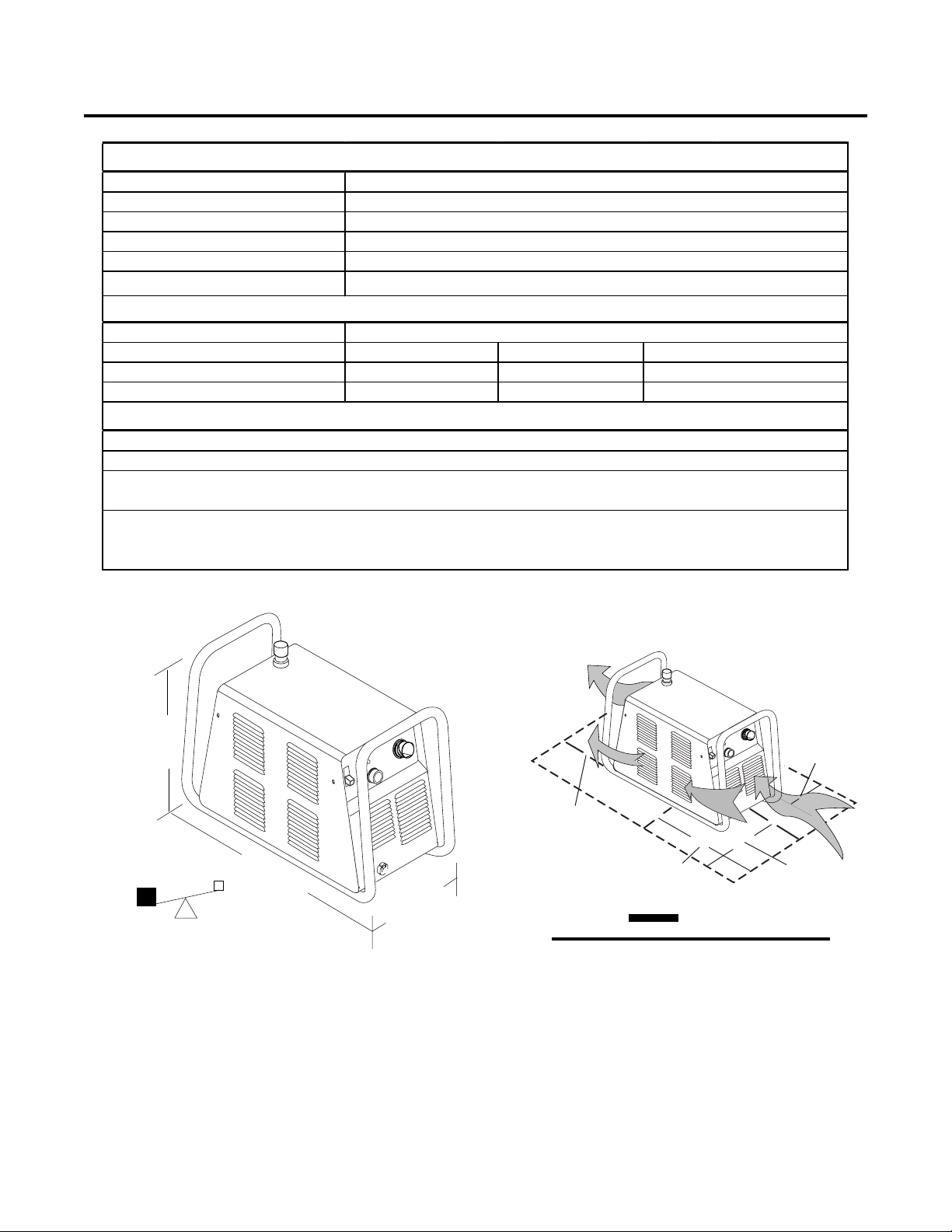
Firepower FP -38 Power Supply Specifications
Input Power (See Note 1)
Power Sensing
Input Power Cab l e
Output Current
Power Supply Gas Fi l tering Abili t y
Firepower FP -38 Power Supply Duty Cycle (Not e 3
Am bient Temperature
Duty Cy cle 35% 60%
DC Volt age 78 vdc 89 vdc
Current 30 Am ps 22 Am ps
. P ower s upply acc ept s 120-230 VAC input power. No manual switc hi ng i s required.
1
Plug m ust be replac ed for 208/230V i nput power.
2.
. Duty Cycle is the percentage of time the system can be operated without overheating. Dut y cy cle is
3
reduced if primary i nput voltage (AC) is l ow or the DC voltage is higher than s hown in this chart.
. A i r s uppl y m ust be free of oil, moi s ture, and other c ont am i nant s . Ex cess i ve oil and mois t ure may caus e
4
double-arcing, rapi d t ip wear, or even com plet e torch failure. Cont am i nant s m ay caus e poor c utting
performance and rapid electrode wear. Optional fil t ers provide increased fil t ering capabilit i es .
120 VA C (± 10%), Single-Phas e, 50/60 Hz
208 - 230 VAC (± 10%), S i ngle-P has e, 50/60 Hz
Automatic Voltage Selection. See Note 1.
Cable with pl ug, for 120VAC, 20-A m p S i ngle-P hase input power. (Note 2)
20-30 Amps, continuousl y variable
Part iculates to 20 Mic rons (Not e 4)
104° F (40° C)
n/a %
n/a vdc
n/a A m ps
Notes
A-03378
15.75"
400 mm
21"
0.53 m
43 lb / 19.5 kg
10"
254 mm
Weight includes torch & leads, input power cord,
and work cable with clamp.
150 mm
6"
150 mm
6"
150 mm
A-03379
6"
150 mm
CAUTION
Provide clearance for proper air flow through
the power supply. Operation without proper
air flow will inhibit proper cooling and reduce
duty cycle.
6"
Manual 0-2967 2-1 SPECIFICA TIONS
Page 12

Electrical Requirements
(Amps) F u se (Amps ) Wire (AWG) W ire (Canada)
F irepower FP -38 Input Power Requi rements
Suggest ed S izes (See Notes )
Input
Voltage Freq. (kVA)
(Volts) (Hz) 1-Ph 1-Ph 1-Ph 1-Ph 1-Ph
120 50 / 60
208 50 / 60
230 50 / 60
Refer to Local and National Codes or local authority having jurisdiction for proper wiring requirements.
Cable size is de-rated based on the Duty Cycle of the equipment.
The suggested sizes are based on flexible power cable with power plug installations.
Cable conductor temperature used is 167° F (75° C).
An energy limiting fuse UL Class RK-1 (examples: BUSS LPS/LPN-RK or Gould-Shawmut AZK-A6K) should be
used to minimize damage to Plasma Cutting, Welding or power distribution equipment.
NEVER use replaceable element fuses like UL Class H, or "one-time" fuses like UL Class K5.
Power Input Current Input
3.629351212
3.516201212
3.414201212
Line Voltages with Suggested Circuit Protecti on and Wire Sizes
Based on National Electri c Code and Canadian Electric Code
NOTES
Extension Cords
Extension cords must meet National Electric Code Guidelines (and OSHA Guidelines, where applicable). Extension
cords must have the same rating as the service and must have a three-pronged plug.
Options and Accessories
The following options is available for this Power Supply . Section 6 pr ovides catalog numbers and ordering information.
A. Single-Stage Air Filter Kit
A single-stage air filter for use on compressed air shop systems. Highly effective at removing moisture and
particulate matter from the air stream to at least 0.85 microns.
SPECIFICA TIONS 2-2 Manual 0-2967
Page 13

SECTION 3: INSTALLATION
3.1 Unpacking
1. Use the packing lists to identify and account for each item.
2. Inspect each item for possible shipping damage. If damage is evident, contact your distributor and / or shipping
company before proceeding with the installation.
3. Record Power Supply and Torch model and serial numbers, purchase date and vendor name, in the information
block at the front of this manual.
3.2 Lifting Options
The Power Supply includes a handle for hand lifting only. Be sure unit is lifted and transported safely and securely.
WARNINGS
Do not touch live electrical parts.
Disconnect input power cord before moving unit.
FALLING EQUIPMENT can cause serious personal injury and can damage equipment.
HANDLE is not for mechanical lifting.
• Only persons of adequate physical strength should lift the unit.
• Lift unit by the handles, using two hands. Do not use straps for lifting.
• Use optional cart or similar device of adequate capacity to move unit.
• Place unit on a proper skid and secure in place before transporting with a fork lift or other vehicle.
Manual 0-2967 3-1 INST ALLATION
Page 14
3.3 Primary Input Power Connections
CAUTION
Check your power source for correct voltage before plugging in or connecting the unit. The primary power sour ce,
fuse, and any extension cords used must conform to local electrical code and the recommended circuit pr otection and
wiring requirements as specified in Section 2.
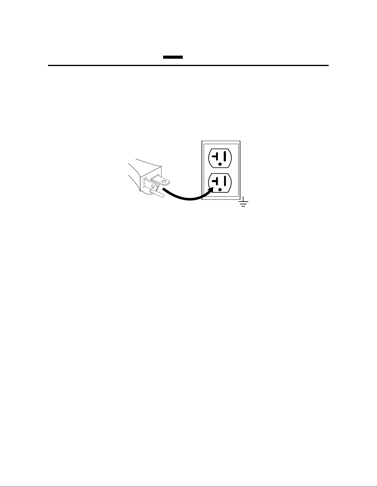
Power Cord and Plug
This power supply includes an input power cord and plug suitable for 120 VAC, 20 Amp, Single - Phase input
power .
A-03382
For 208 / 230 VAC input power, replace the supplied power plug. Use only an appr oved r eplacement input power
plug with ground.
Replace the plug as follows:
1. Cut the original cord close to the plug.
2. Strip back the outer cord cover as needed to connect the inner conductors to the replacement plug.
3. Connect conductors to the plug contacts according to the plug manufacturer's instr uctions. All three conductors
must be connected to the plug.
Connect the input power cord as follows:
1. Check the power source for correct voltage before plugging in the unit.
2. Connect the input power cable (or close the main disconnect switch) to supply power to the system.
120 V, 20A, 1Ø
INST ALLATION 3-2 Manual 0-2967
Page 15

3.4 Gas Connections
A. Connecting Gas Supply to Unit
The connection is the same for compressed air or high pressure gas cylinders. Refer to subsection 3.4-C if an optional
air line filter is to be installed.
1. Connect the gas line to the inlet port. The illustration shows typical fittings as an example.
NOTE
For a secure seal, apply thread sealant to the fitting threads, according to manufacturer's instructions. Do Not use
T eflon tape as a thr ead sealer , as small particles of the tape may break off and block the small gas passages in the torch.
Min. 1/4 inch
6.4 mm
A-03272
Gas Connection to Inlet Port
B. Check Air Quality
T o test the quality of air, put the RUN / SET switch in the SET (down) position, place a welding filter lens in front of
the torch and turn on the gas. Any oil or moistur e in the air will be visible on the lens. Do not start an arc!
A
26
24
22
A-03385
28
3020
Manual 0-2967 3-3 INST ALLATION
Page 16

C. Installing Optional Single - Stage Air Filter
An optional filter kit is recommended for improved filtering with compr essed air , to keep moisture and debris out of
the torch.
1. Attach the Single - Stage Filter Hose to the Inlet Port.
2. Attach the Filter Assembly to the filter hose.
3. Connect the gas line to the Filter. The illustration shows typical fittings as an example.
NOTE
For a secure seal, apply thread sealant to the fitting threads, according to the maker's instructions. Do Not use
T eflon tape as a thr ead sealer , as small particles of the tape may break off and block the small gas passages in the torch.
Connect as follows:
Filter Hose
Single-Stage
Filter Kit
No. 7-7507
Hose
Clamp
1/4 NPT
Hose Fitting
Gas Supply Hose
A-03281
Optional Single - Stage Filter Installation
INST ALLATION 3-4 Manual 0-2967
Page 17

D. Using High Pressure Gas Cylinders
When using high pressure gas cylinders as the gas supply:
1. Refer to the manufacturer’s specifications for installation and maintenance procedures for high pressure gas
regulators.
2. Examine the cylinder valves to be sure they are clean and fr ee of oil, gr ease or any foreign material. Briefly open
each cylinder valve to blow out any dust which may be present.
3. The cylinder must be equipped with an adjustable high - pressure r egulator capable of outlet pressur es up to 100
psi (6.9 bar) maximum and flows of at least 300 scfh (141.5 lpm).
4. Connect gas supply hose to the cylinder.
NOTE
Pressure should be set at 100 psi (6.9 bar) at the high pressure gas cylinder regulator.
Supply hose must be at least 1/4 inch (6 mm) I.D.
For a secure seal, apply thread sealant to the fitting threads, according to manufacturer's instructions. Do Not use
T eflon tape as a thr ead sealer , as small particles of the tape may break off and block the small gas passages in the torch.
Manual 0-2967 3-5 INST ALLATION
Page 18

3.5 Torch Connections
If necessary, connect the torch to the Power Supply. Connect only the model SL60 Torch to this power supply.
WARNING
Disconnect primary power at the source before connecting the torch.
1. Align the male connector (on the torch lead) with the female receptacle on the power supply. Press the
connector into the receptacle fully.
2. Turn the locking ring on the male connector fully clockwise until it clicks.
A-03380
Connecting the Torch to the Power Supply
3. The system is ready for operation.
1
2
INST ALLATION 3-6 Manual 0-2967
Page 19

4.01 Product Features
A. General Features
SECTION 4:
OPERATION
Handle and Leads WrapGas Pressure Knob
Torch Leads
Connector
Control Panel
Work Cable
and Clamp
A-03287
Manual 0-2967 4-1 OPERATION
Page 20

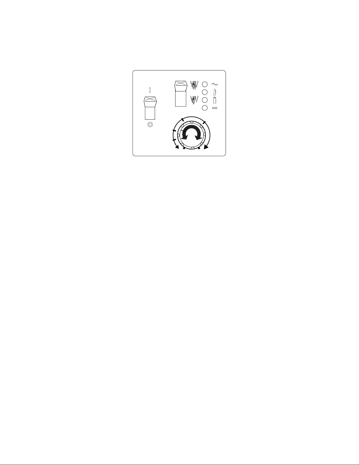
B. Control Panel
2
1
24
22
A
26
28
3020
A-03283
4
5
6
7
3
1. ON / OFF Switch
Controls input power to the power supply. Up is ON, down is OFF .
2. RUN / SET Switch
RUN (up) position is for general torch operation. SET (down) position is for setting gas pressure and purging
lines.
3. (A) Output Current Control
Sets the desired output current. If the overload protection (fuse or circuit breaker) on the input power circuit
opens frequently, either reduce cutting output, reduce the cutting time, or connect the unit to more adequate
input power . Refer to Section 2 for input power requirements.
4. AC Indicator
Steady light indicates power supply is r eady for operation. Blinking light indicates unit is in protective interlock
mode. Shut unit off, shut off or disconnect input power, correct the fault, and restart the unit. Refer to Section 5
for details.
5. TEMP Indicator
Indicator is normally OFF . Indicator is ON when internal temperature exceeds normal limits. Shut unit OFF; let
the unit cool before continuing operation.
6. GAS Indicator
Indicator is ON when adequate input gas pressure for power supply operation is present. Minimum pr essure for
power supply operation is below minimum for torch operation.
7. DC Indicator
Indicator is ON when DC output circuit is active.
OPERA TION 4-2 Manual 0-2967
Page 21

4.02 Preparations For Operating
At the start of each operating session:
WARNING
Disconnect primary power at the source before assembling or disassembling power supply , torch parts, or tor ch and
leads assemblies.
A. Torch Parts Selection
Check the torch for proper assembly and appropriate torch parts per the torch manual. The torch parts must
correspond with the type of operation, and with the amperage output of this Power Supply (30 amps maximum).
Use only genuine Firepower parts with this torch.
B. Torch Connection
Check that the torch is properly connected.
C. Check Primary Input Power Source
1. Check the power source for proper input voltage. Make sure the input power source meets the power requirements for the unit per Section 2, Specifications.
2. Connect the input power cable (or close the main disconnect switch) to supply power to the system.
D. Gas Selection
Ensure air source meets requir ements (refer to Section 2). Check connections and turn gas supply on.
E. Connect Work Cable
Clamp the work cable to the workpiece or cutting table. The area must be free fr om oil, paint and rust. Connect
only to the main part of the workpiece; do not connect to the part to be cut off.
A-03387
Manual 0-2967 4-3 OPERATION
Page 22

F. Power On
Place the Power Supply ON / OFF switch to the ON (up) position. AC indicator turns on. Gas indicator
turns on when there is sufficient gas pressure for power supply operation. Minimum pressure for power
supply operation is below the minimum for torch operation.
A
26
24
22
28
A-03384
3020
G. Set Operating Pressure
Place the Power Supply RUN / SET switch to the SET (down) position. Gas will flow . Adjust gas pressure to 65
psi / 4.5 bar.
1
2
65 psi / 4.5 bar
A
26
24
28
22
3020
A-03385
A-03389
OPERA TION 4-4 Manual 0-2967
Page 23
H. Select Current Output Level
Place RUN / SET switch to RUN (up) position. Gas flow will stop. Set the desired current output level.
A
26
24
22
A-03386
28
3020
I. Cutting Operation
Refer to Section 1, Important Safety Precautions. Wear heavy welding gloves and protective clothing. Protect
eyes with appropriate shielding. Refer to the torch manual for torch operation details.
J. Cutting Technique
Hold the torch with one or two hands, with the torch tip close to the workpiece. Do not cut or handle the
workpiece without welding gloves and protective clothing. Always wear pr otective eye shielding when cutting
or gouging. Move the torch along the cut line so the arc penetrates the workpiece and sparks emerge from the
bottom of the cut. Good cutting speeds create a slight trailing arc.
Manual 0-2967 4-5 OPERATION
Page 24

K. Typical Cutting Speeds
Cutting speeds vary according to torch output, the type of material being cut, and operator skill. Speeds shown
are typical for this cutting system using air plasma to cut mild steel, with output current at 30 amps and torch
held at 0 - 1/16" (0 - 1.6 mm) standoff.
MM
8
7
6
5
4
3
2
1
Inches
Meters
Inch
0.5
0.4
0.375
0.35
0.3
0.25
0.2
0.15
0.1
0.05
10
0.25
20
0.5401.00
60
1.5
Typical Cutting Speeds
Air Plasma on Mild Steel
100
120
80
2.5
2.0
Inches/ Meters per Minute
3.05
CUTTING SPEED
140
3.5
160
4.06
180
4.57
200
5.08
220
5.56
240
6.1
Gage
12.7
9.5
6
12
MATERIAL THICKNESS
18
20
24
A-03381
400
10.1
Output current setting or cutting speeds may be reduced to allow slower cutting when following a line, using a
template or cutting guide while still producing cuts of excellent quality.
L. Postflow
Release the trigger to stop the cutting arc. Gas continues to flow for approximately 10 seconds. During post flow, if the user moves the trigger release to the rear and presses the trigger, the pilot arc starts. The main arc
transfers to the workpiece if the torch tip is within transfer distance to the workpiece.
M. Shutdown
T urn the ON / OFF switch to OFF (down). All Power Supply indicators shut off. Unplug the input power cord
or disconnect input power. Power is removed from the system.
OPERA TION 4-6 Manual 0-2967
Page 25

4.03 Sequence of Operation
The following is a typical sequence of operation for this power supply. Refer to Appendix 1 for block diagram.
1. Plug the input power cord into an active circuit.
a. AC power is available at the Power Supply.
2. Place the ON / OFF switch on the Power Supply to ON (up) position.
a. AC indicator turns on; fan turns on: Gas indicator turns ON when ther e is sufficient gas pressur e
for power supply operation. Minimum pressure for power supply operation is below minimum for tor ch
operation.
NOTES
If there is adequate gas supply pressure to the power supply, gas comes on if Torch Trigger is pressed.
If torch trigger is held while user turns on main AC power, system goes into 'protective interlock' mode. AC
indicator flashes; torch will not pilot. Release torch trigger, turn AC switch OFF then ON.
3. Put RUN / SET switch to SET (down position).
a. Gas flows to set pressure . Turn gas pressure adjustment knob to set pressur e to 65 psi / 4.5 bar.
4. Put RUN / SET switch to RUN (up position). Gas flow stops.
5. Wear protective clothing and welding gloves. Protect eyes. Slide the trigger release to the rear; squeeze and
hold the trigger . Gas flows briefly, then shuts off momentarily. Then gas flow will resume. Pilot arc is established. DC indicator
turns ON. Move Torch within transfer distance of workpiece.
a. Main arc transfers to workpiece.
6. Complete cutting operation.
NOTE
If the torch is lifted from the workpiece while the torch switch is activated, the main ar c will stop and the pilot arc will
automatically restart.
7. Release the torch trigger.
a. Main arc stops; gas flows for approximately 10 seconds.
8. Set the power supply ON / OFF switch to OFF (down) position.
a. All indicators turn OFF; fan turns OFF.
9. Set the main power disconnect to OFF, or unplug input power cord.
a. Input power is removed fr om the system.
Manual 0-2967 4-7 OPERATION
Page 26

OPERA TION 4-8 Manual 0-2967
Page 27

5.01 General Maintenance
SECTION 5:
SERVICE
A. Each Use
Check torch consumables for wear , replace if necessary.
W ARNING
Shut off power before inspecting or removing torch parts.
Upper screws
B. Every three months
A. Check internal air filter , replace if necessary .
1. Shut off input power; turn off the gas supply. Bleed
down the gas supply.
2. Remove the upper cover screws.
3. Loosen the lower screws. Pull the cover up and
away from the unit.
NOTE
Leave internal ground wire in place.
Ground
wire
Upper screws
Lower screws
A-03285
Cover Removal
Manual 0-2967 5- 1 SERVICE
Page 28

4. Pull the upper end of the drain tube off the fitting on the filter bowl.
5. Unscrew the bowl. The filter element will be visible and still attached to the main body of the Regulator / Filter.
6. Unscrew the filter element from the Regulator / Filter body. The filter element will come off with a spool and some
additional pieces.
7. Note the correct assembly of the filter / spool then remove the filter from the spool and either clean it or replace it.
8. Screw the filter element and spool, with the baffle ring in place (teeth facing downward) back into the Regulator
body by compressing the spring on the spool. T ighten firmly by hand.
Ring
Replacement
Element
No. 9-4414
Spool
Bowl
A-03377
Regulator / Filter Element Replacement
9. Clean the inside of the bowl if necessary. Check that the knurled valve on the bottom of the bowl is fully open.
10. Reinstall the bowl. Reconnect the drain tube.
11. Reinstall the cover as follows:
a. Reconnect the ground wire, if necessary.
b. Set the cover onto the base so that it rests on the lower screws.
c. Tighten lower screws.
d. Reinstall and tighten the upper screws.
12. Turn on the air supply.
SERVICE 5-2 Manual 0-2967
Page 29

B. Check Optional Single - Stage Filter Element, replace if necessary .
1. Shut off input power .
2. Shut off air supply, bleed down system.
3. Disconnect gas supply hose from filter .
4. T urn the Cover counter - clockwise.
5. Remove the Filter Element from the Housing and set Element aside to dry.
6. W ipe inside of housing clean, then insert the replacement Filter Element open side first.
7. Replace Housing on Cover .
8. Reattach gas supply hose. If unit leaks between housing and cover , inspect the "O" Ring for cuts or other damage.
Housing
Filter
Element
(Cat. No. 9-7741)
Spring
O-ring
Cover
Barbed
Fitting
Assembled Filter
A-02476
Manual 0-2967 5- 3 SERVICE
Page 30

5.02 Common Faults
1. Insufficient Penetration
a. Cutting speed too fast
b. T or ch tilted too much
c. Metal too thick
d. Worn torch parts
e. Cutting current too low
f. Non - Genuine Firepower parts used
2. Main Arc Extinguishes
a. Cutting speed too slow
b. Torch standoff too high from workpiece
c. Cutting current too high
d. Work cable disconnected
e. Worn torch parts
f. Non - Genuine Firepower parts used
3. Excessive Dross Formation
a. Cutting speed too slow
b. Torch standoff too high from workpiece
c. Worn torch parts
d. Improper cutting current
e. Non - Genuine Firepower parts used
4. Short T orch Parts Life
a. Oil or moisture in air source
b. Exceeding system capability (material too thick)
c. Excessive pilot arc time
d. Gas pressure too low
e. Improperly assembled torch
f. Non - Genuine Firepower parts used
5. Difficult Starting
a. Worn torch parts
b. Non - Genuine Firepower parts used
SERVICE 5-4 Manual 0-2967
Page 31

5.03 Basic Troubleshooting Guide
W ARNING
There are extremely dangerous voltage and power levels present inside this unit. Do not attempt to diagnose or repair
unless you have had training in power electronics measurement and troubleshooting techniques.
A. Basic Troubleshooting: Overview
This guide covers basic troubleshooting. It is helpful for solving many of the common problems that can arise with this
system. If major complex subassemblies are faulty , the unit must be r eturned to an authorized service center for repair .
Follow all instructions as listed and complete each section in the order presented.
For major troubleshooting and parts replacement procedures refer to the Power Supply Service Manual for this prod-
uct.
B. How to Use This Guide
The following information will help the Customer / Operator determine the most likely causes for various symptoms.
Follow all instructions as listed and complete each section in the order presented.
This guide is set up in the following manner:
X. Symptom (Bold T ype)
Any Special Instructions
1. Cause
a. Check / Remedy
Locate your symptom, check the causes (easiest listed first), then remedies. Repair as needed being sure to verify that
unit operates properly after any repairs.
C. Common Symptoms
A. AC indicator OFF
1. Switch at customer's main power panel in OFF (open) position.
a. Close main power switch.
2. Power Supply ON / OFF switch in OFF position.
a. Turn switch to ON.
3. Customer's main power line fuse(s) or circuit breaker(s) blown
a. Check main power panel fuse(s) and replace as required.
4. Actual input voltage does not correspond to voltage of unit
a. Verify that the input line voltage is corr ect. Refer to Section 2, Input Wiring Requir ements.
5. Faulty components in unit
a. Return for repair or have qualified technician repair per Service Manual.
Manual 0-2967 5- 5 SERVICE
Page 32

B. AC indicator
1. System is in protective interlock mode. (User held torch trigger while turning on ON / OFF switch.)
a. Release torch trigger, set ON / OFF switch to OFF (down). Return ON / OFF switch to ON (up) position.
2. System is in protective interlock mode. (T orch parts are missing or loose.)
a. Release torch trigger, and set ON / OFF switch to OFF (down). Open main disconnect switch. Check tor ch
parts, including O - rings on torch head. Refer to illustration in Section 5.03-C-E. Replace parts as needed.
Reinstall shield cup; hand - tighten it securely against the torch head. Close main disconnect switch. Set ON
/ OFF switch to ON (up) position.
3. System is in protective interlock mode. (T orch connection to power supply is loose.)
a. Release torch trigger, and set ON / OFF switch to OFF (down). Tighten torch connector to receptacle on
power supply securely . Do not use tools. Set ON / OFF switch to ON (up).
4. System is in protective interlock mode. (User removed shield cup from torch while power supply ON / OFF switch was
ON.)
a. Release torch trigger, and set ON / OFF switch to OFF (down). Set ON / OFF switch to ON (up).
flashing; T orch cannot be activated
C. T orch will not pilot; AC indicator
1. Gas pressure below minimum for power supply operation
a. Set gas pressure to 65 psi / 4.5 bar
D. Torch will not pilot; AC indicator ON, Gas indicator ON (on system start-up); Gas indicator goes out
when user presses torch trigger
1. Gas pressure below minimum for torch operation
a. Set gas pressure to 65 psi / 4.5 bar
E. AC indicator flashing; T emp indicator flashing slowly
1. Fan disconnected or blocked.
a. Clear fan if blocked; let power supply cool off.
b. Connect wires to fan if necessary.
ON, Gas indicator OFF
SERVICE 5-6 Manual 0-2967
Page 33

F. AC indicator ON; TEMP indicator ON
1. Air flow blocked
a. Check for blocked air flow around the unit and correct condition.
2. Fan blocked
a. Check and correct condition.
3. Unit is overheated
a. Let unit cool down for at least 5 minutes. Make sure the unit has not been operated beyond Duty Cycle limit.
Refer to duty cycle data in Section 2.
4. Faulty components in unit
a. Return for repair or have qualified technician repair per Service Manual.
G. T orch will not pilot when torch switch is activated; AC indicator ON, TEMP indicator OFF, DC
indicator OFF
1. System is in SET mode
a. Release torch trigger. Change power supply RUN/SET switch to RUN (up) position.
2. Tor ch Head upper O-ring in wrong position.
a. Remove shield cup from torch. Check position of upper O-ring. Correct if necessary .
A-03640
Upper Groove
with V ent Holes
Must Remain Open
Upper O-Ring
in Correct Groove
Threads
Lower O-Ring
3. Faulty torch parts
a. Release torch trigger. Turn power supply OFF. Remove and inspect torch consumable parts. Replace if
necessary.
4. Gas pressure too high or too low
a. Adjust to proper pressure.
5. Faulty components in unit
a. Return for repair or have qualified technician repair per Service Manual.
Manual 0-2967 5- 7 SERVICE
Page 34

H. No cutting output; Torch activated; AC indicator
1. Work cable not connected to work piece, or connection is poor
a. Make sure that work cable has a proper connection to a clean, dry area of the workpiece.
2. Faulty components in unit
a. Return for repair or have qualified technician repair per Service Manual.
3. Faulty T orch
a. Return for repair or have qualified technician repair .
I. Low cutting output
1. Incorrect setting of CURRENT (A) control
a. Check and adjust to proper setting.
2. Faulty components in unit
a. Return for repair or have qualified technician repair .
J. Limited output with no control
1. Poor input or output connections
a. Check all input and output connections.
2. Work cable connection to work piece is poor
ON; Gas flows; Fan operates
a. Make sure that work cable has a proper connection to a clean, dry area of the workpiece.
3. Faulty components in unit
a. Return for repair or have qualified technician repair per Service Manual.
K. Erratic or improper cutting output
1. Poor input or output connections
a. Check all input and output connections.
2. Poor work cable connection
a. Make sure that work cable has a proper connection to a clean, dry area of the workpiece.
3. Fluctuations in input power
a. Have electrician check input line voltage.
L. Difficult Starting
1. Worn torch parts (consumables)
a. Shut off input power. Remove and inspect tor ch shield cup, tip, starter cartridge, and electrode. Replace
electrode or tip if worn; replace starter cartridge if end piece does not move freely; replace shield cup if
excessive spatter adheres to it.
SERVICE 5-8 Manual 0-2967
Page 35

M. Arc shuts off during operation; arc will not restart when torch switch is activated.
1. Power Supply is overheated (TEMP indicator
a. Let unit cool down for at least 5 minutes. Make sure the unit has not been operated beyond Duty Cycle limit.
Refer to Section 2 for duty cycle specifications.
2. Fan blades blocked (AC indicator
a. Check and clear blades.
3. Air flow obstructed (AC indicator
a. Check for obstructed air flow around the unit and correct condition.
4. Gas pressure too low (GAS indicator
a. Check source for at least 65 psi / 4.5 bar; adjust as needed.
5. Torch consumables worn
a. Check torch shield cup, tip, starter element, and electrode; replace as needed.
6. Faulty components in unit
a. Return for repair or have qualified technician repair per Service Manual.
N. No gas flow; AC indicator ON; Fan operates
flashing; TEMP indicator flashing slowly)
flashing; TEMP indicator ON)
OFF when torch switch is activated)
ON)
1. Gas not connected or pressure too low
a. Check gas connections. Adjust gas pressure to proper setting.
2. Shield Cup not properly installed.
a. Check to see that Shield Cup is properly installed.
3. Faulty components in unit
a. Return for repair or have qualified technician repair.
O. Torch cuts but not adequately
1. Current (A) control set too low
a. Increase current setting.
2. T orch is being moved too fast across workpiece
a. Reduce cutting speed.
3. Excessive oil or moisture in torch
a. Hold torch 1/8 inch (3 mm) from clean surface while purging and observe oil or moisture buildup (do not
activate torch). If there are contaminants in the gas, additional filtering may be needed.
Manual 0-2967 5- 9 SERVICE
Page 36

SERVICE 5-10 Manual 0-2967
Page 37

SECTION 6:
PARTS LISTS
6.01 Introduction
A. Parts List Breakdown
The parts list provides a breakdown of all replaceable components.
B. Returns
If a product must be returned for service, contact your distributor . Materials r eturned without pr oper authorization
will not be accepted.
6.02 Ordering Information
Order replacement parts by catalog number and complete description of the part or assembly, as listed in the parts
list for each type item. Also include the model and serial number of the torch. Address all inquiries to your authorized distributor .
6.03 Replacement Assemblies
The following items are included with the replacement power supply: input power cord and plug, work cable &
clamp, gas pressure regulator / filter, and operating manual.
Qty Description Catalog #
1 Firepower FP-38 Power Supply with input power cord 1445-0084
and 120 VAC, 20A plug
6.04 Power Supply Replacement Parts
Qty Description Catalog #
1 Replacement Filter Element 9-4414
Manual 0-2967 6-1 P A RTS LISTS
Page 38

6.05 Options and Accessories
Qty Description Catalog #
1 Multi-Purpose Cart (Not Shown) 1445-0913
1 Single - Stage Filter Kit (includes Filter & Hose) 1445-0080
1 Replacement Filter Body 9-7740
1 Replacement Filter Hose (not shown) 9-7742
2 Replacement Filter Element 9-7741
Housing
Filter
Element
(Cat. No. 9-7741)
Spring
O-ring
Cover
Barbed
Fitting
Assembled Filter
Single - Stage Air Filter
A-02476
PARTS LISTS 6-2 Manual 0-2967
Page 39

APPENDIX 1: SEQUENCE OF OPERATION
(BLOCK DIAGRAM)
ACTION
Close external
disconnect switch.
RESULT
Power to system.
ACTION
ON / OFF switch
to ON.
RESULT
AC indicator ON.
Fan on.
Power circuit ready.
ACTION
Protect eyes and
activate torch.
RESULT
Gas flows briefly,
then stops.
Gas restarts.
DC indicator on.
Pilot arc established.
ACTION
Release torch trigger.
RESULT
Main arc stops.
Gas flow stops after post - flow.
ACTION
RUN / SET switch to SET.
RESULT
Gas flows to set pressure.
GAS indicator on when input
pressure is adequate.
PILOT ARC
ON / OFF switch
All indicators off.
Power supply fan shuts off.
ACTION
to OFF
RESULT
ACTION
RUN / SET switch
to RUN.
RESULT
Gas flow stops.
Torch moved away
from work (while
still activated).
Main arc stops.
Pilot arc automatically
Torch moved within
transfer distance of workpiece.
Main arc transfers.
Pilot arc off.
Connect work cable
Set output amperage
ACTION
RESULT
restarts.
ACTION
RESULT
ACTION
Unplug input
power cord or
open external
disconnect.
RESULT
No power to system.
ACTION
to workpiece.
RESULT
System is ready
for operation.
A-03299
Manual 0-2967 A-1 APPENDIX
Page 40

APPENDIX 2: DATA TAG INFORMATION
Type of Power
Supply (Note 1)
Plasma Cutting
Symbol
Input Power
Symbol
Input Power
Specifications
(Phase, AC or DC
Hertz Rating)
Model:
1/3
Rated NoLoad V oltage
Degree of Protection
f
1
f
2
Output Current Type
U
0
X
I
=
U
2
Conventional
Load V oltage
U
1
Rated Supply
Voltage (Note 2)
West Lebanon, NH USA 03784
S/N
Made in USA
Duty Cycle Factor
Rated Maximum
Supply Current
1max 1eff
1
1Ø
I
3Ø
1
Manufacturer's Name and/or
Logo, Location, Model and
Revision Level, Serial Number
and Production Code
Regulatory Standard Covering
This Type of Power Supply
Output Range (Amperage/
Voltage)
Duty Cycle Data (Note 3)
I
3Ø1Ø
Maximum Effective
Supply Current
Manufacturer's Electrical
Schematic File Number
and Revision Level
NOTES:
1. Symbol shown indicates single- or three-phase AC input,
static frequency converter-transformer-rectifier, DC output.
2. Indicates input voltages for this power supply. Most power
supplies carry a label at the input power cord showing input
voltage requirements for the power supply as built.
3. Top row: Duty cycle values.
Second row: Rated cutting current values.
Third row: Conventional load voltage values.
NOTE
Sections of the data tag may be applied in
separate locations on the Power Supply.
Standard Symbols
AC
DC
Phase
Ø
A-03288
APPENDIX A-2 Manual 0-2967
Page 41

This page left blank.
Manual 0-2967 A-3 APPENDIX
Page 42

APPENDIX 3: SYSTEM SCHEMATIC
A
120/208/230V
INPUT
50/60HZ
B
C
D
1
INPUT 230V ONLY
EMC
FILTER
CE ONLY
CURRENT ADJUST
SW2
CHASSIS GND
M1
FAN1
CURRENT
CONTROL
20 - 30
SET
RUN
NORMALLY CLOSED
OVER-TEMP
PRESSURE SW
L1
SW1
SW1
STUD
+
12VDC
TS1
PS1
(E1)
(E2)
RED
BLACK
CW
(10)
(11)
2
E1
E2
E13
P4
P6
(5)
(6)
(7)
P2
(8)
(9)
P5
P9 J9
3
J7
TEST
1
4
E12A
K1
(E14A)
BR1
1
4
E14A
(E16A)
FILTERING
J4
1
1
2
2
J6
1
1
2
2
3
3
J2
1
1
2
323
J5
1
1
2
2
ZERO
1
1
2
2
3
3
E15A
E16A
E12B
(E14B)
E14B
(E16B)
E15B
E16B
PANEL INDICATOR
AC
TEMP
GAS
DC
D7
D13
D16
D19
123
BR2
4
E11
(E12A)
2
(E15A)
3
-+
(E12B)
(E15B)
-+
4
PFC INDUCTOR
T1
Q7
LOGIC AND CONTROL
TEST POINTS:
TP1 LOGIC COMMON
TP2 SHORT TO TP23 TO DISABLE BIAS SUPPLY
TP6 SHORT TO TP24 TO DISABLE POWER
TP8 SHORT TO TP26 TO DISABLE SHORTED
CAUTION: SOME PORTIONS OF THE CONTROL/
LOGIC CIRCUITRY ARE CONNECTED TO THE
INPUT LINE. CONNECTION TO A GROUNDED
INSTRUMENT COULD CAUSE A SHOCK
HAZARD OR DESTROY THE POWER SUPPLY.
ACCESS BY AN AUTHORIZED TECHNICIAN ONLY.
MAIN PCB ASSEMBLY
19X1773
E18
D47
Q8
BIAS
CONVERTER
CIRCUITRY
FACTOR CORRECTION
TORCH PROTECTION
E
F
A-03405
1
2
3
4
APPENDIX A-4 Manual 0-2967
Page 43

5
C70, 72, 81
C71, 73, 75
D56
TORCH SWITCH ON
Q13
Q12
+14VA
+12VB
6
E5
D55
BGND
PWM ON
E6
AGND
o
PRI
D22
D99
MAIN
T3
SEC
o
E10
7
D53
E9
E20
OUTPUT INDUCTOR
L1
D54
Q11
8
E4
(E4)
9
P8J8
10
A
TORCH
(-)
T
O
R
C
TORCH
SWITCH
H
B
WORK
E8
(E8)
J3
P3
(12)
1
1
4
(13)
22
3
(14)
3
2
3
(15)
1
44
PILOT
4
3
2
1
PIP
5
QUICK DISCONNECT
E19
WORK
C
J1
P1
1
1
2
2
SOL1
B
A
GAS SOLENOID
D
COMP DESCRIPTION
TS1
OVER-TEMP. SENSOR
M1 FAN, 4.5" 12VDC
PS1 PRESSURE SWITCH
SOL1 GAS SOLENOID
T1
T3
PFC INDUCTOR
MAIN TRANSFORMER
L1 OUTPUT INDUCTOR
SW1
SW2
AA
AB
Last Modified:
5
6
7
REL ECO 100213
REL ECO 100333
REL ECO 100535
A
C
SWITCH, ON/OFF
SWITCH, RUN/SET
GCW
GCW
DAT
Thursday, March 20, 2003
8
DateByRevisionsRev
7/29/02
10/04/02
2/27/03
15:05:29
LOCATION
D2
C1
D1
D9
A4
A7
A8
B2
D1
THERMAL DYNAMICS
INDUSTRIAL PARK No. 2
WEST LEBANON, NH 03784
Information Proprietary to THERMAL DYNAMICS CORPORATION.
Not For Release, Reproduction, or Distribution without Written Consent.
NOTE:
Unless Otherwise Specified, Resistors are in Ohms 1/4W 5%.
Capacitors are in Microfarads (UF)
TITLE:
CM38 12 0/208/230V SINGL E PHASE 5 0 / 6 0 H z
SCHEMATIC,
603-298-5711
9
PCB No:
Assy No:
SupersedesScale
Date:
Tuesday, May 15, 2001
Drawn: References
GCW
Chk: App:
Size
C
DWG No:
42X1089
10
Sheet
11
A-03405
E
F
of
Manual 0-2967 A-5 APPENDIX
Page 44

APPENDIX A-6 Manual 0-2967
 Loading...