

Page 1
Plasma Cutting System
Model FP- 35A
Number the art as Art # A-044??
Art # A-04502
Operating Manual
January 23, 2006 Manual 0-4681
Page 2

Page 3

TABLE OF CONTENTS
SECTION 1:
GENERAL INFORMATION ................................................................................................ 1-1
1.01 Notes, Cautions and Warnings ...................................................................... 1-1
1.02 Important Safety Precautions ....................................................................... 1-1
1.03 Publications .................................................................................................. 1-2
1.04 Statement of Warranty .................................................................................. 1-4
SECTION 2:
INTRODUCTION ............................................................................................................... 2-1
2.01 Overview ...................................................................................................... 2-1
2.02 General Specifications .................................................................................. 2-1
2.03 Features ....................................................................................................... 2-1
2.04 Torch Specifications ..................................................................................... 2-2
2.05 System Contents .......................................................................................... 2-2
2.06 Transporting Methods ................................................................................... 2-2
SECTION 3:
INSTALLATION .................................................................................................................. 3-1
3.01 Site Selection ............................................................................................... 3-1
3.02 Electrical Input Connections ......................................................................... 3-1
3.03 Compressed Air Connection ......................................................................... 3-1
SECTION 4:
OPERATION ...................................................................................................................... 4-1
4.01 Front Control Panel ....................................................................................... 4-1
4.02 Preparations For Operating ........................................................................... 4-2
SECTION 5:
SERVICE .......................................................................................................................... 5-1
5.01 General Maintenance .................................................................................... 5-1
5.02 Basic Troubleshooting Guide ......................................................................... 5-1
5.03 Contact information ...................................................................................... 5-3
Appendix 1: Operating Sequence, Block Diagram ..................................................................... A-1
Appendix 2: Torch Connection ................................................................................................... A-2
Appendix 3: Microchip Pin-Out .................................................................................................. A-3
Appendix 4: Replacement Hand Torch Parts List ....................................................................... A-4
Appendix 5: System Schematic ................................................................................................ A-6
Page 4

Page 5
SECTION 1:
GENERAL INFORMATION
1.01 Notes, Cautions and Warnings
Throughout this manual, notes, cautions, and warnings
are used to highlight important information. These highlights are categorized as follows:
NOTE
An operation, procedure, or background information which requires additional emphasis or is helpful in efficient operation of the system.
CAUTION
A procedure which, if not properly followed, may
cause damage to the equipment.
WARNING
A procedure which, if not properly followed, may
cause injury to the operator or others in the operating area.
1.02 Important Safety Precautions
WARNINGS
OPERATION AND MAINTENANCE OF
PLASMA ARC EQUIPMENT CAN BE DANGEROUS AND HAZARDOUS TO YOUR
HEALTH.
Plasma arc cutting produces intense electric and
magnetic emissions that may interfere with the
proper function of cardiac pacemakers, hearing aids,
or other electronic health equipment. Persons who
work near plasma arc cutting applications should
consult their medical health professional and the
manufacturer of the health equipment to determine
whether a hazard exists.
To prevent possible injury, read, understand and
follow all warnings, safety precautions and instructions before using the equipment. Call 1-603-2985711 or your local distributor if you have any questions.
GASES AND FUMES
Gases and fumes produced during the plasma cutting
process can be dangerous and hazardous to your health.
• Keep all fumes and gases from the breathing area.
Keep your head out of the welding fume plume.
• Use an air-supplied respirator if ventilation is not
adequate to remove all fumes and gases.
• The kinds of fumes and gases from the plasma arc
depend on the kind of metal being used, coatings
on the metal, and the different processes. You must
be very careful when cutting or welding any metals which may contain one or more of the following:
Antimony Chromium Mercury
Arsenic Cobalt Nickel
Barium Copper Selenium
Beryllium Lead Silver
Cadmium Manganese Vanadium
• Always read the Material Safety Data Sheets
(MSDS) that should be supplied with the material
you are using. These MSDSs will give you the information regarding the kind and amount of fumes
and gases that may be dangerous to your health.
• For information on how to test for fumes and gases
in your workplace, refer to item 1 in Subsection 1.03,
Publications in this manual.
• Use special equipment, such as water or down draft
cutting tables, to capture fumes and gases.
• Do not use the plasma torch in an area where combustible or explosive gases or materials are located.
• Phosgene, a toxic gas, is generated from the vapors
of chlorinated solvents and cleansers. Remove all
sources of these vapors.
• This product, when used for welding or cutting, produces fumes or gases which contain chemicals
known to the State of California to cause birth defects and, in some cases, cancer. (California Health
& Safety Code Sec. 25249.5 et seq.)
ELECTRIC SHOCK
Electric Shock can injure or kill. The plasma arc process
uses and produces high voltage electrical energy. This
electric energy can cause severe or fatal shock to the operator or others in the workplace.
January 23, 2006 1-1 GENERAL INFORMATION
Page 6
• Never touch any parts that are electrically “live” or
“hot.”
• Wear dry gloves and clothing. Insulate yourself from
the work piece or other parts of the welding circuit.
• Repair or replace all worn or damaged parts.
• Extra care must be taken when the workplace is moist
or damp.
• Install and maintain equipment according to NEC
code, refer to item 9 in Subsection 1.03, Publications.
• Disconnect power source before performing any service or repairs.
• Read and follow all the instructions in the Operating Manual.
FIRE AND EXPLOSION
Fire and explosion can be caused by hot slag, sparks, or
the plasma arc.
• Be sure there is no combustible or flammable material in the workplace. Any material that cannot be
removed must be protected.
• Ventilate all flammable or explosive vapors from
the workplace.
• Do not cut or weld on containers that may have held
combustibles.
• Provide a fire watch when working in an area where
fire hazards may exist.
• Hydrogen gas may be formed and trapped under
aluminum workpieces when they are cut underwater or while using a water table. DO NOT cut alu-
minum alloys underwater or on a water table unless the hydrogen gas can be eliminated or dissipated.
Trapped hydrogen gas that is ignited will cause an
explosion.
PLASMA ARC RAYS
Plasma Arc Rays can injure your eyes and burn your skin.
The plasma arc process produces very bright ultra violet
and infra red light. These arc rays will damage your eyes
and burn your skin if you are not properly protected.
• To protect your eyes, always wear a welding helmet or shield. Also always wear safety glasses with
side shields, goggles or other protective eye wear.
• Wear welding gloves and suitable clothing to protect your skin from the arc rays and sparks.
• Keep helmet and safety glasses in good condition.
Replace lenses when cracked, chipped or dirty.
• Protect others in the work area from the arc rays.
Use protective booths, screens or shields.
• Use the shade of lens as suggested in the following
per ANSI/ASC Z49.1:
Minimum Protective Suggested
Arc Current Shade No. Shade No.
Less Than 300* 8 9
300 - 400* 9 12
400 - 800* 10 14
* These values apply where the actual arc is clearly
seen. Experience has shown that lighter filters may
be used when the arc is hidden by the workpiece.
1.03 Publications
Refer to the following standards or their latest revisions
for more information:
1. OSHA, SAFETY AND HEALTH STANDARDS, 29CFR
1910, obtainable from the Superintendent of Documents,
U.S. Government Printing Office, Washington, D.C.
20402
NOISE
2. ANSI Standard Z49.1, SAFETY IN WELDING AND
CUTTING, obtainable from the American Welding Society, 550 N.W. LeJeune Rd, Miami, FL 33126
Noise can cause permanent hearing loss. Plasma arc processes can cause noise levels to exceed safe limits. You
must protect your ears from loud noise to prevent permanent loss of hearing.
• To protect your hearing from loud noise, wear protective ear plugs and/or ear muffs. Protect others
in the workplace.
• Noise levels should be measured to be sure the decibels (sound) do not exceed safe levels.
• For information on how to test for noise, see item 1
in Subsection 1.03, Publications, in this manual.
3. NIOSH, SAFETY AND HEALTH IN ARC WELDING
AND GAS WELDING AND CUTTING, obtainable from
the Superintendent of Documents, U.S. Government
Printing Office, Washington, D.C. 20402
4. ANSI Standard Z87.1, SAFE PRACTICES FOR OCCUPATION AND EDUCATIONAL EYE AND FACE PROTECTION, obtainable from American National Standards Institute, 1430 Broadway, New York, NY 10018
5. ANSI Standard Z41.1, STANDARD FOR MEN’S
SAFETY-TOE FOOTWEAR, obtainable from the American National Standards Institute, 1430 Broadway, New
York, NY 10018
GENERAL INFORMATION 1-2 January 23, 2006
Page 7

6. ANSI Standard Z49.2, FIRE PREVENTION IN THE
USE OF CUTTING AND WELDING PROCESSES, obtainable from American National Standards Institute,
1430 Broadway, New York, NY 10018
7. AWS Standard A6.0, WELDING AND CUTTING
CONTAINERS WHICH HAVE HELD COMBUSTIBLES, obtainable from American Welding Society,
550 N.W. LeJeune Rd, Miami, FL 33126
8. NFPA Standard 51, OXYGEN-FUEL GAS SYSTEMS
FOR WELDING, CUTTING AND ALLIED PROCESSES, obtainable from the National Fire Protection
Association, Batterymarch Park, Quincy, MA 02269
9. NFPA Standard 70, NATIONAL ELECTRICAL CODE,
obtainable from the National Fire Protection Association, Batterymarch Park, Quincy, MA 02269
10. NFPA Standard 51B, CUTTING AND WELDING PROCESSES, obtainable from the National Fire Protection
Association, Batterymarch Park, Quincy, MA 02269
11. CGA Pamphlet P-1, SAFE HANDLING OF COMPRESSED GASES IN CYLINDERS, obtainable from the
Compressed Gas Association, 1235 Jefferson Davis
Highway, Suite 501, Arlington, VA 22202
12. CSA Standard W117.2, CODE FOR SAFETY IN WELDING AND CUTTING, obtainable from the Canadian
Standards Association, Standards Sales, 178 Rexdale
Boulevard, Rexdale, Ontario, Canada M9W 1R3
13. NWSA booklet, WELDING SAFETY BIBLIOGRAPHY
obtainable from the National Welding Supply Association, 1900 Arch Street, Philadelphia, PA 19103
14. American Welding Society Standard AWSF4.1, RECOMMENDED SAFE PRACTICES FOR THE PREPARATION FOR WELDING AND CUTTING OF CONTAINERS AND PIPING THAT HAVE HELD HAZARDOUS
SUBSTANCES, obtainable from the American Welding
Society, 550 N.W. LeJeune Rd, Miami, FL 33126
15. ANSI Standard Z88.2, PRACTICE FOR RESPIRATORY
PROTECTION, obtainable from American National
Standards Institute, 1430 Broadway, New York, NY
10018
January 23, 2006 1-3 GENERAL INFORMATION
Page 8

1.04 Statement of Warranty
LIMITED WARRANTY: Subject to the terms and conditions established below, Thermadyne® Corporation warrants to the original retail
purchaser that new Thermadyne CutSkill Series plasma cutting systems sold after the effective date of this warranty are free of defects in
material and workmanship. Should any failure to conform to this warranty appear within the applicable period stated below, Thermadyne
Corporation shall, upon notification thereof and substantiation that the product has been stored operated and maintained in accordance
with Thermadynes’ specifications, instructions, recommendations and recognized industry practice, correct such defects by suitable repair
or replacement.
This warranty is exclusive and in lieu of any warranty of merchantability or fitness for a particular purpose.
Thermadyne will repair or replace, at its discretion, any warranted parts or components that fail due to defects in material or workmanship
within the time periods set out below. Thermadyne Corporation must be notified within 30 days of any failure, at which time Thermadyne
Corporation will provide instructions on the warranty procedures to be implemented.
Thermadyne Corporation will honor warranty claims submitted within the warranty periods listed below. All warranty periods begin on the
date of sale of the product to the original retail customer /Purchaser.
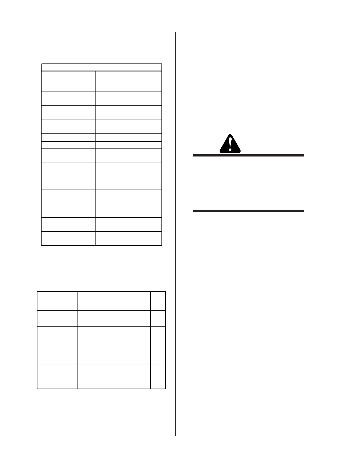
LIMITED WARRANTY PERIOD
Product
Power Supply Components
(Parts and Labor)
Torch and Leads
(Parts and Labor)
FP-20A 1 Year 1 Year
FP-35A 1 Year 1 Year
FP-70A 1 Year 1 Year
FP-100A 1 Year 1 Year
This warranty does not apply to:
1. Consumable Parts, such as tips, electrodes, shield cups, o - rings, starter cartridges, gas distributors, fuses, filters.
2. Equipment that has been modified by an unauthorized party, improperly installed, improperly operated or misused
based upon industry standards.
In the event of a claim under this warranty, the remedies shall be, at the discretion of Thermadyne Corporation:
1. Repair of the defective product.
2. Replacement of the defective product.
3. Reimbursement of reasonable costs of repair when authorized in advance by Thermadyne.
4. Payment of credit up to the purchase price less reasonable depreciation based on actual use.
These remedies may be authorized by Thermadyne and are FOB West Lebanon, NH or an authorized Thermadyne service station. Product
returned for service is at the owner’s expense and no reimbursement of travel or transportation is authorized.
LIMITATION OF LIABILITY: Thermadyne Corporation shall not under any circumstances be liable for special or consequential damages
such as, but not limited to, damage or loss of purchased or replacement goods or claims of customer of distributors (hereinafter “Purchaser”)
for service interruption. The remedies of the Purchaser set forth herein are exclusive and the liability of Thermadyne with respect to any
contract, or anything done in connection therewith such as the performance or breach thereof, or from the manufacture, sale, delivery, resale,
or use of the goods covered by or furnished by Thermadyne whether arising out of contract, negligence, strict tort, or under any warranty,
or otherwise, shall not, except as expressly provided herein, exceed the price of the goods upon which liability is based.
This warranty becomes invalid if replacement parts or accessories are used which may impair the safety or performance of any
Thermadyne product.
This warranty is invalid if the Thermadyne product is sold by non - authorized persons.
Effective January 25, 2005
GENERAL INFORMATION 1-4 January 23, 2006
Page 9
SECTION 2:
g
y
g
g
g
INTRODUCTION
35A
CUT
OFF
2.01 Overview
Plasma is a gas which has been heated to an extremely
high temperature and ionized so that it becomes electrically conductive. The plasma arc cutting process uses
this plasma to transfer an electrical arc to the workpiece. The metal to be cut is melted by the heat of the
arc and then blown away.
2.02 General Specifications
System Des criptions FP-35A
Maximum Output 35 Amps
Input Voltage & Phase
Frequenc
Input Power 7.4 kVA
Current Input Fus e 20 Amps
No Load Volta
Load Volta
Output Current 15-35 Amps
Post Flow Time 10 Seconds
Operating Air Pressure
Maximum Air Pressure
Air Flow
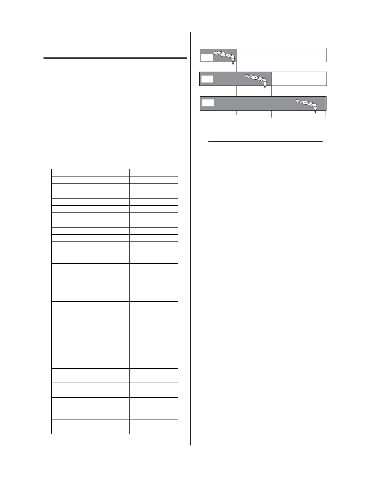
System *Duty Cycle ratings
at Ambient Air Temperatures
of 40° C / 104° F.
System *Duty Cycle ratings
at Ambient Air Temperatures
of 40° C / 104° F.
System *Duty Cycle ratings
at Ambient Air Temperatures
of 40° C / 104° F.
Genuine Cutting Capacity
@ 35A
Maximum Cutting Capacity
@ 35A
Dimens ion (W x D x H)
Net Weight
e220V
e94V
230V,
le Phase
Sin
50/60Hz
75 psi (5.2
bar)(.52 MPa)
125 psi (8.6
bar)(.86 Mpa)
400 scfh
6.6 scfm
(188.7 lpm)
35% @ 35Amps
60% @ 27Amps
100% @ 20Amps
3/8" (10mm)
1/2" (12mm)
8.3"x20"x14.8"
(210 mm x 510
mm x 350 mm )
44 lbs.
)
(20k
CUT
27A
CUT
20A
35% (3.5 min)
60% (6 min)
OFF
100% (10 min)
NOTE:
*Duty Cycle is the percentage of time the system can be operated without overheating. Duty
cycle is reduced if primary input voltage (AC) is
low or the DC voltage is higher than shown in
previous chart.
2.03 Features
• PORTABLE - Weighing just 44 lbs., (20 kg) it is
easily moved from location to location.
• POWERFUL CUTTING PERFORMANCE Genuine cutting capacity is 3/8” (10mm) and
1/2” (12mm) for maximum cut.
• CUTS MOST METALS - Useful for most metals
such as stainless steel, aluminum, mild steel, copper and alloys.
• NO HIGH FREQUENCY - Starts without highfrequency so it won’t interfere with controls or
computers.
• MORE TORCH, LESS MONEY - The SL60™
1Torch™ provides state of the art technology and
performance of more expensive torches.
5
Art # A-0450
Manual 0-4681 2-1 Introduction
Page 10
2.04 Torch Specifications
g
p
y
y
g
y
If you have questions or concerns regarding your system, please contact:
Thermal Dynamics Technical Service Dept.
SL60™ 1Torch™ Ratin
Torch Configuration
Torch Leads Len
Am bient
Temperature
Torch Duty Cycle
Maximum Current
Voltage (V
Arc Striking Voltage 7kV
Type of Cooling
Parts-in-Place:
Gas Requirement:
Input
Gas Pressure
Minimum Gas Flow
Plasma Power
Suppl
)500V
eak
Used With:
Torch Head at 75° to
Torch Handle
th 20 feet ( 6.1 m)
104° F
40° C
100% @ 60 Amps
@ 400 scfh
60 Amps, DC,
Straight Polarity
Ambient air and gas
st ream through torch
Built-in Switch
in Torch Head
Single Gas, Compressed
Air Onl
75 ps i (5.2 bar)(.52MPa) 125 psi (8.6 bar)(.86M Pa)
400 scfh / 6.6 scfm
(188.7 lpm)
FP-35A
s for FP-35A
Tel: 1-800-752-7622 (1-800-PLASMA2)
Fax: 1-800-221-4401
e-mail address: tdc-tech@thermadyne.com
2.06 Transporting Methods
Lift unit with handle on top of case. Use handcart or
similar device of adequate capacity for transporting.
WARNINGS
ELECTRIC SHOCK can kill. DO NOT
TOUCH live electrical parts. Disconnect input
power from supply before moving the power
source.
FALLING EQUIPMENT can cause serious personal injury and equipment damage.
2.05 System Contents
ITEMS Description Q't
Power Source Model FP-35A 1
Torch Set
Added
Features
Input Power
Cable
SL 60™, with 20' (6.1m)
leads
Air Regulator
Work Cable
Manual
Torch Electrodes
Torch Tips
3 Meter NEMA 10 AWG /
2
4.8 mm
with 6 - 50 P
molded plug
1
1
1
1
2
3
1
Introduction 2-2 Manual 0-4681
Page 11

SECTION 3:
3.03 Compressed Air Connection
INSTALLATION
3.01 Site Selection
• Place in a clean and dry area.
• Provide adequate ventilation and fresh air supply.
• Ideal ambient temperature should not exceed
40°C / 104°F. Temperatures exceeding that may
diminish cutting capacity or quality.
• The cutting machine must be placed on an even,
firm surface so that it stands firmly.
3.02 Electrical Input Connections
• Input voltage is 230V ± 10%, 50/60 Hz single
phase.
CAUTION
Check your power source for correct voltage before plugging in or connecting the unit. The
primary power source, fuse, and any extension
cords used must conform to local electrical code
and the recommended circuit protection and wiring requirements as specified in Section 2.0.
• An air compressor is required and should be connected to rear panel of power source by air hose.
• Air pressure should be 75 psi (5.2 bar) (.52MPa)
and air should be dry and clean.
• Air flow should be 400 scfh / 6.6 scfm (188.7 lpm)
minimum.
Connect
Air Here
Input
Power
Art # A-04485
DANGER
Do not cut in humid or wet surroundings.
• Before you maintain or replace torch parts, wait
for the post flow air cycle (approximately 10 seconds), to stop, then turn the machine off.
• Always use original manufacturers parts. The use
of aftermarket parts could result in shorter parts
life and in unsatisfactory cutting results. Any warranty claims would be waived.
NOTE
Repairs must be done by skilled and qualified
personnel only.
Manual 0-4681 3-1 Installation
Page 12

Installation 3-2 Manual 0-4681
Page 13

SECTION 4:
OPERATION
B. Buttons
• Torch Switch Latch Button
4.01 Front Control Panel
Overheating
Indicator
"On / Off"
Switch
AC Power
Indicator
Air Vents
Work Lead
Connection
A. Indicator Lamp
• Power Indicator
Lights when primary power switch is turned
on.
• TEMPERATURE Indicator
Air Error Indicator
I
35A
O
Art # A-04386
1
7
8
1
1
6
9
1
14
2
5
1
0
1
6
2
4
12
1
1
2
3
2
1
1
8
0
2
1
3
12
2
2
4
0
8
11
2
0
5
115VAC
1
230VAC
A
Torch Switch
Latch Indicator
Torch Switch
Latch Button
Air Set
Button
Current
Control Knob
Torch
Connection
For continuous cutting performance. Depress
this button ( turn “On” ) while cutting with the
torch. Release the torch trigger and the torch
will continue to cut without depressing the torch
trigger.
• Air Set Button
To adjust air pressure and to cool down heated
torch.
Art # A-04503
Air will flow from gap
next to shield cup.
C. Main Current Control Knob
To adjust cutting current. Turning clockwise increases the cutting current and counter clockwise decreases the cutting current.
Indicator is normally OFF. Indicator is ON
when internal temperature exceeds normal
limits.
• Air Error Indicator
This indicator lights and is accompanied by an
intermittent audible tone when there is not
enough air pressure to operate the power supply. Indicator is normally off.
NOTE
It is possible to have enough air pressure to operate the power supply but not enough air flow
to operate the torch.
• Torch Switch Latch Indicator
This indicator lights when the Torch Switch
Latch Button has been pressed for continuous
cutting.
20
25
15
10
Art # A-04387
35
D. Primary Power Switch, ON / OFF
The power switch is located on the front panel.
Placing the primary power switch to the “ON”
position energizes the power source and activates the Power Indicator.
WARNING
When the power source is overloaded, the switch
turns to the OFF position automatically. DO
NOT TURN ON BY FORCE.
30
A
Manual 0-4681 4-1 Operation
Page 14
4.02 Preparations For Operating
D. Torch Operation
At the start of each operating session:
WARNING
Disconnect primary power at the source before
assembling or disassembling power supply, torch
parts, or torch and leads assemblies.
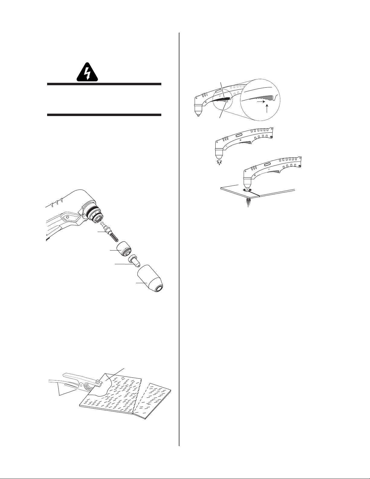
A. Torch Parts Selection
Check the torch for proper assembly and appropriate torch parts. The torch parts must correspond
with the type of operation, and with the amperage
output of this Power Supply (35 amps maximum).
Use only genuine manufactured parts with this
torch.
• Refer to Section 1 for necessary safety precautions.
Trigger
1
2
Trigger Release
3
4
Art # A-03383
Electrode
9-8215
Start Cartridge
9-8213
Tip
9-8207
Art # A-04388
Shield Cup
9-8218
B. Torch Connection
Check that the torch is properly connected.
C. Connect Work Cable
Make a clean work cable
connection to the workpiece or cutting table
Work Cable
And Clamp
Art # A-04389
Operation 4-2 Manual 0-4681
Page 15

E. Typical Cutting Speeds
Cutting speeds vary according to torch output, the type of material being cut, and operator skill. Speeds
shown are typical for this cutting system using air plasma to cut mild steel, with output current at the
highest setting and the torch used in the Drag mode or standoff height indicated.
Unit Standoff
FP-35A Drag (10GA) 0.135" ( 3mm) 94.7 2367 75.7 1893
FP-35A Drag (7GA) 0.179" (4.5mm) 57.0 1425 45.6 1140
FP-35A 1/8" (3mm) 1/4" (6mm) 36.3 908 29.1 727
FP-35A 1/8" (3mm) 3/8" (10mm) 15.3 383 12.3 307
FP-35A 1/8" (3mm) 1/2" (12mm) 9.7 242 7.7 193
Material
Thickness
Maximum Travel Speed
(ipm , mm/m)
Recommended Travel Speed
(imp , mm/m)
NOTE:
Drag or Drag mode refers to the torch tip being in contact with the work piece at all times.
Manual 0-4681 4-3 Operation
Page 16

Operation 4-4 Manual 0-4681
Page 17

SECTION 5:
SERVICE
5.01 General Maintenance
1. Basic Troubleshooting Overview
This guide covers basic troubleshooting. It is helpful for
solving many of the common problems that can arise with
this system. If major complex subassemblies are faulty,
the unit must be returned to an authorized service center
for repair.
O-rings on the Torch require lubrication on a regular
basis, depending on how frequently the torch shield
cup is disconnected and re-connected. This will allow
the O-rings to remain pliable and provide a proper
seal. The O-rings will dry out, becoming hard and
cracked, if the O-ring lubricant is not used on a regular
basis. This can lead to potential performance problems.
Remove and apply a very light film of O-ring lubricant
(Catalog # 8-4025) to the O-rings on a weekly basis.
NOTE
DO NOT use other lubricants or grease on the torch
O-rings. They may not be designed to operate within
high temperatures or may contain “unknown elements” that may react with the atmosphere. This
reaction can leave contaminants inside the torch.
Either of these conditions can lead to inconsistent
performance or poor parts life.
Art # A-04394
Follow all instructions as listed and complete each section in the order presented.
2. Common Symptoms
A. Primary power switch is ON, but power indicator
doesn’t light.
1. Improper electrical connection.
a. Check the input cable line & connection.
b. Check input power that its turned on.
c. Check the input power fuse.
2. System was overloaded.
a. Turn Primary Power Switch Off and then On
again.
3. Switch may be faulty.
a. Return to an authorized service center for re-
pair.
B. Primary power switch is on, but the cooling fan
does not work.
1. No power / incorrect power to fan or failed fan.
Upper Groove
with Vent Holes
Must Remain Open
Upper O-Ring
in Correct Groove
Cat. #8-3487
Threads
Lower O-Ring
Cat. #8-3486
5.02 Basic Troubleshooting Guide
WARNING
There are extremely dangerous voltage and power
levels present inside this unit. Do not attempt to
diagnose or repair unless you have had training in
power electronics measurement and troubleshooting techniques.
a. Return to an authorized service center for re-
pair.
C. No air flow at torch when air check switch is turned
on.
1. Input air connection is disconnected.
a. Connect the input air.
2. Input air supply not working.
a. Check the compressor manufacturer's manual
for trouble shooting and follow local maintenance procedures.
3. Internal connection is disconnected or loose.
a. Check all air line connections and fittings.
4. Filter or control PCB faulty.
a. Return to an authorized service center for re-
pair.
Manual 0-4681 5-1 SERVICE
Page 18

D. Torch will not pilot when torch switch is activated.
E. Cut performance is diminished.
1. Gas pressure too high or too low.
a. Adjust gas pressure per pressure setting label
on power supply.
NOTE
It is possible to have enough air pressure to operate
the power supply but not enough air flow to operate
the torch.
2. Torch tip, start cartridge, or electrode missing.
a. Turn off power supply. Remove shield cup. In-
stall missing parts.
3. Start cartridge is stuck.
a. Turn off power supply. Remove shield cup, tip,
and start cartridge. Check lower end fitting on
start cartridge for free movement. Replace cartridge if lower end fitting does not move freely.
Start Cartridge
Lower End Fitting
1. Worn torch parts.
a. Check current setting. Check the Electrode and
Tip for excess wear.
New Electrode
Art # A-03284
Good Tip
Worn Electrode
Worn Tip
A-03406
b. Check that the lower end fitting on the start car-
tridge moves freely. Replace any or all parts as
needed.
Art # A-03621
4. Worn or faulty torch parts
a. Inspect torch consumable parts. Replace if nec-
essary.
5. Thermal Switch activated
a. Allow the cooling fan to run for 2 minutes or
longer until it will resume operation.
NOTE
When operating the torch in a normal condition, a
small amount of gas / air vents through the gap between the shield cup and torch handle. Do not attempt to over tighten the shield cup as irreparable
damage to internal components may result.
Art # A-04503
Start Cartridge
Lower End Fitting
Art # A-03621
Air will flow from gap
next to shield cup.
SERVICE 5-2 Manual 0-4681
Page 19

2. Poor Work Lead connection.
a. Check the connection of the Work Lead to the
work piece.
Make a clean work cable
connection to the workpiece or cutting table
Work Cable
And Clamp
Art # A-04389
3. Current sensor or PWM PCB faulty.
a. Return to an authorized service center for re-
pair.
F. Air flows continuously and torch switch latch
button doesn't work properly.
1. Torch Switch Latch button on front panel faulty.
a. Return to an authorized service center for re-
pair.
2. Control PCB faulty.
a. Return to an authorized service center for re-
pair.
5.03 Contact information
Thermal Dynamics Technical Service Dept.
Tel: 1-800-752-7622 (1-800-PLASMA2)
Fax: 1-800-221-4401
e-mail address: tdc-tech@thermadyne.com
Manual 0-4681 5-3 SERVICE
Page 20

SERVICE 5-4 Manual 0-4681
Page 21

Appendix 1: Operating Sequence, Block Diagram
Primary Input Power "On" or Plugged in
Power Supply On/Off Switch "On"
Green Power Indicator "On" and Fan is Running
More air flow is required
Red Air Indicator
Release Torch Switch
Air Set Switch "On"
Air Flows at Torch. Set Air Pressure Then Turn Air Set Switch "Off"
Check Torch parts
Air Flow at Torch Stops
alignment. PIP switches
need to be repaired by a
Qualified Technician
for Torch to Pilot than to
run the power supply.
Re-check regulator setting.
Pilot Arc goes out
Pilot Arc Ignition
Torch Tip to Work after Pilot Arc start
Start Cutting Operation
YES
Post Flow of Air, Approximately 10 Seconds Then Stops
Note: The Torch will be very hot! Do not set on or near flammable materials!
Power Supply On/Off Switch "Off"
Cutting Done ?
Torch Switch "Off"
Torch Switch "On"
No Pilot Arc
NO
Green Power Indicator "Off" and Fan Stops
Art # A-04390
Primary Input Power Switch "Off" or Unplugged
Manual 0-4681 A-1 APPENDIX
Page 22
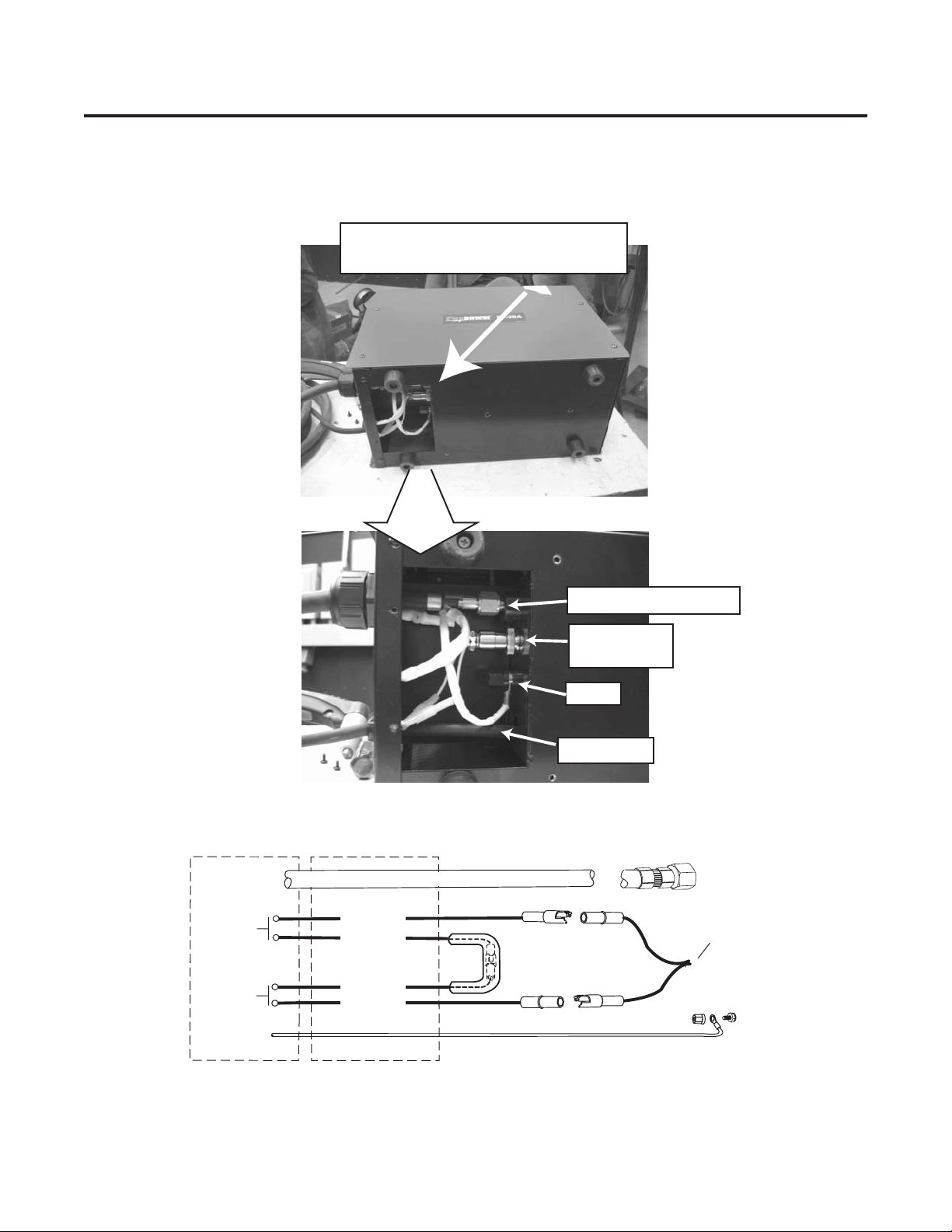
Appendix 2: Torch Connection
Art # A-04445
Disconnect power and air. Lay unit
on its side. Remove access plate.
DETAIL
Negative / Plasma Lead
Power Supply
Adapter
PIP
Switch
Torch
Switch
Torch Head
Negative / Plasma Lead
Black
Orange
Green
White
Pilot
Torch Leads
Pilot
Work Cable
To Power
Supply Adapter
Pilot
APPENDIX A-2 Manual 0-4681
Page 23

Appendix 3: Microchip Pin-Out
40 Pin Microchip
123456789101112
24222018161412108642
2321191715131197531
CPU
Socket on
Control
PCB
P2
P1
P3 123456789101112
Manual 0-4681 A-3 APPENDIX
Page 24

Appendix 4: Replacement Hand Torch Parts List
Item #QtyDescription Catalog #
1 1 Torch Handle Replacement Kit (include items no. 2 & 3) 9-7030
2 1 Trigger Assembly Replacement Kit 9-7034
3 1 Handle Screw Kit (5 each, #6-32 x 1/2" cap screw, and wrench) 9-8062
4 1 Torch Head Assembly Replacement Kit (includes items No. 5 & 6) 9-8219
5 1 Large O-Ring 8-3487
6 1 Small O-Ring 8-3486
7 Leads Assemblies with O2B Connectors (includes switch assemblies)
1 SL60 / 40Amp, 20 - foot Leads Assembly with O2B connectors 7-5241
8 1 Switch Kit 9-7031
APPENDIX A-4 Manual 0-4681
Page 25

7
1
2
4
5
6
3
8
7
A-07060
Manual 0-4681 A-5 APPENDIX
Page 26

INPUT
AC230V
1 PH
Appendix 5: System Schematic
230 VAC
DIODE
W
N/C
W
DC
325
L
N
G
Black
White
To Ground
Connection
NFB
230 VAC
TB1
Filter Board
No.40276003
CN2
W
BR
TB2
CN1
W
B
230 VAC
Red
BL
C1 C2
IGBT IGBT
R1
G1
E2 G4
E1 G2
G3 E4E3
B
PS
Closes At
30 PSI
85Ω
B
AC230
Solenoid V/V
T1
Pressure
Sensor
AC12
AC18
BK
AC18 VAC
R
FAN
BL
BL
R
Pale OR
OR
N.C
SW
TW TW TW TW
B W G R B W G R
E4 G3 G2
G4 E3
1
23 4123 4
+12VDC
W
TH
2
CN5
1
W
CN6
LD1
SOL
E1E2 G1
CN8
N/C
BL
N/C
R
CN1
+25VDC
2
CN4
1
+12VDC
2
CN7
1
Control Board
No.40271003
LD3
CO
CN2
16
1
Red
CN1
NOTE:
Do Not attempt to adjust the POTs!
Art # A-04890
APPENDIX A-6 Manual 0-4681
MAIN
POWER
TEMP
ERROR
Page 27

218
VAC
C/T 1
Main Transformer
194VAC
C3
R2
C4
R3
C5
R4
Piloting Current
Current Sensor
VC_1
VD_1
OU_1
GN_1
Cutting Current
WORK
OU_2
O.C.V. 325
Pilot 130
Cutting 110
C6
R5
REACTOR
WW
TORCH
LD2
Enable
+12VDC
to engage
Pilot Relay
Panel Board
No.40270601
AIR
ERROR
HOLD
CN9
W
Twisted
+12VDC
-12VDC
+12VDC
HOLD
AIR
SET
CN10
CN12
CN3
CN11
N/C
Pilot
Relay
PILOT
VC_1
VD_1
OU_1
VC_2
GN_1
BR
Red
V
Y
G
Torch
Filter
1
2
3
4
5
Y
1
2
Y
W
2
1
W
S/W
S/W
PCR
P.B.
Jumper
NOTE:
Do Not attempt to
adjust the POTs!
To Current
Sensor
Y
77
Ω
10.3 MF
Pilot
Y
630V
POWWEL ELECTRONIC IND.CO., LTD.
Air Plasma 35A
2005 / 01 / 12
Art # A-04890
Manual 0-4681 A-7 APPENDIX
 Loading...