

Page 1

FABRICATOR
®
211i
3-IN-1 Multi Process
Welding Systems
Service
Manual
Revision: AD Issue Date: June 19, 2015 Manual No.: 0-5226
Tweco.com
Page 2

WE APPRECIATE YOUR BUSINESS!
Congratulations on receiving your new Tweco product. We are proud to have you as our customer and
will strive to provide you with the best service and support in the industry. This product is backed by
our extensive warranty and world-wide service network.
We know you take pride in your work and we feel privileged to provide you with this high performance
product that will help you get the job done.
For more than 75 years Tweco has provided quality products you can trust, when your reputation is on
the line.
YOU ARE IN GOOD COMPANY!
Tweco is a Global Brand of Arc Welding Products for Victor Technologies Inc. We distinguish
ourselves from our competition through market-leading innovation and truly dependable products that
will stand the test of time.
We strive to enhance your productivity, efficiency and welding performance enabling you to excel in
your craft. We design products with the welder in mind delivering- advanced features, durability, ease
of use and ergonomic comfort.
Above all, we are committed to a safer working environment within the welding industry. Your
satisfaction with this product and its safe operation is our ultimate concern. Please take the time to
read the entire manual, especially the Safety Precautions.
If you have any questions or concerns regarding your new Tweco product, please contact our friendly
and knowledgeable Customer Service Team at:
1-800-462-2782 (USA) and 1-905-827-4515 (Canada),
or visit us on the web at www.Tweco.com
Page 3

!
WARNINGS
Read and understand this entire Manual and your employer’s safety practices before installing,
operating, or servicing the equipment.
While the information contained in this Manual represents the Manufacturer’s best judgment,
the Manufacturer assumes no liability for its use.
Service Manual Number 0-5226 for:
Tweco Fabricator 211i Inverter Power Supply Part Number W1004206
Tweco Fabricator 211i Inverter System Part Number W1004207
Published by:
Victor Technologies International, Inc.
Europa Building
Chorley Industrial Park
Chorley, Lancaster,
England, PR6 7BX
www.victortechnologies.com
Copyright 2012, 2013 by
Victor Technologies International, Inc.
All rights reserved.
Reproduction of this work, in whole or in part, without written permission of the
publisher is prohibited.
The publisher does not assume and hereby disclaims any liability to any party for any
loss or damage caused by any error or omission in this Manual, whether such error
results from negligence, accident, or any other cause.
Publication Date: March 07, 2012
Revision Date: June 19, 2015
Record the following information for Warranty purposes:
Where Purchased: ____________________________________
Purchase Date: ____________________________________
Equipment Serial #: ____________________________________
Page 4

TABLE OF CONTENTS
SECTION 1:
SAFETY INSTRUCTIONS AND WARNINGS ....................................................... 1-1
1.01 Arc Welding Hazards ....................................................................................... 1-1
1.02 Principal Safety Standards .............................................................................. 1-5
1.03 Symbol Chart .................................................................................................. 1-6
1.04 Servicing Hazards ........................................................................................... 1-7
1.05 EMF Information ............................................................................................. 1-9
SECTION 2:
INTRODUCTION ..................................................................................... 2-1
2.01 How To Use This Manual ................................................................................ 2-1
2.02 Equipment Identification ................................................................................. 2-1
2.03 Receipt Of Equipment ..................................................................................... 2-1
2.04 Description ..................................................................................................... 2-1
2.05 User Responsibility ......................................................................................... 2-2
2.06 Transportation Methods .................................................................................. 2-2
2.07 Packaged Items .............................................................................................. 2-2
SECTION 3:
SAFETY AND INSTALLATION ....................................................................... 3-1
3.01 Duty Cycle ....................................................................................................... 3-1
3.02 Specifications ................................................................................................. 3-2
3.03 Environment ................................................................................................... 3-2
3.04 Location .......................................................................................................... 3-3
3.05 Ventilation ....................................................................................................... 3-3
3.06 Mains Supply Voltage Requirements .............................................................. 3-3
3.07 Electrical Input Connections ........................................................................... 3-4
3.08 Electromagnetic Compatibility ........................................................................ 3-4
3.09 Volt-Ampere Curves ........................................................................................ 3-6
SECTION 4:
operation .............................................................................................. 4-1
4.01 Power Source Controls, Indicators and Features ............................................ 4-1
4.02 Attaching MIG Gun ........................................................................................ 4-7
4.03 Installing 15kg Spool (300mm diameter) ...................................................... 4-8
4.04 Installing 5kg Spool (200mm diameter) ......................................................... 4-8
4.05 Inserting Wire into the Wire Feed Mechanism ................................................ 4-9
4.06 Feed Roller Pressure Adjustment .................................................................. 4-10
4.07 Changing the Feed Roll ................................................................................. 4-10
4.08 Wire Reel Brake ............................................................................................ 4-11
4.09 Setup for MIG (GMAW) Welding with Gas Shielded MIG Wire ..................... 4-11
4.10 Setup for MIG (FCAW) Welding with Gasless MIG Wire ............................... 4-13
4.11 Setup for SPOOL GUN MIG (GMAW) Welding with Gas Shielded MIG Wire . 4-14
4.12 Setup for TIG (GTAW) Welding ..................................................................... 4-15
4.13 Setup for STICK (MMA) Welding ................................................................. 4-17
4.14 Leak Testing the System ............................................................................... 4-18
Page 5

TABLE OF CONTENTS
SECTION 5:
TROUBLESHOOTING ................................................................................ 5-1
5.01 Basic Troubleshooting-Power Source Faults ................................................... 5-1
5.02 Routine Service and Calibration Requirements ............................................... 5-2
5.03 Check Unit before Applying Power .................................................................. 5-4
5.04 Test Equipment and Tools Needed for Troubleshooting and Servicing ............ 5-5
5.05 Visually Inspect ............................................................................................... 5-5
5.06 Preliminary DC Bus Measurement of the Main Inverter Board ........................ 5-6
5.07 Preliminary Check of the Main Inverter Board ................................................ 5-7
5.08 Check Main Input Rectifier .............................................................................. 5-8
5.09 DC Bus Voltage Measurement ........................................................................ 5-9
5.10 PCB Connectors ............................................................................................ 5-10
5.11 DIP Switch Settings, Control PCB ................................................................. 5-16
5.12 Calibration .................................................................................................... 5-17
5.13 Circuit Diagram ............................................................................................. 5-19
5.14 Main Circuit Description ............................................................................... 5-20
SECTION 6:
DISASSEMBLY PROCEDURE ....................................................................... 6-1
6.01 Safety Precautions for Disassembly ............................................................... 6-1
6.02 Control Board Removal ................................................................................... 6-2
6.03 Front Panel Assembly Removal ...................................................................... 6-3
6.04 Front Panel (Operator Interface) Circuit Board PCB3 Removal ....................... 6-4
6.05 Back Panel Removal ....................................................................................... 6-5
6.06 Power Switch S1 and Power Cord Removal ................................................... 6-6
6.07 Base Panel Removal ....................................................................................... 6-7
SECTION 7:
ASSEMBLY PROCEDURES .......................................................................... 7-1
7.01 Installing Base Board ...................................................................................... 7-1
7.02 Installing Back Panel ....................................................................................... 7-2
7.03 Installing Front Panel ...................................................................................... 7-3
7.04 Installing Main Control Panel and Clear Cover Sheet ...................................... 7-4
7.05 Installing Case ................................................................................................ 7-6
SECTION 8:
KEY SPARE PARTS ................................................................................... 8-1
8.01 Power Source Spare Parts .............................................................................. 8-1
SECTION 9:
OptionAL Accessories ............................................................................... 9-1
9.01 Optional Accessories ...................................................................................... 9-1
TWECO - LIMITED WARRANTY TERMS
TERMS OF WARRANTY - JANUARY 2011
Page 6

This Page Intentionally Blank
Page 7
SAFETY INSTRUCTIONS FABRICATOR 211i
Manual 0-5226 1-1 SAFETY INSTRUCTIONS AND WARNINGS
1.01 Arc Welding Hazards
WARNING
ELECTRIC SHOCK can kill.
Touching live electrical parts can cause
fatal shocks or severe burns. The electrode
and work circuit is electrically live whenever the output is on. The input power circuit and machine internal circuits are also
live when power is on. In semi-automatic
or automatic wire welding, the wire, wire
reel, drive roll housing, and all metal parts
touching the welding wire are electrically
live. Incorrectly installed or improperly
grounded equipment is a hazard.
1. Do not touch live electrical parts.
2. Wear dry, hole-free insulating gloves and body
protection.
3. Insulate yourself from work and ground using dry
insulating mats or covers.
4. Disconnect input power or stop engine before
installing or servicing this equipment. Lock input
power disconnect switch open, or remove line
fuses so power cannot be turned on accidentally.
5. Properly install and ground this equipment
according to its Owner’s Manual and national,
state, and local codes.
6. Turn OFF all equipment when not in use.
Disconnect power to equipment if it will be left
unattended or out of service.
7. Use fully insulated electrode holders. Never dip
holder in water to cool it or lay it down on the
ground or the work surface. Do not touch holders
connected to two welding machines at the same
time or touch other people with the holder or
electrode.
8. Do not use worn, damaged, undersized, or poorly
spliced cables.
9. Do not wrap cables around your body.
10. Ground the workpiece to a good electrical (earth)
ground.
11. Do not touch electrode while in contact with the
work (ground) circuit.
12. Use only well-maintained equipment. Repair or
replace damaged parts at once.
13. In confined spaces or damp locations, do not use
a welder with AC output unless it is equipped with
a voltage reducer. Use equipment with DC output.
14. Wear a safety harness to prevent falling if working
above floor level.
15. Keep all panels and covers securely in place.
SECTION 1:
SAFETY INSTRUCTIONS AND WARNINGS
!
WARNING
PROTECT YOURSELF AND OTHERS FROM POSSIBLE SERIOUS INJURY OR DEATH. KEEP CHILDREN AWAY. PACEMAKER WEARERS KEEP AWAY UNTIL CONSULTING YOUR DOCTOR. DO NOT
LOSE THESE INSTRUCTIONS. READ OPERATING/INSTRUCTION MANUAL BEFORE INSTALLING,
OPERATING OR SERVICING THIS EQUIPMENT.
Welding products and welding processes can cause serious injury or death, or damage to other equipment or
property, if the operator does not strictly observe all safety rules and take precautionary actions.
Safe practices have developed from past experience in the use of welding and cutting. These practices must be
learned through study and training before using this equipment. Some of these practices apply to equipment
connected to power lines; other practices apply to engine driven equipment. Anyone not having extensive
training in welding and cutting practices should not attempt to weld.
Safe practices are outlined in the European Standard EN60974-1 entitled: Safety in welding and allied processes
Part 2: Electrical. This publication and other guides to what you should learn before operating this equipment
are listed at the end of these safety precautions. HAVE ALL INSTALLATION, OPERATION, MAINTENANCE,
AND REPAIR WORK PERFORMED ONLY BY QUALIFIED PEOPLE.
Page 8

FABRICATOR 211i SAFETY INSTRUCTIONS
SAFETY INSTRUCTIONS AND WARNINGS 1-2 Manual 0-5226
WARNING
ARC RAYS can burn eyes and skin; NOISE
can damage hearing. Arc rays from the
welding process produce intense heat and
strong ultraviolet rays that can burn eyes
and skin. Noise from some processes can
damage hearing.
1. Wear a welding helmet fitted with a proper shade
of filter (see ANSI Z49.1 listed in Safety Standards)
to protect your face and eyes when welding or
watching.
2. Wear approved safety glasses. Side shields
recommended.
3. Use protective screens or barriers to protect others
from flash and glare; warn others not to watch the
arc.
4. Wear protective clothing made from durable,
flame-resistant material (wool and leather) and
foot protection.
5. Use approved ear plugs or ear muffs if noise level
is high.
6. Never wear contact lenses while welding.
AWS F2.2:2001 (R2010), Adapted with permission of the American Welding Society (AWS), Miami, Florida
Guide for Shade Numbers
Process
Electrode Size in.
(mm)
Arc Current
(Amperes)
Minimum
Protective
Shade
Suggested*
Shade No.
(Comfort)
Shielded Metal Arc Welding
(SMAW)
Less than 3/32 (2.4)
3/32-5/32 (2.4-4.0)
5/32-1/4 (4.0-6.4)
More than 1/4 (6.4)
Less than 60
60-160
160-250
250-550
7
8
10
11
10
12
14
Gas Metal Arc Welding (GMAW)
and Flux Cored Arc Welding
(FCAW)
Less than 60
60-160
160-250
250-550
7
10
10
10
11
12
14
Gas Tungsten arc Welding
(GTAW)
Less than 50
50-150
150-500
8
8
10
10
12
14
Air Carbon Arc Cutting (CAC-A)
(Light)
(Heavy)
Less than
500
500-1000
10
11
12
14
Plasma Arc Welding (PAW)
Less than 20
20-100
100-400
400-800
6
8
10
11
6 to 8
10
12
14
Plasma Arc Cutting (PAC)
Less than 20
20-40
40-60
60-80
80-300
300-400
400-800
4
5
6
8
8
9
10
4
5
6
8
9
12
14
* As a rule of thumb, start with a shade that is too dark to see the weld zone. Then go to a lighter
shade which gives sufficient view of the weld zone without going below the minimum. In oxyfuel gas
welding, cutting, or brazing where the torch and/or the flux produces a high yellow light, it is desirable
to use a filter lens that absorbs the yellow or sodium line of the visible light spectrum.
Page 9
SAFETY INSTRUCTIONS FABRICATOR 211i
Manual 0-5226 1-3 SAFETY INSTRUCTIONS AND WARNINGS
WARNING
FUMES AND GASES can be hazardous to
your health.
Welding produces fumes and gases.
Breathing these fumes and gases can be
hazardous to your health.
1. Keep your head out of the fumes. Do not breathe
the fumes.
2. If inside, ventilate the area and/or use exhaust at
the arc to remove welding fumes and gases.
3. If ventilation is poor, use an approved air-supplied
respirator.
4. Read the Material Safety Data Sheets (MSDSs)
and the manufacturer’s instruction for metals,
consumables, coatings, and cleaners.
5. Work in a confined space only if it is well ventilated,
or while wearing an air-supplied respirator.
Shielding gases used for welding can displace air
causing injury or death. Be sure the breathing air
is safe.
6. Do not weld in locations near degreasing, cleaning,
or spraying operations. The heat and rays of the
arc can react with vapours to form highly toxic
and irritating gases.
7. Do not weld on coated metals, such as galvanized,
lead, or cadmium plated steel, unless the coating
is removed from the weld area, the area is well
ventilated, and if necessary, while wearing an airsupplied respirator. The coatings and any metals
containing these elements can give off toxic fumes
if welded.
WARNING
WELDING can cause fire or explosion.
Sparks and spatter fly off from the
welding arc. The flying sparks and hot
metal, weld spatter, hot workpiece, and
hot equipment can cause fires and burns.
Accidental contact of electrode or welding
wire to metal objects can cause sparks,
overheating, or fire.
1. Protect yourself and others from flying sparks and
hot metal.
2. Do not weld where flying sparks can strike
flammable material.
3. Remove all flammables within 35 ft (10.7 m) of the
welding arc. If this is not possible, tightly cover
them with approved covers.
4. Be alert that welding sparks and hot materials from
welding can easily go through small cracks and
openings to adjacent areas.
5. Watch for fire, and keep a fire extinguisher nearby.
6. Be aware that welding on a ceiling, floor, bulkhead,
or partition can cause fire on the hidden side.
7. Do not weld on closed containers such as tanks
or drums.
8. Connect work cable to the work as close to the
welding area as practical to prevent welding
current from travelling long, possibly unknown
paths and causing electric shock and fire hazards.
9. Do not use welder to thaw frozen pipes.
10. Remove stick electrode from holder or cut off
welding wire at contact tip when not in use.
WARNING
FLYING SPARKS AND HOT METAL can
cause injury.
Chipping and grinding cause flying metal.
As welds cool, they can throw off slag.
1. Wear approved face shield or safety goggles. Side
shields recommended.
2. Wear proper body protection to protect skin.
WARNING
CYLINDERS can explode if damaged.
Shielding gas cylinders contain gas under
high pressure. If damaged, a cylinder can
explode. Since gas cylinders are normally
part of the welding process, be sure to
treat them carefully.
1. Protect compressed gas cylinders from excessive
heat, mechanical shocks, and arcs.
2. Install and secure cylinders in an upright position
by chaining them to a stationary support or
equipment cylinder rack to prevent falling or
tipping.
3. Keep cylinders away from any welding or other
electrical circuits.
4. Never allow a welding electrode to touch any
cylinder.
Page 10

FABRICATOR 211i SAFETY INSTRUCTIONS
SAFETY INSTRUCTIONS AND WARNINGS 1-4 Manual 0-5226
5. Use only correct shielding gas cylinders,
regulators, hoses, and fittings designed for the
specific application; maintain them and associated
parts in good condition.
6. Turn face away from valve outlet when opening
cylinder valve.
7. Keep protective cap in place over valve except
when cylinder is in use or connected for use.
8. Read and follow instructions on compressed
gas cylinders, associated equipment, and CGA
publication P-1 listed in Safety Standards.
!
WARNING
Engines can be dangerous.
WARNING
ENGINE EXHAUST GASES can kill.
Engines produce harmful exhaust gases.
1. Use equipment outside in open, well-ventilated
areas.
2. If used in a closed area, vent engine exhaust
outside and away from any building air intakes.
WARNING
ENGINE FUEL can cause fire or explosion.
Engine fuel is highly flammable.
1. Stop engine before checking or adding fuel.
2. Do not add fuel while smoking or if unit is near
any sparks or open flames.
3. Allow engine to cool before fuelling. If possible,
check and add fuel to cold engine before beginning
job.
4. Do not overfill tank — allow room for fuel to
expand.
5. Do not spill fuel. If fuelling is spilled, clean up
before starting engine.
WARNING
MOVING PARTS can cause injury.
Moving parts, such as fans, rotors, and belts can cut
fingers and hands and catch loose clothing.
1. Keep all doors, panels, covers, and guards
closed and securely in place.
2. Stop engine before installing or connecting
unit.
3. Have only qualified people remove guards or
covers for maintenance and troubleshooting
as necessary.
4. To prevent accidental starting during servicing,
disconnect negative (-) battery cable from
battery.
5. Keep hands, hair, loose clothing, and tools
away from moving parts.
6. Reinstall panels or guards and close doors
when servicing is finished and before starting
engine.
WARNING
SPARKS can cause BATTERY GASES TO
EXPLODE; BATTERY ACID can burn eyes
and skin.
Batteries contain acid and generate explosive gases.
1. Always wear a face shield when working on a
battery.
2. Stop engine before disconnecting or connecting
battery cables.
3. Do not allow tools to cause sparks when working
on a battery.
4. Do not use welder to charge batteries or jump start
vehicles.
5. Observe correct polarity (+ and –) on batteries.
WARNING
STEAM AND PRESSURIZED HOT
COOLANT can burn face, eyes, and skin.
The coolant in the radiator can be very hot
and under pressure.
1. Do not remove radiator cap when engine is hot.
Allow engine to cool.
2. Wear gloves and put a rag over cap area when
removing cap.
3. Allow pressure to escape before completely
removing cap.
Page 11
SAFETY INSTRUCTIONS FABRICATOR 211i
Manual 0-5226 1-5 SAFETY INSTRUCTIONS AND WARNINGS
!
WARNING
WARNING: This product contains chemi-
cals, including lead, known to the State
of California to cause birth defects and
other reproductive harm.
Wash hands
after handling.
NOTE
Considerations About Welding And The
Effects of Low Frequency Electric and
Magnetic Fields
The following is a quotation from the General Conclusions Section of the U.S. Congress, Office of
Technology Assessment, Biological Effects of Power
Frequency Electric & Magnetic Fields - Background
Paper, OTA-BP-E-63 (Washington, DC: U.S. Government Printing Office, May 1989): “...there is now
a very large volume of scientific findings based on
experiments at the cellular level and from studies with
animals and people which clearly establish that low
frequency magnetic fields interact with, and produce
changes in, biological systems. While most of this
work is of very high quality, the results are complex.
Current scientific understanding does not yet allow us
to interpret the evidence in a single coherent framework. Even more frustrating, it does not yet allow
us to draw definite conclusions about questions of
possible risk or to offer clear science-based advice
on strategies to minimize or avoid potential risks.”
To reduce magnetic fields in the workplace, use the
following procedures.
1. Keep cables close together by twisting or
taping them.
2. Arrange cables to one side and away from the
operator.
3. Do not coil or drape cable around the body.
4. Keep welding Power Source and cables as far
away from body as practical.
ABOUT PACEMAKERS:
The above procedures are among
those also normally recommended for
pacemaker wearers. Consult your doctor
for complete information.
1.02 Principal Safety Standards
Safety in Welding and Cutting, ANSI Standard Z49.1,
from American Welding Society, 550 N.W. LeJeune
Rd., Miami, FL 33126.
Safety and Health Standards, OSHA 29 CFR 1910,
from Superintendent of Documents, U.S. Government
Printing Office, Washington, D.C. 20402.
Recommended Safe Practices for the Preparation for
Welding and Cutting of Containers That Have Held
Hazardous Substances, American Welding Society
Standard AWS F4.1, from American Welding Society,
550 N.W. LeJeune Rd., Miami, FL 33126.
National Electrical Code, NFPA Standard 70, from
National Fire Protection Association, Batterymarch
Park, Quincy, MA 02269.
Safe Handling of Compressed Gases in Cylinders, CGA
Pamphlet P-1, from Compressed Gas Association,
1235 Jefferson Davis Highway, Suite 501, Arlington,
VA 22202.
Code for Safety in Welding and Cutting, CSA Standard
W117.2, from Canadian Standards Association,
Standards Sales, 178 Rexdale Boulevard, Rexdale,
Ontario, Canada M9W 1R3.
Safe Practices for Occupation and Educational Eye and
Face Protection, ANSI Standard Z87.1, from American
National Standards Institute, 1430 Broadway, New
York, NY 10018.
Cutting and Welding Processes, NFPA Standard
51B, from National Fire Protection Association,
Batterymarch Park, Quincy, MA 02269.
Page 12
FABRICATOR 211i SAFETY INSTRUCTIONS
SAFETY INSTRUCTIONS AND WARNINGS 1-6 Manual 0-5226
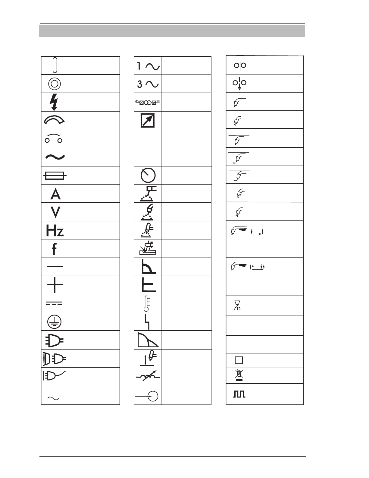
1.03 Symbol Chart
Note that only some of these symbols will appear on your model.
Gas Tungsten Arc
Welding (GTAW)
Air Carbon Arc
Cutting (CAC-A)
Constant Current
Constant Voltage
Or Constant Potential
High Temperature
Fault Indication
Arc Force
Touch Start (GTAW)
Variable Inductance
Voltage Input
Single Phase
Three Phase
Three Phase Static
Frequency ConverterTransformer-Rectifier
Dangerous Voltage
OFF
ON
Panel/Local
Shielded Metal
Arc Welding (SMAW)
Gas Metal Arc
Welding (GMAW)
Increase/Decrease
Circuit Breaker
AC Auxiliary Power
Remote
Duty Cycle
Percentage
Amperage
Voltage
Hertz (cycles/sec)
Frequency
Negative
Positive
Direct Current (DC)
Protective Earth
(Ground)
Line
Line Connection
Auxiliary Power
Receptacle RatingAuxiliary Power
Art # A-10663_AB
115V 15A
t
t1
t2
%
X
IPM
MPM
t
V
Fuse
Wire Feed Function
Wire Feed Towards
Workpiece With
Output Voltage OFF.
Preflow Time
Postflow Time
Spot Time
Spot Weld Mode
Continuous Weld
Mode
Press to initiate wirefeed and
welding, release to stop.
Purging Of Gas
Inches Per Minute
Meters Per Minute
Welding Gun
Burnback Time
Press and hold for preflow, release
to start arc. Press to stop arc, and
hold for preflow.
4 Step Trigger
Operation
2 Step Trigger
Operation
S
See Note
See Note
Pulse Welding
Page 13
SAFETY INSTRUCTIONS FABRICATOR 211i
Manual 0-5226 1-7 SAFETY INSTRUCTIONS AND WARNINGS
1.04 Servicing Hazards
!
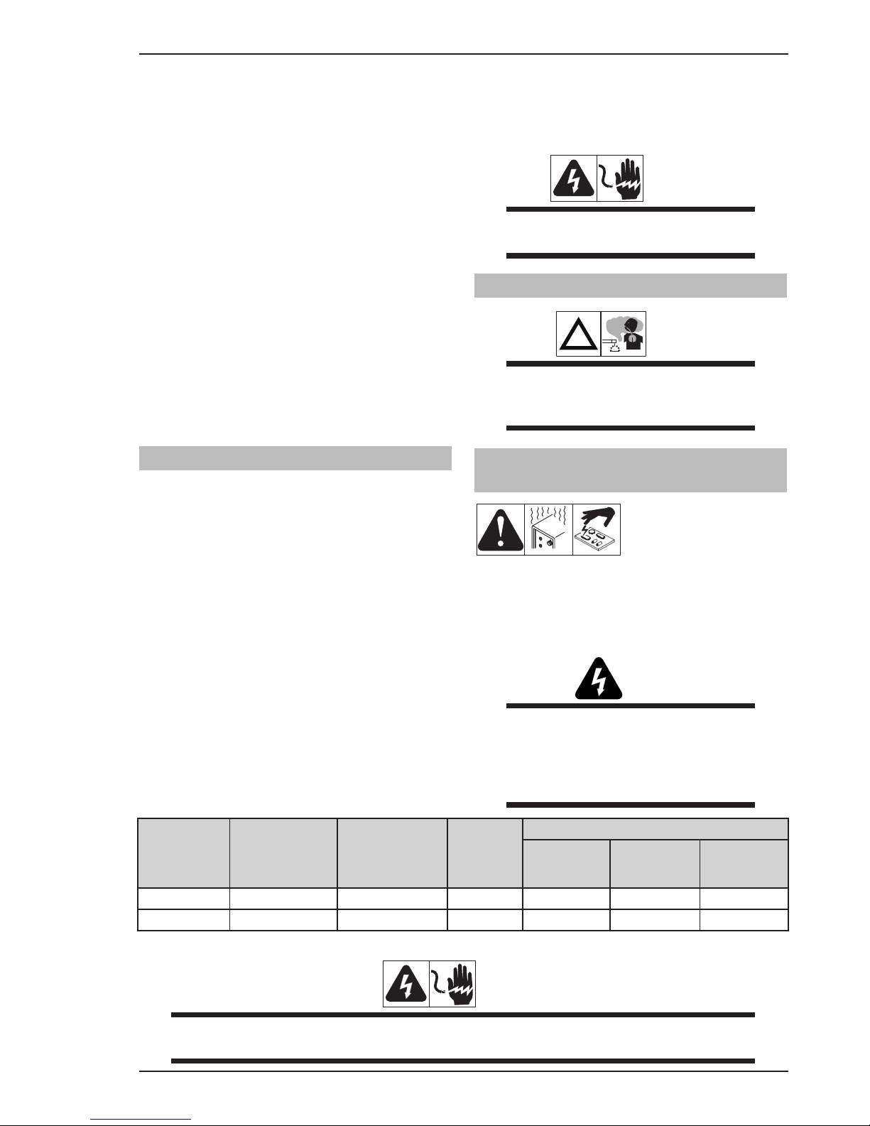
WARNING
The symbols shown below are used
throughout this manual to call attention to
and identify possible hazards. When you
see the symbol, watch out, and follow the
related instructions to avoid the hazard.
Only qualified persons should test, maintain, and repair this unit.
Only qualified persons should test, maintain, and repair this unit.
WARNING
ELECTRIC SHOCK can kill.
• Donottouchliveelectricalparts.
• TurnOffweldingpowersourceandwirefeeder
and disconnect and lockout input power using
line disconnect switch, circuit breakers, or by
removing plug from receptacle, or stop engine
before servicing unless the procedure specifically requires an energized unit.
• Insulateyourselffromgroundbystandingor
working on dry insulating mats big enough to
prevent contact with the ground.
• Donotleaveliveunitunattended.
• Ifthisprocedurerequiresandenergizedunit,
have only personnel familiar with and following
standard safety practices do the job.
• When testing a live unit, use the one-hand
method. Do not put both hands inside unit. Keep
one hand free.
• Disconnect input power conductors from de-
energized supply line BEFORE moving a welding
power source.
SIGNIFICANT DC VOLTAGE exists after removal
of input power on inverters.
• TurnOffinverters,disconnectinputpower,and
discharge input capacitors according to instructions in Troubleshooting Section before touching
any parts.
WARNING
STATIC (ESD) can damage PC boards.
• PutongroundedwriststrapBEFOREhandling
boards or parts.
• Useproperstatic-proofbagsandboxestostore,
move, or ship PC boards.
WARNING
FIRE OR EXPLOSION hazard.
• Donotplaceuniton,over,ornearcombustible
surfaces.
• Donotserviceunitnearammables.
WARNING
FLYING METAL or DIRT can injure eyes.
• Wearsafetyglasseswithsideshieldsorface
shield during servicing.
• Becareful not to short metal tools, parts, or
wires together during testing and servicing.
WARNING
HOT PARTS can cause sever burns.
• Donottouchhotpartsbarehanded.
• Allowcoolingperiodbeforeworkingonequip-
ment.
• To handle not parts, use proper tools and/or
wear heavy, insulated welding gloves and clothing to prevent burns.
WARNING
EXPLODING PARTS can cause injury.
• Failedpartscanexplodeorcauseotherpartsto
explode when power is applied to inverters.
• Alwayswearafaceshieldandlongsleeveswhen
servicing inverters.
WARNING
SHOCK HAZARD from testing.
• TurnOffweldingpowersourceandwirefeeder
or stop engine before making or changing meter
lead connections.
• Use at least one meter lead that has a self-
retaining spring clip such as an alligator clip.
• Readinstructionsfortestequipment.
Page 14
FABRICATOR 211i SAFETY INSTRUCTIONS
SAFETY INSTRUCTIONS AND WARNINGS 1-8 Manual 0-5226
WARNING
FALLING UNIT can cause injury.
• Useliftingeyetoliftunitonly,NOTrunninggear,
gas cylinders, or any other accessories.
• Useequipmentofadequatecapacitytoliftand
support unit.
• Ifusingliftforkstomoveunit,besureforksare
long enough to extend beyond opposite side of
unit.
WARNING
MOVING PARTS can cause injury,
• Keepawayfrommovingpartssuchasfans.
• Keepawayfrompinchpointssuchasdriverolls.
• Have only qualified persons remove doors,
panels, covers, or guards for maintenance as
necessary.
• Keephands,hair,looseclothing,andtoolsaway
from moving parts.
• Reinstalldoors,panels,covers,orguardswhen
maintenance is finished and before reconnecting
input power.
WARNING
MAGNETIC FIELDS can affect Implanted
Medical Devices.
• WearersofPacemakers and other Implanted
Medical Devices should keep away from servicing areas until consulting their doctor and the
device manufacturer.
WARNING
OVERUSE can cause OVERHEATING.
• Allowcoolingperiod;followrateddutycycle.
• Reduce current or reduce duty cyclebefore
starting to weld again.
• Donotblockorlterairowtounit.
WARNING
H.F. RADIATION can cause interference.
• High-frequency(H.F.)caninterferewithradio
navigation, safety services, computers, and
communications equipment.
• Haveonlyqualiedpersonsfamiliarwithelectronic equipment install, test, and service H.F.
producing units.
• Theuserisresponsiblefor having a qualied
electrician promptly correct any interference
problem resulting from the installation.
• IfnotiedbytheFCCaboutinterference,stop
using the equipment at once.
• Have the installation regularly checked and
maintained.
• Keephigh-frequencysourcedoorsandpanels
tightly shut, keep spark gaps at correct setting,
and use grounding and shielding to minimize
the possibility of interference.
!
WARNING
READ INSTRUCTIONS.
• UseTestingBooklet(PartNo.150853) when
servicing this unit.
• ConsulttheOwner’sManualforweldingsafety
precautions.
• Useonlygenuinereplacementpartsfrom the
manufacturer.
Page 15

SAFETY INSTRUCTIONS FABRICATOR 211i
Manual 0-5226 1-9 SAFETY INSTRUCTIONS AND WARNINGS
1.05 EMF Information
Considerations About Welding And The Effects Of Low Frequency Electric And Magnetic Fields
Welding current, as it flows through welding cables, will cause electromagnetic fields. There has been and
still is some concern about such fields. However, after examining more than 500 studies spanning 17 years
of research, a special blue ribbon committee of the National Research Council concluded that: “The body of
evidence, in the committee’s judgment, has not demonstrated that exposure to power-frequency electric and
magnetic fields is a human-health hazard.” However, studies are still going forth and evidence continues to be
examined. Until the final conclusions of the research are reached, you may wish to minimize your exposure
to electromagnetic fields when welding or cutting.
To reduce magnetic fields in the workplace, use the following procedures:
1. Keep cables close together by twisting or taping them, or using a cable cover.
2. Arrange cables to one side and away from the operator.
3. Do not coil or drape cables around your body.
4. Keep welding power source and cables as far away from operator as practical.
5. Connect work clamp to workpiece as close to the weld as possible.
About Implanted Medical Devices:
Implanted Medical Device wearers should consult their doctor and the device manufacturer before performing or going near arc welding, spot welding, gouging, plasma arc cutting, or induction heating operations. If
cleared by your doctor, then following the above procedures is recommended.
Page 16

FABRICATOR 211i SAFETY INSTRUCTIONS
SAFETY INSTRUCTIONS AND WARNINGS 1-10 Manual 0-5226
This Page Intentionally Blank
Page 17
INTRODUCTION FABRICATOR 211i
Manual 0-5226 2-1 INTRODUCTION
SECTION 2:
INTRODUCTION
2.03 Receipt Of Equipment
When you receive the equipment, check it against the
invoice to make sure it is complete and inspect the
equipment for possible damage due to shipping. If there
is any damage, notify the carrier immediately to file a
claim. Furnish complete information concerning damage
claims or shipping errors to the location in your area
listed in the inside back cover of this manual.
Include all equipment identification numbers as described above along with a full description of the parts
in error.
Move the equipment to the installation site before
un-crating the unit. Use care to avoid damaging the
equipment when using bars, hammers, etc., to un-crate
the unit.
2.04 Description
The Tweco Fabricator 211i is a self contained single
phase multi process welding inverter that is capable of
performing MIG (GMAW/FCAW), STICK (MMA) and LIFT
TIG (GTAW) welding processes. The unit is equipped
with an integrated wire feed unit, digital voltage and
amperage meters, and a host of other features in order
to fully satisfy the broad operating needs of the modern
welding professional. The unit is also fully compliant to
Standard EN 60974.1.
The Tweco Fabricator 211i provides excellent welding
performance across a broad range of applications when
used with the correct welding consumables and procedures. The following instructions detail how to correctly
and safely set up the machine and give guidelines on
gaining the best efficiency and quality from the Power
Source. Please read these instructions thoroughly before using the unit.
2.01 How To Use This Manual
To ensure safe operation, read the entire manual, including the chapter on safety instructions and warnings.
Throughout this manual, the words WARNING,
CAUTION, and NOTE may appear. Pay particular attention to the information provided under these headings.
These special annotations are easily recognized as
follows:
!
WARNING
A WARNING gives information regarding
possible personal injury.
CAUTION
A CAUTION refers to possible equipment
damage.
NOTE
A NOTE offers helpful information concerning certain operating procedures.
You will also notice icons from the safety section appearing throughout the manual. These are to advise
you of specific types of hazards or cautions related to
the portion of information that follows. Some may have
multiple hazards that apply and would look something
like this:
2.02 Equipment Identification
The unit’s identification number (specification or part
number), model, and serial number usually appear on
a nameplate attached to the control panel. In some
cases, the nameplate may be attached to the rear panel.
Equipment which does not have a control panel such
as gun and cable assemblies is identified only by the
specification or part number printed on the shipping
container. Record these numbers on the bottom of page
i for future reference.
Page 18

FABRICATOR 211i INTRODUCTION
INTRODUCTION 2-2 Manual 0-5226
2.05 User Responsibility
This equipment will perform as per the information contained herein when installed, operated, maintained and
repaired in accordance with the instructions provided.
This equipment must be checked periodically. Defective
equipment (including welding leads) should not be used.
Parts that are broken, missing, plainly worn, distorted or
contaminated, should be replaced immediately. Should
such repairs or replacements become necessary, it
is recommended that such repairs be carried out by
appropriately qualified persons approved by Tweco.
Advice in this regard can be obtained by contacting an
Accredited Tweco Distributor.
This equipment or any of its parts should not be altered
from standard specification without prior written approval of Tweco. The user of this equipment shall have
the sole responsibility for any malfunction which results
from improper use or unauthorized modification from
standard specification, faulty maintenance, damage or
improper repair by anyone other than appropriately
qualified persons approved by Tweco.
2.06 Transportation Methods
This unit is equipped with a handle for carrying purposes.
!
WARNING
ELECTRIC SHOCK can kill. DO NOT TOUCH
live electrical parts. Disconnect input power
conductors from de-energized supply line
before moving the welding power source.
WARNING
FALLING EQUIPMENT can cause serious
personal injury and equipment damage.
Lift unit with handles built into the top of the front and
rear moulded panels.
Use handcart or similar device of adequate capacity.
If using a fork lift vehicle, place and secure unit on a
proper skid before transporting.
2.07 Packaged Items
Fabricator 211i Power Source (Part No. W1004206)
•Fabricator211iInverterPowerSource
•ShieldingGashoseassembly
•OperatingManual
Fabricator 211i System Part No. (W1004207)
•Fabricator211iInverterPowerSource
•Feedrolls0.6/0.8mm"V"groove(tted),
0.9/1.2mm"V"groove,
1.0/1.2mm"U"groove,
0.8/0.9mm"V"knurled,
•MIGgun3mlong
•ElectrodeHolderwith4mlead
•WorkClampwith4mlead
•ShieldingGashoseassembly
•OperatingManual
A-12270
Figure 2-1: Fabricator 211i System Packaged W1004207
Page 19
SAFETY/INSTALLATION FABRICATOR 211i
Manual 0-5226 3-1 SAFETY/INSTALLATION
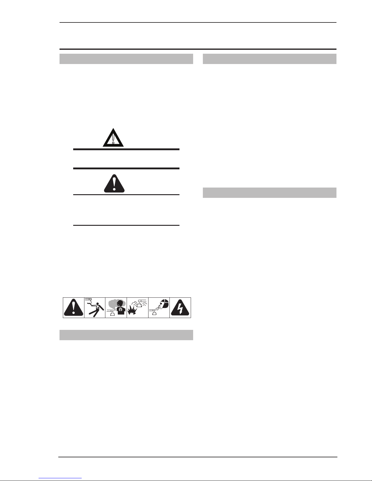
3.01 Duty Cycle
The rated duty cycle of a Welding Power Source, is a statement of the time it may be operated at its rated welding
current output without exceeding the temperature limits of the insulation of the component parts. To explain the
10 minute duty cycle period the following example is used. Suppose a Welding Power Source is designed to operate at a 20% duty cycle, 210 amperes at 24.5 volts. This means that it has been designed and built to provide the
rated amperage (210A) for 2 minutes, i.e. arc welding time, out of every 10 minute period (20% of 10 minutes is
2 minutes). During the other 8 minutes of the 10 minute period the Welding Power Source must idle and allowed
to cool. The thermal cut out will operate if the duty cycle is exceeded.
10 20 30 40 50 60 70 80 90 100 110 120 130 140 150 160 170 180 190 200 210 220
FABRICATOR 211i
Welding Current (AMPS)
SAFE OPERATING REGION
(MIG, TIG & STICK)
0
0
10
20
30
40
60
70
50
80
100
90
Duty Cycle (PERCENTAGE)
MIG
STICK / TIG
Art # A-10935
Figure 3-1: Fabricator 211i Duty Cycle on 230VAC
Welding Current (AMPS)
Duty Cycle (PERCENTAGE)
Art # A-10936
0
10
20
30
40
50
60
70
80
90
100
0102030405060708090100 110 120 130140 150
FABRICATOR 211i
SAFE OPERATING REGION
(MIG, TIG & STICK)
TIG
STICK
MIG
Figure 3-2: Fabricator 211i Duty Cycle on 110VAC
SECTION 3:
SAFETY AND INSTALLATION
Page 20

FABRICATOR 211i SAFETY/INSTALLATION
SAFETY/INSTALLATION 3-2 Manual 0-5226
3.02 Specifications
Description Fabricator 211i Multi Process Welding Inverter
Power Source Plant Part No. W1004206
Power Source Dimensions H435mm x W266mm x D617mm
Power Source Mass 26kg
Cooling Fan Cooled
Welder Type Multi Process Inverter Power Source
Applicable Standard EN 60974-1
Number of Phases Single Phase
Nominal Supply Voltage 230V±15% 110V±15%
Nominal Supply Frequency 50/60Hz 50/60Hz
Welding Current Range (MIG Mode) 10-210A 10-140A
Wirefeed Speed Range 2.5 - 18 MPM 2.5 - 18 MPM
Effective Input Current (I1eff) 15 Amps 19.6 Amps
Maximum Input Current (I1max) 30 Amps 39 Amps
Single Phase Generator Requirement 7 k VA 4.5 k VA
MIG (GMAW/FCAW) Welding Output, 40ºC, 10
min
210A @ 20%, 24.5V
130A @ 60%, 20.5V
101A @ 100%, 19.1V
140A @ 20%, 21V
99A @ 60%, 19V
77A @ 100%, 17.9V
STICK (MMA) Welding Output, 40ºC, 10 min. 200A @ 25%, 28.0V
130A @ 60%, 25.2V
101A @ 100%, 24.0V
125A @ 25%, 25.0V
80A @ 60%, 23.2V
60A @ 100%, 22.4V
TIG (GTAW) Welding Output, 40ºC, 10 min. 200A @ 25%, 18V
130A @ 60%, 15.2V
101A @ 100%, 14.0V
150A @ 35%, 16V
115A @ 60%, 14.6V
90A @ 100%, 13.6V
Open circuit voltage 79V
Protection Class IP23S
Table 3-1: Fabricator 211i Specifications
Note 1: The Effective Input Current should be used for the determination of cable size & supply requirements.
Note 2: Motor start fuses or thermal circuit breakers are recommended for this application. Check local requirements for your situation in this regard.
Note 3: Generator Requirements at the Maximum Output Duty Cycle.
NOTE
Additional safety precautions may be required when using unit in an environment with increased hazard of electric shock . Please refer to relevant local standards for further information prior to using in
such areas.
Due to variations that can occur in manufactured products, claimed performance, voltages, ratings, all
capacities, measurements, dimensions and weights quoted are approximate only. Achievable capacities
and ratings in use and operation will depend upon correct installation, use, applications, maintenance
and service.
3.03 Environment
This unit is designed for use in environments with increased hazard of electric shock as outlined in EN 60974.1.
Additional safety precautions may be required when using unit in an environment with increased hazard of electric
shock. Please refer to relevant local standards for further information prior to using in such areas.
Page 21
SAFETY/INSTALLATION FABRICATOR 211i
Manual 0-5226 3-3 SAFETY/INSTALLATION
A. Examples of environments with increased hazard of
electric shock are:
1. In locations in which freedom of movement
is restricted, so that the operator is forced to
perform the work in a cramped (kneeling, sitting or lying) position with physical contact with
conductive parts.
2. In locations which are fully or partially limited
by conductive elements, and in which there is
a high risk of unavoidable or accidental contact
by the operator.
3. In wet or damp hot locations where humidity
or perspiration considerably reduces the skin
resistance of the human body and the insulation
properties of accessories.
B. Environments with increased hazard of electric
shock do not include places where electrically conductive parts in the near vicinity of the operator, which can
cause increased hazard, have been insulated.
3.04 Location
Be sure to locate the welder according to the following
guidelines:
A. In areas, free from moisture and dust.
B. Ambient temperature between 0°C (32°F) to 40°C
(104°F).
C. In areas, free from oil, steam and corrosive gases.
D. In areas, not subjected to abnormal vibration or
shock.
E. In areas, not exposed to direct sunlight or rain.
F. Place at a distance of 1 foot or more from walls or
similar that could restrict natural air flow for cooling.
G. The enclosure design of this power source meets
the requirements of IP23S as outlined in EN 60529.
H. Precautions must be taken against the power source
toppling over. The power source must be located on
a suitable horizontal surface in the upright position
when in use.
WARNING
This equipment should be electrically connected by a qualified electrician.
3.05 Ventilation
!
WARNING
Since the inhalation of welding fumes can
be harmful, ensure that the welding area is
effectively ventilated.
3.06 Mains Supply Voltage
Requirements
The Mains supply voltage
should be within ± 15% of the rated Mains supply voltage. Too low of a supply voltage may cause poor welding
performance or wirefeeder malfunction. Too high of a
supply voltage will cause components to overheat and
possibly fail.
WARNING
The Fabricator 211i must be electrically
connected by a qualified electrical tradesperson. Damage to the PCA (Power Control
Assembly) could occur if 276 VAC or higher
is applied to the Primary Power Cable
50/60 Hz
Single Phase
Primary Supply
Lead Size
Minimum
Primary Current
Circuit Size
(Vin/Iin)
Minimum
Plug Size
Current & Duty Cycle
MIG TIG STICK
Yes 2.5mm² 230V/15A 15A 20%@210A 25%@200A 25%@200A
Yes 2.5mm² 110V/32A 20A 20%@140A 35%@150A 25%@125A
Table 3-2: Input Power Source Leads for Fabricator 211i
WARNING
ELECTRIC SHOCK can kill; SIGNIFICANT DC VOLTAGE is present after removal of input power. DO NOT
TOUCH live electrical parts.
Page 22
FABRICATOR 211i SAFETY/INSTALLATION
SAFETY/INSTALLATION 3-4 Manual 0-5226
SHUT DOWN welding power source, disconnect input
power employing lockout/tagging procedures. Lock-out/
tagging procedures consist of padlocking line disconnect switch in open position, removing fuses from fuse
box, or shutting OFF and red-tagging circuit breaker or
other disconnecting device.
Electrical Input Requirements
Operate the welding power source from a single-phase
50/60 Hz, AC power source. The Welding Power Source
must be:
•Correctlyinstalled,ifnecessary,byaqualiedelectrician.
• Correctly earthed (electrically) in accordance with
local regulations.
•Connectedtothecorrectsizepowerpoint,fuseand
primary supply lead based on Table 3-2.
WARNING
Any electrical work must be carried out by a
qualified Electrical Tradesperson.
3.07 Electrical Input Connections
WARNING
ELECTRIC SHOCK can kill; SIGNIFICANT
DC VOLTAGE is present after removal of
input power.
DO NOT TOUCH live electrical parts.
SHUT DOWN welding power source, disconnect input
power employing lockout/tagging procedures. Lock-out/
tagging procedures consist of padlocking line disconnect switch in open position, removing fuses from fuse
box, or shutting off and red-tagging circuit breaker or
other disconnecting device.
• Electrical Input Requirements
Operate the welding power source from a single-phase
50/60 Hz, AC power supply. The input voltage must
match one of the electrical input voltages shown on
the input data label on the unit nameplate. Contact the
local electric utility for information about the type of
electrical service available, how proper connections
should be made, and inspection required. The line disconnect switch provides a safe and convenient means
to completely remove all electrical power from the
welding power supply whenever necessary to inspect
or service the unit.
Do not connect an input (WHITE or BLACK) conductor
to the ground terminal.
Do not connect the ground (GREEN) conductor to an
input line terminal.
1. Connection end of ground (GREEN or GREEN/
YELLOW) conductor to a suitable ground. Use
a grounding method that complies with all applicable electrical codes.
2. Connect ends of active (BROWN) and Neutral
(BLUE) input conductors to a suitable power supply system that complies with all appliance local
electrical codes.
Input Power
Each unit incorporates an INRUSH circuit. When the
MAIN CIRCUIT SWITCH is turned on, the inrush circuit
provides pre-charging for the input capacitors. A relay
in the Main Power PCB1 will turn on after the input
capacitors have charged to operating voltage (after
approximately 5 seconds).
3.08 Electromagnetic Compatibility
!
WARNING
Extra precautions for Electromagnetic
Compatibility may be required when this
Welding Power Source is used in a domestic
situation.
A. Installation and Use - Users Responsibility
The user is responsible for installing and using the welding equipment according to the manufacturer’s instructions. If electromagnetic disturbances are detected then
it shall be the responsibility of the user of the welding
equipment to resolve the situation with the technical
assistance of the manufacturer. In some cases this remedial action may be as simple as earthing the welding
circuit, see NOTE below. In other cases it could involve
constructing an electromagnetic screen enclosing the
Welding Power Source and the work, complete with
associated input filters. In all cases, electromagnetic
disturbances shall be reduced to the point where they
are no longer Troublesome.
NOTE
The welding circuit may or may not be
earthed for safety reasons. Changing the
earthing arrangements should only be authorized by a person who is competent to
assess whether the changes will increase the
risk of injury, e.g. by allowing parallel welding current return paths which may damage
the earth circuits of other equipment.
Page 23

SAFETY/INSTALLATION FABRICATOR 211i
Manual 0-5226 3-5 SAFETY/INSTALLATION
B. Assessment of Area
Before installing welding equipment, the user shall make
an assessment of potential electromagnetic problems
in the surrounding area. The following shall be taken
into account.
1. Other supply cables, control cables, signalling and
telephone cables; above, below and adjacent to the
welding equipment.
2. Radio and television transmitters and receivers.
3. Computer and other control equipment.
4. Safety critical equipment, e.g. guarding of industrial
equipment.
5. The health of people around, e.g. the use of pacemakers and hearing aids.
6. Equipment used for calibration and measurement.
7. The time of day that welding or other activities are
to be carried out.
8. The immunity of other equipment in the environment:
the user shall ensure that other equipment being
used in the environment is compatible: this may
require additional protection measures.
The size of the surrounding area to be considered
will depend on the structure of the building and other
activities that are taking place. The surrounding area
may extend beyond the boundaries of the premises.
C. Methods of Reducing Electromagnetic Emissions
1. Mains Supply
Welding equipment should be connected to the
mains supply according to the manufacturer’s
recommendations. If interference occurs, it may
be necessary to take additional precautions such
as filtering of the mains supply. Consideration
should be given to shielding the supply cable
of permanently installed welding equipment in
metallic conduit or equivalent. Shielding should be
electrically continuous throughout its length. The
shielding should be connected to the Welding Power
Source so that good electrical contact is maintained
between the conduit and the Welding Power Source
enclosure.
2. Maintenance of Welding Equipment
The welding equipment should be routinely
maintained according to the manufacturer’s
recommendations. All access and service doors and
covers should be closed and properly fastened when
the welding equipment is in operation. The welding
equipment should not be modified in any way except
for those changes and adjustments covered in the
manufacturer’s instructions.
3. Welding Cables
The welding cables should be kept as short as
possible and should be positioned close together
but never coiled and running at or close to the floor
level.
4. Equipotential Bonding
Bonding of all metallic components in the welding
installation and adjacent to it should be considered.
However, metallic components bonded to the work
piece will increase the risk that the operator could
receive a shock by touching the metallic components
and the electrode at the same time. The operator
should be insulated from all such bonded metallic
components.
5. Earthing/grounding of the Work Piece
Where the work piece is not bonded to earth for
electrical safety, nor connected to earth because
of its size and position, e.g. ship’s hull or building
steelwork, a connection bonding the work piece to
earth may reduce emissions in some, but not all
instances. Care should be taken to prevent the earthing of the work piece increasing the risk of injury
to users, or damage to other electrical equipment.
Where necessary, the connection of the work piece
to earth should be made by direct connection to
the work piece, but in some countries where direct
connection is not permitted, the bonding should be
achieved by suitable capacitance, selected according
to national regulations.
6. Screening and Shielding
Selective screening and shielding of other cables
and equipment in the surrounding area may alleviate
problems of interference. Screening the entire
welding installation may be considered for special
applications.
Page 24
FABRICATOR 211i SAFETY/INSTALLATION
SAFETY/INSTALLATION 3-6 Manual 0-5226
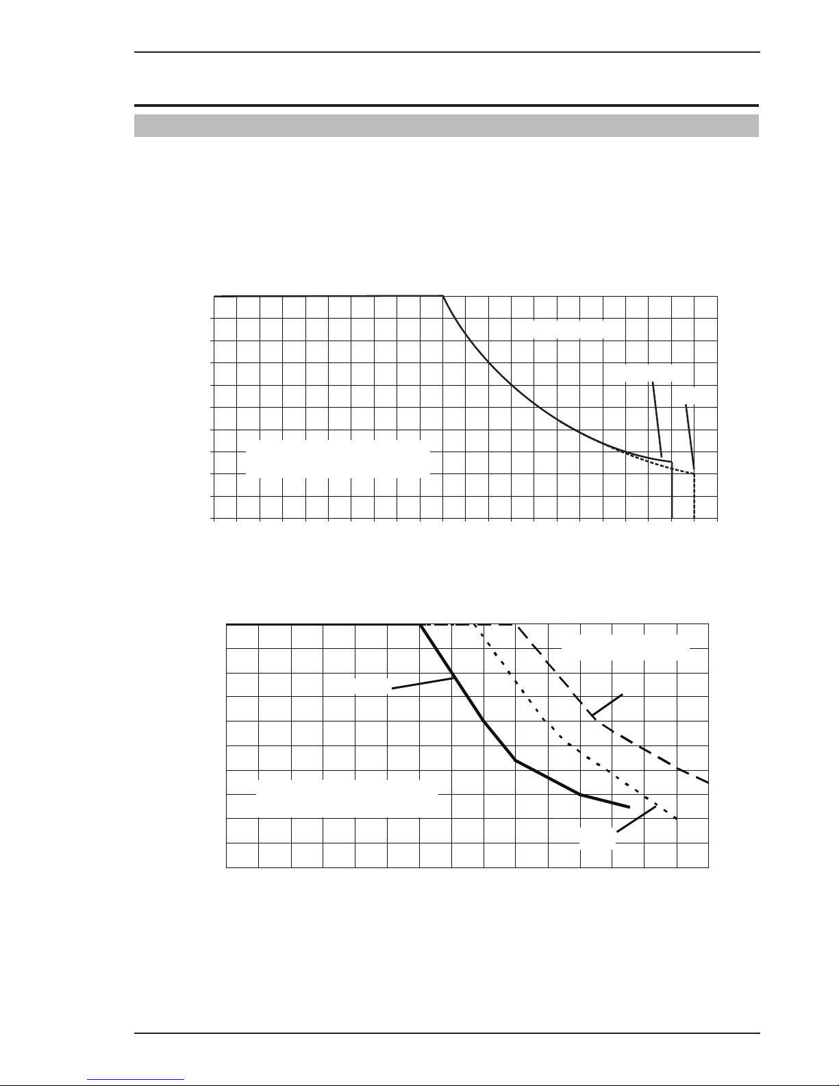
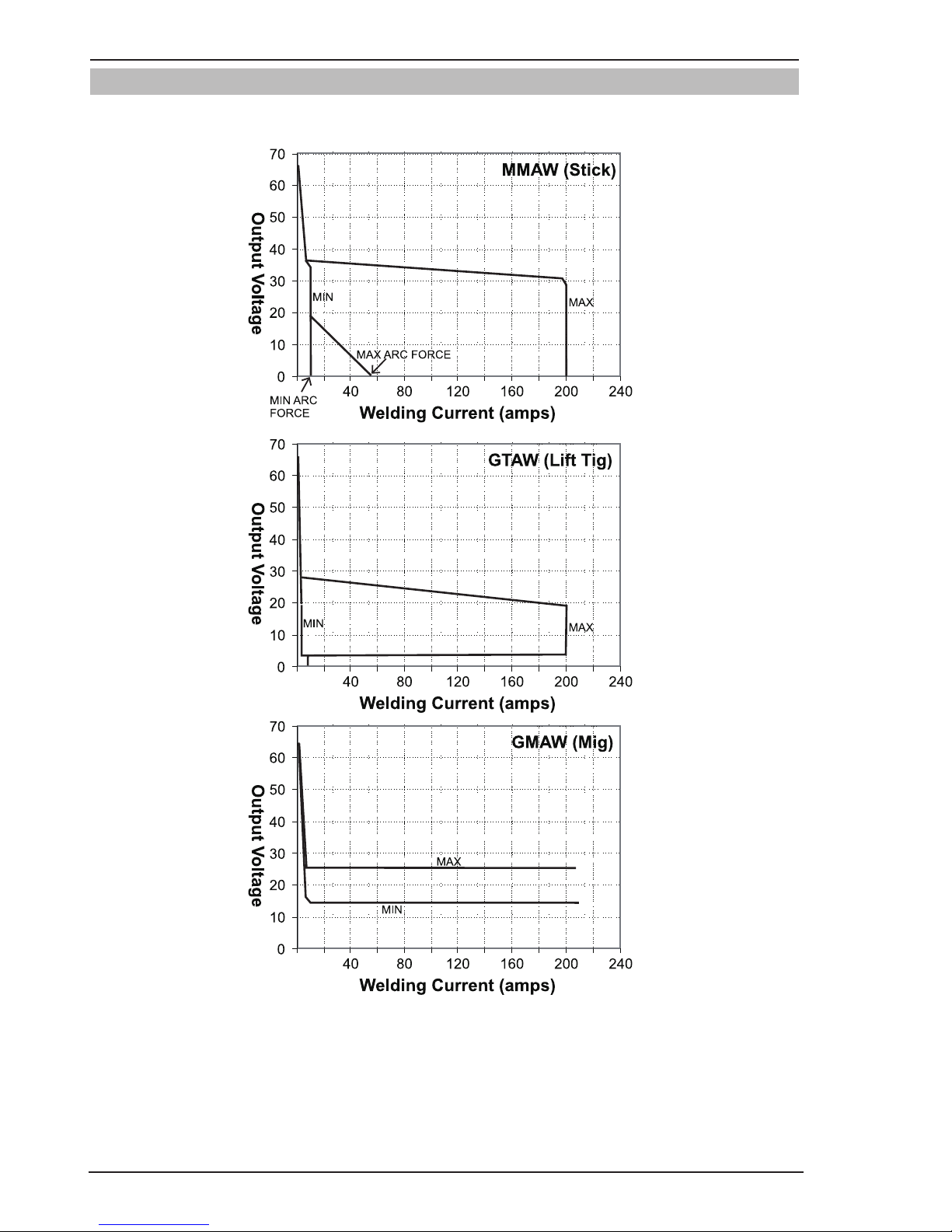
3.09 Volt-Ampere Curves
Voltage-Amperage Curves shows maximum voltage and amperage output capabilities of welding power source.
Curves of other settings fall between curves shown.
Art # A-10435_AB
Figure 3-3: Fabricator 211i Volt-Ampere Curves
Page 25
OPERATION FABRICATOR 211i
Manual 0-5226 4-1 OPERATION
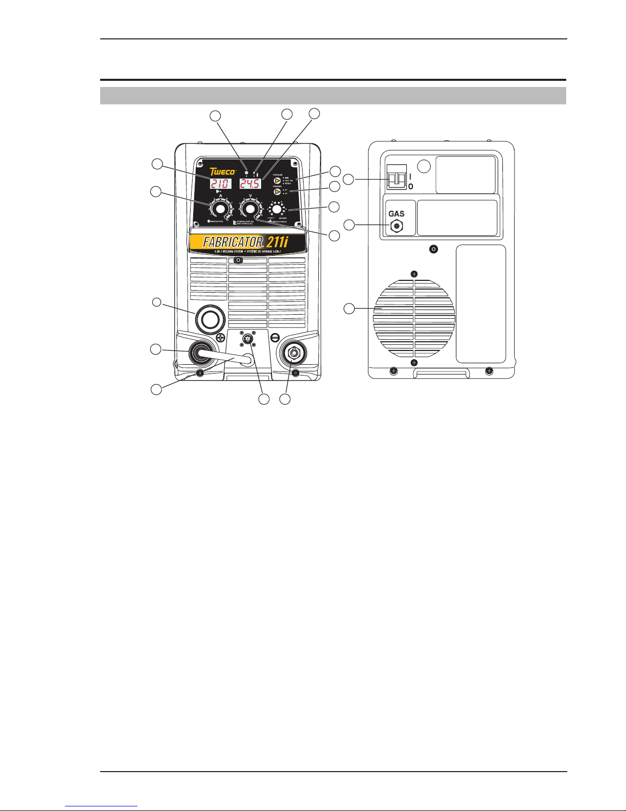
4.01 Power Source Controls, Indicators and Features
Art # A-10937_AB
3
4
5
6
7
89
11
10
12
13
2
1
14
16
15
21
Figure 4-1: Fabricator Front and Control Panel Figure 4-2: Fabricator Front Connections
1. Power Indicator
The power indicator is illuminated when the correct mains power is applied to the power source and when the
ON/OFF switch located on the rear panel is in the ON position.
2. Thermal Overload Indicator (Fault Indicator)
This welding power source is protected by a self resetting thermostat. The indicator will illuminate if the duty
cycle of the power source has been exceeded. Should the thermal overload indicator illuminate the output
of the power source will be disabled. Once the power source cools down this light will go OFF and the over
temperature condition will automatically reset. Note that the mains power switch should remain in the on
position such that the fan continues to operate thus allowing the unit to cool sufficiently. Do not switch the
unit off should a thermal overload condition be present.
3. Digital Amps Meter (Left Digital Display)
MIG Mode
This digital meter is used to display the pre-set (preview) Wirefeed Speed in Meters Per Minute (MPM) in
MIG mode and actual welding amperage of the power source when welding. At times of non-welding, the
digital meter will display a pre-set (preview) value of Wirefeed Speed. This value can be adjusted by varying
the Amperage Control Knob (4).
STICK and LIFT TIG Modes
The digital meter is used to display the pre-set (preview) amperage in STICK / LIFT TIG modes and actual
welding amperage of the power source when welding. At times of non-welding, the amperage meter will
display a pre-set (preview) value in both STICK and LIFT TIG modes. This value can be adjusted by varying
the Amperage Control Knob (4).
SECTION 4:
OPERATION
Page 26

FABRICATOR 211i OPERATION
OPERATION 4-2 Manual 0-5226
When welding, this digital meter will display actual welding amperage in all modes.
At the completion of welding, the digital meter will hold the last recorded amperage value for a period of
approximately 10 seconds in all modes. The amperage meter will hold the value until; (1) any of the front
panel controls are adjusted in which case the unit will revert to preview mode, (2) welding is recommenced,
in which case actual welding amperage will be displayed, or (3) a period of 10 seconds elapses following the
completion of welding in which case the unit will return to preview mode.
NOTE
The preview functionality provided on this power source is intended to act as a guide only. Some differences may be observed between preview values and actual welding values due to factors including
the mode of welding, differences in consumables/gas mixtures, individual welding techniques and the
transfer mode of the welding arc (ie dip versus spray transfer). Where exact settings are required (in
the case of procedural work), it is recommended that alternate measurement methods be utilized to
ensure output values are accurate.
4. Amperage Control (Wirespeed)
The amperage control knob adjusts the amount of welding current delivered by the power source. In STICK
(MMA) and LIFT TIG (GTAW) modes, the amperage control knob directly adjusts the power inverter to deliver
the desired level of output current. In MIG (GMAW/FCAW) mode, the amperage knob adjusts the speed of
the wire feed motor (which in turn adjusts the output current by varying the amount of MIG wire delivered
to the welding arc). The optimum wire speed required will dependent on the type of welding application. The
setup chart on the inside of the wire feed compartment door provides a brief summary of the required output
settings for a basic range of MIG welding applications.
NOTE
The preview functionality provided on this power source is intended to act as a guide only. Some differences may be observed between preview values and actual welding values due to factors including
the mode of welding, differences in consumables/gas mixtures, individual welding techniques and the
transfer mode of the welding arc (ie dip versus spray transfer). Where exact settings are required (in
the case of procedural work), it is recommended that alternate measurement methods be utilized to
ensure output values are accurate.
5. MIG Gun Adaptor (Euro Style)
The MIG gun adaptor is the connection point for the MIG welding gun. Connect the gun by pushing the gun
connector into the brass gun adaptor firmly and screwing the plastic nut clockwise to secure in position. To
remove the MIG gun simply reverse these directions.
6. Positive Welding Output Terminal
The positive welding terminal is used to connect the welding output of the power source to the appropriate
welding accessory such as the MIG gun (via the MIG polarity lead), electrode holder lead or work lead. Positive welding current flows from the power source via this heavy duty bayonet type terminal. It is essential,
however, that the male plug is inserted and turned securely to achieve a sound electrical connection.
CAUTION
Loose welding terminal connections can cause overheating and result in the male plug being fused in
the bayonet terminal.
7. MIG Polarity Lead
The polarity lead is used to connect the MIG gun to the appropriate positive or negative output terminal (allowing polarity reversal for different welding applications). In general, the polarity lead should be connected
in to the positive welding terminal (+) when using steel, stainless steel or aluminium electrode wire. When
using gasless wire, the polarity lead is generally connected to the negative welding terminal (-). If in doubt,
consult the manufacturer of the electrode wire for the correct polarity. It is essential, however, that the male
plug is inserted and turned securely to achieve a sound electrical connection.
Page 27

OPERATION FABRICATOR 211i
Manual 0-5226 4-3 OPERATION
CAUTION
Loose welding terminal connections can cause overheating and result in the male plug being fused in
the bayonet terminal.
8. Negative Welding Output Terminal
The negative welding terminal is used to connect the welding output of the power source to the appropriate
welding accessory such as the MIG gun (via the MIG polarity lead), TIG torch or work lead. Negative welding
current flows to the power source via this heavy duty bayonet type terminal. It is essential, however, that the
male plug is inserted and turned securely to achieve a sound electrical connection.
CAUTION
Loose welding terminal connections can cause overheating and result in the male plug being fused in
the bayonet terminal.
9. Remote Control Socket
The 8 pin Remote Control Socket is used to connect remote control devices to the welding power source. To
make connections, align keyway, insert plug, and rotate threaded collar fully clockwise.
Trigger Switch
Remote Wirespeed in MIG (GMAW/FCAW) mode
Remote Amps in LIFT TIG (GTAW) mode
Remote Volts in
MIG (GMAW/FCAW)
1
2
3
4
5
6
7
8
WV
3
4
5
6
7
8
1
2
Negative
Spool Gun Motor
Positive
Art # A-10421_AC
Figure 4-3: Remote Control Socket
Socket Pin
Function
1 Spool Gun Motor Negative
2
Trigger Switch Input
3
Trigger Switch Input
4
Spool Gun Motor Positive
5
5k ohm (maximum) connection to 5k ohm remote control potentiometer.
6
Zero ohm (minimum) connection to 5k ohm remote control potentiometer.
7
Wiper arm connection to 5k ohm remote control Wirespeed MIG (GMAW/FCAW) mode
potentiometer. Wiper arm connection to 5k ohm remote control Amps LIFT TIG (GTAW) mode
potentiometer.
8
Wiper arm connection to 5k ohm remote control Volts MIG (GMAW/FCAW) mode
potentiometer.
Table 4-1
Note that the local/ remote switch (item 18) located in the wirefeed compartment should be set to remote for
the amperage/voltage controls to be operative.
Page 28

FABRICATOR 211i OPERATION
OPERATION 4-4 Manual 0-5226
10. Multifunction Control - Voltage, Down Slope & Arc Force
The multifunction control knob is used to adjust Voltage (MIG Mode), Down slope (LIFT TIG Mode) and Arc
Force (STICK Mode) depending on the welding mode selected.
NOTE
The preview functionality provided on this power source is intended to act as a guide only. Some differences may be observed between preview values and actual welding values due to factors including
the mode of welding, differences in consumables/gas mixtures, individual welding techniques and the
transfer mode of the welding arc (ie dip versus spray transfer). Where exact settings are required (in
the case of procedural work), it is recommended that alternate measurement methods be utilised to
ensure output values are accurate.
When MIG (GMAW/FCAW) Mode is Selected
In this mode the control knob is used to adjust the output voltage of the unit. The welding voltage is increased
by turning the knob clockwise or decreased by turning the knob anti-clockwise. The optimum voltage level
required will dependent on the type of welding application. The setup chart on the inside of the wire feed
compartment door provides a brief summary of the required output settings for a basic range of MIG welding
applications.
When STICK (MMA) Mode is Selected
In this mode the multifunction control knob is used to adjust arc force. Arc force control provides an adjustable amount of welding force (or “dig”) control. This feature can be particularly beneficial in providing the
operator the ability to compensate for variability in joint fit-up in certain situations with particular electrodes.
In general increasing the arc force control toward ‘10’ (maximum arc force) allows greater penetration control
to be achieved. Arc force is increased by turning the control knob clockwise or decreased by turning the knob
anti-clockwise
When LIFT TIG Mode is Selected
In this mode the multifunction control knob is used to adjust down slope. Down slope allows the user to
select the ramp down time at the completion of the weld. The main function of down slope is to allow the
welding current to be gradually reduced over a pre-set time frame such that the welding pool is given time
to cool sufficiently.
Note that when in 2T normal mode (refer item 12), the unit will enter down slope mode as soon as the trigger
switch is released (ie if the multifunction control knob is set to 5, the unit will ramp down from the present
welding current to zero over 5 seconds). If no down slope time is selected then the welding output will cease
immediately. If the unit is set to 4T latch mode, to enter down slope mode the trigger must be held in for the
selected time period (ie press and release trigger to commence welding, then press and hold trigger again to
enter down slope mode). Should the trigger be released during the down slope phase (4T only), the output
will cease immediately.
11. Arc Control (Inductance)
The arc control operates in MIG (GMAW/FCAW) mode only and is used to adjust the intensity of the welding
arc. Lower arc control settings make the arc softer with less weld spatter. Higher arc control settings give a
stronger driving arc which can increase weld penetration.
12. Trigger Mode Control (MIG and LIFT TIG Mode only)
The trigger mode control is used to switch the functionality of the torch trigger between 2T (normal) and 4T
(latch mode)
2T Normal Mode
In this mode, the torch trigger must remain depressed for the welding output to be active. Press and hold the
torch trigger to activate the power source (weld). Release the torch trigger switch to cease welding.
Page 29

OPERATION FABRICATOR 211i
Manual 0-5226 4-5 OPERATION
4T Latch Mode
This mode of welding is mainly used for long welding runs to reduce operator fatigue. In this mode the operator can press and release the torch trigger and the output will remain active. To deactivate the power source,
the trigger switch must again be depressed and realised, thus eliminating the need for the operator to hold
the torch trigger.
Note that when operating in LIFT TIG (GTAW) mode, the power source will remain activated until the selected
downslope time has elapsed (refer Item 10).
13. Process Selection Control
The process selection control is used to select the desired welding mode. Three modes are available, MIG
(GMAW/FCAW), LIFT TIG (GTAW) and STICK (MMA) modes. Refer to section 4.10 or 4.11 for MIG (GMAW/
FCAW) set up details, section 4.12 for LIFT TIG (GTAW) set-up details or section 4.13 for STICK (MMA) setup details.
Note that when the unit is powered off the mode selection control will automatically default to MIG mode.
This is necessary so as to prevent inadvertent arcing should an electrode holder be connected to the unit and
mistakenly be in contact with the work piece during power up.
14. Digital Voltage Meter (Right Digital Display)
MIG Mode
This digital meter is used to display the pre-set (preview) Voltage in MIG mode and actual welding voltage
of the power source when welding. At times of non-welding, the digital meter will display a pre-set (preview)
value of Voltage. This value can be adjusted by varying the Multifunction Control Knob (10).
STICK and LIFT TIG Modes
This digital meter is used to display the Welding Output Terminal Voltage in STICK / LIFT TIG modes during
non-welding or welding. This value cannot be adjusted by varying the Multifunction Control Knob (10).
When welding, this digital meter will display actual welding voltage in all modes.
At the completion of welding, the digital meter will hold the last recorded voltage value for a period of approximately 10 seconds in all modes. The voltage meter will hold the value until; (1) any of the front panel controls
are adjusted in which case the unit will revert to preview mode, (2) welding is recommenced, in which case
actual welding amperage will be displayed, or (3) a period of 10 seconds elapses following the completion of
welding in which case the unit will return to preview mode.
NOTE
The preview functionality provided on this power source is intended to act as a guide only. Some differences may be observed between preview values and actual welding values due to factors including
the mode of welding, differences in consumables/gas mixtures, individual welding techniques and the
transfer mode of the welding arc (ie dip versus spray transfer). Where exact settings are required (in
the case of procedural work), it is recommended that alternate measurement methods be utilized to
ensure output values are accurate.
15. Gas Inlet (MIG mode only)
The Gas Inlet connection is used to supply the appropriate MIG welding gas to the unit. Refer to section 4.10
set up details.
!
WARNING
Only Inert Shielding Gases specifically designed for welding applications should be used.
Page 30

FABRICATOR 211i OPERATION
OPERATION 4-6 Manual 0-5226
16. On / Off Switch
This Single Phase circuit breaker performs a dual function.
It is used to turn the unit on/off and it will also trip in the event of a fault.
WARNING
When the front digital displays are lit, the machine is connected to the Mains supply voltage and the
internal electrical components are at Mains voltage potential.
Art # A-10938
17
Figure 4-4: Wire Feed Compartment Control
17. Wiredrive Motor Circuit Breaker
The 4A Circuit Breaker protects the unit from electrical faults and will operate in the event of a motor overload.
NOTE
If a circuit breaker trips, a short cooling period must be allowed before an attempt is made to reset the
unit by pressing the circuit breaker reset button
.
18. Local / Remote Switch (located in wirefeed compartment)
The local/ remote switch is used only when a remote control device (such as a TIG torch with remote current
control) is fitted to the unit via the remote control socket (item 9). When the local/ remote switch is in the
remote position, the unit will detect a remote device and work accordingly. When in the local mode, the unit
will not detect the remote device and will operate from the power source controls only. Note that the trigger
will operate at all times on the remote control socket irrespective of the position of the local/ remote switch
(ie in both local and remote modes).
Should a remote device be connected and the local/ remote switch set to remote, the maximum setting of
the power source will be determined by the respective front panel control, irrespective of the remote control
device setting. As an example, if the output current on the power source front panel is set to 50% and the
remote control device is set to 100%, the maximum achievable output from the unit will be 50%. Should 100%
output be required, the respective front panel control must be set to 100%, in which case the remote device
will then be able to control between 0-100% output.
Page 31

OPERATION FABRICATOR 211i
Manual 0-5226 4-7 OPERATION
19. Burnback Control (located in wirefeed compartment)
The burnback control is used to adjust the amount of MIG wire that protrudes from the MIG gun after the
completion of MIG welding (commonly referred to as stick out). To decrease the burnback time (or lengthen
the amount of wire protruding from the MIG gun at the completing of welding), turn the burnback control
knob anti clockwise. To increase the burnback time (or shorten the amount of wire protruding from the MIG
gun at the completing of welding), turn the Burnback Control knob clockwise.
20. MIG Gun/ SPOOL Gun Switch (located in wirefeed compartment)
The MIG Gun / SPOOL Gun switch is used to switch welding mode between MIG Gun functionality and SPOOL
Gun functionality.
21. Cooling Fan
The Fabricator 211i is fitted with a fan as needed feature. Fan as needed automatically switches the cooling
fan off when it is not required. This has two main advantages; (1) to minimize power consumption, and (2) to
minimise the amount of contaminants such as dust that are drawn into the power source.
Note that the fan will only operate when required for cooling purposes and will automatically switch off when
not required.
4.02 Attaching MIG Gun
Fit the MIG gun to the power source by pushing the MIG gun connector into the MIG gun adaptor and screwing
the plastic nut clockwise to secure the MIG gun to the MIG gun adaptor.
MIG Gun Adaptor
MIG Gun Connector
Art # A-10423_AB
Figure 4-5: Attaching MIG Gun
Page 32

FABRICATOR 211i OPERATION
OPERATION 4-8 Manual 0-5226
4.03 Installing 15kg Spool (300mm diameter)
As delivered from the factory, the unit is fitted with a Wire Spool Hub which accepts a Spool of 300mm diameter.
Remove the locking pin from the spool hub. Install the wire spool over the spool hub, locating the hole in the
spool, with the alignment pin on the spool hub.Insert the locking pin back into the spool hub.
Wire Spool
Hub Nut
Spring
300mm
Wire Spool
Retaining Clip
Use inner holes on
Spool Hub
Flat Washer
Small Hole
Fibre Washer
Spool Hub
Keyed Washer
Flat Washer
Large Hole
Pin
Art # A-10939
Figure 4-6: 300mm 15kg Spool Installation
4.04 Installing 5kg Spool (200mm diameter)
Remove the locking pin from the spool hub.
Install the 5kg Spool over the spool hub, locating the hole in the 5kg Spool, with the alignment pin on the Spool Hub.
Insert the locking pin back into the spool hub, in the “rear” position, as shown, ensuring the wire spool is firmly
secured in position.
Wire Spool
Hub Nut
Spring
200mm
Wire Spool
Retaining Clip
Use inner holes on
Spool Hub
Flat Washer
Small Hole
Fibre Washer
Spool Hub
Keyed Washer
Flat Washer
Large Hole
Pin
Art # A-10940
Figure 4-7: 200mm 5kg Spool Installation
Page 33

OPERATION FABRICATOR 211i
Manual 0-5226 4-9 OPERATION
4.05 Inserting Wire into the Wire Feed Mechanism
Release the tension from the pressure roller by turning the adjustable wire drive tension screw in an anti-clockwise
direction. Then to release the pressure roller arm push the tension screw toward the front of the machine which
releases the pressure roller arm (Figure 4-8). With the MIG welding wire feeding from the bottom of the spool
(Figure 4-9) pass the electrode wire through the inlet guide, between the rollers, through the outlet guide and into
the MIG gun. Re-secure the pressure roller arm and wire drive tension screw and adjust the pressure accordingly
(Figure 4-8). Remove the contact tip from the MIG gun. With the MIG gun lead reasonably straight, feed the wire
through the MIG gun by depressing the trigger switch. Fit the appropriate contact tip.
WARNING
Before connecting the work clamp to the work make sure the mains power supply is switched off.
The electrode wire will be at welding voltage potential while it is being feed through the system.
Keep MIG gun away from eyes and face.
Wire Drive Tension Screw
Pressure Roller Arm
Outlet Guide
Inlet Guide
Art # A-10426
Figure 4-8: Wire Drive Assembly Components
MIG Welding Wire
Art # A-10427_AB
Figure 4-9: MIG Welding Wire - Installation
Page 34

FABRICATOR 211i OPERATION
OPERATION 4-10 Manual 0-5226
4.06 Feed Roller Pressure Adjustment
The pressure (top) roller applies pressure to the grooved feed roller via an adjustable pressure screw. These
devices should be adjusted to a minimum pressure that will provide satisfactory WIREFEED without slippage. If
slipping occurs, and inspection of the wire contact tip reveals no wear, distortion or burn back jam, the conduit
liner should be checked for kinks and clogging by metal flakes and swarf. If it is not the cause of slipping, the feed
roll pressure can be increased by rotating the pressure screw clockwise.
WARNING
Before changing the feed roller ensure that the mains supply to the power source is switched off.
CAUTION
The use of excessive pressure may cause rapid wear of the feed rollers, shafts and bearing.
4.07 Changing the Feed Roll
To change feed roll remove the feed roll retaining screw by turning in an anticlockwise direction. Once the feed
roll is removed then to replace feed roll simply reverse these directions.
A dual groove feed roller is supplied as standard. It can accommodate 0.6/0.8mm diameter hard wires. Select the
roller required with the chosen wire size marking facing outward.
GROOVE “B”GROOVE “A”
GROOVE “A” SI
ZE
GROOVE “B” SIZE
A-09583
Figure 4-10: Dual Groove Feed Roller
Feed Roll Retaining Screw
Art # A-10428
Figure 4-11: Changing the Feed Roll
Page 35

OPERATION FABRICATOR 211i
Manual 0-5226 4-11 OPERATION
4.08 Wire Reel Brake
The wire reel hub incorporates a friction brake which is adjusted during manufacture for optimum braking.
If it is considered necessary, adjustment can be made by turning the Thumb Screw inside the open end of the hub
clockwise to tighten the brake. Correct adjustment will result in the wire reel circumference continuing no further
than 10-20mm after release of the trigger. The electrode wire should be slack without becoming dislodged from
wire spool.
CAUTION
Overtension of brake will cause rapid wear of mechanical WIREFEED parts, overheating of electrical
componentry and possibly an increased incidence of electrode wire Burnback into contact tip.
Spool Hub Tension
Thumb Screw
Art # A-10429
Figure 4-12: Wire Reel Brake
4.09 Setup for MIG (GMAW) Welding with Gas Shielded MIG Wire
A. Select MIG mode with the process selection control. (refer to Section 4.01.13 for further information)
B. Connect the MIG polarity lead to the positive welding terminal (+). If in doubt, consult the electrode wire manu-
facturer. Welding current flows from the Power Source via heavy duty bayonet type terminals. It is essential,
however, that the male plug is inserted and turned securely to achieve a sound electrical connection.
C. Fit the MIG gun to the power source. (Refer to section 4.02 Attaching MIG gun).
D. Connect the work lead to the negative welding terminal (-). If in doubt, consult the electrode wire manufacturer.
Welding current flows from the Power Source via heavy duty bayonet type terminals. It is essential, however,
that the male plug is inserted and turned securely to achieve a sound electrical connection.
E. Fit the welding grade shielding gas regulator/flowmeter to the shielding gas cylinder, then connect the shielding
gas hose from the rear of the power source to the regulator/flowmeter outlet.
F. Refer to the Weld Guide located on the inside of the wirefeed compartment door for further information.
WARNING
Before connecting the work clamp to the work make sure the mains power supply is switched off.
Secure the welding grade shielding gas cylinder in an upright position by chaining it to a suitable stationary support to prevent falling or tipping.
Page 36

FABRICATOR 211i OPERATION
OPERATION 4-12 Manual 0-5226
CAUTION
Loose welding terminal connections can cause overheating and result in the male plug being fused in
the terminal.
Remove any packaging material prior to use. Do not block the air vents at the front or rear of the Welding Power Source.
Shielding Gas Hose Fitted with Quick Connect
Positive Welding
Terminal (+)
MIG Polarity Lead
MIG Gun
Work Lead
Negative Welding
Terminal (-)
Art # A-10430_AB
Figure 4-13: Setup for MIG Welding with Gas Shielded MIG Wire
Page 37

OPERATION FABRICATOR 211i
Manual 0-5226 4-13 OPERATION
4.10 Setup for MIG (FCAW) Welding with Gasless MIG Wire
A. Select MIG mode with the process selection control (refer to Section 4.01.13 for further information).
B. Connect the MIG polarity lead to the negative welding terminal (-). If in doubt, consult the electrode wire manu-
facturer. Welding current flows from the power source via heavy duty bayonet type terminals. It is essential,
however, that the male plug is inserted and turned securely to achieve a sound electrical connection.
C. Connect the work lead to the positive welding terminal (+). If in doubt, consult the electrode wire manufacturer.
Welding current flows from the power source via heavy duty bayonet type terminals. It is essential, however,
that the male plug is inserted and turned securely to achieve a sound electrical connection.
D. Refer to the Weld Guide located on the inside of the wirefeed compartment door for further information.
WARNING
Before connecting the work clamp to the work make sure the mains power supply is switched off.
CAUTION
Loose welding terminal connections can cause overheating and result in the male plug being fused in
the terminal.
Remove any packaging material prior to use. Do not block the air vents at the front or rear of the Welding Power Source.
MIG Gun
Work Lead
Positive Welding
Terminal (+)
Negative Welding
Terminal (-)
MIG Polarity Lead
Art # A-10431_AB
Figure 4-14: Setup for MIG Welding with Gasless MIG Wire
Page 38

FABRICATOR 211i OPERATION
OPERATION 4-14 Manual 0-5226
4.11 Setup for SPOOL GUN MIG (GMAW) Welding with Gas Shielded MIG Wire
A. Select MIG mode with the process selection control (refer to Section 4.01.13 for further information).
B. Connect the MIG polarity lead to the positive welding terminal (+). If in doubt, consult the electrode wire manu-
facturer. Welding current flows from the Power Source via heavy duty bayonet type terminals. It is essential,
however, that the male plug is inserted and turned securely to achieve a sound electrical connection.
C. Fit the Euro Spool Gun to the power source using the front panel EURO adaptor (refer also to section 4.02
Attaching MIG gun). Connect the 8 pin Remote Control Plug to the 8 pin Remote Control Socket on the power
source.
D. Connect the work lead to the negative welding terminal (-). If in doubt, consult the electrode wire manufacturer.
Welding current flows from the Power Source via heavy duty bayonet type terminals. It is essential, however,
that the male plug is inserted and turned securely to achieve a sound electrical connection.
E. Fit the welding grade shielding gas regulator/flowmeter to the shielding gas cylinder, then connect the shielding
gas hose from the rear of the power source to the regulator/flowmeter outlet.
F. Refer to the Weld Guide located on the inside of the wirefeed compartment door for further information.
G. Select MIG mode with the process selection control (refer to section 4.01.13 for further information).
H. Set the Spool Gun Switch located inside the wire drive compartment, to SPOOL GUN.
WARNING
Before connecting the work clamp to the work make sure the main power supply is switched off.
Secure the welding grade shielding gas cylinder in an upright position by chaining it to a suitable stationary support to prevent falling or tipping.
CAUTION
Loose welding terminal connections can cause overheating and result in the male plug being fused in
the terminal. Remove any packing material prior to use. Do not block the air vents at the front or rear
of the Welding Power Source.
Negative Welding
Te rminal (-)
Work Lead
Spool Gun
Positive Welding
Terminal (+)
Shielding Gas Hose Fitted with Quick Connect
MIG polarity lead
Spool Gun Switch
Remote Control
Socket
Art # A-10576
Figure 4-15: Setup for Spool Gun Welding with Gas Shielded MIG Wire
Page 39

OPERATION FABRICATOR 211i
Manual 0-5226 4-15 OPERATION
4.12 Setup for TIG (GTAW) Welding
A. Select LIFT TIG mode with the process selection control (refer to Section 4.01.13 for further information).
B. Connect the TIG Torch to the negative welding terminal (-). Welding current flows from the power source via
heavy duty bayonet type terminals. It is essential, however, that the male plug is inserted and turned securely
to achieve a sound electrical connection.
C. Connect the work lead to the positive welding terminal (+). Welding current flows from the Power Source via
heavy duty bayonet type terminals. It is essential, however, that the male plug is inserted and turned securely
to achieve a sound electrical connection.
D. Connect the TIG torch trigger switch via the 8 pin socket located on the front of the power source as shown
below. The TIG torch will require a trigger switch to operate in LIFT TIG Mode.
NOTE
If the TIG torch has a remote TIG torch current control fitted then it will require to be connected to the
8 pin socket. (Refer to section 4.01.9 Remote Control Socket for further information).
E. Fit the welding grade shielding gas regulator/flowmeter to the shielding gas cylinder then connect the shielding
gas hose from the TIG torch to the regulator/flowmeter outlet. Note that the TIG torch shielding gas hose is
connected directly to the regulator/flowmeter. The power source is not fitted with a shielding gas solenoid to
control the gas flow in LIFT TIG mode therefore the TIG torch will require a gas valve.
WARNING
Before connecting the work clamp to the work and inserting the electrode in the TIG Torch make sure
the mains power supply is switched off.
Secure the welding grade shielding gas cylinder in an upright position by chaining it to a stationary
support to prevent falling or tipping.
CAUTION
Remove any packaging material prior to use. Do not block the air vents at the front or rear of the Welding Power Source.
Loose welding terminal connections can cause overheating and result in the male plug being fused in
the terminal.
Page 40

FABRICATOR 211i OPERATION
OPERATION 4-16 Manual 0-5226
Positive Welding
Terminal (+)
Negative Welding
Terminal (-)
Work Lead
TIG Torch
TIG Remote Control
Art # A-10432_AB
Figure 4-16: Setup for TIG Welding
Page 41

OPERATION FABRICATOR 211i
Manual 0-5226 4-17 OPERATION
4.13 Setup for STICK (MMA) Welding
A. Connect the Electrode Holder lead to the positive welding terminal (+). If in doubt, consult the electrode manu-
facturer. Welding current flows from the Power Source via heavy duty bayonet type terminals. It is essential,
however, that the male plug is inserted and turned securely to achieve a sound electrical connection.
B. Connect the work lead to the negative welding terminal (-). If in doubt, consult the electrode manufacturer.
Welding current flows from the power source via heavy duty bayonet type terminals. It is essential, however,
that the male plug is inserted and turned securely to achieve a sound electrical connection.
C. Select STICK mode with the process selection control (refer to Section 4.01.13 for further information).
WARNING
Before connecting the work clamp to the work and inserting the electrode in the electrode holder make
sure the mains power supply is switched off.
CAUTION
Remove any packaging material prior to use. Do not block the air vents at the front or rear of the
Welding Power Source.
Positive Welding
Terminal (+)
Negative Welding
Terminal (-)
Work Lead
Electrode Holder
Art # A-10433
Figure 4-17: Setup for Manual Arc Welding
Page 42

FABRICATOR 211i OPERATION
OPERATION 4-18 Manual 0-5226
4.14 Leak Testing the System
Leak test the system before putting into operation.
1. Be sure that there is a valve in the downstream equipment to turn off the gas flow.
2. With the cylinder valve open, adjust the regulator to deliver the maximum required delivery flow rate.
3. Close the cylinder valve. Watch to see if the high pressure or contents gauge drops, if it does you have a
leak in the connection between the regulator and the cylinder.
4. Once leak testing has been performed and there are no leaks in the system, slowly open the cylinder valve
and proceed.
!
WARNING
If a leak has been detected anywhere in the system, dis continue use and have the system repaired.
DO NOT use leaking equipment. Do not attempt to repair a leaking system while the system is under
pressure..
Page 43

TROUBLESHOOTING FABRICATOR 211i
Manual 0-5226 5-1
TROUBLESHOOTING
5.01 Basic Troubleshooting-Power Source Faults
The following table is a guide for analysing problems and making repairs to the Power Source.
Fault Possible Cause Remedy
1 There is no weld
output and all front
panel displays are off
A
B
C
D
E
F
G
The main Power Switch is set to OFF
Line fuse is blown
The main Power Switch is faulty
Loose connection to EMC board
Faulty Power Inverter board
Faulty Control board
Faulty Display board
A
B
C
D
E
F
G
Set main Power Switch to ON
Replace Line fuse
Replace main Power Switch
Tighten connections
Replace Power Inverter board
Replace Control board
Replace Display board
2 There is no weld
output and all front
panel displays are off
or flickering on & off
A The internal protection circuit to shut
the unit down if the mains supply
voltage is too high has operated
A Check to see if mains supply
voltage is <274VAC. A
generator with poor voltage
regulation may cause a supply
voltage in excess of 274VAC.
Connect Power Source to a
supply voltage <274VAC.
3
There is no weld
output and the yellow
over temperature light
is on
A
B
C
Unit has overheated
Airflow inlet or outlet ducts are
blocked
Fan does not operate
A
B
C
Allow unit to cool with fan
running until over temperature
light extinguishes
Remove blockages from
airflow ducts
Replace fan. Check fan wiring
header is plugged securely
into Control board. Check fan
wiring is not damaged
4 Mode switch does not
change welding mode
A Faulty Display board A Replace Display board
5 The wirefeed motor
and the weld output
do not operate when
the torch trigger
switch is depressed
A
B
C
D
E
F
G
H
Internal wiring fault
Over temperature light is on
Power Source set to REMOTE
Trigger wires shorted to weld voltage
inside torch
Trigger wires or torch switch faulty
Faulty Power Inverter board
Faulty Control board
Faulty Display board
A
B
C
D
E
F
G
H
Check continuity of internal
wiring from Torch adaptor
through to boards
Allow unit to cool
Set switch to LOCAL
Repair trigger wires in torch
Check & Repair
Replace Power Inverter board
Replace Control board
Replace Display board
6 The wirefeed motor
does not operate
when the torch trigger
switch is depressed
A
B
C
D
Power Source set to TIG or STICK
mode
Wirefeeder motor wiring has become
loose
Trigger wires or torch switch faulty
Faulty Power Inverter board
A
B
C
D
Set power Source to MIG mode
Check motor wiring
Check & Repair
Replace Power Inverter board
7 The wirefeed motor
operates at maximum
speed and cannot be
adjusted.
A BFaulty Power Inverter board
Faulty Display board
A BReplace Power Inverter board
Replace Display board
Table 5-1 Power Source Faults
SECTION 5:
TROUBLESHOOTING
Page 44

TROUBLESHOOTING
5-2 Manual 0-5226
FABRICATOR 211i TROUBLESHOOTING
The following table is a guide for analysing problems and making repairs to the Power Source
Fault Possible Cause Remedy
8 Wirefeed motor operates
when the torch trigger
switch is depressed but the
gas valve does not operate.
A
B
C
D
E
Internal wiring fault
Faulty Solenoid
Impurity in gas system causing
solenoid to stay open or closed
Faulty Power Inverter board
Faulty Control board
A
B
C
D
E
Check solenoid wiring header is
plugged securely into Control
board. Check solenoid wiring is
not damaged
Replace Solenoid
Clean out gas system.
Disassemble solenoid & clean
out impurities
Replace Power Inverter board
Replace Control board
9 A welding arc can be
established but the weld is
erratic or inconsistent
A
B
C
D
E
F
G
H
Work Lead cable too small
Loose welding connections
Loose earth clamp
Incorrect weld polarity selected
No shielding gas
Wind blows shielding gas away
Incorrect TIG tungsten electrode
Poorly prepared or worn TIG
tungsten
A
B
C
D
E
F
G
H
Use correct weld cable size
Tighten welding connections
Tighten earth clamp
Correct weld polarity. Refer to
weld consumable manufacturers
recommended polarity
Connect shielding gas
Shield welding area from
draughts
Use correct tungsten type
Regrind tungsten to correct
shape
Table 5-2 Power Source Faults
5.02 Routine Service and Calibration Requirements
WARNING
There are extremely dangerous voltage and power levels present inside this Inverter Power Source.
Do not attempt to open or repair unless you are an accredited Tweco Service Provider. Disconnect the
Welding Power Source from the Mains Supply Voltage before disassembling.
Routine Inspection, Testing & Maintenance
The inspection and testing of the power source and associated accessories shall be carried out by a licensed
electrician. This includes an insulation resistance test and an earthing test to ensure the integrity of the unit is
compliant with Tweco's original specifications.
A. Testing Schedule
1. For transportable equipment, at least once every 3 months; and
2. For fixed equipment, at least once every 12 months.
The owners of the equipment shall keep a suitable record of the periodic tests and a system of tagging, including the date of the most recent inspection.
A transportable power source is deemed to be any equipment that is not permanently connected and fixed in
the position in which it is operated.
NOTE
Please refer to local guidelines for further information.
Page 45

TROUBLESHOOTING FABRICATOR 211i
Manual 0-5226 5-3
TROUBLESHOOTING
B. Insulation Resistance
Minimum insulation resistance for in-service Tweco Inverter Power Sources shall be measured at a voltage
of 500V between the parts referred to in Table 5-3 below. Power sources that do not meet the insulation resistance requirements set out below shall be withdrawn from service and not returned until repairs have been
performed such that the requirements outlined below are met.
Components to be Tested
Minimum Insulation
Resistance (MΩ)
Input circuit (including any connected control circuits) to welding circuit
(including any connected control circuits)
5
All circuits to exposed conductive parts
2.5
Welding circuit (including any connected control circuits) to any auxiliary
circuit which operates at a voltage exceeding extra low voltage
10
Welding circuit (including any connected control circuits) to any auxiliary
circuit which operates at a voltage not exceeding extra low voltage
1
Separate welding circuit to separate welding circuit
1
Table 5-3: Minimum Insulation Resistance Requirements: Tweco Inverter Power Sources
C. Earthing
The resistance shall not exceed 1Ω between any metal of a power source where such metal is required to be
earthed, and -
1. The earth terminal of a fixed power source; or
2. The earth terminal of the associated plug of a transportable power source
Note that due to the dangers of stray output currents damaging fixed wiring, the integrity of fixed wiring supplying Tweco welding power sources should be inspected by a licensed electrical worker in accordance with
the requirements below -
1. For outlets/wiring and associated accessories supplying transportable equipment - at least once every
3 months; and
2. For outlets/wiring and associated accessories supplying fixed equipment - at least once every 12 months.
D. General Maintenance Checks
Welding equipment should be regularly checked by an accredited Tweco Service Provider to ensure that:
1. Flexible cord is of the multi-core tough rubber or plastic sheathed type of adequate rating, correctly
connected and in good condition.
2. Welding terminals are in suitable condition and are shrouded to prevent inadvertent contact or short
circuit.
3. The Welding System is clean internally, especially from metal filing, slag, and loose material.
E. Accessories
Accessory equipment, including output leads, electrode holders, torches, wire feeders and the like shall be
inspected at least monthly by a competent person to ensure that the equipment is in a safe and serviceable
condition. All unsafe accessories shall not be used.
F. Repairs
If any parts are damaged for any reason, it is recommended that replacement be performed by an accredited
Tweco Service Provider.
Page 46
TROUBLESHOOTING
5-4 Manual 0-5226
FABRICATOR 211i TROUBLESHOOTING
Power Source Calibration
A. Schedule
Output testing of all Tweco Inverter Power Sources and applicable accessories shall be conducted at regular
intervals to ensure they fall within specified levels. Calibration intervals shall be as outlined below -
1. For transportable equipment, at least once every 3 months; and
2. For fixed equipment, at least once every 12 months.
If equipment is to be used in a hazardous location or environments with a high risk of electrocution as outlined
in EN 60974-1, then the above tests should be carried out prior to entering this location.
B. Calibration Requirements
Where applicable, the tests outlined in Table 5-4 below shall be conducted by an accredited Tweco service agent.
Testing Requirements
Output current (A) to be checked to ensure it falls within applicable Tweco power source specifications
Output Voltage (V) to be checked to ensure it falls within applicable Tweco power source specifications
Motor Speed (RPM) of wire drive motors to be checked to ensure it falls within required Tweco power
source / wire feeder specifications
Accuracy of digital meters to be checked to ensure it falls within applicable Tweco power source specifications
Table 5-4: Calibration Parameters
Periodic calibration of other parameters such as timing functions are not required unless a specific fault has
been identified.
C. Calibration Equipment
All equipment used for Power Source calibration shall be in proper working condition and be suitable for
conducting the measurement in question. Only test equipment with valid calibration certificates (NATA certi-
fied laboratories) shall be utilized.
5.03 Check Unit before Applying Power
If the problem cannot be solved by the basic (external) troubleshooting guide, the Power Source cover will have
to be removed to allow the technician to analyse failures with a few common tools.
WARNING
Turn off power and disconnect mains supply plug from receptacle before working on the unit. Allow
two minutes for capacitors to discharge after disconnection from mains supply voltage.
Checking Unit Before Applying Power
!
Turn SW1 to OFF position, and disconnect unit from primary line voltage before working on unit.
!
Significant DC voltage can remain on capacitors after unit is Off. Wait until all front panel LED’s are off
before removing case.
Page 47

TROUBLESHOOTING FABRICATOR 211i
Manual 0-5226 5-5
TROUBLESHOOTING
!
Check DC bus voltage according to Section 5.06 after removing case.
!
Before troubleshooting or applying power to unit, complete the following checks to avoid causing further
damage.
5.04 Test Equipment and Tools Needed for Troubleshooting and Servicing
• DigitalMultimeter
• DCclip-onammeter
• Screwdriverandspanner
• CRO(20Mhzbandwidth)&isolatingtransformer
5.05 Visually Inspect
Visually inspect the inside of the Power Source. The levels of current present in these units can cause burning or
arcing of PCB, transformers, switches, or rectifier when a failure occurs. Carefully inspect all components within
these units.
Look in particular for the following:
a) Loose or broken wires or connectors.
b) Burned or scorched parts or wires or evidence of arcing.
c) Any accumulation of metal dust or filings that may have caused shorting or arcing.
If any parts are damaged, they must be replaced. Refer to the Spare Parts section for a complete list of components
used in the Power Source.
Locate the faulty component(s) then replace where necessary.
Page 48

TROUBLESHOOTING
5-6 Manual 0-5226
FABRICATOR 211i TROUBLESHOOTING
5.06 Preliminary DC Bus Measurement of the Main Inverter Board
WARNING
Check DC bus voltage has discharged to less than 5VDC before servicing. Ensure the mains supply
plug is disconnected from receptacle
Art # A-10750
DC Bus Testing Multimeter Lead Placement
Voltage with Supply
Voltage OFF
Upper capacitor bank
Positive meter lead to testpoint 1
Negative meter lead to testpoint 2
0 VDC
Lower capacitor bank
Positive meter lead to testpoint 2
Negative meter lead to testpoint 3
0 VDC
Table 5-5 DC BUS, Multimeter set to measure DC volts
Page 49

TROUBLESHOOTING FABRICATOR 211i
Manual 0-5226 5-7
TROUBLESHOOTING
5.07 Preliminary Check of the Main Inverter Board
!
Read and follow safety information in Section 5.03 before proceeding.
Art # A-10751
IGBT Testing Multimeter Lead Placement Diode Voltage
IGBT V8 & V8-1
Positive meter lead to testpoint 3
Negative meter lead to testpoint 4
0.2 – 0.8 VDC
IGBT T1 & T2
Positive meter lead to testpoint 6
Negative meter lead to testpoint 5
0.2 – 0.8 VDC
IGBT T4 & T5
Positive meter lead to testpoint 3
Negative meter lead to testpoint 7
0.2 – 0.8 VDC
Table 5-6 IGBT’s, Multimeter set to measure Diode Voltage
IGBT Testing Multimeter Lead Placement Ohms
IGBT V8 & V8-1 Positive meter lead to testpoint 4
Negative meter lead to testpoint 3
>150 Ω
IGBT T1 & T2 Positive meter lead to testpoint 5
Negative meter lead to testpoint 6
>150 Ω
IGBT T4 & T5 Positive meter lead to testpoint 7
Negative meter lead to testpoint 3
>150 Ω
Table 5-7 IGBT’s, Multimeter set to measure ohms (Ω)
Inrush Resistor Multimeter Lead Placement Ohms
Resistor
Positive meter lead to testpoint 8
Negative meter lead to testpoint 9
3 Ω
Table 5-8 Inrush PTC, Multimeter set to measure ohms (Ω)
Page 50

TROUBLESHOOTING
5-8 Manual 0-5226
FABRICATOR 211i TROUBLESHOOTING
DIODE Testing Multimeter Lead Placement Diode Voltage
DIODE V7 & V7-1
Positive meter lead to testpoint 10
Negative meter lead to testpoint 11
0.2 – 0.8 VDC
DIODE T18, T19, T20, T21
Positive meter lead to testpoint 12
Negative meter lead to testpoint 13
0.2 – 0.8 VDC
DIODE T14, T15, T16, T17
Positive meter lead to testpoint 14
Negative meter lead to testpoint 15
0.2 – 0.8 VDC
Table 5-9 Diodes, Multimeter set to measure Diode Voltage
5.08 Check Main Input Rectifier
Art # A-10752
Input Rectifier Testing Multimeter Lead Placement Diode Voltage
AC1 to DC+
Positive meter lead to 16
Negative meter lead to testpoint 18
0.2 – 0.8 VDC
AC2 to DC+
Positive meter lead to 17
Negative meter lead to testpoint 18
0.2 – 0.8 VDC
AC1 to DC-
Positive meter lead to testpoint 19
Negative meter lead to testpoint 16
0.2 – 0.8 VDC
AC2 to DC-
Positive meter lead to testpoint 19
Negative meter lead to testpoint 17
0.2 – 0.8 VDC
Table 5-10 Input Rectifier, Multimeter set to measure Diode Voltage
Measurements may be made directly onto the main input rectifier. AC1 and AC2 may be measured from the
pins on the mains supply plug with the main power switch set to the ON position.
Page 51

TROUBLESHOOTING FABRICATOR 211i
Manual 0-5226 5-9
TROUBLESHOOTING
5.09 DC Bus Voltage Measurement
Apply voltage to the Power Source.
There are extremely dangerous voltage and power levels present inside these Power Sources.
Do not attempt to diagnose or repair unless you have had training in power electronics measurement and troubleshooting techniques.
Once power is applied to the Power Source, there are extremely hazardous voltage and power levels present.
Do not touch any live parts.
Art # A-10750
DC Bus Testing Multimeter Lead Placement Voltage with Supply Voltage ON
Upper capacitor bank
Positive meter lead to testpoint 1
Negative meter lead to testpoint 2
190 VDC +/-10%
Lower capacitor bank
Positive meter lead to testpoint 2
Negative meter lead to testpoint 3
190 VDC +/-10%
Overall capacitor bank
Positive meter lead to testpoint 1
Negative meter lead to testpoint 3
385 VDC +/-10%
Table 5-11 DC BUS, Multimeter set to measure DC volts
Note: These DC voltages are at nominal mains supply voltage of 240VAC/110VAC.
Page 52

TROUBLESHOOTING
5-10 Manual 0-5226
FABRICATOR 211i TROUBLESHOOTING
5.10 PCB Connectors
1. Inverter PCB
Art # A-10753
IN Header Pin Pin function Signal
1 +15V
15 VDC
2
IGBT 1 pwm drive signal, 15V p-p square wave
15 VDC pk
3
IGBT 2 pwm drive signal, 15V p-p square wave
15 VDC pk
4
IGBT 2 pwm drive signal, 15V p-p square wave
15 VDC pk
5
IGBT 1 pwm drive signal, 15V p-p square wave
15 VDC pk
6
Rectified secondary of current transformer TR8
15 VDC pk
7
0V
0 VDC
Table 5-12 IN Header pin function (connects to DRIVE header on control PCB)
PWM Header Pin Pin function Signal
1 0VDC
0 VDC
2
Motor pwm drive signal
5 VDC pk
Table 5-13 PWM Header pin function (connects to PWM header on control PCB)
MD Header Pin Pin function Signal
1 Motor positive
24 VDC
2
Motor negative
0 VDC
Table 5-14 MD Header pin function (connects to MT-IN header on motor PCB)
Page 53

TROUBLESHOOTING FABRICATOR 211i
Manual 0-5226 5-11
TROUBLESHOOTING
DY2 Header Pin Pin function Signal
1 +24V
24 VDC
2
0V
0 VDC
3
-24V
-24 VDC
Table 5-15 DY2 Header pin function (connects to SOURCE header on control PCB)
DY1 Header Pin Pin function Signal
1 +24V (solenoid positive)
24 VDC
2
0V
0V
3
No connection
n/c
4
+24V (solenoid positive)
24 VDC
5
Solenoid negative
0 VDC
Table 5-16 DY1 Header pin function
QF/FJ Header Pin Pin function Signal
1 +24V (VRD positive)
24 VDC
2
Solenoid negative
0 VDC
3
+24V (solenoid positive)
24 VDC
4
0V
0 VDC
Table 5-17 QF/FJ Header pin function (Connects to QF/DY header on control PCB)
RX Header Pin Pin function Signal
1
Inrush Resistor
2
Inrush Resistor
Table 5-18 RX Header pin function (connects to Inrush Resistor)
JC Header Pin Pin function Signal
1 +5V +5 VDC
2 PFC OK signal, 5V = PFC OK
Table 5-19 JC Header pin function (connects to PFC header on control PCB)
FJ Header Pin Pin function Signal
1 Fan positive
+24 VDC
2
Fan negative
0 VDC
Table 5-20 FJ Header pin function (connects to FAN)
CON3 Header Pin Pin function Signal
1 24VDC
+24 VDC
2
3 Fan control signal, 0V = Fan ON
0VDC
Table 5-21 CON3 Header pin function (connects to FUNs on control PCB)
Page 54

TROUBLESHOOTING
5-12 Manual 0-5226
FABRICATOR 211i TROUBLESHOOTING
2. Motor PCB
Art # A-10754
MT-IN Header Pin Pin function Signal
1 Motor positive from Inverter PCB
24 VDC
2
Motor negative from Inverter PCB
0 VDC
3
Motor negative
0 VDC
4
Motor positive
24 VDC
Table 5-22 MT-IN Header pin function (Connects to MD header on Inverter PCB & to Motor)
SGM Header Pin Pin function Signal
1 Spool Gun Motor negative
0 VDC
2
Spool Gun Motor positive
24 VDC
Table 5-23 SG-M Header pin function (connects to SGM header on display PCB)
PP Header Pin Pin function Signal
1
Spool Gun Switch
2
Spool Gun Switch
Table 5-24 PP Header pin function (connects to Spool Gun Switch)
15V Header Pin Pin function Signal
1 0VDC
0 VDC
2
15VDC
15 VDC
Table 5-25 15V Header pin function (connects to 15V header on display PCB)
FUSE Header Pin Pin function Signal
1
Circuit Breaker
2
Circuit Breaker
Table 5-26 FUSE Header pin function (connects to Motor Circuit Breaker)
Page 55

TROUBLESHOOTING FABRICATOR 211i
Manual 0-5226 5-13
TROUBLESHOOTING
3 Display PCB
Art # A-10755
GUN Header Pin Pin function Signal
1 +24V trigger positive (0V when trigger closed)
24 VDC
2
0VDC
0 VDC
Table 5-27 GUN Header pin function (connects to GUN header on control PCB)
GUN1 Header Pin Pin function Signal
1 +24V trigger positive (0V when trigger closed)
24 VDC
2
0VDC
0 VDC
Table 5-28 GUN Header pin function (connects to front panel torch trigger terminals)
REMOTE Header Pin Pin function Signal
1
Remote switch
2
Remote switch
Table 5-29 REMOTE Header pin function (connects to remote switch)
J12 Header Pin Pin function Signal
1 Serial display data & eprom (D-IN)
5 VDC digital
2
Serial display data (LOAD)
5 VDC digital
3
Serial display data (CLK)
5 VDC digital
4
2T/4T pushbutton (0V when button pushed)
0VDC
5
Serial display eprom (D-OUT)
5 VDC digital
6
Stick mode (used for remote / local)
7 Chip select
5 VDC digital
8
MODE pushbutton (0V when button pushed)
0VDC
9
15VDC
15 VDC
10
Remote / Local switch
11
Inductance pot terminal 2
12 Volts setpoint
0 – 5 VDC
13
Inductance pot terminal 1
14 Amps setpoint
0 – 5 VDC
15
5VDC
5 VDC
16
0V
0 VDC
Table 5-30 J12 Header pin function (connects to MB header on control PCB)
Page 56

TROUBLESHOOTING
5-14 Manual 0-5226
FABRICATOR 211i TROUBLESHOOTING
R-G Header Pin Pin function Signal
1
Spool gun motor negative 24 VDC
2 +24V trigger positive (0V when trigger closed)
24 VDC
3
0VDC
0 VDC
4
Spool gun motor
0 VDC
5 -12VDC
-12 VDC
6
+12VDC
+12 VDC
7
Remote amps
-12 to +12 VDC
8
Remote volts
-12 to +12 VDC
Table 5-31 R-G Header pin function (connects to front panel 8 pin remote socket)
SGM Header Pin Pin function Signal
1 Motor negative 0 VDC
2 Motor positive 24 VDC
Table 5-32 SGM Header pin function (connects to SGM header on motor PCB)
15V Header Pin Pin function Signal
1 0VDC
0VDC
2
15VDC
15 VDC
Table 5-33 15V Header pin function (connects to 15V header on motor PCB
4 Control PCB
Art # A-10756
GUN Header Pin Pin function Signal
1 +24V trigger positive (0V when trigger closed) 24 VDC
2 0VDC 0 VDC
Table 5-34 GUN Header pin function (connects to GUN header on display PCB)
PWM Header Pin Pin function Signal
1 0VDC
0 VDC
2
Motor pwm drive signal
5 VDC pk
Table 5-35 PWM Header pin function (connects to PWM header on inverter PCB)
PFC Header Pin Pin function Signal
1 5V
+5 VDC
2
PFC OK signal, 1= PFC OK
Table 5-36 PFC Header pin function (connects to JC header on inverter PCB)
Page 57

TROUBLESHOOTING FABRICATOR 211i
Manual 0-5226 5-15
TROUBLESHOOTING
QF/DY Header Pin Pin function Signal
1 +24V (VRD positive) 24 VDC
2 Solenoid negative 0 VDC
3 +24V (solenoid positive) 24 VDC
4 0V 0 VDC
Table 5-37 QF/FJ Header pin function (Connects to QF/FJ header on inverter PCB)
FUNs Header Pin Pin function Signal
1 24VDC
+24 VDC
2
3
Fan control signal, 0V = Fan ON
Table 5-38 FUNs Header pin function (not used)
DRIVE Header Pin Pin function Signal
1 +15V
15 VDC
2
IGBT 1 pwm drive signal, 15V p-p square wave
15 VDC pk
3
IGBT 2 pwm drive signal, 15V p-p square wave
15 VDC pk
4
IGBT 2 pwm drive signal, 15V p-p square wave
15 VDC pk
5
IGBT 1 pwm drive signal, 15V p-p square wave
15 VDC pk
6
Rectified secondary of current transformer TR8
15 VDC pk
7
0V
0 VDC
Table 5-39 DRIVE Header pin function (connects to IN header on inverter PCB)
WVIN Header Pin Pin function Signal
1 Positive welding terminal positive VDC
2 No connection n/c
3 Negative welding terminal 0 VDC
Table 5-40 WVIN Header pin function
IFB Header Pin Pin function Signal
1 +15V
15 VDC
2
-15V
-15 VDC
3
Current sensor signal
4 0V
0 VDC
Table 5-41 IFB Header pin function (Connects to welding output current sensor)
SOURCE Header Pin Pin function Signal
1 +24V
24 VDC
2
0V
0 VDC
3
-24V
-24 VDC
Table 5-42 SOURCE Header pin function (connects to DY2 header on control PCB)
CR Header Pin Pin function Signal
1 +5V
5 VDC
2
Wiper 10k Burnback potentiometer
0 – 5 VDC
3
0V
0 VDC
Table 5-43 CR Header pin function (connects to 10k Burnback potentiometer)
OT1 Header Pin Pin function Signal
1 Diode thermostat
2 Diode thermostat
Table 5-44 OT1 Header pin function (connects to igbt thermostat)
Page 58

TROUBLESHOOTING
5-16 Manual 0-5226
FABRICATOR 211i TROUBLESHOOTING
OT2 Header Pin Pin function Signal
1 Igbt thermostat (0VDC when thermostat closed)
2 0V 0 VDC
Table 5-45 OT2 Header pin function (connects to NTCS header on inverter PCB)
MB Header Pin Pin function Signal
1 Serial display data & eprom (D-IN)
5 VDC digital
2
Serial display data (LOAD)
5 VDC digital
3
Serial display data (CLK)
5 VDC digital
4
2T/4T pushbutton (0V when button pushed)
0VDC
5
Serial display eprom (D-OUT)
5 VDC digital
6
Stick mode (used for remote / local)
7 Chip select
5 VDC digital
8
MODE pushbutton (0V when button pushed)
0VDC
9
15VDC
15 VDC
10
Remote / Local switch
11
Inductance pot terminal 2
12 Volts setpoint
0 – 5 VDC
13
Inductance pot terminal 1
14 Amps setpoint
0 – 5 VDC
15
5VDC
5 VDC
16
0V
0 VDC
Table 5-46 MB Header pin function (connects to J12 header on display PCB)
5.11 DIP Switch Settings, Control PCB
1 DIP Switch SW0, control PCB
ON
12
Art # A-12073
SW0 No. SW0 Position
1 Set to OFF for Fabricator 211i
2 Set to OFF for Fabricator 211i
Table 5-47 SW0 Dip Switch Position
Page 59

TROUBLESHOOTING FABRICATOR 211i
Manual 0-5226 5-17
TROUBLESHOOTING
5.12 Calibration
1. Calibration
ON
12
Art # A-12073
Set SW0 position 1 to ON while the power source is turned off, to allow calibration of output volts & amps.
2. Output Current Calibration
Select STICK mode on the front panel.
Measure no load output welding voltage and adjust WVF potentiometer so Volts display reads within 0.2V of the
measured value.
Connect a load to the output terminals. The load should be of a resistance to give 25V at 250A.
Set front panel AMPS potentiometer to minimum.
Adjust Imin trimpot until output amps is 10A +/- 0.2A
Set front panel AMPS potentiometer to maximum.
Adjust Imax trimpot until output amps is 200A +/- 1A
Recheck settings
Set front panel AMPS potentiometer to maximum.
Adjust A potentiometer so Amps display reads within 0.5A of the measured value.
3. Output Voltage Calibration
Select MIG mode on the front panel.
Remove the load from the output terminals.
Set front panel VOLTS potentiometer to minimum.
Adjust Vmin trimpot until output volts is 14.0V +/- 0.2V
Set front panel VOLTS potentiometer to maximum.
Adjust W2 trimpot until output volts is 26V +/- 0.2V
Recheck settings
Page 60

TROUBLESHOOTING
5-18 Manual 0-5226
FABRICATOR 211i TROUBLESHOOTING
4. Wire Speed Calibration
NOTE: these adjustments are on the wiring side of the main inverter module circuit board.
Art # A-10758
Select MIG mode on the front panel.
Remove the load from the output terminals.
Set MIG output voltage to maximum.
Set front panel WIRESPEED (AMPS) potentiometer to minimum. AMPS display should read “30”
Adjust W02 trimpot until motor volts are 4.2V +/- 0.2V or motor feedroll shaft speed is 27rpm
Set front panel WIRESPEED (AMPS) potentiometer to maximum. AMPS display should read “218”
Adjust W05 trimpot until motor volts are 24.7V +/- 0.2V or motor feedroll shaft speed is 191rpm
Recheck settings
Turn Mains power off & allow power supplies to discharge
Set SW0 position 1 to OFF while the power source is turned off, to resume normal power source operation.
Page 61

TROUBLESHOOTING FABRICATOR 211i
Manual 0-5226 5-19
TROUBLESHOOTING
5.13 Circuit Diagram
ACOUT
DC -
DC +
RED
BLACK
+15V 1
IGBT Driver A 2
IGBT Driver B 3
GND 7
Over Current Signal 6
OT2
Funs
RED
Main Power PCB1
Control PCB2
4 GND
1 +15V
2 -15V
3 Current Feedback
Current Sensor
CONNECTOR LAYOUT DIAGRAM
MWPBFI
FunsDRIVE
ON
1
FAN
PFC CIRCUIT
GUN
MB
BLACK
POS
NEG
+
-
BLACK
WVIN
OT1
DRIVE
IFB
RED
YELLOW
GRAY
WHITE
IN
1
IGBT Driver B 4
IGBT Driver A 5
1 +15V
2 IGBT Driver A
3 IGBT Driver B
7 GND
6 Over Current Signal
4 IGBT Driver B
5 IGBT Driver A
1
1
1
+24VDC 1
-24VDC 3
GND 2
1 +24VDC
2 GND
3 -24VDC
DY2
SOURCE
1
+
1
1
MOTOR PWM CONTROL
CIRCUIT
PWM
PWM
1 PWM RETURN
2 PWM (MOTOR DRIVER 5VDC PEAK)
1
1
1
1
1
ACOUT
SHEETMETAL COVER
VR
BR1
BR2
+++
+
1
1
1
GAS
SOLENOID
1
1
1
1
1
Wirefeeder
Power
Fault
MIG
LIFT TIG
STICK
2T Normal
4T Latch
Process
Trigger
Wirefeed / Amps
Volts
Down Slope / Arc Force(%)
Arc Control
Amps / Wirefeed Display
Volts Display
12
3456
78
Front View
8A/250V
Fuse
MIG GUN
SPOOL GUN
1
1
K1
L1
L2
GND
OT1
OT2
CR
SOURCE
QF / DY
WVIN
JC
1
2
MB
1
POT1
1
CR
JC
QF / DY
GND
+24VDC
3 POT MAX (+5VDC)
2 WIPER
1 POT MIN
RED
BLK
YEL
1 +24VDC
1
1 - OUTPUT
3 + OUTPUT
8 Pin Remote Control
Spool Gun
1
SPOOL GUN (0V) 1
TORCH SWITCH (+24V) 2
TORCH SWITCH RIN (0VDC) 3
SPOOL GUN (+24VDC) 4
5
REMOTE CONTROL IN (+15V ) 6
(REMOVE VOLTAGE) POT WIPER 8
(REMOVE AMPS/WIRESPEED) POT WIPER 7
1
LOCAL
REMOTE
-15VDC
1
1
GUN
+24VDC 1
GND
1
1 +15VDC
1 +15VDC
GND
DISPLAY DATA &EPROM (D-IN) 1
SEIAL DISPLAY DATA (LOAD) 2
SEIAL DISPLAY DATA (CLK) 3
2T/4T PUSHBUTTON 4
SERIAL DISPLAY DATA (EPROM) 5
STICK 6
+15VDC 9
PROCESS PUSHBUTTON 8
POT3 B 11
POT2 WIPER 12
POT3 A (PANEL DEMAND) 13
POT1 WIPER 14
+15VDC 15
GND
1
1
RED
WHITE
YELLOW
RED
BLACK
1 +24CDC
GND
+24CDC 1
N/A 2
WHITE
WHITE
WHITE
WHITE
WHITE
WHITE
WHITE
WHITE
WHITE
WHITE
WHITE
WHITE
WHITE
WHITE
RED
JC
2 +5VDC
1
INPUT 230V/115V
OUTPUT CONTROL SIGNAL
1
SPOOL GUN PCB3
PP
15V
FUSE
SGM
Display PCB4
DY1
QF/FJ
GUN
MT
75
ć
75
ć
RED
RED
BLACK
BLACK
RED
BLACK
CON3
FJ
BURN BACK PCB 5
RED
YELLOW
RED
BLACK
INPUT 230VAC/110VAC
50/60Hz
MD
RED
YELLOW
1
R-G
remote15V
SGM
1
1
Art# A-11233_AC
W7005600
W7005607
W7005639
W7005602
W7004940
Page 62

TROUBLESHOOTING
5-20 Manual 0-5226
FABRICATOR 211i TROUBLESHOOTING
5.14 Main Circuit Description
!
Turn off power and disconnect mains supply plug from receptacle before working on the unit. Allow two minutes
for capacitors to discharge after disconnection from mains supply voltage.
The mains supply voltage is connected via a double pole switch to the input rectifier Q1 through an EMC filter. Overvoltage protection is provided by varistor CY1.
The rectifier output charges the main capacitor bank (C16, C17, C18, C19, C22 and C23) to high voltage. Inrush current
limiting is provided by a PTC which is then bypassed by relay J1 after a few seconds.
The primary igbt transistors (T1, T2, T4, and T5) switch the transformer primary at high frequency and varying duty
cycle. The transformer return wire is taken from the junction of the capacitors C20 and C21 (the voltage at this point is
approximately half the DC bus voltage).
Secondary output voltage from the transformer is rectified by the output diodes (T13, T14, T15, T16, T17, T18, T19, and
T20) to DC. This DC is controlled by the PWM of the primary side igbt transistors, and is filtered by an inductor before
connecting to the welding output terminals.
A thermal overload device (thermistor) is fixed to the rectifier heatsink. When an over temperature occurs, the control
circuit inhibits the trigger, gas solenoid, wire drive system and the welding output. The thermal overload indicator LED
on the front panel is illuminated.
The current transformer TR8 provides a signal to the control circuit to indicate both transformer primary current, and also
detect transformer saturation. The Hall effect current sensor is powered from regulated + & - 15VDC supplies and provides
a voltage signal proportional to the output DC welding current to allow the control circuit to regulate welding current.
Page 63

Manual 0-5226 6-1
DISASSEMBLY PROCEDURE
DISASSEMBLY PROCEDURE FABRICATOR 211i
6.01 Safety Precautions for Disassembly
!
Read and follow safety information in Section 5.03 before proceeding.
Unplug unit before beginning Disassembly procedure.
SECTION 6:
DISASSEMBLY PROCEDURE
Page 64

FABRICATOR 211i DISASSEMBLY PROCEDURE
DISASSEMBLY PROCEDURE
6-2 Manual 0-5226
6.02 Control Board Removal
!
Read and follow safety information in Section 5.03 before proceeding with disassembly
Remove case before remove control board.
1. M4 Screw. Remove 4 screws from Control panel.
2. Disconnect DRIVE harness from DRIVE connector.
3. Disconnect SOURCE harness from SOURCE connector.
4. Disconnect CR harness from CR connector.
5. Disconnect FUNs harness from FUNs connector.
6. Disconnect IGBT OT2 harness from IGBT OT2 connector.
7. Disconnect IGBT OT1 harness from IGBT OT1 connector.
8. Disconnect GUN harness from GUN connector.
9. Disconnect QF/DY harness from QF/DY connector.
10. Disconnect WVIN harness from WVIN connector.
11. Disconnect MB harness from MB connector.
12. Disconnect JC harness from JC connector.
13. Disconnect PWM harness from PWM connector.
14. Disconnect IFB harness from IFB connector.
1
2
3
45
6
7
111213
14
8
9
10
Art # A-10760_AB
1
Page 65

Manual 0-5226 6-3
DISASSEMBLY PROCEDURE
DISASSEMBLY PROCEDURE FABRICATOR 211i
6.03 Front Panel Assembly Removal
!
Read and follow safety information in Section 5.03 before proceeding with disassembly
1. Screws on front panel.
2. Positive output terminal bolts. Unscrew output terminal bolts.
3. Negative output terminal bolts. Unscrew Negative output terminal bolts.
1
Art # A-11189_AB
2
3
Page 66

FABRICATOR 211i DISASSEMBLY PROCEDURE
DISASSEMBLY PROCEDURE
6-4 Manual 0-5226
6.04 Front Panel (Operator Interface) Circuit Board PCB3 Removal
!
Read and follow safety information in Section 5.03 before proceeding with disassembly
1. Remove Control Panel screw (4).
2. Front Panel PCB.
3. Disconnect the harnesses from the connectors
1
3
Art # A-11190_AB
2
Page 67

Manual 0-5226 6-5
DISASSEMBLY PROCEDURE
DISASSEMBLY PROCEDURE FABRICATOR 211i
6.05 Back Panel Removal
!
Read and follow safety information in Section 5.03 before proceeding with disassembly
1. Remove the screws on the back .
2. Remove Rear Panel screws .
3. Remove The Ground Wire.
4. Wire from Main PCB1.
Disconnect the two wires from switch.
5. Remove The Screw and Disconnect the pipe from gas inlet.
1
5
3
4
Art # A-11191_AB
2
Page 68

FABRICATOR 211i DISASSEMBLY PROCEDURE
DISASSEMBLY PROCEDURE
6-6 Manual 0-5226
6.06 Power Switch S1 and Power Cord Removal
!
Read and follow safety information in Section 5.03 before proceeding with disassembly
1. Gas inlet. Remove gas inlet from rear panel.
2. Remove The Ground Wire.
3. Remove the screws which control the supply cord.
4. Remove the two screws and push SW1 out from the rear panel.
5. Remove the two supply wires from the switch.
6. Remove the supply wires which connect to main PCB.
7. Input Power Cord ground wire filter.
Cut the tie-wrap and remove the Ferrite core from the ground wire.
8. Remove The Screw and Disconnect the pipe from gas inlet.
9. Disconnect harness from main PCB1.
10. Remove Fan.
7
10
9
2
3
5
4
8
6
Art # A-12271
1
Page 69

Manual 0-5226 6-7
DISASSEMBLY PROCEDURE
DISASSEMBLY PROCEDURE FABRICATOR 211i
6.07 Base Panel Removal
!
Read and follow safety information in Section 5.03 before proceeding with disassembly
1. Remove Wire Feeder Screws.
2. Remove inductor assembly Screws.
3. Remove Main PCB assembly Screws.
4. Remove Central Panel Screws.
1
2
3
4
Art # A-10765
Page 70

FABRICATOR 211i DISASSEMBLY PROCEDURE
DISASSEMBLY PROCEDURE
6-8 Manual 0-5226
This Page Intentionally Blank
Page 71

ASSEMBLY PROCEDURE FABRICATOR 211i
Manual 0-5226 7-1
ASSEMBLY PROCEDURES
7.01 Installing Base Board
1. Main Power PCB assembly.
2. Install main PCB assembly screws
3. Install inductor assembly Screws.
4. Install Wire Feeder Screws.
5. Install Central Panel Screws.
1
4
32
5
Art # A-10766
SECTION 7:
ASSEMBLY PROCEDURES
Page 72

ASSEMBLY PROCEDURES
7-2 Manual 0-5226
FABRICATOR 211i ASSEMBLY PROCEDURES
7.02 Installing Back Panel
1. Install gas inlet.
2. Install the power supply cord and the screws.
3. Install fan.
4. Reconnect the pipe to gas inlet and the screw.
5. Reconnect the supply wires.
6. Reconnect the supply wires which connect to main PCB.
7. Install the two screws
8. Reinstall magnetic core onto Ground Wire.
9. Reconnect Ground Wire to the terminal.
10. Reconnect Rear Panel screws.
11. Reconnect the harness to FAN connector.
1
2
7
1
2
3
11
9
2
5
7
4
6
Art # A-12272
Page 73

ASSEMBLY PROCEDURE FABRICATOR 211i
Manual 0-5226 7-3
ASSEMBLY PROCEDURES
7.03 Installing Front Panel
1. Reinstall output Dinse on front panel with 27mm wrench.
Reconnect positive output terminal bolts and tighten with 17mm wrench. ( Note: reconnect wires, pay
attention to the wire colour.)
Reconnect negative output terminal bolts and tighten with 17mm wrench. (note: reconnect wires and pay
attention to the wire colour.)
2. Place front panel PCB assembly into front panel and install screws.
3. Reconnect Front Panel screws.
2
3
Art # A-11192_AB
1
Page 74

ASSEMBLY PROCEDURES
7-4 Manual 0-5226
FABRICATOR 211i ASSEMBLY PROCEDURES
7.04 Installing Main Control Panel and Clear Cover Sheet
Refer to diagram on page 7-5.
1. Install 4 screws.
2. Plug harness into DRIVE connector.
3. Plug harness into SOURCE connector.
4. Plug harness into CR connector.
5. Plug harness into FUNs connector.
6. Plug harness into m IGBT OT2 connector.
7. Plug harness into IGBT OT1 connector.
8. Plug harness into GUN connector.
9. Plug harness into QF/DY connector.
10. Plug harness into WVIN connector.
11. Plug harness into MB connector.
12. Plug harness into JC connector.
13. Plug harness into PWM connector.
14. Plug harness into IFB connector.
Verify harness connections with the system schematic to insure all connections are correct.
15. Install clear protective sheet.
Page 75

ASSEMBLY PROCEDURE FABRICATOR 211i
Manual 0-5226 7-5
ASSEMBLY PROCEDURES
1
2
3
45
6
7
111213
14
8
9
10
Art # A-10760_AB
1
15
Art # A-10769
Page 76

ASSEMBLY PROCEDURES
7-6 Manual 0-5226
FABRICATOR 211i ASSEMBLY PROCEDURES
7.05 Installing Case
1. Install Ground Screw, which connects the ground wire to the cover.
2. Install case. Install Screws. Tighten screws.
Art # A-11363_AC
1
Install Screws
Tighten Screws Front & Rear
2
Art # A-11193_AB
Page 77

KEY SPARE PARTS FABRICATOR 211i
Manual 0-5226 8-1 KEY SPARE PARTS
SECTION 8:
KEY SPARE PARTS
8.01 Power Source Spare Parts
1
2
3
6
8
7
9
10
11 12
14
13
15
16
17
19
20
4 5
Art # A-11234
21
Item Part Number Description
1 W7005600 PCB Power
2 W7005639 PCB Control
3 W7005602 PCB Display
4 W7005607 PCB Spool Gun
5 W7004902 PCB EMC Filter
6 W7005603 Wiredrive Assembly
7 W7004906 Feed Roll Retaining Thumbscrew
8 62020
Feed Roll 0.6/0.8mm V groove (fitted as standard)
(Refer to options and accessories table for other feed rolls available).
9 W7005604 Fan
10 W7003010 Input Rectifier (2 required)
11 W7003033 Gas Solenoid Valve Assembly
12 W7005605 Gas Inlet Fitting
13 W7004909 Dinse Socket 50mm²
14 W7004955 Dinse Plug Male 50mm²
15 W7003243 Control Socket 8 pin (Note that 8 pin control plug part number is UOA706900).
16 W7005606 Supply Circuit Breaker / Mains Supply Switch
17 W7004911 CT, Output
18 W7004930 Shielding Gas Hose Assembly (not shown)
19 W7005608 Friction Washer for Spool Hub
20 W7005609 Spool Hub
21 W7005618 Euro Outlet Adapter, 211i
22 W7005619 Inlet Guide, 211i (not shown)
Table 8-1 Key Spare Parts
Page 78

FABRICATOR 211i KEY SPARE PARTS
KEY SPARE PARTS 8-2 Manual 0-5226
This Page Intentionally Blank
Page 79

OPTIONAL ACCESSORIES FABRICAOTR 211i
Manual 0-5226 9-1 OPTIONS/
ACCESSORIES
SECTION 9:
OPTIONAL ACCESSORIES
9.01 Optional Accessories
26V TIG Torch (4 m) ............................... Part No. 310.090.001
Tweco TWE2 (3 m) 250A MIG Gun .. .. . . . . . . .. .. . . Part No. 161.550.307
Tweco WeldSkill 220A MIG Gun (3 m) ............. Part No. WS220XE-10-3035
Professional 4 Wheel Cart, Dual Cylinder .......... Part No. W4015002
Professional 4 Wheel Cart, Single Cylinder ........ Part No. W4015001
Cart, Single Cylinder .............................. Part No. W4014700
Roll Cage .......................................... Part No. W4015104
Foot Control ....................................... Part No. 10-4016
Pendant Control .................................. Part No. 10-4014
Tweco WeldSkill Helmet ........................... Part No. WHF41001
Feed Roll 0.6/0.8mm V groove (hard), (fitted) ..... Part No. 62020
Feed Roll 0.9/1.2mm V groove (hard) ............. Part No. 62022
Feed Roll 0.8/0.9mm U groove (soft) .............. Part No. 62179
Feed Roll 1.0/1.2mm U groove (soft) .............. Part No. 62024
Feed Roll 0.8/0.9mm V knurled (flux cored) ...... Part No. 62028
Page 80

FABRICATOR 211i OPTIONAL ACCESSORIES
OPTIONS/ACCESSORIES 9-2 Manual 0-5226
This Page Intentionally Blank
Page 81

TWECO - LIMITED WARRANTY TERMS
LIMITED WARRANTY: Tweco®, Inc, A Victor Technologies Company, warrants to customers of its authorized
distributors hereafter “Purchaser” that its products will be free of defects in workmanship or material. Should
any failure to conform to this warranty appear within the time period applicable to the Tweco products as
stated below, Tweco shall, upon notification thereof and substantiation that the product has been stored, installed, operated, and maintained in accordance with Tweco’s specifications, instructions, recommendations
and recognized standard industry practice, and not subject to misuse, repair, neglect, alteration, or accident,
correct such defects by suitable repair or replacement, at Tweco’s sole option, of any components or parts of
the product determined by Tweco to be defective.
TWECO MAKES NO OTHER WARRANTY, EXPRESS OR IMPLIED. THIS WARRANTY IS EXCLUSIVE AND IN
LIEU OF ALL OTHERS, INCLUDING, BUT NOT LIMITED TO ANY WARRANTY OF MERCHANTABILITY OR FITNESS FOR ANY PARTICULAR PURPOSE.
LIMITATION OF LIABILITY: TWECO SHALL NOT UNDER ANY CIRCUMSTANCES BE LIABLE FOR SPECIAL,
INDIRECT OR CONSEQUENTIAL DAMAGES, SUCH AS, BUT NOT LIMITED TO, LOST PROFITS AND BUSINESS INTERRUPTION. The remedies of the Purchaser set forth herein are exclusive and the liability of Tweco
with respect to any contract, or anything done in connection therewith such as the performance or breach
thereof, or from the manufacture, sale, delivery, resale, or use of any goods covered by or furnished by Tweco
whether arising out of contract, negligence, strict tort, or under any warranty, or otherwise, shall not, except
as expressly provided herein, exceed the price of the goods upon which such liability is based. No employee,
agent, or representative of Tweco is authorized to change this warranty in any way or grant any other warranty.
PURCHASER’S RIGHTS UNDER THIS WARRANTY ARE VOID IF REPLACEMENT PARTS OR ACCESSORIES
ARE USED WHICH IN TWECO’S SOLE JUDGMENT MAY IMPAIR THE SAFETY OR PERFORMANCE OF ANY
TWECO PRODUCT. PURCHASER’S RIGHTS UNDER THIS WARRANTY ARE VOID IF THE PRODUCT IS SOLD
TO PURCHASER BY NON-AUTHORIZED PERSONS.
The warranty is effective for the time stated below beginning on the date that the authorized distributor delivers
the products to the Purchaser. Notwithstanding the foregoing, in no event shall the warranty period extend
more than the time stated plus one year from the date Tweco delivered the product to the authorized distributor.
Page 82

This Page Intentionally Blank
Page 83

TERMS OF WARRANTY - JANUARY 2011
In accordance with the warranty periods stated below, Victor Technologies guarantees the proposed product
to be free from defects in material or workmanship when operated in accordance with the written instructions
as defined in this operating manual.
Victor Technologies welding products are manufactured for use by commercial and industrial users and trained
personnel with experience in the use and maintenance of electrical welding and cutting equipment.
Victor Technologies will repair or replace, at its discretion, any warranted parts or components that fail due
to defects in material or workmanship within the warranty period. The warranty period begins on the date of
sale to the end user.
Tweco Fabricator 211i
Component Warranty Period
Power Source 2 Years
MIG Gun, Electrode Holder / Lead & Work Lead 3 Months
MIG Gun Consumables NIL
If warranty is being sought, Please contact your Victor Technologies product supplier for the warranty repair
procedure.
Victor Technologies warranty will not apply to:
• EquipmentthathasbeenmodiedbyanyotherpartyotherthanVictorTechnologies’sownservicepersonnel or with prior written consent obtained from Victor Technologies Service Department.
• Equipmentthathasbeenusedbeyondthespecicationsestablishedintheoperatingmanual.
• Installationnotinaccordancewiththeinstallation/operatingmanual.
• Anyproductthathasbeensubjectedtoabuse,misuse,negligenceoraccident.
• Failuretocleanandmaintain(includinglackoflubrication,maintenanceandprotection),themachineas
set forth in the operating, installation or service manual.
Within this operating manual are details regarding the maintenance necessary to ensure trouble free operation.
This manual also offers basic troubleshooting, operational and technical details including application usage.
You may also wish to visit our web site www.Victor Technologies.com select your product class and then
select literature. Here you will find documentation including:
• Operatormanuals
• Servicemanuals
• Productguides
Alternatively please contact your Victor Technologies distributor and speak with a technical representative.
NOTE
Warranty repairs must be performed by either a Victor Technologies Service Centre, a Victor Technologies distributor or an Authorised Service Agent approved by the Company.
Page 84

© 2012 Victor Technologies International, Inc. www.victortechnologies.com Printed in China
THE AMERICAS
Denton, TX USA
U.S. Customer Care
Ph 1-800-426-1888 (tollfree)
Fax: 1-800-535-0557 (tollfree)
International Customer Care
Ph 1-940-381-1212
Fax: 1-940-483-8178
Miami, FL USA
Sales Office, Latin America
Ph 1-954-727-8371
Fax: 1-954-727-8376
Oakville, Ontario, Canada
Canada Customer Care
Ph 1-905-827-4515
Fax: 1-800-588-1714 (tollfree)
EUROPE
Chorley, United Kingdom
Customer Care
Ph +44 1257-261755
Fax: +44 1257-224800
Milan, Italy
Customer Care
Ph +39 0236546801
Fax: +39 0236546840
ASIA/PACIFIC
Cikarang, Indonesia
Customer Care
Ph 6221-8990-6095
Fax: 6221-8990-6096
Rawang, Malaysia
Customer Care
Ph +603 6092-2988
Fax: +603 6092-1085
Melbourne, Australia
Australia Customer Care
Ph 1300-654-674 (tollfree)
Ph 61-3-9474-7400
Fax: 61-3-9474-7391
International
Ph 61-3-9474-7508
Fax: 61-3-9474-7488
Shanghai, China
Sales Office
Ph +86 21-64072626
Fax: +86 21-64483032
Singapore
Sales Office
Ph +65 6832-8066
Fax: +65 6763-5812
U.S. Customer Care: 800-426-1888 / FAX 800-535-0557
Canada Customer Care: 905-827-4515 / FAX 800-588-1714
International Customer Care: 940-381-1212 / FAX 940-483-8178
INNOVATION TO SHAPE THE WORLD™
T ECHNOLOGIES
™
 Loading...