

Page 1
Operator’s Ready Reference
Page 2

What is plasma?
Plasma is a gas heated to an extremely high temperature and ionized so that it becomes
electrically conductive. Plasma arc cutting uses the plasma as an electrode to transfer a
electrical arc to the work piece. The heat of the arc melts the work piece and the force of the
plasma and shield gases blow away the molten metal to cut the work piece.
Different metals react differently to plasma cutting. Carbon steel can be oxidized, and is usually
cut with a plasma containing oxygen to take advantage of the exothermic process. Higher
levels of oxygen in the plasma result in higher heat and higher rates of oxidation. The result is
a faster and cleaner cut. Stainless steel and aluminum are not subject to rapid oxidation and
depend entirely on the plasma’s heat for the cutting process. Because plasma produces much
higher heat than the oxygen-fuel cutting process, plasma can cut stainless steel and aluminum
quickly and cleanly.
Choosing a plasma process
Thermal Dynamics systems offer a variety of plasma cutting processes for precision and general
purpose cutting. Ultra-Cut systems offer precision cutting as well as conventional cut options.
Auto-Cut O2 systems offer high speed oxygen cutting, precision non-ferrous and conventional
cut options. Auto-Cut systems offer conventional mild steel and precision non-ferrous options.
Process
Plasma Shield
O
2
O
2
N
2
Air
O
2
H2O Precision Non-Ferrous
Mild Steel Precision 50-300 Amps
and High Speed Oxygen Process
Mild Steel Precision at 30 Amps Weld Ready Cut Surface
Used For Advantages
Weld Ready Cut Surface
Best Cut Quality on Stainless
and Aluminum to ¾”
Better Parts Life Than Air
N
2
N
2
Conventional Thin Non-Ferrous
Better Cut Surface Than Air on
Non-Ferrous
Thicker Non-Ferrous
H35 N
2
>¾” Aluminum
>¾” Stainless
Air Air Conventional Mild Steel
Faster Cutting on Thicker SS and
Aluminum
Weld Ready Cut Surface
H35=65%Ar/ 35%H
Economical Cost of Operation
Good Cut Quality
Air Air Conventional Non-Ferrous Economical Cost of Operation
page 2
2
Page 3
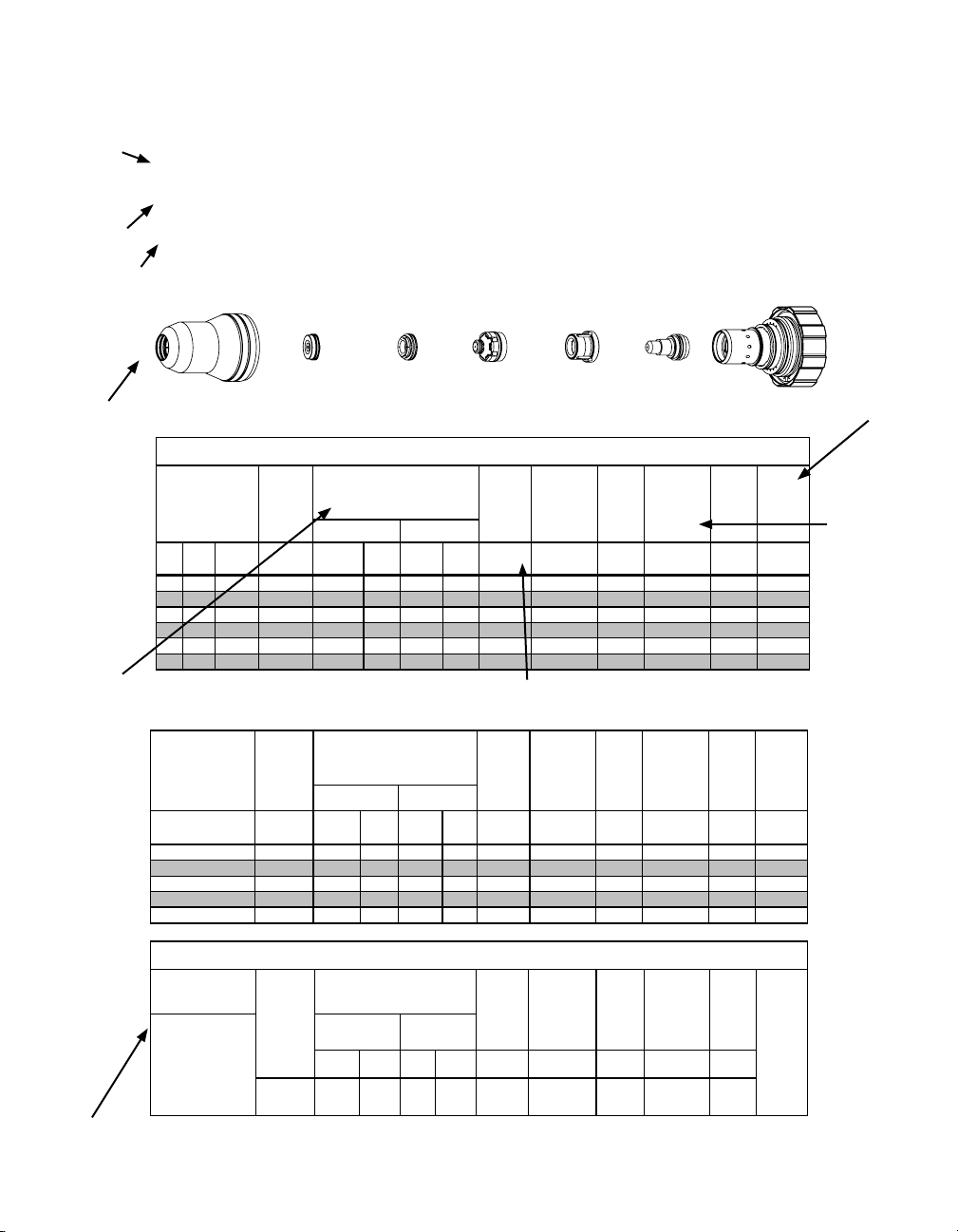
Cut charts
Cartridge
21-1020
Electrode
21-1068
Plasma
Gas Distributor
21-1040
Tip
21-1050
Shield Cap
21-1024
Shield Cup
21-1016
Art # A-06768
Shield
Gas Distributor
21-1082
Thermal Dynamics provides a cut parameters chart for every process and output current combination.
Material
Mild Steel
Current
Level
30A
O2 Plasma / O2 Shield
Process
Consumable Parts
Material
Thickness
(ga) (in) inch (PSI) Ball (PSI) Ball (PSI) Volts
20 0.036 60 22 120 21 120 128 0.050 130 0.120 0.2 0.058
16 0.060 60 22 120 21 120 143 0.050 60 0.120 0.3 0.070
14 0.075 60 22 120 21 120 145 0.070 45 0.120 0.3 0.072
12 0.105 60 22 120 21 120 148 0.110 40 0.150 0.3 0.074
10 0.135 80 22 120 21 120 154 0.130 30 0.150 0.3 0.085
3/16 0.188 80 22 120 21 120 154 0.120 25 0.150 0.4 0.075
Gas Control
Settings
Material
Thickness
(mm) (Bar) Ball (Bar) Ball (Bar) Volts
1 4.1 22 8.3 21 8.3 130 1.3 3050 3.0 0.2 1.5
2 4.1 22 8.3 21 8.3 145 1.9 1130 3.1 0.3 1.8
3 4.1 22 8.3 21 8.3 150 3.0 910 3.8 0.3 2.0
4 5.5 22 8.3 21 8.3 154 3.2 710 3.8 0.3 2.1
5 5.5 22 8.3 21 8.3 155 3.0 640 3.8 0.4 1.9
Pre Flow
Pressure
(Air)
Pre Flow
Pressure
(Air)
30A Mild Steel (O2/O2)
Cut Flow Rates /
Pressures
Plasma (O2) Shield (O2)
Cut Flow Rates /
Pressures
Plasma (O2)
Shield (O2)
Torch
Height
(in)
Travel
Speed
(ipm) (in) (sec) (in)
Arc
Voltage
Working
±0.005
Arc Voltage for
Torch Height Control
Travel
Torch
Arc
Voltage
Working
Height
(mm)
±0.1
Speed
(mm/
min)
Initial
Initial
Pierce
Delay
Pierce
Delay
@ Rec.
Speed
Width
@ Rec.
Speed
Piercing
Height
Piercing
Height
(mm) (sec) (mm)
Kerf Size
Kerf
Width
Kerf
Pierce
Data
Plasma Marking
Parameters
15A Arc Current
Burn-through
thicknesses
< 1/16” (0.063”) /
may
occur on
1.6 mm
Pre Flow
Pressure
(N2)
20psi
1.4 bar
Marking (with 30A Mild Steel Parts)
80 psi
5.5 bar
Arc
Voltage
145
Cut Flow Rates /
Pressures
Plasma
Pressure (N2)
Ball Press Ball Press Volts
40 psi
20
2.8 bar
Shield
Pressure N2)
70
page 3
Torch
Working
Height
In ±0.005 /
mm ± 0.1
0.1
2.5
Travel
Speed
ipm /
mm/min
300
7600
Initial
Piercing
Height
In ±0.005 /
mm ± 0.1
0.1
2.5
Pierce
Delay
(sec)
0
Marking
Quality
Degrades
as
Thickness
Decreases.
Page 4
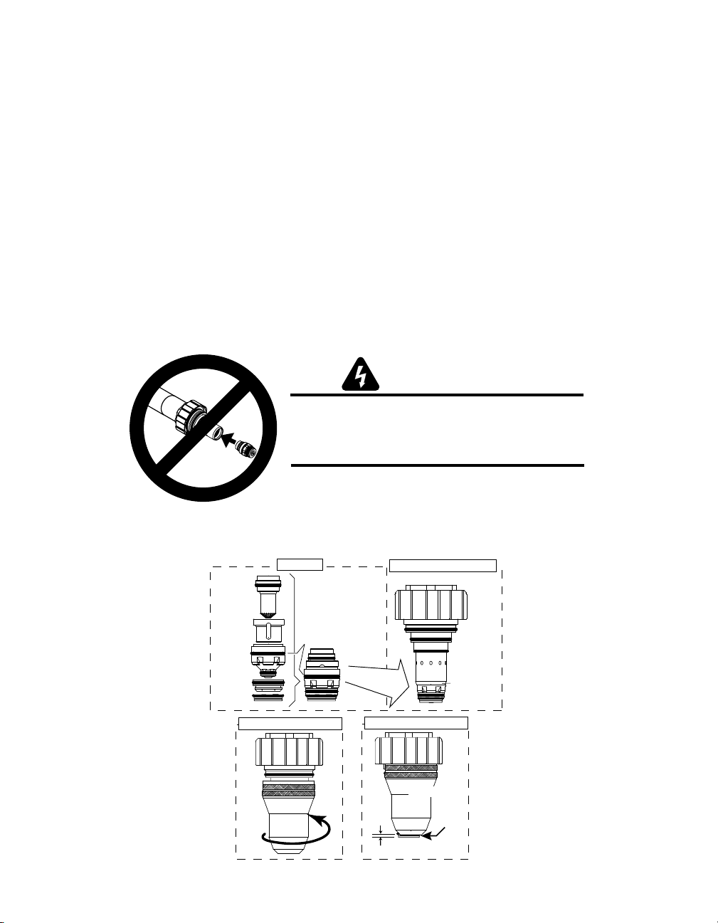
Consumable parts
Cartridge Covers
Upper O-Ring
on Torch Tip
Shield Cap Protrudes
0.063-0.083" (1.6 - 2.1 mm)
Electrode
Plasma Gas
Distributor
Tip
Shield Gas
Distributor
Shield Cap
Upper O-Ring
on Tip
1: Stack Parts
2: Press Cartridge onto Stacked Parts
4: Check Shield Cap Protrusion
Art # A-04716
No Gaps
Between Parts
3: Thread Shield Cup onto Cartridge
Shield Cap
Shield Cup
Parts selection
Consumable parts are specifically designed to perform in specific conditions. Using the
wrong consumable parts will result in short parts life and poor cut quality. Use the cut charts to
determine which consumable parts to use in any specific application.
Installing consumable parts
The XT torch is a precision instrument. Take care when installing consumable parts to keep the
parts clean and free from any contamination that might cause a gas or coolant leak inside the
consumable parts cartridge.
Assembly Sequence, 30-150 Amp Consumables
7.04 Torch Consumables Installation
Do not install consumables into the Cartridge
while the Cartridge is attached to the Torch Head.
Keep foreign materials out of the consumables and Cartridge.
Handle all parts carefully to avoid damage,
which may affect torch performance.
1. Install the consumables as follows:
WARNINGS
Art # A-03887
page 4
Page 5
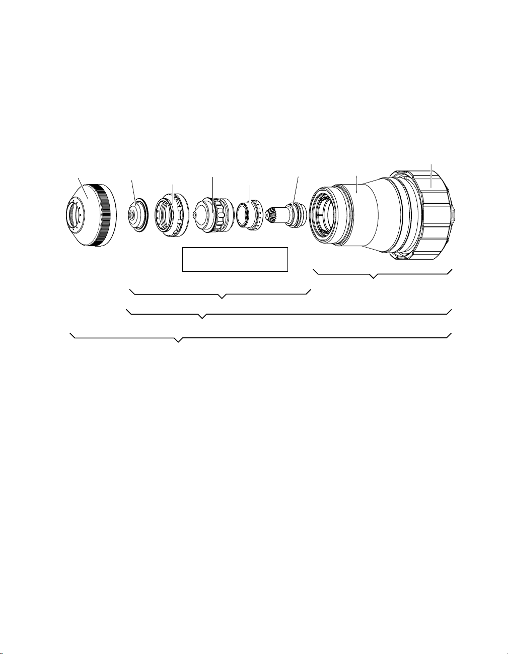
Tip
Electrode
Plasma Gas
Distributor
Shield Cap
Shield Gas
Distributor
Shield Retainer
Shield Cup
Assembly sequence:
Cartridge
1
2
3
4
Art # A-07424
Assembly Sequence, 200/300 Amp Consumables
To ensure proper assembly of the torch cartridge:
1. Place the cartridge assembly on a clean, flat surface
2. Assemble the consumable parts from electrode to shield cap.
3. Install the consumable parts in the cartridge
4. Install the shield retainer to complete the cartridge assebly.
page 5
Page 6
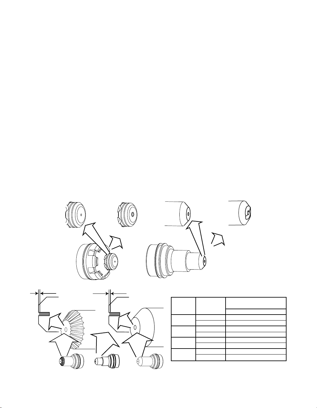
Consumable Parts Life
Tips and electrodes wear under normal usage. Tips and electrodes should be
changed before failure to avoid damaging the other consumable parts or the material to be
cut. Optimum life will vary according to specific cutting conditions. Keep a count of cuts
per set of tip and electrode in a given application to establish the most effective time to
change consumable parts sets. The pilot arc is more erosive to the tip and electrode than
the cutting arc is, so an application that demands more pilot and pierce sequences will erode
consumable parts faster than an application that uses longer cuts but fewer arc starts.
Tip – Tips wear as the arc erodes the tip orifice. When the tip is no longer round or has
become enlarged, it should be replaced. Tip life is best when cuts are made at optimum
speed. Cutting too fast or too slow causes the arc to bend and biases erosion, resulting
in an orifice that is oval shaped.
Electrodes – The electrode wears from the hafnium or tungsten insert at the end of the
electrode. The face of the insert is liquefied by the heat of the arc and droplets erode from
the insert as cutting progresses. Proper gas flow will support longer electrode life.
An electrode should be replaced when the electrode insert is pitted to a depth of 1/16 inch
(see chart below).
Replace the Gas Distributor if it is charred or cracked
Replace the Gas Disributor if the flange is damaged in any way
Replace the tip and/or electrode if they are worn
Torch
Electrodes
Good Tip
Worn Tip
Good Electrode
page 6
Worn Electrode
Art # A-04745_AB
Amperage Plasma Gas Recommended Wear Depth
for Replacement
30
50
70
100
Inch mm
O2 0.04 1
Air 0.04 2
O2 0.04 1
Air 0.08 2
O2 0.04 1
Air 0.08 2
O2 0.04 1
H35 0.08 2
Art # A-04704_AB
Page 7
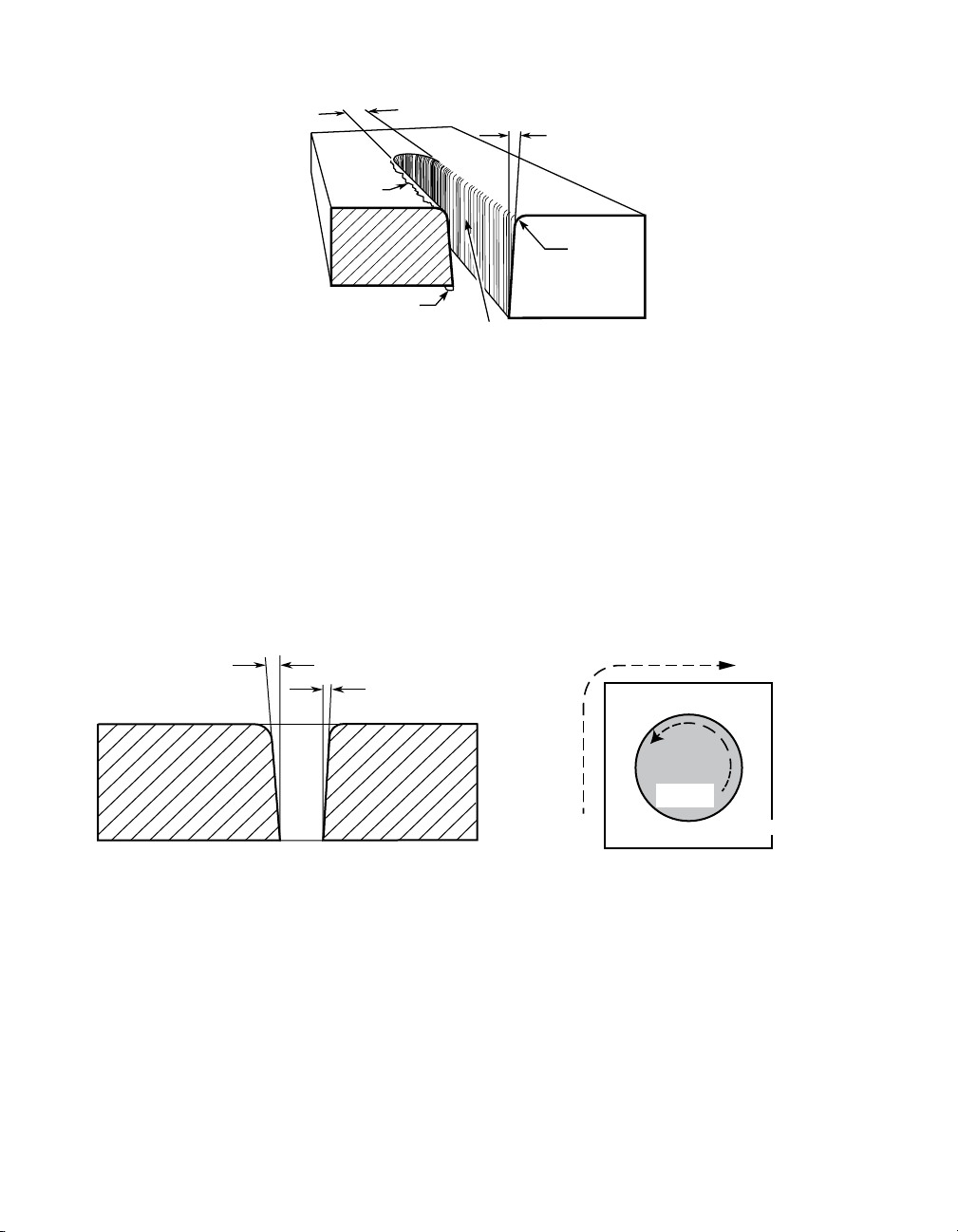
Cut characteristics
Kerf Width
Cut Surface
Bevel Angle
Top
Spatter
Top Edge
Rounding
Dross
Build-Up
Cut Surface
Drag Lines
Cut Surface – Cut surface is influenced by process and positioner precision more than by other
parameters. For smoothest cut face on different materials, use: mild steel – oxygen plasma
Direction of cut – The plasma has a clockwise swirl as it exits the torch tip. Considering the
direction of torch travel, the right side of the cut will always show less bevel and top edge
rounding than the left side. Program cuts so that the right side will be on the finished part and
the left side will be scrap.
A-00007
stainless < ¾’ – nitrogen / WMS
> ¾” – H35 / nitrogen
aluminum < ¾’ – nitrogen /WMS
> ¾” – H35 / nitrogen
Left Side
Cut Angle
Right Side
Cut Angle
A-00512
Clockwise
Scrap
Counter-
Clockwise
Scrap
Workpiece
Art # A-04182
Top edge rounding – Caused by the heat of the plasma arc at the top surface of the cut.
Proper torch height control can minimize or eliminate top edge rounding. Excessive top
edge rounding is often a sign that torch cutting height should be lower.
Top spatter – Top spatter is caused by fast cutting or by too high a torch height setting.
Reducing cut speed or lowering torch cutting height will reduce top spatter. Top spatter is
easy to remove.
Bottom dross – Molten metal may build up on the bottom of the plate. Faster cut speeds
reduce bottom dross as less material is melted. Bottom dross that is easy to remove is an
indication of slow cutting speed. Bottom dross that is difficult to remove or requires grinding
is an indication of too fast cut speed.
page 7
Page 8
Kerf – Kerf width is specified in the cut charts and can be calculated into cut programs.
The kerf width is related to tip orifice size and higher current cutting will produce a wider kerf.
Higher torch height will also result in a wider kerf.
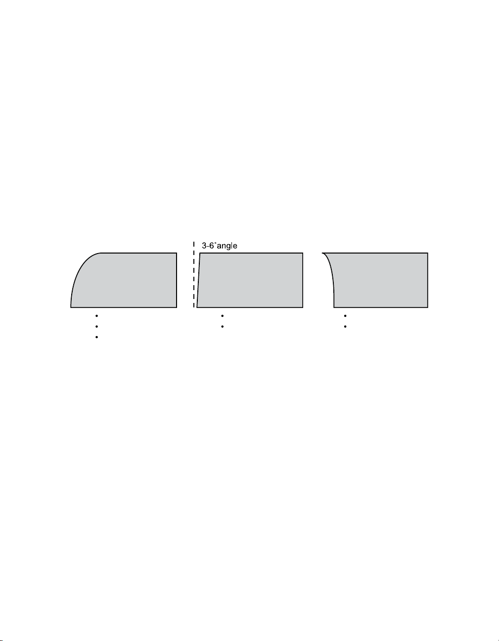
Bevel angle – Precision cut processes produce bevel angle in the 0-3° range. Conventional
plasma cutting will produce larger bevel angles. Proper torch height control will produce the
smallest bevel angle, as well as improved kerf width and minimal top edge rounding. A slower
cut speed can be used when cutting circles and corners to reduce bevel.
Effect of Height Control Settings – General Purpose Cut
Correct Voltage
High Voltage
Positive Bevel
Wide Kerf
Top Dross
Minimal Bevel
Normal Kerf
Low Voltage
Negative Bevel
Wide Kerf
Nitride contamination – Air plasma cutting will produce nitride contamination of the cut face
on carbon steel and stainless steel. Nitride contaminated surfaces will require grinding before
welding to eliminate weld porosity. The depth of the contamination will be close to the Heat
Affected Zone, between .005 and .010” in depth.
Nitride contamination can be eliminated by using a process other than air plasma;
oxygen plasma for carbon steel, H35 or nitrogen/WMS for non-ferrous materials.
Cut speed – Cut charts specify a cut speed that will produce high quality cut performance.
Any plasma system can cut at faster or slower speeds, but cut performance will be affected.
Cut speed should be reduced for corners and tight curves to reduce bevel and corner rounding.
Optimum cut speeds produce a trailing arc which will be visible in the slight arc lines
visible in the cut face. Arc lines are useful for evaluating cut speed on mild steel, but less so
for aluminum and stainless steel. Arc lines that trail at less than 15° indicate that cut speed is
in the optimum range when air or oxygen plasma processes are used. Optimum cut quality in
precision cutting processes will result in arc lines that are near vertical. A slow cut speed may
show arc lines that angle forward and a fast cut speed will show arc lines at a sharper angle
relative to the top of the plate.
page 8
Page 9

Aluminum
Cut Speed Too Fast
Cut drag lines are more than 15 degrees trailing the torch (torch movement right to left)
High speed bottom dross, easy to remove
Cut Speed Correct
Cut drag lines trail are visible, but cut surface is smooth. No dross
Cut Speed Too Slow
Cut drag lines are more pronounced and cut surface is rougher
page 9
Page 10

Stainless Steel (H35 plasma)
Cut Speed Too Fast
Gold heat discoloration swept in both directions
Cut drag lines more than 15 degrees trailing
High speed bottom dross, hard to remove
Cut Speed Correct
Smooth cut surface
No dross
Cut Speed Too Slow
Heat discoloration is concentrated in the bottom half of the cut
Hard bottom dross, hard to remove
page 10
Page 11

Mild Steel (O2 plasma)
Cut Speed Too Fast
Trailing cut drag lines
Light bottom dross, hard to remove, some top splatter
Cut Speed Correct
Cut drag lines near vertical
No dross
Cut Speed Too Slow
Cut drag lines lead the torch
Heavy bottom dross, easy to remove
page 11
Page 12

Mild Steel (Air plasma)
Cut Speed Too Fast
Cut drag lines curve and trail torch movement
High speed bottom dross, hard to remove
Cut Speed Correct
Cut drag lines near vertical
Minimal dross
Cut Speed Too Slow
Cut drag lines vertical or leading the torch head
Thicker bottom dross, easy to remove
page 12
Page 13

Piercing
Lead-out
Overcut
Corner
Pierce
Lead-in
Piercing causes the molten metal to form a puddle on top of the plate. On thicker plate,
pierce height is calculated to keep the torch away from the plate so that the molten metal does
not adhere to the consumable parts and shorten parts life. Hold pierce height as the cutting
table starts movement to allow the torch to clear the pierce puddle before moving to cut height.
Using the Inova height controller, this is done using the Set Pierce Time function on the edit
screen.
Lead-in and lead-out
Lead-in and lead-out should be calculated to allow the torch to move to cut height
before starting the final piece contour of the cut and to move away from the final piece before
beginning end of cut current ramp down.
Corners
The cutting arc normally trails the torch tip orifice. When the torch makes an abrupt
change in direction this trailing arc cannot change direction as quickly at the bottom of the cut
as at the top of the cut. This results in undercutting of sharp corners. 2 techniques can be used
to minimize this effect.
1. Use cut-outs – Overcut past the corner of the shape, then return and cross over the cut line to
achieve a square corner. Triangular or looped overcuts are commonly used.
2. Use the CNC corner slowdown function to hold torch height as it enters and leaves
the corner. As the speed decreases, the arc voltage will increase, driving the torch
down, so corner slowdown will lock out the height controller during the corner cut,
keeping the torch at the programmed height, regardless of arc voltage variations.
page 13
Page 14

Cutting Circles
Pierce
Lead-in
Overrun
at end
of cut
Circle cutting demands precise motion control and circle cut quality will vary as the circle
diameter approaches the thickness of the plate. In general, a circle that is equal in diameter
to the thickness of the plate being cut is the minimum circle diameter possible. Cut quality will
decrease markedly when the circle diameter is less than 1.5 times the thickness of the plate
being cut.
For maximum circle cut quality:
1. Slow down cut speed. Smaller circles may require a cut speed that is 60-50% of the
speed specified in system cut charts. A slower cut speed will eliminate trailing arc and allow the
arc to cut at closer to 0° of bevel.
2. Maintain constant cut height through the circle. This may require locking out the height
controller. As the cut speed slows, arc voltage increases and the height controller tends to drive
the torch down, changing cut bevel. Avoid torch height movement by locking out the height
controller during the circle cut.
3. Start the cut in the center of the circle and use a 90° lead-in to the circle. When the
positioner is in top running condition, a 90° lead-in will produce less distortion at the circle
initiation. A cutting table with backlash may produce a better cut when a radial lead-in is used.
4. End the cut by overburning the circle cut line rather than by using a lead-out. Time the
cut to end just as the arc completes the circle. A lead out or too much of an overburn will cause
the arc to cut more of the outside of the circle and cause a distortion at the point where the
circle cut is completed. Many CNC systems use and advanced off feature to ramp down cutting
current end of cut. Use of the CNC’s advanced off feature will improve circle cutting.
page 14
Page 15

N2/Water Mist Secondary
In this process, tap water is used instead of a shield gas. The water is vaporized as
it passes through the torch head and a portion of the molecules separate onto hydrogen and
oxygen. This vapor protects the cut surface from ambient air contamination and eliminates
nitriding in the cut surface.
Cutting with the N2/WMS process is economically efficient and produces genuine
precision cut quality over a broad range of non-ferrous applications.
Considerations:
• Water supply should be at least 55 psi.
• Hard water will leave mineral deposits, just as it does in sinks and faucets. A standard
water softening filter will prevent mineral deposits that can interfere with water flow in the
torch passages.
• Ohmic sensing to establish initial torch height is ineffective when water is present.
The ohmic clip should be removed from the torch for N2/WMS cutting. The ohmic sensing
system will sense the level of any water on the plate rather than the true position of the plate.
®™
Underwater Cutting
Cutting under water is used by some operators to capture smoke and reduce flash and noise.
Cutting under water is possible with Ultra-Cut and Auto-Cut systems.
Considerations:
• Cutting under water will reduce cut capacity and speed by up to 30%
• The cooling effect of water on the bottom of the plate will facilitate formation of dross
• Cutting aluminum under or over water releases hydrogen, which can explode
• Cutting with N2/WMS process is not recommended
• The water in the table will become contaminated with cut residue and can be a toxic waste
page 15
Page 16

Power Supply Status Codes
Art # A-04862
AC Indicator
Temp Indicator
Gas Indicator
DC Indicator
Status Indicator
Auto-Cut and Ultra-Cut systems display system status codes that are useful for
optimizing system performance and for troubleshooting. The status code is displayed on
the power supply front panel.
AC Power Indicator:
Indicates AC power is being supplied to the system when the
ON/OFF switch is in ON position. When switch is first set to
ON, the indicator will blink, indicating gas purge at power on.
TEMP Indicator:
Normally OFF. Indicator will come ON when the internal
temperature sensors detect temperatures above normal limits.
Let the unit cool before continuing operation.
GAS Indicator:
Normally ON. Indicates adequate gas pressure for
operation in the system.
Status Indicator:
DC Indicator:
Indicates the power supply is generating output DC voltage.
Show system status. The number of flashes indicates the
status.
Refer to the Status Code Section for details. On power supply start-up, the indicator
flashes to show the revision level of the operating software installed in the system.
page 16
Page 17

The Status Indicator flashes a 2 part code that indicates the status of the system.
When the Status Indicator is dark the system is ready to cut. It is normal for the Status Indicator
to flash when the GCM mode switch is placed in set mode. At system start up, the Status
Indicator flashes a 2 part code to indicate the CCM firmware version that is loaded into the
system. This code appears only once at start up. During normal operation the Status Indicator
may flash a code indicating an error or a condition that should be corrected. Some codes will
cause the system to cease operation to prevent damage to the hardware. Other codes will not
cause the system to cease operation, but will continue until the condition which caused the code
to initiate is changed.
Status codes appear in a 2 part sequence. The Status Indicator will flash a number of
times to indicate the first number in the code sequence, then pause for 1.2 seconds and flash
the second number of the code. After 4 seconds, the code sequence will repeat.
Example: The Status Indicator blinks 4 times, pauses, then blinks 3 times.
This code (4-3) indicates overheating coolant and will continue until the condition is corrected.
Status Indicator Codes
Fault Code Key
Error
Code
1-1 System not Enabled or
1-2 Pilot Ignition Failure Pilot did not start within 15 seconds.
1-3 Lost Pilot Pilot went out without shutoff signal; Preflow
1-4 Loss of Transfer Arc transfer (>50 ms.) then arc lost with START still
1-5 Off the Plate Function not currently enabled
1-6 Pilot Timed out w/o
1-7 Tip Saver Function not currently enabled.
1-8 Possible Shorted Torch Detected tip voltage too close to electrode voltage.
Error Remedy / Comments
Plasma Enable Off ; External E-Stop Activated or
Missing AC Input Phase
Transfer
CCM TB1-1&2 jumper missing; Missing AC Phase;
No power to GCM 2000 or 2010 Gas Control,
check GCM control cable connected, reset CP4
or CP5 circuit breaker in power supply, blown fuse
F19 in GCM.
Preflow pressure too high; Defective Arc Starter
pressure too high; cut current set too low for
consumables.
on. Standoff too high; Current set too low.
Must transfer from Pilot to Cutting Arc in 85 ms.
(SW8-1 OFF) or 3 sec. (SW8-1 ON). Standoff too
high or void in work under torch; cut current too low
for consumables; Preflow pressure too low.
Plasma flow/pressure too low; Plasma leak; cut
current too high; shorted torch body; consumable
parts worn out.
page 17
Page 18

Fault Code Key
Error
Code
Error Remedy / Comments
2-1 Missing Phase Blown fuse, Broken or loose connection on power cable
Inverter(s) not configured correctly for input voltage;
2-2 Wrong input voltage
Inverter or Pilot
2-3
Regulator Over
Temperature
Power Supply not
2-4
Ready
2-5 DC Output Low
Primary over current
2-6
fault
2-7 Unexpected current
Unexpected current
2-8
in pilot circuit
Unexpected current
2-9
in work lead
Poor power quality (brownouts, dropouts); Input power capacity
/ wiring too small causing voltage drop; broken or loose power
cable connections.
Failed fan; Ambient above 40 deg C. (104 F); Blocked airflow
Defective inverter
Output less than 60 VDC; Defective inverter, shorted output;
Shorted pilot regulator (chopper); CCM voltage sense (J6) wire
open or disconnected.
Over current detected in inverter primary circuit, remove power
to reset; defective inverter; voltage surge;
Current >20A in work or pilot leads before pilot ignition; Possible
shorted torch; Defective current sensor.
Current > 5A in pilot circuit; wrong or mismatched consumables;
Pilot lead shorted to negative in torch tube; Possible shorted
torch
Current > 5A in work lead; Short to chassis in RAS; Negative
lead short to ground.
page 18
Page 19

Error
Code
3-10
Error Remedy / Comments
Gas Control
Communication fault,
3-1
Cannot establish
Communication with
gas control.
Gas Control
Communication reply
fault, connection was
3-2
established but CCM
did receive a reply to
a process request.
3-3 Gas Pressure Low
Gas Control not
3-4
ready
Gas Control Protocol
3-5
Fault
Invalid Current
3-6
Control level from
GCM
Gas Control returns
3-7
wrong command
sequence
CCM and Gas
Control type
3-8
(Autocut-Ultracut)
mismatch
Gas Control
3-9
Communication reply
fault
Warning. -- Gas
Control firmware
needs update
Fault Code Key
If GCM 1000: Control cable not connected or Basic ID signal
open. GCM 2010 & 2000: Dirt on fiber ends or in connectors,
blow out with clean dry air; fiber not locked into connector;
sharp bends in fiber; fiber defective; Gas Control PCB defective,
replace. CCM defective, replace.
Gas Control did not reply to signal from CCM in allowed time.
Dirt on fiber ends or in connectors, blow out with clean dry
air; fiber not locked into connector; sharp bends in fiber; fiber
defective. If problem persists Gas Control PCB likely defective,
replace board.
If GCM 1000, Plasma < 15 PSI; faulty or disconnected pressure
SW. If GCM2010_AG, GCM2000_AC or later or Gas Control
has been updated with 19X2219_AG or later PCB: Plasma or
Shield input out of range 105-135. If GCM2010_AG,
GCM2000_AC or later or Gas Control has been updated with
19X2219_AG or later PCB: Plasma or Shield input out of range
105-135 PSI; Unplugged or Faulty pressure sensor.
Purging; not in RUN mode; Gas Control faulty, replace PCB.
Application error or firmware compatibility fault
GCM sent output current level outside the range of the power
supply, Check firmware compatibility
Check firmware compatibility
Install correct CCM or Gas Control for system
Reply not compatible with request; Check firmware compatibility
System will function but control may not be optimized for best
performance / consumable life
page 19
Page 20

Fault Code Key
Er r o r
Code
Error Remedy / Comments
4-1 Coolant Level low fault Check coolant level, add as needed.
Low coolant flow
after power on purge.
Not cutting:
< 0.7 gal/min for 15 sec;
4-2
Cutting: flow between
0.35 to 0.7 gal/min for 3
sec. or immediately if
< 0.35gal/min;
Coolant overheated
4-3
(>70 deg. C, 158 deg F)
Coolant System not
ready. During power on
4-4
purge / priming, flow did
not reach 0.35 gal/min
for at least 5 seconds
Low Coolant Level
4-5
- Warning
Suction leak introducing air into coolant, suspect rear panel
filter seal; clogged filter; defective pump.
Coolant fan failed; radiator fins clogged with dirt; Ambient
temperature > 40 deg C.
If new installation recycle power to restart
pump, may take a few times to fill hoses;
Damaged torch coolant tube; Suction leak introducing air
into coolant, suspect rear panel filter seal; clogged filter;
defective pump.
While cutting detected low coolant level, does not stop cut.
Add coolant as required.
page 20
Page 21

Error
Code
Error Remedy / Comments
CANBUS Failure to
5-1
Acknowledge fault.
CANBUS Off due to
5-2
excessive data errors;
CANBUS data error
warning. Errors
5-3
increasing, will soon
fault.
5-4 CCM Message not sent
CCM Analog
6-1
Voltage Error
CCM ADC
6-2
or DAC error
Coolant Flow too High
6-3
error, flow > 2.7 gal/min
CCM Data Memory
6-4
error
Fault Code Key
If GCM 1000, Basic ID signal missing; Other gas controls,
Fiber disconnected or broken, Transceiver (what fiber plugs
into) fault, replace Gas control PCB or CCM
Dirt on fiber ends or in connectors, blow out with clean dry
air; fiber not locked into connector; sharp bends in fiber; fiber
defective;
Dirt on fiber ends or in connectors, blow out with clean dry
air; fiber not locked into connector; sharp bends in fiber; fiber
defective;
Dirt on fiber ends or in connectors, blow out with clean dry
air; fiber not locked into connector; sharp bends in fiber; fiber
defective; CANBUS hardware error (CCM or Gas Control
PCB)
Replace CCM
Replace CCM
Torch coolant tube broken or missing; CCM fault, replace
CCM
Replace CCM
page 21
Page 22

Scheduled Maintenance
O-Rings
Art # A-04066
Cat. No. 8-0539
Cat. No. 8-3487
Cat. No. 8-0530
Torch Head
Cat. No. 9-9041
O-Ring, Cat. No. 8-0544
Inner O-Ring (Cat. No. 8-0545)
Location (Under Locking Ring)
O-Ring, Cat. No. 8-0540
Art # A-04071
Snap Ring
Cartridge Assembly
Lubricate Torch Cartridge O-Rings
Lubricate all three O-Rings on the Cartridge Assembly and all three O-Rings on the Torch
Head periodically with O-Ring Lubricant supplied. Remove the snap ring on the cartridge
assembly and slide the locking ring downward for access to the O-Ring under the locking ring.
Use only Thermal Dynamics No. 9-4893 O-Ring Oxygen Compatable Lubricant (Christo Lube MCG-129)
with this torch part. Use of other lubricants may cause irreparable damage to the torch.
An O-ring replacement kit with both torch and cartridge rings is available, catalog number 9-9488.
Coolant
Torch coolant becomes conductive with use and eventually will cause a shorted torch
condition. Torch coolant should be replaced every six months. Also remove and clean the
external coolant filter and the smaller filter located near the flow sensor.
Torch coolant is available pre-mixed or as concentrate.
Catalog Number Description
7-3580 Extra-Cool™ 25/75 10°F / -12°C
7-3581 Ultra-Cool™ 50/50 -27°F / -33°C
7-3582 Extreme-Cool™
7-3523 De-l Water™ 32°F / 0°C
CAUTION
Propylene Glycol/
Deionized Water Mix
Concentrate to be mixed
with De-l™ Water
Freeze Protection
-65°F / -51°C
page 22
Page 23

Periodic Maintenance
No
Yes
Yes
Are Parts New
or Used?
Are Parts fully
assembled into
the Torch?
Unsure?
Disassembly fully
and re-assemble
the Torch Properly.
See Installation Manual.
Replace Torch Head
Is the Torch Damaged?
Replace Consumable
Cartridge and Shield Cup.
Torch still leaks?
Remove and Lubricate
all O-rings on Torch Head,
Consumables Cartridge,
and Consumables.
Re-assemble Torch.
Still leaks?
The parts probably are worn out.
See chart for approximate life expectancy.
The torch may be damaged. See page
to determine if head damage has occurred.
Order Coolant
Tube Replacement Kit
Leaking from
Coolant Supply or
Coolant Return?
Yes
Yes
Yes
No
Return
Supply
Used
Order Coolant
Check Valve
Kit 9-4846
New
Torch leaks
Are Torch
Consumable Parts
Installed?
Daily
Check coolant level; add coolant as needed.
Check gas hose connections and pressures.
Check cooling fan; clean as needed.
Monthly
Check cooling fan and radiator; clean as needed.
Check gas hoses for cracks, leaks, or abrasions.
Replace as needed.
Check all electrical connections for cracks or abrasion.
Replace as needed.
Clean water filter (if using H20 Mist).
Six Months
Replace coolant filter.
Clean coolant tank.
Vacuum out any dust buildup inside power supply.
Power Supply Maintenance Schedule
Troubleshooting Torch Coolant Leaks
page 23
Page 24

Technical Service Contact Numbers
Thermal Dynamics Technical Service is available for telephone or e-mail
support. Technicians are available to assist with installation, application and
repair issues.
Technical Service Toll Free – 1-800-PLASMA2 (752-7622)
Automation Technical Service – 1-888-832-3477
Automation Customer Care – 1-866-279-2628
General Customer Care – 1-800-PLASMA1 (752-7621)
E-mail - tdctech@thermadyne.com
www.thermal-dynamics.com
U.S. Customer Care: ARCAIR
FIREPOWER® .................800-858-4232 / FAX 800-535-0557 TDC AUTOMATION ..................866-279-2628 / FAX 800-221-4401
TURBOTORCH
®
/ STOODY® / THERMAL ARC® / THERMAL DYNAMICS® / TWECO® / VICTOR
®
............. 800-238-0282 / FAX 800-535-0557 VICTOR MEDICAL .................... 800-382-8187 / FAX 800-535-0557
®
................... 800-426-1888 / FAX 800-535-0557
VICTOR SPECIALTY PRODUCTS ...................800-569-0547 / FAX 800-535-0557
Canada Customer Care: 905-827-4515 / FAX 800-588-1714 • International Customer Care: 905-827-9777 / FAX 905-827-9797
CIGWELD Customer Care: 1300-654-674 / FAX 613+ 9474-7391 • www.thermadyne.com
A Global Cutting & Welding Market Leader
W O R LD H EA DQ UA R T ER S: 1 60 52 S wi ng l ey Ri dg e Ro ad , S u i te 3 00 • S t. Lo ui s, M is so ur i 63 01 7 U .S .A .
THE AMERICAS EUROPE ASIA/PACIFIC
Denton, TX USA
U.S. Customer Care
Ph: (1) 800-426-1888
Fax: (1) 800-535-0557
Miami, FL USA
Sales Office, Latin America
Ph: (1) 954-727-8371
Fax: (1) 954-727-8376
Form No. 63-2823 (5/13/08) © Thermadyne Industries, Inc., 2008 www.thermadyne.com Printed in U.S.A.
Oakville, Ontario, Canada
Canada Customer Care
Ph: (1) 905-827-4515
Fax: (1) 800-588-1714
International Customer Care
Ph: (1) 905-827-9777
Fax: (1) 905-827-9797
Chorley, United Kingdom
Customer Care
Ph: (44) 1257-261755
Fax: (44) 1257-224800
Milan, Italy
Customer Care
Ph: (39) 0236546801
Fax: (39) 0236546840
Cikarang, Indonesia
Customer Care
Ph: 62 21+ 8983-0011 / 0012
Fax: 62 21+ 893-6067
Osaka, Japan
Sales Office
Ph: 816-4809-8411
Fax: 816-4809-8412
Melbourne, Australia
Australia Customer Care:
Ph: 1300-654-674
Fax: 613+ 9474-7391
International:
Ph: 613+ 9474-7508
Fax: 613+ 9474-7488
Rawang, Malaysia
Customer Care
Ph: 603+ 6092-2988
Fax: 603+ 6092-1085
Shanghai, China
Sales Office
Ph: 86 21+ 6280-1273
Fax: 86 21+ 3226-0955
Singapore
Sales Office
Ph: 65+ 6832-8066
Fax: 65+ 6763-5812
™
 Loading...