

Page 1
101
SL100SV
™
CUTMASTER
AUTOMATED
PLASMA CUTTING SYSTEM
PLASMA CUTTING
MACHINE TORCH
Art # A-04611
Operating Manual
Rev. AD.01 Date: April 2, 2007 Manual # 0-4642
Operating Features:
Page 2

WE APPRECIATE YOUR BUSINESS!
Congratulations on your new Thermal Dynamics product. We are
proud to have you as our customer and will strive to provide you
with the best service and reliability in the industry. This product is
backed by our extensive warranty and world-wide service network.
To locate your nearest distributor or service agency call 1-800426-1888, or visit us on the web at www.thermal-dynamics.com.
This Operating Manual has been designed to instruct you on the
correct use and operation of your Thermal Dynamics product.
Your satisfaction with this product and its safe operation is our
ultimate concern. Therefore please take the time to read the entire
manual, especially the Safety Precautions. They will help you to
avoid potential hazards that may exist when working with this
product.
YOU ARE IN GOOD COMPANY!
The Brand of Choice for Contractors and Fabricators Worldwide.
Thermal Dynamics is a Global Brand of manual and automation
Plasma Cutting Products for Thermadyne Industries Inc.
We distinguish ourselves from our competition through marketleading, dependable products that have stood the test of time.
We pride ourselves on technical innovation, competitive prices,
excellent delivery, superior customer service and technical
support, together with excellence in sales and marketing expertise.
Above all, we are committed to developing technologically
advanced products to achieve a safer working environment within
the welding industry.
Page 3

W ARNINGS
Read and understand this entire Manual and your employer’s safety practices before installing, operating, or servicing the equipment.
While the information contained in this Manual represents the Manufacturer's best judgement, the
Manufacturer assumes no liability for its use.
Automated Plasma Cutting System
Automated CutMaster™ 101 Power Supply
SL100 / SL100SV Machine Torch
Operating Manual Number 0-4642
Covered under U.S. Patents
Published by:
Thermal Dynamics Corporation
82 Benning Street
West Lebanon, New Hampshire, USA 03784
(603) 298-5711
www.thermal-dynamics.com
© Copyright 2004, 2005, 2006, 2007 by
Thermal Dynamics Corporation
All rights reserved.
Reproduction of this work, in whole or in part, without written permission of the publisher is prohibited.
The publisher does not assume and hereby disclaims any liability to any party for any
loss or damage caused by any error or omission in this Manual, whether such error
results from negligence, accident, or any other cause.
Printed in the United States of America
Publication Date: April 2, 2007
Record the following information for Warranty purposes:
Where Purchased:____________________________________
Purchase Date:_______________________________________
Power Supply Serial #:________________________________
Torch Serial #:________________________________________
Page 4

Page 5

TABLE OF CONTENTS
SECTION 1:
GENERAL INFORMATION ................................................................................................ 1-1
1.01 Notes, Cautions and Warnings ...................................................................... 1-1
1.02 Important Safety Precautions ....................................................................... 1-1
1.03 Publications .................................................................................................. 1-3
1.04 Note, Attention et Avertissement .................................................................. 1-3
1.05 Precautions De Securite Importantes ........................................................... 1-4
1.06 Documents De Reference ............................................................................. 1-5
1.07 Declaration of Conformity ............................................................................. 1-7
1.08 Statement of Warranty .................................................................................. 1-8
SECTION 2: SPECIFICATIONS ................................................................................................ 2-1
2.01 Scope of Manual .......................................................................................... 2-1
2.02 Power Supply Specifications ......................................................................... 2-1
2.03 Input Wiring Specifications ........................................................................... 2-2
2.04 Power Supply Features ................................................................................. 2-3
2.05 Power Supply Options and Accessories ....................................................... 2-4
2.06 Torch Specifications ..................................................................................... 2-5
2.07 Torch Options and Accessories .................................................................... 2-6
2.08 Introduction to Plasma .................................................................................. 2-7
SECTION 3: INSTALLATION ..................................................................................................... 3-1
3.01 Unpacking .................................................................................................... 3-1
3.02 Lifting Options .............................................................................................. 3-1
3.03 Primary Input Power Connections ................................................................. 3-2
3.04 Gas Connections .......................................................................................... 3-4
3.05 Torch Connections ........................................................................................ 3-7
3.06 Torch Installation .......................................................................................... 3-9
3.07 Torch Parts Selection................................................................................... 3-10
3.08 Power Supply Connection to SC-11 Standoff Control ................................... 3-11
3.09 Power Supply Connection to Alternate Standoff Control ............................... 3-12
3.10 Automation Interface PC Board Set-up ........................................................ 3-14
3.11 Optional Remote Current Control Harness Installation .................................. 3-15
SECTION 4: OPERATION ......................................................................................................... 4-1
4.01 Product Features .......................................................................................... 4-1
4.02 Preparations For Operating ........................................................................... 4-2
4.03 Selection, Inspection and Replacement of Consumable Torch Parts ............. 4-6
4.04 Cut Quality ................................................................................................... 4-8
4.05 General Cutting Information .......................................................................... 4-9
4.06 Torch Operation ........................................................................................... 4-10
4.07 Cutting Parameters ...................................................................................... 4-12
4.08 Cutting Specifications ..................................................................................4-13
4.09 Cutting Speed Chart: Mild Steel, SL100 Torch with Exposed Tip .................. 4-14
4.10 Cutting Speed Charts: Stainless Steel, SL100 Torch with Exposed Tip ........ 4-15
4.11 Cutting Speed Charts: Aluminum, SL100 Torch with Exposed Tip ................4-16
4.12 Cutting Speed Charts: Mild Steel, SL100 Torch with Shielded Tip ................ 4-17
4.13 Cutting Speed Charts: Stainless Steel, SL100 Torch with Shielded Tip ........ 4-18
4.14 Cutting Speed Charts: Aluminum, SL100 Torch with Shielded Tip ................ 4-19
4.15 Operator's Custom Cutting Speed Charts .................................................... 4-20
Page 6

TABLE OF CONTENTS (continued)
SECTION 5:
SERVICE .......................................................................................................................... 5-1
5.01 General Maintenance .................................................................................... 5-1
5.02 Common Faults ............................................................................................ 5-5
5.03 Basic Troubleshooting ................................................................................... 5-6
5.04 Advanced Troubleshooting Guide - General Information ............................... 5-11
5.05 Main Input and Internal Power Problems ...................................................... 5-13
5.06 Pilot Arc Problems .......................................................................................5-19
5.07 Main Arc Problems ...................................................................................... 5-24
5.08 Test Procedures........................................................................................... 5-25
5.09 Power Supply Major External Parts Replacement ........................................5-31
5.10 Front Panel Parts Replacement.................................................................... 5-33
5.11 Left Side Internal Parts Replacement .......................................................... 5-35
5.12 Right Side Internal Parts Replacement ........................................................ 5-42
SECTION 6:
PARTS LISTS ................................................................................................................... 6-1
6.01 Introduction ................................................................................................... 6-1
6.02 Ordering Information ..................................................................................... 6-1
6.03 Complete Power Supply Replacement .......................................................... 6-1
6.04 Power Supply Basic Replacement Parts ....................................................... 6-2
6.05 Power Supply Options and Accessories ....................................................... 6-2
6.06 Power Supply Major External Replacement Parts ......................................... 6-3
6.07 Power Supply Front Panel Replacement Parts ............................................. 6-4
6.08 Rear Panel Replacement Parts .................................................................... 6-5
6.09 Power Supply Left Side Internal Replacement Parts .................................... 6-6
6.10 Right Side Internal Replacement Parts ........................................................ 6-8
6.11 Torch Replacement Parts .............................................................................6-10
6.12 Torch Replacement Parts .............................................................................6-12
6.13 Torch Consumables ..................................................................................... 6-14
6.14 Torch Spare Parts Kits .................................................................................6-14
6.15 Complete Torch Assembly Replacement ...................................................... 6-16
6.16 Torch Options & Accessories ...................................................................... 6-16
PATENT INFORMATION ...........................................................................................................6-17
APPENDIX 1: SEQUENCE OF OPERATION
(BLOCK DIAGRAM) .......................................................................................................... A-1
APPENDIX 2: DATA TAG INFORMATION ................................................................................ A-2
APPENDIX 3: MAINTENANCE SCHEDULE ............................................................................. A-3
APPENDIX 4: TORCH PIN - OUT DIAGRAMS.......................................................................... A-4
APPENDIX 5: TORCH CONNECTION DIAGRAMS .................................................................. A-5
APPENDIX 6: CONTROL CABLE PIN - OUT DIAGRAM .......................................................... A-6
APPENDIX 7: INTERFACE PCB SWITCH SETTINGS (MOST COMMON SETTINGS) ............ A-7
Page 7

TABLE OF CONTENTS (continued)
APPENDIX 8: INTERFACE PCB SWITCH SETTINGS (Division Factors 16-24) ....................... A-8
APPENDIX 9: INTERFACE PCB SWITCH SETTINGS (Division Factors 24-30) ....................... A-9
APPENDIX 10: INTERFACE PCB SWITCH SETTINGS (Division Factors 30-33) ................... A-10
APPENDIX 11: INTERFACE PCB SWITCH SETTINGS (Division Factors 33-36) ................... A-11
APPENDIX 12: INTERFACE PCB SWITCH SETTINGS (Division Factors 36-43) ................... A-12
APPENDIX 13: INTERFACE PCB SWITCH SETTINGS (Division Factors 43-50) ................... A-13
APPENDIX 14: AUTOMATION INTERFACE PC BOARD WIRING LAYOUT ............................ A-14
APPENDIX 15: AUTOMATION INTERFACE PC BOARD LAYOUT and TEST POINTS ........... A-15
APPENDIX 16: AUTOMATION INTERFACE PC BOARD WIRING CONNECTIONS TO
OEM CNC HARNESS .................................................................................................... A-16
APPENDIX 17: AUTOMATION INTERFACE PC BOARD WIRING CONNECTIONS TO
ALTERNATE CNC HARNESS .......................................................................................... A-17
APPENDIX 18: MAIN PC BOARD LAYOUT ............................................................................ A-18
APPENDIX 19: MAIN PC BOARD WIRING LAYOUT (208 /230-Volt POWER SUPPLIES) ...... A-20
APPENDIX 20: MAIN PC BOARD WIRING LAYOUT (400-Volt, 415-Volt, 460-Volt,
600-Volt POWER SUPPLIES) ......................................................................................... A-21
APPENDIX 21: LOGIC BOARD LAYOUT ................................................................................ A-22
APPENDIX 22: POT / LED BOARD LAYOUT .......................................................................... A-23
APPENDIX 23: OUTPUT BOARD WIRING DIAGRAM ............................................................ A-24
APPENDIX 24: OUTPUT DIODE BOARD LAYOUT ................................................................ A-25
APPENDIX 25: PILOT BOARD LAYOUT ................................................................................. A-26
APPENDIX 26: 28VAC CIRCUIT DIAGRAM ........................................................................... A-27
APPENDIX 27: INPUT DIODE LAYOUT.................................................................................. A-28
APPENDIX 28: 208/230V SYSTEM SCHEMATIC ................................................................... A-30
APPENDIX 29: 208/230V SYSTEM SCHEMATIC ................................................................... A-32
APPENDIX 30: 400 / 415V / 460V SYSTEM SCHEMATIC ..................................................... A-34
Page 8

TABLE OF CONTENTS (continued)
APPENDIX 31: 400 / 415V / 460V SYSTEM SCHEMATIC ..................................................... A-36
APPENDIX 32: 600V SYSTEM SCHEMATIC ........................................................................... A-38
APPENDIX 33: 600V SYSTEM SCHEMATIC ........................................................................... A-40
APPENDIX 34: Publication History .......................................................................................... A-42
Global Customer Service Contact Information ..................................................... Inside Rear Cover
Page 9
SECTION 1:
GENERAL INFORMATION
1.01 Notes, Cautions and Warnings
Throughout this manual, notes, cautions, and warnings
are used to highlight important information. These highlights are categorized as follows:
NOTE
An operation, procedure, or background information which requires additional emphasis or is helpful in efficient operation of the system.
CAUTION
A procedure which, if not properly followed, may
cause damage to the equipment.
WARNING
A procedure which, if not properly followed, may
cause injury to the operator or others in the operating area.
1.02 Important Safety Precautions
WARNINGS
OPERATION AND MAINTENANCE OF
PLASMA ARC EQUIPMENT CAN BE DANGEROUS AND HAZARDOUS TO YOUR
HEALTH.
Plasma arc cutting produces intense electric and
magnetic emissions that may interfere with the
proper function of cardiac pacemakers, hearing
aids, or other electronic health equipment. Persons who work near plasma arc cutting applications should consult their medical health professional and the manufacturer of the health
equipment to determine whether a hazard exists.
GASES AND FUMES
Gases and fumes produced during the plasma cutting process
can be dangerous and hazardous to your health.
• Keep all fumes and gases from the breathing area. Keep
your head out of the welding fume plume.
• Use an air-supplied respirator if ventilation is not adequate to remove all fumes and gases.
• The kinds of fumes and gases from the plasma arc depend on the kind of metal being used, coatings on the
metal, and the different processes. You must be very
careful when cutting or welding any metals which may
contain one or more of the following:
Antimony Chromium M ercury
Arsenic Cobalt Nickel
Barium Copper Selenium
Beryllium Lead Silver
Cadmium Manganese Vanadium
• Always read the Material Safety Data Sheets
(MSDS) that should be supplied with the material
you are using. These MSDSs will give you the information regarding the kind and amount of fumes
and gases that may be dangerous to your health.
• For information on how to test for fumes and gases
in your workplace, refer to item 1 in Subsection 1.03,
Publications in this manual.
• Use special equipment, such as water or down draft
cutting tables, to capture fumes and gases.
• Do not use the plasma torch in an area where combustible or explosive gases or materials are located.
• Phosgene, a toxic gas, is generated from the vapors
of chlorinated solvents and cleansers. Remove all
sources of these vapors.
• This product, when used for welding or cutting,
produces fumes or gases which contain chemicals
known to the State of California to cause birth defects and, in some cases, cancer. (California Health
& Safety Code Sec. 25249.5 et seq.)
To prevent possible injury, read, understand and
follow all warnings, safety precautions and instructions before using the equipment. Call 1-603298-5711 or your local distributor if you have any
questions.
Manual 0-4642 1-1 GENERAL INFORMATION
Page 10
ELECTRIC SHOCK
NOISE
Electric Shock can injure or kill. The plasma arc process uses
and produces high voltage electrical energy. This electric energy can cause severe or fatal shock to the operator or others
in the workplace.
• Never touch any parts that are electrically “live” or “hot.”
• Wear dry gloves and clothing. Insulate yourself from
the work piece or other parts of the welding circuit.
• Repair or replace all worn or damaged parts.
• Extra care must be taken when the workplace is moist or
damp.
• Install and maintain equipment according to NEC code,
refer to item 9 in Subsection 1.03, Publications.
• Disconnect power source before performing any service
or repairs.
• Read and follow all the instructions in the Operating
Manual.
FIRE AND EXPLOSION
Fire and explosion can be caused by hot slag, sparks, or the
plasma arc.
• Be sure there is no combustible or flammable material in
the workplace. Any material that cannot be removed
must be protected.
• Ventilate all flammable or explosive vapors from the workplace.
• Do not cut or weld on containers that may have held
combustibles.
• Provide a fire watch when working in an area where fire
hazards may exist.
• Hydrogen gas may be formed and trapped under aluminum workpieces when they are cut underwater or while
using a water table. DO NOT cut aluminum alloys underwater or on a water table unless the hydrogen gas
can be eliminated or dissipated. Trapped hydrogen gas
that is ignited will cause an explosion.
Noise can cause permanent hearing loss. Plasma arc processes
can cause noise levels to exceed safe limits. You must protect
your ears from loud noise to prevent permanent loss of hearing.
• To protect your hearing from loud noise, wear protective
ear plugs and/or ear muffs. Protect others in the workplace.
• Noise levels should be measured to be sure the decibels
(sound) do not exceed safe levels.
• For information on how to test for noise, see item 1 in
Subsection 1.03, Publications, in this manual.
PLASMA ARC RAYS
Plasma Arc Rays can injure your eyes and burn your skin. The
plasma arc process produces very bright ultra violet and infra
red light. These arc rays will damage your eyes and burn your
skin if you are not properly protected.
• To protect your eyes, always wear a welding helmet or
shield. Also always wear safety glasses with side shields,
goggles or other protective eye wear.
• Wear welding gloves and suitable clothing to protect
your skin from the arc rays and sparks.
• Keep helmet and safety glasses in good condition. Replace lenses when cracked, chipped or dirty.
• Protect others in the work area from the arc rays. Use
protective booths, screens or shields.
• Use the shade of lens as suggested in the following per
ANSI/ASC Z49.1:
Minimum Protective Suggested
Arc Current Shade No. Shade No.
Less Than 300* 8 9
300 - 400* 9 12
400 - 800* 10 14
* These values apply where the actual arc is
clearly seen. Experience has shown that lighter
filters may be used when the arc is hidden by the
workpiece.
GENERAL INFORMATION 1-2 Manual 0-4642
Page 11
1.03 Publications
Refer to the following standards or their latest revisions for
more information:
1. OSHA, SAFETY AND HEALTH STANDARDS, 29CFR
1910, obtainable from the Superintendent of Documents,
U.S. Government Printing Office, Washington, D.C. 20402
2. ANSI Standard Z49.1, SAFETY IN WELDING AND CUTTING, obtainable from the American Welding Society, 550
N.W. LeJeune Rd, Miami, FL 33126
3. NIOSH, SAFETY AND HEALTH IN ARC WELDING AND
GAS WELDING AND CUTTING, obtainable from the Superintendent of Documents, U.S. Government Printing Office, Washington, D.C. 20402
4. ANSI Standard Z87.1, SAFE PRACTICES FOR OCCUPATION AND EDUCATIONAL EYE AND FACE PROTECTION, obtainable from American National Standards Institute, 1430 Broadway, New York, NY 10018
5. ANSI Standard Z41.1, STANDARD FOR MEN’S SAFETYTOE FOOTWEAR, obtainable from the American National
Standards Institute, 1430 Broadway, New York, NY 10018
14. American Welding Society Standard AWSF4.1, RECOMMENDED SAFE PRACTICES FOR THE PREPARATION
FOR WELDING AND CUTTING OF CONTAINERS AND
PIPING THAT HAVE HELD HAZARDOUS SUBSTANCES,
obtainable from the American Welding Society, 550 N.W.
LeJeune Rd, Miami, FL 33126
15. ANSI Standard Z88.2, PRACTICE FOR RESPIRATORY
PROTECTION, obtainable from American National Standards Institute, 1430 Broadway, New York, NY 10018
1.04 Note, Attention et
Avertissement
Dans ce manuel, les mots “note,” “attention,” et “avertissement”
sont utilisés pour mettre en relief des informations à caractère
important. Ces mises en relief sont classifiées comme suit :
NOTE
Toute opération, procédure ou renseignement
général sur lequel il importe d’insister davantage
ou qui contribue à l’efficacité de fonctionnement
du système.
6. ANSI Standard Z49.2, FIRE PREVENTION IN THE USE OF
CUTTING AND WELDING PROCESSES, obtainable from
American National Standards Institute, 1430 Broadway, New
York, NY 10018
7. AWS Standard A6.0, WELDING AND CUTTING CONTAINERS WHICH HAVE HELD COMBUSTIBLES, obtainable from American Welding Society, 550 N.W.
LeJeune Rd, Miami, FL 33126
8. NFPA Standard 51, OXYGEN-FUEL GAS SYSTEMS
FOR WELDING, CUTTING AND ALLIED PROCESSES, obtainable from the National Fire Protection
Association, Batterymarch Park, Quincy, MA 02269
9. NFPA Standard 70, NATIONAL ELECTRICAL CODE,
obtainable from the National Fire Protection Association, Batterymarch Park, Quincy, MA 02269
10. NFPA Standard 51B, CUTTING AND WELDING PROCESSES, obtainable from the National Fire Protection Association, Batterymarch Park, Quincy, MA 02269
11. CGA Pamphlet P-1, SAFE HANDLING OF COMPRESSED
GASES IN CYLINDERS, obtainable from the Compressed
Gas Association, 1235 Jefferson Davis Highway, Suite 501,
Arlington, VA 22202
ATTENTION
Toute procédure pouvant résulter
l’endommagement du matériel en cas de nonrespect de la procédure en question.
AVERTISSEMENT
Toute procédure pouvant provoquer des blessures
de l’opérateur ou des autres personnes se trouvant
dans la zone de travail en cas de non-respect de la
procédure en question.
12. CSA Standard W117.2, CODE FOR SAFETY IN WELDING
AND CUTTING, obtainable from the Canadian Standards
Association, Standards Sales, 178 Rexdale Boulevard,
Rexdale, Ontario, Canada M9W 1R3
13. NWSA booklet, WELDING SAFETY BIBLIOGRAPHY obtainable from the National Welding Supply Association,
1900 Arch Street, Philadelphia, PA 19103
Manual 0-4642 1-3 GENERAL INFORMATION
Page 12
1.05 Precautions De Securite Importantes
AVERTISSEMENTS
L’OPÉRATION ET LA MAINTENANCE DU
MATÉRIEL DE SOUDAGE À L’ARC AU JET
DE PLASMA PEUVENT PRÉSENTER DES
RISQUES ET DES DANGERS DE SANTÉ.
Coupant à l’arc au jet de plasma produit de
l’énergie électrique haute tension et des émissions
magnétique qui peuvent interférer la fonction
propre d’un “pacemaker” cardiaque, les appareils
auditif, ou autre matériel de santé electronique.
Ceux qui travail près d’une application à l’arc au
jet de plasma devrait consulter leur membre
professionel de médication et le manufacturier de
matériel de santé pour déterminer s’il existe des
risques de santé.
Il faut communiquer aux opérateurs et au personnel TOUS les dangers possibles. Afin d’éviter les
blessures possibles, lisez, comprenez et suivez tous
les avertissements, toutes les précautions de sécurité
et toutes les consignes avant d’utiliser le matériel.
Composez le + 603-298-5711 ou votre
distributeur local si vous avez des questions.
• Lisez toujours les fiches de données sur la sécurité des
matières (sigle américain “MSDS”); celles-ci devraient être
fournies avec le matériel que vous utilisez. Les MSDS
contiennent des renseignements quant à la quantité et la
nature de la fumée et des gaz pouvant poser des dangers de
santé.
• Pour des informations sur la manière de tester la fumée et
les gaz de votre lieu de travail, consultez l’article 1 et les
documents cités à la page 5.
• Utilisez un équipement spécial tel que des tables de coupe
à débit d’eau ou à courant descendant pour capter la fumée
et les gaz.
• N’utilisez pas le chalumeau au jet de plasma dans une zone
où se trouvent des matières ou des gaz combustibles ou
explosifs.
• Le phosgène, un gaz toxique, est généré par la fumée
provenant des solvants et des produits de nettoyage
chlorés. Eliminez toute source de telle fumée.
• Ce produit, dans le procéder de soudage et de coupe, produit
de la fumée ou des gaz pouvant contenir des éléments
reconnu dans L’état de la Californie, qui peuvent causer
des défauts de naissance et le cancer. (La sécurité de santé
en Californie et la code sécurité Sec. 25249.5 et seq.)
CHOC ELECTRIQUE
FUMÉE et GAZ
La fumée et les gaz produits par le procédé de jet de plasma
peuvent présenter des risques et des dangers de santé.
• Eloignez toute fumée et gaz de votre zone de respiration.
Gardez votre tête hors de la plume de fumée provenant du
chalumeau.
• Utilisez un appareil respiratoire à alimentation en air si
l’aération fournie ne permet pas d’éliminer la fumée et les
gaz.
• Les sortes de gaz et de fumée provenant de l’arc de plasma
dépendent du genre de métal utilisé, des revêtements se
trouvant sur le métal et des différents procédés. Vous devez
prendre soin lorsque vous coupez ou soudez tout métal
pouvant contenir un ou plusieurs des éléments suivants:
antimoine cadmium mercure
argent chrome nickel
arsenic cobalt plomb
baryum cuivre sélénium
béryllium manganèse vanadium
Les chocs électriques peuvent blesser ou même tuer. Le procédé
au jet de plasma requiert et produit de l’énergie électrique haute
tension. Cette énergie électrique peut produire des chocs graves,
voire mortels, pour l’opérateur et les autres personnes sur le
lieu de travail.
• Ne touchez jamais une pièce “sous tension” ou “vive”;
portez des gants et des vêtements secs. Isolez-vous
de la pièce de travail ou des autres parties du circuit
de soudage.
• Réparez ou remplacez toute pièce usée ou
endommagée.
• Prenez des soins particuliers lorsque la zone de travail est humide ou moite.
• Montez et maintenez le matériel conformément au
Code électrique national des Etats-Unis. (Voir la page
5, article 9.)
• Débranchez l’alimentation électrique avant tout travail d’entretien ou de réparation.
• Lisez et respectez toutes les consignes du Manuel de
consignes.
GENERAL INFORMATION 1-4 Manual 0-4642
Page 13

INCENDIE ET EXPLOSION
Les incendies et les explosions peuvent résulter des scories
chaudes, des étincelles ou de l’arc de plasma. Le procédé
à l’arc de plasma produit du métal, des étincelles, des
scories chaudes pouvant mettre le feu aux matières combustibles ou provoquer l’explosion de fumées
inflammables.
• Soyez certain qu’aucune matière combustible ou inflammable ne se trouve sur le lieu de travail. Protégez
toute telle matière qu’il est impossible de retirer de la
zone de travail.
• Utilisez la nuance de lentille qui est suggèrée dans le recommendation qui suivent ANSI/ASC Z49.1:
Nuance Minimum Nuance Suggerée
Courant Arc Protective Numéro Numéro
Moins de 300* 8 9
300 - 400* 9 12
400 - 800* 10 14
* Ces valeurs s’appliquent ou l’arc actuel est
observé clairement. L’experience a démontrer que
les filtres moins foncés peuvent être utilisés quand
l’arc est caché par moiceau de travail.
• Procurez une bonne aération de toutes les fumées
inflammables ou explosives.
• Ne coupez pas et ne soudez pas les conteneurs ayant
pu renfermer des matières combustibles.
• Prévoyez une veille d’incendie lors de tout travail dans
une zone présentant des dangers d’incendie.
• Le gas hydrogène peut se former ou s’accumuler sous les
pièces de travail en aluminium lorsqu’elles sont coupées
sous l’eau ou sur une table d’eau. NE PAS couper les
alliages en aluminium sous l’eau ou sur une table d’eau à
moins que le gas hydrogène peut s’échapper ou se dissiper.
Le gas hydrogène accumulé explosera si enflammé.
RAYONS D’ARC DE PLASMA
Les rayons provenant de l’arc de plasma peuvent blesser vos
yeux et brûler votre peau. Le procédé à l’arc de plasma produit
une lumière infra-rouge et des rayons ultra-violets très forts.
Ces rayons d’arc nuiront à vos yeux et brûleront votre peau si
vous ne vous protégez pas correctement.
• Pour protéger vos yeux, portez toujours un casque ou un
écran de soudeur. Portez toujours des lunettes de sécurité
munies de parois latérales ou des lunettes de protection ou
une autre sorte de protection oculaire.
• Portez des gants de soudeur et un vêtement protecteur
approprié pour protéger votre peau contre les
étincelles et les rayons de l’arc.
• Maintenez votre casque et vos lunettes de protection
en bon état. Remplacez toute lentille sale ou
comportant fissure ou rognure.
• Protégez les autres personnes se trouvant sur la zone
de travail contre les rayons de l’arc en fournissant des
cabines ou des écrans de protection.
BRUIT
Le bruit peut provoquer une perte permanente de l’ouïe. Les
procédés de soudage à l’arc de plasma peuvent provoquer des
niveaux sonores supérieurs aux limites normalement acceptables.
Vous dúez vous protéger les oreilles contre les bruits forts
afin d’éviter une perte permanente de l’ouïe.
• Pour protéger votre ouïe contre les bruits forts, portez
des tampons protecteurs et/ou des protections
auriculaires. Protégez également les autres personnes
se trouvant sur le lieu de travail.
• Il faut mesurer les niveaux sonores afin d’assurer que
les décibels (le bruit) ne dépassent pas les niveaux sûrs.
• Pour des renseignements sur la manière de tester le
bruit, consultez l’article 1, page 5.
1.06 Documents De Reference
Consultez les normes suivantes ou les révisions les plus
récentes ayant été faites à celles-ci pour de plus amples
renseignements :
1. OSHA, NORMES DE SÉCURITÉ DU TRAVAIL ET DE
PROTECTION DE LA SANTÉ, 29CFR 1910,
disponible auprès du Superintendent of Documents,
U.S. Government Printing Office, Washington, D.C.
20402
2. Norme ANSI Z49.1, LA SÉCURITÉ DES OPÉRATIONS DE
COUPE ET DE SOUDAGE, disponible auprès de la Société
Américaine de Soudage (American Welding Society), 550
N.W. LeJeune Rd., Miami, FL 33126
3. NIOSH, LA SÉCURITÉ ET LA SANTÉ LORS DES
OPÉRATIONS DE COUPE ET DE SOUDAGE À
L’ARC ET AU GAZ, disponible auprès du Superintendent of Documents, U.S. Government Printing
Office, Washington, D.C. 20402
Manual 0-4642 1-5 GENERAL INFORMATION
Page 14

4. Norme ANSI Z87.1, PRATIQUES SURES POUR LA
PROTECTION DES YEUX ET DU VISAGE AU TRAVAIL ET DANS LES ECOLES, disponible de l’Institut
Américain des Normes Nationales (American National Standards Institute), 1430 Broadway, New
York, NY 10018
5. Norme ANSI Z41.1, NORMES POUR LES
CHAUSSURES PROTECTRICES, disponible auprès
de l’American National Standards Institute, 1430
Broadway, New York, NY 10018
6. Norme ANSI Z49.2, PRÉVENTION DES INCENDIES
LORS DE L’EMPLOI DE PROCÉDÉS DE COUPE ET
DE SOUDAGE, disponible auprès de l’American National Standards Institute, 1430 Broadway, New
York, NY 10018
7. Norme A6.0 de l’Association Américaine du Soudage
(AWS), LE SOUDAGE ET LA COUPE DE CONTENEURS
AYANT RENFERMÉ DES PRODUITS COMBUSTIBLES,
disponible auprès de la American Welding Society, 550
N.W. LeJeune Rd., Miami, FL 33126
8. Norme 51 de l’Association Américaine pour la Protection
contre les Incendies (NFPA), LES SYSTEMES À GAZ
AVEC ALIMENTATION EN OXYGENE POUR LE
SOUDAGE, LA COUPE ET LES PROCÉDÉS ASSOCIÉS,
disponible auprès de la National Fire Protection Association, Batterymarch Park, Quincy, MA 02269
13. Livret NWSA, BIBLIOGRAPHIE SUR LA SÉCURITÉ
DU SOUDAGE, disponible auprès de l’Association
Nationale de Fournitures de Soudage (National Welding Supply Association), 1900 Arch Street, Philadelphia, PA 19103
14. Norme AWSF4.1 de l’Association Américaine de
Soudage, RECOMMANDATIONS DE PRATIQUES
SURES POUR LA PRÉPARATION À LA COUPE ET
AU SOUDAGE DE CONTENEURS ET TUYAUX
AYANT RENFERMÉ DES PRODUITS DANGEREUX ,
disponible auprès de la American Welding Society, 550
N.W. LeJeune Rd., Miami, FL 33126
15. Norme ANSI Z88.2, PRATIQUES DE PROTECTION
RESPIRATOIRE, disponible auprès de l’American National Standards Institute, 1430 Broadway, New York,
NY 10018
9. Norme 70 de la NFPA, CODE ELECTRIQUE NATIONAL,
disponible auprès de la National Fire Protection Association, Batterymarch Park, Quincy, MA 02269
10. Norme 51B de la NFPA, LES PROCÉDÉS DE COUPE ET
DE SOUDAGE, disponible auprès de la National Fire Protection Association, Batterymarch Park, Quincy, MA 02269
11. Brochure GCA P-1, LA MANIPULATION SANS RISQUE
DES GAZ COMPRIMÉS EN CYLINDRES, disponible
auprès de l’Association des Gaz Comprimés (Compressed
Gas Association), 1235 Jefferson Davis Highway, Suite
501, Arlington, VA 22202
12. Norme CSA W117.2, CODE DE SÉCURITÉ POUR LE
SOUDAGE ET LA COUPE, disponible auprès de
l’Association des Normes Canadiennes, Standards Sales,
178 Rexdale Boulevard, Rexdale, Ontario, Canada, M9W
1R3
GENERAL INFORMATION 1-6 Manual 0-4642
Page 15

1.07 Declaration of Conformity
Manufacturer: Thermal Dynamics Corporation
Address: 82 Benning Street
West Lebanon, New Hampshire 03784
USA
The equipment described in this manual conforms to all applicable aspects and regulations of the ‘Low Voltage Directive’
(European Council Directive 73/23/EEC as amended by Council Directive 93/68/EEC) and to the National legislation for
the enforcement of this Directive.
The equipment described in this manual conforms to all applicable aspects and regulations of the "EMC Directive" (European Council Directive 89/336/EEC) and to the National legislation for the enforcement of this Directive.
Serial numbers are unique with each individual piece of equipment and details description, parts used to manufacture a unit
and date of manufacture.
National Standard and Technical Specifications
The product is designed and manufactured to a number of standards and technical requirements. Among them are:
* CSA (Canadian Standards Association) standard C22.2 number 60 for Arc welding equipment.
* UL (Underwriters Laboratory) rating 94VO flammability testing for all printed-circuit boards used.
* CENELEC EN50199 EMC Product Standard for Arc Welding Equipment.
* ISO/IEC 60974-1 (BS 638-PT10) (EN 60 974-1) (EN50192) (EN50078) applicable to plasma cutting equipment and associ-
ated accessories.
* For environments with increased hazard of electrical shock, Power Supplies bearing the S mark conform to EN50192
when used in conjunction with hand torches with exposed cutting tips, if equipped with properly installed standoff guides.
* Extensive product design verification is conducted at the manufacturing facility as part of the routine design and manufac-
turing process. This is to ensure the product is safe, when used according to instructions in this manual and related
industry standards, and performs as specified. Rigorous testing is incorporated into the manufacturing process to ensure
the manufactured product meets or exceeds all design specifications.
Thermal Dynamics has been manufacturing products for more than 30 years, and will continue to achieve excellence in our
area of manufacture.
Manufacturers responsible representative: Steve Ward
Operations Director
Thermadyne Europe
Europa Building
Chorley N Industrial Park
Chorley, Lancashire,
England PR6 7BX
Manual 0-4642 1-7 GENERAL INFORMATION
Page 16

1.08 Statement of Warranty
LIMITED WARRANTY: Subject to the terms and conditions established below, Thermal Dynamics® Corporation warrants to the
original retail purchaser that new Thermal Dynamics CUTMASTER™ 1Series plasma cutting systems sold after the effective date of this
warranty are free of defects in material and workmanship. Should any failure to conform to this warranty appear within the applicable
period stated below, Thermal Dynamics Corporation shall, upon notification thereof and substantiation that the product has been stored
operated and maintained in accordance with Thermal Dynamics’ specifications, instructions, recommendations and recognized industry
practice, correct such defects by suitable repair or replacement.
This warranty is exclusive and in lieu of any warranty of merchantability or fitness for a particular purpose.
Thermal Dynamics will repair or replace, at its discretion, any warranted parts or components that fail due to defects in material or workmanship
within the time periods set out below. Thermal Dynamics Corporation must be notified within 30 days of any failure, at which time Thermal
Dynamics Corporation will provide instructions on the warranty procedures to be implemented.
Thermal Dynamics Corporation will honor warranty claims submitted within the warranty periods listed below. All warranty periods
begin on the date of sale of the product to the original retail customer or 1 year after sale to an authorized Thermal Dynamics Distributor.
LIMITED WARRANTY PERIOD
Product
Power Supply Component s
(Parts and Labor)
Torch and Leads
(Parts and Labor)
CUTMASTER™ 51 3 Years 1 Year
CUTMASTER™ 81 3 Years 1 Year
CUTMASTER™ 101 3 Years 1 Year
This warranty does not apply to:
1. Consumable Parts, such as tips, electrodes, shield cups, o - rings, starter cartridges, gas distributors, fuses, filters.
2. Equipment that has been modified by an unauthorized party, improperly installed, improperly operated or misused
based upon industry standards.
In the event of a claim under this warranty, the remedies shall be, at the discretion of Thermal Dynamics Corporation:
1. Repair of the defective product.
2. Replacement of the defective product.
3. Reimbursement of reasonable costs of repair when authorized in advance by Thermal Dynamics.
4. Payment of credit up to the purchase price less reasonable depreciation based on actual use.
These remedies may be authorized by Thermal Dynamics and are FOB West Lebanon, NH or an authorized Thermadyne service station.
Product returned for service is at the owner’s expense and no reimbursement of travel or transportation is authorized.
LIMITATION OF LIABILITY: Thermal Dynamics Corporation shall not under any circumstances be liable for special or consequential
damages such as, but not limited to, damage or loss of purchased or replacement goods or claims of customer of distributors (hereinafter
“Purchaser”) for service interruption. The remedies of the Purchaser set forth herein are exclusive and the liability of Thermal Dynamics
with respect to any contract, or anything done in connection therewith such as the performance or breach thereof, or from the manufacture,
sale, delivery, resale, or use of the goods covered by or furnished by Thermal Dynamics whether arising out of contract, negligence,
strict tort, or under any warranty, or otherwise, shall not, except as expressly provided herein, exceed the price of the goods upon which
liability is based.
This warranty becomes invalid if replacement parts or accessories are used which may impair the safety or performance of any
Thermal Dynamics product.
This warranty is invalid if the Thermal Dynamics product is sold by non - authorized persons.
Effective January 15, 2004
GENERAL INFORMATION 1-8 Manual 0-4642
Page 17
SECTION 2: SPECIFICATIONS
%60%35%
%
%35%
2.01 Scope of Manual
This manual contains descriptions, operating instructions and basic maintenance procedures for the Thermal Dynamics Automated CutMaster 101 Plasma Cutting System. Servicing of this equipment is restricted to properly trained personnel; unqualified
personnel are strictly cautioned against attempting repairs or adjustments not covered in this manual, at the risk of voiding the
Warranty.
Read this manual thoroughly. A complete understanding of the characteristics and capabilities of this equipment will assure the
dependable operation for which it was designed.
2.02 Power Supply Specifications
Automated CutM aster 101 Power Supply Specifications
208 / 230 VAC (187 - 253 VAC), Single Phase, 50/60 Hz
400 VAC (360 - 440 VAC), Three Phase, 50/60 Hz
400 VAC (360 - 440 VAC), Three Phase, 50 Hz, CE
Input Power
Input Power Cable
Output Current
Power Supply
Gas Filtering Ability
Ambient Temperature
208/230V,
and 460V Units
400V / 415V Units
600V Units
* NOTE: The duty cycle will be reduced if the primary input power (AC) is low
or the output voltage (DC) is higher than shown in this chart.
415 VAC (370 - 460 VAC), Three Phase, 50 Hz, CE
460 VAC (414 - 506 VAC), Single Phase, 60 Hz
460 VAC (414 - 506 VAC), Three Phase, 60 Hz
600 VAC (517 - 632 VAC), Three Phase, 60 hz
Cable for 208/230 VAC unit includes plug.
20 - 80 Amps, Continuously Adjustable
Particulates to 20 Microns
CutMaster 101 Power Supply Duty Cycle *
40° C (104° F)
IEC
Rating
Duty Cyc le
Current 80A 78A 68A 68A 45A 45A
DC Voltage 112V 120V 107V 111V 98V 98V
Duty Cyc le
Current 80A 78A 68A 68A 45A 45A
DC Voltage 112V 120V 107V 111V 98V 98V
Duty Cyc le
Current 80A 78A 68A 68A 43A 43A
DC Voltage 112V 120V 107V 111V 97V 97V
TDC
Rating
40% 60% 100%
IEC
Rating
60
TDC
Rating
IEC
Rating
100
100
TDC
Rating
2
NOTE:
IEC Rating is determined as specified by the International Electro-Technical Commission. These specifications
include calculating an output voltage based upon power supply rated current. To facilitate comparison between
power supplies, all manufacturers use this output voltage to determine duty cycle.
TDC Rating is determined using an output voltage representative of actual output voltage during cutting with a
TDC torch. This voltage may be more or less than IEC voltage, depending upon choice of torch, consumables, and
actual cutting operation.
Manual 0-4642 2-1 INTRODUCTION
Page 18
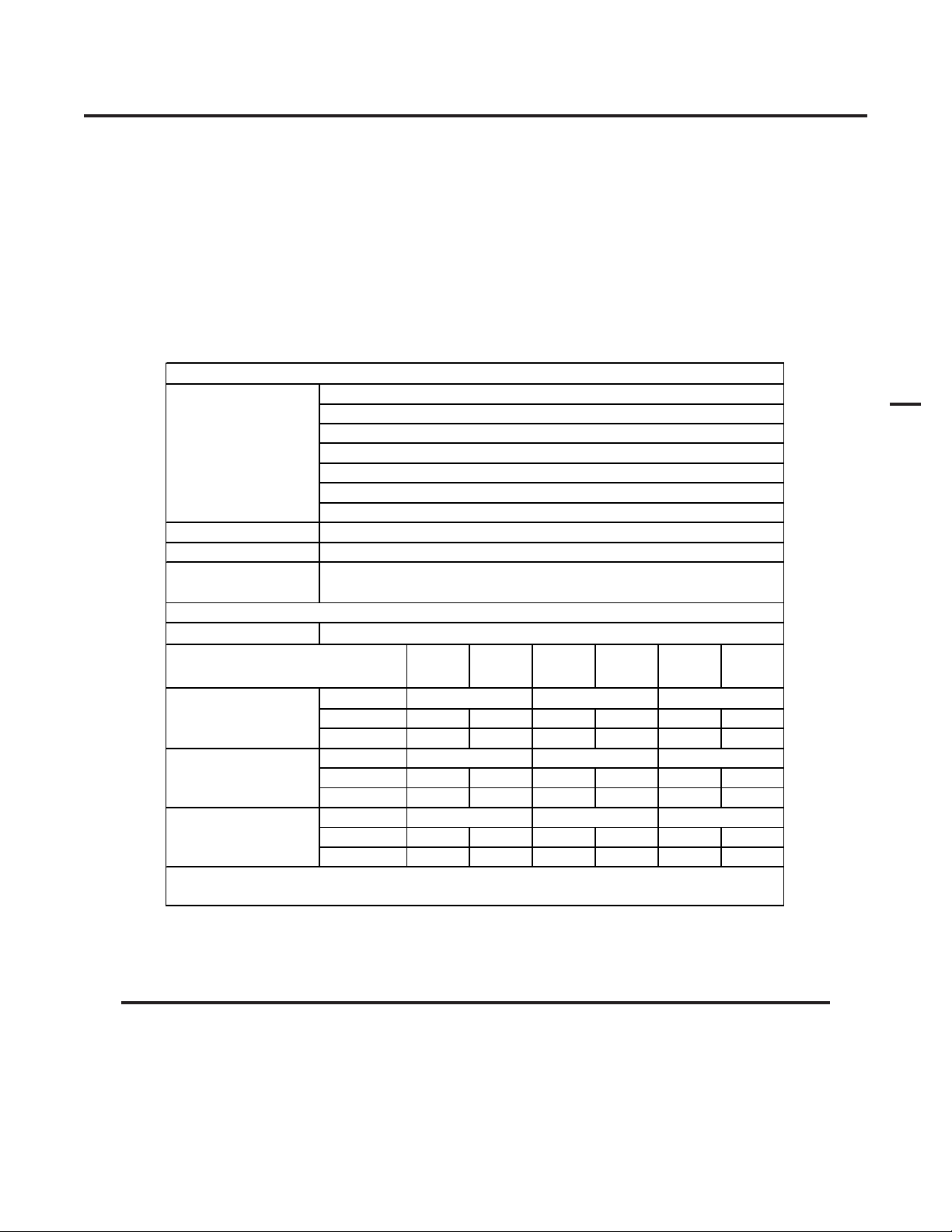
Power Supply Dimensions & Weight Ventilation Clearance Requirements
s
Art # A-03379
83 lb / 37.6 kg
150 mm
17.3 in /
439 mm
6"
27.5 in / 696 mm
12.4 in /
2
A-03572
315 mm
2.03 Input Wiring Specifications
CutMaster 101 Input Wiring Specification
Input Power Input Current Input Suggested Sizes (See Notes)
Voltage Freq. 1-Ph 3-Ph 1-Ph 3-Ph Fuse (Amps) Wire (AWG) Wir e (Canada)
(Volts) (Hz) (kVA) (kVA) (Amps) (Amps) 1-Ph 3-Ph 1-Ph 3-Ph 1-Ph 3-Ph
208 50 14.4 69 90 6 6
208 60 15.6 75 90 6 6
230 50 15 65 80 6 6
230 60 15.5 67 80 6 6
400 50/60 13.9 20 30 10 10
460 60 18 39 50 10 10
460601620301212
600 60 13.5 13 20 12 12
Line Voltages wi th Suggested Circ ui t Protec tion and Wire Si z es
Based on Nati onal Electric Code and Canadian Electri cal Code
24"
0.6 m
6"
150 mm
6"
150 mm
CE CutMaster 101 Input Wiring Specifications
Input Suggested Sizes (See Notes)
Voltage Frequency 3-Ph 3-Ph Fuse (Amps)
Power Input Current Input
Wire (mm
2
)
(Volts) (Hz) (kVA) (Amps) 3-Ph 3-Ph
400 / 415 50 13.9 20 25 4
Line Voltages with Suggested Circuit Protection and Wire Sizes
Based on National Electric Code and Canadian Electric Code
NOTES
Refer to Local and National Codes or local authority having jurisdiction for proper wiring requirements.
Cable size is de-rated based on the Duty Cycle of the equipment.
The suggested sizes are based on flexible power cable with power plug installations. For hard-wired installations
refer to local or national codes.
Cable conductor temperature used is 167° F (75° C).
An energy limiting fuse UL Class RK-1 (examples: BUSS LPS / LPN-RK or Gould-Shawmut AZK-A6K) should be
used to minimize damage to Plasma Cutting, Welding or power distribution equipment.
NEVER use replaceable element fuses like UL Class H, or "one-time" fuses like UL Class K5.
INTRODUCTION 2-2 Manual 0-4642
Page 19
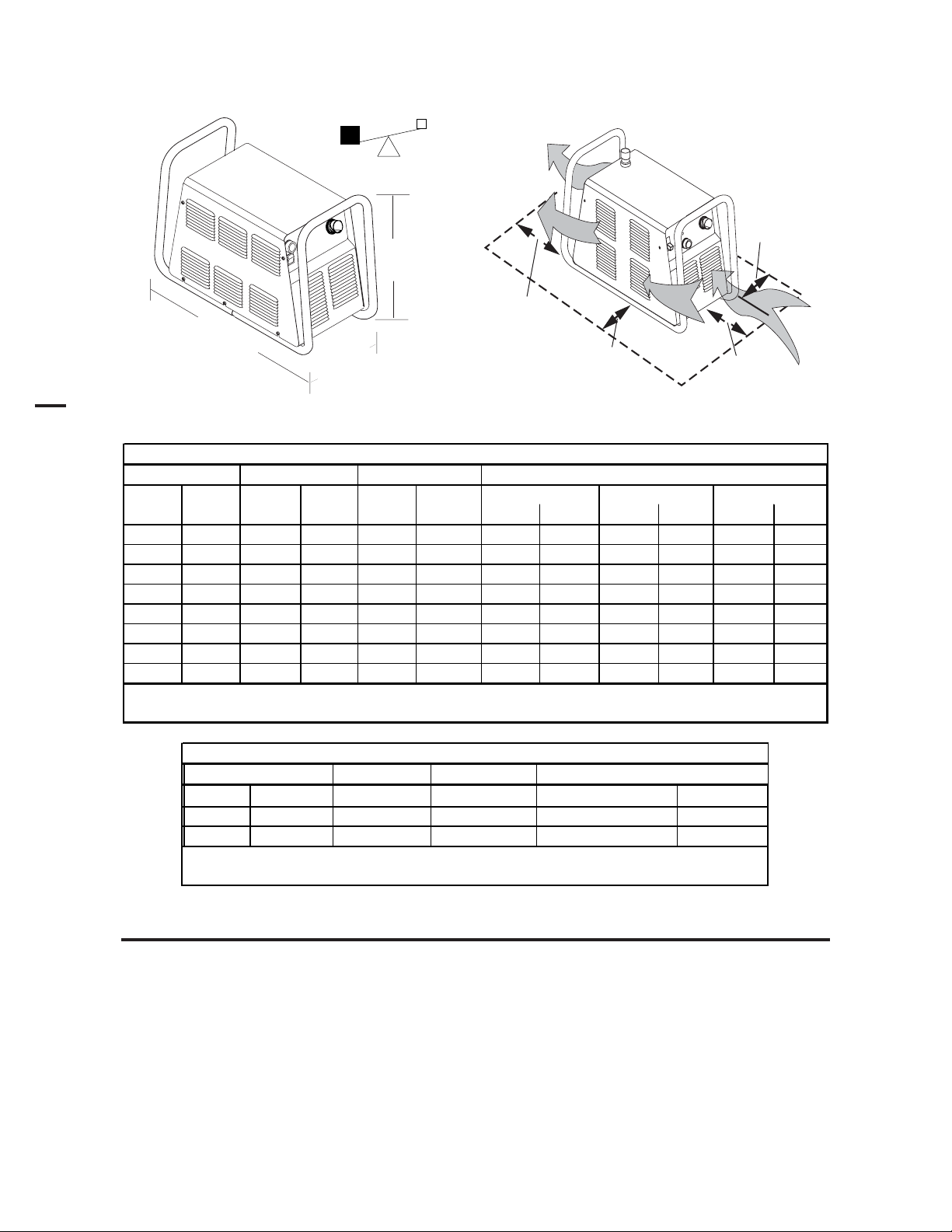
2.04 Power Supply Features
Handle and Leads Wrap
Art # A-04507
Control Panel
Torch Leads Receptacle
2
Work Cable
and Clamp
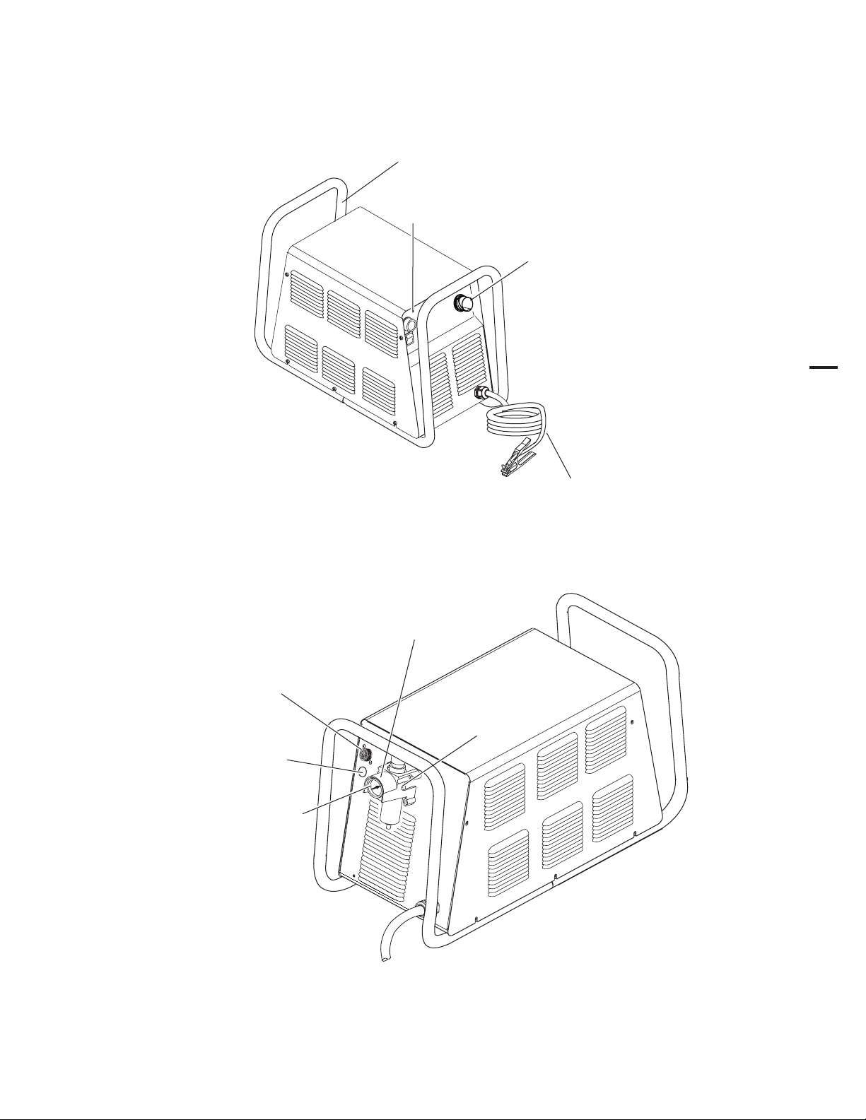
Gas Pressure Regulator / Filter Assembly
CPC Connector for
Thermal Dynamics CNC Controller
Knockout for Alternate
CNC Controller
Wire Harness
Gas Pressure Gauge
Input Power Cord
Gas Inlet Port
Art # A-04214
Manual 0-4642 2-3 INTRODUCTION
Page 20

2.05 Power Supply Options and Accessories
Section 6, Parts Lists, provides catalog numbers and ordering information.
A. Single-Stage Air Filter Kit
For use with compressed air shop systems. Filters moisture and particulate matter from the air stream to at least
0.85 microns. This filter increases performance and improves consumables parts life.
B. Two Stage Air Filter Kit
For use on compressed air shop systems. Filters moisture and contaminants from the air stream to at least 5.0
microns. This filter is pre-assembled at the factory and needs only to be installed on the power supply.
C. High Pressure Regulators
High pressure regulators are available. The regulators are used to set the proper compressed air pressure.
2
Regulators should not be installed with In-Line Air Filters.
D. Extended Work Cable with Clamp
As an alternative to the standard 20 ft / 6.1 m work cable & clamp on the power supply, a 50 ft / 15.2 m work cable
with clamp is available.
E. Multi-Purpose Cart
Rugged steel cart on easy-rolling rear wheels and front-mounted swivel casters. Provides maximum mobility for
the power supply and can also serve as a display cart. Top shelf is 12" / 305 mm x 20" / 508 mm. Steel handle is
30" / 762 mm high.
F. Wheel Kit
A kit with easy-rolling wheels, for maximum portability for the power supply.
G. Nylon Dust Cover
Nylon canvas power supply dust cover with water resistant finish, large outer pocket for storing manuals or spare
consumables, and adjustable draw cord for tight fit.
NOTE
INTRODUCTION 2-4 Manual 0-4642
Page 21
2.06 Torch Specifications
s
s
E
:
E
SL100SV Machine Torch Specifications
Ambient Temperature 104° F / 40° C
Duty Cy c le
Maximum Current 100 Amps
Voltage (V
Arc Striking Voltage 7kV
Type of Cooling
Current Rating Up to 100 Amps, DC, Straight Polarity
Gas (Plasma and Secondary)
Operating Pressure (Varies According to
Power Supply and Torch Leads Length)
Maximum Input Pressure 125 psi / 8.6 bar
Gas Flow
NOT
Thermal Dynamics CutMaster 51, CutMaster 81, CutMaster 101, CutMaster 151
(Refer to NOTE)
) 500V
p eak
: Operating pressure varies with operating amperage and torch leads length.
Torch duty cycle is greater than power supply duty cycle.
Torch Ratings
100% @ 100 Amps @ 400 scfh
Combination of Ambient Air and
Gas Flow Through Torc h
Gas Requirement
Compressed Air (
300 - 500 scfh / 142 - 235 lpm
Torch Leads Length
25' / 7.6 m, with ATC Connector
35' / 10.6 m, with ATC Connector
50' / 15.2 m, with ATC Connector
Plasma Power Supply Used With
NOT
60 - 75 psi
4.1 - 5.2 bar
ONLY
)
2
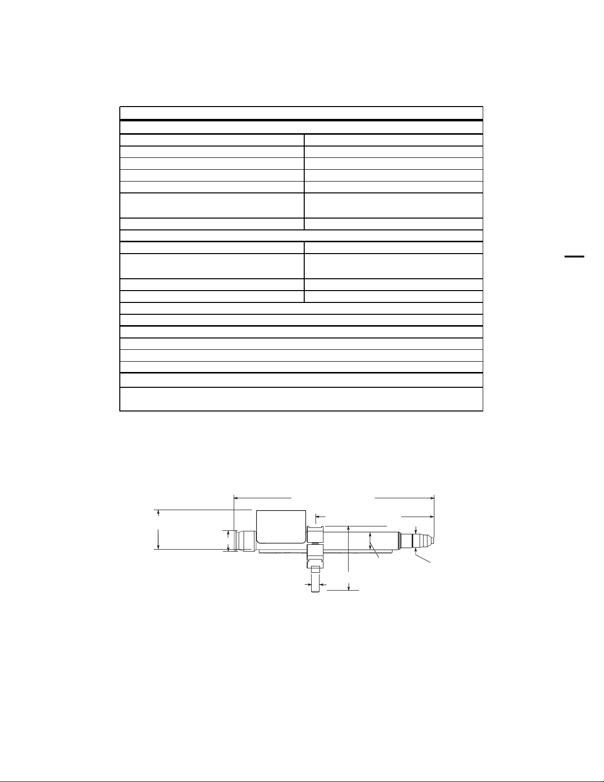
A. Torch Configuration
The standard machine torch has a positioning tube with rack & pinch block assembly.
2.875” / 73 mm
1.75" / 44.5 mm
15.875" / 403 mm
0.625" /
16 mm
9.285" / 236 mm
1.375" / 35 mm
4.95" / 126 mm
1.175" / 30 mm
Art # A-07402
Manual 0-4642 2-5 INTRODUCTION
Page 22
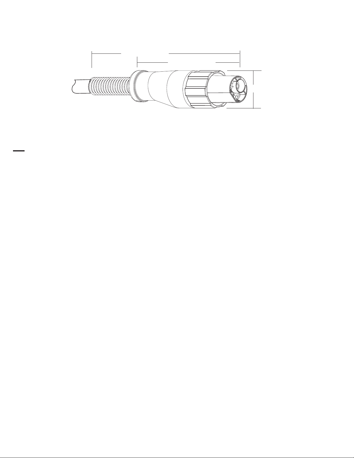
B. Torch Connector Dimensions
Art # A-04056
C. Torch Parts
Start Cartridge, Electrode, Tip, Shield Cup Body, Shield Cap
D. Parts - In - Place (PIP)
2
Torch Head has built - in switch
12 vdc circuit rating
E. Direct Contact Hazard
For exposed tip the recommended standoff is 3/16 inches / 4.7 mm.
8.5" / 216 mm
5.375" / 137 mm
1.9" / 50 mm
2.07 Torch Options and Accessories
These items can adapt a standard system to a particular application or further enhance performance (refer to Section 6
for ordering information).
• Spare Parts Kits - Various kits containing replacement consumable torch parts.
• Pinion Assembly (for machine torches)
• Leather Leads Covers
INTRODUCTION 2-6 Manual 0-4642
Page 23
2.08 Introduction to Plasma
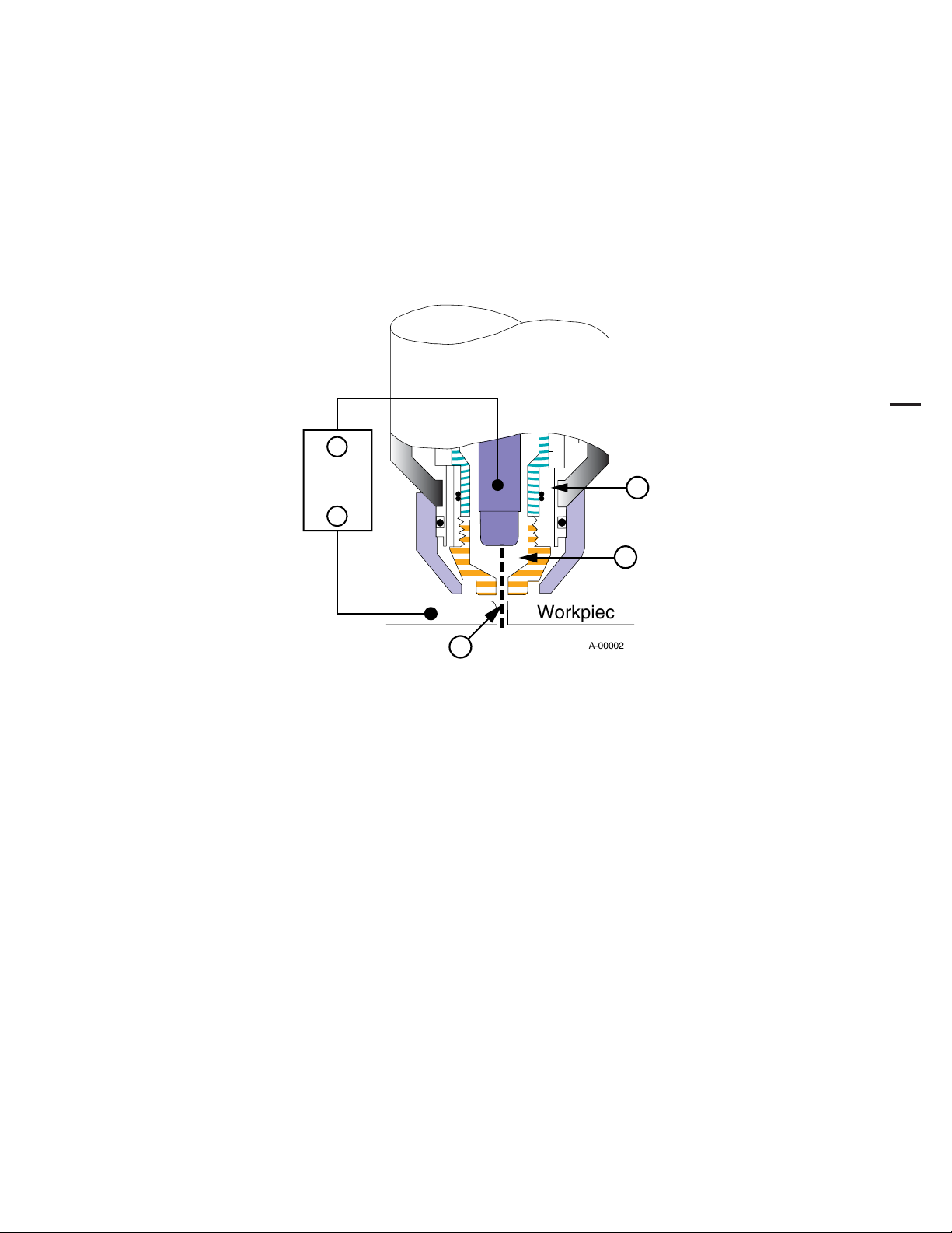
A. Plasma Gas Flow
Plasma is a gas which has been heated to an extremely high temperature and ionized so that it becomes electrically
conductive. The plasma arc cutting and gouging processes use this plasma to transfer an electrical arc to the workpiece. The
metal to be cut or removed is melted by the heat of the arc and then blown away.
In a Plasma Cutting Torch a cool gas enters Zone B, where a pilot arc between the electrode and the torch tip heats and
ionizes the gas. The main cutting arc then transfers to the workpiece through the column of plasma gas in Zone C.
_
Power
Supply
+
A
2
B
Workpiece
C
Typical Torch Head Detail
By forcing the plasma gas and electric arc through a small orifice, the torch delivers a high concentration of heat to a small
area. The stiff, constricted plasma arc is shown in Zone C. Direct current (DC) straight polarity is used for plasma cutting, as
shown in the illustration.
Zone A channels a secondary gas that cools the torch. This gas also assists the high velocity plasma gas in blowing
the molten metal out of the cut allowing for a fast, slag - free cut.
B. Gas Distribution
The single gas used is internally split into plasma and secondary gases.
The plasma gas flows into the torch through the negative lead, through the start cartridge, around the electrode,
and out through the tip orifice.
The secondary gas flows down around the outside of the torch start cartridge, and out between the tip and shield
cup around the plasma arc.
A-00002
C. Pilot Arc
When the torch is started a pilot arc is established between the electrode and cutting tip. This pilot arc creates a
path for the main arc to transfer to the work.
Manual 0-4642 2-7 INTRODUCTION
Page 24

D. Main Cutting Arc
DC power is also used for the main cutting arc. The negative output is connected to the torch electrode through the
torch lead. The positive output is connected to the workpiece via the work cable and to the torch through a pilot
wire.
E. Parts - In - Place (PIP)
The torch leads include a ‘Parts - In - Place’ (PIP) circuit. When the torch shield cup is properly installed, it closes
a switch. The torch will not operate if this switch is open.
2
To Control
Cable Wiring
PIP Switch
Parts - In - Place Circuit Diagram
Shield Cup
A-03504
INTRODUCTION 2-8 Manual 0-4642
Page 25

SECTION 3: INSTALLATION
3.01 Unpacking
1. Use the packing lists to identify and account for each item.
2. Inspect each item for possible shipping damage. If damage is evident, contact your distributor and / or shipping
company before proceeding with the installation.
3. Record Power Supply and Torch model and serial numbers, purchase date and vendor name, in the information
block at the front of this manual.
3.02 Lifting Options
The Power Supply includes a handle for hand lifting only. Be sure unit is lifted and transported safely and securely.
WARNINGS
Do not touch live electrical parts.
Disconnect input power cord before moving unit.
FALLING EQUIPMENT can cause serious personal injury and can damage equipment.
HANDLE is not for mechanical lifting.
3
• Only persons of adequate physical strength should lift the unit.
• Lift unit by the handle, using two hands. Do not use straps for lifting.
• Use optional wheel kit, cart or similar device of adequate capacity to move unit.
• Place unit on a proper skid and secure in place before transporting with a fork lift or other vehicle.
Manual 0-4642 3-1 INSTALLATION
Page 26

3.03 Primary Input Power Connections
CAUTION
Check your power source for correct voltage before plugging in or connecting the unit. The primary power
source, fuse, and any extension cords used must conform to local electrical code and the recommended circuit
protection and wiring requirements as specified in Section 2.03.
A. Connections to 208 / 230-Volt Power
The 208 / 230-Volt power supply includes a factory-installed input power cable and plug.
1. Check your power source for correct voltage before plugging in the unit.
2. Connect the input power cable (or close the main disconnect switch) to supply power to the system.
CAUTION
The primary power source and power cable must conform to local electrical code and the recommended circuit
protection and wiring requirements (refer to table in Section 2.03).
B. Connections to 400-Volt, 415-Volt, 460-Volt, or 600-Volt Three-Phase Power
3
These Power Supplies are equipped with a four-conductor input power cable for three-phase input power. The 460-Volt Power
Supply will accept 460-VAC, Single-Phase input power with a change of input power cable.
1. Check your power source for correct voltage before plugging in the unit.
2. The input cable's outer covering is stripped back at the factory to expose the individual wires at the free end of the cable.
3. Connect the ends of the individual wires to a customer supplied plug or main disconnect as follows:
CAUTION
The primary power source and power cable must conform to local electrical code and the recommended circuit
protection and wiring requirements (refer to table in Section 2 ). All the input cable wires must be connected for
three-phase operation.
• Green / Yellow wire to Ground.
• Remaining wires to L1, L2, L3 input.
4. Connect the input power cable (or close the main disconnect switch) to supply power to the system.
INSTALLATION 3-2 Manual 0-4642
Page 27
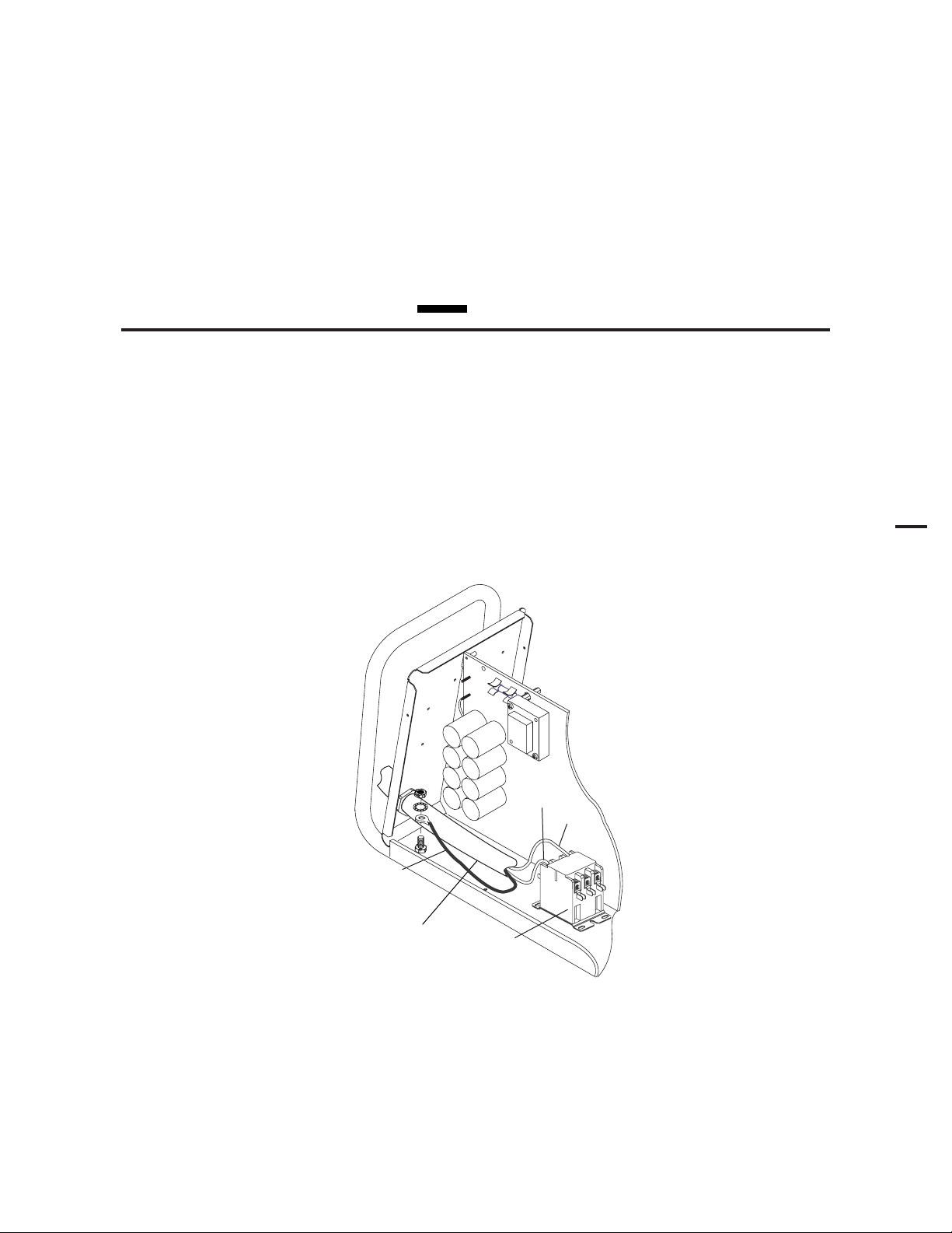
C. Connections to 460-Volt Single - Phase Power
The 460-Volt Power Supply will accept 460-VAC, Single-Phase input power with a change of input power cable.
1. Remove the Power Supply cover per section 5.09-A.
2. Disconnect the original input power cable from the main input contactor and the chassis ground connection.
3. Loosen the through-hole protector on the back panel of the power supply. Pull the original power cable out of the power
supply.
4. Pass a customer-supplied, three-conductor input power cable through the access opening in the back panel of the power
supply. Refer to Section 2 for power cable specifications.
CAUTION
The primary power source and power cable must conform to local electrical code and the recommended circuit
protection and wiring requirements (refer to table in Section 2.03).
5. Strip back the insulation on the individual wires.
6. Connect to main input contactor as follows:
• Line 1 wire to terminal L1.
• Line 3 wire to terminal L3.
7. Connect the ground wire to Ground (Earth). The Ground wire connection requires a ring terminal.
8. Tighten the through-hole protector to secure the power cable.
3
L1
L3
L1 L2 L3
Ground Wire
with Ring
Terminal
Input Cable
A-03041
Main Input
Contactor
Input Power Connections, 460 VAC, Single-Phase
9. Replace the Power Supply cover.
10. Connect the input power cable (or close the main disconnect switch) to supply power to the system.
Manual 0-4642 3-3 INSTALLATION
Page 28
3
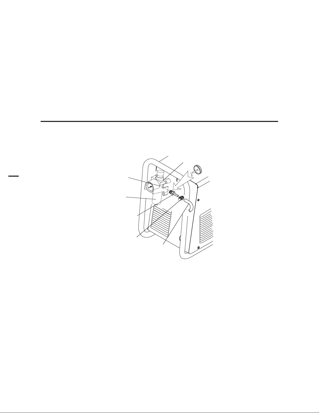
3.04 Gas Connections
A. Connecting Gas Supply to Unit
Use only compressed air with this power supply.
An in-line pneumatic dryer & evaporator type air filter, capable of filtering to at least 5 microns, is required when using air from a
compressor. This type filter will insure that moisture, oil, dirt, chips, rust particles, and other contaminants from the supply hose
do not enter the torch. For highly automated applications, a refrigerated drier may be used.
The connection is the same for compressed air from a compressor from high pressure cylinders. Refer to subsection 3.4-B or 3.4C if an additional air line filter is to be installed.
1. Connect the air line to the inlet port. The illustration shows typical fittings as an example. Other fittings can be
used.
NOTE
For a secure seal, apply thread sealant to the fitting threads, according to manufacturer's instructions. Do not use
Teflon tape as a thread sealer, as small particles of the tape may break off and block the small air passages in the torch.
Regulator/Filter
Assembly
Inlet Port
Bowl
1/4 NPT to 1/4"
(6mm) Fitting
Hose Clamp
Art # A-02999
Air Connection to Inlet Port
Gas Supply
Hose
INSTALLATION 3-4 Manual 0-4642
Page 29
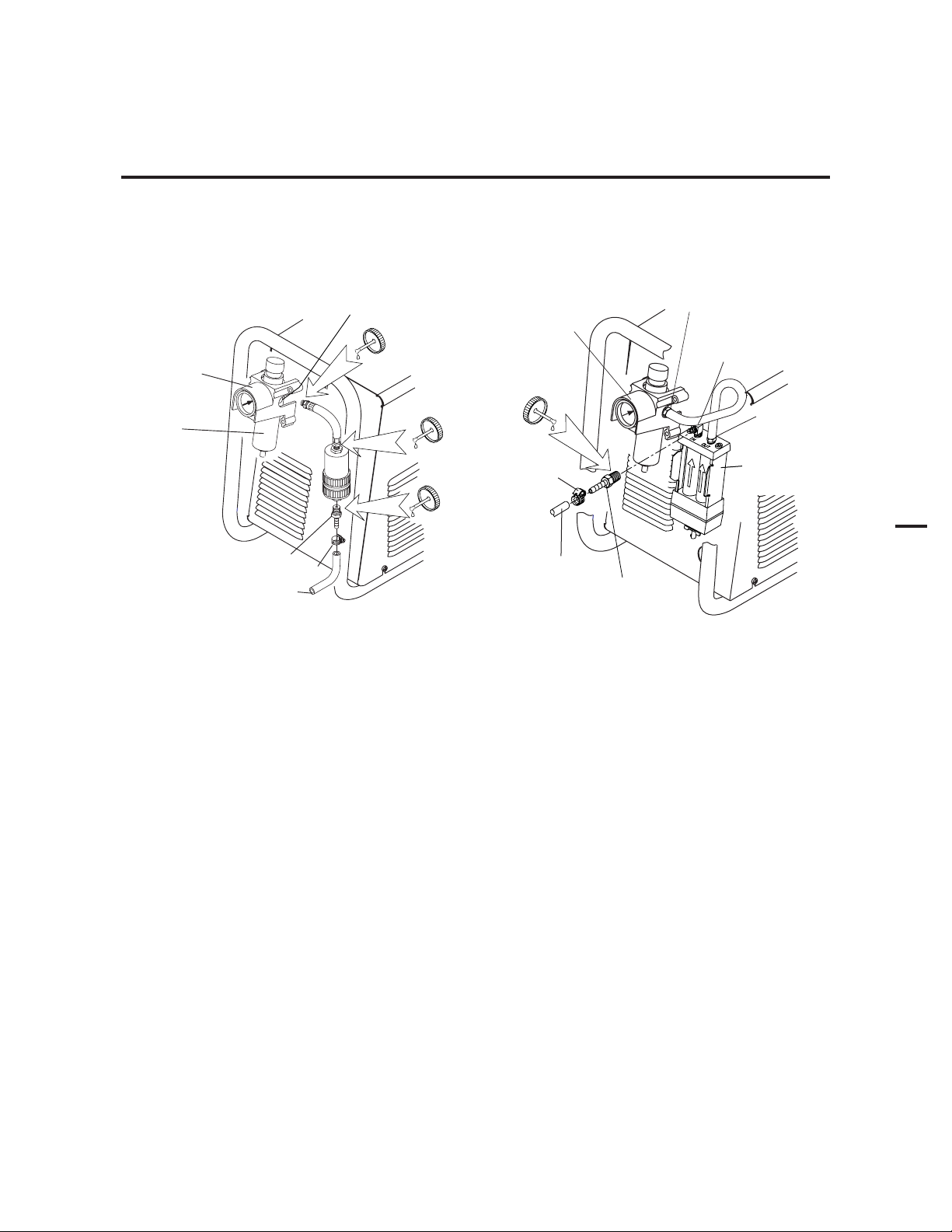
B. Optional Air Filters
t
1. Connect the Filter as illustrated. Use only Synflex or equivalent grade hose. The illustrations show typical fittings as an
example.
NOTE
For a secure seal, apply thread sealant to the fitting threads, according to the maker's instructions. Do Not use
Teflon tape as a thread sealer, as small particles of the tape may break off and block the small air passages in the
torch. Connect as follows:
Regulator Inlet Port
2-Stage Filter
Inlet Port (IN)
Regulator/Filter
Assembly
Bowl
Inlet Port
Regulator/Filter
Assembly
Hose
Clamp
1/4 NPT Hose Fitting
Hose Clamp
1/4" (6 mm) Gas Supply Hose
Art # A-03000
1/4" (6 mm) Gas
Supply Hose)
1/4 NPT
Hose Fitting
Optional Single-Stage Filter Installation Optional Two-Stage Filter Installation
Outlet Por
(OUT)
Two Stage
Filter
Assembly
3
Art # A-03004
Manual 0-4642 3-5 INSTALLATION
Page 30

3
D. Using High Pressure Air Cylinders
When using high pressure air cylinders as the air supply:
1. Refer to the manufacturer’s specifications for installation and maintenance procedures for high pressure regulators.
2. Examine the cylinder valves to be sure they are clean and free of oil, grease or any foreign material. Briefly open
each cylinder valve to blow out any dust which may be present.
3. The cylinder must be equipped with an adjustable high-pressure regulator capable of outlet pressures up to 100 psi (6.9 bar)
maximum and flows of at least 500 scfh (236 lpm).
4. Connect supply hose to the cylinder.
NOTE
Pressure should be set at 100 psi (6.9 bar) at the high pressure cylinder regulator.
Supply hose must be at least 1/4 inch (6 mm) I.D.
For a secure seal, apply thread sealant to the fitting threads, according to manufacturer's instructions. Do Not use
Teflon tape as a thread sealer, as small particles of the tape may break off and block the small air passages in the torch.
INSTALLATION 3-6 Manual 0-4642
Page 31

3.05 Torch Connections
If necessary, connect the torch to the Power Supply. Connect only the Thermal Dynamics model SL100 Torch (with ATC
connector) to this power supply. Maximum torch leads length is 50 feet / 15.2 m.
WARNING
Disconnect primary power at the source before connecting the torch.
1. Align the ATC male connector (on the torch lead) with the female receptacle. Push the male connector into the
female receptacle. The connectors should push together with a small amount of pressure.
2. Secure the connection by turning the locking nut clockwise until it clicks. DO NOT use the locking nut to pull
the connection together. Do not use tools to secure the connection.
3. The system is ready for operation.
Art # A-06755
ATC Female Receptacle
(Panel Mounted)
1
3
ATC Male
Connector
Torch Leads
2
Connecting the Torch to the Power Supply
Manual 0-4642 3-7 INSTALLATION
Page 32

B. Check Air Quality
To test the quality of air:
1. Put the ON / OFF switch in the ON (up) position.
2. Put the RUN / RAPID AUTO RESTART / SET switch in the SET (down) position.
3. Place a welding filter lens in front of the torch and turn on the air. Any oil or moisture in the air will be visible on the lens.
Do not start an arc!
A
3
40
1
20
60
2
80
Art # A-03577
INSTALLATION 3-8 Manual 0-4642
Page 33

3.06 Torch Installation
WARNING
Disconnect primary power at the source before disassembling the torch or torch leads.
The machine torch includes a positioning tube with rack and pinch block assembly.
1. Mount the torch assembly on the cutting table.
2. To obtain a clean vertical cut, use a square to align the torch perpendicular to the surface of the workpiece.
Pinch Block
Assembly
3
Square
Workpiece
A-02585
Machine Torch Set-Up
3. The proper torch parts (shield cup body, shield cap, tip, start cartridge, and electrode) must be installed for the type of
operation. Refer to Section 3.07, Torch Parts Selection for details.
Manual 0-4642 3-9 INSTALLATION
Page 34

3.07 Torch Parts Selection
1. Check the torch for proper consumable parts. The parts supplied in the torch may not be correct for the operator's chosen
amperage level. The torch parts must correspond with the type of operation.
3
Torch Head
Art # A-04173
Electrode
Start Cartridge
Tip
Shield Cup Body
Ohmic Clip
(If Installed)
Deflector
Shield Cap
INSTALLATION 3-10 Manual 0-4642
Page 35

3.08 Power Supply Connection to SC-11 Standoff Control
The power supply includes an Automation Interface PC Board connected to a CPC connector on the power supply rear panel.
For connection to the Thermal Dynamics SC-11 Standoff Control, align and connect the cable from the Standoff Control to the
CPC connector. Check for a secure connection.
CPC Connector for
Thermal Dynamics CNC Controller
Connector for SC-11
Standoff Control / CNC
3
Art # A-04075
Manual 0-4642 3-11 INSTALLATION
Page 36

3
3.09 Power Supply Connection to Alternate Standoff Control
The Power Supply rear panel includes a knockout to accept wiring between the Automation Interface PC Board and alternate CNC
controls. The Automation Interface PC board includes a terminal strip for connection to alternate CNC controls.
To connect an alternate CNC Control to the Power Supply:
1. Remove the Power Supply Cover.
2. Carefully open the lower knockout (below the factory-installed CNC connector) on the Power Supply rear panel.
Knockout for Alternate
CNC Controller
CPC Connector for
Thermal Dynamics
CNC Controller
Art # A-04178
3. Install a customer-supplied through-hole protector ('Strain Relief') in the lower knockout hole.
4. Route the wire harness from the alternate CNC Control through the through-hole protector.
INSTALLATION 3-12 Manual 0-4642
Page 37

5. Connect the wire harness from the alternate CNC Control to the 20-position terminal strip (labeled 'J2') on the Automation
Interface PC Board. Refer to the illustration.
a. For divided voltage output, connect to terminals J2-11 (negative) and J2-9 (positive) on the Interface PC Board..
b. For raw arc voltage, connect to terminals E2 (positive) and E1 (negative) on the Output Power PC Board.
NOTE
There is no need to disconnect the factory-installed wire harness from the J4 terminal strip.
Open
Arc Volts Negative - (Proprietary)
Open
Logic Common
Arc Volts - Positive (Proprietary)
Remote Current Control (Optional)
Open
Remote Current Control (Optional)
Remote Current Control (Optional)
Divided Output (Negative)
Open
Divided Output (Positive)
Open
Open
Open
OK to Move
OK to Move
Open
Torch Switch (Negative)
Torch Switch
(Positive)
20
19
18
17
16
To Main PC Board
Terminal J27-3
To Main PC Board
Terminal J27-2
To Main PC Board
Terminal J27-1
Installed only with
Optional Remote Current Control
15
14
13
12
11
10
8
9
6
7
5
Automation Interface PC Board
Output Power PC Board
3
4
2
Terminal Block J2
Raw Arc Voltage
Connection Points
1
3
Art # A-04149
E1(-)
E2 (+)
Alternate CNC Controller Connections to Automation Interface Board
6. Tighten the through-hole protector ('strain relief') to secure the CNC cable to the power supply.
Manual 0-4642 3-13 INSTALLATION
Page 38

3
3.10 Automation Interface PC Board Set-up
The Automation Interface PC board includes switches that must be set to adapt the Interface Board to the automation system
being used.
NOTE
The switches are factory-set for the Thermal Dynamics SC-11 Standoff Control.
For operation with any other CNC equipment, refer to the CNC system documents to determine the division factor the CNC
system requires. Proceed as follows:
1. Set the interface control board switches as indicated in the appropriate chart in the Appendix pages. The division factors
are listed in the right-hand column of each chart.
Automation Interface PC Board
Automation
Interface
PC Board
Pilot PC
Board
8 7 6 5 4 3 2 1
2. Re-install the Power Supply cover.
Output Power
PC Board
Art # A-03902
Switches
Art # A-03757
INSTALLATION 3-14 Manual 0-4642
Page 39

3.11 Optional Remote Current Control Harness Installation
1. Locate the power supply Pot/LED Board just inside the power supply front panel.
Pot / LED Board
3
Art # A-03964
2. Disconnect and remove the wire harness between the Pot/LED Board and receptacle J22 on the Main PC Board. Keep the
harness for possible future use.
3. The kit includes a wire harness with 3 connectors. Install the harness as follows:
Connector Plugs
To Automation
Interface Board
Receptacle J3
To Pot/LED Board
To Main PC Board
Receptacle J27
Receptacle J14
Art # A-03945
4. Ensure that the wire harness will not interfere with the fit of the power supply cover against the top edge of the
power supply center chassis. Use wire ties as needed to secure the wire harness.
NOTE
Installation of this harness disables the output current control (A) on the front panel of the power supply. Use the
CNC controller to control the output current of the power supply.
5. Re-install the Power Supply cover.
Manual 0-4642 3-15 INSTALLATION
Page 40

3
This Page Left Blank
INSTALLATION 3-16 Manual 0-4642
Page 41

SECTION 4: OPERATION
4.01 Product Features
A. Power Supply Front Panel Controls and Indicators
AC Indicator
A) Output Current Control
(
Sets the desired output current. At output settings
over 40 Amps, the power supply automatically reduces output current to 40 Amps if the torch tip
touches the workpiece.
Art # A
-03744
A
40
20
60
80
Steady light indicates power supply is ready for
operation. Blinking light indicates unit is in protective interlock mode. Shut unit off, shut off or
disconnect input power, correct the fault, and restart the unit. Refer to Section 5 for details.
TEMP Indicator
Indicator is normally OFF. Indicator is ON
when internal temperature exceeds normal
limits. Shut unit OFF; let the unit cool before
continuing operation.
GAS Indicator
Indicator is ON when minimum input gas
pressure for power supply operation is
present. Minimum pressure for power supply operation is not sufficient for torch operation.
4
ON / OFF Switch
Controls input power to the power supply.
is ON, is OFF.
RUN / RAPID AUTO RESTART / SET Switch
RUN (up) position is for general torch operation.
RAPID AUTO RESTART (middle) position is for an uninterrupted restart, when cutting
expanded metal or in trimming operations.
SET (down) position is for setting gas pressure and purging lines.
Manual 0-4642 4-1 OPERATION
DC Indicator
Indicator is ON when DC output circuit is
active.
Page 42
4.02 Preparations For Operating
Perform the following steps at the start of each operating session:
WARNING
Disconnect primary power at the source before assembling or disassembling power supply, torch parts, or torch and
leads assemblies.
A. Torch Parts Selection
Check the torch for proper assembly and appropriate torch parts. The torch parts must correspond with the type of
operation, and with the amperage output of this Power Supply (80 amps maximum).
B. Torch Connection
Check that the torch is properly connected. Only Thermal Dynamics model SL100 Torches may be connected to
this Power Supply.
C. Check Primary Input Power Source
1. Check the power source for proper input voltage. Make sure the input power source meets the power requirements for the unit per Section 2, Specifications.
2. Connect the input power cable (or close the main disconnect switch) to supply power to the system.
4
D. Gas Selection
Ensure compressed air source meets requirements (refer to Section 3.4). Check connections and turn gas supply on.
Place the ON - OFF Switch on the Power Supply to the ON position. If the Run - Rapid Auto Restart - Set switch is in SET
position, gas will flow. If the switch is in RUN or Rapid Auto Restart position there will be no gas flow.
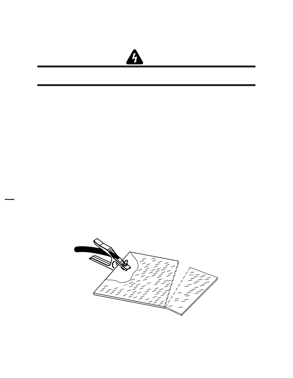
E. Connect Work Cable
Clamp the work cable to the workpiece or cutting table. The area must be free from oil, paint and rust. Connect only to the main
part of the workpiece; do not connect to the part to be cut off.
Art # A-04509
OPERATION 4-2 Manual 0-4642
Page 43

F. Power On
Place the Power Supply ON / OFF switch to the ON (up) position. AC indicator turns on. Gas indicator
turns on if there is sufficient gas pressure for power supply operation.
NOTE
Minimum pressure for power supply operation is lower than minimum for torch operation.
A
40
20
60
80
Art # A-03580
4
Manual 0-4642 4-3 OPERATION
Page 44

G. Set Operating Pressure
1. Place the Power Supply RUN / Rapid Auto Restart / SET switch to the SET (down) position. Gas will flow.
A
4
40
1
2. Adjust gas pressure per the settings chart.
20
80
60
Art # A-03577
65 - 75 psi /
4.5 - 5.2 bar
2
Pressure Control Knob
CutMa ster 101
Gas Pressure Settings
Leads
Length
40A Cut ting
60A Cut ting
80A Cut ting
Up to 25'
(7.6 m)
65 psi
4.5 bar
70 psi
4.8 bar
65 psi
4.5 bar
Over 25'
(7.6 m)
70 psi
4.8 bar
75 psi
5.2 bar
70 psi
4.8 bar
Art #A-04181
OPERATION 4-4 Manual 0-4642
Page 45
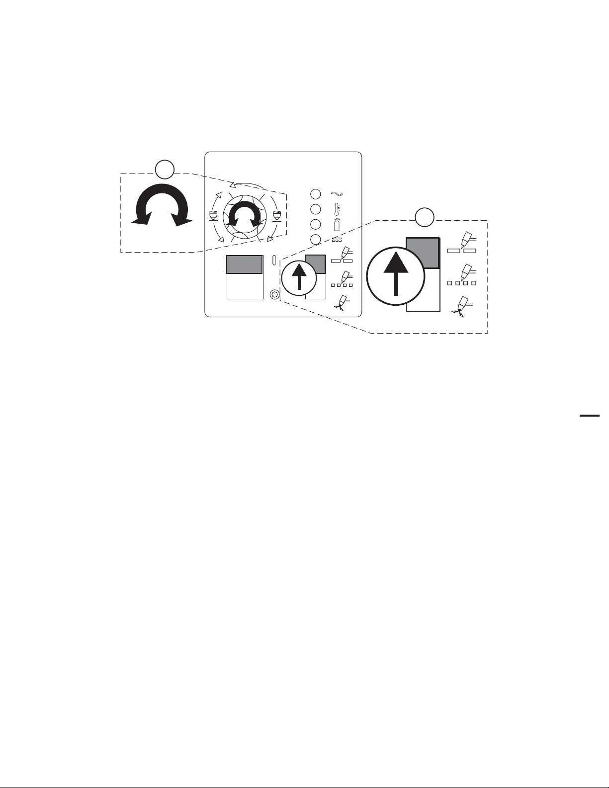
H. Select Current Output Level
1. Place RUN / Rapid Auto Restart / SET to RUN (up) or Rapid Auto Restart (center) position. Gas flow stops.
2. Set the current output level, up to 80 amps for standoff cutting. At output settings higher than 40 amps, the power supply
automatically reduces output current to 40 amps if the torch tip contacts the workpiece.
2
40
A
60
1
20
Art # A-03579
I. Cutting Operation
When the torch leaves the workpiece during cutting operations with the RUN / Rapid Auto Restart / SET switch in the RUN
(up) position, there is a brief delay in restarting the pilot arc. With the switch in the 'Rapid Auto Restart' (middle) position,
when the torch leaves the workpiece the pilot arc restarts instantly, and the cutting arc restarts instantly when the pilot arc
contacts the workpiece. Use the 'Rapid Auto Restart' position when cutting expanded metal or gratings, or in trimming
operations when an uninterrupted restart is desired.
J. Typical Cutting Speeds
80
4
Cutting speeds vary according to torch output amperage, the type of material being cut, and operator skill.
Output current setting or cutting speeds may be reduced to allow slower cutting while still producing cuts of excellent quality.
K. Postflow
De-activate the start signal (provided by the CNC Control) to stop the cutting arc. Gas continues to flow for approximately 6
seconds. During post - flow, if the user activates start signal, the pilot arc starts. The main arc transfers to the workpiece if the
torch tip is within transfer distance to the workpiece.
Manual 0-4642 4-5 OPERATION
Page 46
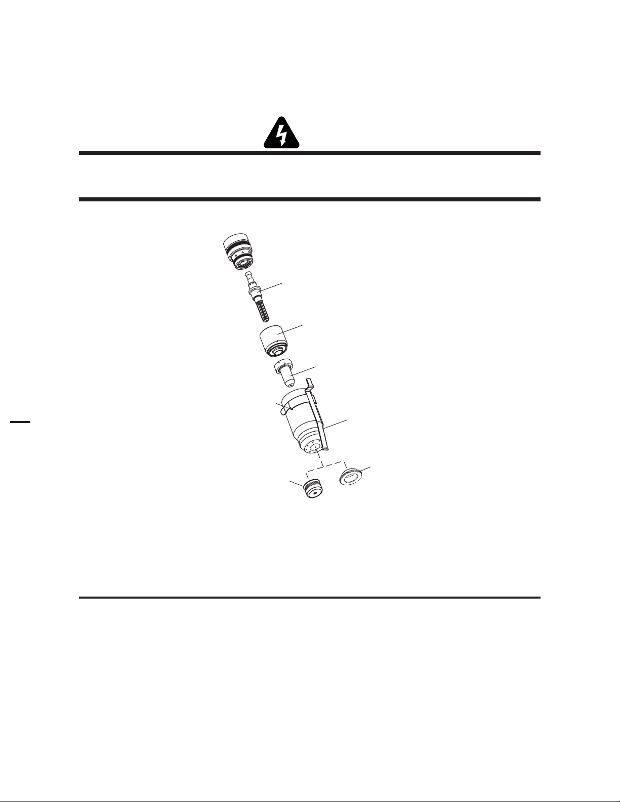
4.03 Selection, Inspection and Replacement of Consumable Torch Parts
The type of operation to be done determines the torch parts to be used. Change the torch parts for a different operation as
follows:
WARNINGS
Disconnect primary power to the system before disassembling the torch or torch leads.
DO NOT touch any internal torch parts while the AC indicator light of the Power Supply is ON.
4
Torch Head
Art # A-04173
Electrode
Start Cartridge
Tip
Shield Cup Body
Ohmic Clip
(If Installed)
Deflector
Shield Cap
Consumable Parts
1. Unscrew and remove the shield cup assembly from the torch head. Inspect the cup for damage. Wipe it clean or replace if
damaged.
NOTES
The shield cup holds the tip and start cartridge in place.
Slag built up on the shield cup that cannot be removed may affect the performance of the system.
OPERATION 4-6 Manual 0-4642
Page 47

2. Remove the tip. Check for excessive wear (indicated by an elongated or oversized orifice). Clean or replace the tip
if necessary.
Good Tip
Worn Tip
A-03406
Tip Wear
3. Remove the start cartridge. Check for excessive wear, plugged gas holes, or discoloration. Check the lower end
fitting for free motion. Replace if necessary.
Spring-Loaded Cylinder
at Full Compression
1/8” (3 mm)
Spring-Loaded Cylinder
at Full Extension
Art # A-07168
4. Pull the Electrode straight out of the Torch Head. Check the end of the electrode for excessive wear. Replace the
electrode if wear is greater than 0.062" / 1.5 mm or if the wear is excessively off-center. Refer to the following figure.
0.062" (1.5 mm)
Art # A-04057
Electrode Wear
Electrode Wear
5. Reinstall the Electrode by pushing it straight into the torch head until it clicks.
6. Reinstall the start cartridge and tip into the torch head.
7. Hand tighten the shield cup until it is seated on the torch head. If resistance is felt when installing the cup, check the threads
before proceeding.
NOTE
4
When the shield cup is properly installed, there is a slight gap between the shield cup and the torch head. Gas vents
through this gap as part of normal operation. Do not attempt to force the shield cup to close this gap. Forcing the
shield cup against the torch head can damage components.
Manual 0-4642 4-7 OPERATION
Page 48

4.04 Cut Quality
NOTES
Cut quality depends heavily on setup and parameters such as torch standoff, alignment with the workpiece, cutting
speed, gas pressures, and operator ability.
Cut quality requirements differ depending on application. For instance, nitride build - up and bevel angle may be major factors
when the surface will be welded after cutting. Dross - free cutting is important when finish cut quality is desired to avoid a
secondary cleaning operation. The following cut quality characteristics are illustrated in the following figure:
Kerf Width
Cut Surface
Bevel Angle
Top
Spatter
Top Edge
Rounding
Dross
Build-Up
Cut Surface
Drag Lines
A-00007
4
Cut Quality Characteristics
A. Cut Surface
The desired or specified condition (smooth or rough) of the face of the cut.
B. Nitride Build - Up
Nitride deposits can be left on the surface of the cut when nitrogen is present in the plasma gas stream. These buildups may
create difficulties if the material is to be welded after the cutting process.
C. Bevel Angle
The angle between the surface of the cut edge and a plane perpendicular to the surface of the plate. A perfectly
perpendicular cut would result in a 0° bevel angle.
D. Top - Edge Rounding
Rounding on the top edge of a cut due to wearing from the initial contact of the plasma arc on the workpiece.
E. Bottom Dross Buildup
Molten material which is not blown out of the cut area and resolidifies on the plate. Excessive dross may require
secondary cleanup operations after cutting.
F. Kerf Width
The width of the cut (or the width of material removed during the cut).
G. Top Spatter (Dross)
Top spatter or dross on the top of the cut caused by slow travel speed, excess cutting height, or cutting tip whose orifice has
become elongated.
OPERATION 4-8 Manual 0-4642
Page 49

4.05 General Cutting Information
WARNINGS
Disconnect primary power at the source before disassembling the power supply, torch, or torch leads.
Frequently review the Important Safety Precautions at the front of this manual. Be sure the operator is equipped
with proper gloves, clothing, eye and ear protection. Make sure no part of the operator’s body comes into contact
with the workpiece while the torch is activated.
CAUTION
Sparks from the cutting process can damage coated, painted, and other surfaces such as glass, plastic and metal.
NOTE
Handle torch leads with care and protect them from damage.
A. Piloting
Piloting is harder on parts life than actual cutting because the pilot arc is directed from the electrode to the tip
rather than to a workpiece. Whenever possible, avoid excessive pilot arc time to improve parts life.
B. Torch Standoff
Improper standoff (the distance between the torch tip and workpiece) can adversely affect tip life as well as
shield cup life. Standoff may also significantly affect the bevel angle. Reducing standoff will generally result in
a more square cut.
C. Edge Starting
For edge starts, hold the torch perpendicular to the workpiece with the front of the tip near (not touching) the
edge of the workpiece at the point where the cut is to start. When starting at the edge of the plate, do not pause
at the edge and force the arc to “reach” for the edge of the metal. Establish the cutting arc as quickly as possible.
D. Direction of Cut
In the torches, the plasma gas stream swirls as it leaves the torch to maintain a smooth column of gas. This swirl
effect results in one side of a cut being more square than the other. Viewed along the direction of travel, the right
side of the cut is more square than the left.
Left Side
Cut Angle
Right Side
Cut Angle
Clockwise
Scrap
Counter-
Clockwise
Scrap
Workpiece
4
A-00512
Art # A-04182
Side Characteristics Of Cut
To make a square - edged cut along an inside diameter of a circle, the torch should move counterclockwise around the circle.
To keep the square edge along an outside diameter cut, the torch should travel in a clockwise direction.
Manual 0-4642 4-9 OPERATION
Page 50

E. Dross
When dross is present on carbon steel, it is commonly referred to as either “high speed, slow speed, or top dross”.
Dross present on top of the plate is normally caused by too great a torch to plate distance. “Top dross” is normally very easy to remove and can often be wiped off with a welding glove. “Slow speed dross” is normally
present on the bottom edge of the plate. It can vary from a light to heavy bead, but does not adhere tightly to the
cut edge, and can be easily scraped off. “High speed dross” usually forms a narrow bead along the bottom of the
cut edge and is very difficult to remove. When cutting a troublesome steel, it is sometimes useful to reduce the
cutting speed to produce “slow speed dross”. Any resultant cleanup can be accomplished by scraping, not
grinding.
4.06 Torch Operation
A. Cutting
1. Use a square to check that the torch is perpendicular to the workpiece to obtain a clean, vertical cut.
Pinch Block
Assembly
4
Square
Workpiece
A-02585
Checking Alignment
2. To start a cut at the plate edge, position the center of the torch along the edge of the plate.
OPERATION 4-10 Manual 0-4642
Page 51

B. Travel Speed
Proper travel speed is indicated by the trail of the arc which is seen below the plate. The arc can be one of the
following:
1. Straight Arc
A straight arc is perpendicular to the workpiece surface. This arc is generally recommended for the best cut
using air plasma on stainless or aluminum.
2. Leading Arc
The leading arc is directed in the same direction as torch travel. A five degree leading arc is generally recommended for air plasma on mild steel.
3. Trailing Arc
The trailing arc is directed in the opposite direction as torch travel.
Direction of Torch Travel
Standoff Distance
Straight Arc
Trailing Arc
A-02586
Leading Arc
Machine Torch Operation
For optimum smooth surface quality, the travel speed should be adjusted so that only the leading edge of the arc
column produces the cut. If the travel speed is too slow, a rough cut will be produced as the arc moves from side to
side in search of metal for transfer.
Travel speed also affects the bevel angle of a cut. When cutting in a circle or around a corner, slowing down the
travel speed will result in a squarer cut.
4
Manual 0-4642 4-11 OPERATION
Page 52

C. Piercing With Machine Torch
To pierce with a machine torch, the arc should be started with the torch positioned as high as possible above the
plate while allowing the arc to transfer and pierce. This standoff helps avoid having molten metal blow back
onto the front end of the torch.
When operating with a cutting machine, a pierce or dwell time is required. Torch travel should not be enabled until the arc
penetrates the bottom of the plate. As motion begins, torch standoff should be reduced to the recommended 1/8 - 1/4 inch (36 mm) distance for optimum speed and cut quality. Clean spatter and scale from the shield cup and the tip as soon as possible.
Spraying or dipping the shield cup in anti - spatter compound will minimize the amount of scale which adheres to it.
4.07 Cutting Parameters
Cutting speed depends on material, thickness, and other factors. These may have an impact on system performance:
• Torch parts wear
• Air quality
• Line voltage fluctuations
• Torch standoff height
• Proper work cable connection
4
OPERATION 4-12 Manual 0-4642
Page 53

4.08 Cutting Specifications
Torch Specifications For
CutMa ster 101 Pow er Supplies
Cutting Range
Material Most Metals
Up to 1 inch / 25.4 mm
Speed 10 ipm / 0.25 mpm
Pierce Rating
Material Carbon Steel
Thickness 3/8 inch / 9.5 mm
Transfer Distance
Bevel Cut Capability
Degrees 0° to 45°
Material Thickness 1/2 inch - 13 mm
Gas Requirement
Type Gas Air
Operating Pressure 65 - 75psi / 4.5 - 5.2 bar
Max Input Pressure 125 psi / 8.6 bar
Total Flow 490 scfh / 231 lpm
3/8 inch / 9.5 mm
Cut Quality on Various Materials and
Thicknesses
The following table defines the cut quality on various materials and thicknesses:
Cut Quality on Var ious Mater ials
Material Type of Type of Cut
Thickness Material Gas Characteristics
Gage
to
1 inch
( 25.4 mm )
Carbon Steel
Stainl ess
Aluminum
Air
Air
Air
Description of Cut Characteristics:
Excellent - Minimum bevel (0 - 4°), minimum kerf (2 x tip
orifice diameter), little or no dross, smooth cut surface.
Good - Slight bevel (0 - 10°), slightly wider kerf (2-1/2 x tip
orifice diameter), some dross (easily removed), medium smooth cut surface, slight top edge rounding.
Good - Excellent
Good
Good
4
Manual 0-4642 4-13 OPERATION
Page 54

4
4.09 Cutting Speed Chart: Mild Steel, SL100 Torch with Exposed Tip
Art # A-04203
Electrode Start Cartridge Tip Shield Cup Body Shield Cap, Deflector
9-8215 9-8213 9-8237 9-8243
Material: Mild Steel
Torch: SL100 with Exposed Tip and Deflector
Power Supply: CutMaster 101 Automated
Tip Current
In GA mm Cat. # Amps PSI In mm SEC Volts in mm IPM mm/min
0.036 20 0.91 8-8208 40 65 0.188 4.8 0.00 96 0.19 4.80 341 8661.4
0.051 1.30 8-8208 40 65 0.188 4.8 0.00 97 0.19 4.80 300 7620
0.060 16 1.52 8-8208 40 65 0.188 4.8 0.10 98 0.19 4.80 265 6731
0.075 14 1.91 8-8208 40 65 0.188 4.8 0.30 100 0.19 4.80 190 4826
0.135 10 3.43 8-8208 40 65 0.188 4.8 0.40 101 0.19 4.80 120 3048
0.141 3.58 8-8208 40 65 0.188 4.8 0.50 102 0.19 4.80 112 2844.8
0.188 4.78 8-8208 40 65 0.188 4.8 0.60 107 0.19 4.80 60 1524
0.250 6.35 8-8208 40 65 0.188 4.8 1.00 111 0.19 4.80 40 1016
0.375 9.53 8-8208 40 65 NR NR NR 119 0.19 4.80 19.7 500.38
0.500 12.70 8-8208 40 65 NR NR NR 123 0.19 4.80 11.1 281.94
0.625 15.88 8-8208 40 65 NR NR NR 127 0.19 4.80 6 152.4
0.060 16 1.57 9-8210 60 70 0.188 4.8 0.00 110 0.19 4.80 293 7442.2
0.075 14 1.91 9-8210 60 70 0.188 4.8 0.10 110 0.19 4.80 288 7315.2
0.120 11 3.05 9-8210 60 70 0.188 4.8 0.10 111 0.19 4.80 273 6934.2
0.135 10 3.43 9-8210 60 70 0.188 4.8 0.10 111 0.19 4.80 215 5461
0.141 3.58 9-8210 60 70 0.188 4.8 0.15 112 0.19 4.80 177.6 4511.04
0.188 4.78 9-8210 60 70 0.188 4.8 0.20 114 0.19 4.80 137 3479.8
0.250 6.35 9-8210 60 70 0.188 4.8 0.30 116 0.19 4.80 82.4 2092.96
0.375 9.53 9-8210 60 70 0.188 4.8 0.50 118 0.19 4.80 42.4 1076.96
0.500 12.70 9-8210 60 70 0.188 4.8 0.75 119 0.19 4.80 26.3 668.02
0.625 15.88 9-8210 60 70 NR NR NR 127 0.19 4.80 17.4 441.96
0.750 19.05 9-8210 60 70 NR NR NR 126 0.19 4.80 16 406.4
1.000 25.40 9-8210 60 70 NR NR NR 128 0.19 4.80 12 304.8
0.047 18 1.19 9-8211 80 65 0.188 4.8 0.05 98 0.19 4.80 289 7340.6
0.120 11 3.05 9-8211 80 65 0.188 4.8 0.05 100 0.19 4.80 216 5486.4
0.135 10 3.43 9-8211 80 65 0.188 4.8 0.10 101 0.19 4.80 180 4572
0.188 4.78 9-8211 80 65 0.188 4.8 0.20 102 0.19 4.80 143 3632.2
0.250 6.35 9-8211 80 65 0.188 4.8 0.30 107 0.19 4.80 102.4 2600.96
0.375 9.53 9-8211 80 65 0.188 4.8 0.40 111 0.19 4.80 48 1219.2
0.500 12.70 9-8211 80 65 0.188 4.8 0.60 113 0.19 4.80 32.6 828.04
0.625 15.88 9-8211 80 65 0.188 4.8 0.75 116 0.19 4.80 24 609.6
0.750 19.05 9-8211 80 65 NR NR NR 121 0.19 4.80 18 457.2
0.875 22.23 9-8211 80 65 NR NR NR 126 0.19 4.80 14 355.6
1.000 25.40 9-8211 80 65 NR NR NR 132 0.19 4.80 10 254
1.250 31.75 9-8211 80 NR NR NR 136 0.19 4.80 2 50.8
Plasma
Press.*
Pierce HeightMa te ria l thickne ss
Table: Dry
Gas: Compresse d Air
Pierce
Time
Arc
voltage
Stand-off
Height
Recommended
Travel Speed
NOTES
* Gas pressure shown is for torches with leads up to 25' / 7.6 m long. For 50' / 15.2 m leads, increase pressure by 5 psi / 0.34 bar.
This information represents realistic expectations using recommended practices and well - maintained systems.
Actual speeds may vary up to 50% from those shown.
OPERATION 4-14 Manual 0-4642
Page 55

4.10 Cutting Speed Charts: Stainless Steel, SL100 Torch with Exposed Tip
Art # A-04203
Electrode Start Cartridge Tip Shield Cup Body Shield Cap, Deflector
9-8215 9-8213 9-8237 9-8243
Material: Stainless Steel
Torch: SL100 with Exposed Tip and Deflector
Power Supply: CutMaster 101 Automa ted
Material thickness Tip Current
In GA mm Cat. # Amps PSI In mm SEC Volts in mm IPM mm/min
0.038 20 0.95 8-8208 40 65 0.188 4.8 0.00 103 0.19 4.80 357 9067.8
0.050 18 1.27 8-8208 40 65 0.188 4.8 0.00 104 0.19 4.80 287 7289.8
0.063 16 1.60 8-8208 40 65 0.188 4.8 0.10 104 0.19 4.80 244 6197.6
0.078 14 1.98 8-8208 40 65 0.188 4.8 0.30 105 0.19 4.80 125 3175
0.135 3.43 8-8208 40 65 0.188 4.8 0.40 105 0.19 4.80 106 2692.4
0.141 10 3.58 8-8208 40 65 0.188 4.8 0.50 106 0.19 4.80 104 2641.6
0.188 4.78 8-8208 40 65 0.188 4.8 0.60 106 0.19 4.80 75 1905
0.250 6.35 8-8208 40 65 0.188 4.8 1.00 109 0.19 4.80 46.6 1183.64
0.375 9.53 8-8208 40 65 NR NR NR 109 0.19 4.80 31.5 800.1
0.500 12.70 8-8208 40 65 NR NR NR 112 0.19 4.80 17.4 441.96
0.625 15.88 8-8208 40 65 NR NR NR 114 0.19 4.80 10 254
0.063 16 1.57 9-8210 60 70 0.188 4.8 0.00 107 0.19 4.80 177 4495.8
0.078 14 1.98 9-8210 60 70 0.188 4.8 0.10 108 0.19 4.80 169 4292.6
0.125 11 3.18 9-8210 60 70 0.188 4.8 0.10 109 0.19 4.80 140 3556
0.135 3.43 9-8210 60 70 0.188 4.8 0.10 110 0.19 4.80 117 2971.8
0.141 10 3.58 9-8210 60 70 0.188 4.8 0.15 111 0.19 4.80 103 2616.2
0.188 4.78 9-8210 60 70 0.188 4.8 0.20 112 0.19 4.80 90 2286
0.250 6.35 9-8210 60 70 0.188 4.8 0.30 113 0.19 4.80 68.8 1747.52
0.375 9.53 9-8210 60 70 0.188 4.8 0.50 115 0.19 4.80 35 889
0.500 12.70 9-8210 60 70 0.188 4.8 0.75 121 0.19 4.80 21.3 541.02
0.625 15.88 9-8210 60 70 NR NR NR 127 0.19 4.80 15.9 403.86
0.750 19.05 9-8210 60 70 NR NR NR 131 0.19 4.80 12.5 317.5
1.000 25.40 9-8210 60 70 NR NR NR 135 0.19 4.80 6 152.4
0.048 18 1.22 9-8211 80 65 0.188 4.8 0.05 102 0.19 4.80 411 10439.4
0.125 11 3.18 9-8211 80 65 0.188 4.8 0.05 104 0.19 4.80 291 7391.4
0.135 3.43 9-8211 80 65 0.188 4.8 0.10 105 0.19 4.80 270 6858
0.188 4.78 9-8211 80 65 0.188 4.8 0.20 106 0.19 4.80 171 4343.4
0.250 6.35 9-8211 80 65 0.188 4.8 0.30 107 0.19 4.80 88 2235.2
0.375 9.53 9-8211 80 65 0.188 4.8 0.40 111 0.19 4.80 47 1193.8
0.500 12.70 9-8211 80 65 0.188 4.8 0.60 113 0.19 4.80 28.8 731.52
0.625 15.88 9-8211 80 65 0.188 4.8 0.75 117 0.19 4.80 19.5 495.3
0.750 19.05 9-8211 80 65 NR NR NR 120 0.19 4.80 15.6 396.24
0.875 22.23 9-8211 80 65 NR NR NR 123 0.19 4.80 12 304.8
1.000 25.40 9-8211 80 65 NR NR NR 126 0.19 4.80 10 254
1.250 31.75 9-8211 80 65 NR NR NR 130 0.19 4.80 6 152.4
Plasma
Press.*
Pierce Height
Table: Dry
Gas: Compresse d Air
Pierce
Time
Arc
voltage
Stand-off
Height
Recommended
Travel Speed
4
NOTES
*Gas pressure shown is for torches with leads up to 25' / 7.6 m long. For 50' / 15.2 m leads, increase pressure by 5 psi / 0.34 bar.
This information represents realistic expectations using recommended practices and well - maintained systems.
Actual speeds may vary up to 50% from those shown.
Manual 0-4642 4-15 OPERATION
Page 56

4
4.11 Cutting Speed Charts: Aluminum, SL100 Torch with Exposed Tip
Art # A-04203
Electrode Start Cartridge Tip Shield Cup Body Shield Cap, Deflector
9-8215 9-8213 9-8237 9-8243
Material: Aluminum
Torch: SL100 with Exposed Tip
Power Supply: CutMaster 101 Automated
Tip Current
In GA mm Cat. # Amps PSI In mm SEC Volts in mm IPM mm/min
0.040 20 1.02 8-8208 40 65 0.188 4.8 0.00
0.052 18 1.32 8-8208 40 65 0.188 4.8 0.00 96 0.19 4.80 440 11176
0.064 16 1.63 8-8208 40 65 0.188 4.8 0.10 98 0.19 4.80 440 11176
0.079 14 2.01 8-8208 40 65 0.188 4.8 0.30 102 0.19 4.80 297 7543.8
0.125 3.18 8-8208 40 65 0.188 4.8 0.35 106 0.19 4.80 145.6 3698.24
0.135 3.43 8-8208 40 65 0.188 4.8 0.40 108 0.19 4.80 135 3429
0.187 4.75 8-8208 40 65 0.188 4.8 0.60 112 0.19 4.80 98 2489.2
0.250 6.35 8-8208 40 65 0.188 4.8 1.00 115 0.19 4.80 50.4 1280.16
0.375 9.53 8-8208 40 65 NR NR NR 122 0.19 4.80 22 558.8
0.500 12.70 8-8208 40 65 NR NR NR 126 0.19 4.80 13.5 342.9
0.625 15.88 8-8208 40 65 NR NR NR 130 0.19 4.80 8 203.2
0.034 22 1.57 9-8210 60 70 0.2 5.1 0.00
0.079 14 2.01 9-8210 60 70 0.2 5.1 0.10 98 0.19 4.80 440 11176
0.125 3.18 9-8210 60 70 0.2 5.1 0.10 103 0.19 4.80 440 11176
0.135 3.43 9-8210 60 70 0.2 5.1 0.10 108 0.19 4.80 340 8636
0.141 3.58 9-8210 60 70 0.2 5.1 0.15 111 0.19 4.80 275 6985
0.188 4.78 9-8210 60 70 0.2 5.1 0.20 115 0.19 4.80 170 4318
0.250 6.35 9-8210 60 70 0.2 5.1 0.30 119 0.19 4.80 94.4 2397.76
0.375 9.53 9-8210 60 70 0.2 5.1 0.50 122 0.19 4.80 57.4 1457.96
0.500 12.70 9-8210 60 70 0.2 5.1 0.75 128 0.19 4.80 34.4 873.76
0.625 15.88 9-8210 60 70 NR NR NR 131 0.19 4.80 23 584.2
0.750 19.05 9-8210 60 70 NR NR NR 134 0.19 4.80 17.6 447.04
1.000 25.40 9-8210 60 70 NR NR NR 140 0.19 4.80 8 203.2
0.047 19 1.19 9-8211 80 65 0.2 5.1 0.00
0.125 3.18 9-8211 80 65 0.2 5.1 0.05 101 0.19 4.80 301 7645.4
0.135 3.43 9-8211 80 65 0.2 5.1 0.10 101 0.19 4.80 280 7112
0.188 4.78 9-8211 80 65 0.2 5.1 0.20 101 0.19 4.80 182 4622.8
0.250 6.35 9-8211 80 65 0.2 5.1 0.30 108 0.19 4.80 124 3149.6
0.375 9.53 9-8211 80 65 0.2 5.1 0.40 115 0.19 4.80 65.6 1666.24
0.500 12.70 9-8211 80 65 0.2 5.1 0.60 118 0.19 4.80 44.8 1137.92
0.625 15.88 9-8211 80 65 0.2 5.1 0.75 120 0.19 4.80 35 889
0.750 19.05 9-8211 80 65 NR NR NR 127 0.19 4.80 20 508
0.875 22.23 9-8211 80 65 NR NR NR 140 0.19 4.80 10 254
1.000 25.40 9-8211 80 65 NR NR NR 154 0.19 4.80 5 127
1.250 31.75 9-8211 80 65 NR NR NR 160 0.19 4.80 2 50.8
Plasma
Press.*
Pierce HeightMa te ria l thickne ss
Table: Dry
Gas: Compresse d Air
Pierce
Time
NOTES
Arc
voltage
94 0.19 4.80 440 11176
95 0.19 4.80 440 11176
101 0.19 4.80 419 10642.6
Stand-off
Height
Recommended
Travel Speed
* Gas pressure shown is for torches with leads up to 25' / 7.6 m long. For 50' / 15.2 m leads, increase pressure by 5 psi / 0.34 bar.
This information represents realistic expectations using recommended practices and well - maintained systems.
Actual speeds may vary up to 50% from those shown.
OPERATION 4-16 Manual 0-4642
Page 57

4.12 Cutting Speed Charts: Mild Steel, SL100 Torch with Shielded Tip
Electrode Start Cartridge Tip Shield Cup Body Shield Cap, Machine
9-8215 9-8213 9-8237
Material: Mild Steel
Torch: SL100 with Shielded Tip
Power Supply: CutMaster 101 Automated
Ma te ria l thickne ss
In GA mm Cat. # Cat. # Amps PSI In mm SEC Volts in mm IPM mm/min
0.036 20 0.9144 8-8208 9-8245 40 65 1.88 4.8 0.00 102 0.19 4.80 170 4318
0.051 1.30 8-8208 9-8245 40 65 1.88 4.8 0.00 103 0.19 4.80 148 3759.2
0.060 16 1.52 8-8208 9-8245 40 65 1.88 4.8 0.10 104 0.19 4.80 133 3378.2
0.075 14 1.91 8-8208 9-8245 40 65 1.88 4.8 0.30 106 0.19 4.80 95 2413
0.135 10 3.43 8-8208 9-8245 40 65 1.88 4.8 0.40 110 0.19 4.80 65 1651
0.188 4.78 8-8208 9-8245 40 65 1.88 4.8 0.60 113 0.19 4.80 30 762
0.250 6.35 8-8208 9-8245 40 65 1.88 4.8 1.00 117 0.19 4.80 23 584.2
0.375 9.53 8-8208 9-8245 40 65 NR NR NR 126 0.19 4.80 10 254
0.500 12.70 8-8208 9-8245 40 65 NR NR NR 122 0.19 4.80 7 177.8
0.625 15.88 8-8208 9-8245 40 65 NR NR NR 135 0.19 4.80 3 76.2
0.060 16 1.57 9-8210 9-8238 60 70 1.88 4.8 0.00 117 0.19 4.80 235 5969
0.075 14 1.91 9-8210 9-8238 60 70 1.88 4.8 0.10 118 0.19 4.80 190 4826
0.120 11 3.05 9-8210 9-8238 60 70 1.88 4.8 0.10 118 0.19 4.80 218 5537.2
0.135 10 3.43 9-8210 9-8238 60 70 1.88 4.8 0.10 119 0.19 4.80 142 3606.8
0.188 4.78 9-8210 9-8238 60 70 1.88 4.8 0.20 120 0.19 4.80 117 2971.8
0.250 6.35 9-8210 9-8238 60 70 1.88 4.8 0.30 123 0.19 4.80 66 1676.4
0.375 9.53 9-8210 9-8238 60 70 1.88 4.8 0.50 119 0.19 4.80 34 863.6
0.500 12.70 9-8210 9-8238 60 70 1.88 4.8 0.75 121 0.19 4.80 23.4 594.36
0.625 15.88 9-8210 9-8238 60 70 NR NR NR 135 0.19 4.80 14 355.6
0.750 19.05 9-8210 9-8238 60 70 NR NR NR 130 0.19 4.80 13.6 345.44
1.000 25.40 9-8210 9-8238 60 70 NR NR NR 135 0.19 4.80 12.8 325.12
0.047 18 0.05 9-8211 9-8239 80 65 1.88 4.8 0.00 104 0.19 4.80 231 5867.4
0.120 11 0.13 9-8211 9-8239 80 65 1.88 4.8 0.10 106 0.19 4.80 173 4394.2
0.135 3.43 9-8211 9-8239 80 65 1.88 4.8 0.10 106 0.19 4.80 165 4191
0.188 7 4.78 9-8211 9-8239 80 65 1.88 4.8 0.20 103 0.19 4.80 125 3175
0.250 6.35 9-8211 9-8239 80 65 1.88 4.8 0.30 113 0.19 4.80 82 2082.8
0.375 9.53 9-8211 9-8239 80 65 1.88 4.8 0.40 118 0.19 4.80 38 965.2
0.500 12.70 9-8211 9-8239 80 65 1.88 4.8 0.60 115 0.19 4.80 29.6 751.84
0.625 15.88 9-8211 9-8239 80 65 1.88 4.8 0.75 123 0.19 4.80 19 482.6
0.750 19.05 9-8211 9-8239 80 65 NR NR NR 128 0.19 4.80 14 355.6
0.875 22.23 9-8211 9-8239 80 65 NR NR NR 134 0.19 4.80 11 279.4
1.000 25.40 9-8211 9-8239 80 65 NR NR NR 129 0.19 4.80 9.2 233.68
1.250 31.75 9-8211 9-8239 80 65 NR NR NR 134 0.19 4.80 5 127
Torch
Tip
Shield
Cap
Current
Plasma
P re ss. *
Pierce Height
Table : Dry
Gas: Compre ssed Air
Pierce
Time
Arc
volta ge
Art # A-04204
Stand-off
Height
Recommended
Travel speed
4
NOTES
* Gas pressure shown is for torches with leads up to 25' / 7.6 m long. For 50' / 15.2 m leads, increase pressure by 5 psi / 0.34 bar.
This information represents realistic expectations using recommended practices and well - maintained systems.
Actual speeds may vary up to 50% from those shown.
Manual 0-4642 4-17 OPERATION
Page 58

4.13 Cutting Speed Charts: Stainless Steel, SL100 Torch with Shielded Tip
Electrode Start Cartridge Tip Shield Cup Body Shield Cap, Machine
9-8215 9-8213 9-8237
Material: Stainless Steel
Torch: SL100 with Shielded Tip
Power Supply: CutMaster 101 Automated
Torch
Tip
In GA mm Cat. # Cat. # Amps PSI In mm SEC Volts in mm IPM mm/min
0.038 20 8-8208 9-8245 40 65 0.188 4.8 0.00 109 0.19 4.8 179 4546.6
0.050 18 1.27 8-8208 9-8245 40 65 0.188 4.8 0.00 109 0.19 4.8 150 3810
0.063 16 1.60 8-8208 9-8245 40 65 0.188 4.8 0.10 110 0.19 4.8 122 3098.8
0.078 14 1.98 8-8208 9-8245 40 65 0.188 4.8 0.30 111 0.19 4.8 66 1676.4
0.135 3.43 8-8208 9-8245 40 65 0.188 4.8 0.40 111 0.19 4.8 66 1676.4
0.141 10 3.58 8-8208 9-8245 40 65 0.188 4.8 0.50 112 0.19 4.8 65 1651
0.187 4.75 8-8208 9-8245 40 65 0.188 4.8 0.60 112 0.19 4.8 38 965.2
0.250 6.35 8-8208 9-8245 40 65 0.188 4.8 1.00 116 0.19 4.8 23 584.2
0.375 9.53 8-8208 9-8245 40 65 NR NR NR 116 0.19 4.8 16 406.4
0.500 12.70 8-8208 9-8245 40 65 NR NR NR 119 0.19 4.8 9 228.6
0.625 15.88 8-8208 9-8245 40 65 NR NR NR 121 0.19 4.8 5 127
0.063 16 1.57 9-8210 9-8238 60 70 0.188 4.8 0.00 113 0.19 4.8 142 3606.8
0.078 14 1.98 9-8210 9-8238 60 70 0.188 4.8 0.10 115 0.19 4.8 134 3403.6
0.125 11 3.18 9-8210 9-8238 60 70 0.188 4.8 0.10 116 0.19 4.8 112 2844.8
4
0.135 3.43 9-8210 9-8238 60 70 0.188 4.8 0.10 118 0.19 4.8 82 2082.8
0.141 10 3.58 9-8210 9-8238 60 70 0.188 4.8 0.15 118 0.19 4.8 82 2082.8
0.187 4.75 9-8210 9-8238 60 70 0.188 4.8 0.20 119 0.19 4.8 75 1905
0.250 6.35 9-8210 9-8238 60 70 0.188 4.8 0.30 120 0.19 4.8 55 1397
0.375 9.53 9-8210 9-8238 60 70 0.188 4.8 0.50 122 0.19 4.8 28 711.2
0.500 12.70 9-8210 9-8238 60 70 0.188 4.8 0.75 128 0.19 4.8 17 431.8
0.625 15.88 9-8210 9-8238 60 70 NR NR NR 135 0.19 4.8 13 330.2
0.750 19.05 9-8210 9-8238 60 70 NR NR NR 139 0.19 4.8 10 254
1.000 25.40 9-8210 9-8238 60 70 NR NR NR 142 0.19 4.8 4 101.6
0.052 18 0.05 9-8211 9-8239 80 65 0.188 4.8 0.00 108 0.19 4.8 329 8356.6
0.125 11 9-8211 9-8239 80 65 0.188 4.8 0.00 110 0.19 4.8 233 5918.2
0.135 3.43 9-8211 9-8239 80 65 0.188 4.8 0.10 111 0.19 4.8 220 5588
0.172 4.37 9-8211 9-8239 80 65 0.188 4.8 0.20 112 0.19 4.8 137 3479.8
0.250 6.35 9-8211 9-8239 80 65 0.188 4.8 0.30 113 0.19 4.8 71 1803.4
0.375 9.53 9-8211 9-8239 80 65 0.188 4.8 0.40 118 0.19 4.8 38 965.2
0.500 12.70 9-8211 9-8239 80 65 0.188 4.8 0.60 120 0.19 4.8 23 584.2
0.625 15.88 9-8211 9-8239 80 65 0.188 4.8 0.75 124 0.19 4.8 16 406.4
0.750 19.05 9-8211 9-8239 80 65 NR NR NR 127 0.19 4.8 12 304.8
0.875 22.23 9-8211 9-8239 80 65 NR NR NR 130 0.19 4.8 10 254
1.000 25.40 9-8211 9-8239 80 65 NR NR NR 134 0.19 4.8 8 203.2
Shield
Cap
Current
Plasma
P re ss. *
Pierce HeightMa te ria l thickne ss
Table: Dry
Ga s: C o mp r e sse d Ai r
Pierce
Time
Arc
voltage
Stand-off
Height
Art # A-04204
Recommended
Travel Speed
NOTES
* Gas pressure shown is for torches with leads up to 25' / 7.6 m long. For 50' / 15.2 m leads, increase pressure by 5 psi / 0.34 bar.
This information represents realistic expectations using recommended practices and well - maintained systems.
Actual speeds may vary up to 50% from those shown.
OPERATION 4-18 Manual 0-4642
Page 59

4.14 Cutting Speed Charts: Aluminum, SL100 Torch with Shielded Tip
Electrode Start Cartridge Tip Shield Cup Body Shield Cap, Machine
9-8215 9-8213 9-8237
Material: Aluminum
Torch: SL100 with Shielded Tip
Power Supply: CutMaster 101 Automa ted
Ma te ria l thickne ss
In GA mm Cat. # Cat. # Amps PSI In mm SEC Volts in mm IPM mm/min
0.04 20 1.02 8-8208 9-8245 40 65 0.188 4.8 0.00 100 0.19 4.8 220 5588
0.051 1.30 8-8208 9-8245 40 65 0.188 4.8 0.00 102 0.19 4.8 220 5588
0.064 16 1.63 8-8208 9-8245 40 65 0.188 4.8 0.10 104 0.19 4.8 220 5588
0.079 14 2.01 8-8208 9-8245 40 65 0.188 4.8 0.30 108 0.19 4.8 149 3784.6
0.125 3.18 8-8208 9-8245 40 65 0.188 4.8 0.35 112 0.19 4.8 73 1854.2
0.135 3.43 8-8208 9-8245 40 65 0.188 4.8 0.40 115 0.19 4.8 69 1752.6
0.187 4.75 8-8208 9-8245 40 65 0.188 4.8 0.60 118 0.19 4.8 50 1270
0.250 6.35 8-8208 9-8245 40 65 0.188 4.8 1.00 122 0.19 4.8 25 635
0.375 9.53 8-8208 9-8245 40 65 NR NR NR 129 0.19 4.8 11 279.4
0.500 12.70 8-8208 9-8245 40 65 NR NR NR 134 0.19 4.8 7 177.8
0.625 15.88 8-8208 9-8245 40 65 NR NR NR 138 0.19 4.8 4 101.6
0.034 22 1. 57 9-8210 9-8238 60 70 0.188 4.8 0.00
0.064 16 1.63 9-8210 9-8238 60 70 0.188 4.8 0.10 105 0.19 4.8 352 8940.8
0.125 3.18 9-8210 9-8238 60 70 0.188 4.8 0.10 109 0.19 4.8 352 8940.8
0.135 3.43 9-8210 9-8238 60 70 0.188 4.8 0.10 112 0.19 4.8 272 6908.8
0.141 3.58 9-8210 9-8238 60 70 0.188 4.8 0.15 118 0.19 4.8 220 5588
0.187 4.75 9-8210 9-8238 60 70 0.188 4.8 0.20 122 0.19 4.8 136 3454.4
0.250 6.35 9-8210 9-8238 60 70 0.188 4.8 0.30 126 0.19 4.8 76 1930.4
0.375 9.53 9-8210 9-8238 60 70 0.188 4.8 0.50 129 0.19 4.8 46 1168.4
0.500 12.70 9-8210 9-8238 60 70 0.188 4.8 0.75 136 0.19 4.8 28 711.2
0.625 15.88 9-8210 9-8238 60 70 NR NR NR 139 0.19 4.8 19 482.6
0.750 19.05 9-8210 9-8238 60 70 NR NR NR 142 0.19 4.8 14 355.6
1.000 25.40 9-8210 9-8238 60 70 NR NR NR 150 0.19 4.8 4 101.6
0.047 18 0. 05 9-8211 9-8239 80 65 0.188 4.8 0.00
0.125 0.13 9-8211 9-8239 80 65 0.188 4.8 0.10 107 0.19 4.8 241 6121.4
0.135 3.43 9-8211 9-8239 80 65 0.188 4.8 0.10 107.0 0.19 4.8 225 5715
0.187 4.75 9-8211 9-8239 80 65 0.188 4.8 0.20 107 0.19 4.8 146 3708.4
0.250 6.35 9-8211 9-8239 80 65 0.188 4.8 0.30 114 0.19 4.8 99 2514.6
0.375 9.53 9-8211 9-8239 80 65 0.188 4.8 0.40 122 0.19 4.8 52 1320.8
0.500 12.70 9-8211 9-8239 80 65 0.188 4.8 0.60 125 0.19 4.8 36 914.4
0.625 15.88 9-8211 9-8239 80 65 0.188 4.8 0.75 130 0.19 4.8 26 660.4
0.750 19.05 9-8211 9-8239 80 65 NR NR NR 135 0.19 4.8 16 406.4
0.875 22.23 9-8211 9-8239 80 65 NR NR NR 148 0.19 4.8 8 203.2
1.000 25.40 9-8211 9-8239 80 65 NR NR NR 164 0.19 4.8 4 101.6
1.250 31.75 9-8211 9-8239 80 65 NR NR NR 170 0.19 4.8 2 50.8
Torch
Tip
Shield
Cap
Curre nt
Plasma
Press.*
Pierce Height
Table: Dry
Ga s: Compresse d Air
Pierce
Time
Arc
volta ge
101 0.19 4.8 352 8940.8
107 0.19 4.8 335 8509
Stand-off
NOTES
Height
Art # A-04204
Recommended
Travel Speed
4
* Gas pressure shown is for torches with leads up to 25' / 7.6 m long. For 50' / 15.2 m leads, increase pressure by 5 psi / 0.34 bar.
This information represents realistic expectations using recommended practices and well - maintained systems.
Actual speeds may vary up to 50% from those shown.
Manual 0-4642 4-19 OPERATION
Page 60

4.15 Operator's Custom Cutting Speed Charts
Art # A-04381
Electrode Start Cartridge Tip Shield Cup Body
9-8215 9-8213 9-8237
Shield Cap, Machine
Shield Cap, Deflector
9-8243
Material:
Torch: SL100 with Shielded Tip
Power Supply: CutMaster 101 Automa ted
Torch
Tip
In GA mm Cat. # Cat. # Amps PSI In mm SEC Volts in mm IPM mm/min
Shield
Cap
Current
Plasma
Press.*
Pierce HeightMa te ria l thickne ss
Table: Dry
Ga s: Compresse d Air
Pierce
Time
Arc
volta ge
Stand-off
Height
Recommended
Travel Speed
4
OPERATION 4-20 Manual 0-4642
Page 61

Art # A-04381
Shield Cap, Machine
Electrode Start Cartridge Tip Shield Cup Body
9-8215 9-8213 9-8237
Shield Cap, Deflector
9-8243
Material:
Torch: SL100 with Shielded Tip
Power Supply: CutMaster 101 Automated
Torch
Tip
In GA mm Cat. # Cat. # Amps PSI In mm SEC Volts in mm IPM mm/min
Shield
Cap
Current
Plasma
P re ss. *
Pierce HeightMa te ria l thickne ss
Table: Dry
Ga s: C o mp r e sse d Ai r
Pierce
Time
Arc
voltage
Stand-off
Height
Recommended
Travel Speed
4
Manual 0-4642 4-21 OPERATION
Page 62

Art # A-04381
Shield Cap, Machine
Electrode Start Cartridge Tip Shield Cup Body
9-8215 9-8213 9-8237
Torch: SL100 with Shielded Tip
Power Supply: CutMaster 101 Automa ted
Torch
Tip
In GA mm Cat. # Cat. # Amps PSI In mm SEC Volts in mm IPM mm/min
4
Shield
Cap
Current
Material:
Plasma
Press.*
Shield Cap, Deflector
9-8243
Table: Dry
Ga s: Compresse d Air
Pierce HeightMa te ria l thickne ss
Pierce
Time
Arc
volta ge
Stand-off
Height
Recommended
Travel Speed
OPERATION 4-22 Manual 0-4642
Page 63

Art # A-04381
Shield Cap, Machine
Electrode Start Cartridge Tip Shield Cup Body
9-8215 9-8213 9-8237
Shield Cap, Deflector
9-8243
Material:
Torch: SL100 with Shielded Tip
Power Supply: CutMaster 101 Automated
Torch
Tip
In GA mm Cat. # Cat. # Amps PSI In mm SEC Volts in mm IPM mm/min
Shield
Cap
Current
Plasma
P re ss. *
Pierce HeightMa te ria l thickne ss
Table: Dry
Ga s: C o mp r e sse d Ai r
Pierce
Time
Arc
voltage
Stand-off
Height
Recommended
Travel Speed
4
Manual 0-4642 4-23 OPERATION
Page 64

Art # A-04381
Shield Cap, Machine
Electrode Start Cartridge Tip Shield Cup Body
9-8215 9-8213 9-8237
Torch: SL100 with Shielded Tip
Power Supply: CutMaster 101 Automa ted
Torch
Tip
In GA mm Cat. # Cat. # Amps PSI In mm SEC Volts in mm IPM mm/min
4
Shield
Cap
Current
Material:
Plasma
Press.*
Shield Cap, Deflector
9-8243
Table: Dry
Ga s: Compresse d Air
Pierce HeightMa te ria l thickne ss
Pierce
Time
Arc
volta ge
Stand-off
Height
Recommended
Travel Speed
OPERATION 4-24 Manual 0-4642
Page 65

SECTION 5:
SERVICE
5.01 General Maintenance
A. Filter Element Replacement
The Regulator/Filter Assembly is on the rear panel. For better system performance, the Regulator/Filter Assembly filter element
should be checked per the Maintenance Schedule (Appendix 3), and either cleaned or replaced.
1. Remove power from the power supply; turn off the gas supply and bleed down the system. Turn the regulator adjustment
knob to the 'zero' setting.
2. Unscrew the bowl on the bottom of the Regulator/Filter Assembly. The filter element will be visible and still attached to
the main body of the Regulator/Filter.
3. Grasp the filter element and unscrew it from the Regulator/Filter body. The filter element will come off with a spool and
some additional pieces.
4. Note the correct assembly of the filter/spool then remove the filter from the spool and either clean it or replace it.
5. The filter element and spool, with the baffle ring in place (teeth facing downward) can be screwed back into the Regulator
body by compressing the spring on the spool. Tighten firmly by hand.
6. Reinstall the bowl.
7. Turn on the air supply.
Regulator/Filter
Assembly
Baffle
Ring
Filter
Element
No. 9-4414
Spring
Spool
Bowl
Regulator/Filter Element Replacement
5
Art # A-02995
Manual 0-4642 5-1 SERVICE
Page 66

B. Single-Stage Filter Element Replacement
These instructions apply to power supplies where the Single-Stage Filter has been installed.
The Power Supply shuts down automatically when the Filter Element becomes completely saturated. The Filter Element can be
removed from its housing, dried, and reused. Allow 24 hours for Element to dry.
1. Remove power from power supply.
2. Shut off air supply and bleed down system before disassembling Filter to change Filter Element.
3. Disconnect gas supply hose.
4. Turn the Cover counter-clockwise and remove it from the Filter Housing. The Filter Element is located inside the
Housing.
Housing
Filter
Element
(Cat. No. 9-7741)
Spring
5
O-ring
(Cat. No. 9-7743)
Cover
Barbed
Fitting
Assembled Filter
Art # A-02476
Single-Stage Filter Element Replacement
5. Remove the Filter Element from the Housing and set Element aside to dry.
6. Wipe inside of housing clean, then insert the replacement Filter Element open side first.
7. Replace Housing on Cover.
8. Reattach gas supply.
NOTE
If unit leaks between housing and cover, inspect the "O" Ring for cuts or other damage.
SERVICE 5-2 Manual 0-4642
Page 67

C. Optional Two-Stage Filter Element Replacement
The Two-Stage Air Filter has two Filter Elements. When the Filter Elements become dirty the Power Supply will continue to
operate but cut quality may become unacceptable. Refer to Section 6, Parts List, for replacement filter element catalog number.
1. Shut off primary input power.
2. Shut off air supply and bleed down system.
WARNING
Always turn off the air supply and bleed down the system before disassembling the Filter Assembly as injury could
result.
3. Loosen the two bolts on the top of the Filter Assembly enough to allow the Filter Elements to move freely.
4. Note the location and orientation of the old Filter Elements.
5. Slide out the old Filter Elements.
First & Second
Stage
Cartridges
(as marked)
Art # A-02942
Optional Two-Stage Filter Replacement
6. Slide the replacement Filter Elements into the Filter Assembly, with the same orientation as noted in Step 4 above.
7. Hand tighten the two bolts evenly, then torque each bolt to 20 - 30 in-lbs (2.3 - 3.4 Nm). Improper torque may damage the
gasket.
8. Slowly apply air pressure to the assembly, checking for leaks.
NOTE
A small amount of air leakage from the bottom fitting is normal.
5
Manual 0-4642 5-3 SERVICE
Page 68

D. Cleaning Torch
Even if precautions are taken to use only clean air with a torch, eventually the inside of the torch becomes coated with
residue. This buildup can affect the pilot arc initiation and the overall cut quality of the torch.
WARNINGS
Disconnect primary power to the system before disassembling the torch or torch leads.
DO NOT touch any internal torch parts while the AC indicator light of the Power Supply is ON.
The inside of the torch should be cleaned with electrical contact cleaner using a cotton swab or soft wet rag. In severe cases,
the torch can be removed from the leads and cleaned more thoroughly by pouring electrical contact cleaner into the torch and
blowing it through with compressed air.
CAUTION
Dry the torch thoroughly before reinstalling.
E. O-Ring Lubrication
An O-ring on the Torch ATC Male Connector requires lubrication on a regular basis, depending on how frequently the torch
is disconnected and re-connected. This will allow the O-ring to remain pliable and provide a proper seal. The O-ring will dry
out, becoming hard and cracked, if the O-ring lubricant is not used on a regular basis. This can lead to performance problems.
5
It is recommended to apply a very light film of O-ring lubricant (Catalog # 8-4025) to the O-ring on a weekly basis.
NOTE
DO NOT use other lubricants or grease, they may not be designed to operate within high temperatures or may
contain “unknown elements” that may react with the atmosphere. This reaction can leave contaminants inside the
torch. Either of these conditions can lead to inconsistent performance or poor parts life.
ATC Male Connector
Gas Fitting
Art #A-03791
SERVICE 5-4 Manual 0-4642
O-Ring
Page 69

5.02 Common Faults
1. Insufficient Penetration
a. Cutting speed too fast
b. Torch tilted too much
c. Metal too thick
d. Worn torch parts
e. Cutting current too low
f. Non - Genuine Thermal Dynamics parts used
g. Incorrect gas pressure
2. Main Arc Extinguishes
a. Cutting speed too slow
b. Torch standoff too high from workpiece
c. Cutting current too high
d. Work cable disconnected
e. Worn torch parts
f. Non - Genuine Thermal Dynamics parts used
3. Excessive Dross Formation
a. Cutting speed too slow
b. Torch standoff too high from workpiece
c. Worn torch parts
d. Improper cutting current
e. Non - Genuine Thermal Dynamics parts used
f. Incorrect gas pressure
4. Short Torch Parts Life
a. Oil or moisture in air source
b. Exceeding system capability (material too thick)
c. Excessive pilot arc time
d. Gas pressure too low
e. Improperly assembled torch
f. Non - Genuine Thermal Dynamics parts used
5. Difficult Piloting
a. Worn torch parts
5
b. Non - Genuine Thermal Dynamics parts used
c. Incorrect gas pressure
Manual 0-4642 5-5 SERVICE
Page 70

5.03 Basic Troubleshooting
WARNING
There are extremely dangerous voltage and power levels present inside this unit. Do not attempt to diagnose or
repair unless you have had training in power electronics measurement and troubleshooting techniques.
A. Basic Troubleshooting: Overview
This guide covers basic troubleshooting. It is helpful for solving many of the common problems that can arise with this system.
Follow all instructions as listed and complete each section in the order presented.
B. How to Use This Guide
The following information will help the Operator determine the most likely causes for various symptoms. Follow all instructions
as listed and complete each section in the order presented.
This guide is set up in the following manner:
X. Symptom (Bold Type)
Any Special Instructions
1. Cause
a. Check / Remedy
Locate your symptom, check the causes (easiest listed first), then remedies. Repair as needed being sure to verify that unit
operates properly after any repairs.
C. Common Symptoms
A. AC indicator OFF
1. Switch at main power panel in OFF (open) position.
a. Close main power switch.
2. Power Supply ON / OFF switch in OFF (down) position.
5
a. Turn switch to ON (up).
3. Torch is not connected properly to Power Supply
a. Turn power supply ON / OFF switch to OFF (down). Check torch connection to Power Supply. Tighten or adjust as
required. Do not use tools. Turn power supply ON / OFF switch to ON (up).
4. Shield cup not fully tightened on torch head
a. Check shield cup for proper installation. Do not overtighten. Do not use tools to tighten.
CAUTION
When the shield cup is properly installed, there is a slight gap between the shield cup and the torch head. Gas vents
through this gap as part of normal operation. Do not attempt to force the shield cup to close this gap. Forcing the
shield cup against the torch head can damage components.
5. Main power line fuse(s) or circuit breaker(s) blown
a. Check main power panel fuse(s). Replace as required.
SERVICE 5-6 Manual 0-4642
Page 71

6. Unit internal fuse blown or loose
a. If blown, double-check input voltage and replace fuse per Section 5.09-C.
7. Actual input voltage does not correspond to voltage of unit
a. Verify that the input line voltage is correct. Refer to Section 2, Input Wiring Requirements.
B. Gas flows continuously when power is turned on, AC indicator
1. Torch switch is activated (closed) before user turns power on.
a. Release torch switch.
2. Faulty torch switch in CNC Control.
a. Check torch switch for continuity. Replace if necessary.
C. Gas flows continuously; Torch will not pilot when torch switch is activated; AC indicator ON
1. System is in SET mode
a. Change RUN / Rapid Auto Restart / SET switch to RUN (up).
D. No gas flow; RUN / Rapid Auto Restart / SET switch in SET position; Fans operate; AC indicator ON; GAS
indicator OFF
1. Gas not connected
a. Check gas connections.
2. Gas pressure too low for power supply operation
a. Adjust pressure to 70-75 psi / 4.8 - 5.2 bar.
E. Torch will not pilot; gas flows; AC indicator ON, GAS , TEMP , and DC indicators OFF
flashes
1. Gas pressure is below power supply minimum requirement.
a. Adjust pressure to 70-75 psi / 4.8 - 5.2 bar.
NOTE
Minimum pressure for power supply operation is lower than minimum for torch operation.
F. Torch will not pilot; gas flows; AC and Gas indicators ON; DC and TEMP indicators OFF
1. Gas pressure is below torch minimum requirement (Minimum pressure for power supply operation is lower than
minimum required for torch operation.)
a. Adjust pressure to 70-75 psi / 4.8 - 5.2 bar.
2. Positive and negative wire connections to automation interface PC Board terminals J2-1 and J2-3 are reversed.
a. Check wire connections, correct if necessary.
NOTE
This condition applies to CNC Controllers (other than the SC-11) with semiconductor switches.
5
Manual 0-4642 5-7 SERVICE
Page 72

G. Torch will not pilot; no gas flow; AC indicator ON, GAS indicator ON, DC indicator ON
1. Start cartridge missing from torch
a. Shut off power supply. Remove shield cup, install start cartridge. Reinstall torch tip and shield cup. Turn power
supply ON / OFF switch to ON (up).
2. Shield cup is loose on torch
a. Check shield cup; tighten if necessary.
NOTE
When operating the torch in a normal condition, a small amount of gas vents through the gap between the shield cup
and torch head. Do not attempt to over tighten the shield cup as irreparable damage to internal components may result.
3. Upper O-ring on torch head is in wrong position.
a. Remove shield cup from torch; check position of upper O-ring. Correct if necessary.
Upper Groove
with Vent Holes
Must Remain Open
Upper O-Ring
in Correct Groove
Threads
Lower O-Ring
Art # A-03725
H. Torch will not pilot; AC , GAS , and TEMP indicators ON, DC indicator OFF
1. Air flow blocked
5
a. Check for blocked air flow around the unit and correct condition.
2. Unit is overheated
a. Let unit cool down for at least 5 minutes. Make sure the unit has not been operated beyond Duty Cycle limit. Refer
to duty cycle data in Section 2.
3. Input line voltage is low
a. Check and connect to proper input power line.
SERVICE 5-8 Manual 0-4642
Page 73

I. Torch cannot be activated; AC indicator flashing; Gas indicator ON; Temp indicator OFF; DC
indicator OFF
1. System is in protective interlock mode. (Torch switch in CNC Controller in ON position while turning on power supply
ON / OFF switch.)
a. Release torch switch.
2. System is in protective interlock mode. (Torch parts are missing, defective, or loose.)
a. Release torch switch, and set power supply ON / OFF switch to OFF (down). Open main disconnect switch.
Check torch parts. Replace parts as needed. Reinstall shield cup; hand - tighten it securely against the torch
head. Do not overtighten. Do not use tools. Close main disconnect switch. Set ON / OFF switch to ON (up)
position.
J . Gas cycles on and off without torch switch being activated; AC indicator Flashing; Gas indicator ON; DC
indicator OFF
1. Torch tip or electrode missing
a. Shut off power supply. Remove shield cup, install missing part(s). Turn power supply ON / OFF switch to ON (up).
2. Start cartridge stuck or worn.
a. Remove the start cartridge. Check for excessive wear, plugged gas holes, or discoloration. Check the lower end fitting
for free motion. Replace if necessary.
Spring-Loaded Cylinder
at Full Compression
1/8” (3 mm)
Spring-Loaded Cylinder
at Full Extension
Art # A-07168
K. No cutting output; Torch pilots; Gas flows; Fans operate; AC , Gas , and DC indicator ON;
TEMP indicator OFF
1. Work cable not connected to work piece, or connection is poor
a. Make sure that work cable has a proper connection to a clean, dry area of the workpiece or the cutting table.
5
2. Faulty Torch
a. Return for repair or have qualified technician repair.
Manual 0-4642 5-9 SERVICE
Page 74

L. Torch cuts but not adequately
1. Incorrect setting of output current (A) control
a. Check and adjust to proper setting.
2. Torch consumables worn
a. Check torch consumables; replace as needed.
3. Work cable connection is poor
a. Make sure that work cable has a proper connection to a clean, dry area of the workpiece or cutting table.
4. Torch is being moved too fast across workpiece
a. Reduce cutting speed.
5. Excessive oil or moisture in torch
a. Put RUN / RAPID AUTO RESTART / SET switch in SET (down) position. Hold torch 1/8 inch (3 mm) from
clean surface while purging and observe oil or moisture buildup (do not activate torch). If there are contaminants in the gas, additional filtering may be needed.
6. Fluctuations in input power
a. Have electrician check input line voltage.
M. Arc shuts off during operation; arc will not restart when torch switch is activated.
1. Power Supply is overheated (TEMP indicator
a. Let unit cool down for at least 5 minutes. Make sure the unit has not been operated beyond Duty Cycle limit. Refer
to Section 2 for duty cycle specifications.
2. Fan blades blocked (TEMP indicator ON)
a. Check and clear blades.
3. Air flow obstructed (TEMP indicator ON)
5
N. AC indicator remains ON when shield cup is removed
a. Check for obstructed air flow around the unit and correct condition.
4. Gas pressure too low (GAS indicator OFF when torch switch is activated)
a. Check source for at least 60 psi / 4.1 bar; adjust as needed. (Minimum pressure for power supply operation is lower
than minimum required for torch operation.)
5. Torch consumables worn
a. Check torch consumables; replace as needed.
1. Faulty PIP switch in torch
ON)
a. Check PIP switch for continuity; replace if necessary
SERVICE 5-10 Manual 0-4642
Page 75

5.04 Advanced Troubleshooting Guide - General Information
WARNING
There are extremely dangerous voltage and power levels present inside this unit. Do not attempt to diagnose or
repair unless you have had training in power electronics measurement and troubleshooting techniques.
A. General Information
This Section covers advanced troubleshooting, which requires power supply disassembly and live measurements. Advanced
troubleshooting and repair of this unit is a process which should be undertaken only by those familiar with high voltage high
power electronic equipment.
If major complex subassemblies are faulty, the faulty subassembly must be returned for repair. Refer to Repairs & Replacement
Procedures, for parts replacement instructions. Replacement instructions for some parts are included in this manual. Replacement instructions for parts not covered in this manual are included with the replacement part.
Under no circumstances are field repairs to be attempted on Printed Circuit Boards or other subassemblies of this unit. Evidence
of unauthorized repairs will void the factory warranty.
NOTE
Follow all instructions as listed and complete each in the order presented.
B. How to Use the Troubleshooting Guide
The following information is a guide to help the Service Technician determine the most likely causes for various symptoms. This
guide is set up in the following manner:
1. Perform operational check(s) on the equipment to isolate problem to possible circuit(s) per Subsection 5.06, Circuit Fault
Isolation.
2. Determine symptom and isolate to defective assembly using the following format:
X. Symptom (Bold Type)
Any Special Instructions (Text Type)
1. Cause (Italic Type)
a. Check/Remedy (Text Type)
3. Locate your symptom in the appropriate Subsection.
4. Check the causes (easiest listed first) for the symptom.
5. Check the remedies listed for each cause.
6. Repair as needed being sure to verify that unit is fully operational after any repairs.
NOTES
Many signals are transferred between Printed Circuit Board Assemblies on Cables. If these cables become faulty
they can then cause various problems. Do not forget about these cables when troubleshooting.
While troubleshooting visually inspect the internal components for signs of overheating, fractures and damage.
5
Manual 0-4642 5-11 SERVICE
Page 76

C. Main Input and Internal Power Tests
1. Connect main AC power to the unit.
2. Set the Power Supply ON/OFF switch to ON (up) and note the following:
• AC indicator steady ON
• Gas solenoid energizes (clicks)
• Main PCB Relay energizes, pulling in main input contactor (W1)
• TEMP Indicator OFF
• GAS Indicator
operation is lower than minimum for torch operation.
• Gas flows
• Fans operate
• DC indicator is OFF
3. Set the Power Supply RUN / RAPID AUTO RESTART / SET switch to the RUN (up) position and note the following:
• Gas flow stops
This completes the Main Input and Internal Power Tests. If the above are all correct then proceed to paragraph ‘D’. If not, note
the symptom and proceed to Subsection 5.05, Main Input and Internal Power Problems.
ON if input pressure is sufficient for power supply operation. Minimum pressure for power supply
D. Pilot Arc Test
1. Activate the torch to establish a pilot arc and note the following:
• Gas flows
• Preflow delay (two seconds) then DC indicator turns ON
• Pilot arc is established
This completes the Pilot Arc Test. If the above are all correct then proceed to paragraph ‘E’. If the unit does not function properly,
then note the symptom and proceed to Subsection 5.06, Pilot Arc Problems.
E. Main Arc Test
Make sure the work cable is firmly connected to the workpiece. Activate the torch to establish a pilot arc.
5
Bring the torch to within 1/8"-3/8" (3-10 mm) of the workpiece to establish the main cutting arc, and note the following:
• Main cutting arc starts
This completes the Main Arc Test. If the above are all correct then the equipment should be operating properly. If problems still
persist then contact Technical Services.
If the torch does not function as noted then note the symptom and proceed to Subsection 5.07, Main Arc Problems.
SERVICE 5-12 Manual 0-4642
Page 77

5.05 Main Input and Internal Power Problems
A. Opening Power Supply Enclosure
The cover of the Power Supply must be removed for access to input power connections and test points.
WARNING
Disconnect primary power at the source before assembling or disassembling the Power Supply, torch parts, or torch
and leads assemblies.
1. Remove the upper screws securing the cover to the main assembly.
2. Loosen, but do not remove, the lower screws.
NOTE
There is a ground wire attached from the cover to the main body of the unit.
3. Carefully lift the cover off the unit, and remove the nut securing the ground wire to the side panel.
4. Re-install the cover by reversing the above steps.
Lower
screws
Art # A-04510
Upper screws
Ground wire
Lower
screws
5
Cover Removal
Manual 0-4642 5-13 SERVICE
Page 78

Locate your symptom below:
A. Main power line fuses blow as soon as main disconnect is closed
1. Input power cable installed incorrectly or defective power cord.
a. Refer to Subsection 5.07 and check that the input power cable is not defective or installed incorrectly.
2. Main input contactor (W1) stuck.
a. Check contactor. Replace if stuck.
B. Main power line fuses blow immediately after the ON/OFF Switch is turned on.
1. Faulty Input Diode
a. Test Input Diode per Subsection 5.08-C; repair as necessary.
C. Fans do not operate; AC indicator
1. Front Panel ON/OFF switch in OFF position
a. Place switch to ON (up) position.
2. Main power disconnect open
a. Close main power disconnect.
3. Torch is not properly connected to Power Supply.
a. Check torch connections to Power Supply. Tighten or adjust as needed.
4. Shield cup not fully tightened on torch head.
a. Check shield cup for proper installation. Do not overtighten.
5. Main power line fuses blown
a. Replace main power line fuses.
TP4
5
FUSE
TP1
OFF
J23-1
J23-3
J24-1
J24-3
J34
J32
J29
J33
J18-5
J18-6
J27
J15
J11
INPUT
DIODE
J15-1
J15-2
J15-5
J15-6
J43
Art # A-03658
Main Printed Circuit Board Layout (logic board not shown)
SERVICE 5-14 Manual 0-4642
Page 79

6. Improper input power cable connections inside Power Supply
a. Refer to System Schematic and correct if needed.
7. Defective input power cable
a. Replace input power cable. Refer to subsection 5.09-L.
8. Fuse blown inside Power Supply
a. Replace internal Fuse per Subsection 5.09-C.
9. Line voltage above 10% tolerance (over voltage protection)
a. Reduce line supply.
10. Faulty Auxiliary Transformer (refer to Appendix pages, 28 VAC Circuit Diagram)
Measure for 28 VAC on Main PC Board from J23-1 to J23-3.
a. If voltage is not present, replace the Main PC Board.
11. Faulty ON/OFF switch
Measure for 28 VAC on the Main PC Board between J18-5 to J18-6.
a. If voltage is not present replace the ON/OFF Switch.
12. Faulty Main PC Board
Measure for 12 vdc on Main PC Board
a. If voltage is not present, replace the Main PC Board.
D. AC and TEMP indicators ON, fans do not run
1. Air flow through unit is restricted
a. Provide adequate air flow
2. Exceeded Duty Cycle of Power Supply
a. Deactivate torch and wait for fan to cool unit. Refer to Specifications Section for proper duty Cycle for this unit.
3. Faulty Fan(s)
Measure for 230 VAC (±) on the Main PC Board from J15-1 to J15-2, and from J15-5 to J15-6.
• If voltage at J15-1 to J15-2 is correct, replace lower Fan (M1).
• If voltage at J15-5 to J15-6 is correct, replace upper Fan (M2).
4. Faulty Temperature Sensor / Switch
a. Check IGBT Heatsink Temp Sensor (TS1). Disconnect wire connector P29 from terminal J29 on Main PC
Board. Check connector pins 1 and 2 for 10K ohm (±25%) (at ambient temperature). If resistance is not 10K
ohm (±25%), replace TS1.
b. Check Inductor Temp Switch (TS2). Disconnect wire connector P32 from terminal J32 on Main PC Board.
Check connector pins 1 and 2 for at least 12K ohms. If resistance is less than 12K ohms, replace output
inductor (L1). If temp switch is open, replace Main PC Board.
from TP4 to TP1.
5
Manual 0-4642 5-15 SERVICE
Page 80

E. No gas flow; AC indicator ON; TEMP , GAS and DC indicators OFF
1. RUN / RAPID AUTO RESTART / SET switch in RUN position
a. Change switch to SET position.
2. Gas supply not connected to unit
a. Connect to gas supply.
3. Gas supply not turned on
a. Turn gas supply on.
4. Faulty RUN / RAPID AUTO RESTART / SET switch
a. Check continuity.
5. Faulty Gas Solenoid circuit
a. Test Gas Solenoid circuit per Subsection 5.08-E; repair as necessary.
6. Faulty Logic Board
a. Replace logic board.
F. Gas flows; AC indicator ON; GAS and DC indicator OFF
1. Gas pressure too low
a. Set operating pressure per pressure setting label on power supply.
NOTE
Minimum pressure for power supply operation is lower than minimum required for torch operation.
2. Faulty Pressure Switch
Measure for 12 vdc from wire #10 to wire #11 at the Gas Pressure Switch, located on the right side of the unit. Refer to
System Schematic in the Appendix pages.
a. If 12 vdc is present and pressure is above 50 psi (3.4 bar), replace Gas Pressure Switch/Solenoid Assembly. Refer to
Section 5.08-A.
5
G. Gas continues to flow with RUN / RAPID AUTO RESTART / SET switch in RUN position.
b. If pressure is above 50 psi (3.4 bar) and 12 vdc is not present, replace the Logic PC Board.
3. Faulty Wiring or Faulty Logic PC Board
Check for 12 vdc at Main PC Board pin J24-3 to J24-4 from the Logic PC Board. Refer to Appendix Pages, Main PC Board
Layout.
• If less than a volt, replace Logic PC Board.
1. Damaged gas solenoid.
a. Turn the front panel ON/OFF switch to OFF.
• If gas continues to flow, debris from the air line is preventing the solenoid from closing. Clean or replace the solenoid.
2. Faulty RUN / RAPID AUTO RESTART / SET switch.
a. Remove one wire from the pressure switch. Check for ± 0 vdc at Main PC Board pin J24-3 to J24-4 from the Logic PC
Board. Refer to Main PC Board Layout.
• If less than a volt, replace Logic PC Board.
SERVICE 5-16 Manual 0-4642
Page 81

3. Faulty Logic PCB.
a. Measure for approximately 12 vdc between P1-7 and TP-1 on the Logic PCB.
• If 12 vdc is present, replace Logic PCB.
• If less than 2 vdc, replace Main PCB.
TP4
TP2
TP1
TP3
D13
TP6
D33
P1-7
P1-9
TP9
TP10
TP11
TP5
D25
TP8
TP7
Art # A-03654
Logic Board Layout
Manual 0-4642 5-17 SERVICE
5
Page 82

H. Gas flows continuously when power is turned on; AC indicator flashes
1. Torch switch is activated (closed) before user turns power on
a. Release torch switch.
2. Faulty torch switch
a. Check torch switch for continuity.
I. Gas cycles on and off when power is turned on; AC indicator
1. Shield cup is loose.
a. Tighten shield cup by hand. Do not overtighten.
2. Torch tip, electrode, or start cartridge missing
a. Turn off power supply. Remove shield cup, install missing parts.
3. Start cartridge is stuck
a. Turn off power supply. Remove shield cup, tip, and start cartridge. Check lower end fitting on start cartridge
for free movement. Replace cartridge if lower end fitting does not move freely.
flashes
Spring-Loaded Cylinder
at Full Compression
1/8” (3 mm)
5
Spring-Loaded Cylinder
at Full Extension
Art # A-07168
SERVICE 5-18 Manual 0-4642
Page 83

5.06 Pilot Arc Problems
WARNING
The following tests must be performed with the power supply connected to primary input power. There are extremely
dangerous voltage and power levels present inside this unit. Do not attempt to diagnose or repair without proper
training in power electronics measurement and troubleshooting techniques.
Locate your symptom below:
A. Torch will not pilot; gas flows; AC indicator
1. Gas pressure is below power supply minimum requirement. (Minimum pressure for power supply operation is lower
than minimum required for torch operation.)
a. Adjust gas pressure per pressure setting label on power supply.
B. Torch will not pilot; gas flows; AC
1. Gas pressure is below torch minimum requirement (Minimum pressure for power supply operation is lower than
minimum required for torch operation.)
a. Adjust gas pressure per pressure setting label on power supply.
2. Power Supply RUN / SET switch in SET position
a. Place RUN / SET switch to RUN position.
3. Upper O-ring on torch head is in wrong position.
a. Remove shield cup from torch; check position of upper O-ring. Correct if necessary.
and Gas indicators ON; TEMP and DC indicators OFF
ON, GAS , TEMP , and DC indicators OFF
Upper Groove
with Vent Holes
Must Remain Open
Upper O-Ring
in Correct Groove
Threads
Lower O-Ring
Manual 0-4642 5-19 SERVICE
Art # A-03725
5
Page 84

C. Torch will not pilot; AC , GAS , and TEMP indicators ON
1. Air flow blocked
a. Check for blocked air flow around the unit and correct condition.
2. Unit is overheated
a. Let unit cool down for at least 5 minutes. Make sure the unit has not been operated beyond Duty Cycle limit. Refer
to duty cycle data in Specifications Section.
3. Input line voltage is low
a. Check and connect to proper input power line.
4. Faulty Temperature Sensor / Switch
a. Refer to Appendix 15, Main PC Board Layout. Check IGBT Heatsink Temp Sensor (TS1). Disconnect wire connector
P29 from terminal J29 on Main PC Board. Check connector pins 1 and 2 for 10K ohm (±25%) (at ambient temperature).
If resistance is not 10K ohm (±25%), replace TS1.
b. Check Inductor Temp Switch (TS2). Disconnect wire connector P32 from terminal J32 on Main PC Board. Check
connector pins 1 and 2 for at least 12K ohms. If resistance is less than 12K ohms, replace output inductor (L1). If temp
switch is open, replace Main PC Board.
5. Faulty Logic PC Board
a. Check for (±) 12vdc on Main PC Board between J43-9 and TP1. If (±) 12vdc is present, replace Logic PC Board.
5
6. Faulty Main PC Board
a. Check for (±) 0 vdc on Main PC Board between J43-9 and TP1. If (±) 0 vdc is present, replace Main PC Board.
7. Faulty Fan(s)
Measure for (±) 230 VAC on the Main PC Board from J15-1 to J15-5, and from J15-2 to J15-6.
• If voltage at J15-1 to J15-5 is correct, replace upper Fan (M1).
• If voltage at J15-2 to J15-6 is correct, replace lower Fan (M2).
SERVICE 5-20 Manual 0-4642
Page 85

D. Torch will not pilot when torch switch is activated; AC and GAS indicators ON; Temp and DC
indicators OFF
1. Gas pressure too high or too low
a. Adjust gas pressure per pressure setting label on power supply.
2. Torch tip, start cartridge, or electrode missing.
a. Turn off power supply. Remove shield cup, install missing parts.
3. Start cartridge is stuck
a. Turn off power supply. Remove shield cup, tip, and start cartridge. Check lower end fitting on start cartridge
for free movement. Replace cartridge if lower end fitting does not move freely.
Spring-Loaded Cylinder
at Full Compression
1/8” (3 mm)
Spring-Loaded Cylinder
at Full Extension
Art # A-07168
4. Worn or faulty torch parts
a. Inspect torch consumable parts. Replace if necessary.
E. Gas flows; AC indicator and GAS indicators ON; TEMP indicator off; ON; DC indicator
off or blinks on/off once.
1. Faulty IGBT or Output Diode Module Assembly(s)
a. Check per Subsection 5.08-C; repair as needed.
2. Faulty Main PCB
a. Test; repair as needed.
5
Manual 0-4642 5-21 SERVICE
Page 86

F. Gas flows; No arc in torch; AC , GAS , and DC indicators ON; TEMP indicator off
1. Faulty IGBT(s)
a. Measure between the following points on the IGBTs:
• IGBT A: E4 to E10
E10 to E20
• IGBT B: E23 to E27
E27 to E30
Voltage should be approximately 20 vdc before the start signal is active. If voltage measures greater than 100
vdc when the start signal is active, replace the respective IGBT(s).
INPUT
E3
J11
E15
E7
J25
DIODE
E26
E27
E30
5
E10
E20
Art # A-03659
IGBT A
E33
J30
J31
E4
Main PC Board Layout (IGBT Test Points)
E23
IGBT B
SERVICE 5-22 Manual 0-4642
Page 87

G. No arc or intermittent arc in torch; Gas flows; AC , GAS , and DC indicators ON; TEMP indica-
tor off
1. Gas pressure set incorrectly (too high)
a. Reset gas pressure per pressure setting label on power supply.
2. Oil/moisture in air lines
a. Purge system. If problem corrected, add filters in line with air source.
3. Incorrect torch parts
a. Inspect the torch parts; replace as needed.
4. Faulty leads
a. Check torch leads continuity.
5. Faulty torch
a. Check torch.
6. Faulty connection of wire #58 or 62 to Pilot Board
a. Check wiring connection. Refer to the System Schematic in the Appendix. Connections should be:
• Wire #58 to Pilot Board terminal E58
• Wire #62 to Pilot Board terminal E62
If wires 58 and 62 are not connected to the proper terminals, replace the Pilot Board.
7. Faulty Main PC Board
a. Check for approximately 12 vdc at TP4 to TP1. If less than 2 vdc, replace the Main PC Board.
8. Faulty Logic Board or Faulty Pilot Board
a. Install a jumper between wires 58 and 62 on Pilot Board and retry piloting. If torch pilots with jumper installed, replace
Pilot Board. If torch does not pilot, replace Logic Board.
5
Manual 0-4642 5-23 SERVICE
Page 88

5.07 Main Arc Problems
Locate your symptom below:
A. Main cutting arc will not start
1. Work cable not connected.
a. Connect work cable.
B. No cutting output
1. Torch not properly connected to power supply
a. Check that torch leads are properly attached to power supply
2. Shield cup not properly installed on torch
a. Check that shield cup is fully seated against torch head (do not overtighten)
3. Parts - In - Place (PIP) not satisfied.
a. Check that shield cup is properly installed.
b. Check switch in machine torch head - for continuity.
4. Faulty components in torch and leads assembly
a. Inspect torch assemblies and replace if necessary.
C. Limited output with no control
1. Poor input or output connections to power supply
a. Check all input and output connections.
2. Faulty components in torch and leads assembly
a. Inspect torch assemblies and replace if necessary.
D. Erratic or improper cutting output
1. Poor input or output connections to power supply
a. Check all input and output connections.
5
2. Current set too low at power supply
a. Increase current setting.
3. Torch is being moved too fast across workpiece
a. Reduce cutting speed.
4. Holding too high of a standoff.
a. Refer to recommended standoff heights provided in speed charts in Section 3. Adjust as needed.
5. Workpiece is painted or rusty.
a. Clean workpiece.
SERVICE 5-24 Manual 0-4642
Page 89

6. Faulty Main PC Board or Logic Board.
a. Measure for ±0 vdc at TP2 to TP1 on the Logic Board when attempting to transfer. Refer to Logic Board Layout.
• If TP2 goes to 0 vdc replace Output Board.
• If not, replace Main PC Board.
7. Faulty Main Input Contactor.
a. Check per Subsection 5.14-D.
B. When operating the amperage drops off after the main cutting arc starts.
1. Torch tip contacts workpiece
Raise the torch tip off the work. At output settings over 40 amps, circuitry in the power supply automatically reduces
output current to 40 amps if the torch tip contacts the workpiece.
2. Faulty Pilot Board
a. With power off and wires E58 and E62 disconnected from the pilot board, measure for continuity between terminals
#E58 and #E62. If continuity is found, replace Pilot Board.
5.08 Test Procedures
The test procedures in this subsection are referenced in the troubleshooting section.
A. Safety Precautions
1. Significant DC Voltage exists after removal of input power. Allow two minutes for discharge time. Voltage measured on input
capacitors must be zero before performing service on the power supply.
2. Do Not touch electrical components with any part of the human body when power is applied.
3. Keep away from any moving parts.
4. Hot surfaces can cause severe burns. Allow equipment to cool before servicing.
5. Electrostatic discharge can damage printed circuit board assemblies. Transport printed circuit boards in proper antistatic
shielded packages. Use proper grounding techniques with wrist strap before handling printed circuit boards.
6. Misaligned plugs can cause printed circuit board damage. Be sure plugs are properly aligned and completely seated.
7. Excessive pressure can damage printed circuit boards. Use only minimal pressure and gentle movement when disconnecting
or connecting printed circuit board plugs.
5
Manual 0-4642 5-25 SERVICE
Page 90

B. Diode Testing Basics
WARNING
Disconnect primary power at the source before disassembling the power supply, torch, or torch leads.
Testing of diode modules requires a digital volt/ohmmeter that has a diode test scale. Remember that even if the diode
module checks good, it may still be bad. If in doubt, replace the diode module.
1. Locate the diode module to be tested.
2. Remove cables from mounting studs on diodes to isolate the module.
3. Set digital volt/ohmmeter to diode test scale.
4. Using the Figures for each test, check each diode in the module. Each diode must be checked in forward bias (plus to
negative) and reverse bias (negative to plus) direction.
5. Connect the volt/ohmmeter positive lead to the anode (+) of the diode and the negative lead to the cathode (-) of the diode for
forward bias testing (refer to following figure). A properly functioning diode will conduct in the forward bias direction and
indicate between 0.3 to 0.9 volts.
5
Forward Bias
Diode Conducting
Anode
Cathode
Diode Test Symbol
+
VR
Art # A-00307
0.75
COM
_
Reverse Bias
Diode Not Conducting
A
Cathode
Anode
+
VR
Art # A-00306
OL
COM
_
A
Testing Diode Forward Bias Testing Diode Reverse Bias
6. Reverse the meter leads across the diode for reverse bias testing (refer to following figure). A properly functioning diode
will block in the reverse bias direction and depending on the meter function will indicate an open or “OL”.
7. If a diode checks bad, replace the diode module.
8. Reconnect all cables.
SERVICE 5-26 Manual 0-4642
Page 91

C. Diode Module Board Tests
WARNING
Disconnect primary power at the source before taking any resistance checks.
1. Input Diode Test
a. Disconnect input AC power.
b. Check Input Diode for shorted input diode. With an ohmmeter set on the diode range make the following checks from
Main PC Board to Input Diode:
For 400-Volt, 415-Volt, 460-Volt, and 600-Volt Power Supplies: For 208/230-Volt Power Supplies:
400V, 415V, 460V, and 600V
Input Diode Indications
Meter + Meter - Indication
E15 E1 Diode Drop
E1 E15 Open
E15 E2 Diode Drop
E2 E15 Open
E15 E3 Diode Drop
E3 E15 Open
E7 E1 Open
E1 E7 Diode Drop
E7 E2 Open
E2 E7 Diode Drop
E7 E3 Open
E3 E7 Diode Drop
E7 E15 Open
E15 E7 Diode Drop*
* Indication can be twice
other indications.
208/230V Input Diode Indications
Meter + Meter - Indication
E7 E1 Open
E1 E7 Diode Drop
E15 E1 Diode Drop
E1 E15 Open
E15 E7 Diode Drop*
E7 E15 Open
* Indication can be twice
other indications.
5
c. The meter should indicate a diode drop in one direction and an open in the other direction for each check. Replace the
Input Diode Module Board if the readings do not match the chart.
d. If Input Diode Module Board is shorted, make the following checks with an ohmmeter at the Main Contactor (W1):
Meter (+) Meter (-) Indication
L1 T1 Open
L2 T2 Open
L3 T3 Open
If any test has resistance, then replace the Main Contactor.
Manual 0-4642 5-27 SERVICE
Page 92

2. Output Diode Module Board Circuit Test
a. Use an ohmmeter set on the diode function and make the following measurements on the Output Diode Module Boards
to Power Output PC Board.
Output Diode A Output Diode B
Meter + Meter - Meter + Meter -
E37 E58 E36 E57 Diode Drop *
E58 E37 E57 E36 Open
E37 E47 E36 E49 Diode Drop
E47 E37 E49 E36 Open
E58 E47 E57 E49 Open
E47 E58 E49 E57 Diode Drop
* Indication can be twice other indications.
b. The meter should indicate a diode drop in one direction and an open in the other direction for each check. Replace the
Output Diode Module Board(s) if the readings do not match the chart.
3. IGBT Module Board Circuit Test
a. Use an ohmmeter set on the diode function and make the following measurements on the IGBT Module Board(s) to the
Main PC Board.
IGBT PCB A IGBT PCB B
Meter + Meter - Meter + Meter -
E10 E4 E27 E23 Diode Drop
E4 E10 E23 E27 Open
E10 E20 E27 E30 Open
E20 E10 E30 E27 Diode Drop
E4 E20 E23 E30 Open
E20 E4 E30 E23 Diode Drop *
* Indication can be twice other indications.
Indication
Indication
5
b. The meter should indicate a diode drop in one direction and an open in the other direction for each check. Replace IGBT
Module Board(s) if readings are not the same as the chart.
SERVICE 5-28 Manual 0-4642
Page 93

D. Main Input Power Test
WARNING
The following tests must be performed with the power supply connected to primary input power. There are extremely
dangerous voltage and power levels present inside this unit. Do not attempt to diagnose or repair without proper
training in power electronics measurement and troubleshooting techniques.
Reconnect power and observe proper start-up procedure. AC indicator on the Front Panel should be ON. If indicator is OFF there
is no voltage to the Power Supply or an overvoltage condition exists.
1. If AC indicator on Front Panel is OFF, check for proper AC input voltage between input cables on the Main Contactor.
Input voltage should be as shown in the following chart. If not, check for proper voltage at the main power source.
Contactor Voltage Readings
Nominal
Input V oltage
208/230VAC L1, L2 187-253VAC
400VAC L1, L3 360-440VAC
415VAC L1, L3 370-460VAC
460VAC L1, L3 414-506VAC
600VAC L1, L3 517-632 VAC
Contactor
Points
Voltage
Range
Connections to
Main PCB
To E1
T1 T2 T3
L1 L2 L3
Main Contactor
Art # A-03194
#5
#12
#13
#4
#78
#3
#2
T1 T2 T3 T4
L1 L2 L3 L4
L2
L1
Main Contactor
Input
Side
Art # A-03212
Input Side
L3
L2
L1
#5
#12
#13
To E2
To E3
#4
Main Input Contactor (460-Volt Three-Phase Input Power Shown) 208/230-Volt Main Input Contactor
2. Check for 28 VAC at J23-1 to J23-3 on the Main PC Board.
#1
5
a. If greater than 30 VAC, input line power is too high.
b. If there is no AC power, check the fuse. If the fuse is okay, the auxiliary transformer is faulty. Replace the Main PC
Board.
Manual 0-4642 5-29 SERVICE
Page 94

E. Gas Solenoid Circuit Test
Make the following voltage checks and replace the faulty part as required.
1. Place the RUN / RAPID AUTO RESTART / SET Switch to the SET position.
2. Measure for 28 VAC across Solenoid wires #8 and #9. Refer to System Schematic in Appendix Section.
• If 28 VAC is present, replace Solenoid/Pressure Switch Assembly.
• If 28 VAC is not present, check for 65 psi (4.5 bar) at the pressure regulator.
3. Check for less than 2 vdc at P1-7 to TP1 on Logic Board.
• If less than 2 vdc, replace Main PC Board.
• If more than 2 vdc, replace Logic PC Board.
F. Output Power Tests
1 . No DC Output
a. Activate the torch.
• If INV ON indicator D13 on Logic PC Board does not turn ON, then replace the Logic PCB.
• If the INV ON indicator D13 blinks ON then OFF immediately, perform the following test:
WARNING
The following tests must be performed with the power supply connected to primary input power. There are
extremely dangerous voltage and power levels present inside this unit. Do not attempt to diagnose or repair
without proper training in power electronics measurement and troubleshooting techniques.
The next step will defeat the safety interlock feature. Proceed with caution.
b. Remove the tip and electrode from the torch. Attach the work lead to the pilot return (E35 or E62) on the Output Power
Board. Activate the torch switch. Gas should flow, then stop after 2 seconds. Front panel DC indicator should
turn on.
c. Measure open circuit voltage between E61(+) to E43 (-) at the Output Power PC Board. Voltage should be greater than
5
2. Gate Drive & Sensing
200 V. If voltage is less than 10 V, refer to the diode test measurements in Section 5.10-C.
a. After checking all previous steps, jumper TP1 to TP7 on the Logic PCB. Refer to Logic Board layout.
b. When the unit is turned on, the DC light should remain ON.
c. Activate the torch. After two seconds INV ON Indicator (D13) on the Logic PCB should come on and remain on.
• If INV ON indicator does not remain on, replace Logic PCB.
• If INV ON indicator remains on, then check for at least 2 vdc between TP-1 to TP-11 and between TP-1 to TP-10 on the
Logic PCB. Refer to Logic Board Layout.
• If no voltage, replace Logic PC Board.
• If voltage is correct, measure for at least 2 vdc between points as in the following chart:
IGBT A IGBT B
E11J2AE11J2B
E19 J10A E19 J10B
• If voltage is 0, replace Main PCB.
SERVICE 5-30 Manual 0-4642
Page 95

5.09 Power Supply Major External Parts Replacement
WARNING
Disconnect primary power to the system before disassembling the torch, leads, or power supply.
For replacement of parts not covered in this section, instructions are provided with the replacement part.
A. Cover Removal
1. Remove the upper screws which secure the cover to the main assembly.
NOTE
There is a ground wire connection to the inside of the unit. There is no need to disconnect the ground wire, unless
there is a need for more room to work.
Upper screws
Lower
screws
Lower
screws
Ground wire
Art # A-04510
2. Loosen, but do not remove, the lower screws, then carefully pull the Cover up and away from the unit.
5
Manual 0-4642 5-31 SERVICE
Page 96

B. Tube Handle Replacement
1. Remove the power supply cover per Section 5.09-A.
2. Remove the four bolts and star washers securing the tube handles to the base of the unit.
3. Move the input power cable, torch leads and work cable inside the handle, then lift the base of the unit away from the
Tube Handle.
4. With a rubber mallet, separate the two handle ends as shown below.
5. Install the replacement Tube Handle by reversing the above steps.
6. Reinstall the power supply cover.
C Cover Installation
1. Reconnect the ground wire, if necessary.
2. Place the cover onto the power supply so that slots in the bottom edges of the cover engage the lower screws.
3. Tighten lower screws.
5
4. Reinstall and tighten the upper screws.
Art # A-02847
SERVICE 5-32 Manual 0-4642
Page 97

5.10 Front Panel Parts Replacement
WARNING
Disconnect input power at the source and bleed down the system before attempting these procedures.
A. Current (A) Control Knob Replacement
1. Turn the control knob fully clockwise and note the location of the pointer on the knob.
2. Loosen the screw securing the Knob to the potentiometer shaft and remove the Knob.
3. Place the replacement Knob on the potentiometer shaft with the location of the pointer the same as noted in step 1.
4. Tighten the screw to secure the knob to the potentiometer shaft.
B. ON/OFF Switch (SW1) Replacement
1. Remove the power supply cover per Section 5.09-A.
2. Disconnect the wires on the rear of the ON/OFF Switch. Note the location of each wire, as shown below:
Top clip
Wire #21
Wire #24
3. Squeeze together the clips on the top and bottom of the Switch. Remove the Switch through the Front Panel.
4. Install the replacement Switch by reversing the above steps.
5. Reinstall the power supply cover.
Wire #22
Wire #23
Art # A-02774
5
Manual 0-4642 5-33 SERVICE
Page 98

C. RUN / RAPID AUTO RESTART / SET Switch (SW2) Replacement
1. Remove the power supply cover per Section 5.09-A.
2. Disconnect the wires on the rear of the Switch. Note the location of each wire, as shown:
Top clip
Wire #46
Wire #26
3. Squeeze together the clips on the top and bottom of the Switch, then remove the switch through the Front Panel.
4. Install the replacement Switch by reversing the above steps.
5. Reinstall the power supply cover.
D. POT/LED PC Board Replacement
1. Remove the power supply cover per Section 5.09-A.
2. Remove Current Knob .
3. Disconnect wire harness Connector from POT/LED PC Board.
4. Remove PC Board from standoffs.
5. Install the replacement POT/LED PC Board by reversing the above steps.
6. Reinstall the power supply cover.
5
Wire #25
Art # A-03906
SERVICE 5-34 Manual 0-4642
Page 99

5.11 Left Side Internal Parts Replacement
A. Fuse (F1) Replacement
1. Remove the power supply cover per Section 5.09-A.
2. Locate the internal fuse on the left side of the center chassis.
3. Replace the fuse. A replacement fuse is located inside the power supply. Refer to Section 6, Parts Lists, for replacement
fuse catalog number.
4. Reinstall the power supply cover.
Fuse Location
Internal Fuse Location
Art # A-03002
5
Manual 0-4642 5-35 SERVICE
Page 100

B. Main Input Contactor (W1) Replacement
1. Remove the power supply cover per Section 5.09-A.
2. Label all wires connected to the Input Contactor.
3. Disconnect wires to the Input Contactor from the input cable.
4. Disconnect all other wires connected to the Input Contactor.
5. Remove the two nuts and washers securing the Input Contactor to the base of the power supply.
6. Position the replacement Input Contactor with the row of connectors labeled L toward the rear of the Power Supply.
Fasten in place with the hardware removed previously.
7. Complete the wiring connections as shown.
NOTE
It is important that wires are installed correctly, as shown, to prevent damage to the unit.
8. Reinstall the power supply cover.
#78
#3
L1 L2 L3 L4
Main Contactor
Input
Side
5
Input Side
L2
L1
#12
L3
#13
#5
To E3
#4
To E2
Connections to
Main PCB
To E1
T1 T2 T3
L1 L2 L3
Main Contactor
Art # A-03194
#5
#12
#13
L2
L1
#4
400-Volt, 415-Volt, 460-Volt, and 600-Volt Input Contactor 208 / 230-Volt Input Contactor
(3-phase input power connections shown)
#2
T1 T2 T3 T4
Art # A-03212
#1
SERVICE 5-36 Manual 0-4642
 Loading...