

Page 1
C-20C
®
CUTSKILL
PLASMA CUTTING
SYSTEM
Operation Manual
Rev. AA.01 Issue Date: March 26, 2007 Manual 0-4687
Operating Features:
PLASMA
Page 2

Page 3

WARNINGS
Read and understand this entire Manual and your employer’s safety practices before installing,
operating, or servicing the equipment.
While the information contained in this Manual represents the Manufacturer's best judgement,
the Manufacturer assumes no liability for its use.
Plasma Cutting Power Supply
CutSkill
®
SL100™ 1Torch™
Operation Manual Number 0-4687
Covered under U.S. Patents.
Published by:
Thermadyne Corporation
82 Benning Street
West Lebanon, New Hampshire, USA 03784
(603) 298-5711
www.thermal-dynamics.com
©Copyright 2005, 2006, 2007 by
Thermal Dynamics Corporation
All rights reserved.
Reproduction of this work, in whole or in part, without written permission of the publisher is prohibited.
The publisher does not assume and hereby disclaims any liability to any party for any loss or damage
caused by any error or omission in this Manual, whether such error results from negligence, accident, or
any other cause.
Printed in the United States of America
Publication Date: March 26, 2007
Record the following information for Warranty purposes:
Where Purchased:____________________________________
Purchase Date:_______________________________________
Power Supply Serial #:________________________________
Torch Serial #:________________________________________
Page 4

Page 5

TABLE OF CONTENTS
SECTION 1:
GENERAL INFORMA TION ................................................................................................ 1-1
1.01 Notes, Cautions and Warnings ...................................................................... 1-1
1.02 Important Safety Precautions....................................................................... 1-1
1.03 Publications .................................................................................................. 1-2
1.04 Statement of Warranty .................................................................................. 1-4
2.0 INTRODUCTION .................................................................................................................. 2-1
2.01 INTRODUCTION .......................................................................................... 2-1
2.02 GENERAL SPECIFICA TION......................................................................... 2-1
2.03 Features ....................................................................................................... 2-1
2.04 Torch Specifications ..................................................................................... 2-2
2.05 System Contents.......................................................................................... 2-2
2.06 T ransporting Methods ................................................................................... 2-2
3.0 Installation ........................................................................................................................... 3-1
3.01 Site Selection ............................................................................................... 3-1
3.02 Electrical Input Connections ......................................................................... 3-1
3.03 T orch ............................................................................................................ 3-1
4.0 OPERA TION ........................................................................................................................ 4-1
4.01 Front Control Panel ....................................................................................... 4-1
4.02 Preparations For Operating ........................................................................... 4-2
SECTION 5:
SERVICE .......................................................................................................................... 5-1
5.01 Basic T roubleshooting Guide......................................................................... 5-1
Appendix 1: Operating Sequence, Block Diagram .....................................................................A-1
Appendix 2: Torch Connection ................................................................................................... A-2
Appendix 3: System Schematic ................................................................................................ A-3
Page 6

Page 7
SECTION 1:
GENERAL INFORMATION
1.01 Notes, Cautions and Warnings
Throughout this manual, notes, cautions, and warnings
are used to highlight important information. These highlights are categorized as follows:
NOTE
An operation, procedure, or background information which requires additional emphasis or is helpful in efficient operation of the system.
CAUTION
A procedure which, if not properly followed, may
cause damage to the equipment.
WARNING
A procedure which, if not properly followed, may
cause injury to the operator or others in the operating area.
1.02 Important Safety Precautions
WARNINGS
OPERATION AND MAINTENANCE OF
PLASMA ARC EQUIPMENT CAN BE DANGEROUS AND HAZARDOUS TO YOUR
HEALTH.
Plasma arc cutting produces intense electric and
magnetic emissions that may interfere with the
proper function of cardiac pacemakers, hearing aids,
or other electronic health equipment. Persons who
work near plasma arc cutting applications should
consult their medical health professional and the
manufacturer of the health equipment to determine
whether a hazard exists.
To prevent possible injury, read, understand and
follow all warnings, safety precautions and instructions before using the equipment. Call 1-603-2985711 or your local distributor if you have any questions.
GASES AND FUMES
Gases and fumes produced during the plasma cutting
process can be dangerous and hazardous to your health.
• Keep all fumes and gases from the breathing area.
Keep your head out of the welding fume plume.
• Use an air-supplied respirator if ventilation is not
adequate to remove all fumes and gases.
• The kinds of fumes and gases from the plasma arc
depend on the kind of metal being used, coatings
on the metal, and the different processes. You must
be very careful when cutting or welding any metals which may contain one or more of the following:
Antimony Chromium Mercury
Arsenic Cobalt Nickel
Barium Copper Selenium
Beryllium Lead Silver
Cadmium Manganese Vanadium
• Always read the Material Safety Data Sheets
(MSDS) that should be supplied with the material
you are using. These MSDSs will give you the information regarding the kind and amount of fumes
and gases that may be dangerous to your health.
• For information on how to test for fumes and gases
in your workplace, refer to item 1 in Subsection 1.03,
Publications in this manual.
• Use special equipment, such as water or down draft
cutting tables, to capture fumes and gases.
• Do not use the plasma torch in an area where combustible or explosive gases or materials are located.
• Phosgene, a toxic gas, is generated from the vapors
of chlorinated solvents and cleansers. Remove all
sources of these vapors.
• This product, when used for welding or cutting, produces fumes or gases which contain chemicals
known to the State of California to cause birth defects and, in some cases, cancer. (California Health
& Safety Code Sec. 25249.5 et seq.)
ELECTRIC SHOCK
Electric Shock can injure or kill. The plasma arc process
uses and produces high voltage electrical energy. This
electric energy can cause severe or fatal shock to the operator or others in the workplace.
• Never touch any parts that are electrically “live” or
“hot.”
Manual 0-4687 1-1 GENERAL INFORMATION
Page 8
• Wear dry gloves and clothing. Insulate yourself
from the work piece or other parts of the welding
circuit.
• Repair or replace all worn or damaged parts.
• Extra care must be taken when the workplace is
moist or damp.
• Install and maintain equipment according to NEC
code, refer to item 9 in Subsection 1.03, Publications.
• Disconnect power source before performing any service or repairs.
• Read and follow all the instructions in the Operating Manual.
FIRE AND EXPLOSION
Fire and explosion can be caused by hot slag, sparks, or
the plasma arc.
• Be sure there is no combustible or flammable material in the workplace. Any material that cannot be
removed must be protected.
• Ventilate all flammable or explosive vapors from
the workplace.
• Do not cut or weld on containers that may have held
combustibles.
• Provide a fire watch when working in an area where
fire hazards may exist.
• Hydrogen gas may be formed and trapped under
aluminum workpieces when they are cut underwater or while using a water table. DO NOT cut alu-
minum alloys underwater or on a water table unless the hydrogen gas can be eliminated or
dissipated. Trapped hydrogen gas that is ignited
will cause an explosion.
NOISE
Noise can cause permanent hearing loss. Plasma arc processes can cause noise levels to exceed safe limits. You
must protect your ears from loud noise to prevent permanent loss of hearing.
• To protect your hearing from loud noise, wear protective ear plugs and/or ear muffs. Protect others
in the workplace.
• Noise levels should be measured to be sure the decibels (sound) do not exceed safe levels.
• For information on how to test for noise, see item 1
in Subsection 1.03, Publications, in this manual.
PLASMA ARC RAYS
Plasma Arc Rays can injure your eyes and burn your skin.
The plasma arc process produces very bright ultra violet
and infra red light. These arc rays will damage your eyes
and burn your skin if you are not properly protected.
• To protect your eyes, always wear a welding helmet or shield. Also always wear safety glasses with
side shields, goggles or other protective eye wear.
• Wear welding gloves and suitable clothing to protect your skin from the arc rays and sparks.
• Keep helmet and safety glasses in good condition.
Replace lenses when cracked, chipped or dirty.
• Protect others in the work area from the arc rays.
Use protective booths, screens or shields.
• Use the shade of lens as suggested in the following
per ANSI/ASC Z49.1:
Minimum Protective Suggested
Arc Current Shade No. Shade No.
Less Than 300* 8 9
300 - 400* 9 12
400 - 800* 10 14
* These values apply where the actual arc is clearly
seen. Experience has shown that lighter filters may
be used when the arc is hidden by the workpiece.
1.03 Publications
Refer to the following standards or their latest revisions
for more information:
1. OSHA, SAFETY AND HEALTH STANDARDS, 29CFR
1910, obtainable from the Superintendent of Documents,
U.S. Government Printing Office, Washington, D.C.
20402
2. ANSI Standard Z49.1, SAFETY IN WELDING AND
CUTTING, obtainable from the American Welding Society, 550 N.W. LeJeune Rd, Miami, FL 33126
3. NIOSH, SAFETY AND HEALTH IN ARC WELDING
AND GAS WELDING AND CUTTING, obtainable from
the Superintendent of Documents, U.S. Government
Printing Office, Washington, D.C. 20402
4. ANSI Standard Z87.1, SAFE PRACTICES FOR OCCUPATION AND EDUCATIONAL EYE AND FACE PROTECTION, obtainable from American National Standards Institute, 1430 Broadway, New York, NY 10018
5. ANSI Standard Z41.1, STANDARD FOR MEN’S
SAFETY-TOE FOOTWEAR, obtainable from the American National Standards Institute, 1430 Broadway, New
York, NY 10018
GENERAL INFORMATION 1-2 Manual 0-4687
Page 9

6. ANSI Standard Z49.2, FIRE PREVENTION IN THE USE
OF CUTTING AND WELDING PROCESSES, obtainable from American National Standards Institute, 1430
Broadway, New York, NY 10018
7. AWS Standard A6.0, WELDING AND CUTTING
CONTAINERS WHICH HAVE HELD COMBUSTIBLES, obtainable from American Welding Society,
550 N.W. LeJeune Rd, Miami, FL 33126
8. NFPA Standard 51, OXYGEN-FUEL GAS SYSTEMS
FOR WELDING, CUTTING AND ALLIED PROCESSES, obtainable from the National Fire Protection
Association, Batterymarch Park, Quincy, MA 02269
9. NFPA Standard 70, NATIONAL ELECTRICAL CODE,
obtainable from the National Fire Protection Association, Batterymarch Park, Quincy, MA 02269
10. NFPA Standard 51B, CUTTING AND WELDING PROCESSES, obtainable from the National Fire Protection
Association, Batterymarch Park, Quincy, MA 02269
11. CGA Pamphlet P-1, SAFE HANDLING OF COMPRESSED GASES IN CYLINDERS, obtainable from the
Compressed Gas Association, 1235 Jefferson Davis
Highway, Suite 501, Arlington, VA 22202
12. CSA Standard W117.2, CODE FOR SAFETY IN WELDING AND CUTTING, obtainable from the Canadian
Standards Association, Standards Sales, 178 Rexdale
Boulevard, Rexdale, Ontario, Canada M9W 1R3
13. NWSA booklet, WELDING SAFETY BIBLIOGRAPHY
obtainable from the National Welding Supply Association, 1900 Arch Street, Philadelphia, PA 19103
14. American Welding Society Standard AWSF4.1, RECOMMENDED SAFE PRACTICES FOR THE PREPARATION FOR WELDING AND CUTTING OF CONTAINERS AND PIPING THAT HAVE HELD HAZARDOUS
SUBSTANCES, obtainable from the American Welding
Society, 550 N.W. LeJeune Rd, Miami, FL 33126
15. ANSI Standard Z88.2, PRACTICE FOR RESPIRATORY
PROTECTION, obtainable from American National
Standards Institute, 1430 Broadway, New York, NY
10018
Manual 0-4687 1-3 GENERAL INFORMATION
Page 10

1.04 Statement of Warranty
LIMITED WARRANTY: Subject to the terms and conditions established below, Thermadyne® Corporation warrants to the original retail
purchaser that new Thermadyne CutSkill Series plasma cutting systems sold after the effective date of this warranty are free of defects in
material and workmanship. Should any failure to conform to this warranty appear within the applicable period stated below, Thermadyne
Corporation shall, upon notification thereof and substantiation that the product has been stored operated and maintained in accordance
with Thermadyne’s specifications, instructions, recommendations and recognized industry practice, correct such defects by suitable repair
or replacement.
This warranty is exclusive and in lieu of any warranty of merchantability or fitness for a particular purpose.
Thermadyne will repair or replace, at its discretion, any warranted parts or components that fail due to defects in material or workmanship
within the time periods set out below. Thermadyne Corporation must be notified within 30 days of any failure, at which time Thermadyne
Corporation will provide instructions on the warranty procedures to be implemented.
Thermadyne Corporation will honor warranty claims submitted within the warranty periods listed below. All warranty periods begin on the
date of sale of the product to the original retail customer or 1 year after sale to an authorized Thermadyne Distributor.
LIMITED WARRANTY PERIOD
Product
Power Supply Com ponants
(Parts and Labor)
Torch and Leads
(Parts and Labo r)
20C 1 Year 1 Year
35C 1 Year 1 Year
This warranty does not apply to:
1. Consumable Parts, such as tips, electrodes, shield cups, o - rings, starter cartridges, gas distributors, fuses, filters.
2. Equipment that has been modified by an unauthorized party, improperly installed, improperly operated or misused
based upon industry standards.
In the event of a claim under this warranty, the remedies shall be, at the discretion of Thermadyne Corporation:
1. Repair of the defective product.
2. Replacement of the defective product.
3. Reimbursement of reasonable costs of repair when authorized in advance by Thermadyne.
4. Payment of credit up to the purchase price less reasonable depreciation based on actual use.
These remedies may be authorized by Thermadyne and are FOB West Lebanon, NH or an authorized Thermadyne service station. Product
returned for service is at the owner’s expense and no reimbursement of travel or transportation is authorized.
LIMITATION OF LIABILITY: Thermadyne Corporation shall not under any circumstances be liable for special or consequential damages
such as, but not limited to, damage or loss of purchased or replacement goods or claims of customer of distributors (hereinafter “Purchaser”)
for service interruption. The remedies of the Purchaser set forth herein are exclusive and the liability of Thermadyne with respect to any
contract, or anything done in connection therewith such as the performance or breach thereof, or from the manufacture, sale, delivery, resale,
or use of the goods covered by or furnished by Thermadyne whether arising out of contract, negligence, strict tort, or under any warranty,
or otherwise, shall not, except as expressly provided herein, exceed the price of the goods upon which liability is based.
This warranty becomes invalid if replacement parts or accessories are used which may impair the safety or performance of any
Thermadyne product.
This warranty is invalid if the Thermadyne product is sold by non - authorized persons.
Effective May 31, 2005
GENERAL INFORMATION 1-4 Manual 0-4687
Page 11

2.0 INTRODUCTION
Maximum Cutting
)
2.01 INTRODUCTION
Plasma is a gas which has been heated to an extremely
high temperature and ionized so that it becomes electrically conductive. The plasma arc cutting process uses
this plasma to transfer an electrical arc to the workpiece. The metal to be cut is melted by the heat of the
arc and then blown away.
2.02 GENERAL SPECIFICATION
Model 20C
Input power
Maxi m um Out put
Out put Current
Range
Current Input
Fuse
Input Current
Duty Cycle
Genuine Cutti ng
Capacity
115V,
1-ph, 50/ 60 Hz
20 A 25 A
8-20 A 10-25 A
20A 30A
4.9 k VA 1.6 kVA
30%
@ 20A @ 88v
60% @ 15A @ 86v
100% @ 10A @ 84v
3/16" (5 mm) 1/4" (6 mm )
230V,
1-ph, 50/ 60 Hz
30%
@ 25A @ 90v
2.03 Features
• COMP ACT and LIGHT - Designed for easy transportation.
• ENERGY EFFICIENCY - Advanced technology
reduces power consumption.
• HIGH SPEED GENUINE CUTTING - The constricted plasma arc provides high speed cutting
as well as a good quality genuine, narrow cut.
• LOW COST WITH COMPRESSED AIR - The unit
includes a compressor for its cutting and cooling
air.
• ALL KINDS OF METALS - Useful for most metals such as stainless steel, aluminum, mild steel,
copper and their alloys.
• PILOT ARC IGNITION FROM TORCH - The Pilot Arc ignites the cutting arc.
• POWERFUL CUTTING PERFORMANCE Genuine cutting capacity is 3/16” (5mm) for
single phase and 1/4” (6mm) for three phase.
Maximum cutting capacity is 5/16” (8mm) for
single phase and 3/8” (10mm) for three phase.
• ABILITY TO CUT PAINTED MATERIALS - Pilot
Arc ignition allows the 20C to cut painted materials.
• EXTENDED P ARTS LIFE - Consumable parts life
is longer.
Capacity
No Load Voltage
Load Volt age
Post flow time
Air flow
Dimensions
(W * D * H)
Gross Weight
Refer to Local and National Codes or local authority having jurisdiction for proper wiring requirements. Under certain cutting conditions
using 115V input power, nuisance tripping of
20 Amp Input fuse may occur.
Introduction 2-1 Manual 0-4687
5/16" (8 mm) 3/8" (10 mm )
330v
88v
15 Seconds
130 s cf h (61 lpm)
10.5" x 15. 5" x 11"
(267 mm x 394 mm x 279 mm
56 lbs (25. 4 k g )
NOTE:
Page 12

2.04 Torch Specifications
3
peak
PCH- 42 To rch Ra tin gs
Accessories &
Air Regulator
Work Cable
Manual
Torch Electrodes
1
1
1
2
2.05 System Contents
(76.2 mm)
10.5 in (266.7 mm)
Torc h Co nfigura tion
Torch Head at 70° to
Torch Handle
Art # A-0465
Torch Leads Length 20 feet / 6.1 m
Duty Cycle
Ambient
Temperature
Maximum Current
Volt age (V
)500V
100% @ 40 Amps
@ 200 sc fh
104° F
40° C
40 Amps, DC,
Straight Polarity
Arc Striking Voltage 12kV
Type of Cooli ng
Parts-in-Place:
Gas Req ui rem en t:
Input
Gas P res sure
Minimum Gas Flow
Am bient ai r an d gas
stream through torch
Built-in Switch
in Torch Head
Singl e Gas , Compressed
Air Only
65 ps i (4.5 bar) 125 psi (8. 6 bar)
200 SCF H (142 l pm )
For operation with exposed
Direct Contact Hazard
ti p t he recommended
st andoff height is
1/8 - 3 /8" (3-9 m m ).
Plasma Power
Supply Used With:
20C
3 in
Description ITEMS Q'ty
Power sourc e Model 20C 1
PCH-42, with 20' (6.1 m)
Tor ch Se t
leads 1
Consumables
Input Power
Cable
Tor ch Tip s
3 Meter NEMA 10 AWG /
2
4.8 mm
with 6 - 50 P
molded plug
3
1
2.06 Transpor ting Methods
Lift unit with handle on top of case. Use handcart or
similar device of adequate capacity for transporting.
WARNINGS
ELECTRIC SHOCK can kill. DO NOT
TOUCH live electrical parts. Disconnect input
power from supply before moving the power
source.
F ALLING EQUIPMENT can cause serious personal injury and equipment damage.
Introduction 2-2 Manual 0-4687
Page 13

3.0 Installation
3.01 Site Selection
• Place in a clean and dry area.
• Provide adequate ventilation and fresh air supply.
• Ideal ambient temperature should not exceed
40°C / 104°F. Temperatures exceeding that may
diminish cutting capacity or quality.
• The cutting machine must be placed on an even,
firm surface so that it stands firmly.
3.03 Torch
• Make sure that the torch cable and torch switch
terminals are connected to the power supply.
• Make sure the Work Cable is connected properly
to the power supply.
• Before activating, turn torch away from yourself
and others.
DANGER
Do not cut in humid or wet surroundings.
W ARNING
This equipment must be electrically connected
by a qualified electrician.
3.02 Electrical Input Connections
• Input voltage is 115V / 230V ± 10%, 50/60 Hz
single phase.
CAUTION
Check your power source for correct voltage before plugging in or connecting the unit. The
primary power source, fuse, and any extension
cords used must conform to local electrical code
and the recommended circuit protection and wiring requirements as specified in Section 2.0.
• Before you maintain or replace torch parts, wait
for the post flow air cycle (approximately 10 seconds), to stop, then turn the machine off.
• Always use original manufacturers parts. The use
of aftermarket parts could result in shorter parts
life and in unsatisfactory cutting results. Any warranty claims would be waived.
• W orn parts should be r ecycled accor ding to local
requirements.
NOTE
Repairs must be done by skilled and qualified
personnel only.
Installation 3-1 Manual 0-4687
Page 14

This Page Left Blank
Installation 3-2 Manual 0-4687
Page 15
4.0 OPERATION
Air Error Indicator
r
h
n
A
Art # A-04428
B. BUTTONS
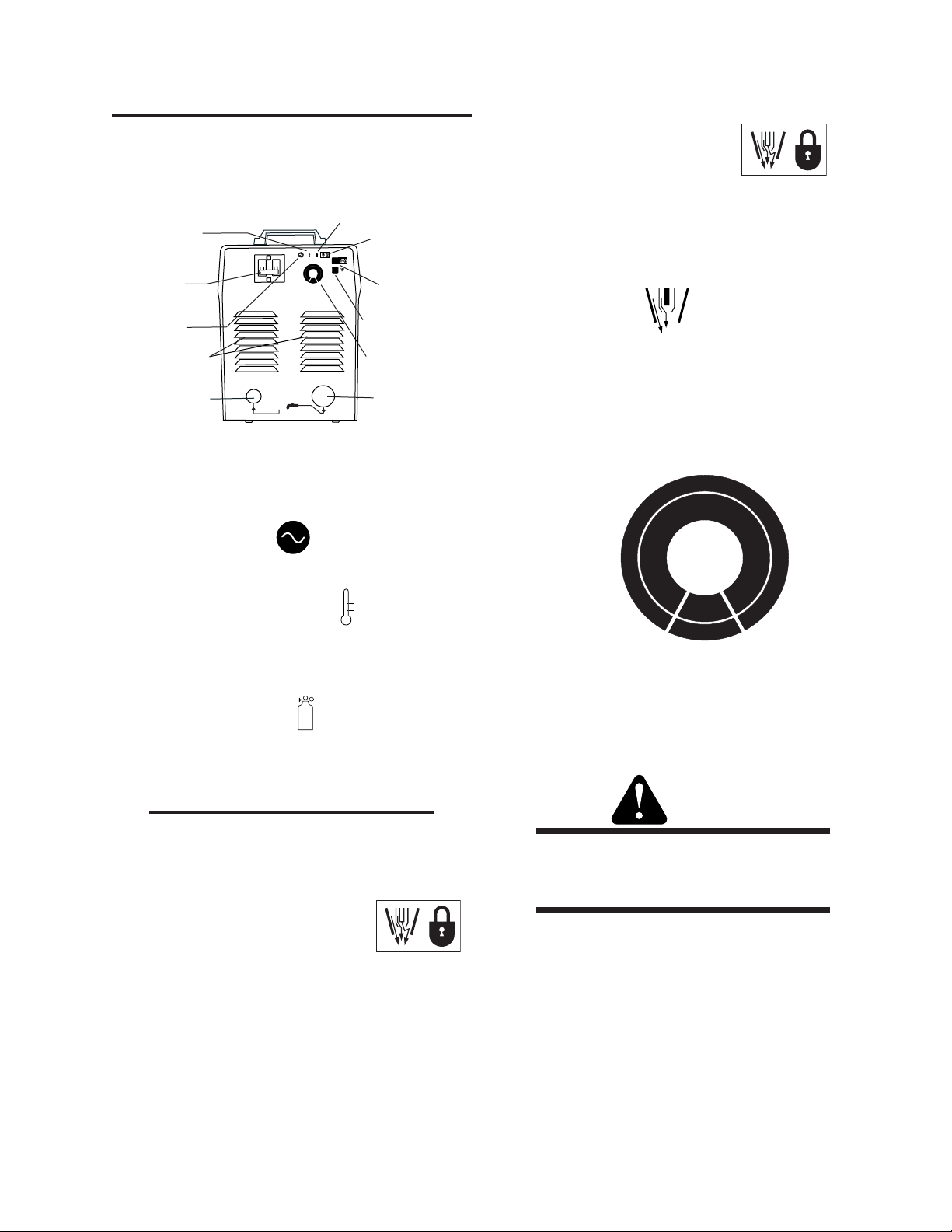
4.01 Front Control Panel
Overheating
Indicator
I
17
16
14
15
12
"On / Off"
20C
14
13
10
12
8
11
115VAC
10
O
230VAC
Switch
AC Power
Indicator
Air V ents
Work Lead
Connection
Art # A-04714
A. INDICATOR LAMP
• Power Indicator - Lights when primary
power switch is turned on.
• TEMPERA TURE Indicator - Indicator is normally OFF . Indicator is ON when internal tem-
perature exceeds normal limits. Shut unit OFF;
let the unit cool before continuing operation.
18
19
20
16
21
22
18
23
24
20
25
A
Torch Switch
Latch Indicato
Torch Switc
Latch Butto
Air Set
Button
Current
Control Knob
Torch
Connection
• Torch Switch Latch Button - For
continuous cutting performance. Depress this
button ( turn “On” ) while cutting with the torch.
Release the torch trigger and the torch will continue to cut without depressing the torch trigger.
• Air Set Button - To check for air flow and
to cool down heated torch.
C. MAIN CURRENT CONTROL KNOB
T o adjust cutting current. T urning clockwise increases the cutting current and counter clockwise decreases the cutting current.
18
17
14
19
16
20
20
25
18
21
22
23
24
13
14
12
15
11
10
16
12
10
8
115VAC
230VAC
D. PRIMARY POWER SWITCH, ON / OFF
• Air Error Indicator - This indicator lights
The power switch is located on the front panel.
Placing the primary power switch to the “ON”
and is accompanied by an intermittent audible
position energizes the power source.
tone when there is not enough air pressure to
operate the power supply.
NOTE
W ARNING
It is possible to have enough air pressure to operate the power supply but not enough air flow
to operate the torch.
When the power source is overloaded, the switch
turns to the OFF position automatically. DO
NOT TURN ON BY FORCE.
• Torch Switch Latch Indicator -
This indicator lights when the Torch Switch
Latch Button has been pressed for continuous
cutting.
Operation 4-1 Manual 0-4687
Page 16

4.02 Preparations For Operating
A
Make a clean work cable
W
A
Art # A-04389
S
8"
D. Torch Operation
At the start of each operating session:
W ARNING
Disconnect primary power at the source before
assembling or disassembling power supply, torch
parts, or torch and leads assemblies.
A. Torch Pa rts Selection
Check the torch for proper assembly and appropriate torch parts. The torch parts must correspond
with the type of operation, and with the amperage
output of this Power Supply (25 amps maximum).
Use only genuine manufacturer’s parts with this
torch.
Electrode, No. 9-6542
Gas Distributor,
No. 9-6507
• Wear gloves and protective goggles.
• Do not place bare hand on work piece.
1. For drag cutting, keep the torch in contact with
the workpiece.
2. For standoff cutting, hold the torch 1/8 - 3/8
in (3-9 mm) from the workpiece as shown below.
Torch
hield Cup
Standoff
Distance 1/8" - 3/
Torch Head Assembly
Tip, No. 9-6504
rt # A-04654
Shield Cup, No. 9-6003
B. Torch Connection
Check that the torch is properly connected.
C. Connect Work Cable
connection to the workpiece or cutting table
ork Cable
nd Clamp
A-00024
3. With the torch in starting position, press and
hold the T orch Trigger. After an initial two second pre-flow, the pilot arc will come on and
remain on until the cutting arc starts.
4. Once on, the main arc remains on as long as
the T orch Trigger is held down, unless the torch
is withdrawn from the work or torch motion is
too slow.
5. To shut off the torch simply release the Torch
T rigger . When the trigger is released a gas postflow will occur. If the Torch Trigger is pushed
during the post-flow , the cutting arc will restart
immediately when the torch is brought within
range of the workpiece.
Operation 4-2 Manual 0-4687
Page 17

E. Typical Cutting Speeds
Cutting speeds vary according to torch output, the type of material being cut, and operator skill. Speeds
shown are typical for this cutting system using air plasma to cut mild steel, with output current at the
highest setting and torch held at the indicated standoff height.
Unit Standoff
C-20C Drag Only (10GA) 0. 135" (3mm ) 42.7 1067 34.1 853
C-20C Drag Only (7GA) 0. 179" (4. 5mm ) 26.2 655 21.0 524
C-20C Drag Only 1/4" (6mm ) 16.0 401 12. 8 321
Material
Thickness
Max im um Travel S peed
Inch e s per
minute
Milimeters
per minute
Rec om mended Travel S p eed
Inch e s per
minute
Mi l imet ers per
NOTE:
Drag or Drag mode refers to the torch tip being in contact with the work piece at all times.
minute
Operation 4-3 Manual 0-4687
Page 18

This Page Left Blank
Operation 4-4 Manual 0-4687
Page 19

SECTION 5:
New Electrode
A
SERVICE
C. No air flow at torch when air check switch is turned on.
1. Internal connection is disconnected or loose.
a. Check all air line connections and fittings.
5.01 Basic Troubleshooting Guide
W ARNING
There are extremely dangerous voltage and power
levels present inside this unit. Do not attempt to
diagnose or repair unless you have had training in
power electronics measurement and troubleshooting techniques.
A. Basic Troubleshooting, Over view
This guide covers basic troubleshooting. It is helpful for
solving many of the common problems that can arise with
this system. If major complex subassemblies are faulty,
the unit must be returned to an authorized service center
for repair .
Follow all instructions as listed and complete each section in the order presented.
B. Common Symptoms
A. Primary power switch is ON, but power indicator
doesn’t light.
1. Improper electrical connection.
2. Internal air supply / compressor not working.
a. Return to an authorized service center for re-
pair .
3. Control PCB faulty.
a. Return to an authorized service center for re-
pair .
D . T orch will not pilot when torch switch is activated.
1. Gas pressure too high or too low.
a. There is no adjustment. Return to authorized
service center for repair .
2. Tor ch tip, start cartridge, or electrode missing.
a. Turn off power supply. Remove shield cup. In-
stall missing parts.
3. Worn or faulty torch parts
a. Inspect torch consumable parts. Replace if neces-
sary.
E. Cut performance is diminished.
1. Worn torch parts.
a. Check current setting. Check the Electrode and Tip
for excess wear .
a. Check the input cable line & connection.
b. Check that the input power :is turned on.
c. Check the input power fuse.
2. System was overloaded.
a. Turn Primary Power Switch Off and then On
again.
3. Switch may be faulty.
a. Return to an authorized service center for re-
pair .
B. Primary power switch is on, but the cooling fan
does not work.
1. No power / incorrect power to fan or failed fan.
a. Return to an authorized service center for re-
pair .
rt # A-03026
A-00323
Worn Electrode
Good Tip
Worn Tip
Manual 0-4687 5- 1 SERVICE
Page 20

2. Poor Work Lead connection.
Make a clean work cable
W
A
Art # A-04389
a. Check the connection of the Work Lead to the
work piece.
connection to the workpiece or cutting table
ork Cable
nd Clamp
3. Current sensor or PWM PCB faulty.
a. Return to an authorized service center for re-
pair .
F . Air flows continuously and torch switch latch
button doesn't work properly .
1. Tor ch Switch Latch button on front panel faulty .
a. Return to an authorized service center for re-
pair .
2. Control PCB faulty.
a. Return to an authorized service center for re-
pair .
SERVICE 5-2 Manual 0-4687
Page 21

Appendix 1: Operating Sequence, Block Diagram
d
Primary Input Power "On" or Plugged in
Power Supply On/Off Switch "On"
Red Air Indicator
Release Torch Switch
Pilot Arc Ignition (3-5 seconds)
Pilot Arc goes out
Green Power Indicator "On" and Fan is Running
Air Set Switch "On"
Compressor Starts and Air Flows at Torch. Turn Air Set Switch "Off"
Check Torch parts
Air Flow at Torch Stops
Torch Switch "On"
Torch Tip to Work within 3-5 seconds of Pilot Arc start
Start Cutting Operation
alignment. PIP switches
need to be repaired by a
Qualified T echnician
Release Torch Switch
More air flow is required
for Torch to Pilot than to
run the power supply.
Compressor not functioning
properly need to be repaire
by a Qualified Technician
No Pilot Arc
NO
Art # A-04694
YES
Post Flow of Air, Approximately 15 Seconds Then Stops
Note: The Torch will be very hot! Do not set on or near flammable materials!
Power Supply On/Off Switch "Off"
Green Power Indicator "Off" and Fan Stops
Primary Input Power Switch "Off" or Unplugged
Cutting Done ?
Torch Switch "Off"
Manual 0-4687 A-1 APPENDIX
Page 22

Appendix 2: Torch Connection
A
T
S
rt # A-04695
DETAIL
Disconnect power and air. Lay unit
on its side. Remove two screws and
access plate.
Power Supply
Adapter Connections
Negative / Plasma Lead
Pilot
o Power
upply Adapter
Negative / Plasma Lead
Pilot
Black
Orange
Green
White
Pilot
Torch Leads
PIP
Switch
Torch
Switch
Torch Head
APPENDIX A-2 Manual 0-4687
Page 23

Art # A-04700
Work
Piece
Appendix 3: System Schematic
Pilot
Torch
Current Sensor
Main T ransf ormer
IGBT
IGBT
Pilot
Relay
Conduit Coil
Reactor
H/V Board
Control Board
Torch
Filter
Hold
Panel Board
Air
Check
Hold
Air
Temp
Main
Error
Error
Power
Air Plazma 20C
Diode
Pressure
Sensor
Filter & Input
Selector
Compressor
Art # A-04700
Input AC
115/230V
1PH
Compressor Input
Fan
Selector
Manual 0-4687 A-3 APPENDIX
Page 24

This Page Left Blank
APPENDIX A-4 Manual 0-4687
Page 25

GLOBAL CUSTOMER SERVICE CONTACT INFORMATION
Thermadyne USA
2800 Airport Road
Denton, Tx 76207 USA
Telephone: (940) 566-2000
800-426-1888
Fax: 800-535-0557
Email: sales@thermalarc.com
Thermadyne Canada
2070 Wyecroft Road
Oakville, Ontario
Canada, L6L5V6
Telephone: (905)-827-1111
Fax: 905-827-3648
Thermadyne Europe
Europe Building
Chorley North Industrial Park
Chorley, Lancashire
England, PR6 7Bx
Telephone: 44-1257-261755
Fax: 44-1257-224800
Thermadyne Asia Sdn Bhd
Lot 151, Jalan Industri 3/5A
Rawang Integrated Industrial Park - Jln Batu Arang
48000 Rawang Selangor Darul Ehsan
West Malaysia
Telephone: 603+ 6092 2988
Fax : 603+ 6092 1085
Cigweld, Australia
71 Gower Street
Preston, Victoria
Australia, 3072
Telephone: 61-3-9474-7400
Fax: 61-3-9474-7510
Thermadyne Italy
OCIM, S.r.L.
Via Benaco, 3
20098 S. Giuliano
Milan, Italy
Tel: (39) 02-98 80320
Fax: (39) 02-98 281773
Thermadyne, China
RM 102A
685 Ding Xi Rd
Chang Ning District
Shanghai, PR, 200052
Telephone: 86-21-69171135
Fax: 86-21-69171139
Thermadyne International
2070 Wyecroft Road
Oakville, Ontario
Canada, L6L5V6
Telephone: (905)-827-9777
Fax: 905-827-9797
Page 26

Corporate Headquarters
16052 Swingley Ridge Road
Suite 300
St. Louis, MO 63017
Telephone: 636-728-3000
Email: TDCSales@Thermadyne.com
www.thermadyne.com
 Loading...