

Page 1

Manual 0-4960
82 Benning Street, West Lebanon, NH 03784 USA
(603) 298-5711 • www.thermal-dynamics.com
for 9-9430 and 9-9489
Installation Instructions
Unpacking
Retainer Ring Replacement
The product is packaged and protected to prevent damage during shipping. Inspect for possible shipping damage. If
damage is evident, contact your distributor and/or shipping company before proceeding with installation.
Contents
• Snap Ring Pliers
• Installation Instructions
Applications
This product is for use only with Thermal Dynamics XT-300 or XT-301 Torch Cartridge Retaining Rings 9-9430 and
9-9489.
© 2006 by Thermal Dynamics Corp., Printed in USA
December 12, 2006 1 Manual 0-4960 Rev. AA.01
Page 2
W ARNINGS
Disconnect primary power at the source before starting the procedure.
1. Once you have disconnected power, remove the torch cartridge and dissasemble to the point shown in the
following illustration.
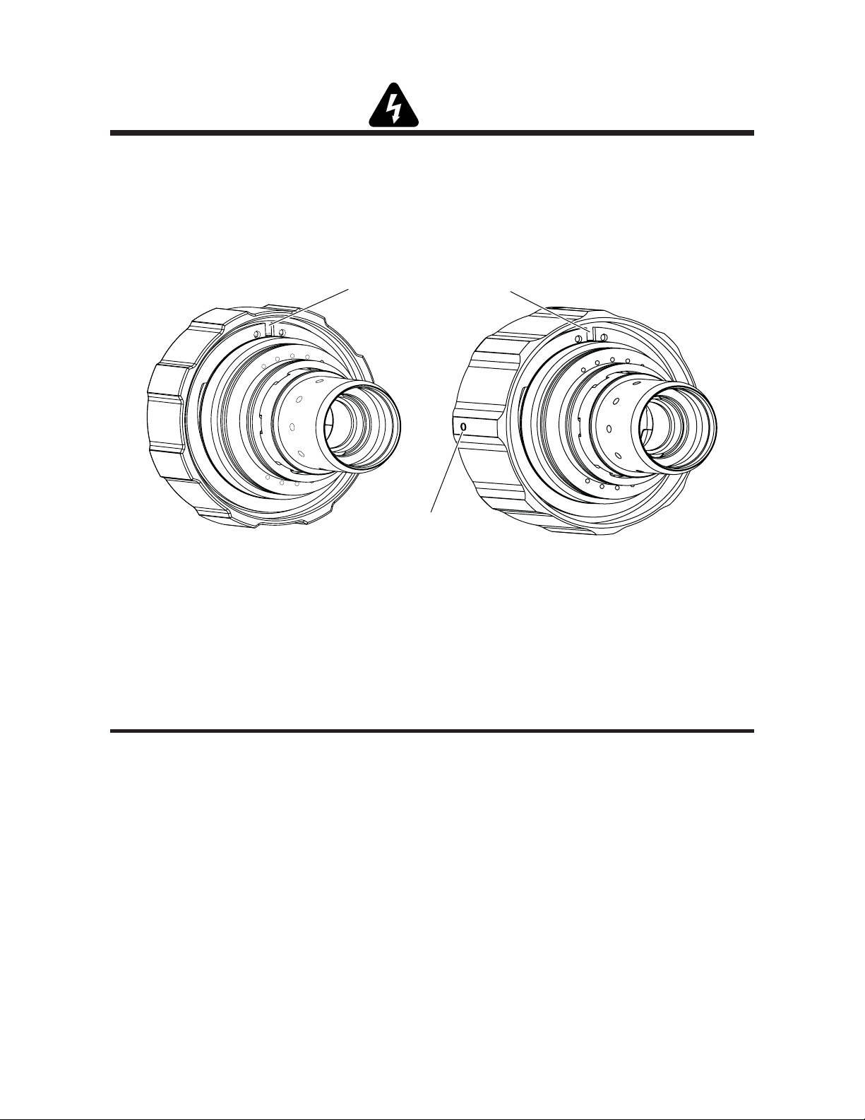
Snap Ring gap 1/8” (3mm) or less
Art # A-07634
Alignment Pin
Threaded Style Retaining Ring
Ring Only 9-9430
SpeedLok™ Retaining Ring
Ring Only 9-9489
2. Insert the points of the pliers into the holes of the snap ring. Apply enough pressure to spread the snap ring so
it can be removed.
3. Remove the Retaining Ring.
4. Install the new retaining ring by reversing steps 1-3 above.
NOTE
If you are installing a threaded ring, make sure the threads go on first. If you are installing the SpeedLok™ style with
two pins instead of threads, make sure the pins go on first.
5. Verify that the snap ring is properly seated in the groove. To do this, check the snap ring gap and movement of
the retaining ring. The gap should not be more than 1/8" (3mm) and the retaining ring should turn freely on the
cartridge. If not, then use the tips of the pliers or a flat blade screwdriver to press downward on the ring until it
snaps into place and both items are correct.
6. This completes the instructions for replacing the cartridge retaining ring.
NOTE
Every effort has been made to provide complete and accurate information in this manual. However, the
publisher does not assume and hereby disclaims any liability to any party for any loss or damage caused by
errors or omissions in this manual, whether such errors result from negligence, accident or any other cause.
December 12, 2006 2 Manual 0-4960 Rev. AA.01
 Loading...