

Truma DuoC Series, DuoComfort, DuoControl, DuoControl CS Operating Instructions & Installation Instructions
Fernanzeige DuoC
Gebrauchsanweisung Seite 2
Einbauanweisung Seite 4
Im Fahrzeug mitzuführen!
Operating instructions Page 8
Installation instructions Page 9
To be kept in the vehicle!
Mode d‘emploi Page 13
Instructions de montage Page 14
À garder dans le véhicule !
Istruzioni per l‘uso Pagina 18
Istruzioni di montaggio Pagina 19
Da tenere nel veicolo!
Gebruiksaanwijzing Pagina 23
Inbouwhandleiding Pagina 24
Im vertuig meenemen!
Brugsanvisning Side 28
Monteringsanvisning Side 29
Skal medbringes i køretøjet!
Instrucciones de uso Página 33
Instrucciones de montaje Página 34
¡Llévalas en el vehículo!
Page 40
A
DuoComfort
5
4
1
D
u
o
6
C
o
m
fort
2
9
DuoControl CS
5
4
1
6
2
9
DuoControl
50 cm
5
4
1
6
2
9
50 cm
10
18
B
-
12 V
50 cm
55 mm
14
19
13
+
15
12
11
17
16
17

Fernanzeige DuoC
Verwendungszweck
Die Truma Fernanzeige zeigt
den Betriebsstatus (Normaloder Reservebetrieb) zur
standard mäßi gen Anzeige
im Flaschenkasten auch im
Fahrzeug inneren an.
Zusätzlich beinhaltet die Fernanzeige die Reglerbeheizung EisEx
zum Beheizen der UmschaltRegleranlage im Winter.
Gebrauchsanweisung
DuoC
f
d
e
a = Ein (Sommerbetrieb)
b = Aus
c = Ein und Heizen
(Winterbetrieb)
d = Rote LED
e = Grüne LED
f = Gelbe LED
EisEx (Winterbetrieb)
Inbetriebnahme
Sommerbetrieb
c
b
a
Schalter nach unten (a).
Die Leuchtdioden zeigen den
Zustand der Betriebsflasche an:
voll = grüne LED leuchtet,
leer = rote LED leuchtet.
Winterbetrieb
Schalter nach oben (c). Zusätzlich zur Status-Anzeige der
Betriebsflasche wird das Umschaltventil bzw. die UmschaltRegleranlage (Bild A: 1) beheizt
und dieses mit der gelben LED
angezeigt.
3
Technische Daten
Versorgungsspannung
12 V
Stromaufnahme
Sommerbetrieb: 1,5 mA
Winterbetrieb mit EisEx: 160 mA
Die Fernanzeige erfüllt die
Richtlinie zur Funkentstörung von Kraftfahrzeugmotoren 72/245/EWG mit
Ergänzungen und trägt die
Typengenehmigungsnummer:
e1 03 4352
4
Einbauanweisung
Einbau und Reparatur der
Fernanzeige dürfen nur vom
Fachmann durchgeführt
werden.
Bei Verwendung von fahrzeugbzw. herstellerspezifischen Bedienteilen muss der elektrische
Anschluss gemäß der Truma
Schnittstellenbeschreibung
(Art.-Nr. 50020-56600) erfolgen.
Der elektrische An-
schluss bzw. die
Verbindung zu einer Kabelverlängerung darf nicht im
Flaschenkasten erfolgen!
Für Flaschenkasten-Durchführung (9) Gummitülle oder Karosseriedichtmittel verwenden.
Durchführung mindes tens 50 cm
über dem Boden des Flaschenkastens vorsehen.
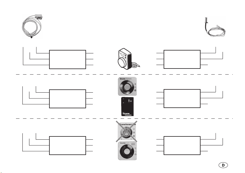
Austausch Fernanzeige
DuoC für ältere
Fernanzeigeversionen
Beim Austausch der Truma
Fernanzeige DuoC für
Vorgängerversionen einer
Fernanzeige, kann das Verbindungskabel zwischen Regelanlage und Bedienteil gemäß den
Anschlussplänen weiter verwendet werden (siehe Seite 5).
PK
PK
PK
YE
YE
YE
BN
BN
BN
BK = Black YE = Yellow GY = Grey
BN = Brown GN = Green WH = White
RD = Red BU = Blue PK = Pink
Duomatic L
Duomatic L
Triomatic
Triomatic
Duomatic L plus
Duomatic L plus
BU
BK
BK
BK/RD
BK/WH
BN
YE
PK
Bedienteil
BU
BN
BK
BK
WH
GN
GY
Duomatic L
Duomatic L
Triomatic
Triomatic
Duomatic L plus
Duomatic L plus
EisExFernanzeige
WH
GN
WH
GN
WH
GN
5

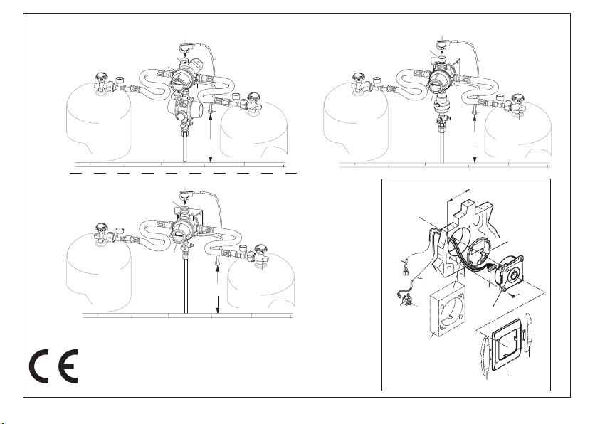
Montage des
Fernanzeige-Gebers
Bild A
Sechskant auf der Sichtanzeige
mit Hilfe des Gebers (5) abdrehen und entfernen. Eventuell
verbleibende Späne restlos
entfernen.
Geber (5) auf die Sichtanzeige (4)
aufstecken.
Das 3-polige Anschlusska bel (6)
aus dem Flaschenkasten führen
und mit dem schwarzen Stecker
des Bedienteilkabels verbinden.
6
Montage EisEx
Wegen Verbrennungsge-
fahr EisEx nicht im ausgebauten Zustand betreiben!
Sackloch am Umschaltventil
bzw. an der Umschalt-Regleranlage auf Verschmutzung überprüfen und gegebenenfalls reinigen. Heizpatrone in das Sackloch
einstecken und mit der beiliegenden Schraube befestigen.
Das 2-polige Anschlusskabel (2)
aus dem Flaschenkasten führen
und mit dem weißen Stecker des
Bedienteilkabels verbinden. Das
Kabel ist mit Kabelbindern oder
Ähnlichem am Regleranschlussschlauch bzw. Gasrohr gegen
Durchscheuern zu sichern.
Elektrischer Anschluss
1. Bild B
Platz für das Bedienteil (12) an
gut sichtbarer Stelle vorsehen.
Länge der Anschlusskabel 6 m.
Bei Bedarf ist ein Verlängerungskabel 5 m lieferbar (Art.-Nr.
34300-01).
Ist eine Unterputzmontage
des Bedienteils nicht möglich, liefert Truma auf Wunsch einen Aufputzrahmen (11 – Art.-Nr.
40000-52600) als Zubehör.
2. Loch Ø 55 mm bohren. Den
10-poligen Stecker des Bedienteilkabels (13) von hinten durch
die Bohrung führen und am Bedienteil anstecken.
3. Bild B
Hintere Abdeckkappe (14) als
Zugentlastung aufsetzen und
Bedienteil (12) mit 4 Schrauben
(15) befestigen. An schließend
Abdeckrahmen (16) aufstecken.

Zum optischen Abschluss
der Abdeckrahmen (16)
liefert Truma Seitenteile (17) in 8
verschiedenen Farben. Bitte fragen Sie Ihren Händler.
4. Zuleitung 12 V (19) mit beiliegender Sicherung 1 A (18)
absichern. (Sicherung bei industrieller Großverpackung nicht im
Lieferumfang.)
Rot = Plus
Blau = Minus
Bei direktem Anschluss an die
Batterie ist die Plus- und Minusleitung abzusichern.
Falls erforderlich, kann die Spannungsversorgung mit einem Kabel
2 x 0,75 mm² verlängert werden.
Bei Verwendung von Netz-
teilen ist zu beachten, dass
die Ausgangsspannung zwischen
11 V und 15 V liegt.
Die Fernanzeige kann über den
Truma Trafostecker (Art.-Nr.
53110-01) auch mit 230 V betrieben werden. Der Trafostecker
liefert 12 V Wechselstrom mit
geringer Leistung. Die zwei
Kabel am Trafostecker können
beliebig angeklemmt werden.
Über den Trafostecker kann nur
die Fernanzeige betrieben werden (ein An schluss von weiteren
12 V-Geräten ist nicht möglich).
Funktionsprüfung
Nach dem Einbau muss die
Funktion der Fernanzeige gemäß
der Gebrauchsanweisung
geprüft werden.
Die Gebrauchsanweisung ist
dem Betreiber auszuhändigen.
7
Remote indicator DuoC
Intended use
The Truma remote indicator
shows the operating status
(normal or reserve operation)
inside the vehicle, in addition
to the standard display in the
cylinder box.
The remote indicator also includes the EisEx regulator heater
for heating the changeover regulator system during the winter
months.
8
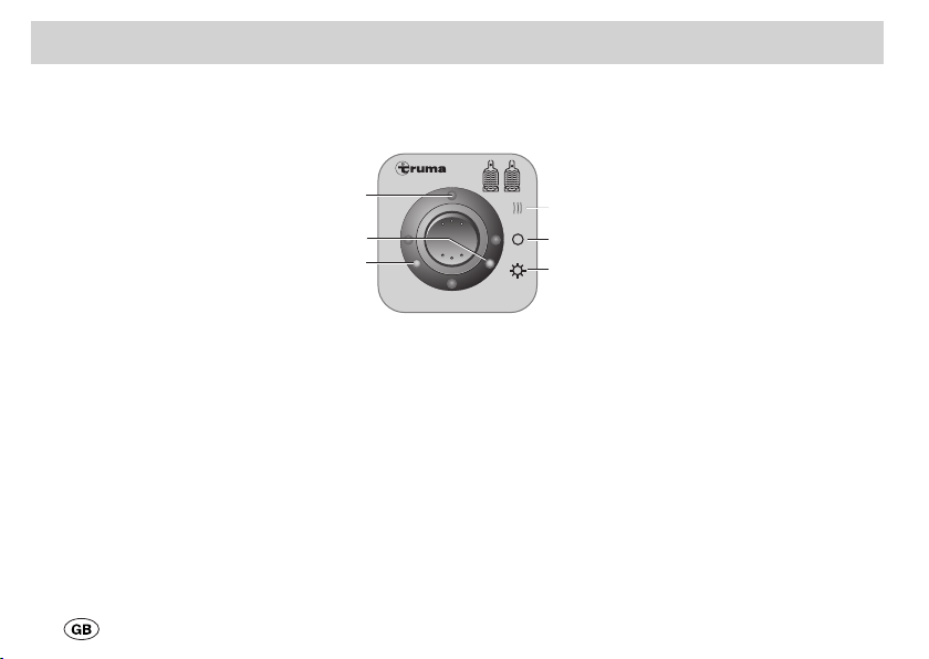
Operating instructions
DuoC
f
d
e
a = On (summer operation)
b = Off
c = On and heat
(winter operation)
d = red LED
e = green LED
f = yellow LED
EisEx (winter operation)
c
b
a
Taking into operation
Summer operation
Move the switch down to (a).
The LEDs indicate the condition
of the operating cylinder:
full = green LED illuminates,
empty = red LED illuminates.
Winter operation
Switch up (c). As well as indicating the status of the used
cylinder, the changeover valve
or changeover regulator system
(fig. A: 1) is heated, which is
indicated by the yellow LED.
Technical data
Supply voltage
12 V
Current input
summer operation: 1,5 mA
winter operation with
defroster (EisEx): 160 mA
The Remote indicator complies
with the vehicle engine interference suppression directive
72/245/EEC with supplements
and bears type approval number:
e1 03 4352
Installation instructions
Only an expert technician
may install and repair the
remote indicator.
When using specific vehicle or
manufacturer control panels, the
electrical connection must be
in accordance with the Truma
interface description (part no.
50020-56600).
The electrical connec-
tion or the connection
to a cable extension must not
be effected in the cylinder
container!
For passing cables through a
cylinder container (9), use rubber
grommets or bodywork sealing
material. Establish the cable run
at least 50 cm above the base of
the cylinder container.
Replacing earlier remote indicator versions with the DuoC
remote indicator.
When earlier versions of a remote indicator are replaced with
the Truma DuoC remote indicator, the connecting cable between the regulation system and
the control panel can be re-used
in accordance with the wiring
diagrams (see page 10).
9

10
PK
PK
PK
YE
YE
YE
BN
BN
BN
BK = Black YE = Yellow GY = Grey
BN = Brown GN = Green WH = White
RD = Red BU = Blue PK = Pink
Duomatic L
Duomatic L
Triomatic
Triomatic
Duomatic L plus
Duomatic L plus
BU
BK
BK
BK/RD
BK/WH
BN
YE
PK
Control panel
BU
BN
BK
BK
WH
GN
GY
Duomatic L
Duomatic L
Triomatic
Triomatic
Duomatic L plus
Duomatic L plus
EisExRemote indicator
WH
GN
WH
GN
WH
GN

Assembling the remote
indicator’s transmitter
Fig. A
Use the transmitter (5) to turn
off and remove the hexagon on
the visible indicator. Completely
remove any chips that may be
left behind.
Place the transmitter (5) onto the
visible indicator (4).
Lead the three-pole connection
cable (6) from the cylinder box
and connect it to the black plug
on the control panel cable.
Assembling EisEx
Due to the danger of fire,
never operate EisEx in the
uninstalled condition!
Check pocket hole at changeover valve or changeover regulator system for soiling and clean
if necessary. Insert the heating
cartridge into the pocket hole
and fasten it in place with the
included screw.
Lead the two-pole connection
cable (2) from the cylinder box
and connect it to the white plug
on the control panel cable. Use
cable binders or something
similar to secure the cable onto
the regulator connection hose or
the gas pipe, thereby securing it
from sliding abrasion.
Electrical connection
1. Fig. B
Provide space for the control
panel (12) at an easily visible
location. Length of the connection cable 6 m. If required, a 5 m
extension cable is available
(part no. 34300-01).
If it is not possible to install
the control panel flush
with the surface, Truma can provide a surface-mounting frame
(11) on request, as a accessory
(part no. 40000-52600).
2. Drill two holes of 55 mm
diameter. Lead the ten-pole plug
on the control panel cable (13)
through the hole from the back
and connect it to the control
panel.
11

3. Fig. B
Fit the rear cover cap (14) as a
stress-relieving device, then secure the control panel (12) with
4 screws (15) and fit the cover
frame (16).
Truma offers side parts (17)
in eight different colors for
finishing the cover frames (16)
in a visually pleasing way. Please
ask your dealer.
4. Protect 12 V power supply
line (19) using provided 1 A fuse
(18). (Fuses not included in industrial bulk packaging.)
Red = plus
Blue = minus
When connecting directly to the
battery, always fuse the positive
and negative lead.
12
If necessary, the voltage supply
can be lengthened with an extension cord of 2 x 0.75 mm².
When using power supply
units, make sure that the
output voltage is between 11 V
and 15 V.
With the Truma transformer
connector (part no. 53110-01)
the remote indicator can also be
operated with 230 V. The transformer connector supplies
a 12 V alternating current with
low power. The two cables on
the transformer connector can
be connected in any order.
Only the remote indicator can be
powered over the transformer
plug (it is not possible to connect
additional 12 V devices).
Function check
The operation of the remote
indicator must be tested after
installation, as described in the
operating instructions.
The operating instructions are to
be handed over to the user.
 Loading...