


Trumatic
S 3002 P
S3002
S5002
30050-93100 · 03 · 12/2003 · 20’ B+W · ©
Bruksoch monteringsanvisningar på svenska kan rekvireras från tillverkaren Truma eller från Truma-Service i Sverige.
Käyttöja asennusohjeita on saatavissa
Truma-valmistajalta tai Truma-huollosta.
Bruksanvisningen og monteringsveiledningen på ditt språk kan fås hos produsenten Truma eller hos Truma-Service i ditt land.
Τις δηγίες ρήσης και τ π θέτησης στη µητρική σας γλώσσα µπ ρείτε να τις λά ετε απ τ ν κατασκευαστή Truma ή απ τ σέρ ις Truma στη ώρα σας.
Instruções de utilizaçaõ e instruções de montagem podem ser solicitadas junto ao fabricante Truma ou da assistência técnica da Truma no seu país.
Návod k použití a montáži ve svém jazyce obdržíte na požádání u firmy Truma nebo u jejího servisního zástupce ve vaší zemi.
Návod na použitie a montážny návod vo Vašej krajinskej reči si môžete vyžiadať u výrobcu Truma alebo v servise Truma vo Vašej krajine.
A magyar nyelvü használati és szerelési utasítást a gyártónál a Truma cégnél vagy a Truma magyarországi képviseleténél lehet beszerezni.
Instrukcję obsługi i montażu w ojczystym języku mogą Państwo dostać u producenta (Truma) lub w serwisie Trumy w swoim kraju.
Navodila za uporabo in vgradnjo v Vašem jeziku lahko zahtevate pri izdelovalcu Truma ali servisu Truma v Vaši državi.
Einbauanweisung |
Seite 3 |
Installation instructions |
Page 6 |
Instructions de montage |
Page 9 |
Istruzioni di montaggio |
Pagina 12 |
Inbouwhandleiding |
Pagina 15 |
Monteringsanvisning |
Side 18 |
Instrucciones de montaje |
Página 21 |
Truma Gerätetechnik |
Service |
|
||
GmbH & Co. KG |
Telefon |
+49 (0)89 4617-142 |
e-mail: info@truma.com |
|
Postfach |
1252 |
|||
D-85637 |
Putzbrunn |
Telefax |
+49 (0)89 4617-159 |
www.truma.com |

A |
S 3002 (P) |
|
A |
S 5002 |
|
|
|
|
|
B |
2 cm2 |
ca. 5 - 10 cm |
D S 3002 (P) |
C |
S 3002 (P) |
|
C |
S 5002 |
|
|
|
|
|
D S 5002 |
|
E S 3002 (P) |
|
E S 5002 |
|
|
|
|
|
F |
|
G |
S 3002 (P) |
|
G |
S 5002 |
|
|
|
|
|
|
|
|
|
|
|
|
|
|

Trumatic S 3002 P
Trumatic S 3002
Trumatic S 5002
Flüssiggasheizung
Der Einbau in das Innere von Kraftomnibussen und in Fahrzeuge zum Transport gefährlicher Güter ist nicht zulässig.
Bei Einbau in Sonderfahrzeuge müssen die dafür geltenden Vorschriften berücksichtigt werden.
Einbauanweisung
Einbau und Reparatur der Heizung darf nur vom Fachmann durchgeführt werden. Vor Beginn der Arbeiten Einbauanweisung sorgfältig durchlesen und befolgen!
Verwendungszweck
Diese Heizung wurde für den Einbau in Caravans, Reisemobile und sonstige Anhänger konstruiert. Der Einbau in Boote ist nicht zulässig. Andere Anwendungen sind nach Rücksprache mit Truma möglich.
Zulassung
Konformitätserklärung:
Die Trumatic S ist durch den DVGW baumustergeprüft und erfüllt die EG-Gasgeräte- Richtlinie (90/396/EWG) sowie die mitgeltenden EGRichtlinien. Für EU-Länder liegt die CE-Produkt-Ident- Nummer vor:
S 3002 (P): CE-0085AP0325 S 5002: CE-0085AP0326
Das Heizgerät ist für den Einbau in von Personen benutzten Räumen (in Kraftfahrzeugen) und unter Berücksichtigung nationaler Bestimmungen auch während der Fahrt zugelassen.
Hinweis für den Einbau in Deutschland: Diese Heizung darf nicht in Kraftfahrzeuge
(z.B. Reisemobile) eingebaut werden, die für die Zulassung in Deutschland bestimmt sind. Für Kraftfahrzeuge bietet Truma die vom Kraftfahrt-Bundesamt typgeprüften Heizungen Trumatic S 3002 K, Trumatic C oder Trumatic E an.
Für andere Länder sind beim Einbau der Heizung in Reisemobile besondere Hinweise zu beachten (siehe „Besondere Einbauhinweise“).
Vorschriften
Jede Veränderung am Gerät (einschließlich Abgasführung und Kamin) oder die Verwendung von Ersatzteilen und funktionswichtigen Zubehörteilen, die keine Original- Truma-Teile sind, sowie das Nichteinhalten der Einbauund Gebrauchsanweisung führt zum Erlöschen der Garantie sowie zum Ausschluss von Haftungsansprüchen. Außerdem erlischt die Betriebserlaubnis des Gerätes und dadurch in manchen Ländern auch die Betriebserlaubnis des Fahrzeuges.
Das Jahr der ersten Inbetriebnahme muss auf dem Fabrikschild angekreuzt werden.
Der Einbau in Fahrzeuge muss den technischen und administrativen Bestimmungen des jeweiligen Verwendungslandes entsprechen (z.B. EN 1949). Nationale Vorschriften und Regelungen (in Deutschland z.B. das DVGWArbeitsblatt G 607) müssen beachtet werden.
In anderen Ländern sind die jeweils gültigen Vorschriften zu beachten.
Nähere Angaben zu den Vorschriften in den entsprechenden Bestimmungsländern können über unsere Aus- lands-Vertretungen (siehe Gebrauchsanweisung) angefordert werden.
Die Verbrennungsluft darf nicht aus dem Fahrzeuginnenraum entnommen werden. Es muss immer die Verbrennungsluft von außen zugeführt werden.
Platzwahl
1.Das Gerät und seine Abgasführung ist grundsätzlich so einzubauen, dass es für Servicearbeiten jederzeit gut zugänglich ist und leicht ausund eingebaut werden kann.
2.Die Heizung wird in der Regel im Kleiderschrank des Fahrzeuges eingebaut.
Einbauausschnitt:
S 3002 (P): 480 x 480 mm S 5002: 510 mm breit, 522 mm hoch.
Für eine einwandfreie Funktion der Heizung ist es wichtig, dass Heizungssockel und Einbaukasten-Unterkante auf einer Ebene montiert sind, damit der Bedienungsgriff mit der Verkleidung bündig abschließt.
3. Anhand der Einbauschablone prüfen, ob der Bodenausschnitt
(S 3002 (P): 205 x 100 mm, S 5002: 235 x 230 mm) für die Verbrennungsluft-Ansau- gung rechts oder links unterhalb des Gerätes erfolgen soll (Bild A zeigt Rechtseinbau, Bild G Linkseinbau). Die Ver- brennungsluft-Ansaugung darf nicht im Spritzbereich der Räder liegen, evtl. Spritzschutz anbringen.
Unterhalb des Gerätes  dürfen sich keine wärmeempfindlichen Materialien befinden (Teppichboden aus-
schneiden). Bei PVC-Böden kann eine Verfärbung durch die Erwärmung des Heizungssockels auftreten.
Bild B: Wird die Heizung auf einen Sockel oder Ähnlichem montiert, muss zwingend die Ansaugverlängerung (Art.-Nr. 30030-04800, Länge 50 cm) verwendet werden.
Die Ansaugverlängerung muss frei im Luftstrrom ca. 5 bis 10 cm unter der tiefsten Stelle des Fahrzeuges herausragen (Länge bei Bedarf kürzen). Für Trumatic S 5002 sind 2 Ansaugverlängerungen erforderlich.
Der Sockel muss dicht gegenüber dem Fahrzeuginnenraum sein und wegen der Gefahr eines Zurückbrennens unter ungünstigen Windverhältnissen aus nicht brennbarem Material gefertigt oder innen mit Blech verkleidet werden. Zur Vermeidung der Ansammlung von unverbranntem Gas, muss der Sockel eine Entlüftung von min. 2 cm2 an tiefster Stelle haben oder nach unten offen sein.
4. Abgasleitungen und Kamine müssen so installiert sein, dass das Eindringen von Abgas in das Fahrzeuginnere nicht möglich ist.
Um eine gleichmäßige und rasche Warmluftverteilung sowie eine Absenkung der Oberflächentemperaturen am Heizgerät sicherzustellen, empfehlen wir den
Einbau einer TrumaventWarmluftanlage.
Auf Wunsch ist die Heizung Trumatic S 5002
auch mit einem speziellen Einbaukasten für zwei Trumavent-Gebläse lieferbar.
Vorarbeiten und Einbaukasten
1.Bodenschablone im Einbauausschnitt mit Reißnägeln befestigen, der Pfeil muss genau auf die Vorderkante des Ausschnittes zeigen
(R = Rechtseinbau, L = Linkseinbau).
2.Bodenausschnitt aussägen und die 5 Punkte für die Befestigungsschrauben vorstechen. Die Maße müssen genau eingehalten werden!
3.Bild A: Rahmenhälften (5) in den Bodenausschnitt einlegen, nach außen drücken und festschrauben (evtl. vorher durch Aufbiegen der Schenkel vorspannen, damit der Rahmen gut sitzt).
4.Bild D: Am EinbaukastenAußenteil die vorgestanzten Durchbrüche für das Abgasrohr ausbrechen (R = Rechtseinbau, L = Linkseinbau)! Bei geringer Einbautiefe kann bei der Heizung S 5002 das Abgasrohr auch seitlich durchgeführt werden (R1 oder L1).
Bei Einbau des Spezialrohres für Innen-Gasanschluss (siehe „Gasanschluss“) beide Durchführungen ausbrechen!
Falls ein TrumaventGebläse und/oder die
Elektro-Zusatzheizung TrumaUltraheat montiert wird, die entsprechend vorgestanzten Deckel (T) bzw. (U) entfernen und diese entsprechend der jeweils beiliegenden Einbauanweisung am Einbaukasten vormontieren.
5. Bild C: EinbaukastenAußenteil (1) und Innenteil (2) aufeinanderlegen und mit
5 Blechschrauben (19) befestigen.
Bei der Heizung S 5002  müssen die Schrauben 19a für Rechtseinbau und die
Schrauben 19b für Linkseinbau verwendet werden.
Wird kein Trumavent-Gebläse angebaut, die 3 Bestigungsschrauben (35) trotzdem fest eindrehen.
6. Den vormontierten Einbaukasten im Einbau-Ausschnitt mit 6 Schrauben (6) jeweils schräg nach außen verschrauben.
3

Heizungseinbau
Trumatic S 3002 P
1. Bild A: Heizgerät in den Bodenausschnitt stellen. Thermostatfühler mit Abschirmblech (7) in Schlitz (8) einstecken und bis zum hörbaren Einrasten unter die Befestigungslasche (9) schieben (Bild A zeigt Rechtseinbau, Bild G Linkseinbau).
Der Thermostatfühler  (7) muss immer vorne an der Heizung (Raumseite)
montiert sein. Thermostatfühler (7) und Kapillarrohr (10) dürfen auf keinen Fall am Wärmetauscher bzw. an der Heizungsverkleidung anliegen!
2.Bild C: Heizung an die hinteren Distanzwinkel (18) im Einbaukasten heranschieben.
3.Bild A: Heizung mit den 5 Schrauben (3) an den vorgestochenen Punkten in den Ecken und vorne mittig befestigen. Eventuell Bodenkonstruktion durch Leisten verstärken.
4.Bild A: Die Massefeder (30) aus der Transportsicherung herausdrücken, damit diese am Einbaukasten anliegt (sonst funktioniert die Zündung nicht).
5.Bild A: Druckstange mit Ösenfeder (11) in das Zündsicherungsventil (12) einstecken.
Zündkabel (38) auf der Seite der Druckstange in den
3 Haltelaschen (39) des Einbaukastens befestigen.
Trumatic S 3002
1. Bild A: Heizgerät in den Bodenausschnitt stellen. Thermostatfühler mit Abschirmblech (7) in Schlitz (8) einstecken und bis zum hörbaren Einrasten unter die Befestigungslasche (9) schieben (Bild A zeigt Rechtseinbau, Bild G Linkseinbau).
Der Thermostatfühler  (7) und Zündautomat (15) müssen sich immer vorne an der Heizung (Raumsei-
te) befinden. Thermostatfühler (7) und Kapillarrohr (10) dürfen auf keinen Fall am Wärmetauscher bzw. an der Heizungsverkleidung anliegen!
2. Bild C: Heizung an die hinteren Distanzwinkel (18) im Einbaukasten heranschieben.
4
3.Bild A: Zündautomat (15) aus der Halterung entnehmen. Heizung mit den
5 Schrauben (3) an den vorgestochenen Punkten in den Ecken und vorne mittig befestigen. Eventuell Bodenkonstruktion durch Leisten verstärken.
4.Am Zündautomat (15) den korrekten Sitz der Steckanschlüsse (13 + 14) überprüfen. Dann Zündautomat (15) bis zum Anschlag in die Laschen (16) einschieben
(Bild A zeigt Rechtseinbau, Bild G Linkseinbau).
5.Bild A: Druckstange mit Ösenfeder (11) in das Zündsicherungsventil (12) einstecken.
Trumatic S 5002
1. Bild A: Heizgerät in den Bodenausschnitt stellen. Thermostatfühler mit Abschirmblech (7) in Lasche (8) einstecken und mit Schraube
(9) befestigen (Bild A zeigt Rechtseinbau, Bild G Linkseinbau).
Thermostatfühler (7) und Zündautomat (15)
müssen sich immer vorne an der Heizung (Raumseite) befinden. Thermostatfühler (7) und Kapillarrohr (10) dürfen auf keinen Fall am Wärmetauscher bzw. an der Heizungsverkleidung anliegen!
2.Bild A: Zündautomat (15) aus der Halterung entnehmen. Heizung mit den
5 Schrauben (3) an den vorgestochenen Punkten in den Ecken und vorne mittig befestigen. Eventuell Bodenkonstruktion durch Leisten verstärken.
3.Am Zündautomat (15) den korrekten Sitz der Steckanschlüsse (13 + 14) überprüfen. Dann Zündautomat (15) bis zum Anschlag in die Laschen (16) einschieben
(Bild A zeigt Rechtseinbau, Bild G Linkseinbau).
4.Bild A: Druckstange mit Ösenfeder (11) in das Zündsicherungsventil (12) einstecken. Bedienungsgriff (55) auf die Druckstange (11) so aufstecken, dass der Pfeil zur „0“ Stellung (Heizungsmitte) zeigt.
Abgaskamin
Die Heizung ist nur mit Dachkamin zulässig. Dieser darf nur senkrecht oder mit maximal 15 Grad Neigung eingebaut werden!
Bild F: Dachkamin so platzieren, dass von der Heizung zum Kamin eine direkte, auf ganzer Länge steigende Rohrverlegung (min. 1,5 m, max. 3 m) möglich ist. Bei einer Rohrlänge von 1,5 m muss eine Mindesthöhe von 1 m erreicht sein. Die weitere Rohrverlegung zum Dachkamin muss nahezu senkrecht erfolgen.
Länge des Abgasrohres min. 1,5 m, max. 3 m!
Eine erhebliche Montage-Er- leichterung für das Biegen des Edelstahlrohres und das Aufziehen des O-Ringes bringt die Verwendung des Biege-Boys
(Art.-Nr. 30030-33000).
1. Abgasrohr an die Heizung anschließen:
Trumatic S 3002 (P)
Bild E: Öffnung von
Ø 60 mm in einem Mittelabstand von min. 55 mm zu seitlichen Wänden ausschneiden.
Trumatic S 5002
1. Bild E: Öffnung von
Ø 70 mm in einem Mittelabstand von min. 60 mm zu seitlichen Wänden ausschneiden.
2.Bild E: Bei doppelschaligen Dächern den Hohlraum mit Holz ausfüttern oder einen kreisförmig eingerollten Blechstreifen (20) von etwa
220mm Länge und 1 mm Stärke einschieben, um das Dach so zu versteifen, dass es beim Anziehen der Verschraubung nicht verformt wird und regendicht bleibt.
3.Bild E: Kamin von oben durch das Dach stecken und innen mit Schraubring (21) festziehen. Anschließend Schraubring (21) mit der Schraube (44) sichern.
Abdichtung erfolgt mit beigelegter Gummidichtung ohne weitere Dichtmittel.
Abgasführung
Für die Trumatic S darf nur das Truma-Edelstahl-Abgas- rohr AE 3 bzw. AE 5 mit Truma-Überrohr ÜR bzw. ÜR 5 (APP) verwendet wer-
den, da die Geräte nur in Verbindung mit diesen Rohren geprüft und zugelassen sind.
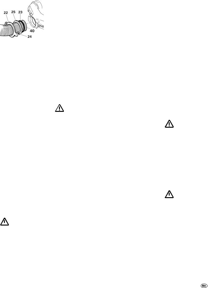
Dichtplatte (22) etwa 3 cm auf das Abgasrohr schieben (Kralle zeigt zum Abgasstutzen der Heizung). Druckring (25) aufschieben. O-Ring (23) durch Ausweiten vorsichtig über die Rohrschnittkante führen und Abgasrohr bis auf Anschlag in den Abgasstutzen stecken.
O-Ring, Druckring und Dichtplatte an den Abgasstutzen heranschieben. Dichtplatte (22) durch Drehen einhängen und mit Schraube (24) fest anziehen.
Nach jeder Demontage muss ein neuer O-Ring
(23) montiert werden.
2.Überrohr (41) auf das Abgasrohr schieben (muss vom Kamin bis zur Rückwand des Einbaukastens reichen, siehe Bild E + D).
3.Bild D + E: Rohre an der Wand mit wenig Krümmungen hochführen. Abgasrohr (40) bis Anschlag in den Kamin einschieben und mit Blechschraube (28) sichern.
Abgasrohr (40) mit Überrohr (41) muss auf
ganzer Länge steigend und mit mehreren Schellen (42) fest und dauerhaft montiert sein, da sich sonst ein Wassersack bilden kann, welcher den freien Abzug der Abgase verhindert.

Gasanschluss
Der Betriebsdruck der Gasversorgung, 30 mbar (bzw. 28 mbar Butan/37 mbar Propan) oder 50 mbar, muss mit dem Betriebsdruck des Gerätes (siehe Fabrikschild,
Bild A: e) übereinstimmen.
Bild G: Die Gaszuleitung (32) muss mit Schneidringverschraubung am Stutzen (33), 8 mm Außendurchmesser, angeschlossen werden.
Der Gasanschlussstutzen an der Heizung
darf nicht verbogen werden! Beim Festziehen des Anschlussnippels diesen sorgfältig mit einem Schlüssel gegenhalten!
Die Rohrverlegung ist so zu wählen, dass für Service-Ar- beiten die Heizung wieder ausgebaut werden kann.
Vor dem Anschluss an die Heizung sicherstellen, dass die Gasleitungen frei von Schmutz, Spänen u.Ä. sind!
Auf Wunsch steht ein Spezialrohr für Innen-Gasanschluss zur Verfügung, das mittels Winkelverschraubung am Gasanschlussstutzen (33) verschraubt wird.
Die Gasanlage muss den technischen und administrativen Bestimmungen des jeweiligen Verwendungslandes entsprechen (in Europa z.B. EN 1949 für Fahrzeuge).
Nationale Vorschriften und Regelungen (in Deutschland z.B. das DVGW-Arbeitsblatt G 607 für Fahrzeuge) müssen beachtet werden.
Heizungsverkleidung
1. Bild G: Griffbuchse (26), falls vorhanden Piezo-Druck- zünder (27) und das integrierte Bedienteil (51) für das Trumavent-Gebläse TEB in die Aussparungen eindrücken (Rechtsoder Linkseinbau beachten!). Freie Aussparungen mit Verschlussdeckel (50) verschließen.
Nur Trumatic S 3002 P:
Massekabel (34) am Druckzünder (27) und am Massekontakt (37) der Verkleidung anstecken.
2.Typenschild (52) in die Sichtfenster-Aussparung eindrücken (Rechtsoder Linkseinbau beachten!).
3.Bei integriertem Bedienteil (51) das Verbindungskabel (53) des Trumavent-Gebläses
TEB am Bedienteil anstecken. Lasche (54) am Einbaukasten nach hinten umbiegen und Verbindungskabel (53) durchführen.
Nur Trumatic S 3002 P:
Flachstecker des Zündkabels (38) auf den Anschluss (36) am Druckzünder (27) schieben und Isolierung (43) aufschieben (siehe Bild A).
Trumatic S 3002 (P)
4. Verkleidung auf die unteren Haltelaschen stellen. Druckstange (11) von unten in die Griffbuchse (26) einführen und Verkleidung oben einrasten lassen. Bedienungsgriff (55) von oben so auf die Druckstange (11) aufstecken, dass der Pfeil zur „0“-Stellung zeigt.
Trumatic S 5002
4. Verkleidung auf die unteren Haltelaschen stellen. Druckstange (11) mit Bedienungsgriff (55) von unten in die Griffbuchse (26) einführen und Verkleidung oben einrasten lassen.
Funktionsprüfung
Nach dem Einbau muss die Dichtheit der Gaszuleitung nach der Druckabfallmethode geprüft werden. Eine Prüfbescheinigung (in Deutschland z.B. gemäß DVGW-Arbeits- blatt G 607) ist auszustellen.
Anschließend gemäß der Gebrauchsanweisung sämtliche Funktionen des Gerätes prüfen.
Die Gebrauchsanweisung mit ausgefüllter Garantiekarte ist dem Fahrzeughalter auszuhändigen.
Warnhinweise
Der dem Gerät beigegebene gelbe Aufkleber mit den Warnhinweisen ist durch den Einbauer bzw. Fahrzeughalter an einer für jeden Benutzer gut sichtbaren Stelle im Fahrzeug (z.B. an der Kleiderschranktür) anzubringen! Aufkleber ggf. bei Truma anfordern.
Besondere
Einbauhinweise
Diese Heizung darf nicht in Reisemobile
eingebaut werden, die für die Zulassung in Deutschland bestimmt sind!
1. Bei Betrieb der Heizung
– insbesondere während der Fahrt – ist unbedingt der Kaminaufsatz T3 (Art.-Nr. 30700-03) erforderlich, der frei im Luftstrom liegen muss. Gegebenenfalls ist zusätzlich eine Kaminverlängerung AKV (Art.-Nr. 3001020800) einzubauen.
Der Reisemobilhersteller bzw. Heizungseinbauer muss die Kombination von Kaminaufsatz und ggf. Verlängerungen bei den einzelnen Auslieferungszuständen der Fahrzeuge durch Versuchsfahrten ermitteln und ggf. mit Truma abstimmen. Abhängig vom Fahrzeugtyp und von den Dachaufbauten kann der Kaminaufsatz
T1 (Art.-Nr. 30700-01) oder
T2 (Art.-Nr. 30700-02) erforderlich sein.
Dachaufbauten sowie verstautes Gepäck im Umkreis des Abgaskamins stören die Funktion der Heizung, insbesondere während der Fahrt. Die Flamme kann dadurch zurückbrennen und Schäden an der Heizung und am Fahrzeug verursachen. In diesen Fällen müssen weitere Kaminverlängerungen verwendet werden, so dass der Kaminaufsatz mindestens
10 cm über die Gegenstände hinausragt. Bei Nichtbeachtung dieser Hinweise besteht kein Garantieanspruch für entstandene Schäden an der Heizung und am Fahrzeug.
2. Wird der Fahrzeugboden mit Unterbodenschutz versehen, müssen alle unter dem Wagen befindlichen Heizungsteile abgedeckt werden, damit der entstehende Spritznebel nicht zu Funktionsstörungen der Heizungsanlage führt. Nach Abschluss der Arbeiten Abdeckungen wieder entfernen.
3.Falls beim Einbau Frisch- luft-Ansaugöffnungen angebracht werden, müssen diese so angeordnet sein, dass keine verunreinigte Luft (Abgase, Benzinoder Öldämpfe) ins Fahrzeuginnere gelangen kann.
4.In Sonderfällen kann es zum Eindringen von Staub usw. kommen. Für diese Fälle empfehlen wir den Einbau eines Dichtungssatzes:
S 3002 (P)
(Art.-Nr. 30030-89800), S 5002
(Art.-Nr. 30050-32700).
5
Trumatic S 3002 P
Trumatic S 3002
Trumatic S 5002
Liquid gas heater
Installation of the heater inside buses or in vehicles for the transportation of hazardous goods is not permissible.
For installation in special-pur- pose vehicles, the regulations applicable in each case must be observed.
Installation
instructions
Installation and repair jobs on the heater are only to be carried out by an expert. Read and follow the installation instructions carefully prior to starting any work!
Intended use
This heater is designed for installation in caravans, mobile homes and other trailer vehicles. It is not approved for installation in boats. Other forms of use are also possible after consultation with Truma.
Approval
Declaration of conformity:
The Trumatic S has been approved by the DVGW and complies with the EC guidelines (90/396/EWG) for gas appliances as well as with the associated EC guidelines. The product ID No. for EU countries is:
S 3002 (P): CE-0085AP0325 S 5002: CE-0085AP0326
The heater is approved for installation in areas frequented by people (in motor vehicles) and, provided the rules and regulations of the respective country are observed, it can also be used while the vehicle is moving.
Information regarding installation in Germany: This heater is not to be installed in motor vehicles (e.g. mobile homes) which are to be registered in Germany.
Truma heaters Trumatic S 3002 K, Trumatic C or
Trumatic E are intended for motor vehicles. These have been approved by the German Federal Office for Motor Vehicles.
For other countries the special instructions must be observed when installing the heater in mobile homes (refer to „Special installation instruction“).
6
Regulations
Any alteration to the appliance (including exhaust duct and cowl) or the use of spare parts and accessories which are essential for the operation of the heater and are not original Truma parts, or the non-observance of the installation and operating instructions, will lead to the cancelling of the guarantee and exclusion of liability claims. It also becomes illegal to use the appliance, and in some countries this even makes it illegal to use the vehicle.
The first year of operation must be marked on the name plate.
Installation in vehicles must accord with the technical and administrative provisions of the individual country of use (e.g. EN 1949). National specifications and regulations (in Germany, for example, DVGW Worksheet G 607) must be respected.
In other countries always observe the respectively valid regulations.
Further details of regulations in various countries of destination can be obtained from our foreign representatives (see Operating Instructions).
The combustion air must not be taken from the vehicle interior. The combustion air must always be obtained from the outside.
Choice of location
1.Always install the appliance and its exhaust gas duct in such a way that it is easily accessible for service work at all times and can be removed and installed easily.
2.As a rule, the heater should be installed inside the wardrobe in the vehicle.
Installation cut-out:
S 3002 (P): 480 x 480 mm S 5002: 510 mm wide, 522 mm high.
For satisfactory operation of the heater it is important that the heater base and bottom
edge of the installation box are assembled on one level so that the control knob is flush with the casing.
3. Using the installation template, check whether the floor cut-out section
(S 3002 (P) 205 x 100 mm, S 5002: 235 x 230 mm) for the combustion air intake is to be on the right or on the left, under the appliance (fig. A shows right-handed installation, fig. G left-hand- ed installation). The combustion air intake is not to be located in the spray area of the wheels (if necessary fit a spray guard).
There should be no heat-sensitive materi-
als under the appliance (cut away carpeting). In the case of PVC flooring, the heating of the heater base may cause some discoloration.
Fig. B: If the heater is installed on a plinth or the like, the intake extension (art. no. 30030-04800, length 50 cm) must be used. The intake extension must be freely suspended in the air flow approximately 5 to 10 cm below the lowest point of the vehicle (shorten if necessary). Two intake extensions are required for the Trumatic S 5002.
The plinth must be sealed from the vehicle interior and must not be made from a combustible material or has to be lined on the inside with sheet metal because of the risk of blow-back under unfavourable wind conditions. To prevent non-burned gas from building up the plinth must have a vent at least 2 cm2 in size at its lowest point, or must be open at the bottom.
4. Exhaust ducts and cowls must be installed in such a way that exhaust gas cannot find its way into the vehicle.
To ensure even and rapid warm air distributi-
on as well as lower surface temperatures on the heating unit, we recommend installing a Trumavent warm-air system.
If desired, the Trumatic S 5002 heating system is also available with a special
installation box for two Trumavent fans.
Preparatory work and installation boxes
1.Secure the template for the floor opening in the cutout section by means of thumb tacks, the arrow must point exactly to the front edge of the opening
(R = right-hand installation, L = left-hand installation).
2.Cut the floor opening using a saw and pre-drill 5 holes for the fixing screws. The exact dimensions must be observed!
3.Fig. A: Insert half-frames
(5) in the floor opening and press them outwards and screw tight (pretension as needed by bending the sides upward so that the frame fits firmly).
4.Fig. D: Break out the prestamped apertures for the waste gas pipe on the outer part of the installation box (R = right-hand installation, L = left-hand installation). If
the installation depth is small, the waste gas pipe can also be conducted through the side with the S 5002 heating system (R1 or L1).
When installing the special pipe for internal gas connection (refer to „Gas Connection”), break out both apertures.
If a Trumavent fan and/or Truma-Ultraheat
electrical supplementary heating are being fitted, remove the pre-stamped cover
(T) or (U) respectively, and fit the units to the installation box in accordance with the installation instructions provided in each case.
5. Fig. C: Separate the outer part (1) and inner part (2) of the installation box, and secure them with 5 sheet metal screws (19).
For the S 5002 heating system, the screws
19a must be used for righthand installation and the screws 19b for left-hand installation.
Firmly screw in the 3 screws (35), even if you are not installing a Trumavent fan.
6. Place the pre-assembled installation box in the opening and screw at an angle to the outside using 6 bolts (6) respectively.
Installation of the heater
Trumatic S 3002 P
1. Fig. A: Place the heater unit in the floor opening. Plug the thermostat probe with the screening plate (7) in the slot (8) and slide it under the attachment piece (9) until you hear it engage (fig. A shows right-hand installation, fig. G shows left-hand installation).
The thermostat probe (7) must always be at
the front of the heater (facing the room). Thermostat probe
(7) and the capillary tube (10) must never touch the heat exchanger or the heater casing!
2.Fig. C: Slide heater to the rear spacer brackets (18) in the installation box.
3.Fig. A: Fasten heater with 5 screws (3) to the pre-drilled points in the corners and at the front in the center. If necessary, reinforce the floor structure with battens.
4.Fig. A: Press ground spring (30) out of the transportation safety device so that it rests against the installation box (otherwise the ignition will not work).
5.Fig. A: Insert push rod with eye spring (11) into the ignition safety valve (12).
Fasten ignition cable (38) on the side of the push rod in the 3 retaining straps (39) of the installation box.
Trumatic S 3002
1. Fig. A: Place the heater unit in the floor opening. Plug the thermostat probe with the screening plate (7) in the slot (8) and slide it under the attachment piece (9) until you hear it engage (fig. A shows right-handed installation,
fig. G shows left-hand installation).
The thermostat probe  (7) and automatic ignitor (15) must always be at the front of the heater (facing the room). The thermostat probe
(7) and the capillary tube (10) must never touch the heat exchanger or the heater casing!
2. Fig C: Slide heater to the rear spacer brackets (18) in the installation box.
3.Fig A: Remove automatic ignitor (15) from its mount. Fasten heater with 5 screws
(3) to the pre-drilled points in the corners and at the front in the center. If necessary, reinforce the floor structure with battens.
4.Check the automatic ignition device (15) to ensure that the plug-in connections
(13 + 14) are mounted properly. Then push the automatic ignition device (15) into the link plates (16) as far as the stop (fig. A shows right-hand installation, fig. G shows lefthand installation).
5.Fig. A: Insert push rod with eye spring (11) into the ignition safety valve (12).
Trumatic S 5002
1. Fig. A: Place the heater unit in the floor opening. Insert the thermostat probe (7) with screening plate into strap (8) and fasten it with self-tapping screw (9). (fig. A shows right-hand installation, fig. G shows left-hand installation).
Thermostat probe (7) and automatic ignitor
(15) must always be at the front of the heater (facing the room). Thermostat probe (7) and capillary tube (10) must never be allowed to touch the heat exchanger or heater casing!
2.Fig A: Remove automatic ignitor (15) from its holder. Fasten the heater by means of the 5 screws (3) (holes are pre-punched in the corners and front centre). If necessary, reinforce the floor structure with battens.
3.Check the automatic ignition device (15) to ensure that the plug-in connections
(13 + 14) are mounted properly. Then push the automatic ignition device (15) into the link plates (16) as far as the stop (fig. A shows right-hand installation, fig. G shows lefthand installation).
4.Fig. A: Insert push rod with eye spring (11) into ignition safety valve (12). Insert control knob (55) onto push rod (11) so that the arrow points to „0” (heater middle position).
Exhaust gas cowl
The heater is only approved when used with a roof cowl. This must be installed vertically or with no more than a 15 degree slope!
Fig. F: Position the roof cowl so that the duct (minimum length 1.5 m, maximum length 3 m) can be routed direct from the heater unit, sloping upward all the way to the cowl. A 1.5 metre long duct must reach a height of at least 1 metre. The remainder of the duct to the roof cowl must be installed more or less vertically.
Trumatic S 3002 (P)
Fig. E: Cut out an opening with a Ø of 60 mm at a centre distance of at least 55 mm from the side walls.
Trumatic S 5002
1. Fig. E: Cut out an opening with a Ø of 70 mm at a centre distance of at least 60 mm from the side walls.
2 Fig. E: In the case of a double-skin roof, line the cavity with wood or slide in a rolled circular sheet metal strip (20) of about 220 mm in length and 1 mm in thickness, to stiffen the roof so that when the screws are tightened it does not warp and stays weatherproof.
3. Fig. E: Push the cowl through the roof from above and fasten it on the inside with screw ring (21). Next, secure the screw ring (21) with a screw (44).
Use the enclosed rubber sealing ring without further sealing materials.
Exhaust duct
For the Trumatic S, only the Truma stainless-steel waste gas pipe AE 3 or AE 5 with the Truma pipe sheath UR or UR 5 (APP) may be used, since the devices have only been tested and approved in conjunction with these pipes.
Length of exhaust duct: min. 1.5 m, max. 3 m!
Fitting and bending the stainless steel duct and stretching open the O-ring are made considerably easier by using „Biege-Boy“ (Art. no. 3003033000).
1. Connecting the exhaust duct to the heater:
Slide sealing plate (22) about 3 cm onto the exhaust duct (with the claw pointing towards the heater exhaust outlet). Slide on pressure ring (25). Stretch open O-Ring (23) and carefully pass it over the cut edge of the duct. Then plug the exhaust duct into the exhaust outlet as far as the stop.
Slide the O-ring, pressure ring and sealing plate to the exhaust outlet. Twist on sealing plate (22) and fasten it securely by tightening screw (24).
A new O-ring (23) must be fitted each time the
exhaust duct is dismantled.
2.Slide insulating duct (41) onto the exhaust duct (it must reach from the cowl to the rear wall of the installation box, refer to fig. E + D).
3.Fig. D + E: Take the ducting up the wall with as few bends as possible. Slide exhaust gas duct (40) into the cowl as far as the stop and secure with self-tapping screw (28).
Exhaust gas duct (40)  with its insulating duct (41) must be sloping upward over its whole length and fitted securely and permanently
with several clamps (42), otherwise a water trap may form, obstructing the free passage of the exhaust gases.
Gas connection
The operating pressure of the gas supply, 30 mbar (28 mbar butane/37 mbar propane) or 50 mbar must correspond to the operating pressure of the appliance (refer to name plate, fig. A e).
7
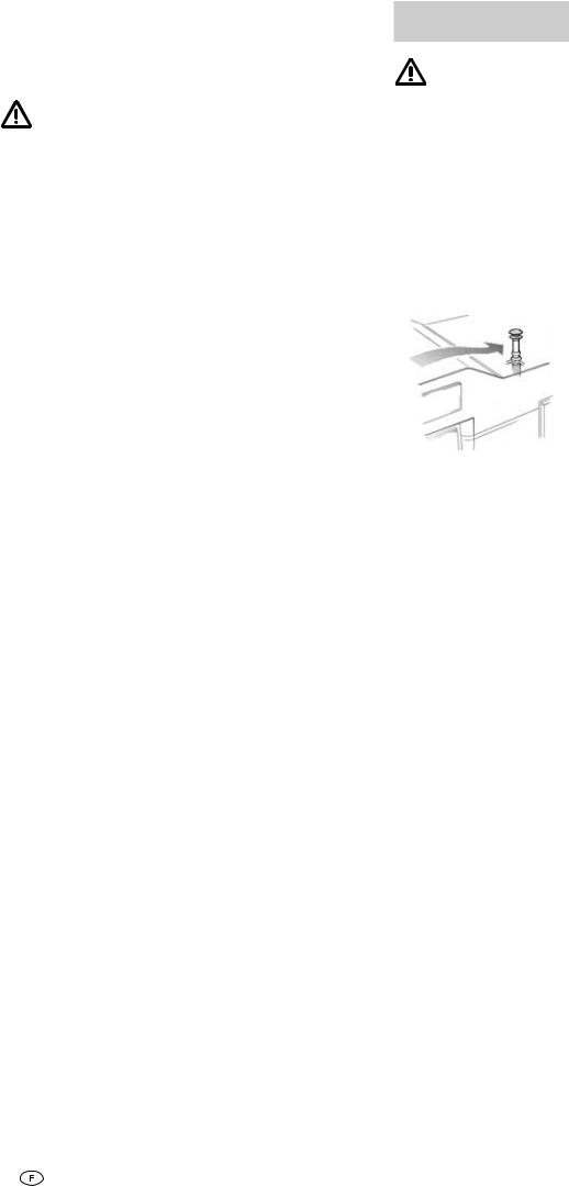
Fig. G: The gas supply pipe (32) must be connected using a cutting ring screw fitting with an outer diameter of 8 mm at the connecting piece (33).
The gas connection fitting on the heating ap-
pliance must not be bent! When tightening the connection nipple, hold it carefully in place with a second wrench!
Route the ducting in such a way that the heater can be removed for servicing work.
Make sure the gas lines are free of dirt, chips and such prior to connecting!
A special duct for internal gas connection is available on request. It is screwed onto gas connection fitting (33) with an elbow.
The gas system must accord with the technical and administrative provisions of the individual country of use (in Europe, for example, EN 1949 for motor vehicles).
National regulations and rulings (in Germany, for example, the DVGW worksheet G 607 for motor vehicles) must be respected.
Heater casing
1. Fig. G: Push the handle connector (26), the piezo pressure igniter (27) if applicable, and the integrated operating element (51) for the Trumavent TEB fan into the cut-outs (take care to respect right-hand or left-hand installation). Close off any unoccupied cut-outs with the closure cover (50).
For Trumatic S 3002 P only:
Plug the earthing cable (34) to the pressure igniter (27) and the earth contact (37) on the casing.
2.Press type plate (52) into the observation window opening (note right-handed or left-handed installation!).
3.With integrated control panel (51) plug connecting cable (53) of the Trumavent fan TEB into the control panel. Bend back strap (54) on the installation box and insert connecting cable (53).
For Trumatic S 3002 P only:
Slide flat connector of ignition cable (38) on the connection (36) on the piezo ignitor (27) and slide on insulation (43 – refer to fig. A).
8
Trumatic S 3002 (P)
4. Place the casing onto the lower retaining shackles. Guide the pressure rod (11) from below into the handle connector (26) and engage the casing at the top. Push the operating handle (55) from above onto the pressure bar (11) in such a way that the arrow points to the „0“ position.
Trumatic S 5002
4. Place the casing onto the lower retaining shackles. Guide the pressure rod (11) with operating handle (55) from below into the handle connector (26) and engage the case at the top.
Function check
After installation, the sealing tightness of the gas feed line must be tested in accordance with the pressure drop method. A test certificate (in Germany, for example, in accordance with the DVGW operational data sheet G 607) is to be issued.
Following this inspection, test all functions of the appliance as specified in the operating instructions.
The operating instructions and completed guarantee card are to be given to the owner of the vehicle.
Warning information
The installer or vehicle owner must display the yellow sticker with the warning information, enclosed with the appliance, in the vehicle so it is clearly visible to all users (e.g. on the wardrobe door)! Ask Truma to send you a sticker if necessary.
Special installation
instructions
This heater is not to be installed in mobile
homes intended for registration in Germany!
1. Cowl top T3 (art. no.
30700-03) must always be installed when the heater is operating – particularly when the vehicle is moving. It must be positioned in the unobstructed slipstream. If necessary, install a cowl extension AKV (art. no. 3001020800).
The camper manufacturer or heater installer must perform test drives to determine the combination of flue top and extensions (if required) for the individual as-delivered vehicle configurations and consult Truma if necessary. Depending on the vehicle model and the equipment installed on the roof, flue top
T1 (art. no. 30700-01) or
T2 (art. no. 30700-02) may be required.
Roof extensions and luggage stowed in the vicinity of the exhaust cowl impede the operation of the heater, especially when the vehicle is moving. The flame may flash back, causing damage to the heater and vehicle. In this case, additional cowl extensions must be used so that the top of the cowl projects at least 10 cm above any objects. Failure to observe this will result in the refusal of any guarantee claim for resulting damage to the heater and vehicle.
2. If the vehicle floor is given a body underseal, all parts of the heater located under the vehicle must be covered up so that the underseal spray does not impede the operation of the heater system. The covers must be removed again when the work is finished.
3.If fresh air intake vents are installed they must be positioned so that air which has been polluted (such as by exhaust gases, petrol fumes or oil vapour) cannot find its way into the vehicle.
4.In exceptional cases dust penetration etc. may occur. For these cases we recommend installing a sealing kit: S 3002 (P)
(art. no. 30030-89800), S 5002
(art. no. 30050-32700).
 Loading...