TRSYS P6SMBJ10, P6SMBJ100CA, P6SMBJ10C, P6SMBJ110C, P6SMBJ110 Datasheet
...
P6SMBJ SERIES
SURFACE MOUNT TRANSIENT VOLTAGE SUPPRESSOR
VOLTAGE - 5.0 TO 170 Volts |
Peak Power Pulse - 600Watt |
FEATURES |
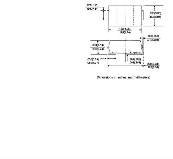
SMB/DO-214AA |
•For surface mounted applications in order to optimize board space
•Low profile package
•Built-in strain relief
•Glass passivated junction
•Low inductance
•Excellent clamping capability
•Repetition Rate(duty cycle):0.01%
•Fast response time: typically less than
1.0 ps from 0 volts to BV for unidirectional types
•Typical ID less than 1 A above 10V
•High temperature soldering :
260 /10 seconds at terminals
• Plastic package has Underwriters Laboratory Flammability Classification 94V-O
MECHANICAL DATA
Case: JEDEC DO-214AA molded plastic over passivated junction
Terminals: Solder plated, solderable per
MIL-STD-750, Method 2026
Polarity: Color band denotes positive end(cathode) except Bidirectional
Standard packaging:12 mm tape per(EIA 481)
Weight: 0.003 ounce, 0.093 gram
MAXIMUM RATINGS AND ELECTRICAL CHARACTERISTICS
Ratings at 25 ambient temperature unless otherwise specified.
|
SYMBOL |
VALUE |
UNITS |
Peak Pulse Power Dissipation on 10/1000 s waveform |
PPPM |
Minimum 600 |
Watts |
(Note 1,2,Fig 1) |
|
|
|
Peak Pulse Current on 10/1000 s waveform |
IPPM |
See Table 1 |
Amps |
(Note 1,Fig 3) |
|
|
|
Peak forward Surge Current 8.3ms single half sine-wave |
IFSM |
100.0 |
Amps |
superimposed on rated load(JEDEC Method) (Note 2,3) |
|
|
|
Operating Junction and Storage Temperature Range |
TJ,TSTG |
-55 to +150 |
|
NOTES:
1.Non-repetitive current pulse, per Fig. 3 and derated above TA=25 per Fig. 2.

2.Mounted on 5.0mm2 (.013mm thick) land areas.
3.Measured on 8 .3ms, single half sine-wave or equivalent square wave, duty cycle= 4 pulses per minutes maximum.
MAXIMUM RATINGS AND CHARACTERISTIC CURVES P6SMBJ SERIES
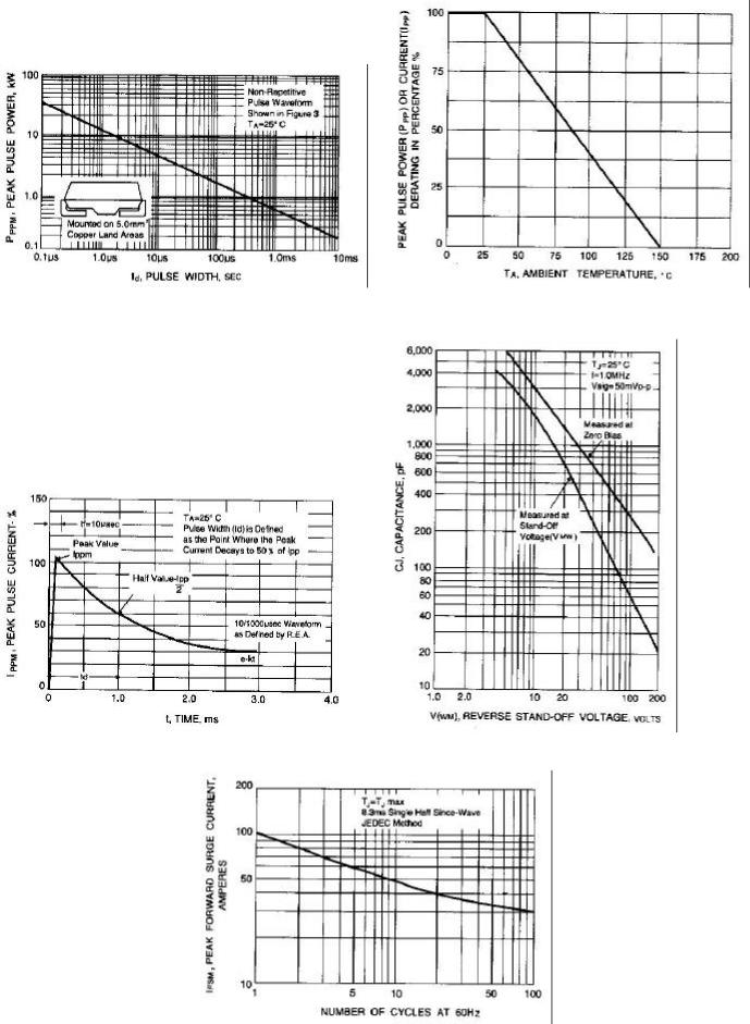
Fig. 1-PEAK PULSE POWER RATING VERSUS |
Fig. 2-PULSE RATING CURVE |
Fig. 3-PULSE WAVEFORM |
Fig. 4-TYPICAL JUNCTION |
CAPACITANCE |
|
Fig. 5- MAXIMUM NON-REPETITIVE PEAK
FORWARD SURGE CURRENT
 Loading...