

Page 1

m _ _ _iiN w v
Operator's Manual
4-Cycle Gasoline Trimmer
TB575SS &
TB525CS
SAVE THESE INSTRUCTIONS
For service call 1-800-520-5520 to obtain a list of authorized
service dealers near you. For more details about your unit, visit
our website at www.troybilt.com.
DO NOT RETURN THE UNIT TO THE RETAILER. PROOF OF
PURCHASE WILL BE REQUIRED FOR WARRANTY
SERVICE.
THIS PRODUCT IS COVERED BY ONE OR MORE U.S.
PATENTS. OTHER PATENTS PENDING.
Service on this unit both within and after the warranty period
should be performed only by an authorized and approved
service dealer.
®
SPARK ARRESTOR NOTE
NOTE: For users on U.S. Forest Land and in the states of
California, Maine, Oregon and Washington. All U.S. Forest
Land and the state of California (Public Resources Codes 4442
and 4443), Oregon and Washington require, by law that certain
internal combustion engines operated on forest brush and/or
grass-covered areas be equipped with a spark arrestor,
maintained in effective working order, or the engine be
constructed, equipped and maintained for the prevention of
fire. Check with your state or local authorities for regulations
TABLE OF CONTENTS
Service Information .............................. 1
Rules for Safe Operation .......................... 2
Know Your Unit ................................. 3
Assembly Instructions ............................ 3
Oil and Fuel Information ........................... 4
Starting/Stopping Instructions ...................... 5
Operating Instructions ............................ 6
Maintenance and Repair Instructions ................ 8
Cleaning and Storage ........................... 13
Troubleshooting Chart ........................... 14
Specifications ................................. 15
Warranty Information ............................ 17
Parts List .................................... E18
WARNING: When using the unit, you must follow
the safety rules. Please read these instructions
before operating the unit in order to ensure the
safety of the operator and any bystanders. Please
keep these instructions for later use.
P/N 769-01920 (11/05)
pertaining to these requirements. Failure to follow these
requirements could subject you to liability or a fine. This unit is
factory equipped with a spark arrestor. If it requires
replacement, ask your LOCAL SERVICE DEALER to install the
Accessory Part #753-05297 Spark Arrestor Kit.
CALIFORNIA PROPOSITION 65 WARNING
THE ENGINE EXHAUST FROM THIS PRODUCT CONTAINS
CHEMICALS KNOWN TO THE STATE OF CALIFORNIA TO
CAUSE CANCER, BIRTH DEFECTS OR OTHER
REPRODUCTIVEHARM.
All information, illustrations, and specifications in this manual
are based on the latest product information available at the
time of printing. We reserve the right to make changes at any
time without notice.
Copyright@ 2005 MTD SOUTHWEST INC, All Rights Reserved.
Page 2
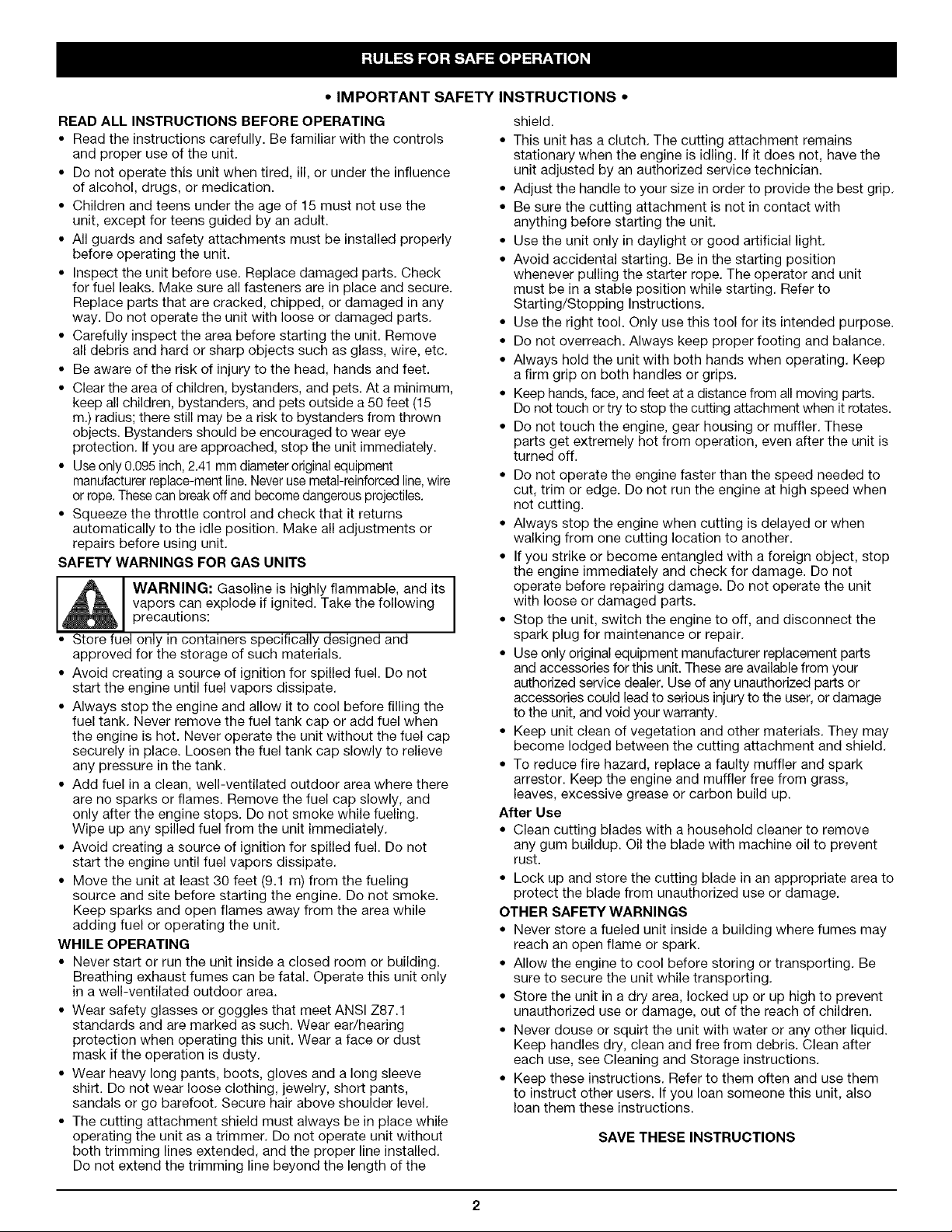
• IMPORTANT SAFETY INSTRUCTIONS °
READ ALL INSTRUCTIONS BEFORE OPERATING
• Read the instructions carefully. Be familiar with the controls
and proper use of the unit.
• Do not operate this unit when tired, ill, or under the influence
of alcohol, drugs, or medication.
• Children and teens under the age of 15 must not use the
unit, except for teens guided by an adult.
• All guards and safety attachments must be installed properly
before operating the unit.
• Inspect the unit before use. Replace damaged parts. Check
for fuel leaks. Make sure all fasteners are in place and secure.
Replace parts that are cracked, chipped, or damaged in any
way. Do not operate the unit with loose or damaged parts.
• Carefully inspect the area before starting the unit. Remove
all debris and hard or sharp objects such as glass, wire, etc.
• Be aware of the risk of injury to the head, hands and feet.
• Clear the area of children, bystanders, and pets. At a minimum,
keep all children, bystanders, and pets outside a 50 feet (15
m.) radius; there still may be a risk to bystanders from thrown
objects. Bystanders should be encouraged to wear eye
protection. If you are approached, stop the unit immediately.
• Useonly 0.095 inch,2.41 mm diameteroriginalequipment
manufacturer replace-ment line. Never use metal-reinforced line,wire
or rope. Thesecan breakoff and become dangerous projectiles.
• Squeeze the throttle control and check that it returns
automatically to the idle position. Make all adjustments or
repairs before using unit.
SAFETY WARNINGS FOR GAS UNITS
vapors can explode if ignited. Take the following
WARNING: Gasoline is highly flammable, and its
precautions:
• Store fuel only in containers specifically designed and
approved for the storage of such materials.
• Avoid creating a source of ignition for spilled fuel. Do not
start the engine until fuel vapors dissipate.
• Always stop the engine and allow it to cool before filling the
fuel tank. Never remove the fuel tank cap or add fuel when
the engine is hot. Never operate the unit without the fuel cap
securely in place. Loosen the fuel tank cap slowly to relieve
any pressure in the tank.
• Add fuel in a clean, well-ventilated outdoor area where there
are no sparks or flames. Remove the fuel cap slowly, and
only after the engine stops. Do not smoke while fueling.
Wipe up any spilled fuel from the unit immediately.
• Avoid creating a source of ignition for spilled fuel. Do not
start the engine until fuel vapors dissipate.
• Move the unit at least 30 feet (9.1 m) from the fueling
source and site before starting the engine. Do not smoke.
Keep sparks and open flames away from the area while
adding fuel or operating the unit.
WHILE OPERATING
• Never start or run the unit inside a closed room or building.
Breathing exhaust fumes can be fatal. Operate this unit only
in a well-ventilated outdoor area.
• Wear safety glasses or goggles that meet ANSI Z87.1
standards and are marked as such. Wear ear/hearing
protection when operating this unit. Wear a face or dust
mask if the operation is dusty.
• Wear heavy long pants, boots, gloves and a long sleeve
shirt. Do not wear loose clothing, jewelry, short pants,
sandals or go barefoot. Secure hair above shoulder level.
• The cutting attachment shield must always be in place while
operating the unit as a trimmer. Do not operate unit without
both trimming lines extended, and the proper line installed.
Do not extend the trimming line beyond the length of the
shield.
• This unit has a clutch. The cutting attachment remains
stationary when the engine is idling. If it does not, have the
unit adjusted by an authorized service technician.
• Adjust the handle to your size in order to provide the best grip.
• Be sure the cutting attachment is not in contact with
anything before starting the unit.
• Use the unit only in daylight or good artificial light.
• Avoid accidental starting. Be in the starting position
whenever pulling the starter rope. The operator and unit
must be in a stable position while starting. Refer to
Starting/Stopping Instructions.
• Use the right tool. Only use this tool for its intended purpose.
• Do not overreach. Always keep proper footing and balance.
• Always hold the unit with both hands when operating. Keep
a firm grip on both handles or grips.
• Keep hands, face, and feet at a distance from all moving parts.
Do not touch or try to stop the cutting attachment when it rotates.
• Do not touch the engine, gear housing or muffler. These
parts get extremely hot from operation, even after the unit is
turned off.
• Do not operate the engine faster than the speed needed to
cut, trim or edge. Do not run the engine at high speed when
not cutting.
• Always stop the engine when cutting is delayed or when
walking from one cutting location to another.
• If you strike or become entangled with a foreign object, stop
the engine immediately and check for damage. Do not
operate before repairing damage. Do not operate the unit
with loose or damaged parts.
• Stop the unit, switch the engine to off, and disconnect the
spark plug for maintenance or repair.
• Use only original equipment manufacturer replacement parts
and accessories for this unit. These are available from your
authorized service dealer. Use of any unauthorized parts or
accessories could lead to serious injury to the user, or damage
to the unit, and void your warranty.
• Keep unit clean of vegetation and other materials. They may
become lodged between the cutting attachment and shield.
• To reduce fire hazard, replace a faulty muffler and spark
arrestor. Keep the engine and muffler free from grass,
leaves, excessive grease or carbon build up.
After Use
• Clean cutting blades with a household cleaner to remove
any gum buildup. Oil the blade with machine oil to prevent
rust.
• Lock up and store the cutting blade in an appropriate area to
protect the blade from unauthorized use or damage.
OTHER SAFETY WARNINGS
• Never store a fueled unit inside a building where fumes may
reach an open flame or spark.
• Allow the engine to cool before storing or transporting. Be
sure to secure the unit while transporting.
• Store the unit in a dw area, locked up or up high to prevent
unauthorized use or damage, out of the reach of children.
• Never douse or squirt the unit with water or any other liquid.
Keep handles dry, clean and free from debris. Clean after
each use, see Cleaning and Storage instructions.
• Keep these instructions. Refer to them often and use them
to instruct other users. If you loan someone this unit, also
loan them these instructions.
SAVE THESEINSTRUCTIONS
Page 3
SAFETY AND INTERNATIONAL SYMBOLS
This operator's manual describes safety and international symbols and pictographs that may appear on this product. Read the
operator's manual for complete safety, assembly, operating and maintenance and repair information.
SYMBOL MEANING
'SAFETyALERTSyMBOL
Indicates danger, warning or cautio n . MaY be used
n con unct on wth other symb0 s or p ctographs.
• WARNING ,READ OPERATOR'S MANUAL
Read the Operator's manual(s ) and follow all warning s
and safety instructions. Failure to de SOcan result in
serious injury to the operate[ and/or bystanders,
• WEAR EYE AND HEARING PROTECTION
WARNING: Thrown objects and loud noise can
cause severe eye injury and hearing loss. Wear eye
protection meeting ANSI Z87.1 standards and ear
protection when operating th! s unit. Use a fuHface
HOTSU,FAOEWA,N,,G
De not touch a hot muffler, gear housing or cylinder.
_1_1, from operation. They remain hot for a short time after
N%' UNLEADED FUEL
_ Always use clean fresh unleaded fuel
you may get burned. These parts get extremely hot
the unit is turned 0ff.
SYMBOL
A
H lq I 'l
MEANING
• KEEP BYSTANDERS AWAY
WARNING: Keep all bystaneers, espectaHy
childrer and Pets. at least 50 feet (15 m) from the
operating area.
• CHOKE CONTROL
1. • FULL choke oosition
2. • PARTIAL choke position
3. • RUN choke position
• THROWN OBJECTS AND ROTATING CUTTER
CAN CAUSE SEVERE INJURY
WARNING: Do not operate without the cutting
attachment shield n elace. Keep away from me
Lting cutting attachmen]
• SHARP BLADE
cutting attachment
To prevent serious tnjury do not touch the
ne cutnng blade.
• ON/OFF STOP CONTROL
OK START / RUN
_7 _ Refer to Operator s manual for the propel type o!
' O!L ;
oil.
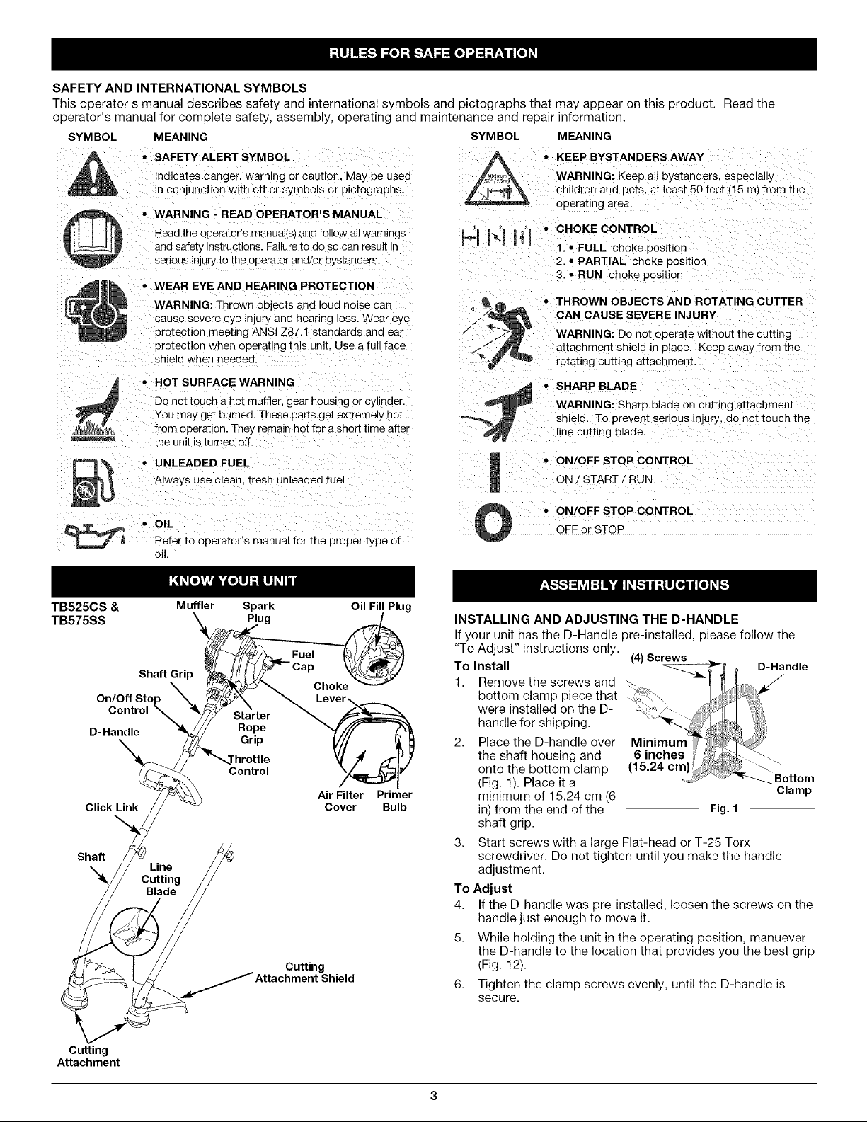
TB525CS & Muffler Spark Oil Fill Plug
TB575SS Plug
Fuel
Shaft Grip
On/Off Stop
Control _ Starter
D-Handle Rope
Click Link
Shaft
•X4 Line
Cutting
Blade
Grip
Control
Choke
Air Filter Primer
Cover Bulb
Cutting
• ON/OFF STOP CONTROL
OFF or STOP
INSTALLING AND ADJUSTING THE D-HANDLE
If your unit has the D-Handle pre-installed, please follow the
"To Adjust" instructions only.
To Install (4)Screws D-Handle
1. Removethe screws and f
bottom clamp piece that
were installed on the D-
handle for shipping.
2. Place the D-handle over Minimum
the shaft housing and 6 inches _ _
onto the bottom clamp (15.24 cm) -_.
(Fig. 1). Place it a Bottom
minimum of 15.24 cm (6 Clamp
in) from the end of the Fig. 1
shaft grip.
3. Start screws with a large Flat-head or T-25 Torx
screwdriver. Do not tighten until you make the handle
adjustment.
To Adjust
4. If the D-handle was pre-installed, loosen the screws on the
handle just enough to move it.
5. While holding the unit in the operating position, manuever
the D-handle to the location that provides you the best grip
(Fig. 12).
6. Tighten the clamp screws evenly, until the D-handle is
secure.
Cutting
Attachment
Page 4
WARNING: To avoid serious personal injury, the
cutting attachment shield MUST be in place at all
times while operating the unit as a trimmer.
WARNING: OVERFILLING OIL CRANKCASE MAY
CAUSE SERIOUS PERSONAL INJURY. Check and
maintain the proper oil level in the crank case; it is
important and cannot be overemphasized. Check
the oil before each use and change it as needed.
See Chanqinq the Oil.
RECOMMENDED OIL TYPE
Using the proper type and weight of oil in the crankcase is
extremely important. Check the oil before each use and change
the oil regularly. Failure to use the correct oil, or using dirty oil,
can cause premature engine wear and failure.
Use a high-quality SAE 30 weight oil of API (American Petroleum
Institute) service class SF, SG, SH.
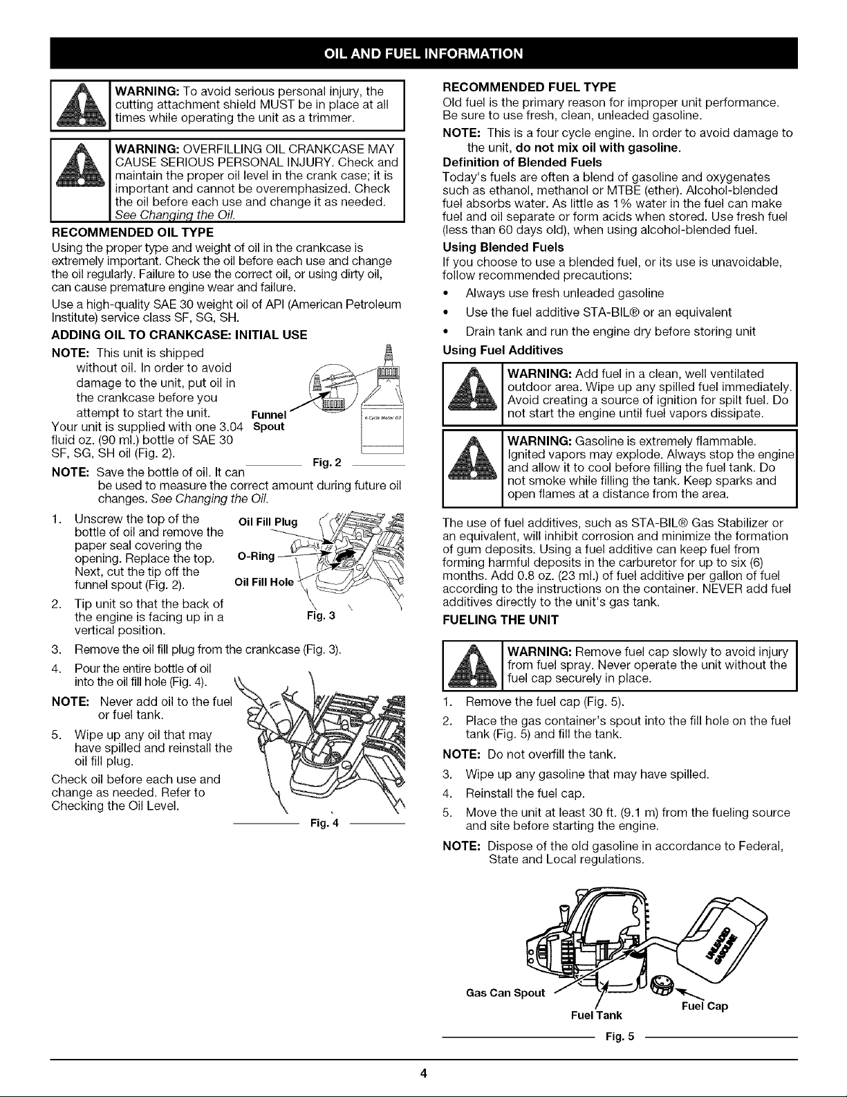
ADDING OIL TO CRANKCASE: INITIAL USE
NOTE: This unit is shipped
without oil. In order to avoid
damage to the unit, put oil in
the crankcase before you
attempt to start the unit. Funnel
Your unit is supplied with one 3.04 Spout
fluid oz. (90 ml.) bottle of SAE 30
SF, SG, SH oil (Fig. 2).
NOTE: Save the bottle of oil. It can
be used to measure the correct amount during future oil
changes. See Changing the Oil.
1. Unscrew the top of the Oil Fill Plug __
bottle of oil and remove the _ _y._\__
paper seal covering the
opening. Replace the top. O-Ring _-_'_t_/_. _
Next, cut the tip off the
funnel spout (Fig. 2). Oil Fill Hole
2. Tip unit so that the back of
the engine is facing up in a Fig.3
vertical position.
3.
Remove the oil fill plug from the crankcase (Fig. 3).
4.
Pour the entire bottle of oil
into the oil fill hole (Fig. 4).
NOTE:
5. Wipe up any oil that may
Check oil before each use and
change as needed. Refer to
Checking the Oil Level.
Never add oil to the fuel
or fuel tank.
have spilled and reinstall the
oil fill plug.
Fig. 2
Fig. 4
RECOMMENDED FUEL TYPE
Old fuel is the primary reason for improper unit performance.
Be sure to use fresh, clean, unleaded gasoline.
NOTE: This is a four cycle engine. In order to avoid damage to
the unit, do not mix oil with gasoline.
Definition of Blended Fuels
Today's fuels are often a blend of gasoline and oxygenates
such as ethanol, methanol or MTBE (ether). Alcohol-blended
fuel absorbs water. As little as 1% water in the fuel can make
fuel and oil separate or form acids when stored. Use fresh fuel
(less than 60 days old), when using alcohol-blended fuel.
Using Blended Fuels
If you choose to use a blended fuel, or its use is unavoidable,
follow recommended precautions:
• Always use fresh unleaded gasoline
• Use the fuel additive STA-BIL® or an equivalent
• Drain tank and run the engine dry before storing unit
Using Fuel Additives
outdoor area. Wipe up any spilled fuel immediately.
l_ WARNING: Add fuel in a clean, well ventilated
M Avoid creating a source of ignition for spilt fuel. Do
not start the engine until fuel vapors dissipate.
,_m _ WARNING: Gasoline is extremely flammable.
The use of fuel additives, such as STA-BIL® Gas Stabilizer or
an equivalent, will inhibit corrosion and minimize the formation
of gum deposits. Using a fuel additive can keep fuel from
forming harmful deposits in the carburetor for up to six (6)
months. Add 0.8 oz. (23 ml.) of fuel additive per gallon of fuel
according to the instructions on the container. NEVER add fuel
additives directly to the unit's gas tank.
FUELING THE UNIT
1. Remove the fuel cap (Fig. 5).
2. Place the gas container's spout into the fill hole on the fuel
tank (Fig. 5) and fill the tank.
NOTE: Do not overfill the tank.
3. Wipe up any gasoline that may have spilled.
4. Reinstall the fuel cap.
5. Move the unit at least 30 ft. (9.1 m) from the fueling source
and site before starting the engine.
NOTE: Dispose of the old gasoline in accordance to Federal,
Ignited vapors may explode. Always stop the engine
and allow it to cool before filling the fuel tank. Do
° not smoke while filling the tank. Keep sparks and
open flames at a distance from the area.
WARNING: Remove fuel cap slowly to avoid injury I
from fuel spray. Never operate the unit without the
fuel cap securely in place.
State and Local regulations.
I
Gas Can Spout
FuelTank
Fuel Cap
Fig. 5
Page 5
ventilated outdoor area. Carbon monoxide exhaust
WARNING: Operate this unit only in a well-
fumes can be lethal in a confined area.
WARNING: Avoid accidental starting. Make sure
you are inthe starting position when pulling the
starter rope (Fig. 8). To avoid serious injuw, the
operator and unit must be in a stable position while
starting.
To avoid serious personal injuw, ensure any Add-
On being used is installed correctly and secure
before starting the unit.
STARTING INSTRUCTIONS
1, Check the oil level in the crankcase. Refer to
Checking the Oil Level.
2, Fill the fuel tank with fresh, clean unleaded gasoline.
Refer to Fueling the Unit,
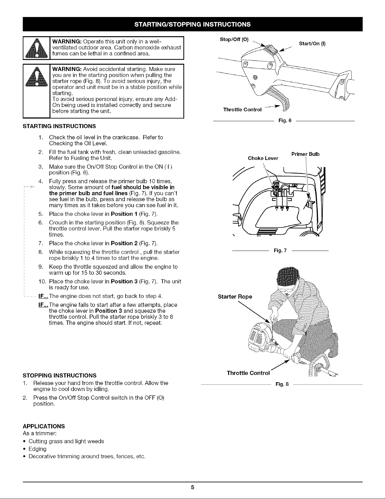
3, Make sure the On/Off Stop Control in the ON ( I )
position (Fig. 6).
4, Fully press and release the primer bulb 10 times,
slowly. Some amount of fuel should be visible in
the primer bulb and fuel lines (Fig. 7). If you can't
see fuel in the bulb, press and release the bulb as
many times as it takes before you can see fuel in it.
5. Place the choke lever in Position 1 (Fig. 7).
6. Crouch in the starting position (Fig. 8). Squeeze the
throttle control lever. Pull the starter rope briskly 5
times.
7. Place the choke lever in Position 2 (Fig. 7).
8. While squeezing the throttle control, pull the starter
rope briskly 1 to 4 times to start the engine.
9. Keep the throttle squeezed and allow the engine to
warm up for 15 to 30 seconds.
10. Place the choke lever in Position 3 (Fig. 7). The unit
is ready for use.
...............IF...The engine does not start, go back to step 4.
IF...The engine fails to start after a few attempts, place
the choke lever in Position 3 and squeeze the
throttle control. Pull the starter rope briskly 3 to 8
times. The engine should start. If not, repeat.
Stop/Off (O)
Throttle Control
Starter Rope
Choke Lever
Start/On (I)
Fig. 6
Primer Bulb
Fig. 7
STOPPING INSTRUCTIONS
1. Release your hand from the throttle control. Allow the
engine to cool down by idling.
2. Press the On/Off Stop Control switch in the OFF (O)
position.
APPLICATIONS
As a trimmer:
• Cutting grass and light weeds
• Edging
• Decorative trimming around trees, fences, etc.
Throttle Control
Fig. 8
Page 6
OPERATING THE EZ-LINK TM SYSTEM
The EZ-Link TM system enables the use of these optional Add-
Ons:
Cultivator ..................................... TBGC
Edger ........................................ TBLE
Hedge Trimmer ................................ TBAH
Straight Shaft Trimmer ........................... TBSS
Turbo Blower .................................. TBTB
Pole Saw ..................................... TBPS
Brushcutter ................................... TBBC*
*Do NOT use this attachment with an electric powered unit.
WARNING: Before you begin using any
attachment, read and understand the manual that
came with the attachment. Follow all safety
information contained within.
Removing the Cutting Attachment or Add-On
1. Turn the knob counterclockwise to loosen (Fig. 9).
2. Press and hold the release button (Fig. 9).
3. While firmly holding the upper shaft housing, pull the
cutting attachment or add-on straight out of the EZ-Link TM
coupler (Fig. 10).
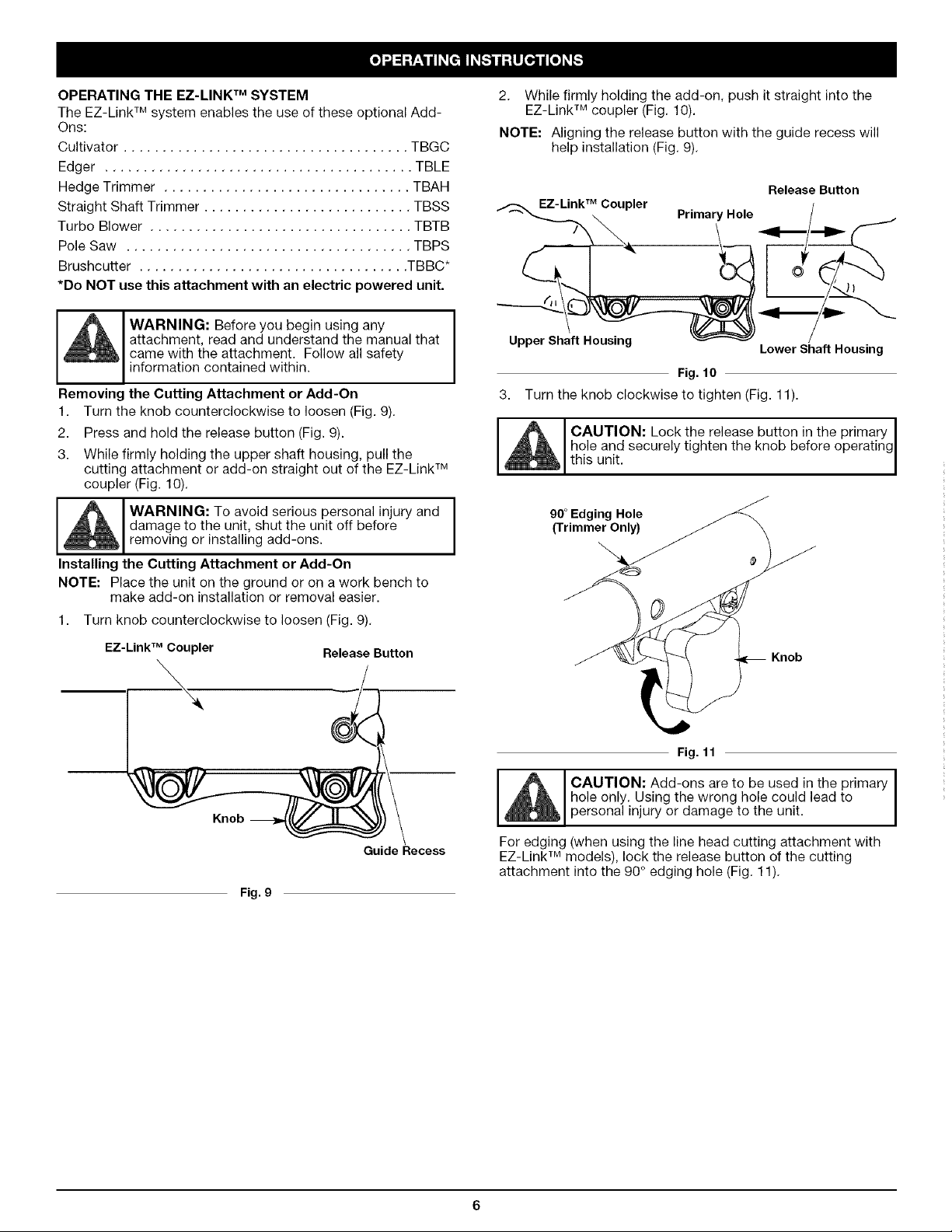
2. While firmly holding the add-on, push it straight into the
EZ-Link TM coupler (Fig. 10).
NOTE: Aligning the release button with the guide recess will
help installation (Fig. 9).
Release Button
EZ-Link TM Coupler
Upper Shaft Housing
3. Turn the knob clockwise to tighten (Fig. 11).
CAUTION: Lock the release button in the primary I
hole and securely tighten the knob before operating
this unit.
Primary Hole
Lower Shaft Housing
Fig.10
WARNING: To avoid serious personal injury and
damage to the unit, shut the unit off before
removtng or installing add-ons.
Installing the Cutting Attachment or Add-On
NOTE: Place the unit on the ground or on a work bench to
make add-on installation or removal easier.
1. Turn knob counterclockwise to loosen (Fig. 9).
EZ-LinkTM Coupler Release Button
Guide Recess
Fig. g
90° Edging Hole
(Trimmer Only)
Knob
Fig. 11
hole only. Using the wrong hole could lead to
CAUTION: Add-ons are to be used in the primary I
personal injury or damage to the unit.
For edging (when using the line head cutting attachment with
EZ-Link TM models), lock the release button of the cutting
attachment into the 90° edging hole (Fig. 11).
I
I
Page 7
HOLDING THE TRIMMER
WARNING: Always wear eye, hearing, foot and
body protection to reduce the risk of injury when
operating this unit.
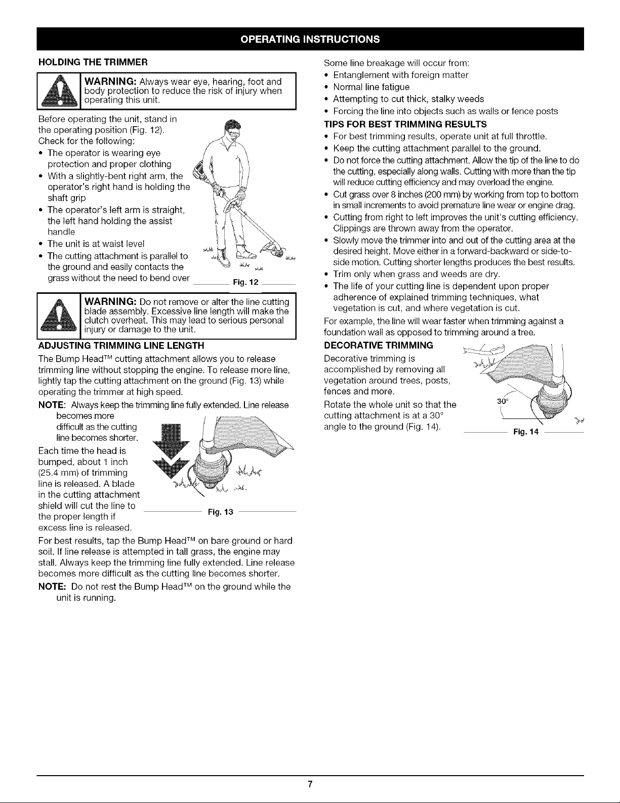
Before operating the unit, stand in
the operating position (Fig. 12).
Check for the following:
• The operator is wearing eye
protection and proper clothing
• With a slightly-bent right arm, the
operator's right hand is holding the
shaft grip
• The operator's left arm is straight,
the left hand holding the assist
handle
• The unit is at waist level
• The cutting attachment is parallel to
the ground and easily contacts the
grass without the need to bend over
Fig. 12
WARNING: Do not remove or alter the line cutting
blade assembly. Excessive line length will make the
clutch overheat, This may lead to serious personal
injury or damage to the unit.
ADJUSTING TRIMMING LINE LENGTH
The Bump Head TM cutting attachment allows you to release
trimming line without stopping the engine. To release more line,
lightly tap the cutting attachment on the ground (Fig. 13) while
operating the trimmer at high speed.
NOTE: Always keep the trimming line fully extended. Line release
becomes more
difficult as the cutting
linebecomes shorter.
Each time the head is
bumped, about 1 inch
(25.4 mm) of trimming
line is released. A blade .,_+
in the cutting attachment
shield will cut the line to
the proper length if Fig. 13
excess line is released.
For best results, tap the Bump Head TM on bare ground or hard
soil. If line release is attempted in tall grass, the engine may
stall. Always keep the trimming line fully extended. Line release
becomes more difficult as the cutting line becomes shorter.
NOTE: Do not rest the Bump Head TM on the ground while the
unit is running.
Some line breakage will occur from:
• Entanglement with foreign matter
• Normal line fatigue
• Attempting to cut thick, stalky weeds
• Forcing the line into objects such as walls or fence posts
TIPS FOR BEST TRIMMING RESULTS
• For best trimming results, operate unit at full throttle.
• Keep the cutting attachment parallel to the ground.
• Do not force the cutting attachment. Allow the tip of the line to do
the cutting, especially along walls. Cutting with more than the tip
will reduce cutting efficiency and may overload the engine.
• Cut grass over 8 inches (200 mm) by working from top to bottom
in small increments to avoid premature linewear or engine drag.
• Cutting from right to left improves the unit's cutting efficiency.
Clippings are thrown away from the operator.
• Slowly move the trimmer into and out of the cutting area at the
desired height. Move either in a forward-backward or side-to-
side motion. Cutting shorter lengths produces the best results.
• Trim only when grass and weeds are dry.
• The life of your cutting line is dependent upon proper
adherence of explained trimming techniques, what
vegetation is cut, and where vegetation is cut.
For example, the line will wear faster when trimming against a
foundation wall as opposed to trimming around a tree.
DECORATIVE TRIMMING
Decorative trimming is
accomplished by removing all
vegetation around trees, posts, x
fences and more.
Rotate the whole unit so that the
cutting attachment is at a 30+
angle to the ground (Fig. 14).
Fig. 14
Page 8

WARNING: To prevent serious injury, never
perform maintenance or repairs with unit running.
Always service and repair a cool unit. Disconnect the
spark plug wire to ensure that the unit cannot start.
MAINTENANCE SCHEDULE
Perform these required maintenance procedures at the
frequency stated in the table. These procedures should also be
a part of any seasonal tune-up.
NOTE: Some maintenance procedures may require special
tools or skills. If you are unsure about these
procedures take your unit to any non-road engine
repair establishment, individual or authorized service
NOTE: Maintenance, replacement, or repair of the emission
control devices and system may be performed by any
non-road engine repair establishment, individual or
authorized service dealer.
In order to assure peak performance of your engine, inspection
of the engine exhaust port may be necessary after 50 hours of
operation. If you notice lost RPM, poor performance or general
lack of acceleration, this service may be required. If you feel
your engine is in need of this inspection, refer service to any
non-road engine repair establishment, individual or authorized
service dealer for repair. DO NOT attempt to perform this
process yourself as engine damage may result from
contaminants involved in the cleaning process for the port.
dealer.
FREQUENCY MAINTENANCE REQUIRED SEE
Before starting engine Fill fuel tank with fresh fuel p. 4
Check oil p. 9
Every 10 hours Clean and re-oil air filter p. 10
1st change at 10 hours Change oil p. 10
2nd change at 25 hours Change oil p. 10
Every 25 hours after Clean spark arrestor p. 13
10 hours on new engine Check rocker arm to valve clearance and adjust p. 11
Every 25 hours Check rocker arm to valve clearance and adjust p. 11
Every 25 hours Check spark plug condition and gap p. 12
3.
Pull old line out of the line Trimming
i_ WARNING: Never use metal-reinforced line, wire,
chain or rope. These can break off and become
dangerous projectiles.
SPEEDSPOOL ® LINE INSTALLATION
Always use original equipment manufacturer 0.095 inch
(2.41 ram) replacement line. Lines other than those specified
may make the engine overheat or fail.
There are two methods to replace the SpeedSpool® trimming
line:
• Wind the inner reel with new line
• Install a pre-wound inner reel
Winding the Inner Reel With New Line
NOTE: It Is unnecessary to remove the bump knob to install a
new trimming line.
1. Cut two pieces of Top View Of The SpeedSpool®
0.095 inch
(2.41 mm)
Outer Spool
Arrows
trimming line, 10
feet (3 m) long.
2. Hold the outer
spool and turn the
loading and line locking holes
(Fig. 17 and 18).
4.
Insert a piece of trimming line
straight into one of the two
eyelets in the outer spool.
Push it up through the line
loading hole in the inner reel
(Fig. 16). Do not bend the line
when inserting it into the
eyelet.
5.
Insert the line into the locking
hole (Fig. 17). Do not push the Fig. 16
line more than a 1/2 inch (12.7
ram) into the line locking hole. The line will form a small
loop (Fig. 17) when it is inserted correctly.
6.
Pull the line from the outer spool until the line is tight
against the inner reel (Fig. 18).
7.
Repeat procedures 4-6 with the second piece of line.
8.
Hold the outer spool. Wind the inner reel counterclockwise
until approximately four (4) inches (102 mm) of line remain
(Fig. 19).
inner reel
counterclockwise
to line up the
arrows on the
outer spool and
inner reel (Fig. 15).
Knob
Fig. 15
WARNING: Always use the correct line length
when installing trimming line on the unit. The line
may not release properly if the line is too long.
Line Locking Hole
Fig. 17 Fig. 18
Page 9

If winding the line becomes
difficult or if the line jams,
pull the ends of the line from
the spool (Fig. 19). Continue
winding the inner reel
counterclockwise until
approximately 6 inches of
line is left.
INSTALLING A PRE-WOUND
REEL
1. Turn the bump knob
counterclockwise and
remove the bump knob,
spring and foam seal
(Fig. 20).
2. Pull the old inner reel
with existing line from
the outer spool.
3. Insert the ends of the
prewound inner reelline
into the outer spool eyelets (Fig. 21).
Push the new inner reel, arrow side
up, into the outer spool.
4. Hold the inner reelin place and
install the bump knob, spring and
foam seal (Fig. 22). Press down and
turn the bump knob clockwise.
Grasp the ends and pull firmly to
release the line from the holding slots
in the inner reel.
Releasing the Inner Reel
Ifthe SpeedSpool ® does not
release line correctly, pull the
ends of the line firmly from the
spool (Fig. 18). If this does not
the release line, follow the
Cleaning the SpeedSpool ®
instructions.
NOTE: Do not wind the inner
reel before installing
the second piece of
line.
CLEANING THE
SPEEDSPOOL ®
Cleaning the SpeedSpool ® may
be necessary if:
• A jammed or excessive line must be removed
• The SpeedSpool ® becomes difficult to wind or does not
operate correctly when bumping the head on the ground
1. Hold the outer spool, and unscrew the bump knob
counterclockwise (Fig. 23).
2. Pull out the bump knob, spring and foam
seal (Fig. 22).
3. Pull the inner reel with existing line from the
outer spool (Fig.24).
4. Remove any existing line from the inner
reel before cleaning. Remove any debris or
grass from the knob, spring, inner reel and
foam seal. Wash the inner reel with warm
soapy water (Fig. 24). Fig,23
5. Clean the shaft and the inner surface of the outer spool. To
clean the shaft underneath the plunger, press down on the
plunger (Fig. 25). Remove any dirt or debris from the shaft.
z
Bump Knob
Foam Seal
Spring
Inner Reel _
Fig. 19
Fig. 20
\
Fig. 21
Fig. 22
NOTE: The inner reel must be totally
dry before reinstalling it into
the outer spool. Do not
lubricate the inner reel or
outer spool assembly.
6. Place the inner reel into the outer
spool.
7. Place the bump knob, spring
and foam seal into the inner reel
(Fig. 22).
8. Press the bump knob down and
tighten clockwise.
9. Install new line as
described in Line
Installation for the
SpeedSpool ®.
CHECKING THE OIL LEVEL
The importance of checking
and maintaining the proper
oil level in the crankcase
cannot be overemphasized.
Check oil before each use:
1.
Stop the engine and allow oil to drain into the crankcase.
2.
Place the engine on a flat, level surface with the cutting
head shield hanging off a work bench or table to get a
proper oil level reading (Fig. 26).
f
Shaft. J" /
Plunger _X.f _ f
Inner Reel
Fig.24
Fig. 25
1
Fig.26
3. Keep dirt, grass clippings and other debris out of the engine.
Clean the area around the dipstick before removing it.
4. Remove the oil fill plug.
5. Look into the oil fill hole, use a flashlight if needed. The oil
should be just touching the inner most thread (Fig. 27).
6. Ifthe oil level is not touching the inner most thread on the
oil fill hole, add a small amount of oil to the oil fill hole and
recheck (Fig. 27). Repeat this procedure until the oil level
reaches the inner most thread on the oil fill hole.
NOTE: Do not overfill the unit.
NOTE: Make sure the O-ring is in place on the oil fill plug when
checking and changing the oil (Fig. 28).
\v _/ OilFill Plug I/__
MaxOil Fill Line
Fig.27 _ Fig.28
-,ng
Page 10

CHANGING THE OIL
For a new engine, change the oil after the first 10 hours of
operation. Change the oil while the engine is still warm. The oil will
flow freely and carry away more impurities.
1. Unplug spark plug boot to prevent accidental starting.
WARNING: Wear gloves to prevent injury when
handling unit.
2.
Remove the oil fill plug.
3. Pour the oil out of the
oil fill hole and into a
container by tipping the
unit to a vertical
position (Fig. 29). Allow
ample time for
complete drainage.
4. Wipe up any oil residue
on the unit and clean
up any oil that may
have spilled. Dispose of
the oil according to
Federal, State and local
regulations.
5. Refill the crankcase Fig. 29
with 3.04 fluid ounce
(90 ml) of SAE 30 SF, SG, SH oil.
NOTE: Use the bottle and spout saved from initial use to measure
the correct amount of oil. The top of the label on the bottle
measures approximately 3.04 ounces (90 ml) (Fig. 30). Check
the level, See Checking the OilLevel. If the level is low, add a
small amount of oil and recheck. Do not overfill (Fig. 30).
Air Filter Cover
Fig. 31
2. Remove the air filter (Fig. 31).
3. Wash the filter in detergent and
water (Fig. 32). Rinse the filter
thoroughly and allow it to dry.
4. Apply enough clean SAE 30
motor oil to lightly coat the filter
(Fig. 33).
5. Squeeze the filter to spread and
remove excess oil (Fig. 34).
6. Replace the filter (Fig. 31).
NOTE: If the unit is operated
without the air filter, you will
VOID the warranty.
Tab
f
\
Fig.32
FillLevel
\
Fig.30
6. Replace the oil fill plug.
7. Reconnect the spark plug boot.
AIR FILTER MAINTENANCE
_1 WARNING: To avoid serious personal injury,
Cleaning the Air Filter
Clean and re-oil the air filter every 10 hours of operation. It is
an important item to maintain. Failure to maintain your air filter
properly can result in poor performance or can cause
permanent damage to your engine.
1. Open the air filter cover. Push the tab on the under side of
always turn the unit off and allow it to cool before
you clean or service it.
the cover inward. Then pull the air filter cover out and up.
(Fig. 31).
Fig. 33
Fig. 34
7. Reinstall the air filter cover. Position the slots on the top of
the air filter cover onto the tabs at the top of the back plate
(Fig. 35).
8. Swing the cover down until the tab on the air filter backplate
snaps into place in the slot on the air filter cover (Fig. 36).
Back Plate
Tabs
Air _r__
Locking Tab
Fig. 35
10
Page 11

Air Filter Cover
Tab
Fig. 36
CARBURETOR ADJUSTMENT
The idle speed of the engine is adjustable. An idle adjustment
screw is between the air filter cover and the engine starter
housing (Fig. 37).
NOTE: Careless Idle Adjustment Screw
adjustments can f
seriously damage your
unit. An authorized
service dealer should
make carburetor
adjustments.
Check Fuel
Old fuel is usually the
reason for improper unit
performance. Drain and
refill the tank with fresh fuel Fig.37
prior to making any adjustments. Refer to Oil and Fuel
Information.
Clean Air Filter
The condition of the air filter is important to the operation of the
unit. A dirty air filter will restrict air flow. This is often mistaken
for an out of adjustment carburetor. Check the condition of the
air filter before adjusting the idle speed screw. Refer to Air
Filter Maintenance.
Adjust Idle Speed Screw
Checking the fuel, cleaning the air filter, and adjusting the idle
speed should solve most engine problems. If not and all of the
following are true:
• the engine will not idle
• the engine hesitates or stalls on acceleration
• there is a loss of engine power
Have the carburetor adjusted by an authorized service dealer.
ROCKER ARM CLEARANCE
This requires disassembly of the engine. If you feel unsure or
unqualified to perform this, take the unit to an authorized
service center.
NOTE: Inspect the valve to rocker arm clearance with a feeler
gauge after the first 10 hours of operation and every 25
hours of operation.
• The engine must be cold when checking or adjusting the
valve clearance.
• This task should be performed inside, in a clean, dust free
area.
1. Remove the six (6) screws on the back of the engine cover
with a Flat-head or T-25 Torx screwdriver (Fig. 38).
2. Disconnect the spark plug wire.
3. Clean dirt from around the spark plug. Remove the spark
plug from the cylinder head by turning a 5/8 in. socket
counterclockwise.
4. Remove the engine cover (Fig. 38).
View Of The Rear Engine Cover
Remove
Screws
WARNING: To prevent serious personal injury,
make sure the cutting attachment has stopped
rotating before you turn it off and set it down.
If, after checking the fuel and cleaning the air filter, the engine
still will not idle, adjust the idle speed screw as follows:
1. Start the engine and let it run at a high idle for a minute to
warm up. Refer to Starting/Stopping Instructions.
2. Release the throttle trigger and let the engine idle. Ifthe
engine stops, insert a small phillips in between the Air Filter
Cover and the Engine Cover (Fig. 48). Turn the idle speed
screw in, clockwise, 1/8 of a turn at a time (as needed) until
the engine idles smoothly.
NOTE: The cutting attachment should not rotate when the
engine idles.
3. If the cutting attachment rotates when the engine idles, turn
the idle speed screw counterclockwise 1/8 of a turn at a
time (as needed), to reduce idle speed.
WARNING: The cutting attachment may spin during
idle speed adjustments. Wear protective clothing and
observe all safety instructions to prevent serious
personal injury.
Fig. 38
Clean dirt from around the rocker arm cover. Remove the
screw holding the rocker arm cover with a large flat blade
screwdriver or Torx T-25 bit (Fig. 39). Remove the rocker
arm cover and gasket.
Pullthe starter rope slowly to I
bring the piston to the top of its Rocker i I
travel, (known as top dead
center). Check that:
The piston is at the top of its
travel while looking in the
spark plug hole (Fig. 40)
Both rocker arms move
freely, and both valves are
Fig. 39
11
Page 12

closed
Ifthesestatementsarenottrue,repeatthisstep.
7. Slidethefeelergaugebetweentherockerarmandthe
valvereturnspring.Measuretheclearancebetweenthe
Adjusting Nut
Rocker Arm
Rocker Arms INTAKE
Nuts
EXHAUST
@
Feeler Gauge / (_
Spark Plug
Hole
Fig. 40
valve stem and rocker arm (Fig. 40). Measure both the
intake and exhaust valves.
The recommended clearance for both intake and exhaust is
.003 - .006 in. (.076 - 0.152 mm). Use a standard automotive
.005 in. (0.127 mm) feeler gauge. The feeler gauge should slide
between the rocker arm and valve stem with a slight amount of
resistance, without binding. See Figures 40 and 41.
8. If the clearance is not within specification:
a. Turn the adjusting nut using a 5/16 inch (8 mm) wrench or
nut driver (Fig. 40).
• To increase clearance, turn the adjusting nut
counterclockwise.
• To decrease clearance, turn the adjusting nut
clockwise.
b. Recheck both clearances, and adjust as necessary.
9. Reinstall the rocker arm cover using a new gasket. Torque
the screw to 20-30 in•lb (2.2-3.4 Nom).
10. Check the spark plug and reinstall. See Replacing the
Spark Plug.
11. Replace the spark plug wire.
.003-.006 in.
(.076-.152 mm) --
Feele!Gauge
Valve Stem
Fig. 41
12. Reinstall the engine cover. Check alignment of the cover
before tightening the screws. Tighten screws.
REPLACING THE SPARK PLUG
Use a replacement part number 753-05255 spark plug. The
correct air gap is 0.025 in. (0.655 mm.). Remove the plug after
every 25 hours of operation and check its condition.
1. Stop the engine and allow it to cool. Remove the six (6)
screws on the back of the engine cover with a Flat-head or
T-25 Torx screwdriver (Fig. 38).
2. Grasp the plug wire firmly and pull the cap from the spark
plug.
3. Clean dirt from around the
spark plug. Remove the
spark plug from the cylinder
head by turning a 5/8 in. 0.025 in.
socket counterclockwise. (0.655 mm.)
4. Replace cracked, fouled or ,L
dirty spark plug. Set the air
gap at 0.025 in. (0.655 mm.)
using a feeler gauge (Fig. 42).
5. Install a correctly-gapped Fig. 42
spark plug in the cylinder head. Turn the 5/8 in. socket
clockwise until snug.
If using a torque wrench torque to:
u
T
H
12
WARNING: Do not sand blast, scrape or clean I
electrodes. Grit in the engine could damage the
cylinder.
I
I
Page 13

SPARK ARRESTOR MAINTENANCE
1. Remove the rear engine cover. See RockerArm Clearance.
2. With a flat blade screwdriver or Torx T-20 bit and a T-25
bit, remove the screws attaching the spark arrestor cover
to the muffler (Fig. 43).
Muffler
Spark Arrestor Screen
Diverter
T-25 Screw
Slot
ql_ T-20 Screw
Fig. 43
3,
Pull the tab on the spark arrestor cover out of the muffler.
Remove the spark arrestor cover.
4.
Remove the spark arrestor screen from the spark arrestor
cover.
5.
Clean the spark arrestor screen with a wire brush or
replace it.
6.
Reinstall the spark arrestor screen, spark arrestor cover
and screws.
WARNING: To avoid serious personal injury,
always turn your unit off and allow it to cool before
you clean or service it.
LONG TERM STORAGE
1. Drain all gasoline from the gas tank into a container. Do
not use gas that has been stored for more than 60 days.
Dispose of the old gasoline in accordance to Federal,
State, and Local regulations.
2. Start the engine and allow it to run until it stalls. This
ensures that all gasoline has been drained from the
carburetor.
3. Allow the engine to cool. Remove the spark plug and put 1
oz. (30 ml) of high quality motor oil into the cylinder. Pull
the starter rope slowly to distribute the oil. Reinstall the
spark plug.
NOTE: Remove the spark plug and drain all of the oil from the
cylinder before attempting to start the trimmer after
storage.
4. Change the oil, referring to Changing the Oil. Dispose of
the old oil in accordance to Federal, State and Local
regulations.
5. Thoroughly clean the unit and inspect for any loose or
damaged parts. Repair or replace damaged parts and
tighten loose screws, nuts or bolts. The unit is ready for
storage.
TRANSPORTING
• Allow the engine to cool before transporting.
• Securethe unit while transporting.
• Drain the gas tank before transporting.
• Tighten gas cap before transporting.
CLEANING
Use a small brush to clean off the outside of the unit. Do not
use strong detergents. Household cleaners that contain
aromatic oils such as pine and lemon, and solvents such as
kerosene, can damage plastic housing or handle. Wipe off any
moisture with a soft cloth.
STORAGE
• Never store the unit with fuel in the tank where fumes may
reach an open flame or spark.
• Allow the engine to cool before storing.
• Lock up the unit to prevent unauthorized use or damage.
• Store the unit in a dry, well-ventilated area.
• Store the unit out of the reach of children.
13
Page 14

CAUSE
On/OffcontrolintheSTOPposition
Emptyfueltank
Primerbulbwasn'tpressedenough
Oldfuel
Fouledsparkplug
Pluggedsparkarrestor
ACTION
TurnOn/OffcontroltoON
Fillfueltankwithnewfuel
Pressprimerbulbfullyandslowly10times
Draingastankandaddfreshfuel
Replaceorcleanthesparkplug
Cleanorreplacesparkarrestor
CAUSE
Airfilterisplugged
Oldfuel
Impropercarburetoradjustment
CAUSE
Oldfuel
Impropercarburetoradjustment
Cuttingattachmentboundwithgrass
Dirtyairfilter
Pluggedsparkarrestor
CAUSE
Oldfuel
Impropercarburetoradjustment
Fouledsparkplug
Pluggedsparkarrestor
CAUSE
Cuttingattachmentboundwithgrass
Cuttingattachmentoutofline
Innerreelboundup
Cuttingheaddirty
Linewelded
Linetwistedwhenrefilled
Notenoughlineisexposed
ACTION
Replaceorcleantheairfilter
Draingastankandaddfreshfuel
Adjustcarburetor
ACTION
Draingastankandaddfreshfuel
Taketoanauthorizedservicedealerforadjustment
Stoptheengineandcleanthecuttingattachment
Cleanorreplacetheairfilter
Cleanorreplacesparkarrestor
ACTION
Draingastankandaddfreshfuel
Taketoanauthorizedservicedealerforadjustment
Replaceorcleanthesparkplug
Cleanorreplacesparkarrestor
ACTION
Stoptheengineandcleancuttingattachment
Refillwithnewline
Replacetheinnerreel
Cleaninnerreelandouterspool
Disassemble,removetheweldedsectionandrewind
Disassembleandrewindtheline
Pushthebumpknobandpulloutlineuntil4inches(102mm)
oflineisoutsideofthecuttingattachment
CAUSE
Oil,cleanerorlubricantincuttinghead
If further assistance is required, contact your authorized service dealer.
ACTION
Cleanandthoroughlydrythecuttinghead
14
Page 15

Engine Type ......................................................................................................................................................................................... Air-Cooled, 4-Cycle
Displacement ............................................................................................................................................................................................ 1.8 cu. in. (29 cc)
Operating RPM ................................................................................................................................................................................................... 6,800+ rpm
Idle Speed RPM ...................................................................................................................................................................................... 2,800 - 3,600 rpm
Ignition Type ......................................................................................................................................................................................................... Electronic
Ignition Switch ............................................................................................................................................................................................... Rocker Switch
Valve clearance .............................................................................................................................................................. 0.003-0.006 in. (0.076-0.152 mm)
Spark Plug Gap ................................................................................................................................................................................ 0.025 inch (0.655 mm)
Lubrication ........................................................................................................................................................................................................... SAE 30 Oil
Crankcase Oil Capacity ................................................................................................................................................................................ 3.04 oz (90 ml)
Fuel ....................................................................................................................................................................................................................... Unleaded
Carburetor ....................................................................................................................................................................................... Diaphragm, All-Position
Starter ............................................................................................................................................................................................................... Auto Rewind
Muffler ..................................................................................................................................................................................................... Baffled with Guard
Throttle ............................................................................................................................................................................................... Manual Spring Return
Fuel Tank Capacity ......................................................................................................................................................................................... 14 oz (414 ml)
Drive Shaft Housing .......................................................................................................................................................................... Steel Tube (EZ-Link TM)
Throttle Control ........................................................................................................................................................................................ Finger-Tip Trigger
Approximate Unit Weight (No fuel, with handle, cutting attachment and shield) ........................................................................ 11.5-13.0 Ibs (5.2-5.9 kg)
Cutting Mechanism ........................................................................................................................................................................................ SpeedSpool®
Line Spool ............................................................................................................................................................................................. Bump Line Releaser
Line Spool Diameter ............................................................................................................................................................................ 4 inches (101.6 mm)
Trimming Line Diameter .................................................................................................................................................................... 095 inches (2.41 mm)
Cutting Path Diameter, Trimmer Head ................................................................................................................................................. 17 inches (43.2 cm)
*All specifications are based on the latest product information available at the time of printing. We reserve the right to make changes
at any time without notice.
15
Page 16

16
Page 17

California / EPA Emission Control Warranty Statement
Your Warranty Rights and Obligations
The California Air Resources Board, the Environmental Protection Agency and Troy-Bilt LLC (Troy-Bilt) are pleased to explain the
emission control system warranty on your 2005 and later small off-road engine. New small off-road engines must be designed, built
and equipped to meet stringent anti-smog standards. Troy-Bilt must warrant the emission control system on your small off-road
engine for the periods of time listed below provided there has been no abuse, neglect or improper maintenance of your small off-road
engine.
Your emission control system may include parts such as the carburetor or fuel-injected system, the ignition system, and catalytic
converter. Also included may be hoses, belts, connectors and other emission-related assemblies.
Where a warrantable condition exists, Troy-Bilt will repair your small off-road engine at no cost to you including diagnosis, parts and
labor.
The 2005 and later small off-road engines are warranted for two years. If any emission-related part on your engine is defective, the
part will be repaired or replaced by Troy-Bilt.
Owners Warranty Responsibilities
• As the small off-road engine owner, you are responsible for the performance of the required maintenance listed in your operator's
manual. Troy-Bilt recommends that you retain all receipts covering maintenance on your small off-road engine, but Troy-Bilt cannot
deny warranty solely for the lack of receipts or for your failure to ensure the performance of all scheduled maintenance.
• As the small off-road engine owner, you however should be aware that Troy-Bilt may deny you warranty coverage if your small off-
road engine or a part has failed due to abuse, neglect, improper maintenance or unapproved modifications.
• You are responsible for presenting your small off-road engine to a Troy-Bilt Authorized Service Center as soon as a problem exists.
The warranty repairs should be completed in a reasonable amount of time, not to exceed 30 days.
Ifyou have any questions regarding your warranty rights and responsibilities, you should call 1-800-520-5520.
Manufacturer's Warranty Coverage
• The warranty period begins on the date the engine or equipment is delivered to the retail purchaser.
• The manufacturer warrants to the initial owner and each subsequent purchaser, that the engine is free from defects in material and
workmanship which cause the failure of a warranted part for a period of two years.
• Repair or replacement of warranted part will be performed at no charge to the owner at an Authorized Troy-Bilt Service Center. For
the nearest location please contact Troy-Bilt at: 1-800-520-5520.
• Any warranted part which is not scheduled for replacement, as required maintenance or which is scheduled for only for regular
inspection to the effect of "Repair or Replace as Necessary" is warranted for the warranty period. Any warranted part which is
scheduled for replacement as required maintenance will be warranted for the period of time up to the first scheduled replacement
point for that part.
• The owner will not be charged for diagnostic labor which leads to the determination that a warranted part is defective, if the
diagnostic work is performed at an Authorized Troy-Bilt Service Center.
• The manufacturer is liable for damages to other engine components caused by the failure of a warranted part still under warranty.
• Failures caused by abuse, neglect or improper maintenance are not covered under warranty.
• The use of add-on or modified parts can be grounds for disallowing a warranty claim. The manufacturer is not liable to cover failures
of warranted parts caused by the use of add-on or modified parts.
• In order to file a claim, go to your nearest Authorized Troy-Bilt Service Center. Warranty services or repairs will be provided at all
Authorized Troy-Bilt Service Centers.
• Any manufacturer approved replacement part may be used in the performance of any warranty maintenance or repair of emission
related parts and will be provided without charge to the owner. Any replacement part that is equivalent in performance or durability
may be used in non-warranty maintenance or repair and will not reduce the warranty obligations of the manufacturer
• The following components are included in the emission related warranty of the engine, air filter, carburetor, primer, fuel lines, fuel
pick up/fuel filter, ignition module, spark plug and muffler.
17
Page 18

MANUFACTURER'S LIMITED WARRANTY FOR:
®
The limited warranty set forth below is given by Troy-Bilt
LLC with respect to new merchandise purchased and used
in the United States, its possessions and territories.
Troy-Bilt LLC warrants this product against defects in
material and workmanship for a period of two (2) years
commencing on the date of original purchase and will, at its
option, repair or replace, free of charge, any part found to
be defective in material or workmanship. This limited
warranty shall only apply if this product has been operated
and maintained in accordance with the Operator's Manual
furnished with the product, and has not been subject to
misuse, abuse, commercial use, neglect, accident,
improper maintenance, alteration, vandalism, theft, fire,
water or damage because of other peril or natural disaster.
Damage resulting from the installation or use of any
accessory or attachment not approved by Troy-Bilt LLC for
use with the product(s) covered by this manual will void
your warranty as to any resulting damage. This warranty is
limited to ninety (90) days from the date of original retail
purchase for any Troy-Bilt product that is used for rental or
commercial purposes, or any other income-producing
purpose.
HOW TO OBTAIN SERVICE: Warranty service is
available, WITH PROOF OF PURCHASE THROUGH
YOUR LOCAL AUTHORIZED SERVICE DEALER. To locate
the dealer in your area, visit our website at www.troybilt.com,
check for a listing in the Yellow Pages, call 1-800-520-
5520 or write to P.O. Box 361131, Cleveland, OH 44136-
0019.
This limited warranty does not provide coverage in
the following cases:
A. Tune-ups - Spark Plugs, Carburetor Adjustments,
Filters
B. Wear items - Bump Knobs, Outer Spools, Cutting Line,
InnerReels, Starter Pulley,Starter Ropes, Drive Belts
C. Troy-Bilt LLC does not extend any warranty for
products sold or exported outside of the United
States of America, its possessions and territories,
except those sold through Troy-Bilt's authorized
channels of export distribution.
Troy-Bilt LLC reserves the right to change or improve the
design of any Troy-Bilt Product without assuming any
obligation to modify any product previously manufactured.
No implied warranty, including any implied warranty of
merchantability or fitness for a particular purpose,
applies after the applicable period of express written
warranty above as to the parts as identified. No other
express warranty or guaranty, whether written or oral,
except as mentioned above, given by any person or
entity, including a dealer or retailer, with respect to any
product shall bind Troy-Bilt LLC During the period of
the Warranty, the exclusive remedy is repair or
replacement of the product as set forth above. (Some
states do not allow limitations on how long an implied
warranty lasts, so the above limitation may not apply to
you.)
The provisions as set forth in this Warranty provide the
sole and exclusive remedy arising from the sales.
Troy-Bilt LLC shall not be liable for incidental or
consequential loss or damages including, without
limitation, expenses incurred for substitute or
replacement lawn care services, for transportation or
for related expenses, or for rental expenses to
temporarily replace a warranted product. (Some states
do not allow limitations on how long an implied warranty
lasts, so the above limitation may not apply to you.)
In no event shall recovery of any kind be greater than the
amount of the purchase price of the product sold.
Alteration of the safety features of the product shall void
this Warranty. You assume the risk and liability for loss,
damage, or injury to you and your property and/or to
others and their property arising out of the use or misuse
or inability to use the product.
This limited warranty shall not extend to anyone other than
the original purchaser, original lessee or the person for
whom it was purchased as a gift.
How State Law Relates to this Warranty: This warranty
gives you specific legal rights, and you may also have
other rights which vary from state to state.
To locate your nearest service dealer dial 1-800-520-5520.
Troy-Bilt LLC
P.O. Box 361131
Cleveland, OH 44136-0019
18
Page 19

REPLACEMENT PARTS - MODELS TB575SS & TB525CS
4-CYCLE GAS TRIMMER
El8
Page 20

REPLACEMENT PARTS - MODELS TB575SS & TB525CS
4-CYCLE GAS TRIMMER
Item Part No. Description Item Part No.
1 753-05206 Engine Cover Assembly (includes 2 & 3) 30 791-181751
2 753-04595 Cover Screw 31 753-05252
3 753-05208 Screw 32 753-05254
4 753-05209 Rocker Cover 33 753-05253
5 753-05210 Rocker Cover O-Ring 34 753-05256
6 753-05228 Cylinder Assembly (includes 3, 5 & 9) 35 753-1229
7 753-05229 Piston Ring Assembly 36 753-05259
8 753-05230 Piston Assembly (includes 7) 37 753-05260
9 753-05232 Cylinder O-Ring 38 753-1202
10 791-182379 Breather Hose 39 753-05074
11 753-05236 Oil Plug (includes 12) 40 753-05078
12 791-182290 Oil Plug O-Ring 41 753-05261
13 753-05237 Crankcase Cover 42 791-613103
14 753-05238 Crankcase Cover O-ring 43 753-04286
15 753-05239 Crankcase Assembly (includes 9, 10 & 14) 44 791-181079
16 753-05240 Flywheel Assembly 45 791-611061
17 753-05241 Cam Bracket Assembly (includes 18) 46 753-05262
18 753-05242 Cam Bracket Screw 47 791-182396
19 753-05264 Lead Wires 48 753-1238
20 753-05243 Module Assembly 49 791-153592
21 753-05244 Muffler Gasket 50 753-05263
22 753-05245 Muffler Assembly (includes 21 & 23) 51 791-182519
23 753-05246 Muffler Screw 52 753-04003
24 753-05255 Spark Plug 53 791-180217
25 753-05247 Insulator Gasket 753-05297
26 753-05248 Nut 753-05265
27 753-05249 Insulator
28 753-05250 Carburetor Gasket
29 753-05251 Carburetor w/Primer
Description
O-Ring
Air Cleaner Cover Assembly (includes 32)
Air Filter
Screw
Fuel Tank Assembly w/Fuel Lines (includes 35)
Fuel Cap
Fuel Tank Pads
Push Nut
Pressure Plate Screw
Pressure Plate (includes 38)
Spacer
Starter Assembly (includes 42)
Rope
Recoil Spring
Handle
Rope Guide
Starter Housing Assembly (includes 3 & 37-45)
Washer
Clutch & Clutch Washer
Clutch Drum
Clutch Cover
Anti-Rotation Screw
Clamp Screw
Nut
Spark Arrestor Assembly
Shortblock Assembly
(includes 3-12, 14, 15, 17 & 24)
E19
Page 21

Item
1
2
3
4
5
6
7
8
9
10
11
12
13
14
15
16
17
18
19
20
21
22
23
24
25
26
27
28
29
30
31
32
33
34
35
36
Part No.
753-04234
753-04119
791-182690
791-182405
753-05266
753-04236
791-180869
791-181070
791-182167
791-182168
753-1190
791-182057
791-181617
791-181981
753-04386
753-04504
753-05267
791-153597
791-145569
753-05269
791-180547
753-1213
791-181823
791-181457
791-181458
791-181561
753-04257
791-181459
791-181532
791-181531
791-181462
791-181463
791-181464
791-181465B
791-181467
791-181468B
753-05268
Description
Throttle Housing Assembly (includes 2-4)
Throttle Trigger
Throttle Trigger Spring
Switch
Throttle Cable Assembly
Upper Drive Shaft Housing Assembly
Deluxe D-Handle Assembly (includes 8-10)
Screw
Deluxe D-Handle
Bottom Clamp
Split Boom Coupler (includes 12-15)
Screw
Bolt
Adjustment Knob (includes 15)
Knob Retaining Nut
Lower Drive Shaft Housing Assembly
Lower Flexible Drive Shaft
Lower Clamp Assembly (includes 19)
Anti-Rotation Screw
Gear Box Assembly (includes 24 & 25)
Shield Mounting Hardware
Shield Assembly (includes 23)
Blade Assembly
Outer Spool Assembly (includes 25)
Retainer
Thrust Washer
Slider
Small Spring
E-Clip
Spring
Plunger
C-Clip
Inner Reel
Large Spring
Foam Seal
Bump Head Knob Assembly (includes 34 & 35)
Cutting Head Assembly (18,19 & 24-36)
REPLACEMENT PARTS - MODELS TB575SS
4-CYCLE GAS TRIMMER
\\
@__I
Items Not Shown
E20
Page 22

®
Item Part No. Description
1 753-04234 Throttle Housing Assembly (includes 2-4)
2 791-182690 Throttle Trigger Spring
3 753-04119 Throttle Trigger
4 791-182405 Switch
5 753-05266 Throttle Cable Assembly
6 753-04236 Upper Drive Shaft Housing Assembly
7 791-180869 Deluxe D-Handle Assembly (includes 8-10)
8 791-181070 Screw
9 791-182167 Deluxe D-Handle
10 791-182168 Bottom Clamp
11 753-1190 Split boom Coupler (includes 12-15)
12 791-182057 Screw
13 791-181617 Bolt
14 791-181981 Adjustment Knob (includes 15)
15 753-04386 Knob Retaining Nut
16 791-182387 Lower Drive Shaft Housing Assembly (includes 18)
17 791-153597 Lower Clamp Assembly (includes 21)
18 791-181852 Lower Flexible Drive Shaft
19 791-180531 Shield Mounting Screw
20 791-181857 Bushing Housing Assembly
21 791-145569 Anti-Rotation Screw
22 791-181659 Shield Assembly (includes 23)
23 753-05212 Blade Assembly
24 791-181457 Outer Spool Assembly (includes 25)
25 791-181458 Retainer
26 791-181561 Thrust Washer
27 791-181459 Small Spring
28 753-04257 Slider
29 791-181532 E-Clip
30 791-181531 Spring
31 791-181462 Plunger
32 791-181463 C-Clip
33 791-181464 Inner Reel
34 791-181465B Large Spring
35 791-181467 Foam Seal
36 791-181468B Bump Head Knob Assembly (includes 34 & 35)
753-04929 Complete Cutting Head Assemly
(includes 17, 20, 21,24-36)
REPLACEMENT PARTS - MODELS TB525CS
4-CYCLE GAS TRIMMER
O_otional Accessorie
791-180120 ReplacementLine, 0.095"
Items Not Shown
E21
 Loading...