

Page 1
READ ALL INSTRUCTIONS BEFORE OPERATING
BASIC SAFETY PRECAUTIONS
• DO NOT rely exclusively upon the safety devices built into the unit.
• DO NOT allow the unit to be used as a toy.
• Please read the entire operator’s manual carefully before attempting to assemble, operate or
maintain the unit.
• Follow all safety instructions. Failure to do so can result in property damage or serious injury to
yourself and/or others.
• Be thoroughly familiar with the controls and the proper use of the unit. Know how to stop the unit
and disengage the controls quickly.
• Stay alert! Do not operate the unit when tired, ill or under the influence of alcohol, drugs or medication.
• Never allow children to operate the unit. Never allow adults to operate the unit without proper instruction.
• Make sure that all guards and safety attachments are properly installed before operating the unit.
• Keep these instructions. Refer to them often and use them to instruct other users. If loaning
someone this unit, also loan them these instructions.
• Keep bystanders, especially children and pets, at least 50 feet (15 m) away. If anyone enters the
work area, stop the unit!
• Keep the work area clean. Cluttered areas invite injuries. Do not start cutting until the work area is clear
and free from obstructions, there is secure footing and a planned retreat path from falling branches.
• Always wear appropriate eye and ear/hearing protection when operating this unit. Wear safety
goggles, or safety glasses with side shields, that are marked as meeting ANSI Z87.1-1989
standards. Failure to do so could result in serious eye injury caused by thrown or falling objects. If
the operation is dusty, wear a facemask or dust mask. Use a hard hat or other type of safety helmet.
• Dress appropriately, wear heavy, snug-fitting clothes (long pants and a long sleeve shirt), non-slip
protective gloves and steel-toed safety boots. Do not wear loose clothing, jewelry, short pants,
sandals or go barefoot. Secure hair above shoulder level to prevent entanglement in moving parts.
• Only use the unit in daylight or good artificial light.
• Only use the unit for its intended purpose: to cut wood. Only use the unit as described in this
manual. Only use the manufacturer’s recommended attachments with this unit.
• IMPORTANT SAFETY INSTRUCTIONS •
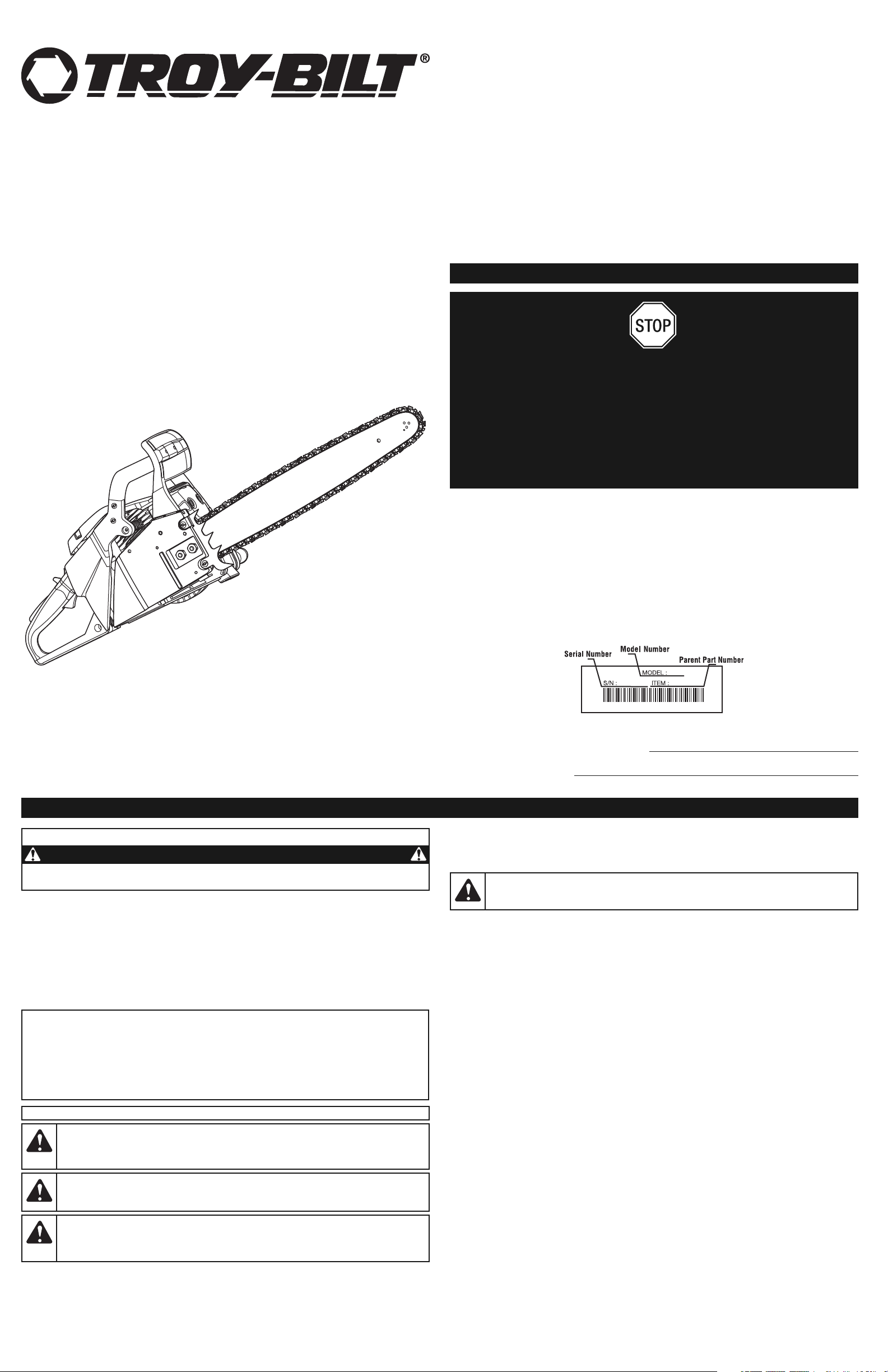
Operator’s Manual
55cc 2-Cycle Chain Saw
TB5518
TABLE OF CONTENTS
Service Information . . . . . . . . . . . . . . . . . . . . . . . . . . . . . . . . . . . . . . . . . . . . . . . . . . . . . . . . . . . . . .1
Safety Information . . . . . . . . . . . . . . . . . . . . . . . . . . . . . . . . . . . . . . . . . . . . . . . . . . . . . . . . . . . . . . .1
Know Your Unit . . . . . . . . . . . . . . . . . . . . . . . . . . . . . . . . . . . . . . . . . . . . . . . . . . . . . . . . . . . . . . . . .3
Assembly Instructions . . . . . . . . . . . . . . . . . . . . . . . . . . . . . . . . . . . . . . . . . . . . . . . . . . . . . . . . . . . .4
Oil and Fuel Information . . . . . . . . . . . . . . . . . . . . . . . . . . . . . . . . . . . . . . . . . . . . . . . . . . . . . . . . . .4
Starting and Stopping Instructions . . . . . . . . . . . . . . . . . . . . . . . . . . . . . . . . . . . . . . . . . . . . . . . . . .4
Operating Instructions . . . . . . . . . . . . . . . . . . . . . . . . . . . . . . . . . . . . . . . . . . . . . . . . . . . . . . . . . . .5
Maintenance and Repair Instructions . . . . . . . . . . . . . . . . . . . . . . . . . . . . . . . . . . . . . . . . . . . . . . . .6
Cleaning and Storage . . . . . . . . . . . . . . . . . . . . . . . . . . . . . . . . . . . . . . . . . . . . . . . . . . . . . . . . . . . .8
Troubleshooting . . . . . . . . . . . . . . . . . . . . . . . . . . . . . . . . . . . . . . . . . . . . . . . . . . . . . . . . . . . . . . . .8
Specifications . . . . . . . . . . . . . . . . . . . . . . . . . . . . . . . . . . . . . . . . . . . . . . . . . . . . . . . . . . . . . . . . . .8
Warranty Information . . . . . . . . . . . . . . . . . . . . . . . . . . . . . . . . . . . . . . . . . . . . . . . . . . . . . . . . . . .E8
DO NOT RETURN THIS UNIT TO THE RETAILER. PROOF OF PURCHASE WILL BE REQUIRED
FOR WARRANTY SERVICE.
THIS PRODUCT IS COVERED BY ONE OR MORE U.S. PATENTS. OTHER PATENTS PENDING.
For assistance regarding the assembly, controls, operation or maintenance of the unit, please call the
Customer Support Department. Additional information about the unit can be found on our website.
For service, please call the Customer Support Department to obtain a list of authorized service
dealers near you. Service on this unit, both within and after the warranty period, should only be
performed by an authorized and approved service dealer. When servicing, use only identical
replacement parts.
Before calling for service, locate the unit’s model plate, which lists the model and serial numbers of
your unit. Refer to the sample plate below and copy the information for future reference.
Copy the serial number here:
Copy the model and parent part numbers here:
DO NOT RETURN THIS
PRODUCT
Please call the Customer Support Department
or visit our website for assistance:
or
DANGER:
Signals an EXTREME hazard.
Failure to obey a safety DANGER signal WILL result in serious injury or death to yourself or
to others.
WARNING:
Signals a SERIOUS hazard.
Failure to obey a safety WARNING signal CAN result in serious injury to yourself or to others.
CAUTION:
Signals a MODERATE hazard.
Failure to obey a safety CAUTION signal MAY result in property damage or injury to
yourself or to others.
IMPORTANT! Signals special mechanical information.
NOTE: Signals additional important general information.
SYMBOL MEANING
SAFETY INFORMATION
• SAFETY ALERT SYMBOLS •
Safety alert symbols are used to draw your attention to possible dangers. These symbols, and their
explanations, deserve your careful attention and understanding. The safety warnings do not by
themselves eliminate any danger. The instructions or warnings they give are not substitutes for
proper accident prevention measures. These safety instructions are not meant to cover every
possible condition that may occur. If questions arise, please call the Customer Support
Department at 1-800-828-5500 (U.S.) or 1-800-668-1238 (Canada).
SAVE THESE INSTRUCTIONS
All information, illustrations and specifications in this manual are based on the latest product information
available at the time of printing. We reserve the right to make changes at any time without notice.
Copyright© 2009 MTD SOUTHWEST INC, All Rights Reserved.
SERVICE INFORMATION
WARNING:When using this unit, basic safety precautions should always be
followed to reduce the risk of property damage and personal injury, including the following:
U.S.
1-800-828-5500
www.troybilt.com
Canada
1-800-668-1238
www.troybilt.ca
SPARK ARRESTOR NOTE
NOTE: For users on U.S. Forest Land and in the states of California, Maine, Oregon and
Washington. All U.S. Forest Land and the state of California (Public Resources Codes 4442 and
4443), Oregon and Washington require, by law that certain internal combustion engines operated on
forest brush and/or grass-covered areas be equipped with a spark arrestor, maintained in effective
working order, or the engine be constructed, equipped and maintained for the prevention of fire.
Check with your state or local authorities for regulations pertaining to these requirements. Failure to
follow these requirements could subject you to liability or a fine. This unit is factory equipped with a
spark arrestor. If it requires replacement, ask your LOCAL SERVICE DEALER to install the
Accessory Part #753-06268 Muffler.
CALIFORNIA PROPOSITION 65 WARNING
WARNING
THE ENGINE EXHAUST FROM THIS PRODUCT CONTAINS CHEMICALS KNOWN TO THE STATE
OF CALIFORNIA TO CAUSE CANCER, BIRTH DEFECTS OR OTHER REPRODUCTIVE HARM.
Page 2
SAFETY INFORMATION
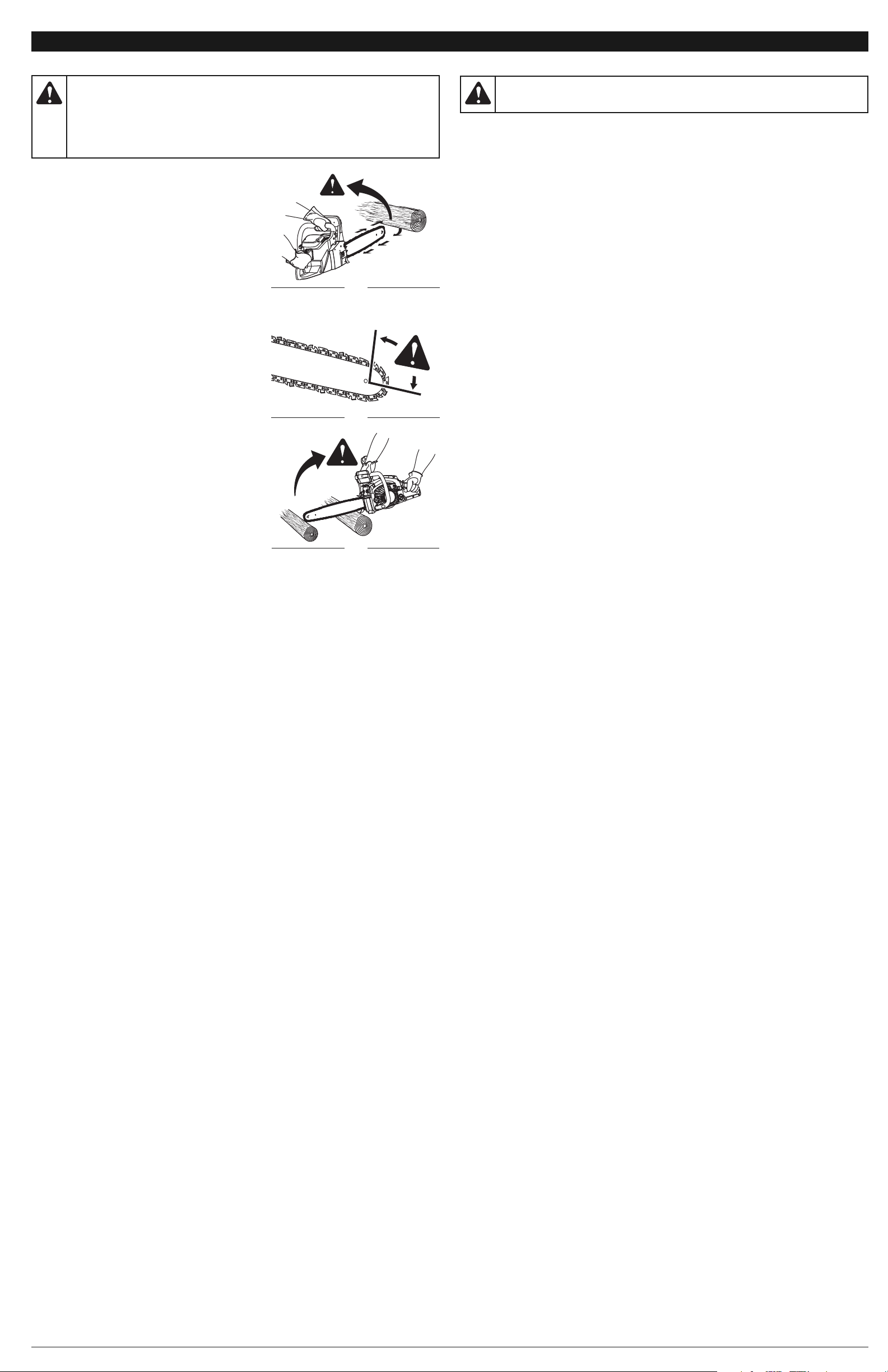
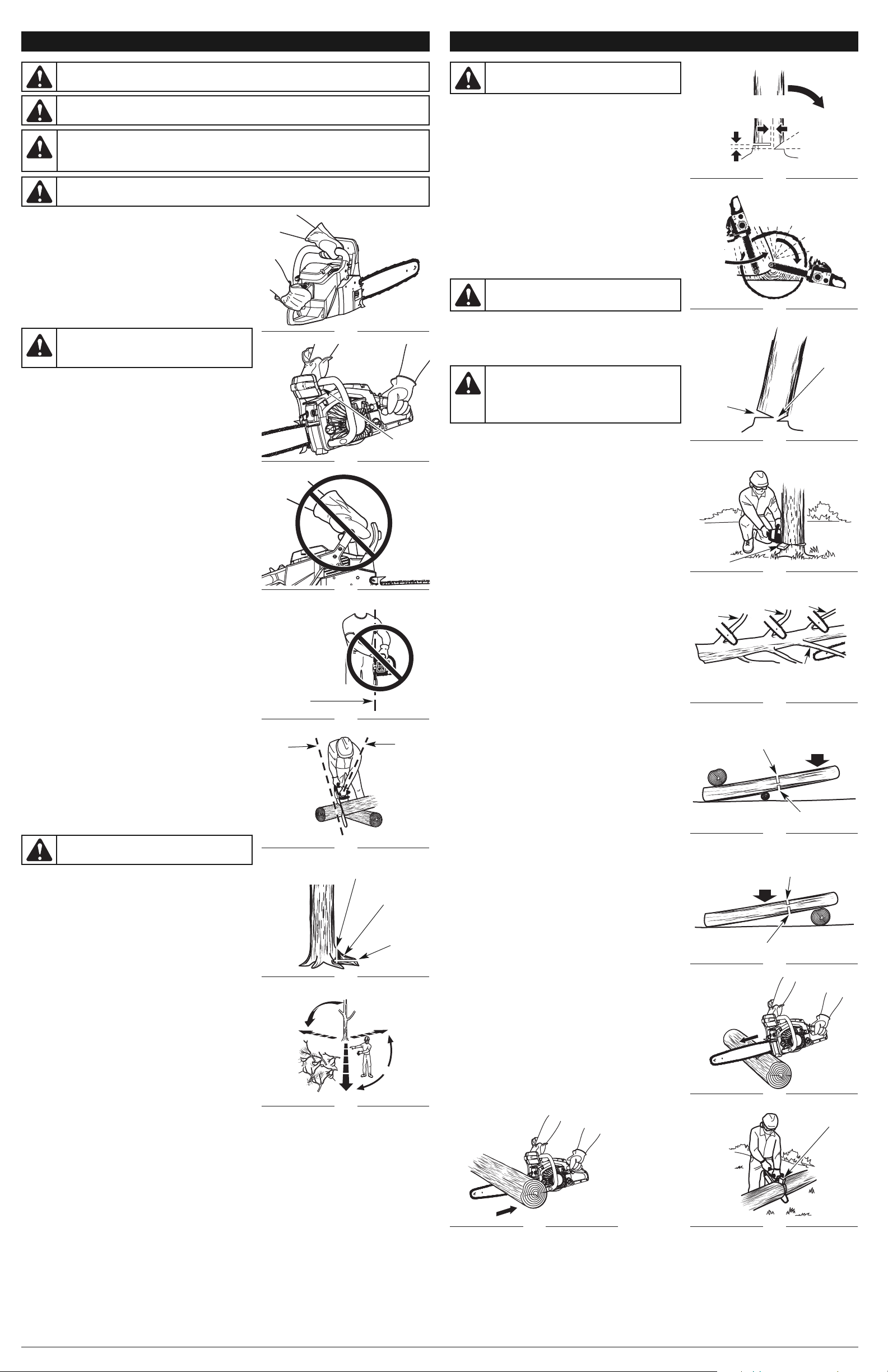
UNDERSTANDING KICKBACK
• Rotational Kickback can happen when the upper tip of
the guide bar contacts an object while the chain is
moving (Fig. 1 & 2). This can cause the chain to dig into
the object and momentarily stop moving. The guide bar
is then kicked up and back toward the operator in a
lightning-fast reverse reaction.
• Pinch Kickback can happen when the wood on either
side of a cut closes in and pinches the moving saw chain
along the top of the guide bar. This can cause the chain
to instantly stop. The chain force is then reversed,
causing the saw to move in the opposite direction,
sending the saw straight back toward the operator.
• Pull-In can happen when the moving chain on the bottom
of the guide bar hits a foreign object inside the wood. This
can cause the chain to suddenly stop. The saw is then
pulled forward and away from the operator, which could
potentially result in the loss of control of the saw.
KICKBACK SAFETY PRECAUTIONS
• DO NOT over reach.
• DO NOT cut above shoulder height.
• DO NOT make cuts with the tip of the guide bar (Fig. 1).
• DO NOT let the tip of the guide bar contact any object,
such as a log, branch, ground or other obstruction.
Remove or avoid any obstructions that might impact the
tip of the guide bar while cutting (Fig. 3).
• DO NOT cut more than one log or branch at a time.
• DO NOT twist the saw when removing the guide bar
from an undercut while bucking.
• DO NOT operate the unit with one hand! Serious injury to
the operator, helpers or bystanders may result from onehanded operation. This unit is intended for two-handed
use. Always grip the unit firmly with both hands when the
engine is running. Keep the left hand on the front handle
and the right hand on the rear handle. Use a firm grip with
thumbs and fingers encircling the handles. A firm grip will
help maintain control of the unit and reduce kickback. Do
not let go! Stand slightly to the left of the unit to avoid
being in the direct line of the saw chain. Follow all the
Proper Grip on Handles instructions in the Operating Instructions section.
• DO NOT install a bow guide on this unit. Bow guides have a larger kickback zone, which increases the
chance of kickback and serious injury. This increased risk is not significantly reduced by using a low
kickback saw chain. Using a bow guide on this unit is extremely dangerous.
• Never start the saw when the guide bar is inside an existing cut. Be extremely careful when re-entering
a cut.
• Keep proper footing and balance at all times.
• Always begin a cut with the engine running at full speed. Fully squeeze the throttle control trigger
and maintain a steady cutting speed. Slower speeds increase the chance of kickback. Keep the
saw housing pressed firmly against the wood.
• Watch for shifting logs, branches, or other objects that might pinch, or fall onto, the chain while cutting.
• If using wedges, only use wedges made of plastic or wood. Do not use metal to hold a cut open.
• Follow the manufacturer’s sharpening and maintenance instructions for the saw chain.
• Only use replacement guide bars and chains specified by the manufacturer or the equivalent.
These are available from authorized service dealers. Use of any unauthorized parts or accessories
could lead to serious injury to the operator or damage to the unit and will void the warranty.
• Use devices, such as low-kickback chains, guide bar nose guards, chain brakes and special guide
bars, which reduce the risks associated with kickback. There are no other replacement
components for achieving kickback protection in accordance with CSA Z62.3.
• Low-kickback saw chain is chain that has met the kickback performance requirements of ANSI
B175.1-1991 and is in accordance with CSA Z62.3. Do not use a replacement chain unless it has
met these requirements for the specific model. As saw chains are sharpened, some of the low
kickback qualities are lost and extra caution should be used.
GENERAL SAFETY PRECAUTIONS
• DO NOT handle the unit with wet hands.
• DO NOT
operate a
chain
saw in a tree or on a ladder unless specifically trained to do so.
• DO NOT use the unit in the presence of flammable liquids or gases.
• DO NOT operate a unit that is damaged, improperly adjusted or not completely and securely
assembled. Be sure that the saw chain stops moving when the throttle control trigger is released.
Do not use the unit if the stop switch does not turn the unit on and off properly or if the lockout
switch does not work. Have defective switches replaced by an authorized service center.
• DO NOT attempt operations beyond the operator’s capacity or experience.
• DO NOT cut near electrical cables or power lines.
• DO NOT force the chain saw, especially near the end of a cut. It will do a better, safer job when
used at the intended rate.
• DO NOT touch the engine or muffler. These parts can become extremely hot during operation and
remain hot for a short time after the unit is turned off.
•
To reduce the risk of fire, keep the engine and muffler free from debris, excessive grease and carbon
build up.
•
Before cutting, always inspect wood for foreign objects that could cause injury to the operator or
damage to the unit. Never cut through nails, metal rods, railroad ties or pallets. If a foreign object is
struck, stop the unit and inspect it for damage.
• Keep all body parts away from the saw chain when the engine is running. Before starting the saw,
make sure the saw chain is not contacting anything.
• Always stop the engine when operation is delayed, before setting down the unit or when walking
from one location to another. Make sure the chain comes to a complete stop. Do not leave the unit
unattended while the engine is running. Always stop the engine when not in use.
•
To avoid accidental starting, never carry the unit with fingers on the throttle control trigger. Only pull the
starter rope when in the starting position. The operator and unit must be in a stable position while
starting the engine. Refer to Starting and Stopping Instructions.
•
Always carry the chain saw by the front handle with the engine off, finger off the throttle control trigger, the
muffler positioned away from the body and the guide bar and saw chain sheathed in the scabbard and
positioned to the rear.
•
Always make sure the stop switch is in the STOP position before starting or stopping the engine.
•
When cutting a limb that is under tension, be alert for spring back, which may cause the operator to
be struck when the tension of the wood fibers is released.
• Use extreme caution when cutting small-sized brush and saplings, as slender material may catch
the saw chain and be whipped toward the operator or pull the operator off balance.
•
This saw is classified by UL as a Class 1C saw
in accordance with CSA Z62.1-03
. It is intended for
infrequent use by homeowners, cottagers and campers, and for general applications such as
clearing, pruning, cutting firewood, etc. It is not intended for prolonged use. If the intended use
involves prolonged periods of operation, this may cause circulatory problems in the user’s hands due
to vibration. It may be appropriate to use a saw having an anti-vibration feature.
Fig. 3
Kickback
GASOLINE SAFETY
• DO NOT smoke while handling fuel or while operating the unit.
• Always keep a fire extinguisher nearby while operating the unit.
• Only store fuel in containers specifically designed and approved for the storage of such materials.
• Avoid creating a source of ignition for spilled fuel. Do not start the engine until fuel vapors dissipate.
• Always stop the engine and allow it to cool before filling the fuel tank. Never remove the cap of the
fuel tank, or add fuel, when the engine is hot. Never operate the unit without the fuel cap securely in
place. Always loosen the fuel tank cap slowly to relieve any pressure in the tank.
• Mix and add fuel in a clean, well-ventilated outdoor area where there are no sparks or flames. Do
not smoke while fueling or mixing fuel. Wipe up any spilled fuel from the unit immediately. Always
wipe unit dry before using.
• Move the unit at least 30 feet (9.1 m) from the fueling source and site before starting the engine. Do
not smoke or allow sparks and open flames near the area while adding fuel or operating the unit.
• Never start or run the unit inside a closed room or building. Breathing exhaust fumes can kill. Only
operate this unit in a well-ventilated outdoor area.
• Always store the unit and fuel in a cool, dry and well-ventilated space where fuel vapors cannot
reach sparks or open flames from water heaters, electric motors or switches, furnaces, etc. Never
store the unit, with fuel in the tank, inside a building where fumes may reach an open flame or spark.
MAINTENANCE AND STORAGE SAFETY
• If the unit is not working as it should, has been dropped, damaged, left outdoors or dropped into
water, do not use the unit. Have the unit serviced by an authorized service center.
• All
service
, other than the
maintenance
procedures described in this manual, should be performed
by an authorized service center.
• Follow all maintenance instructions in this manual.
• Before inspecting, servicing, cleaning, storing, transporting or replacing any parts on the unit:
1. Stop the engine. Make sure the stop switch is in the STOP position and the throttle control trigger
is released.
2.
Make sure all moving parts have stopped.
3. Allow the unit to cool.
4.
Make sure the
chain brake is disengaged.
• Never remove, modify or make inoperative any safety device furnished with the unit.
• For safer, more effective performance, make sure the guide bar and chain are properly cleaned,
lubricated, tightened and sharpened. Check the guide bar and chain at frequent intervals for proper
adjustment.
• Frequently inspect the unit for damage.
Before further use, any damaged part should be carefully
checked to determine that it will operate properly and perform its intended function. Check for
alignment of moving parts, binding of moving parts, breakage of parts, fuel leaks and any other
conditions that may affect its operation. Damaged parts should be properly repaired or replaced by
an authorized service center, unless otherwise indicated in this manual.
• Use only original manufacturer replacement parts and accessories, which are designed specifically to
enhance the performance and maximize the safe operation of the product. Failure to do so may cause
poor performance and possible injury. Use only the chain and guide bar supplied with this product.
• Be sure to secure the unit while transporting.
• Always use the scabbard on the guide bar and saw chain during transportation and storage.
• When not in use, store the unit in a locked-up and dry, or high and dry, place to prevent
unauthorized use or damage. Keep out of the reach of children.
•
Keep the handles dry, clean and free from debris, oil, fuel and grease. Clean the unit after each use.
Never douse or spray the unit with water or any other liquid.
Do not use solvents or strong detergents.
Fig. 2
Kickback Danger Zone
Fig. 1
Rotational Kickback
WARNING:Use caution when handling fuel. Gasoline is highly flammable,
and its vapors can explode if ignited. Take the following precautions:
DANGER:
Kickback may occur when the nose or tip of the guide bar touches an
object, or when the wood closes in and pinches the saw chain in the cut. In some cases, tip
contact may cause a lightening-fast reverse action, kicking the guide bar rapidly back towards
the operator. Pinching the saw chain along the top of the guide bar may push the guide bar
rapidly back towards the operator. Either of these reactions may cause a loss of control over the
saw, which could result in serious injury to the user. Contact with foreign objects within the wood
can also induce a loss of chain saw control.
Page 3
• SAFETY AND INTERNATIONAL SYMBOLS •
This operator's manual describes safety and international symbols and pictographs that may appear
on this product. Read the operator's manual for complete safety, assembly, operating, maintenance
and repair information.
• SAFETY ALERT SYMBOL
Indicates danger, warning or caution. May be used in conjunction with other symbols
or pictographs.
• READ OPERATOR'S MANUAL
WARNING:Read the operator’s manual(s) and follow all warnings and
safety instructions. Failure to do so can result in serious injury to the operator and/or
bystanders.
• WEAR HEAD, EYE AND HEARING PROTECTION
WARNING:Thrown objects and loud noise can cause severe eye injury
and hearing loss. Wear eye protection meeting ANSI Z87.1-1989 standards and ear
protection when operating this unit. Wear head protection when operating this unit;
falling objects can cause severe head injury. Use a full face shield when needed.
• KEEP BYSTANDERS AWAY
WARNING:Keep all bystanders, especially children and pets, at least 50
feet (15 m) from the operating area. If anyone enters the work area, stop the unit!
SYMBOL MEANING
• WEAR SAFETY FOOTWEAR
Wear non-slip safety footwear when using this equipment.
• WEAR SAFETY GLOVES
Wear non-slip, heavy-duty protective gloves when handling the unit.
• KICKBACK WARNING
Contact of the guide bar tip with any object should be avoided. Tip contact may cause
the guide bar to move suddenly upward and backward, which may cause serious injury.
• USE BOTH HANDS
Always use both hands while operating the chain saw. Never use only one hand to
operate the unit.
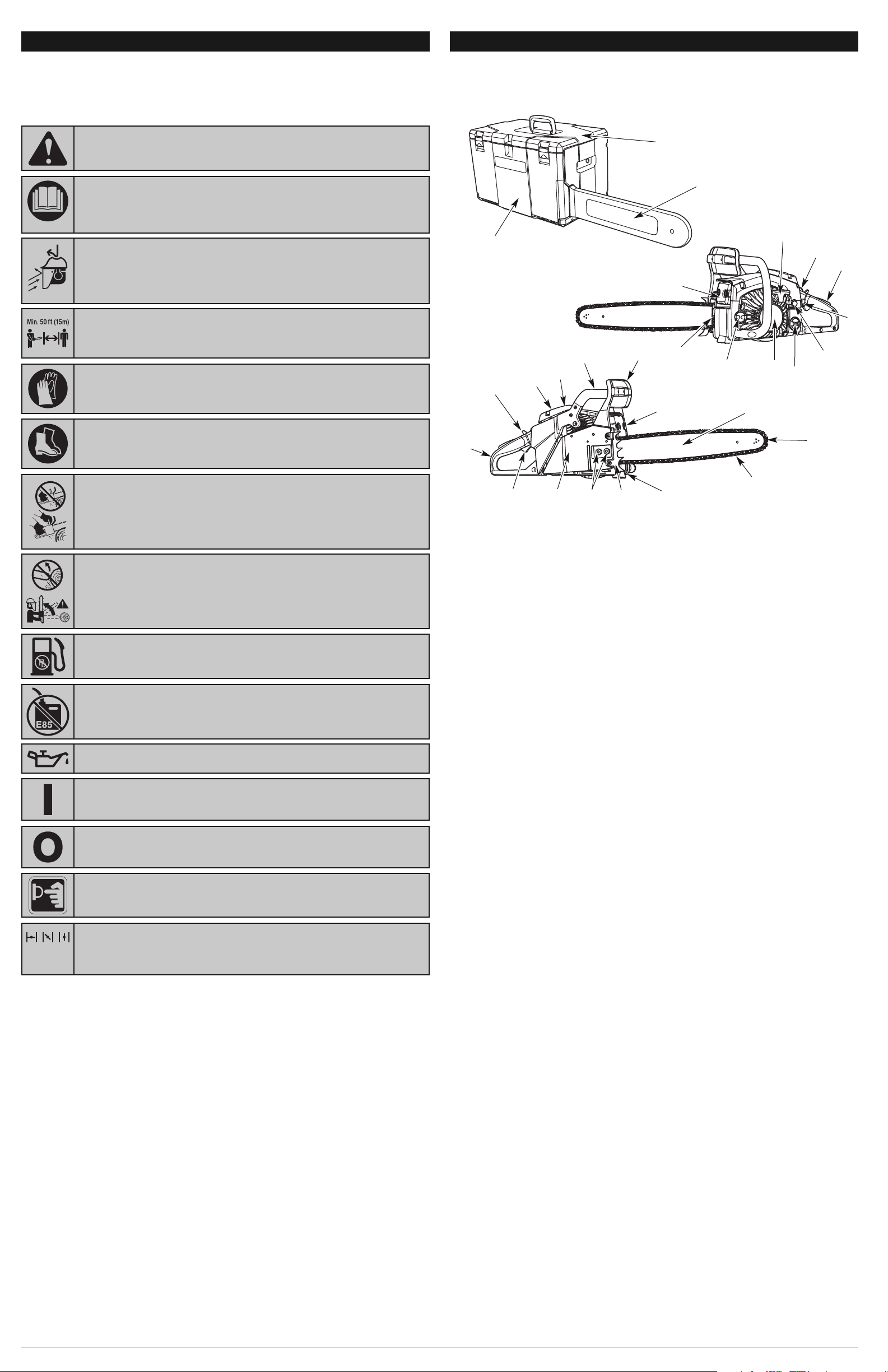
KNOW YOUR UNIT
22
19
10
17
APPLICATIONS
This unit may be used for the purposes listed below:
• Basic limbing, felling and woodcutting
• Removing buttress roots
3
16
14
8
1
13
18
6
7
Guide Bar Tip
• UNLEADED FUEL
Always use clean, fresh unleaded fuel
• OIL
Refer to operator’s manual for the proper type of oil.
• ON/OFF STOP CONTROL
ON / START / RUN
• ON/OFF STOP CONTROL
OFF or STOP
• DO NOT USE E85 FUEL IN THIS UNIT
WARNING:It has been proven that fuel containing greater than 15%
ethanol will likely damage this engine and void the warranty.
SAFETY INFORMATION
26
25
5
27
9
12
21
11
4
15
24
1. GUIDE BAR
2. LOW KICKBACK SAW CHAIN
3. CHAIN-TENSIONING SCREW
4. SPARK ARRESTER SCREEN
5. CHAIN BRAKE LEVER /FRONT HAND GUARD
6. FRONT HANDLE
7. STARTER HANDLE
8. SPARK PLUG
9. AIR FILTER COVER
10. STOP SWITCH
11. SAFETY LATCH
12. BAR LUBE RESERVOIR CAP
13. STARTER COVER
14. FUEL TANK CAP
23
20
2
SAFETY FEATURES
Numbers preceding the descriptions correspond with the numbers above to help you locate the safety feature.
2. LOW KICKBACK SAW CHAIN helps significantly reduce kickback, or the intensity of kickback, due to specially
designed depth gauges and guard links.
4. SPARK ARRESTER SCREEN retains carbon and other flammable particles over 0.023 inches (0.6mm) in size from
engine exhaust flow. Compliance with local, state and federal laws and/or regulations governing the use of a spark
arrester screen is the user’s responsibility. See Safety Information for additional information.
5. CHAIN BRAKE LEVER / FRONT HAND GUARD helps protects the operator’s left hand in the event it slips off the
front handle while the unit is running.
CHAIN BRAKE is designed to reduce the possibility of injury due to kickback by stopping a moving saw chain in
milliseconds. It is activated when pressure is applied to the chain brake lever, as in the event of the operator’s hand
striking the lever during kickback.
10. STOP SWITCH immediately stops the engine when moved to the STOP position. The stop switch must be pushed
to the RUN position to start or restart the engine.
11. SAFETY LATCH prevents accidental acceleration of the engine. The throttle control trigger (20) cannot be squeezed
unless the safety latch is depressed.
21. CHAIN CATCHER reduces the danger of injury in the event the saw chain breaks or derails during operation. The
chain catcher is designed to intercept a whipping chain.
15. REAR HANDLE / BOOT LOOP
16. THROTTLE CONTROL LOCKOUT
17. PRIMER BULB
18. RED CHOKE LEVER
19. BAR-RETAINING NUTS
20. THROTTLE CONTROL TRIGGER
21. CHAIN CATCHER
22. MUFFLER SHIELD
23. GUIDE BAR COVER
24. SPIKED BUMPER / BUCKING SPIKE
25. MULTI-PURPOSE TOOL
26. CARRYING CASE
27. SCABBARD
CHAIN SAW COMPONENTS
• PRIMER BULB
Push primer bulb, fully and slowly, 10 times.
SAVE THESE INSTRUCTIONS
• CHOKE CONTROL
1. • FULL choke position
2. • PARTIAL choke position
3. • RUN position
12
3
Page 4
STARTING AND STOPPING INSTRUCTIONS
BEFORE STARTING THE ENGINE
• Make sure the chain tension is at the desired setting. Refer to Adjusting the Chain Tension in the Maintenance and
Repair section.
• Make sure the bar-retaining nuts are tight to the guide bar cover.
• Make sure the fuel tank is filled with fresh fuel. Refer to Oil and Fuel Information. If the oil and fuel instructions are
not understood, do not attempt to fuel the unit!
• Make sure the bar lube reservoir is filled with bar and chain oil. Refer to Adding Bar and Chain Lubricant in the
Assembly Instructions section.
• Make sure the chain brake is disengaged by pulling the front hand guard / chain brake back toward the front handle
as far as possible. Refer to Testing the Chain Brake in the Assembly Instructions section.
• Make sure the immediate area is clear of any objects or obstructions that could come in contact with the guide bar
and chain.
STARTING THE ENGINE
To help prevent accidental start-ups, this unit has a stop switch,
safety latch, throttle control lockout and a throttle control trigger that
must be used together to start the unit.
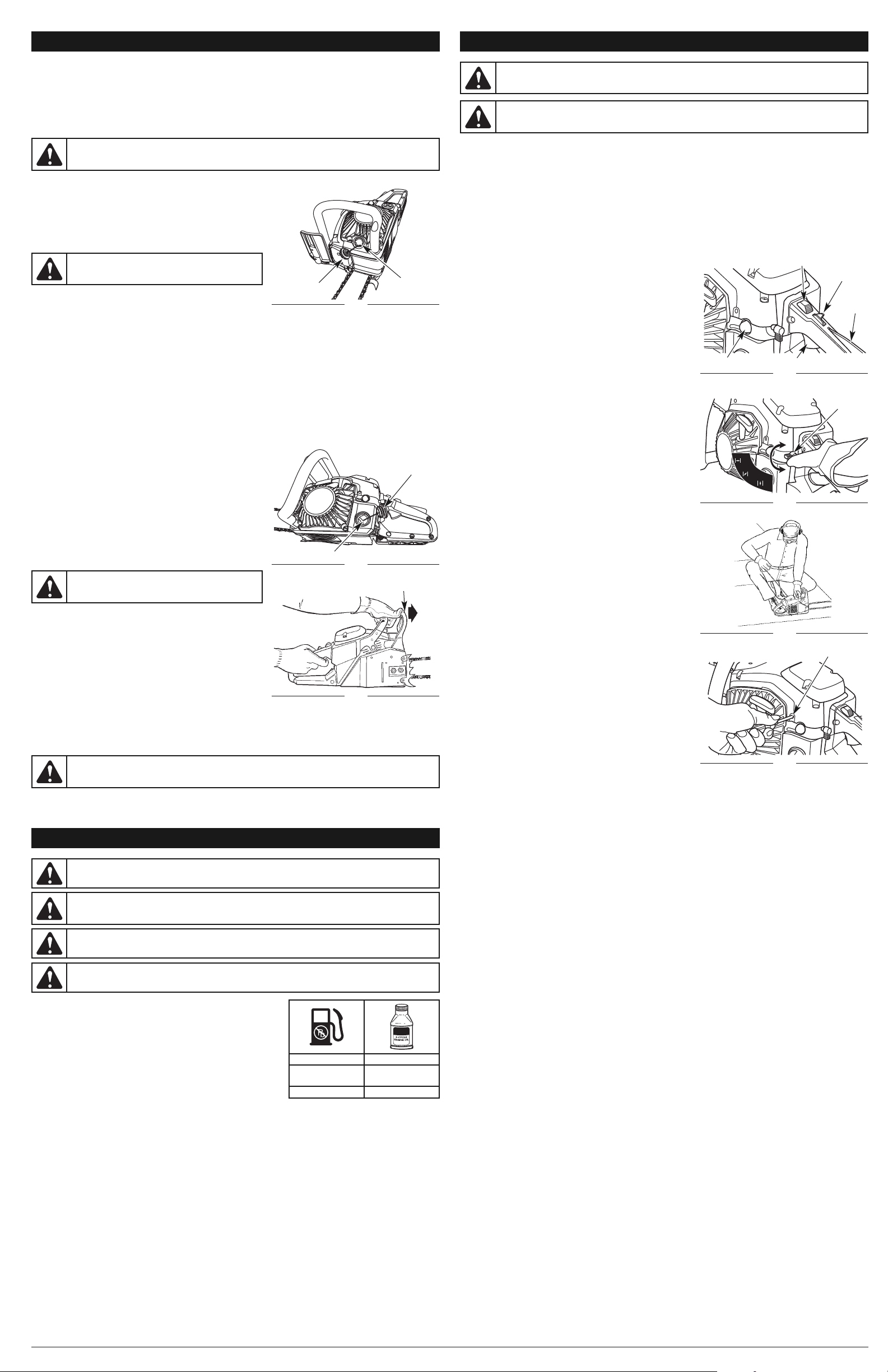
1. Move the stop switch down to the RUN position (Fig. 7).
2. Fully press and release the primer bulb 10 times, slowly (Fig. 7).
Some amount of fuel should be visible in the primer bulb. If fuel
cannot be seen in the bulb, press and release the bulb until fuel is
visible.
3. Move the red choke lever to Position 1 (Fig. 8).
4. Place the unit on a firm, flat surface. Crouch in the starting
position and hold the unit firmly, as shown (Fig. 9).
5. Hold down the safety latch and squeeze the throttle control
trigger. While continuing to squeeze both the safety latch and
throttle control trigger, press down the throttle control lockout with
the thumb. Then release the throttle control trigger. This will lock
the throttle into the wide open position.
6. Pull the starter rope 5 times in a controlled and steady motion.
NOTE: This unit uses the AST starting system, which significantly
reduces the effort required to start the engine. You must pull
the starter rope out far enough to hear the engine attempt to
start. There is no need to pull the rope briskly - there is no
harsh resistance when pulling. Do not pull the rope to its
limit, as this may cause the rope to break. Do not let the
rope snap back. Hold the handle and let the rope rewind
slowly. Be aware that this starting method is vastly different
from (and much easier than) what you may be used to.
7. Keep the throttle control trigger locked. Move the red choke
lever to Position 2 (Fig. 8).
8. Keep the throttle control trigger locked. Pull the starter rope 3-5
times in a controlled and steady motion to start the engine.
9. Keep the throttle control trigger locked. Allow the engine to
warm up for 30-60 seconds.
10. Depress and release the throttle control trigger to idle the engine.
11. Move the red choke lever to Position 3 (Fig. 8). The unit is now
ready for use.
IF... The engine does not start, go back to step 2.
IF... The engine fails to start after a few attempts, move the red
choke lever to Position 3 and squeeze the throttle control
trigger. Pull the starter rope 3-8 times in a controlled and
steady motion. The engine should start. If not, repeat.
IF... The unit idles roughly, use a Phillips or standard screwdriver
to turn the idle adjustment screw (Fig. 10) 1/4 to 1/2 turn
clockwise or until the unit idles smoothly.
IF... The saw chain turns while the unit is idling, use a Phillips or
standard screwdriver to turn the idle adjustment screw (Fig.
10) counterclockwise until the saw chain stops and the unit
continues to idle.
IF... The engine starts and idles smoothly, begin the chain brake
test. Refer to Testing the Chain Brake in the Assembly
Instructions section.
IF WARM...If the engine is already warm, perform steps 7 - 11 to
start the unit.
STOPPING THE ENGINE
1. Release the throttle control trigger and allow the engine to return
to idle speed.
2. Move the stop switch up to the STOP position (Fig. 7).
NOTE: It is normal for the chain to coast to a stop once the stop switch is in the STOP position.
NOTE: For emergency stopping, push the chain brake lever / hand guard forward to engage the chain brake and then
move the stop switch up to the STOP position.
1
2
3
Stop Switch
Fig. 7
OIL AND FUEL INFORMATION
OIL AND FUEL MIXING INSTRUCTIONS
Old fuel and improperly mixed fuel are the two main reasons why the unit
may not run properly. Be sure to use fresh, clean unleaded gasoline and
quality synthetic 2-cycle air-cooled engine oil. Do not use automotive oil or
boat oil; these oils will damage the engine.
Obtaining the Correct Fuel/Oil Mixture
Thoroughly mix the proper amount of 2-cycle engine oil with unleaded
gasoline in a separate fuel container (do not mix them directly in the
engine fuel tank). Use a 40:1 fuel/oil ratio. See the table for specific gas
and oil mixing ratios.
NOTE: One gallon (3.8 liters) of unleaded gasoline mixed with one 3.2 oz.
(95 ml) bottle of 2-cycle oil makes a 40:1 fuel/oil ratio.
When mixing fuel, follow the instructions printed on the oil container. Always read and follow the safety rules relating to
fuel before fueling the unit.
NOTE: Dispose of any old fuel/oil mix in accordance with federal, state and local regulations.
Using Blended Fuels
Today's fuels are often a blend of gasoline and oxygenates such as ethanol, methanol or MTBE (ether). These alcoholblended fuels absorb water. As little as 1% water in the fuel can make fuel and oil separate, which leads to the
formation of acids during storage.
If you choose to use a blended fuel, or its use is unavoidable, follow these precautions:
• Always use fresh fuel (less than 60 days old)
• Mix the fresh unleaded fuel with 2-cycle engine oil, as directed above
• Always agitate (shake) the fuel mix before fueling the unit
• Drain the fuel tank and run the engine dry before storing the unit
Using Fuel Additives
The bottle of 2-cycle oil that came with this unit contains a fuel additive that will help inhibit corrosion and minimize the
formation of gum deposits. Using the 2-cycle oil included with this unit is recommended.
If unavailable, use a good 2-cycle oil designed for air-cooled engines along with a fuel additive, such as STA-BIL
®
Gas
Stabilizer or an equivalent. Add 0.8 oz. (23 ml) of fuel additive per gallon of fuel according to the instructions on the
container. NEVER add fuel additives directly to the unit's fuel tank.
NOTE: Never use engine or carburetor cleaner products in the fuel tank or permanent damage can occur.
WARNING:
Gasoline is extremely flammable. Ignited vapors may explode. Always stop the engine
and allow it to cool before filling the fuel tank. Do not smoke while filling the tank. Keep sparks and open
flames at a distance from the area.
WARNING:
Remove the fuel cap slowly to avoid injury from fuel spray. Never operate the unit without
the fuel cap securely in place.
CAUTION: For proper engine operation and maximum reliability, pay strict attention to the oil and fuel
mixing instructions on the 2-cycle oil container. Using improperly mixed fuel can severely damage the engine.
WARNING: Add fuel in a clean, well-ventilated outdoor area. Wipe up any spilled fuel immediately.
Avoid creating a source of ignition for spilt fuel. Do not start the engine until fuel vapors dissipate.
MIXING RATIO - 40:1
UNLEADED GAS 2 CYCLE OIL
1 GALLON US
(3.8 LITERS)
3.2 FL. OZ.
(95 ml)
1 LITER 25 ml
WARNING: Only operate this unit in a well-ventilated outdoor area. Carbon monoxide exhaust fumes
can be lethal in a confined area.
This unit comes completely assembled. The saw chain may be loose on the guide bar; refer to Adjusting the Chain
Tension in the Maintenance and Repair Instructions section.
UNPACKING
• Carefully remove the product and any accessories from the box.
• Inspect the product carefully to make sure no breakage or damage occurred during shipping.
• Do not discard the packing material until you have carefully inspected and satisfactorily operated the product.
• If any parts are damaged or missing, please call 1-800-828-5500 (U.S.) or 1-800-668-1238 (Canada) for assistance.
ADDING BAR AND CHAIN LUBRICANT
The guide bar and saw chain require lubrication to minimize friction.
Never starve the guide bar and chain of lubricating oil. Running the
unit without enough oil will decrease cutting efficiency, shorten the
life of the saw chain, cause rapid dulling of the saw chain and
excessive wear to the guide bar from overheating. An insufficient
amount of lubricating oil is evidenced by smoke, guide bar
discoloration or pitch build-up.
Fill the bar lube reservoir each time the fuel tank is filled. Only use bar
and chain oil that is formulated to perform over a wide range of
temperatures with no diluting required in the bar lube reservoir. Do
not use motor oil or any other petroleum-based oil.
NOTE: This chain saw comes from the factory with the bar lube reservoir empty. Use the bottle of bar and chain oil that
is included with the unit.
1. Remove the bar lube reservoir cap (Fig. 4).
2. Carefully pour the bar and chain oil into the bar lube reservoir.
3. Replace the bar lube reservoir cap and tighten securely.
4. Wipe off excess oil.
NOTE: Bar lube reservoirs are designed to keep oil slowly flowing onto the chain. This unit will use approximately one
tank of bar and chain oil for every tank of fuel. If the oil flow to the guide bar and chain is too much or too little,
refer to Adjusting the Automatic Oiler in the Maintenance and Repair Instructions section.
NOTE: Do not use dirty, used or otherwise contaminated oils. Damage may occur to the guide bar or chain.
IMPORTANT! Please dispose of oil properly. Consult your local waste authority for information regarding available
disposal options.
FUELING THE ENGINE
This unit is designed to operate on a mixture of unleaded gasoline
and 2-cycle engine oil. Refer to Oil and Fuel Information for complete
mixing instructions and detailed fuel requirements.
1. Turn the unit on its side so that the fuel tank is facing up (Fig. 5).
2. Slowly unscrew and remove the fuel tank cap by turning it anticlockwise.
3. Slowly pour the proper fuel/oil mixture into the fuel tank until the
tank is full.
4. Replace the fuel tank cap and turn it clockwise to secure it tightly.
5. Wipe off any spilled fuel.
TESTING THE CHAIN BRAKE
Always test the chain brake before using the unit and periodically
during operation. Follow these instructions to make sure the chain
brake is working correctly:
1. Place the unit on a clear, firm and flat surface.
2. Pull the chain brake lever back to disengage the chain brake.
3. Start the unit. Refer to Starting and Stopping Instructions. Be sure
to maintain a proper grip. Refer to Proper Grip on Handles in the
Operating Instructions section.
4. While the unit is running, squeeze the throttle control trigger to 1/3
throttle and then engage the chain brake by pushing the chain
break lever forward with the left hand (Fig. 6).
The chain should stop moving abruptly. If it does, immediately release the throttle control trigger, turn off the engine and
return the chain brake to the disengaged position. Refer to Starting and Stopping Instructions.
If the chain does not stop when the chain brake is engaged, release the throttle control trigger, stop the engine and have
the unit serviced by an authorized service center.
ASSEMBLY INSTRUCTIONS
WARNING: Make sure the bar lube reservoir is
always filled. Failure to fill the bar lube reservoir will
cause irreparable damage to the unit.
Fig. 4
Bar Lube
Reservoir
Bar Lube
Reservoir Cap
Fig. 5
Fuel Tank
Cap
Fuel Tank
Fig. 6
Chain Brake
WARNING: Make sure the stop switch is in the STOP position before inspecting, adjusting, fueling or
performing maintenance on any part of the unit. Failure to do so can result in serious personal injury.
Refer to Starting and Stopping Instructions.
WARNING: The chain brake must not move when the engine runs at idle speed. If it does move at
idle speed, refer to the Carburetor Adjustment instructions in the Maintenance and Repair Instructions
section. Avoid contact with the muffler. A hot muffler can cause serious burns.
WARNING: Never operate the unit without the guide bar and saw chain properly installed.
WARNING:
When activating the chain brake, do
so slowly and deliberately. Keep the saw chain from
touching anything; don’t let the saw tip forward.
Primer Bulb
1
2
3
Fig. 8
Red Choke
Lever
Fig. 9
Fig. 10
Idle Adjustment Screw
Throttle
Control
Lockout
Throttle Control Trigger
Safety
Latch
1
2
3
Page 5
Small trees, up to 6-7 inches (15-18 cm) in diameter, are usually felled
in a single cut. Larger trees require a process consisting of two main
cutting operations: a notched undercut followed by a felling back cut.
1. Notched Undercut. This cut determines the direction that the tree
will fall. It should be made on the side of the tree facing the felling
direction. Cut a notch about 1/3 the diameter of the trunk in the
side of the tree. Make the notch cuts so they intersect at a right
angle to the line of fall. This notch should be cleaned out to leave a
straight line. To keep the weight of the wood off the saw, always
make the lower cut of the notch before the upper cut. (Fig. 18)
2. Felling Back Cut. This cut fells the tree. Make the back cut level
and horizontal, and at a minimum of 2 inches (5 cm) above the
horizontal cut of the notch (Fig. 18). If the diameter of the tree is
greater than the length of the guide bar, make two cuts as shown
(Fig. 19). When the felling cut gets close to the hinge, the tree
should begin to fall (Fig. 20). If there is any chance the tree may
not fall in the desired direction or if it may rock back and bind the
saw chain, stop cutting before the felling cut is complete and use
wedges of wood or plastic to open the cut and drop the tree
along its desired line of fall (Fig. 21).
NOTE: On large diameter trees, stop the back cut before it is deep
enough for the tree to either fall or settle back on the stump.
Then insert soft wooden or plastic wedges into the cut so
that they do not touch the chain. Drive wedges in, little by
little, to help jack the tree over.
3. As the tree starts to fall, remove the chain saw from the cut, stop
the engine and put down the unit immediately. Retreat along the
cleared path, but watch the action in case something falls along
the retreat path.
LIMBING
Limbing is the process of removing branches from a fallen tree (Fig. 22).
• Work slowly, while maintaining a proper grip and stance.
• Leave the larger support limbs under the tree to keep the tree off
the ground while cutting.
• Limbs should be cut one at a time. Remove the cut limbs from the
work area often to help keep the work area clean and safe.
• Branches under tension should be cut from the bottom up to avoid
binding the chain saw.
• Keep the tree between you and the chain saw while limbing. Cut
from the side of the tree opposite the branch that is being cut.
BUCKING
Bucking is the process of cutting a fallen tree into desired log lengths.
• Work slowly, while maintaining a proper grip and stance.
• Cut only one log at a time.
• Keep a clear cutting area. Make sure that no objects can contact the
guide bar nose and chain during cutting; this can cause kickback.
Refer to Understanding Kickback in the Safety Information section.
• When bucking on a slope, always stand on the uphill side of the
log. To maintain complete control of the chain saw when cutting
through the log, release the cutting pressure near the end of the
cut without relaxing the grip on the chain saw handles. Do not let
the chain contact the ground. After completing the cut, wait for the
saw chain to stop before moving the chain saw. Always stop the
engine before moving from log to log.
NOTE: If possible, the log should be supported so that the end to
be cut off is not resting on the ground. The best way to hold
a log while bucking is to use a sawhorse. When this is not
possible, the log should be raised and supported by the limb
stumps or by using supporting logs. Be sure the log being
cut is securely supported.
Bucking Logs Under Stress
Make the first bucking cut 1/3 of the way through the log and finish
with a 2/3 cut on the opposite side. The log will tend to bend as it is
being cut. The saw may become pinched or hung in the log if the first
cut is deeper than 1/3 of the diameter of the log. Give special attention
to logs under stress to prevent the guide bar and chain from pinching.
1. When the log is supported on one end (Fig. 23): First, cut from the
bottom (underbuck) 1/3 of the way through the log to avoid
splintering. Second, cut from above (overbuck) to meet the first
cut and avoid pinching.
2. When the log is supported on both ends (Fig. 24): First, overbuck
1/3 of the way through the log to avoid splintering. Second,
underbuck to meet the first cut and avoid pinching.
Bucking Fully Supported Logs
When the log is supported along the entire length, cut from the top
(overbuck), being careful to avoid cutting into the ground (Fig. 25).
Overbucking
Begin on the top side of the log with the bottom of the saw against
the log; exert light pressure downward. During overbucking, the saw
will tend to pull away. Be prepared for this reaction and hold the saw
firmly to maintain control. (Fig. 25)
Underbucking
Begin on the under side of the log with the top of the saw against the
log; exert light pressure upward. During underbucking, the saw will
tend to push back. Be prepared for this reaction and hold the saw
firmly to maintain control. (Fig. 26)
Bucking with a Wedge
If the wood diameter is large enough to insert a soft wooden or
plastic bucking wedge without touching the chain, one should be
used to hold the cut open to prevent pinching. (Fig. 27)
OPERATING INSTRUCTIONS
Fig. 25
Fig. 26
Fig. 23
Fig. 24
Overbucking
Underbucking
Log Supported at One End
Log Supported at Both Ends
First Cut - 1/3 Diameter
Finishing Cut
Load
Load
First Cut - 1/3 Diameter
Finishing Cut
Fig. 27
Wedge
Bucking with
a Wedge
Fig. 22
1
2
3
4
Cut Limbs One at a Time and Leave Support
Limbs Under the Tree Until the Log is Cut
Limbing
OPERATING INSTRUCTIONS
PROPER GRIP ON HANDLES
• Hold the saw firmly with both hands. Always keep the left hand on
the front handle and the right hand on the rear handle so that the
operator’s body is to the left of the chain line (Fig. 11). Use these
hand placements even if the operator is left-handed.
• Maintain a proper grip on the saw whenever the engine is running.
The fingers should encircle the handle and the thumb should wrap
under the handle (Fig. 12). This grip is least likely to be broken by a
kickback or other sudden reaction of the saw. Any grip in which the
thumb and fingers are on the same side of the handle is dangerous
because a slight kick of the saw can cause loss of control (Fig. 13).
PROPER CUTTING STANCE
• Balance body weight securely, with both feet on solid ground.
• Keep the left arm locked in a “straight arm” position to withstand
any kickback force (Fig. 15).
• Keep all body parts to the left of the chain line (Fig. 15).
• Make sure the proper grip is established on the front handle and
rear handle.
• Do not cut above chest height as a saw held higher is difficult to
control against kickback forces.
BASIC OPERATING/CUTTING PROCEDURES
• This unit has a 18” guide bar and is designed to cut logs or trees
with diameters of 14” or less. Cutting larger trees or logs is not
recommended.
• Practice cutting a few small logs using the following technique to get
the “feel” of using the saw before you begin a major sawing operation.
• Take the proper stance in front of the wood or tree to be cut.
• Start the engine and let the chain accelerate to full speed before
starting the cut. Refer to Starting and Stopping Instructions.
• Begin cutting with the saw against the log.
• Keep the unit running the entire time while cutting, making sure to
maintain a steady speed.
• Allow the chain to do the cutting; exert only light downward
pressure. Forcing the cut could result in damage to the guide bar,
chain or engine.
• Release the throttle control trigger as soon as the cut is
completed. Allow the chain to come to a complete stop.
Unnecessary wear may occur to the chain, guide bar and unit if
the saw is run without a cutting load.
• Do not put pressure on the saw at the end of the cut.
WORK AREA PRECAUTIONS
• Cut only wood or materials made from wood. Do not attempt to
cut sheet metal, plastics, masonry or non-wood building materials.
• Keep everyone – helpers, bystanders, children and animals – 50
feet (15 m) away from the cutting area. If anyone enters the work
area, stop the unit! During felling operations, the safe distance
should be at least twice the height of the largest trees in the felling
area. During bucking operations, keep a minimum distance of 15
feet (4.6 m) between workers.
• Only operate the unit when visibility and light are adequate to see
clearly.
REMOVING BUTTRESS ROOTS
A buttress root is a large root extending from the trunk of the tree
above the ground. Remove large buttress roots prior to felling (Fig. 16).
1. Make the horizontal cut into the buttress first, followed by the
vertical cut.
2. Remove the resulting loose section from the work area.
3. Remove any remaining large buttress roots.
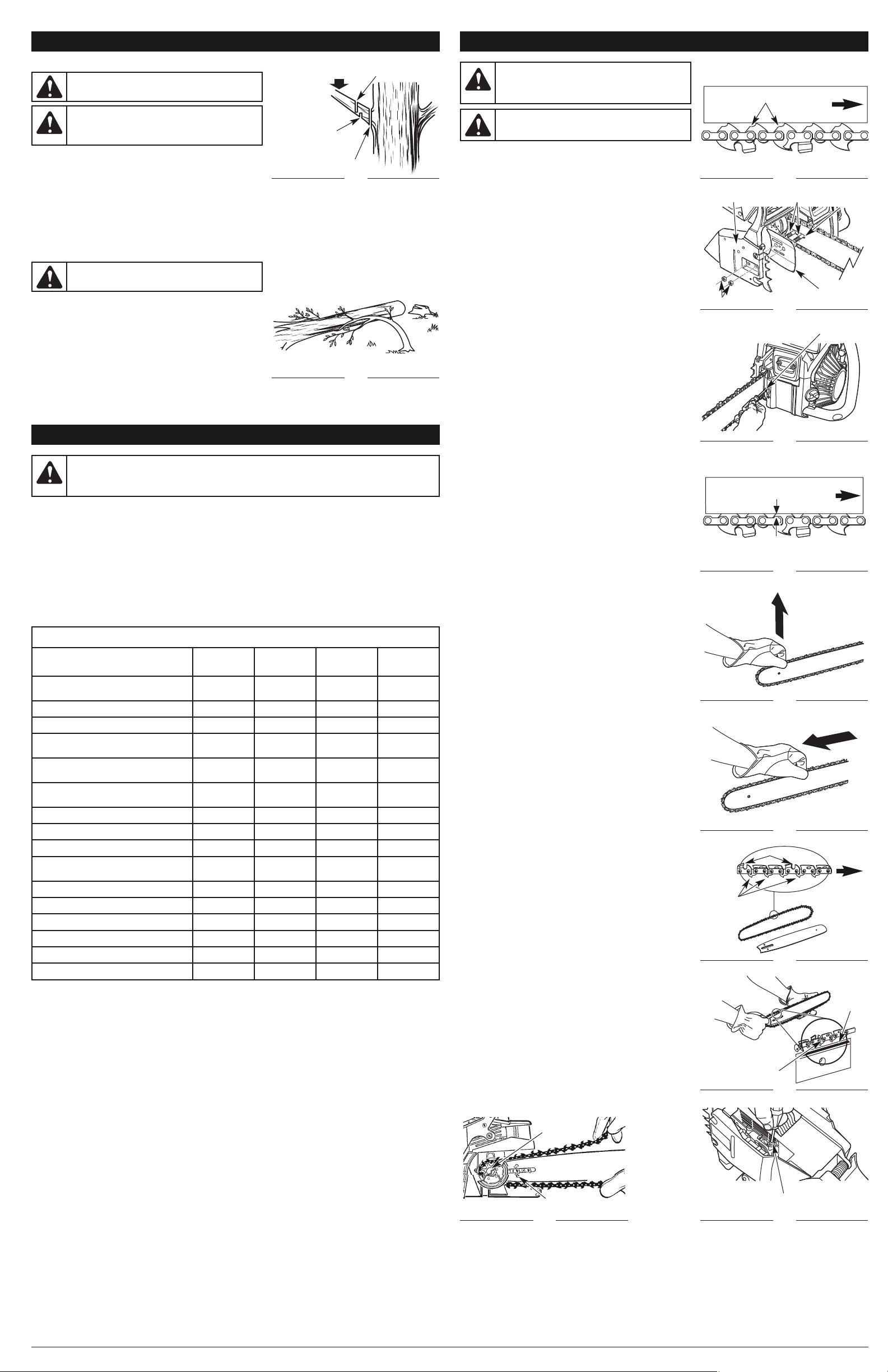
FELLING
Felling is the term for cutting down a tree. When felling a tree, it is
important to heed the following warnings to reduce the risk of serious
injury:
• Do not cut down trees having an extreme lean or large trees with
rotten limbs, loose bark or hollow trunks. Have these trees pushed
or dragged down with heavy equipment, then cut them up.
• Do not cut trees near electrical wires or buildings. Leave this
operation for professionals.
• Check the tree for damaged or dead branches that could fall and
cause serious personal injury.
• Periodically glance at the top of the tree during the back cut to see
if the tree is going to fall in the desired direction.
• If the tree starts to fall in the wrong direction, or the saw gets
caught or hung up during the fall, leave the saw and evacuate the
area immediately!
• When bucking and felling operations are being performed by two or
more persons, at the same time, the felling operation should be
separated from the bucking operation by a distance of at least twice
the height of the tree being felled. Trees should not be felled in a
manner that would endanger any person, strike any utility line or
cause any property damage. If the tree does make contact with any
utility line, the utility company should be notified immediately.
• The operator should keep on the uphill side of terrain, as the tree
is likely to roll or slide after it is felled.
• Pick your escape route (or routes in case the intended route is
blocked). Clear the immediate area around the tree and make sure
there are no obstructions in your planned path of retreat. Clear the
path of safe retreat approximately 135° from the planned line of fall (Fig. 17).
• Consider the force and direction of the wind, the lean and balance of the tree and the location of large limbs. These
things influence the direction in which the tree will fall. Do not try to fell a tree along a line different from its natural
line of fall.
• Remove dirt, stones, loose bark, nails, staples and wire from the tree where felling cuts are to be made.
WARNING: If any parts are damaged or missing, do not operate the unit until the parts are replaced.
Failure to heed this warning could result in serious personal injury.
WARNING: Always wear appropriate eye and ear/hearing protection when operating this unit. Wear
safety goggles, or safety glasses with side shields, that are marked as meeting ANSI Z87.1-1989
standards. Failure to do so could result in serious eye injury caused by thrown objects. If the operation is
dusty, wear a facemask or dust mask. Use a hard hat or other type of safety helmet.
Fig. 11
Proper Hand
Grip Position
Proper
Grip
Fig. 12
Fig. 13
Fig. 14
Improper
Stance
Improper
Grip
WARNING: Do not allow familiarity with this unit to promote carelessness. Remember that a careless
fraction of a second is enough to inflict serious injury.
WARNING:
Do not operate the throttle control
trigger with the left hand while holding the front handle
with the right hand. Never allow any part of your body
to be in the chain line while operating a saw (Fig. 14).
WARNING: Do not fell trees during periods of
precipitation or high wind.
WARNING: Wear non-slip gloves for maximum grip and protection. Refer to the Safety Information
section for appropriate safety equipment.
Fig. 15
Fig. 17
Fig. 18
Fig. 20
Chain Line
Chain
Line
Straight
Left Arm
Planned
Line of Fall
Path of
Safe Retreat
135˚ From
Planned
Line of Fall
Hinge
2” (5 cm) or
1/10 Diameter
Notch - Approx.
1/3 Diameter
of Trunk
Back Cut
2” (5 cm)
Fig. 21
Back Cut
Hinge
Wedge
WARNING: Never cut through to the notch. Always
leave a band of wood between the notch and back cut
(approximately 2 inches (5 cm) or 1/10 the diameter of
the tree). This is called “hinge” or “hingewood.” It
controls the fall of the tree and prevents slipping,
twisting or shootback of the tree off the stump.
Thumb
Below the
Handle
Fig. 16
1stCut - Vertical
2ndCut -
Horizontal
Loose
Section
Removing Buttress
Roots
WARNING: Never walk in front of a tree that has
been notched.
WARNING: Before making the final cut, always
recheck the area for bystanders, animals and
obstacles.
Fig. 19
90°
Page 6
MAINTENANCE AND REPAIR INSTRUCTIONS
ADJUSTING THE CHAIN TENSION
The chain must be tensioned whenever the flats on the drive links
hang out of the bar groove (Fig. 30). Check for proper chain tension
before starting the unit and periodically during operation.
NOTE: A new chain tends to stretch. Check the chain tension
frequently and tighten as required.
1. Stop the engine, wait for all moving parts to stop, allow the unit to
cool, disconnect the spark plug wire and disengage the chain brake.
2. Slightly loosen the bar-retaining nuts (Fig. 31).
3. Hold the guide bar tip up and rotate the chain-tensioning screw
(Fig. 32) clockwise with a standard screwdriver to tension the
chain. The desired tension depends on the temperature of the
chain:
• Cold Chain Tensioning - A cold chain is correctly tensioned
when there is no sag on the underside of the guide bar and the
chain seats snugly against the guide bar with the drive links in
the bar groove.
• Warm Chain Tensioning - During normal operation, the
temperature of the chain will increase. The drive links of a
correctly tensioned warm chain will hang approximately 1/16
inch (1.3 mm) out of the bar groove (Fig. 33).
4. Once adjusted, lift the tip of the guide bar up to check for proper
tension (Fig. 34). If the chain is still too loose, release the tip of the
guide bar and turn the chain-tensioning screw 1/2 turn clockwise.
Repeat this process until the desired tension is achieved.
NOTE: If the chain is too tight, it will not rotate. To loosen the chain,
turn the chain-tensioning screw 1/4 turn counterclockwise.
Ensure that the chain can be turned by hand without binding
(Fig. 35). Also note that the chain will not rotate if the chain
brake is engaged.
5. Hold the tip of the guide bar up and securely tighten the barretaining nuts.
REMOVING/REPLACING THE GUIDE BAR AND CHAIN
Use only a low-kickback saw chain that has met kickback
performance per ANSI B175.1 for this saw. This fast-cutting chain
provides kickback reduction when properly maintained.
NOTE: When replacing the guide bar and chain, use only
manufacturer suggested replacement parts. The use of any
other parts may create a hazard or cause product damage
and will VOID the warranty.
Removing the Old Guide Bar and Chain
1. Make sure the engine is off and the spark plug wire is
disconnected. Disengage the chain brake.
2. Remove the bar-retaining nuts with the supplied multi-purpose
tool. Remove the guide bar cover and guide bar plate by pulling
them straight out (Fig. 31).
3. Remove the guide bar and chain from the mounting surface.
4. Remove the old chain from the guide bar.
Installing the New Guide Bar and Chain
1. Lay out the new saw chain in a loop and straighten any kinks. The
cutters on the top of the guide bar should face toward the guide
bar tip in the direction of chain rotation (Fig. 36). If they face
backward, turn the loop over.
2. Place the chain drive links into the bar groove as shown (Fig. 37).
NOTE: Make sure the chain is correctly installed and the cutters are
facing in the correct direction (Fig. 36).
3. Position the chain so there is a loop at the back of the guide bar.
4. Hold the chain in position on the guide bar and place the loop
around the drive sprocket.
5. Fit the guide bar flush against the mounting surface so that the
two guide bar bolts are in the guide
bar slot (Fig. 31)
.
NOTE: Make sure that the chain-tensioning pin is in the chain-
tensioning pin hole (Fig. 38).
6. Replace the guide bar plate so that the bent edges (top and
bottom) are directed away from the chain.
7. Replace the guide bar cover and bar-retaining nuts. Tighten the
bar-retaining nuts hand tight.
NOTE: Do not over-tighten the bar-retaining nuts. The guide bar
should still be free to move for chain tension adjustment.
8. Adjust the chain tension. Refer to the Adjusting the Chain Tension
instructions above.
ADJUSTING THE AUTOMATIC OILER
The oiler automatically delivers the proper amount of oil to the guide
bar and saw chain. As the engine speed increases, so does the oil
flow. The amount of oil flowing to the guide bar and saw chain may
be changed by turning the adjustment screw with a small standard
screwdriver. Turn the screw clockwise to decrease oil flow or turn the
screw counterclockwise to increase oil flow (Fig. 39).
Flats
Fig. 30
Approx 1/16”
(1.3 mm)
Fig. 33
Fig. 31
Fig. 32
Fig. 36
Fig. 37
Fig. 34
Fig. 35
WARNING: Before inspecting, cleaning or servicing the unit, stop the engine, wait for all moving parts
to stop, allow the unit to cool, disengage the chain brake and disconnect the spark plug wire to ensure
that the unit cannot start. Failure to follow these instructions can result in serious personal injury or
property damage.
WARNING: To avoid possible serious injury, never
touch or adjust the chain while the engine is running.
The saw chain is very sharp; always wear protective
gloves when performing maintenance on the chain.
CAUTION: A chain tensioned while warm, may be
too tight upon cooling. Check the “cold tension”
before next use.
MAINTENANCE AND REPAIR INSTRUCTIONS
Guide Bar Plate
Guide Bar Cover
Bar-retaining Nuts
Guide
Bar Slot
Chain-tensioning Screw
Chain Drive
Links
Chain
Rotation
Cutters
Bar Groove
Chain Drive
Links
Bar Tip
Bar Tip
PRUNING
Pruning is the process of trimming limbs from a live tree (Fig. 28).
• Work slowly, while maintaining a proper grip and stance.
• Do not cut from a ladder; this is extremely dangerous. Leave this
operation for professionals.
• Do not cut above chest height, as a saw held higher is difficult to control during kickback.
• When pruning trees it is important not to make the finishing cut next to the main limb or trunk until the limb is cut
further out to reduce the weight. This prevents stripping the bark from the main member.
1. Underbuck the branch 1/3 through for the first cut.
2. The second cut should overbuck to drop the branch off.
3. Make the finishing cut smoothly and neatly against the main member so the bark will grow back to seal the wound.
CUTTING SPRINGPOLES
A springpole is any log, branch, rooted stump, or sapling that is bent
under tension by other wood so that it springs back if the wood
holding it is cut or removed (Fig. 29). On a fallen tree, a rooted stump
has a high potential of springing back to the upright position during
the bucking cut to separate the log from the stump.
Fig. 28
Fig. 29
Load
First Cut
1/3 Diameter
Finishing Cut
Second Cut
Springpole
WARNING: If the limbs to be pruned are above
chest height, hire a professional to perform the pruning.
WARNING:
Watch for springpoles; these can
strike the operator, causing serious personal injury.
Pruning
WARNING: Use caution when pruning heavy
branches. Falling branches can cause serious injury.
Always wear head protection, plan a safe exit from the
path of falling limbs and stay alert.
OPERATING INSTRUCTIONS
MAINTENANCE SCHEDULE
Perform these required maintenance procedures at the frequency stated in the table. These procedures should also be
a part of any seasonal tune-up.
NOTE: Maintenance, replacement or repair of the emission control devices and system may only be performed by an
authorized service center.
A good preventive maintenance program of regular inspection and care will increase the life and improve performance
the unit. This maintenance checklist is a guide for such a program.
Cleaning, adjusting and part replacement may be required, under certain conditions, at more frequent intervals than
those indicated.
CUSTOMER RESPONSIBILITY
MAINTENANCE CHECKLIST
ACTION
BEFORE EACH
USE
AFTER EACH
USE
AFTER EVERY
10 HOURS OF
OPERATION
AFTER EVERY
20 HOURS OF
OPERATION
Check for loose screws/nuts/bolts and
tighten as needed
3
Clean the air filter (replace when necessary)
3
Clean the fuel filter (replace when necessary)
3
Inspect and clean the spark plug (replace
when necessary)
3
Inspect and clean the spark arrestor screen
and muffler
3
Check the bar lube reservoir level (refill
frequently)
3
Inspect fuel hoses*
3
Inspect the chain brake components*
3
Clean the unit and inspect decals
3
Clean the guide bar groove and oil
passages
3
Clean the cylinder fins
3
Check for damaged or worn parts
3
Check the chain tension (adjust as needed)
3
Check the sharpness of the chain
3
Lubricate the sprocket tip
3
Check the fuel mixture
3
*If maintenance or replacement are required, have the unit serviced by an authorized service dealer.
Fig. 39
Fig. 38
Chain-tensioning
Pin Hole
Drive
Sprocket
Guide Bar Bolts
Automatic Oiler Adjustment Screw
Page 7
MAINTENANCE AND REPAIR INSTRUCTIONS
CHAIN MAINTENANCE
For smooth and fast cutting, the chain needs to be maintained properly.
The following conditions indicate that the chain requires sharpening:
• Wood chips are small and powdery.
• The chain must be forced through the wood during cutting.
• The chain cuts to one side.
During maintenance of the chain, consider the following:
• The depth gauge (or raker clearance) setting determines the height
at which the cutter enters the wood and the size of the wood chip
that is removed (Fig. 40). Too much clearance increases the
potential for kickback. Too little clearance decreases the size of
the wood chip, thus decreasing the chain's cutting ability.
• If the cutter teeth have hit hard objects, such as nails and stones,
or were abraded by mud or sand on the wood, have a service
dealer sharpen the chain.
NOTE: Inspect the drive sprocket for wear or damage when
replacing the chain. If signs of wear or damage are present
in the areas indicated, have the drive sprocket replaced by
an authorized service center.
NOTE: If you do not fully understand the correct procedure for
sharpening the cutters after reading the instructions that
follow, have the saw chain sharpened by an authorized
service center or replace the chain with a recommended
low-kickback chain.
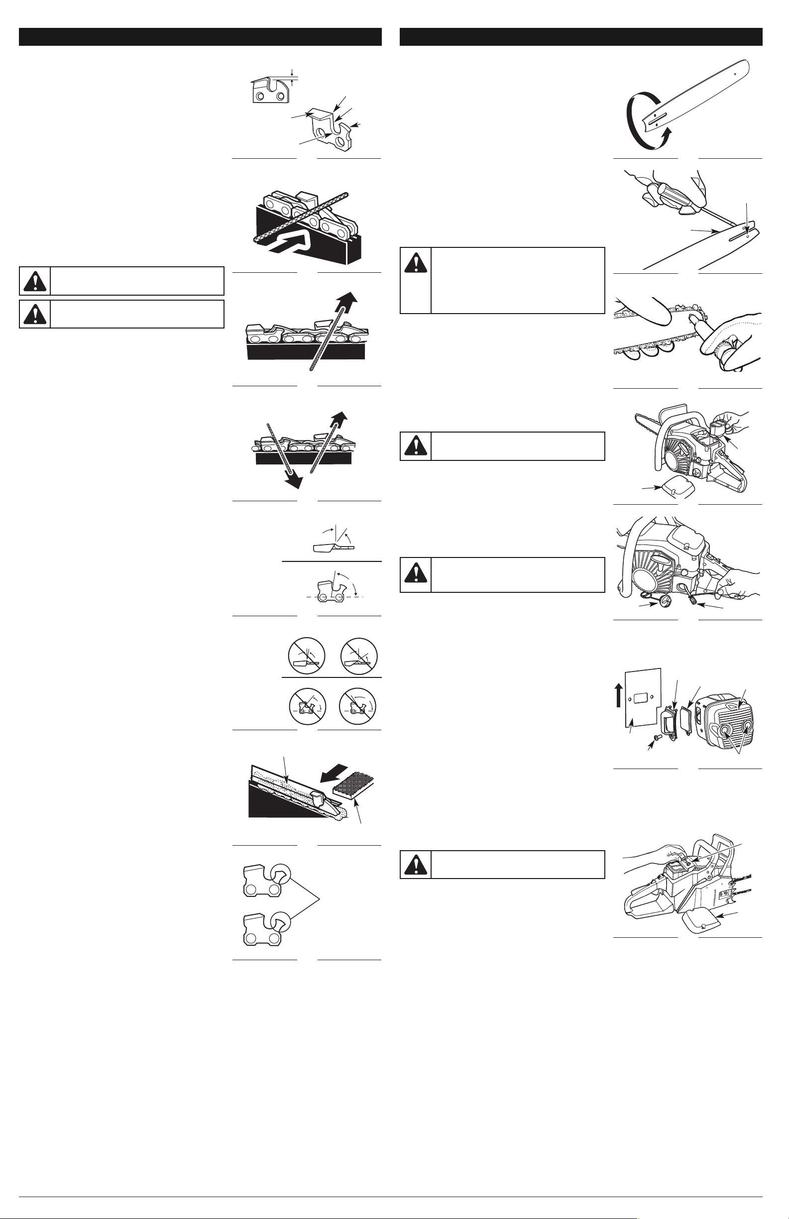
SHARPENING THE CUTTERS
Be careful to file all cutters to the specified angles and to the same
length. Fast cutting can be obtained only when all cutters are uniform.
• Tighten the chain tension enough so that the chain does not
wobble. Do all of the filing at the midpoint of the guide bar. Wear
gloves for protection.
• Use a 3/16” round file and holder.
• Keep the file level with the top plate of the tooth (Fig. 41). Do not
let the file dip or rock (Fig. 42).
• Using light but firm pressure, stroke towards the front corner of the
tooth (Fig. 42). Lift the file away from the cutter before returning
the file to the beginning of the sharpening stroke.
• Put a few firm strokes on every tooth. File all left hand cutters in
one direction (Fig. 43). Then move to the other side and file the
right hand cutters in the opposite direction (Fig. 43). Occasionally
remove filings from the file with a wire brush.
Top Plate Filing Angle
• CORRECT (30°) – File holders are marked with guide marks to align
the file properly and produce the correct top plate angle (Fig. 44).
• INCORRECT (LESS THAN 30°) – For cross cutting (Fig. 45).
• INCORRECT (MORE THAN 30°) – This creates a feathered edge
that dulls quickly.
Side Plate Filing Angle
• CORRECT (80°) – This is produced automatically if the correct
diameter file is used in the file holder (Fig. 44).
• INCORRECT (HOOK) – This causes the chain to “grab” and dull
quickly, increasing the potential for kickback. A hook is caused by
using a file with too small a diameter or a file held too low (Fig. 45).
• INCORRECT (BACKWARD SLOPE) – This causes a need for too
much feed pressure, producing excessive wear to the guide bar
and chain. A backward slope is caused by using a file with too
large a diameter or a file held too high.
MAINTAINING DEPTH GAUGE CLEARANCE
• Maintain the depth gauge at a clearance of 1/32" (0.6 mm). Use a
depth gauge tool for checking the depth gauge clearances. (Fig. 40)
• Every time the chain is filed, check the depth gauge clearance.
• Use a flat file and a depth gauge jointer to lower all gauges
uniformly (Fig. 46). Use a 1/32 inch (0.6 mm) depth gauge jointer.
After lowering each depth gauge, restore the original shape by
rounding the front (Fig. 47). Be careful not to damage adjoining
drive links with the edge of the file.
• Depth gauges must be adjusted with the flat file in the same
direction the adjoining cutter was filed with the round file.
• Use care not to contact the cutter face with the flat file when
adjusting depth gauges.
Top Plate
Fig. 40
Gullet
Fig. 41
Fig. 42
Left Hand
Cutters
Fig. 43
Right Hand
Cutters
Raker Clearance
1/32” (0.6 mm)
Fig. 46
Cutting Corner
Depth
Gauge
Side Plate
Fig. 47
WARNING: A dull or improperly sharpened chain
can cause excessive engine speed during cutting,
which may result in severe engine damage.
WARNING: Improper chain sharpening increases
the potential of kickback. Failure to replace or repair a
damaged chain can cause serious injury.
Flat File
Depth Gauge Jointer
Restore Original
Shape by Rounding
the Front
Filing Height
Filing Angle
Fig. 44
Top Plate
30˚
80˚
Correct
Filing Angles
Side Plate
Fig. 45
Less Than 30˚
More Than 30˚
Incorrect
Filing Angles
Hook
Backward Slope
Top Plate
Side Plate
MAINTAINING THE GUIDE BAR
To minimize guide bar wear, the following maintenance procedures
are recommended:
• Rotate the guide bar frequently at regular intervals (for example,
after every 5 hours of operation), to ensure even wear on the top
and bottom of the guide bar (Fig. 48).
• Clean the guide bar groove and oil passages whenever the saw chain
is removed, when the unit has been used heavily or when the saw
chain appears dirty (Fig. 49). Oil passages can be cleaned with a soft
wire small enough to insert into the oil discharge hole (Fig. 49).
NOTE: If the oil passages are clear, the saw chain will give off a
spray of oil within seconds of starting the unit.
Frequently check the guide bar for damage. Feathering and burring of
the guide bar rails (the ridges on either side of the bar groove) is a
normal process of guide bar wear. Such faults should be smoothed
with a file as soon as they occur.
A guide bar with the following faults should be replaced:
• Wear inside the guide bar rails that permits the chain to lay sideways.
• Bent guide bar.
• Cracked or broken rails.
• Spread rails.
Lubricating the Guide Bar Sprocket Tip
NOTE: It is not necessary to remove the saw chain to lubricate the
guide bar sprocket tip.
1. Clean the guide bar sprocket tip.
2. Insert the tip of the Lube Gun (not included) into the lubrication
hole and inject grease until it appears at the outer edge of the
guide bar sprocket tip (Fig. 50).
NOTE: The Lube Gun is recommended for applying grease to the
guide bar sprocket tip. The Lube Gun is equipped with a
needle nose tip, which is necessary for the efficient
application of grease to the guide bar sprocket tip.
3. Rotate the saw chain by hand. Repeat the lubrication procedure
until the entire guide bar sprocket tip is greased.
CLEANING THE AIR FILTER
1. Remove the air filter cover by loosening the cover-retaining
screws (Fig. 51). The cover will lift off.
2. Remove the air filter.
3. Wash the air filter in clean, warm, soapy water. Rinse the air filter
in clean, cool water. Allow the filter to air dry completely.
NOTE: It is advisable to have a supply of spare air filters.
4. Install the air filter and replace the air filter cover. Make sure the
air filter cover fits properly. Tighten the cover-retaining screws
securely.
REPLACING THE FUEL FILTER
1. Remove the fuel tank cap.
2. Pull the fuel filter out of the fuel tank with a bent wire or long
needle-nosed pliers (Fig. 52). Disconnect and discard the fuel filter.
NOTE: Do not pull the hose completely out of the fuel tank.
3. Install a new fuel filter onto the hose. Push the hose and fuel filter assembly back into the fuel tank so that the fuel
filter is positioned in the right front corner.
4. Fill the fuel tank with fresh fuel/oil mixture. Refer to Oil and Fuel Information. Replace the fuel tank cap.
CLEANING THE SPARK ARRESTOR SCREEN
NOTE: A clogged spark arrestor screen will dramatically reduce
engine performance.
1. Locate the muffler assembly at the front of the unit. Use a T27 Torx
wrench to remove the two muffler-retaining screws (Fig. 53).
2. Remove the muffler assembly and gasket from the unit.
3. Use the multi-purpose tool to remove the deflector-retaining screw.
4. Remove the outer deflector and spark arrestor screen.
5. Use a small wire brush to remove debris from the spark arrestor
screen.
6. Reconnect the spark arrestor screen and outer deflector to the
muffler assembly. Make sure the two tabs on the outer deflector
are inserted into the two slots on the muffler assembly. Tighten
the deflector-retaining screw securely.
7. Insert the two muffler-retaining screws into the muffler assembly. Place the gasket behind the muffler assembly so
that the two muffler-retaining screws pass through the two holes in the gasket. Make sure the narrow end of the
gasket faces the bottom of the muffler assembly (Fig. 53). Insert the muffler assembly and gasket into the cavity at
the front of the unit so that the screws align with the two screw holes in the front cavity. Tighten the mufflerretaining screws securely to a torque of 80-90 in.lbs. If necessary, hold the gasket from the side with a pair of
needle-nose pliers while tightening the screws. If assistance is required for achieving the proper torque, have the
unit serviced by an authorized service dealer.
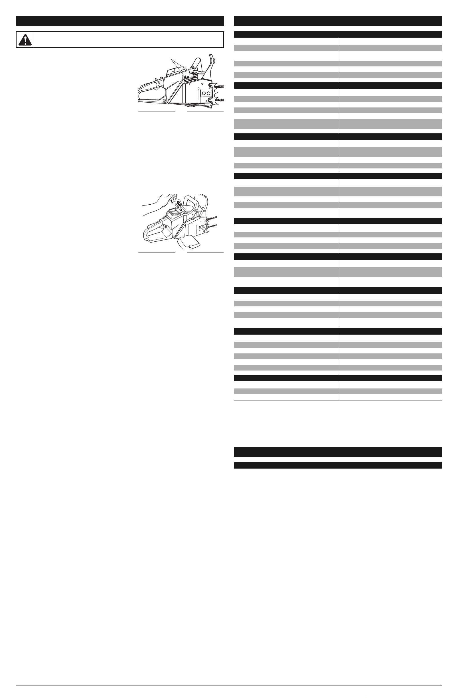
INSPECTING/ADJUSTING/REPLACING THE SPARK PLUG
NOTE: For efficient operation, the spark plug must be kept clean
and properly gapped.
1. Push the stop switch up to the STOP position.
2. Use the multi-purpose tool to remove the two retaining screws
from the top plate (Fig. 54). Remove the top plate.
3. Disconnect the wire connector from the spark plug by pulling and
twisting at the same time (Fig. 54).
4. Remove the spark plug with a spark plug socket wrench. DO NOT USE ANY OTHER TOOL.
5. Check the electrode gaps with a wire feeler gauge. The gap should be set to 0.025 in. (0.635 mm). Adjust the gaps
if necessary.
6. Reinstall the correctly gapped spark plug or, if needed, install a new spark plug (Champion RDJ8J or equivalent).
NOTE: A resistor spark plug must be used for replacement (part number 753-06269 or Champion RDJ8J).
CARBURETOR ADJUSTMENT
The carburetor was pre-set at the factory for optimum performance. If further adjustments are necessary, please have
the unit serviced by an authorized service dealer.
MAINTENANCE AND REPAIR INSTRUCTIONS
Fig. 48
CAUTION: Never operate the unit without the air
filter. Dust and dirt will be drawn into the engine and
damage it. Keep the air filter clean.
CAUTION: Never operate the unit without the fuel
filter. The fuel filter should be replaced after every 20
hours of use. Drain the fuel tank before replacing the
fuel filter.
Fig. 51
Fig. 52
Fig. 53
Fig. 54
WARNING:
Do not sand blast, scrape or clean
spark plug electrodes. Dislodged grit could damage
the cylinder. Replace corroded spark plugs.
CAUTION: The guide bar sprocket tip was pre-
lubricated at the factory. Lubrication of the guide bar
sprocket tip is recommended after every 10 hours of
operation or once per week, whichever comes first.
Always thoroughly clean the guide bar sprocket tip
before lubrication. Failure to lubricate the guide bar
sprocket tip as explained below will result in poor
performance and seizure, voiding the warranty.
Fig. 49
Fig. 50
Air Filter
Cover
Air Filter
Fuel
Tank Cap
Fuel Filter
Spark
Arrestor
Screen
Outer
Deflector
Muffler-retaining Screws
Muffler
Assembly
Top
Plate
Spark
Plug
Guide Bar
Groove
Oil
Passages
Deflector-retaining
Screw
Gasket
Page 8
CAUSE SOLUTION
The carburetor mixture adjustment setting is incorrect Have the carburetor adjusted by an authorized service
center
The fuel mixture is incorrect Drain the fuel tank and add fresh, properly mixed fuel
CAUSE SOLUTION
The spark plug is incorrectly gapped Clean, gap or replace the spark plug
The spark arrestor screen is plugged Clean the spark arrestor screen
The air filter is dirty Clean or replace the air filter
CAUSE SOLUTION
The carburetor mixture adjustment setting is incorrect Have the carburetor adjusted by an authorized service
center
The fuel is old and/or improperly mixed Drain the fuel tank and add fresh, properly mixed fuel
The air filter is plugged Clean or replace the air filter
The spark plug is fouled Clean, gap or replace the spark plug
CAUSE SOLUTION
The carburetor mixture adjustment setting is incorrect Have the carburetor adjusted by an authorized service
center
The air filter is plugged Clean or replace the air filter
The fuel is old and/or improperly mixed Drain the fuel tank and add fresh, properly mixed fuel
THE ENGINE HESITATES
CAUSE SOLUTION
The unit was started incorrectly Follow all Starting and Stopping Instructions
The carburetor mixture adjustment setting is incorrect Have the carburetor adjusted by an authorized service
center
The spark plug is fouled Clean, gap or replace the spark plug
The fuel tank is empty Fill the fuel tank with properly mixed fuel
The primer bulb was not pressed enough Press the primer bulb fully and slowly 10 times
CAUSE SOLUTION
The fuel filter is plugged Replace the fuel filter
The choke lever is in the wrong position Move the choke lever to Position 3
The spark arrestor screen is dirty Clean the spark arrestor screen
The air filter is dirty Clean the air filter
The carburetor mixture adjustment setting is incorrect Have the carburetor adjusted by an authorized service
center
CLEANING INSTRUCTIONS
1. Stop the engine and wait for all moving parts to stop.
2. Allow the unit to cool.
3. Slacken the chain if it was retensioned at operating temperature
during cutting work. The chain contracts as it cools down. If it is
not slackened, it may damage the gearbox and bearings.
4. Wipe the unit down with a damp cloth. Do not douse the unit with
water. Do not use solvents or strong detergents. If preparing the
unit for long-term storage (three months or more), remove the
chain and guide bar, then clean the unit thoroughly with a damp
cloth. A firm-bristled, non-wire, brush can be used to remove
debris from the bar groove and assembly. When finished,
reassemble the unit. Refer to Removing/Replacing the Guide Bar
and Chain.
5. Debris must be removed from the cylinder fins on a regular basis to reduce the risk of damage to the unit and
personal injury from fire. Use compressed air, at 40 PSI or lower, to blow debris from the cylinder fins (Fig. 55).
Always wear safety goggles/glasses when cleaning the cylinder fins with compressed air. Use a small wire brush to
dislodge stubborn debris. Do not use water or solvents on the cylinder fins. If there is a significant amount of debris
that remains after cleaning, have the cylinder fins cleaned by an authorized service dealer.
6. Spray the guide bar and chain with corrosion inhibiting oil.
STORAGE INSTRUCTIONS
NOTE: It is normal for oil to seep from the unit when it is not in use. Please take this into consideration when storing
the unit.
1. Follow the Cleaning Instructions listed above.
2. Attach the scabbard to the guide bar and chain.
3. Store the unit in a dry, high and/or locked location, out of the reach of children and other unauthorized persons.
Always store the unit and fuel in a cool, well-ventilated space where fuel vapors cannot reach sparks or open
flames from water heaters, electric motors or switches, furnaces, etc. Never store the unit, with fuel in the tank,
inside a building where fumes may reach an open flame or spark.
Long-term Storage Instructions
In addition to the standard storage instructions described above,
perform the following steps when storing the unit for 30 days or more:
1. Drain the fuel tank by running the unit dry. Alternatively, tip the
engine housing/fuel tank over to pour the fuel mixture into a
suitable container and then run the engine until it stops in order to
remove fuel from the carburetor.
2. Allow the engine to cool.
3. Remove the spark plug. Refer to Inspecting/Adjusting/Replacing
the Spark Plug.
4. Pour 1 teaspoon or clean 2-cycle oil into the combustion chamber
(Fig. 56). Pull the starter rope slowly several times to coat the
internal components.
5. Replace the spark plug.
Removing a Unit From Long-term Storage
1. Remove the spark plug.
2. Pull the starter rope briskly to clear excess oil from the combustion chamber.
3. Clean and gap, or replace, the spark plug.
4. Prepare the unit for operation.
WARNING: Do not let brake fluids, gasoline, petroleum-based products, penetrating oils, etc., come
in contact with plastic parts. These chemicals may damage, weaken and destroy plastic, which may
result in serious personal injury.
SPECIFICATIONS
CHAIN SAW*
* All specifications are based on the latest product information available at the time of printing. We reserve the right
to make changes at any time without notice.
Engine Type . . . . . . . . . . . . . . . . . . . . . . . . . . . . . . . . . . . . . . . . . . . . . . . . . . . . . . . . . . . . . . . . . . . . . Air-Cooled, 2-Cycle
Displacement . . . . . . . . . . . . . . . . . . . . . . . . . . . . . . . . . . . . . . . . . . . . . . . . . . . . . . . . . . . . . . . . . . . . . . 55 cc (3.36 cu in)
Idle Speed . . . . . . . . . . . . . . . . . . . . . . . . . . . . . . . . . . . . . . . . . . . . . . . . . . . . . . . . . . . . . . . . . . . . . . . . . . . . . . 2,800 rpm
Operating Speed . . . . . . . . . . . . . . . . . . . . . . . . . . . . . . . . . . . . . . . . . . . . . . . . . . . . . . . . . . . . . . . . . . . . . . . . . 8,500 rpm
Ignition Type . . . . . . . . . . . . . . . . . . . . . . . . . . . . . . . . . . . . . . . . . . . . . . . . . . . . . . . . . . . . . . . . . . . . . . . . . . . . . Electronic
Ignition Switch . . . . . . . . . . . . . . . . . . . . . . . . . . . . . . . . . . . . . . . . . . . . . . . . . . . . . . . . . . . . . . . . . . . . . . . . . Slide Switch
Starter. . . . . . . . . . . . . . . . . . . . . . . . . . . . . . . . . . . . . . . . . . . . . . . . . . . . . . . . . . . . . . . . . . . . . AST Starting Auto Rewind
Throttle Control . . . . . . . . . . . . . . . . . . . . . . . . . . . . . . . . . . . . . . . . . . . . . . . . . . . . . . . . . . . . . . . . . . . . Finger-Tip Trigger
Throttle . . . . . . . . . . . . . . . . . . . . . . . . . . . . . . . . . . . . . . . . . . . . . . . . . . . . . . . . . . . . . . . . . . . . . . . Manual Spring Return
Spark Plug Gap . . . . . . . . . . . . . . . . . . . . . . . . . . . . . . . . . . . . . . . . . . . . . . . . . . . . . . . . . . . . . . . . . . 0.025 in (0.635 mm)
Carburetor . . . . . . . . . . . . . . . . . . . . . . . . . . . . . . . . . . . . . . . . . . . . . . . . . . . . . . . . . . . . . . . . . . . Diaphragm, All-Position
Muffler . . . . . . . . . . . . . . . . . . . . . . . . . . . . . . . . . . . . . . . . . . . . . . . . . . . . . . . . . . . . . . . . . . . . . . . . . . Baffled with Guard
Drive Sprocket . . . . . . . . . . . . . . . . . . . . . . . . . . . . . . . . . . . . . . . . . . . . . . . . . . . . . . . . . . . . . . . . . . . . . . . . . . . . . 6-Tooth
Lubrication . . . . . . . . . . . . . . . . . . . . . . . . . . . . . . . . . . . . . . . . . . . . . . . . . . . . . . . . . . . . . . . . . . . . . . . . Bar and Chain Oil
Bar Lube Reservoir Capacity. . . . . . . . . . . . . . . . . . . . . . . . . . . . . . . . . . . . . . . . . . . . . . . . . . . . . . . . . . . 6.8 fl oz (201 ml)
Fuel/Oil Ratio. . . . . . . . . . . . . . . . . . . . . . . . . . . . . . . . . . . . . . . . . . . . . . . . . . . . . . . . . . . . . . . . . . . . . . . . . . . . . . . . . 40:1
Fuel Tank Capacity . . . . . . . . . . . . . . . . . . . . . . . . . . . . . . . . . . . . . . . . . . . . . . . . . . . . . . . . . . . . . . . . 16.8 fl oz (496.8 ml)
Cutting Diameter . . . . . . . . . . . . . . . . . . . . . . . . . . . . . . . . . . . . . . . . . . . . . . . . . . . . . . . . . . . . . . . . . . . . . 36 in (91.4 cm)
Bar Length . . . . . . . . . . . . . . . . . . . . . . . . . . . . . . . . . . . . . . . . . . . . . . . . . . . . . . . . . . . . . . . . . . . . . . . . . . 18 in (45.7 cm)
Chain Pitch. . . . . . . . . . . . . . . . . . . . . . . . . . . . . . . . . . . . . . . . . . . . . . . . . . . . . . . . . . . . . . . . . . . . . . . . . . 3/8 in (9.5 mm)
Chain Gauge. . . . . . . . . . . . . . . . . . . . . . . . . . . . . . . . . . . . . . . . . . . . . . . . . . . . . . . . . . . . . . . . . . . . . . . 0.05 in (1.27 mm)
Approximate Unit Weight (no fuel) . . . . . . . . . . . . . . . . . . . . . . . . . . . . . . . . . . . . . . . . . . . . . . . . . . . . . . . 17.5 lbs (7.9 kg)
CLEANING AND STORAGE
CAUSE SOLUTION
The chain is dull Sharpen the chain
The chain is on backwards Reverse the direction of the chain
TROUBLESHOOTING
NOTE: For repairs beyond the minor adjustments listed above, locate your nearest authorized service center by
calling the Customer Support Department at 1-800-828-5500 (U.S.) or 1-800-668-1238 (Canada).
CAUSE SOLUTION
The chain tension is too tight Adjust the chain tension
The bar lube reservoir is empty Refill the bar lube reservoir
The guide bar groove and/or oil passages are dirty Clean the guide bar groove and oil passages
The oil flow from the automatic oiler to low Increase the oil flow from the automatic oiler
CAUSE SOLUTION
The chain tension is too tight Adjust the chain tension
The guide bar and chain are assembled incorrectly Refer to Removing/Replacing the Guide Bar and Chain
The guide bar and chain are damaged Inspect the guide bar and chain for damage
The drive assembly is damaged Refer to Service Information
The chain brake is engaged Disengage the chain brake
THE CHAIN DOES NOT ROTATE WHILE THE ENGINE IS RUNNING
THE CHAIN ROTATES, BUT DOES NOT CUT
REPLACEMENT PARTS
Description
18-inch Chain
18-inch Guide Bar
Bar Lube Reservoir Cap
Bar-retaining Nuts
8 oz Bar and Chain Oil
Part #
753-06265 . . . . . . . . . . . . . . . . . . . . . . . . . . . . . . . . . . . .
753-06264 . . . . . . . . . . . . . . . . . . . . . . . . . . . . . . . . . . . .
753-06270 . . . . . . . . . . . . . . . . . . . . . . . . . . . . . . . . . . . .
753-06271 . . . . . . . . . . . . . . . . . . . . . . . . . . . . . . . . . . . .
753-06272 . . . . . . . . . . . . . . . . . . . . . . . . . . . . . . . . . . . .
THE GUIDE BAR AND CHAIN ARE RUNNING HOT AND SMOKING OR STUCK
THE UNIT STARTS, BUT THE ENGINE HAS LOW POWER
THE UNIT WILL NOT START OR STARTS BUT DOES NOT CONTINUE TO RUN
THERE IS NO POWER WHEN THE UNIT IS UNDER LOAD
THE ENGINE RUNS ERRATICALLY
THE ENGINE SMOKES EXCESSIVELY
Fig. 56
Fig. 55
Cylinder Fins
Page 9

LIRE TOUTES LES INSTRUCTIONS AVANT UTILISATION
PRECAUTIONS DE SECURITE ELEMENTAIRES
• NE vous fiez PAS exclusivement aux protections de sécurité incorporées dans l’appareil.
• NE PAS laisser l'unité à être utilisé comme un jouet.
• Veuillez lire ce manuel de l’utilisateur attentivement et dans sa totalité avant d’essayer de monter,
d’utiliser ou d’entretenir l’appareil.
• Conformez-vous à toutes les consignes de sécurité. Le non respect de ces consignes peut
entraîner des dégâts matériels ou des blessures graves pour vous-même et/ou pour les autres.
• Familiarisez-vous avec les commandes et la marche à suivre pour une utilisation correcte de cet
appareil. Apprenez à rapidement couper le moteur de l’appareil et à mettre les commandes en
position neutre.
• Restez attentif. N’utilisez pas cet appareil lorsque vous êtes fatigué, malade, ou sous l’influence de
l’alcool, de drogues, ou de médicaments.
• Ne laissez jamais les enfants utiliser cet appareil. Ne laissez jamais des adultes utiliser cet appareil sans
qu’ils aient reçu une formation appropriée.
• Assurez-vous que toutes les protections et tous les dispositifs de sécurité ont été correctement
installés avant d’utiliser l’appareil.
• Conservez ces instructions. Consultez-les régulièrement et utilisez-les pour donner des consignes
aux autres utilisateurs. Si vous prêtez cet appareil à quelqu’un, prêtez-lui également ces instructions.
• Faites reculer les personnes se trouvant à proximité, en particulier les enfants et les animaux, d’au
moins 50 pieds (15 m). Si quelqu’un s’approche de la zone de travail, arrêtez l’appareil !
• Veillez à ce que la zone de travail soit dégagée. Les zones encombrées favorisent les accidents. Ne
commencez pas à couper avant d’avoir nettoyé la zone de tous débris, d’avoir une position
parfaitement stable, et de vous être assuré qu’il y a suffisamment d’espace pour reculer en cas de
chute de branches.
• Portez toujours des protections oculaires et auditives lorsque vous utilisez cet appareil. Portez des
lunettes de sécurité ou une visière dotée de protections latérales conformes aux normes ANSI
Z87.1-1989. Le non-port de ces protections peut entraîner de graves lésions oculaires suite à la
projection ou la chute d’objets. Si la tâche est poussiéreuse, portez un masque anti-poussière.
Portez un casque de sécurité.
• Habillez-vous de manière adéquate, portez des vêtements épais et près du corps (pantalon et
chemise à manches longues), des gants antidérapants et des chaussures de sécurité à bout
renforcé en acier. Ne portez pas de vêtements amples, de bijoux, de pantalons courts, de sandales
et ne soyez pas pieds nus. Attachez-vous les cheveux au dessus du niveau des épaules pour éviter
qu’ils ne se prennent dans les parties en mouvement de l’appareil.
• Utilisez l’appareil uniquement à la lumière du jour ou sous un éclairage artificiel satisfaisant.
• N’utilisez cet appareil que pour des fonctions pour lesquelles il a été conçu : couper du bois.
Utilisez l’appareil uniquement tel qu’indiqué dans ce manuel. Utilisez uniquement les accessoires
recommandés par le fabricant avec cet appareil.
• CONSIGNES DE SÉCURITÉ IMPORTANTES •
Manuel de l’utilisateur
Tronçonneuse 55cc 2 temps
TB5518
TABLE DES MATIÈRES
Informations sur l’entretien et le service après-vente . . . . . . . . . . . . . . . . . . . . . . . . . . . . . . . . . . .F1
Informations sur la sécurité . . . . . . . . . . . . . . . . . . . . . . . . . . . . . . . . . . . . . . . . . . . . . . . . . . . . . .F1
Familiarisez-vous avec votre appareil . . . . . . . . . . . . . . . . . . . . . . . . . . . . . . . . . . . . . . . . . . . . . . .F3
Instructions d’assemblage . . . . . . . . . . . . . . . . . . . . . . . . . . . . . . . . . . . . . . . . . . . . . . . . . . . . . . .F4
Informations sur l’huile et le carburant . . . . . . . . . . . . . . . . . . . . . . . . . . . . . . . . . . . . . . . . . . . . .F4
Instructions de démarrage et d’arrêt . . . . . . . . . . . . . . . . . . . . . . . . . . . . . . . . . . . . . . . . . . . . . . .F4
Instructions d’utilisation . . . . . . . . . . . . . . . . . . . . . . . . . . . . . . . . . . . . . . . . . . . . . . . . . . . . . . . . .F5
Entretien et réparations . . . . . . . . . . . . . . . . . . . . . . . . . . . . . . . . . . . . . . . . . . . . . . . . . . . . . . . . . .F6
Nettoyage et rangement . . . . . . . . . . . . . . . . . . . . . . . . . . . . . . . . . . . . . . . . . . . . . . . . . . . . . . . . .F8
Résolution des problèmes . . . . . . . . . . . . . . . . . . . . . . . . . . . . . . . . . . . . . . . . . . . . . . . . . . . . . . .F8
Spécifications . . . . . . . . . . . . . . . . . . . . . . . . . . . . . . . . . . . . . . . . . . . . . . . . . . . . . . . . . . . . . . . . .F8
Garantie . . . . . . . . . . . . . . . . . . . . . . . . . . . . . . . . . . . . . . . . . . . . . . . . . . . . . . . . . . . . . . . . . . . . .E8
NE RAMENEZ PAS CET APPAREIL CHEZ LE DÉTAILLANT. UNE PREUVE D’ACHAT SERA EXIGÉE
POUR TOUTE PRISE EN CHARGE DANS LE CADRE DE LA GARANTIE.
CE PRODUIT EST COUVERT PAR UN OU PLUSIEURS BREVETS AUX ÉTATS UNIS. AUTRES BREVETS
EN INSTANCE.
Si vous éprouvez des difficultés à assembler ce produit ou si vous avez des questions sur les
commandes, l'utilisation ou l'entretien de cet appareil, veuillez contacter le service à la clientèle. Des
informations supplémentaires sont disponibles sur notre site web.
Pour un entretien ou une réparation, veuillez appeler le service à la clientèle pour obtenir une liste complète
des concessionnaires agrées près de chez vous. L’entretien de cet appareil doit être confié exclusivement à
un concessionnaire agrée pendant et après la période de garantie. Lors de l’entretien, utilisez uniquement
des pièces de rechange identiques.
Avant de contacter le service après-vente, repérez la plaque mentionnant le modèle et le numéro de
série de votre appareil. Reportez-vous à l’exemple ci-dessous et notez-y les informations pour
pouvoir vous y référer ultérieurement.
NE RAMENEZ PAS CET
APPAREIL AU MAGASIN
Pour obtenir de l’aide, veuillez appeler le service à la clientèle
ou visitez notre site web :
ou
INFORMATIONS SUR LA SECURITÉ
CONSERVEZ CES INSTRUCTIONS
L’ensemble des informations, illustrations et caractéristiques sont basées sur les toutes dernières
informations disponibles sur le produit à l’impression de ce guide. Nous nous réservons le droit
d’effectuer des modifications à tout moment sans notification préalable.
Copyright© 2009 MTD SOUTHWEST INC, Tous droits réservés.
INFORMATIONS SUR L’ENTRETIEN ET LE SERVICE APRÈS-VENTE
AVERTISSEMENT :Lors de l’utilisation de cet appareil, respectez
toujours les précautions de sécurité élémentaires afin de réduire les risques de dégâts
matériels et de blessures graves :
aux États Unis
1-800-828-5500
www.troybilt.com
au Canada
1-800-668-1238
www.troybilt.ca
REMARQUE CONCERNANT LE PARE-ÉTINCELLES
REMARQUE : À l'intention des utilisateurs utilisant l’appareil dans les terres forestières des
États-Unis et dans les états de Californie, du Maine, de l'Oregon et de Washington. Toutes les
terres forestières des États-Unis et de l'état de Californie (Codes sur les ressources publiques 4442 et
4443), de l'Oregon et de Washington exigent de par la loi que certains moteurs à combustion interne
utilisés dans des zones couvertes de taillis et/ou d'herbes soient équipés d'un pare-étincelles en
parfait état de fonctionnement, ou qu'ils soient conçus, équipés et entretenus pour la prévention des
incendies. Renseignez-vous auprès des autorités locales ou régionales concernant la réglementation
en vigueur. Vous pourriez être passible d'une amende ou être tenu responsable si vous ne respectez
pas cette réglementation. Cet appareil est équipé d'un pare-étincelles en usine. Si l'écran pare-
étincelles, réf. 753-06268, doit être remplacé, contactez votre RÉPARATEUR LOCAL AGRÉE.
AVERTISSEMENT RELATIF A LA PROPOSITION 65 DE L’ÉTAT DE CALIFORNIE
AVERTISSEMENT
LES GAZ D'ÉCHAPPEMENT DU MOTEUR DE CET APPAREIL CONTIENNENT DES PRODUITS
CHIMIQUES CONSIDÉRÉS PAR L'ÉTAT DE CALIFORNIE COMME POUVANT PROVOQUER DES
CANCERS, DES MALFORMATIONS CONGÉNITALES OU D'AUTRES EFFETS NOCIFS SUR LA
REPRODUCTION.
Copiez ici le nº de série :
Copiez ici le modèle ainsi que le nº de l’article :
DANGER :Signale un risque EXTREME.
Le non respect d’une consigne de sécurité relative à un signal de DANGER entraînera des
blessures graves ou mortelles pour vous-même ou pour les autres.
AVERTISSEMENT :
Signale un risque GRAVE.
Le non respect d’un AVERTISSEMENT de sécurité PEUT entraîner des blessures graves
pour vous-même ou pour les autres.
ATTENTION :
Signale un risque MOYEN.
Le non respect d’une consigne de signal d’ATTENTION PEUT entraîner des dégâts
matériels ou des blessures graves pour vous-même ou pour les autres.
IMPORTANT ! Signale une information technique spécifique.
REMARQUE : Signale une information générale importante supplémentaire.
SYMBOLE SIGNIFICATION
• SYMBOLE D’ALERTE DE SECURITÉ •
L’objectif de ces symboles d’alerte de sécurité est d’attirer votre attention sur les dangers possibles.
Vous devez être attentifs aux symboles de sécurité, et à leurs explications. Les avertissements de
sécurité en eux-mêmes n’éliminent pas le danger. Les consignes ou avertissements de sécurité ne
se substituent pas aux mesures appropriées de prévention des accidents. Ces consignes de sécurité
ne sauraient couvrir toutes les éventualités susceptibles de se produire. Si vous avez des questions,
veuillez appeler le service à la clientèle au 1-800-828-5500 (E.U.) ou 1-800-668-1238 (Canada).
S/N :
MODEL :
ITEM :
Page 10

INFORMATIONS SUR LA SECURITÉ
COMPRENDRE L’EFFET DE REBOND
•Un rebond rotatif peut se produire lorsque la partie
supérieure de la pointe du guide heurte un objet alors
que la chaîne est en mouvement (Fig. 1 & 2). La chaîne
peut en conséquence s’enfoncer dans l'objet et s’arrêter
momentanément de tourner. Le guide est alors propulsé
vers le haut à toute vitesse et se retourne vers
l'utilisateur dans un mouvement inverse ultra-rapide.
•Un effet de rebond par coincement peut se produire
lorsque le bois se referme de chaque côté d'une coupe et
coince la chaîne en mouvement au niveau du haut du
guide. Ceci peut caler la chaîne net. La force de la chaîne
est ainsi renversée, ce qui provoque un retour instantané
et soudain de la tronçonneuse vers l’utilisateur.
•Un effet de calage peut se produire lorsque la chaîne en
mouvement sur la partie inférieure du guide heurte un objet
étranger dans le bois. Ceci peut caler la chaîne net. La
tronçonneuse est alors propulsée en avant et s’écarte de
l’utilisateur, qui pourrait potentiellement en perdre le contrôle.
PRÉCAUTIONS DE SECURITÉ POUR ÉVITER L’EFFET
DE REBOND
• N’essayez PAS d’atteindre des espaces trop éloignés.
• NE coupez PAS au delà de la hauteur de vos épaules.
• NE faites PAS de coupes avec le bout du guide de la
chaîne (Fig. 1).
• Veillez à ce que la pointe du guide n’heurte aucun objet
tel qu’une bûche, une branche, le sol ou tout autre
élément gênant. Retirez ou évitez toute obstruction qui
pourrait entrer en contact avec le bout du guide de la
chaîne lorsque vous coupez (Fig. 3).
• NE coupez qu’une branche ou bûche à la fois.
• NE tordez PAS la tronçonneuse lorsque vous retirez le
guide d’une entaille en sciant.
• N’utilisez PAS l’appareil d’une seule main. Cela pourrait
entraîner des blessures sérieuses pour l’utilisateur, ses
assistants, ou les personnes se trouvant à proximité. Cet
appareil est conçu pour être utilisé avec les deux mains.
Tenez toujours l’appareil fermement des deux mains
lorsque le moteur tourne. Gardez la main gauche sur la
poignée avant et la main droite sur la poignée arrière. Gardez une prise ferme avec les doigts et le
pouce bien autour des poignées. Une prise ferme favorise une bonne maîtrise de l’appareil et réduit
l’effet de rebond. Ne relâchez pas ! Tenez-vous un peu sur la gauche de l’appareil pour éviter d’être
dans la ligne directe de la chaîne coupante. Suivez toutes les instructions de Prise correcte sur les
poignées dans la section Instructions d’utilisation.
• N’installez PAS de guide-chaîne arqué sur cet appareil. La zone présentant un risque de rebond est plus
étendue avec les guide-chaînes arqués, ce qui se traduit par un risque plus élevé de rebond et de
blessure grave. Ce risque accru n’est pas considérablement réduit par l’utilisation d’une chaîne coupante
à faible rebond. L'utilisation d'un guide-chaîne arqué sur cet appareil est extrêmement dangereuse.
• Ne démarrez jamais la tronçonneuse lorsque le guide se trouve dans une entaille. Soyez
extrêmement prudent lorsque vous recoupez dans une entaille.
• Assurez-vous de garder constamment une position stable et un bon équilibre.
• Commencez toujours une coupe avec le moteur à plein régime. Enfoncez complètement la gâchette de
la manette des gaz et maintenez une vitesse de coupe constante. Les vitesses réduites sont plus
propices aux effets de rebond. Maintenez le corps de la tronçonneuse fermement appuyé contre le bois.
• Veillez à ce qu’aucune bûche, branche instables, ou autre objet ne se coince ou heurte la chaîne
lors de la coupe.
• Si vous utilisez des coins d’abattage, utilisez uniquement des modèles en plastique ou en bois.
N’utilisez jamais d’objet métallique pour maintenir une coupe ouverte.
• Suivez les instructions du fabriquant concernant l’affûtage et l’entretien de la chaîne coupante.
• N’utilisez que des guides et chaînes de remplacement recommandés par le fabricant ou de qualité
équivalente. Ces pièces sont disponibles auprès des concessionnaires agrées. L’utilisation de
pièces ou accessoires non agréés pourrait entraîner de graves blessures pour l'utilisateur ou
endommager l'appareil et annulera votre garantie.
• Utilisez des dispositifs tels que des chaînes à faible rebond, des protections pour nez de guide, des
freins de chaîne et des guides spécifiques, qui permettent de réduire les risques associés aux
effets de rebond. Il n'existe pas d'autres composants de remplacement conformes à la norme CSA
Z62.3 permettant de se prémunir des rebonds.
• Une chaîne coupante à faible rebond est une chaîne qui répond aux exigences de performance de
la norme ANSI B175.1-1991 et qui est conforme à la norme CSA Z62.3. N’utilisez pas de chaîne de
remplacement d’un autre type, sauf si celle-ci répond aux exigences du modèle spécifique.
Certaines des qualités de faible rebond pouvant disparaître avec l’affûtage des chaînes, il est
recommandé de redoubler de prudence.
PRECAUTIONS DE SECURITE D’ORDRE GENERAL
• N’utilisez PAS l’appareil avec des mains mouillées.
• N’utilisez PAS la tronçonneuse quand vous vous trouvez dans un arbre ou sur une échelle à moins
que vous n’ayez été formé spécifiquement pour cela.
• N’utilisez PAS l'appareil en présence de liquides inflammables ou de gaz.
• N’utilisez PAS cet appareil lorsqu’il est endommagé, mal réglé, ou mal assemblé. Assurez-vous
que la chaîne coupante s’arrête lorsque vous relâchez la gâchette de la manette des gaz. N’utilisez
pas l’appareil si l’interrupteur d’arrêt ne parvient pas à démarrer ni à arrêter correctement l’appareil
ou si l’interrupteur de sécurité ne fonctionne pas. Faites remplacer les interrupteurs défectueux par
un professionnel agréé.
• N’effectuez PAS de tâches qui vont au delà des capacités ou de l’expérience de l’utilisateur.
• NE coupez PAS à proximité de câbles ou de lignes électriques.
• NE forcez PAS la tronçonneuse, en particulier à la fin d’une coupe. Elle sera plus efficace et plus
sûre si vous l’utilisez à la vitesse pour laquelle elle a été conçue.
• NE touchez PAS au moteur ni au pot d'échappement. Ces pièces peuvent devenir très chaudes
lors de l’utilisation et le rester pendant un moment une fois le moteur arrêté.
• Pour réduire le risque d’incendie, nettoyez les débris, les couches de graisse excessives et les
dépôts de carbone du moteur et du pot d’échappement.
•
Avant de procéder à la coupe, vérifiez que le bois ne contient aucun objet étranger susceptible
d’entraîner de graves blessures pour l'utilisateur ou d’endommager l'appareil. Ne tentez jamais
d’entailler des clous, des tiges métalliques, des traverses de chemin de fer ou des palettes. Si vous
heurtez un objet étranger, arrêtez l'appareil et vérifiez qu’il n’est pas endommagé.
• Gardez la chaîne coupante bien éloignée de votre corps lorsque le moteur est en marche. Avant de
démarrer la tronçonneuse, assurez-vous que la chaîne coupante n’est en contact avec rien.
• Arrêtez toujours le moteur lorsque le fonctionnement est interrompu, avant de déposer l’appareil ou
lorsque vous vous déplacez vers une autre aire de coupe. Assurez-vous que la chaîne s’arrête
complètement. Ne laissez pas l’appareil sans surveillance lorsque le moteur tourne. Coupez
toujours le moteur lorsque vous n’utilisez pas l’appareil.
• Pour éviter les démarrages accidentels ne portez jamais l’appareil en plaçant les doigts sur la
gâchette de la manette des gaz. Ne tirez le cordon du démarreur que lorsque vous êtres en position
de démarrage. L’utilisateur et l’appareil doivent se trouver dans une position stable sur un sol ferme
lors du démarrage du moteur. Consultez la section Instructions de démarrage et d’arrêt.
• Portez toujours la tronçonneuse par la poignée avant avec le moteur coupé, en ne plaçant pas les
doigts sur la gâchette de la manette des gaz, le pot d’échappement éloigné de votre corps et le
guide et la chaîne coupante rangés dans le fourreau et dirigés vers l’arrière.
• Assurez-vous que l’interrupteur d’arrêt est en position d’arrêt (STOP) avant de démarrer ou de
couper le moteur.
• Lorsque vous coupez une branche maîtresse sous tension, faites attention au risque de rebond. La
branche peut en effet frapper l’utilisateur lorsque la tension des fibres du bois se relâche.
Fig. 3
Rebond
• Faites attention lorsque vous coupez des petits taillis ou de jeunes arbres car les branches fines
peuvent se prendre dans la chaîne coupante et se projeter vers l’utilisateur ou le déséquilibrer.
• Cette tronçonneuse appartient à la classe 1C définie par la certification UL et est conforme à la
norme CSA Z62.1-03. Elle est destinée à un usage domestique et peu fréquent pour l’entretien du
jardin d’une maison, d’un chalet ou d’un mobile-home et pour des tâches générales telles que le
défrichage, l’élagage, la coupe de bois à brûler, etc. Elle n’est pas conçue pour être utilisée
pendant des périodes prolongées. En cas d'utilisation prolongée, des problèmes circulatoires
peuvent survenir au niveau des mains de l'utilisateur en raison des vibrations. Dans ce cas, il peut
s’avérer opportun d'utiliser une tronçonneuse munie d'une fonction anti-vibration.
PRÉCAUTIONS DE SECURITÉ CONCERNANT L’ESSENCE
• NE fumez PAS lorsque vous manipulez du carburant ou utilisez l’appareil.
• Gardez toujours un extincteur à proximité lorsque vous utilisez l’appareil.
• Stockez uniquement le carburant dans des conteneurs prévus spécifiquement à cet effet et
approuvés pour le stockage de telles substances.
• Évitez tout ce qui pourrait enflammer le carburant renversé. Ne démarrez pas le moteur avant que
les vapeurs de carburant ne se soient dissipées.
• Coupez toujours le moteur et laissez-le refroidir avant de remplir le réservoir d’essence. Ne retirez
jamais le bouchon du réservoir d’essence et ne remplissez jamais ce dernier lorsque le moteur est
chaud. Ne démarrez jamais l’appareil sans avoir bien revissé le bouchon du réservoir d’essence.
Dévissez toujours lentement le bouchon du réservoir d’essence afin de réduire la pression.
• Mélangez et ajoutez le carburant en extérieur, dans une zone propre, bien aérée et dépourvue de
toute source d’étincelles ou de flammes. Ne fumez pas en remplissant le réservoir ou en
mélangeant le carburant. Si de l’essence s’échappe de l’appareil, essuyez-la immédiatement.
Essuyez systématiquement l’appareil avant utilisation.
• Éloignez l’appareil d’au moins 30 pieds (9,1 m) du site et de la source du carburant avant de
démarrer le moteur. Ne fumez pas et assurez-vous qu’il n’y a aucune source d’étincelles et de
flammes nues à proximité lorsque vous ajoutez du carburant ou faites tourner l’appareil.
• L'appareil ne doit pas être démarré ou utilisé à l'intérieur d'un espace ou d’un bâtiment clos. Inhaler
les fumées du pot d’échappement peut provoquer la mort. Utiliser cet appareil uniquement en
extérieur, dans une zone bien aérée.
• Entreposez toujours l’appareil dans un endroit frais, sec et bien aéré où les vapeurs de carburant ne
peuvent atteindre d'éventuelles étincelles ou flammes nues provenant de chauffe-eau, de moteurs
électriques, de commutateurs, de chaudières, etc. N’entreposez jamais l’appareil avec de l’essence
dans le réservoir à l’intérieur d’un bâtiment où les vapeurs peuvent entrer en contact avec
d'éventuelles étincelles ou flammes nues.
PRÉCAUTIONS CONCERNANT L’ENTRETIEN ET LE RANGEMENT
• Si l’appareil ne fonctionne pas normalement, s’il est tombé, a été endommagé, a été laissé dehors ou
est tombé dans l’eau, ne l’utilisez pas. Confiez l’entretien et la réparation à un professionnel agrée.
• Toutes réparations autres que les procédures d’entretien décrites dans ce manuel devraient être
effectuées par un professionnel agrée.
• Suivez toutes les instructions d’entretien décrites dans ce manuel.
• Avant de vérifier, d’entretenir, de nettoyer, de ranger, de transporter ou de remplacer une
quelconque pièce dans l'appareil :
1. Coupez le moteur. Assurez-vous que l’interrupteur d’arrêt est en position d’arrêt (STOP) et que la
gâchette de la manette des gaz est relâchée.
2.
Assurez-vous que toutes les pièces mobiles se sont arrêtées.
3. Laissez refroidir l’appareil.
4.
Assurez-vous que le frein de chaîne est débrayé.
• N’enlevez, ne modifiez ou ne désactivez jamais un dispositif de sécurité qui est fourni avec l’appareil.
• Pour renforcer la sécurité et obtenir des performances optimales, assurez-vous que le guide et la
chaîne sont parfaitement propres, graissés, resserrés et affûtés. Vérifiez régulièrement que le guide
et la chaîne sont correctement ajustés.
• Vérifiez régulièrement l’appareil pour vous assurer qu’il n’est pas endommagé. Avant d’utiliser
l’appareil, toute pièce endommagée devrait être inspectée pour déterminer si elle fonctionnera
correctement et remplira sa fonction comme il se doit. Vérifiez l’alignement et la fixation de toutes
les pièces mobiles, assurez-vous qu’aucune pièce n’est brisée, qu’il n’y a pas de fuites de
carburant et qu’aucun autre problème n’est susceptible d'affecter le fonctionnement de l’appareil.
Toute pièce endommagée devrait être réparée ou remplacée par un professionnel agrée, sauf
indication contraire dans ce manuel.
• N’utilisez que des pièces de rechange et accessoires de la marque du fabriquant qui sont
spécifiquement conçus pour améliorer les performances et maximiser la sûreté de fonctionnement
de l’appareil. À défaut, l’appareil risque de produire des performances médiocres et même des
blessures. Utilisez exclusivement la chaîne et le guide fournis avec le produit.
• Assurez-vous que l’appareil est sécurisé pour les transports.
• Utilisez toujours le fourreau sur le guide et la chaîne coupante pendant le transport et lors du rangement.
• Quand l’appareil n’est pas utilisé, rangez-le dans un endroit sec et sous clé ou sec et en hauteur pour
éviter un usage non autorisé ou des dommages. Gardez toujours l’appareil hors de la portée des enfants.
• Veillez à ce que les poignées restent sèches, propres et dépourvues d’huile, de carburant et de
graisse. Nettoyez l’appareil après chaque utilisation. Ne jamais tremper ou vaporiser l’appareil avec
de l’eau ou tout autre liquide. N’utilisez pas de solvants ou de détergents agressifs.
Fig. 2
Zone de danger présentant
un risque de rebond
Fig. 1
Rebond rotatif
AVERTISSEMENT :
Soyez prudent en manipulant le carburant.
L’essence est extrêmement inflammable et ses vapeurs peuvent exploser si on y met le
feu. Veuillez prendre les précautions suivantes :
DANGER :
Un effet de rebond peut se produire lorsque le nez ou la pointe du
guide touche un objet, ou lorsque le bois se referme et coince la chaîne lors de la coupe.
Dans certains cas, un contact avec l'extrémité de l’outil peut causer un effet de rebond
extrêmement rapide, retournant ainsi le guide instantanément vers l'utilisateur. Coincer la
chaîne coupante sur le haut du guide risque de retourner rapidement le guide vers
l'utilisateur. L’une et l’autre de ces réactions peuvent provoquer une perte de contrôle de la
tronçonneuse, ce qui peut entraîner des blessures graves pour l'utilisateur. Si la
tronçonneuse heurte ou se prend dans un objet étranger dans le bois, cela peut également
provoquer une perte de contrôle de la chaîne coupante.
Page 11

• SYMBOLES INTERNATIONAUX ET DE SECURITÉ •
Ce manuel de l’utilisateur décrit les symboles et pictogrammes de sécurité et internationaux qui
peuvent apparaître sur ce produit. Lisez ce manuel de l’utilisateur pour une information complète sur
la sécurité, l’assemblage, l’utilisation l’entretien et les réparations.
• SYMBOLE D’ALERTE DE SECURITÉ
Indique le danger, l’avertissement ou la prudence. Peut être utilisé conjointement avec
d’autres symboles ou pictogrammes.
• LISEZ LE MANUEL DE L’UTILISATEUR
AVERTISSEMENT :Lisez le(s) manuel(s) de l’utilisateur et
suivez toutes les consignes de sécurité et de prévention. Tout manquement peut
entraîner des blessures graves pour les utilisateurs et/ou pour les personnes à
proximité de l’appareil.
• PORTEZ UN CASQUE, DES LUNETTES DE SECURITÉ ET DES BOUCHONS ANTIBRUITS
AVERTISSEMENT :Les objets projetés et le bruit peuvent
entraîner des lésions oculaires et des pertes auditives. Portez des protections oculaires
conformes aux normes ANSI Z87.1-1989 et des protections auditives lorsque vous
utilisez cet outil. Le port du casque est obligatoire lors de l’utilisation de cet appareil ; la
chute d'objets peut entraîner de graves blessures à la tête. Utilisez une protection pour
le visage si nécessaire.
• LOIGNEZ LES PERSONNES SE TROUVANT À PROXIMITÉ
AVERTISSEMENT :Faites reculer les personnes se trouvant
à proximité, en particulier les enfants et les animaux, d’au moins 50 pieds (15 m) de la
zone de travail. Si quelqu’un s’approche de la zone de travail, arrêtez l’appareil !
SYMBOLE SIGNIFICATION
• PORTEZ DES CHAUSSURES DE TRAVAIL
Portez des chaussures de travail antidérapantes lorsque vous utilisez cet appareil.
• PORTEZ DES GANTS DE TRAVAIL
Portez des gants de protection antidérapants lorsque vous manipulez l’appareil.
• AVERTISSEMENT RELATIF A L’EFFET DE REBOND
Il faut absolument éviter que le bout du guide entre en contact avec tout autre objet.
Si le bout du guide heurte un objet, le guide peut brusquement être propulsé vers le
haut ou vers l'arrière et causer des blessures graves.
• UTILISEZ VOS DEUX MAINS
Utilisez toujours vos deux mains quand vous travaillez avec la tronçonneuse. N’utilisez
jamais l’appareil d’une seule main.
FAMILIARISEZ-VOUS AVEC VOTRE OUTIL
• ESSENCE SANS PLOMB
Utilisez toujours de l’essence sans plomb fraîche et propre
• HUILE
Consultez le manuel de l’utilisateur pour connaître le type d’huile à utiliser.
• COMMANDE MARCHE/ARRÊT
ALLUMAGE / DÉMARRAGE / MARCHE
• COMMANDE MARCHE/ARRÊT
ARRÊT ou STOP
• N'UTILISEZ PAS D'ESSENCE E85 DANS CET APPAREIL
AVERTISSEMENT :Il a été prouvé que l’utilisation de
carburant contenant plus de 15% d’éthanol endommagera très certainement ce
moteur et annulera la garantie.
INFORMATIONS SUR LA SECURITÉ
1. GUIDE
2. CHAÎNE COUPANTE À FAIBLE REBOND
3. VIS DE TENSION DE LA CHAÎNE
4. ÉCRAN PARE-ÉTINCELLES
5. LEVIER DE FREIN DE CHAÎNE /ÉCRAN DE SÉCURITÉ
DE LA POIGNÉE AVANT
6. POIGNÉE AVANT
7. POIGNÉE DU DÉMARREUR
8. BOUGIE D’ALLUMAGE
9. COUVERCLE DU FILTRE À AIR
10. INTERRUPTEUR D'ARRÊT
11. LOQUET DE SECURITÉ
12. BOUCHON DU RÉSERVOIR DE LUBRIFIANT POUR
CHAÎNE
13. COUVERCLE DU DÉMARREUR
DISPOSITIFS DE SECURITÉ
Les numéros précédant les descriptions correspondent aux numéros ci-dessus pour vous aider à repérer le dispositif
de sécurité.
2. La CHAÎNE COUPANTE À FAIBLE REBOND permet de réduire considérablement l’effet de rebond ou son intensité
grâce à des limiteurs de profondeur et des maillons de protection spécialement conçus.
4. L’ÉCRAN PARE-ÉTINCELLES retient le carbone et les autres particules inflammables d’une taille supérieure à 0,023
pouce (0,6 mm) pour éviter qu’ils ne se mélangent au flux d'échappement du moteur. Il appartient à l’utilisateur de
se conformer aux réglementations locales, régionales et nationales et/ou aux lois régissant l'utilisation d'un écran
pare-étincelles. Consultez la section Informations sur la sécurité pour plus d’informations.
5. LE LEVIER DE FREIN DE CHAÎNE / ÉCRAN DE SÉCURITÉ DE LA POIGNÉE AVANT permettent de protéger la main
gauche de l’utilisateur au cas où celle-ci glisserait de la poignée avant en cours d’utilisation.
LE FREIN DE CHAÎNE est conçu pour réduire les risques de blessures provoquées par le rebond en arrêtant une
chaîne coupante en cours de fonctionnement en seulement quelques secondes. Ce frein est activé lorsqu’une
pression est appliquée sur le levier de frein de chaîne, comme dans le cas de la main de l'utilisateur qui frappe le
levier lors du rebond.
10. L’INTERRUPTEUR D’ARRÊT coupe immédiatement le moteur lorsqu’il est placé en position d’arrêt (STOP).
L’interrupteur d’arrêt doit être placé en position de marche (RUN) pour démarrer ou redémarrer le moteur.
11. LE LOQUET DE SECURITÉ empêche l'accélération accidentelle du moteur. Il est impossible de presser la gâchette
de la manette des gaz (20) tant que le loquet de sécurité n’est pas relâché.
21. L’ATTRAPE-CHAÎNE réduit le risque de blessure au cas où la chaîne coupante se brise ou déraille en cours de
fonctionnement. L’attrape-chaîne est conçu pour intercepter une chaîne desserrée.
14. FBOUCHON DU RÉSERVOIR D'ESSENCE
15. POIGNÉE ARRIÈRE / CALE-PIED
16. VERROUILLAGE DE LA MANETTE DES GAZ
17. POIRE D’AMORÇAGE
18. LEVIER D’ÉTRANGLEMENT ROUGE
19. ÉCROUS DE SERRAGE DU GUIDE
20. GÂCHETTE DE LA MANETTE DES GAZ
21. ATTRAPE-CHAÎNE
22. ÉCRAN DU POT D’ÉCHAPPEMENT
23. CACHE DU GUIDE-CHAÎNE
24. GRIFFE D’ABATTAGE / PICOT DE TRONÇONNAGE
25. OUTIL MULTIFONCTIONS
26. ÉTUI DE TRANSPORT
27. FOURREAU
COMPOSANTS DE LA TRONÇONNEUSE
22
19
10
17
3
16
14
8
1
13
18
6
7
Extrémité de la
barre de guidage
26
25
5
27
9
12
21
11
4
15
24
23
20
2
APPLICATIONS
Cet appareil peut être utilisé pour les tâches suivantes :
• Élagage élémentaire, abattage et coupe de bois en général
• Enlever les contreforts
• POMPE D’AMORÇAGE
Appuyez 10 fois, lentement et à fond, sur la pompe d’amorçage.
CONSERVEZ CES INSTRUCTIONS
• COMMANDE D’ÉTRANGLEMENT
1. • étrangleur en position COMPLÈTE
2. • étrangleur en position PARTIELLE
3. • étrangleur en position MARCHE
12
3
Page 12

INSTRUCTIONS DE DÉMARRAGE ET D’ARRÊT
AVANT DE DÉMARRER LE MOTEUR
• Assurez-vous que la chaîne est tendue à votre convenance. Consultez Régler la tension de la chaîne dans la section
Entretien et réparations.
• Assurez-vous que les écrous de serrage du guide sont bien serrés sur le cache du guide-chaîne.
• Assurez-vous que le réservoir d’essence est rempli avec un carburant frais. Consultez les Informations sur l’huile et
le carburant. Si vous n’avez pas compris les instructions concernant l’huile et l’essence, ne tentez pas d’alimenter
l’appareil en carburant !
• Assurez-vous que le réservoir d’huile de graissage est bien rempli d'huile pour guide et chaîne. Reportez-vous à la
section Rajouter du lubrifiant pour la chaîne et le guide dans la section Instructions d’assemblage.
• Assurez-vous que le frein de chaîne est débrayé en tirant l’écran de sécurité de la poignée avant / le frein de chaîne
en arrière vers la poignée avant aussi loin que possible. Consultez le Test du frein de chaîne dans la section
Instructions de montage.
• Assurez-vous que l’endroit où se trouve la tronçonneuse est dégagé de tout objet ou toute obstruction susceptible
d’entrer en contact avec la chaîne ou le guide.
DÉMARRER LE MOTEUR
Pour éviter les démarrages accidentels, cet appareil est muni d’un
interrupteur d’arrêt, d’un loquet de sécurité, d’un verrouillage de la
manette des gaz et d’une gâchette de la manette des gaz qui doivent
être utilisés conjointement pour démarrer l’appareil.
1. Baissez l’interrupteur d’arrêt en position de marche (RUN) (Fig. 7).
2. Lentement, pressez puis relâchez dix fois de suite la poire d’amorçage
(Fig. 7). Une certaine quantité d’essence devrait être visible dans la
poire d'amorçage. Si l’essence n’est pas visible dans la poire
d’amorçage, pressez et relâchez la poire jusqu’à ce qu’elle soit visible.
3. Mettez le levier d’étranglement rouge en position 1 (Fig. 8).
4. Placez l’appareil sur une surface ferme et plane. Placez-vous en
position de démarrage et tenez l’appareil fermement, tel
qu’indiqué (Fig. 9).
5. Maintenez le loquet de sécurité enfoncé et pressez la gâchette de
la manette des gaz. Tout en maintenant enfoncés le loquet de
sécurité et la gâchette de la manette des gaz, appuyez sur le
verrouillage de la manette des gaz avec le pouce. Relâchez
ensuite la gâchette de la manette des gaz. La manette des gaz
sera alors bloquée en position d’ouverture maximum.
6. Tirez sur le cordon du démarreur à 5 reprises d’un mouvement
contrôlé et ferme.
REMARQUE : La machine utilise le système de démarrage AST qui
réduit considérablement l’effort requis pour démarrer le
moteur. Vous devez tirer suffisamment loin sur le cordon du
démarreur pour entendre le moteur essayer de démarrer. Il
n’est pas nécessaire de tirer le cordon brusquement — il n’y
a pas de véritable résistance lorsque vous tirez. Ne tirez pas
sur le cordon jusqu'à sa limite, car cela risque de le briser.
Ne laissez pas le cordon s’enrouler brusquement. Tenez la
poignée et laissez le cordon s'enrouler lentement. Cette
méthode de démarrage est fort différente de celles
auxquelles vous êtes habitué (et beaucoup plus facile).
7. Maintenez la gâchette de la manette des gaz verrouillée.
Mettez le levier d’étranglement rouge en position 2 (Fig. 8).
8. Maintenez la gâchette de la manette des gaz verrouillée. Tirez
sur le cordon du démarreur de 3 à 5 reprises si nécessaire d’un
mouvement contrôlé et ferme pour démarrer le moteur.
9. Maintenez la gâchette de la manette des gaz verrouillée.
Laissez le moteur se réchauffer pendant 30 à 60 secondes.
10. Appuyez sur la gâchette de la manette des gaz et relâchez-la pour
faire tourner le moteur au ralenti.
11. Mettez le levier d’étranglement rouge en position 3 (Fig. 8).
L’appareil est maintenant prêt à être utilisé.
SI... Le moteur ne démarre pas, retournez à l’étape 2.
SI... Le moteur ne démarre pas après plusieurs tentatives, placez le
levier d’étranglement rouge en position 3 et pressez la gâchette
de la manette des gaz. Tirez sur le cordon du démarreur de 3 à
8 reprises d’un mouvement contrôlé et ferme. Le moteur devrait
démarrer. Dans le cas contraire, recommencez.
SI... L'appareil tourne au ralenti avec saccades, utilisez un tournevis
cruciforme ou standard pour tourner la vis de réglage du ralenti
(Fig. 10) d’1/4 à 1/2 tour dans le sens des aiguilles d’une montre
ou jusqu'à ce que l'appareil tourne au ralenti sans à-coups.
SI... La chaîne coupante tourne alors que l’appareil est au ralenti,
utilisez un tournevis cruciforme ou standard pour tourner la
vis de réglage du ralenti (Fig. 10) dans le sens inverse des
aiguilles d’une montre ou jusqu'à ce que chaîne coupante
s’arrête et que l’appareil continue de tourner au ralenti.
SI... Le moteur démarre et tourne au ralenti de façon régulière, commencez le test du frein de chaîne. Consultez le
Test du frein de chaîne dans la section Instructions de montage.
S'IL EST CHAUD... Si le moteur est déjà chaud, effectuez les étapes 7 à 11 pour démarrer l’appareil.
COUPER LE MOTEUR
1. Relâchez la gâchette de la manette des gaz pour faire tourner le moteur au ralenti.
2. Relevez l’interrupteur d’arrêt en position d’arrêt (STOP) (Fig. 7).
REMARQUE : Il est normal que la chaîne s’arrête dès que l’interrupteur d’arrêt est en position d’arrêt (STOP).
REMARQUE : Pour un arrêt d'urgence, poussez le levier de frein de chaîne / l’écran de sécurité vers l’avant pour
embrayer le frein de chaîne, puis relevez l’interrupteur d'arrêt en position d’arrêt (STOP).
1
2
3
Interrupteur d’arrêt
Fig. 7
INFORMATIONS SUR L’HUILE ET LE CARBURANT
INSTRUCTIONS DE MÉLANGE HUILE/ESSENCE
De la vieille essence ou un mauvais mélange huile/essence sont les deux
principales causes d’un mauvais fonctionnement éventuel de l’appareil. Veillez
à utiliser du carburant récent, propre et sans plomb et de l'huile synthétique de
qualité pour moteur 2 temps à refroidissement par air. N’utilisez pas d'huile
pour automobile ou pour bateau, car elles endommageront le moteur.
Obtention d’un mélange huile/essence correct
Bien mélanger la quantité adaptée d’huile pour moteur 2 temps avec
l'essence sans plomb dans un bidon de carburant séparé (ne pas les
mélanger directement dans le réservoir d’essence du moteur). Utilisez un
rapport essence/huile de 40:1. Le tableau ci-dessous vous indique les
rapports de mélange d’essence et d’huile.
REMARQUE : 1 gallon (3,8 litres) d'essence sans plomb mélangé avec un
bidon d'huile pour moteur 2 temps de 3,2 oz (95 ml) donnent un
rapport essence/ huile de 40:1.
Lorsque vous réalisez le mélange essence/huile, suivez les instructions indiquées sur le bidon d'huile. Toujours lire et
vous conformer aux règles de sécurité relatives au carburant avant de remplir le réservoir de l’appareil.
REMARQUE : Éliminez les restes de mélange de carburant conformément aux réglementations locales, régionales et
nationales en vigueur.
Utilisation de carburants mélangés
Les carburants actuels sont souvent un mélange d'essence et d'oxygénés comme l'éthanol, le méthanol ou l'éther
MTBE. Ces carburants à base de mélange à l'alcool absorbent l'eau. Il suffit de 1% d'eau pour séparer le carburant et
l'huile, ce qui conduit à la formation d'acides lors de l’entreposage.
Si vous choisissez d'utiliser ou ne pouvez éviter d'utiliser un carburant mélangé, suivez les conseils suivants :
• Utilisez systématiquement du carburant frais (moins de 60 jours)
• Mélangez l’essence sans plomb frais avec l’huile pour moteur 2 temps, tel qu'expliqué ci-dessus
• Agitez toujours le mélange de carburant avant d'alimenter l'appareil
• Videz le réservoir et faites tourner le moteur pour éliminer complètement l’essence avant d'entreposer l'appareil
AVERTISSEMENT :
L'essence est extrêmement inflammable. Les vapeurs qui s'en dégagent
peuvent exploser si on y met le feu. Coupez toujours le moteur et laissez-le refroidir avant de remplir le
réservoir d’essence. Ne fumez pas en remplissant le réservoir. Éloignez toute source d'étincelles ou de
flammes vives de la zone.
AVERTISSEMENT :
Enlevez le bouchon du réservoir lentement pour ne pas être blessé par les jets
d'essence. Ne démarrez jamais l’appareil sans avoir bien revissé le bouchon du réservoir d’essence.
ATTENTION :Pour assurer un bon fonctionnement et une fiabilité maximale du moteur, suivez à la
lettre les instructions de mélange d'huile et d’essence indiquées sur le bidon d'huile pour moteur 2 temps.
L'emploi de carburant mal mélangé peut gravement endommager le moteur.
AVERTISSEMENT :
Lorsque vous ajoutez du carburant, faites-le en extérieur, dans une zone
propre et bien aérée. Si de l’essence est renversée, essuyez-la immédiatement. Évitez tout ce qui
pourrait enflammer le carburant renversé. Ne démarrez pas le moteur avant que les vapeurs de
carburant ne se soient dissipées.
RAPPORT DE MÉLANGE O - 40:1
ESSENCE SANS
PLOMB
HUILE POUR
MOTEUR 2 TEMPS
1 GALLON US
(3,8 LITRES)
3,2 FL. OZ.
(95 ml)
1 LITRE 25 ml
AVERTISSEMENT : Utiliser cet appareil uniquement en extérieur, dans une zone bien aérée. Les
fumées d’échappement de monoxyde de carbone peuvent être mortelles dans les zones confinées.
Cet appareil est vendu complètement monté. Il se peut que la chaîne coupante soit détendue sur le guide, consultez
Régler la tension de la chaîne dans la section Entretien et réparations.
DÉBALLER
• Retirez soigneusement l’appareil et ses accessoires de la boîte.
• Inspectez attentivement l’appareil pour vous assurer qu’il n’a pas été endommagé pendant le transport.
• Ne jetez pas l’emballage tant que vous n’avez pas inspecté et testé l’appareil de façon satisfaisante.
• Si des pièces sont endommagées ou manquantes, veuillez appeler le 1-800-828-5500 (E.U.) ou le 1-800-668-1238
(Canada) pour obtenir de l’aide.
LUBRIFIER LE GUIDE ET LA CHAÎNE
Le guide et la chaîne coupante doivent être lubrifiés pour minimiser la
friction. Veillez à ce que le guide et la chaîne ne manquent jamais d’huile
de graissage. Faire fonctionner l’appareil alors que son niveau d’huile est
insuffisant aura pour conséquence de réduire son efficacité de coupe, de
raccourcir la durée de vie de la chaîne coupante, de provoquer son
abrasion rapide et une usure excessive du guide à cause de la surchauffe.
Une quantité insuffisante d'huile de graissage se traduit par de la fumée,
une décoloration du guide-chaîne ou un accroissement du pas de chaîne.
Remplissez le réservoir d’huile de graissage chaque fois que vous remplissez celui d’essence. N’utilisez que de l’huile
pour la chaîne et le guide qui résiste à une large plage de températures et qu’il ne faut pas diluer dans le réservoir
d’huile de lubrification de la chaîne. N’utilisez pas d’huile pour moteur ou toute autre huile à base de pétrole.
REMARQUE : Cette tronçonneuse est livrée d’usine avec le réservoir d’huile de lubrification pour la chaîne vide. Utilisez
le flacon d’huile de lubrification pour la chaîne qui est livré avec l’appareil.
1. Retirez le bouchon du réservoir de lubrifiant (Fig. 4).
2. Versez soigneusement l’huile pour chaîne dans le réservoir de lubrifiant.
3. Remettez le bouchon du réservoir de lubrifiant en place et serrez fermement.
4. Essuyez l’excès d’huile.
REMARQUE : Les réservoirs d’huile de graissage sont conçus de façon à ce que l’huile coule sur la chaîne. Cet
appareil consomme environ un plein d'huile pour guide et chaîne à chaque remplissage du réservoir
d’essence. Si le débit d'huile vers le guide et la chaîne est trop important ou trop faible, consultez Régler
l’huileur automatique dans la section Entretien et réparations.
REMARQUE : N’utilisez jamais d’huile sale, usagée ou contaminée de quelque sorte que ce soit. Cela risque
d’endommager la chaîne ou le guide.
IMPORTANT ! Jetez votre huile usagée conformément à la réglementation. Consultez l’organisme local chargé des
déchets pour obtenir des informations sur les options d'élimination disponibles.
FAIRE LE PLEIN DU MOTEUR
Cet appareil est conçu pour fonctionner avec un mélange d'essence
sans plomb et d’huile pour moteur 2 temps. Consultez les
Informations sur l’huile et le carburant pour connaître en détail les
instructions de mélange et le type de carburant requis.
1. Tournez l’appareil sur le côté de sorte à orienter le réservoir
d’essence vers le haut (Fig. 5).
2. Dévissez lentement le bouchon du réservoir d’essence en le faisant
tourner dans le sens inverse des aiguilles d'une montre et retirez-le.
3. Versez doucement le mélange d’huile et d’essence approprié dans
le réservoir d’essence pour le remplir.
4. Remettez en place le bouchon du réservoir d’essence et tournez-le dans
le sens des aiguilles d'une montre pour le fermer hermétiquement.
5. Essuyez tout carburant renversé.
TEST DU FREIN DE CHAÎNE
Testez toujours le frein de chaîne avant d'utiliser l'appareil et régulièrement
en cours de fonctionnement. Pour vous assurer que le frein de chaîne
fonctionne correctement, conformez-vous aux instructions ci-dessous :
1. Placez l’appareil sur une surface propre, ferme et plane.
2. Tirez le levier de frein de chaîne en arrière pour débrayer le frein
de chaîne.
3. Démarrez l’appareil. Consultez la section Instructions de démarrage et d’arrêt. Veillez à maintenir une bonne prise de
l’appareil. Reportez-vous aux Instructions de prise correcte sur les poignées dans la section Instructions d’utilisation.
4. Lorsque l'appareil est en marche, appuyez sur la gâchette de la manette des gaz jusqu’à 1/3, puis embrayez le frein
de chaîne en poussant le levier de frein de chaîne vers l'avant avec la main gauche (Fig. 6).
La chaîne devrait brusquement s’arrêter de tourner. Si c'est le cas, relâchez immédiatement la gâchette de la manette des gaz,
coupez le moteur et le remettez le frein de chaîne en position débrayée. Consultez les Instructions de démarrage et d’arrêt.
Si la chaîne ne s'arrête pas lorsque le frein de chaîne est embrayé, relâchez la gâchette de la manette des gaz, coupez
le moteur et confiez la réparation de l’appareil à un professionnel agréé.
INSTRUCTIONS D’ASSEMBLAGE
AVERTISSEMENT : Assurez-vous que le
réservoir de lubrifiant est toujours rempli. À défaut de
remplir le réservoir de lubrifiant, vous risquez de
causer des dommages irréparables sur l’appareil.
Fig. 4
Réservoir
de lubrifiant
Bouchon du
réservoir d’huile
pour la lubrification
de la chaîne
Fig. 5
Bouchon du
réservoir
d’essence
Réservoir d’essence
Fig. 6
Frein de chaîne
AVERTISSEMENT :Assurez-vous que l’interrupteur d’arrêt est en position d’arrêt (STOP) avant de
vérifier, d’ajuster, de remplir d’essence ou d’entretenir une quelconque partie de l’appareil. Le non-respect de
ces consignes peut entraîner des blessures graves. Consultez la section Instructions de démarrage et d’arrêt.
AVERTISSEMENT : Le frein de chaîne ne doit pas bouger lorsque le moteur tourne au ralenti. S’il
bouge alors que le moteur tourne au ralenti, reportez-vous aux instructions Réglage du carburateur dans
la section Entretien et réparation. Évitez tout contact avec le pot d’échappement. Un pot d'échappement
chaud peut causer de graves brûlures.
AVERTISSEMENT : Ne démarrez jamais l’appareil si le guide et la chaîne coupante ne sont pas
correctement installés.
AVERTISSEMENT : Lorsque vous activez le
frein de chaîne, faites-le lentement et délibérément.
Empêchez la chaîne coupante d’entrer en contact
avec quoi que ce soit ; ne laissez pas la pointe de la
chaîne s’en aller vers l’avant.
Poire d’amorçage
1
2
3
Fig. 8
Levier
d’étranglement
rouge
Fig. 9
Fig. 10
Vis de réglage du ralenti
Verrouillage
de la manette
des gaz
Gâchette de la manette des gaz
Loquet
de
sécurité
INFORMATIONS SUR L’HUILE ET LE CARBURANT
Utilisation d'additifs de carburant
Le bidon d'huile pour moteur 2 temps livré avec cet appareil contient un additif permettant d'empêcher la corrosion et
de minimiser la formation de résidus de gomme. Nous vous recommandons de continuer à utiliser cette même huile
pour moteur 2 temps par la suite.
Si elle n’est pas disponible, utilisez une huile de qualité pour moteur 2 temps à refroidissement par air en y ajoutant un
additif, tel que le stabilisant de gaz STA-BIL® ou un produit équivalent. Ajoutez 0,8 oz (23 ml) d'additif par gallon (3,8
litres) de carburant selon les instructions indiquées sur le bidon. N'ajoutez JAMAIS d'additifs directement dans le
réservoir d’essence de l'appareil.
REMARQUE : Ne jamais utiliser de produits nettoyeurs pour moteur ou carburateur dans le réservoir d’essence, car
cela risque de provoquer des dommages irrémédiables.
1
2
3
Page 13

Les petits arbres, d’un diamètre compris entre 6 et 7 pouces (15-18
cm) sont généralement abattus d’un seul trait. Les arbres plus gros
nécessitent deux coupes : une entaille de direction suivie du trait de
chute (ou trait d’abattage).
1. Entaille de direction. Cette coupe détermine la direction dans
laquelle l’arbre tombera. Elle devrait être faite du côté de la direction
d’abattage. Coupez une entaille d’environ 1/3 du diamètre du tronc
sur le côté de l’arbre. Faites les coupes de l’entaille de façon à ce
qu’elles se croisent à angle droit avec la ligne d’abattage. Cette
entaille devrait être coupée net pour ne laisser qu’une ligne droite.
Pour que le poids de l’arbre ne coince pas la tronçonneuse, faites
toujours la coupe du bas avant la coupe du haut. (Fig. 18)
2. Trait de chute. Cette coupe abat l’arbre. Faites le trait de chute
horizontal et à niveau, et à un minimum de 2 pouces (5 cm) audessus du plancher de l’entaille (Fig. 18). Si le diamètre de l’arbre
est supérieur à la longueur du guide-chaîne, faites deux entailles,
tel qu’indiqué (Fig. 19). Lorsque le trait de chute arrive près de la
charnière, l’arbre devrait commencer à tomber (Fig. 20). S’il y a un
risque que l’arbre ne tombe pas dans la direction souhaitée ou
qu’il bascule de l’autre côté et coince la tronçonneuse, arrêtez de
couper avant que le trait de chute ne soit achevé et utilisez des
coins d’abattage en bois ou en plastique pour ouvrir la coupe et le
faire tomber dans la direction souhaitée (Fig. 21).
REMARQUE : Sur les arbres de plus gros diamètre, arrêtez le trait de
chute avant qu’il ne soit assez profond pour faire tomber l'arbre
ou le faire basculer en arrière sur la souche. Insérez ensuite des
coins d’abattage en bois tendre ou en plastique dans la coupe
de manière à ce qu’ils ne touchent pas la chaîne. Insérez les
coins d’abattage petit à petit pour aider l’arbre à basculer.
3. Quand l’arbre commence à tomber, retirez la tronçonneuse de la
coupe, arrêtez le moteur et déposez l’appareil immédiatement.
Retirez-vous sur votre chemin d’évacuation, mais regardez
l’action au cas où quelque chose tomberait sur ce chemin.
ÉBRANCHER
L’ébranchage est la procédure qui consiste à découper toutes les
branches d’un arbre abattu (Fig. 22).
• Travaillez lentement, en maintenant bien l'outil et en gardant un
bon aplomb.
• Laissez les branches maîtresses plus grosses sous l’arbre pour
surélever l’arbre du sol pendant la coupe.
• Ne coupez qu’une branche à la fois. Retirez régulièrement les
branches coupées de la zone de travail pour assurer la zone de
travail sûre et dégagée.
• Les branches sous tension devraient être coupées du bas ver le
haut pour éviter l’accrochage de la chaîne de coupe.
• Tenez-vous entre l’arbre et la tronçonneuse lors de l’ébranchage.
Coupez du côté opposé de l’arbre où la branche est coupée.
BILLONNER
Le billonnage est la procédure qui consiste à débiter l’arbre abattu en
billes de la longueur souhaitée.
• Travaillez lentement, en maintenant bien l'outil et en gardant un
bon aplomb.
• Ne coupez qu’une bille à la fois.
• Veillez à ce que la zone de coupe soit dégagée. Assurez-vous
qu’aucun objet ne peut entrer en contact avec le nez du guide et
la chaîne lors de la coupe car ceci peut provoquer un rebond.
Consultez Comprendre l’effet de rebond dans la section
Informations sur la sécurité.
• Lorsque vous billonnez sur un terrain en pente, tenez-vous toujours
en amont de la bille. Pour maintenir le contrôle complet de la chaîne
lors de la coupe de la bille, relâchez la pression de coupe à la fin de la
coupe, sans réduire l'emprise sur les poignées de la tronçonneuse.
Veillez à ce que la chaîne n’entre pas en contact avec le sol. Quand la
coupe est terminée, attendez que la chaîne de coupe se soit
complètement arrêtée avant de déplacer la tronçonneuse. Arrêtez
toujours le moteur lorsque vous vous déplacez d’une bille à l’autre.
REMARQUE : Si possible, posez la bille sur un support de façon à ce que
le bout à couper ne se trouve pas par terre. La meilleure façon de
tenir une bille en place est d'utiliser un chevalet de sciage.
Lorsque ceci n’est pas possible, la bille devrait être soulevée et
soutenue par les souches ou des bûches de support. Assurezvous que la bille à couper est bien soutenue et stable.
Couper des billes qui sont sous tension
Faites un premier trait dans la bille d’environ 1/3 du diamètre et finissez
la coupe avec un trait des 2/3 sur le côté opposé. La bille aura
tendance à pencher vers le côté coupé. La tronçonneuse peut se
coincer ou s’accrocher dans la bille si le premier trait est plus profond
que 1/3 du diamètre de la bille. Faites particulièrement attention aux
billes sous tension pour éviter que la chaîne et le guide ne se coincent.
1. Lorsque la bille est soutenue d’un côté (Fig. 23): Faites d’abord la
coupe de 1/3 du diamètre sur le dessous de la bille pour éviter
qu’elle ne se fende en éclats. Coupez ensuite sur le dessus pour
rejoindre la coupe du bas et éviter le coincement.
2. Lorsque la bille est soutenue des deux côtés (Fig. 24) : Faites
d’abord une coupe d’environ 1/3 du diamètre sur le dessus de la
bille pour éviter qu’elle ne se fende en éclats. Coupez ensuite par
dessous pour rejoindre la coupe du dessus et éviter le coincement.
Billonner des billes complètement soutenues
Lorsque la bille est soutenue sur toute sa longueur, coupez par le
dessus, en prenant garde de ne pas couper dans le sol (Fig. 25).
Couper par le dessus
Commencez par le dessus de la bille avec le dessous de la
tronçonneuse contre la bille ; poussez légèrement vers le bas. En
coupant par le haut, la tronçonneuse aura tendance à s’éloigner.
Préparez-vous à cette réaction en tenant fermement la tronçonneuse
pour en garder le contrôle. (Fig. 25)
Couper par le dessous
Commencez par le dessous de la bille avec le haut de la
tronçonneuse contre la bille ; poussez légèrement vers le haut. En
coupant par le bas, la tronçonneuse aura tendance à revenir vers
vous. Préparez-vous à cette réaction en tenant fermement la
tronçonneuse pour en garder le contrôle. (Fig. 26)
Billonner avec un coin d’abattage
Si le diamètre de la bille est suffisant pour insérer un coin d’abattage
en bois ou en plastique sans toucher la chaîne coupante, utilisez-le
pour garder la coupe ouverte et éviter le coincement. (Fig. 27)
INSTRUCTIONS D’UTILISATION
Fig. 25
Fig. 26
Fig. 23
Fig. 24
Couper par le
dessus
Couper par le
dessous
Bille soutenue d’un côté
Bille soutenue des deux côtés
Premier trait - 1/3 du diamètre
Coupe finale
Charge
Charge
Premier trait - 1/3 du diamètre
Coupe finale
Fig. 27
Coin
d’abattage
Billonner
avec un coin
d’abattage
Fig. 22
1
2
3
4
Ne coupez qu’une branche à la fois et laissez
les supports sous l'arbre jusqu'à ce que la
bille soit coupée
Ébrancher
INSTRUCTIONS D’UTILISATION
SAISIE CORRECTE DES POIGNÉES
• Tenez fermement la tronçonneuse des deux mains. Gardez toujours
la main gauche sur la poignée avant et la main droite sur la poignée
arrière de façon à ce que le corps de l’utilisateur se trouve sur la
gauche de la ligne de coupe de la chaîne (Fig. 11). Utilisez ces
positionnements des mains même si l’utilisateur est gaucher.
• Tenez toujours fermement la tronçonneuse lorsque le moteur tourne.
Les doigts doivent encercler la poignée avec le pouce calé en
dessous de la poignée (Fig. 12). Ces prises sont les moins
susceptibles de vous faire lâcher les poignées en cas de rebond ou
d’une autre réaction soudaine de la tronçonneuse. Toute prise avec les
doigts et le pouce du même côté de la poignée est dangereuse car un
léger coup de l’appareil peut vous faire perdre le contrôle (Fig. 13).
APLOMB CORRECT POUR COUPER
• Positionnez votre corps bien en équilibre avec vos pieds
fermement sur le sol.
• Gardez votre bras gauche toujours bien tendu afin de pouvoir
encaisser la force d’un rebond (Fig. 15).
• Gardez tout votre corps à gauche de la ligne de coupe de la
chaîne (Fig. 15).
• Assurez-vous que vous tenez correctement les poignées avant et
arrière.
• Ne coupez pas au delà du niveau de votre poitrine, car une
tronçonneuse tenue plus haute est difficile a contrôler en cas de rebond.
PROCÉDURES D'UTILISATION/DE COUPE DE BASE
• Cet appareil est muni d’un guide de 18 pouces (45,7 cm) et est
conçu pour couper des bûches ou des arbres d’un diamètre
maximum de 14 pouces (35,5 cm). Il n’est pas recommandé de
couper des bûches ou des arbres plus gros.
• Entraînez-vous à couper quelques petites bûches en suivant la
technique ci-dessous pour vous familiariser avec la tronçonneuse
avant de vous attaquer à des tâches plus exigeantes.
• Placez-vous dans la position adéquate devant le bois ou l’arbre à
couper.
• Démarrez le moteur et attendez que la chaîne ait atteint sa vitesse
maximale avant de commencer à couper. Consultez les
Instructions de démarrage et d’arrêt.
• Commencez à couper avec la tronçonneuse contre la bûche.
• Laissez tourner la tronçonneuse pendant toute la coupe, en
veillant à toujours maintenir une vitesse constante.
• Laissez la chaîne effectuer la coupe ; exercez seulement une
légère pression vers le bas. Si la coupe est forcée, le guide, la
chaîne ou le moteur peuvent être endommagés.
• Relâchez la gâchette de la manette des gaz aussitôt que la coupe
est terminée. Laissez la chaîne coupante s’arrêter complètement.
Laisser tourner la tronçonneuse librement usera inutilement la
chaîne, le guide, voire tout l’appareil.
• Ne poussez pas sur la tronçonneuse à la fin de la coupe.
PRÉCAUTIONS CONCERNANT LA ZONE DE TRAVAIL
• Ne coupez que du bois ou des matériaux en bois. N’essayez en
aucune façon de couper du métal, du plastique, de la maçonnerie
ou des matériaux de construction qui ne sont pas en bois.
• Faites reculer toutes les personnes se trouvant à proximité
(assistants, enfants, animaux ou autres) d’au moins 50 pieds (15 m)
de la zone de coupe. Si quelqu’un s’approche de la zone de travail,
arrêtez l’appareil ! Lors de l’abattage d’arbres, la distance de
sécurité devrait être d’au moins deux fois la hauteur des arbres les
plus hauts dans la zone d’abattage. Lors du billonnage, respectez
une distance minimale de 15 pieds (4,6 m) entre les bûcherons.
• N’utilisez l’appareil que lorsque la lumière du jour ou l’éclairage
vous permettent une visibilité suffisante.
L’ÉGOBELAGE
Un contrefort est une grande racine qui s’étend du tronc de l’arbre et qui
dépasse du sol. Supprimez les gros contreforts avant l’abattage (Fig. 16).
1. Faites d’abord une coupe horizontale dans le contrefort, puis une
coupe verticale.
2. Dégagez les morceaux coupés de la zone de travail.
3. Supprimez tous les autres contreforts.
ABATTAGE
L’abattage est le terme employé pour couper un arbre. Lors de
l’abattage d’un arbre, il est important de tenir compte des
avertissements suivants pour réduire le risque de blessures graves :
• Ne coupez pas les arbres qui penchent trop ou les grands arbres
avec des branches pourries, des écorces friables ou le tronc
creux. Faites-les tirer ou pousser avec du matériel lourd,
découpez-les après.
• Ne coupez pas les arbres se trouvant près de câbles électriques
ou de bâtiments. Laissez ces tâches aux professionnels.
• Vérifiez si l’arbre a des branches endommagées ou mortes qui
pourraient tomber et causer des blessures graves.
• Regardez régulièrement le haut de l’arbre pendant le trait de chute
pour vous assurer que l’arbre tombe bien dans la direction désirée.
• Si l’arbre commence à tomber dans la mauvaise direction ou la
tronçonneuse se coince ou est emportée lors de la chute,
abandonnez votre matériel et évacuez immédiatement la zone !
• Lorsque le billonnage et l’abattage sont exécutés par plusieurs personnes en même temps, l’abattage devrait être
séparé du billonnage d’une distance d’au moins deux fois la hauteur du plus grand arbre à abattre. Lors de
l'abattage d'un arbre, veillez toujours à ce qu’aucune personne ne soit mise en danger, qu’aucun câble électrique
ne soit coupé, ni qu’aucune propriété ne soit endommagée. Si l'arbre entre en contact avec une ligne électrique, la
compagnie d’électricité devrait en être avertie immédiatement.
• L’utilisateur devrait rester sur la partie haute du terrain car il est probable que l'arbre abattu roulera ou glissera sur la
pente lors de l'abattage.
• Sélectionnez un chemin d'évacuation (ou plusieurs si le premier s’avérait bloqué). Déblayez les alentours immédiats
de l’arbre et assurez-vous qu’il n’y a pas d’obstacles sur votre chemin d’évacuation. Déblayez le chemin
d’évacuation à environ 135° de la ligne où l’arbre est censé tomber (Fig. 17).
• Tenez compte de la vitesse et la direction du vent, du cabrage de l’arbre et de l’endroit où se trouvent les grosses
branches. Tous ces éléments influencent la direction dans laquelle l’arbre tombera. N’essayez pas d’abattre un
arbre dans une direction autre que sa direction naturelle.
• Enlevez la boue, les cailloux, l’écorce friable, les clous, les agrafes et les fils de l’endroit où les coupes d’abattage
seront effectuées.
AVERTISSEMENT :
Si des pièces sont endommagées ou manquantes, n’utilisez pas l’appareil
avant de les avoir remplacées. Le non respect de cet avertissement peut entraîner des blessures graves.
AVERTISSEMENT : Portez toujours des protections oculaires et auditives adaptées lorsque vous
utilisez cet appareil. Portez des lunettes de sécurité ou un masque doté de protections latérales
conformes aux normes ANSI Z87.1-1989. Le non-port de ces protections peut entraîner de graves
lésions oculaires suite à la projection d’objets ou de débris. Si la tâche est poussiéreuse, portez un
masque anti-poussière. Portez un casque de sécurité.
Fig. 11
Positionnement
correcte des mains
sur les poignées
Fig. 13
Fig. 14
Mauvaise
position
Pries non
correcte
AVERTISSEMENT : Restez vigilent et concentré même lorsque vous êtes parfaitement familiarisé
avec l’appareil. N’oubliez pas qu’une fraction de seconde d’inattention suffit pour causer une blessure
importante.
AVERTISSEMENT :Ne faites jamais fonctionner
la gâchette de la manette des gaz avec la main gauche
en tenant la poignée avant de la main droite. Ne
positionnez jamais une partie votre corps dans la ligne
de coupe de la chaîne quand vous travaillez avec la
tronçonneuse (Fig. 14).
AVERTISSEMENT : N'abattez pas d’arbres
lorsqu’il y a des précipitations ou par vent fort.
AVERTISSEMENT : Portez des gants antidérapants pour garantir une prise parfaite et votre
sécurité. Consultez la section Informations sur la sécurité pour en savoir plus sur les équipements de
sécurité adéquats.
Fig. 15
Fig. 17
Fig. 18
Fig. 20
Ligne de coupe
de la chaîne
Ligne de
coupe de
la chaîne
Bras gauche
tendu
Ligne où
l’arbre est
censé
tomber
Chemin
d’évacuation
135˚ de la
ligne où
l’arbre
est censé
tomber
Charnière 2
pouces (5 cm)
ou 1/10 diamètre
Entaille –
environ 1/3
diamètre du
tronc
Trait de
chute 2”
pouces
(5 cm)
Fig. 21
Trait de
chute
Charnière
Coin
d’abattage
AVERTISSEMENT : Veillez à ce que l’entaille ne
traverse jamais complètement le tronc. Laissez toujours
une bande de bois entre l’entaille et le trait de chute
(environ 2 pouces (5 cm) ou 1/10 du diamètre du tronc).
Cette partie de l'arbre laissée entre le trait d'abattage et
l'entaille d'abattage s’appelle la charnière. Elle contrôle
la chute et évite le glissement, la torsion ou un retour
soudain de l’arbre de sa souche.
Fig. 16
1sttrait – vertical
2ndtrait -
horizontal
Morceaux
coupés
L’égobelage
AVERTISSEMENT : Ne marchez jamais devant
un arbre qui a été entaillé.
AVERTISSEMENT :Avant de procéder à l’entaille
finale, vérifiez toujours qu’aucune personne, qu’aucun
animal ou qu’aucun obstacle ne se trouve à proximité.
Fig. 19
Prise
correcte
Fig. 12
Pouce
sous la
poignée
90°
Page 14

ENTRETIEN ET RÉPARATIONS
AJUSTER LA TENSION DE LA CHAÎNE
La chaîne doit être retendue chaque fois que les faces des maillonguides retombent de la rainure du guide (Fig. 30). Vérifiez la tension de la
chaîne avant chaque utilisation et régulièrement en cours d’utilisation.
REMARQUE : Les chaînes neuves ont tendance à s'étirer. Vérifiez
régulièrement la tension de la chaîne et tendez-la si nécessaire.
1. Arrêtez le moteur, attendez que toutes les parties en mouvement
se soient arrêtées, laissez l’appareil refroidir, débranchez le fil de
la bougie d’allumage et débrayez le frein de chaîne.
2. Desserrez légèrement les écrous de serrage du guide (Fig. 31).
3. Tenez l’extrémité du guide vers le haut et serrez la vis de tension
de la chaîne dans le sens des aiguilles d’une montre (Fig. 32) à
l’aide d’un tournevis standard afin de tendre la chaîne. La tension
souhaitée dépend de la température de la chaîne :
• Tension d’une chaîne froide - Une chaîne froide est
correctement tendue lorsqu'il n’y a pas de fléchissement sur le
dessous du guide et qu’elle est parfaitement ajustée contre le
guide avec les maillon-guides insérés dans la rainure du guide.
• Tension d’une chaîne chaude - Lors d’une utilisation normale,
la température de la chaîne augmente. Les maillons-guides
d’une chaîne chaude correctement tendue retombent de la
rainure du guide d’environ 1/16 pouce (1,3 mm) (Fig. 33).
4. Une fois la chaîne ajustée, soulevez l’extrémité du guide pour
vérifier qu’elle est correctement tendue (Fig. 34). Si la chaîne est
toujours trop détendue, relâchez l’extrémité du guide et tournez la
vis de tension de la chaîne d’1/2 tour dans le sens des aiguilles
d’une montre. Répétez cette procédure jusqu’à ce que la tension
souhaitée soit obtenue.
REMARQUE : Si la chaîne est trop tendue, elle ne tournera pas. Pour
détendre la chaîne, tournez la vis de tension de la chaîne
d’1/4 de tour dans le sens inverse des aiguilles d’une
montre. Assurez-vous que la chaîne peut être tournée à la
main sans accrocs (Fig. 35). Notez également que la chaîne
ne tournera pas si le frein de chaîne est embrayé.
5. Tenez l’extrémité du guide-chaîne vers le haut et serrez
fermement les écrous de serrage du guide.
RETIRER/REMPLACER LE GUIDE ET LA CHAÎNE
Utilisez uniquement une chaîne coupante à faible rebond répondant à la
norme ANSI B175.1 avec cet appareil. Cette chaîne à coupe rapide
réduit le risque d’effet de rebond lorsqu'elle est correctement entretenue.
REMARQUE : Lorsque vous remplacez le guide et la chaîne n'utilisez
que des pièces de rechange recommandées par le fabriquant.
L'utilisation d’autres pièces peut se révéler dangereuse ou
endommager le produit et ANNULERA la garantie.
Retrait du guide et de la chaîne usagés
1. Assurez-vous que le moteur est coupé et que le fil de la bougie
d’allumage est déconnecté. Débrayez le frein de chaîne.
2. Retirez les écrous de serrage du guide à l’aide de l’outil
multifonctions fourni. Retirez le cache et la plaque du guidechaîne en tirant fort dessus (Fig. 31).
3. Retirez le guide et la chaîne de la surface de montage.
4. Retirez la chaîne usagée du guide.
Installer le nouveau guide et la chaîne
1. Étalez la nouvelle chaîne coupante en la disposant en boucle et
redressez les éventuels nœuds. Les gouges sur le dessus du
guide doivent faire face à l’extrémité du guide, dans le sens de la
rotation de la chaîne (Fig. 36). S’ils sont dirigés dans le sens
inverse, retournez la boucle.
2. Placez les maillon-guides de la chaîne dans la rainure du guide tel
qu’indiqué (Fig. 37).
REMARQUE : Assurez-vous que la chaîne est correctement installée
et que les gouges sont orientées dans la bonne direction
(Fig. 36).
3. Positionnez la chaîne de sorte qu’une boucle se forme à l’arrière
du guide.
4. Maintenez la chaîne en position sur le guide et placez la boucle
autour du pignon d’entraînement.
5. Ajustez le guide-chaîne au ras de la surface de montage de sorte
que les deux boulons du guide s’insèrent dans la fente
correspondante (Fig. 31).
REMARQUE : Assurez-vous que la broche de réglage de tension de
la chaîne s’insère dans l’orifice correspondant (Fig. 38).
6. Remplacez la plaque du guide-chaîne de sorte que les bords courbés
(supérieurs et inférieurs) soient dirigés du côté opposé à la chaîne.
7. Remettez en place le cache et les écrous de serrage du guide.
Serrez à la main les écrous de serrage du guide-chaîne.
REMARQUE : Ne serrez pas trop fort les écrous de serrage du guide-
chaîne. Le guide-chaîne doit être suffisamment lâche pour
vous permettre d’ajuster la tension de la chaîne.
8. Ajustez la tension de la chaîne. Consultez Régler la tension de la
chaîne ci-dessus.
REGLER L’HUILEUR AUTOMATIQUE
L’huileur délivre automatiquement la bonne quantité d'huile pour le
guide et la chaîne coupante. Plus le régime du moteur augmente, plus
le débit d’huile est important. Il est possible d’ajuster la quantité d’huile
acheminée vers le guide et la chaîne coupante en tournant la vis de
réglage avec un petit tournevis standard. Tournez la vis dans le sens
des aiguilles d’une montre pour diminuer le débit d’huile ou dans le
sens inverse des aiguilles d’une montre pour l’augmenter (Fig. 39).
Faces
Fig. 30
Environ 1/16”
pouce (1,3 mm)
Fig. 33
Fig. 31
Fig. 32
Fig. 36
Fig. 37
Fig. 34
Fig. 35
AVERTISSEMENT : Avant de vérifier, de nettoyer ou d'entretenir l’appareil, arrêtez le moteur,
attendez que toutes les parties en mouvement se soient arrêtées, laissez-le refroidir, débrayez le frein de
chaîne et débranchez le fil de la bougie d’allumage pour vous assurer que l’appareil ne peut pas démarrer.
Le non respect de ces instructions peut entraîner des dégâts matériels ou des blessures graves.
AVERTISSEMENT : Pour éviter d’éventuelles
blessures graves, ne touchez ou n’ajustez jamais la
chaîne quand le moteur tourne. La chaîne coupante
est extrêmement tranchante ; portez toujours des
gants de protection quand vous entretenez la chaîne.
ATTENTION :Une chaîne tendue lorsqu’elle est
chaude peut s’avérer trop tendue une fois refroidie.
Consultez la “tension à froid” avant la prochaine
utilisation.
ENTRETIEN ET RÉPARATIONS
Plaque du
guide-chaîne
Écrous de serrage du guide-chaîne
Fente du
guide-
chaîne
Vis de tension de la chaîne
Maillon-guides
de la chaîne
Rotation de
la chaîne
Gouges
Rainure
du guide
Maillon-guides
de la chaîne
Extrémité
du guide
Extrémité
du guide
ÉLAGUER
L’élagage est le processus qui consiste à découper des branches
d’un arbre sur pied (Fig. 28).
• Travaillez lentement, en maintenant bien l'outil et en gardant un bon aplomb.
• Ne coupez pas à partir d’une échelle, c’est très dangereux. Laissez ces tâches aux professionnels.
• Ne coupez pas au delà du niveau de votre poitrine, car une tronçonneuse tenue plus haute est difficile a contrôler
en cas de rebond.
• Lors de l’élagage, il est important de ne pas faire le trait final à proximité de la branche maîtresse ou du tronc avant
d’avoir coupé davantage la branche pour en réduire le poids. Cela évite de retirer l'écorce du membre principal.
1. Coupez la branche par le dessous avec un trait d’environ 1/3 de son diamètre pour la première entaille.
2. Le deuxième trait devrait se faire par le dessus pour faire tomber la branche.
3. Faites la coupe finale doucement et de façon nette et près du
membre principal pour que l’écorce repousse sur la blessure.
COUPER LES BRANCHES SOUS EXTRÊME TENSION
Il s’agit de toute bille, branche, souche ou jeune arbre qui est courbé
sous la tension d’autre bois et qui rebondit pour se redresser si le
bois qui le retient est coupé ou retiré (Fig. 29). Sur un arbre abattu,
une souche enracinée présente un risque de redressement élevé lors
du trait de coupe visant à séparer la bille de la souche.
Fig. 28
Fig. 29
Charge
Premier trait -
1/3 du diamètre
Coupe finale
Deuxième trait
Branche sous tension extrême
AVERTISSEMENT : Si les branches à élaguer
se trouvent au-dessus du niveau de la poitrine, faites
appel à un professionnel pour faire l’élagage.
AVERTISSEMENT :
Faites attention aux
branches sous extrême tension, elles peuvent frapper
l’utilisateur et le blesser gravement.
Élaguer
AVERTISSEMENT : Faites attention quand vous
élaguez des grosses branches. La chute de branches
peut entraîner de graves blessures. Portez toujours un
casque, prévoyez une voie de repli pour évacuer l'aire
de chute des branches et restez vigilent.
INSTRUCTIONS D’UTILISATION
PROGRAMME D’ENTRETIEN
Effectuez ces étapes d’entretien obligatoires aux fréquences indiquées dans le tableau d’entretien. Ces procédures
devraient également avoir lieu lors de toute révision de début de saison.
REMARQUE : L’entretien, le remplacement ou la réparation des dispositifs et systèmes de commande doivent être
confiés exclusivement à un concessionnaire agréé.
Respecter un bon programme d’entretien préventif, comprenant l’inspection et l’entretien réguliers de l’appareil,
contribuera à lui assurer une plus grande durée de vie et à accroitre ses performances. Utilisez la liste de contrôle cidessous pour établir votre programme d’entretien préventif.
Le nettoyage, l’ajustement et le remplacement des pièces peuvent s’avérer nécessaires, dans certaines conditions, à
une fréquence plus régulière que celle indiquée.
OBLIGATIONS DU CLIENT
LISTE DE CONTRÔLE POUR L’ENTRETIEN
ACTION
AVANT
CHAQUE
UTILISATION
APRÈS
CHAQUE
UTILISATION
APRÈS TOUTES
LES 10 HEURES
D’UTILISATION
APRÈS TOUTES
LES 20 HEURES
D’UTILISATION
Vérifiez que les vis, boulons ou écrous ne sont
pas dévissés et resserrez-les si nécessaire
3
Nettoyez le filtre à air (remplacez-le lorsque
cela est nécessaire)
3
Nettoyez le filtre à essence (remplacez-le
lorsque cela est nécessaire)
3
Contrôlez et nettoyez la bougie d’allumage
(remplacez-la lorsque cela est nécessaire)
3
Contrôlez et nettoyez l’écran du pareétincelles et le pot d’échappement
3
Vérifiez le niveau du réservoir d’huile de
graissage (remplissez-le régulièrement)
3
Contrôlez les tuyaux pour carburant*
3
Contrôlez les composants du frein de chaîne*
3
Nettoyez l’appareil et contrôlez les
décalcomanies
3
Nettoyez la rainure du guide-chaîne et les
passages d’huile
3
Nettoyez les ouïes d’aération
3
Vérifiez qu’aucune pièce n’est usée ou
endommagée
3
Vérifiez la tension de la chaîne (ajustez-la si
nécessaire)
3
Vérifiez l’affûtage de la chaîne
3
Lubrifiez l’extrémité du pignon
3
Vérifiez le mélange de carburant
3
*Si l'entretien ou le remplacement de certaines pièces est nécessaire, confiez l’appareil à un professionnel agréé.
Fig. 39
Fig. 38
Orifice de la broche de réglage
de tension de la chaîne
Pignon
d’entraînement
Boulons du guide-chaîne
Vis de réglage du
huileur automatique
Cache du
guide-chaîne
Page 15

ENTRETIEN ET RÉPARATIONS
ENTRETIEN DE LA CHAÎNE
Pour une coupe rapide et homogène, il est essentiel d’entretenir la
chaîne correctement. Les conditions suivantes indiquent que la
chaîne a besoin d’être affûtée :
• Les copeaux de bois sont petits et poudreux.
• Il faut pousser sur la tronçonneuse pour traverser le bois lors de la
coupe.
• La chaîne ne coupe que d’un côté.
Lors de l’entretien de la chaîne, tenez compte de ce qui suit :
• Le réglage du limiteur de profondeur (ou épaisseur du copeau)
détermine la hauteur à laquelle les gouges pénètrent le bois et la
taille des copeaux de bois découpés (Fig. 40). Une épaisseur de
copeaux trop importante accroît le risque de rebond. Une
épaisseur de copeaux trop faible diminue la taille des copeaux, et
par conséquent la capacité de coupe de la chaîne.
• Si les dents de la chaîne ont heurté des objets durs, tels que des
clous ou des pierres, ou qu’elles ont été abrasées par de la boue
ou du sable recouvrant le bois, confiez l’affûtage de la chaîne à un
concessionnaire agréé.
REMARQUE : Vérifiez l’usure ou les dommages éventuels du pignon
d'entraînement lors du remplacement de la chaîne. Si
l'appareil présente des signes d'usure ou de dommages
dans les zones indiquées, faites remplacer le pignon
d'entraînement par un réparateur agréé.
REMARQUE : Si vous n'avez pas bien compris la procédure à suivre
pour l'affûtage des gouges après avoir lu les instructions cidessous, confiez l’affûtage de la chaîne à un concessionnaire
agréé ou remplacez la chaîne par une chaîne à faible rebond.
AFFÛTER LES GOUGES
Prenez soin de limer toutes les gouges aux angles spécifiés et à la
même longueur. Une coupe rapide ne peut être obtenue que lorsque
toutes les gouges sont uniformes.
• La chaîne doit être suffisamment tendue pour ne pas avoir de jeu.
Limez toujours au milieu du guide. Portez des gants pour votre
sécurité.
• Utilisez une lime ronde 3/16”et un porte-lime.
• Maintenez le niveau de la lime à celui de la plaque supérieure de la
dent (Fig. 41). Ne laissez pas la lime plonger ou se balancer (Fig. 42).
• Avec une pression légère mais ferme, limez vers le coin avant de la
dent (Fig. 42). Enlevez la lime de la gouge avant de revenir au
début du limage d’affûtage.
• Donnez quelques coups de lime sur chaque dent. Limez tous les
couteaux de gauche dans un sens (Fig. 43). Puis déplacez-vous
de l’autre côté et limez les dents de droite dans le sens opposé
(Fig. 43). Nettoyez régulièrement votre lime avec une brosse
métallique pour en retirer les limailles.
Angle de limage de la plaque supérieure
• CORRECT (30°) – Les porte-limes sont munis de repères pour
aligner correctement la lime et produire l’angle parfait pour la
plaque supérieure (Fig. 44).
• INCORRECT (MOINS DE 30°) – Pour couper en biais (Fig. 45).
• INCORRECT (PLUS DE 30°) – Ceci créé un bord plumeté que
émousse rapidement.
Angle de limage de la plaque latérale
• CORRECT (80°) – Cela se produit automatiquement lorsque le
diamètre correct de lime est utilisé dans le porte-lime (Fig. 44).
• INCORRECT (CROCHET) – Ceci provoque « l’accrochage » de la
chaîne, qui émousse alors rapidement, ce qui augmente le risque
de rebond. Un crochet se forme lorsqu'une lime de trop faible
diamètre est utilisée ou si la lime est tenue trop bas (Fig. 45).
• INCORRECT (INCLINAISON ARRIÈRE) – Ceci provoque un effort
d’avancement trop important, dont résulte une usure excessive de
la chaîne et du guide. Une inclinaison arrière est causée par une
lime d'un trop gros diamètre ou qui est tenue trop haute.
MAINTENIR UNE PROFONDEUR DE JAUGE UNIFORME
• Maintenez la profondeur des jauges à 1/32 pouce (0,6 mm). Utilisez
un gabarit d’affûtage pour vérifier la profondeur des jauges. (Fig. 40)
• Vérifiez à chaque affûtage la profondeur des jauges.
• Utilisez une lime plate et une rainureuse pour diminuer l’épaisseur
uniformément (Fig. 46). Utilisez une rainureuse de 1/32 pouce (0,6
mm). Après avoir abaissé chaque profondeur de jauge, rétablissez la
forme d’origine en arrondissant l'avant (Fig. 47). Faites attention de ne
pas endommager les maillon-guides adjacents avec le bord de la lime.
• Les limiteurs de profondeur doivent être ajustés avec la lime plate
dans la même direction que celle dans laquelle la gouge adjacente
a été limée avec la lime ronde.
• Faites attention de ne pas toucher la face de la gouge avec la lime
plate lorsque vous ajustez les limiteurs de profondeur.
Plaque
supérieure
Fig. 40
Entaille
Fig. 41
Fig. 42
Gouges de
gauche
Fig. 43
Gouges de
droite
Profondeur de jauge
1/32 pouce (0,6 mm)
Fig. 46
Coin de coupe
Profondeur
de jauge
Plaque latérale
Fig. 47
AVERTISSEMENT : Une chaîne émoussée ou
mal affûtée peut provoquer une vitesse excessive du
moteur lors de la coupe, ce qui peut l’endommager
sérieusement.
AVERTISSEMENT : Une chaîne mal affûtée
accroît le risque de rebond. Une chaîne endommagée
qui n’est pas remplacée ou réparée peut causer de
graves blessures.
Lime plate
Rainureuse
Rétablissez la forme
d’origine en
arrondissant l'avant
Hauteur de limage
Angle de limage
Fig. 44
Plaque
supérieure
30˚
80˚
Angles de
limage corrects
Plaque
latérale
Fig. 45
Moins de 30˚
Plus de 30˚
Angles de
limage
incorrects
Crochet
Inclinaison arrière
Plaque
supérieure
Plaque
latérale
ENTRETENIR LE GUIDE
Pour minimiser l'usure du guide-chaîne, nous vous recommandons
de respecter les procédures d'entretien suivantes :
• Faites pivoter le guide-chaîne fréquemment à intervalles réguliers (par
exemple, après toutes les 5 heures de fonctionnement), afin d'assurer
une usure uniforme sur le haut et le bas du guide-chaîne (Fig. 48).
• Nettoyez la rainure du guide-chaîne et les passages d'huile
chaque fois que la chaîne coupante est retirée, lorsque l'appareil a
été utilisé de manière intensive ou que la chaîne coupante semble
sale (Fig. 49). Les passages d’huile peuvent être nettoyés à l’aide
d’un fil en acier souple, suffisamment fin pour être inséré dans le
trou d’évacuation de l’huile (Fig. 49).
REMARQUE : Si les passages d’huile sont dégagés, la chaîne
coupante émettra une pulvérisation d’huile quelques
secondes après le démarrage de l’appareil.
Vérifiez régulièrement que le guide n’est pas endommagé.
L’amincissement et l’ébarbage des rails du guide (les rebords de
chaque côté de la rainure du guide) font partie de l’usure normale du
guide. Ces défauts devraient être limés aussitôt qu’il apparaissent.
Un guide présentant les défauts suivants devrait être remplacé :
• Une usure à l’intérieur des rails du guide qui laisse la chaîne
s’écarter sur les côtés.
• Un guide tordu.
• Des rails fissurés ou cassés.
• Des rails écartés.
Lubrifier l’extrémité du pignon du guide-chaîne
REMARQUE : Il n’est pas nécessaire de retirer la chaîne coupante
pour graisser l’extrémité du pignon du guide-chaîne.
1. Nettoyez l’extrémité du pignon du guide-chaîne.
2. Insérez l'extrémité de l’injecteur de lubrifiant (non inclus) dans le trou
de lubrification et injectez la graisse jusqu'à ce qu'elle apparaisse sur
le bord extérieur de l’extrémité du pignon du guide-chaîne (Fig. 50).
REMARQUE : Il est conseillé d’utiliser l’injecteur de lubrifiant pour
appliquer la graisse sur l’extrémité du pignon du guidechaîne. L’injecteur de lubrifiant est doté d’un embout avec
pince à bec, nécessaire à la bonne application de la graisse
sur l’extrémité du pignon du guide-chaîne.
3. Faites pivoter la chaîne coupante à la main. Répétez la procédure
de lubrification jusqu’à ce que la totalité de l’extrémité du pignon
du guide-chaîne soit graissée.
NETTOYER LE FILTRE A AIR
1. Retirez le couvercle du filtre à air en desserrant les vis de fixation
du couvercle (Fig. 51). Le couvercle se soulèvera.
2. Retirez le filtre à air.
3. Lavez le filtre à air à l'eau claire, tiède et savonneuse. Rincez le
filtre à air à l'eau claire et froide. Laissez le filtre sécher
complètement à l’air libre.
REMARQUE : Il est conseillé de disposer d’un stock de filtres à air
de rechange.
4. Installez le filtre à air et remettez en place le couvercle du filtre à
air. Veillez à ce qu'il soit parfaitement positionné. Resserrez
fermement les vis de fixation du couvercle.
REMPLACER LE FILTRE A ESSENCE
1. Retirez le bouchon du réservoir d’essence.
2. Retirez le filtre à essence du réservoir à l’aide d’un fil de fer courbé ou de longues pinces à bec effilé (Fig. 52).
Déconnectez le filtre à essence et jetez-le.
REMARQUE : Ne sortez pas complètement le tuyau du réservoir d’essence.
3. Installez un nouveau filtre à essence dans le tuyau. Remettez en place le tuyau et le filtre à essence dans le
réservoir d’essence de sorte que le filtre à essence soit placé dans le coin avant droit.
4. Remplissez le réservoir d’essence avec un mélange essence/huile frais. Consultez les Informations sur l’huile et le
carburant. Remettez en place le bouchon du réservoir d’essence.
NETTOYER L’ECRAN DU PARE-ETINCELLES
REMARQUE : Un écran pare-étincelles bouché réduira
considérablement les performances du moteur.
1. Repérez le bloc du pot d’échappement à l’avant de l’appareil.
Utilisez une clé Torx T27 pour enlever les deux vis de fixation du
pot d’échappement (Fig. 53).
2. Retirez le bloc et le joint du bloc du pot d’échappement de l’appareil.
3. Utilisez l’outil multifonctions pour retirer la vis de fixation du déflecteur.
4. Retirez le déflecteur extérieur et l’écran pare-étincelles.
5. Utilisez une petite brosse métallique pour enlever les débris de
l’écran pare-étincelles.
6. Reconnectez l'écran pare-étincelles et le déflecteur extérieur au
bloc du pot d’échappement. Assurez-vous que les deux
languettes situées sur le déflecteur extérieur sont insérées dans
les deux fentes situées sur le bloc du pot d’échappement.
Resserrez fermement les vis de fixation du déflecteur.
7. Insérez les deux vis de fixation du pot d’échappement dans le bloc du pot d’échappement. Placez le joint derrière
le bloc du pot d’échappement afin que les deux vis de fixation du pot d’échappement traversent les deux trous
dans le joint. Assurez-vous que l'extrémité étroite du joint fait face au bas du bloc du pot d’échappement (Fig. 53).
Insérez le bloc et le joint du bloc du pot d’échappement dans la cavité à l’avant de l’appareil de sorte que les vis
s'alignent sur les deux trous de vis dans la cavité avant. Serrez fermement les vis de fixation du pot d’échappement
à un couple de 80-90 pouces par livre. Si nécessaire, tenez le joint sur le côté avec des pinces à bec tout en serrant
les vis. Si vous avez besoin d’assistance pour atteindre le bon couple de torsion, confiez la réparation de l'appareil
à un professionnel agréé.
CONTRÔLER / AJUSTER / REMPLACER LA BOUGIE D’ALLUMAGE
REMARQUE : Pour un fonctionnement efficace, la bougie d'allumage
doit être propre et correctement écartée.
1. Relevez l’interrupteur d'arrêt en position d’arrêt (STOP).
2. Utilisez l’outil multifonctions pour retirer la vis de fixation de la
plaque supérieure (Fig. 54). Retirez la plaque supérieure.
3. Débranchez le connecteur du fil de la bougie d'allumage en tirant
et en tournant simultanément (Fig. 54).
4. Enlevez la bougie à l’aide d’une clé à douille pour bougie d'allumage. N’UTILISEZ AUCUN AUTRE OUTIL.
5. Vérifiez l’écartement des électrodes avec une jauge d'épaisseur à fils. L’écartement doit être de 0,025 pouce (0,635
mm). Ajustez les écartements si nécessaire.
6. Réinstallez la bougie d'allumage correctement écartée ou, si nécessaire, installez une nouvelle bougie (Champion
RDJ8J ou équivalent).
REMARQUE : Une bougie à résistance doit être utilisée pour le remplacement (référence 753-06269 ou Champion RDJ8J).
RÉGLAGE DU CARBURATEUR
Pour assurer une performance optimale, le carburateur a été pré-réglé en usine. Si de plus amples réglages sont
nécessaires, confiez l’appareil à un professionnel agréé.
ENTRETIEN ET RÉPARATIONS
Fig. 48
ATTENTION :
Ne démarrez jamais l’appareil sans
le filtre à air car des poussières et saletés
s’introduiront dans le moteur et l’endommageront.
Gardez le filtre à air propre.
ATTENTION :Ne démarrez jamais l’appareil sans le filtre à essence. Le filtre à essence doit être remplacé
après toutes les 20 heures d’utilisation. Videz le réservoir d’essence avant de remplacer le filtre à essence.
Fig. 51
Fig. 52
Fig. 53
Fig. 54
AVERTISSEMENT : Ne jamais gratter, sabler ou
nettoyer les électrodes de la bougie d’allumage. Vous
risqueriez de déloger des saletés qui pourraient
endommager le cylindre. Remplacez les bougies
corrodées.
ATTENTION :L’extrémité du pignon du guide-
chaîne a été pré-lubrifiée en usine. Il est recommandé
de graisser l’extrémité du pignon du guide-chaîne
après toutes les 10 heures de fonctionnement ou une
fois par semaine, selon ce qui survient en premier.
Veillez à toujours nettoyer soigneusement l’extrémité
du pignon du guide-chaîne avant de le lubrifier. À
défaut de lubrifier l’extrémité du pignon du guidechaîne tel qu’expliqué ci-dessous, l’appareil produira
des performances médiocres et un grippage, ce qui
annulera la garantie.
Fig. 49
Fig. 50
Couvercle
du filtre à air
Filtre
à air
Bouchon du
réservoir d’essence
Filtre à
essence
Écran du pare-étincelles
Déflecteur
extérieur
Vis de fixation du pot
d’échappement
Bloc du pot
d’échappement
Plaque
supérieure
Bougie
d'allumage
Rainure du
guide-chaîne
Passages
d’huile
Vis de fixation
du déflecteur
Joint
Page 16

CAUSE SOLUTION
Le réglage d'ajustement du mélange du carburateur est
incorrect
Faites ajuster le carburateur par un concessionnaire
agrée
Le mélange de carburant est incorrect Videz toute l’essence du réservoir et ajoutez un
carburant frais et correctement mélangé
CAUSE SOLUTION
La bougie d’allumage n’est pas correctement écartée Nettoyez, écartez ou remplacez la bougie d’allumage.
L’écran du pare-étincelles est bouché Nettoyez l’écran du pare-étincelles
Le filtre à air est sale Nettoyez ou remplacez le filtre à air
CAUSE SOLUTION
Le réglage d'ajustement du mélange du carburateur est
incorrect
Faites ajuster le carburateur par un concessionnaire
agrée
Le carburant est vieux et/ou mal mélangé Videz toute l’essence du réservoir et ajoutez un
carburant frais et correctement mélangé
Le filtre à air est bouché Nettoyez ou remplacez le filtre à air
La bougie d’allumage est encrassée Nettoyez, écartez ou remplacez la bougie d’allumage
CAUSE SOLUTION
Le réglage d'ajustement du mélange du carburateur est
incorrect
Faites ajuster le carburateur par un concessionnaire
agrée
Le filtre à air est bouché Nettoyez ou remplacez le filtre à air
Le carburant est vieux et/ou mal mélangé Videz toute l’essence du réservoir et ajoutez un
carburant frais et correctement mélangé
LE MOTEUR TOURNE DE MANIÈRE SACCADÉE
CAUSE SOLUTION
L’appareil a été démarré de manière incorrecte Conformez-vous à toutes les Instructions de démarrage
et d’arrêt
Le réglage d'ajustement du mélange du carburateur est
incorrect
Faites ajuster le carburateur par un concessionnaire
agrée
La bougie d’allumage est encrassée Nettoyez, écartez ou remplacez la bougie d’allumage
Le réservoir d’essence est vide Remplissez le réservoir d’essence avec du carburant
correctement mélangé
La poire d’amorçage n’a pas été suffisamment pressée Pressez la poire d’amorçage lentement et
complètement, 10 fois de suite
CAUSE SOLUTION
Le filtre à essence est bouché Remplacez le filtre à essence
Le levier d’étranglement est dans une mauvaise position Mettez le levier d’étranglement en position 3
L’écran du pare-étincelles est sale Nettoyez l’écran du pare-étincelles
Le filtre à air est sale Nettoyez le filtre à air
Le réglage d'ajustement du mélange du carburateur est
incorrect
Faites ajuster le carburateur par un concessionnaire
agrée
INSTRUCTIONS DE NETTOYAGE
1. Coupez le moteur et attendez que toutes les parties en
mouvement se soient arrêtées.
2. Laissez refroidir l’appareil.
3. Desserrez la chaîne si elle a été tendu à température de
fonctionnement au cours des travaux de coupe. La chaîne se
contracte en refroidissant. Si elle n’est pas desserrée, cela peut
endommager la transmission et les roulements.
4. Frottez l’extérieur de l’appareil avec un linge humide.
N’éclaboussez pas l’appareil avec de l’eau. N’utilisez pas de
solvants ou de détergents agressifs. Si vous préparez l'appareil
pour un stockage à long terme (trois mois ou plus), retirez le guide
et la chaîne, puis nettoyez soigneusement l’appareil avec un linge
humide. Utilisez une brosse à poils durs, non métallique, pour
enlever les débris de la rainure du guide et de la chaîne. Lorsque
vous avez terminé, remontez l’appareil. Consultez la section Retirer/remplacer le guide et la chaîne.
5. Les débris doivent être régulièrement retirés des ouïes d’aération afin de réduire le risque de provoquer des
dommages sur l'appareil et des blessures corporelles dus au feu. Utilisez de l’air comprimé, à 40 PSI ou moins,
pour souffler les débris des ouïes d’aération (Fig. 55). Portez toujours des lunettes de sécurité ou une visière
lorsque vous nettoyez les ouïes d’aération à l’air comprimé. Utilisez une petite brosse métallique pour déloger les
débris tenaces. N’utilisez pas d’eau ou de solvants sur les ouïes d’aération. Si une quantité importante de débris
demeure après le nettoyage, faites nettoyer les ouïes d’aération par un professionnel agréé.
6. Vaporisez le guide et la chaîne avec une huile antirouille.
INSTRUCTIONS POUR LE RANGEMENT
REMARQUE : Il est normal que l’huile écoule de l'appareil lorsqu'il n'est pas en service. Tenez-en compte lors du
rangement de l’appareil.
1. Suivez les Instructions de nettoyage mentionnées ci-dessus.
2. Placez le fourreau sur la chaîne et le guide.
3. Rangez l’appareil dans un endroit sec et en hauteur et/ou sous clé, hors de la portée des enfants et des personnes
non autorisées. Entreposez toujours l’appareil dans un endroit frais et bien aéré où les vapeurs de carburant ne
peuvent atteindre d'éventuelles étincelles ou flammes nues provenant de chauffe-eau, de moteurs électriques, de
commutateurs, de chaudières, etc. N’entreposez jamais l’appareil avec de l’essence dans le réservoir à l’intérieur
d’un bâtiment où les vapeurs peuvent entrer en contact avec d'éventuelles étincelles ou flammes nues.
Instructions pour l’entreposage de longue durée
En plus des instructions de rangement standard décrites ci-dessus,
respectez les étapes suivantes pour entreposer l'appareil pendant 30
jours ou plus :
1. Videz toute l’essence du réservoir en faisant tourner le moteur
jusqu’à ce qu’il n’y ait plus de carburant. Une autre méthode
consiste à basculer le carter du moteur ou le réservoir d’essence
pour verser le mélange de carburant dans un récipient adapté,
puis à faire tourner le moteur jusqu'à ce qu'il s'arrête afin
d’éliminer l’essence du carburateur.
2. Laissez refroidir le moteur.
3. Retirez la bougie d’allumage. Consultez Contrôler / Ajuster
/Remplacer la bougie d’allumage.
4. Versez 1 cuillère à café d’huile pour moteur 2 temps dans la
chambre de combustion (Fig. 56). Tirez lentement sur le cordon
du démarreur plusieurs fois pour bien enrober les composants internes.
5. Remettez en place la bougie d’allumage.
Réutilisation de l’appareil après un entreposage de longue durée
1. Retirez la bougie d’allumage.
2. Tirez brusquement sur le cordon du démarreur pour éliminer l'excès d'huile de la chambre de combustion.
3. Nettoyez et écartez ou remplacez la bougie d’allumage.
4. Préparez l'appareil en vue de le faire fonctionner.
AVERTISSEMENT : Ne laissez pas du liquide de frein, de l’essence, des produits à base de pétrole,
de l’huile pénétrante, etc. entrer en contact avec des pièces en plastique. Ces produits chimiques
peuvent endommager, affaiblir ou détruire le plastique, ce qui peut entraîner des blessures graves.
SPÉCIFICATIONS
TRONÇONNEUSE*
* L’ensemble des caractéristiques sont basées sur les toutes dernières informations disponibles sur le produit à
l’impression de ce guide. Nous nous réservons le droit d’effectuer des modifications à tout moment sans
notification préalable.
Type de moteur . . . . . . . . . . . . . . . . . . . . . . . . . . . . . . . . . . . . . . . . . . . . . . . . . . . . . . . 2 temps, à refroidissement par air
Cylindrée . . . . . . . . . . . . . . . . . . . . . . . . . . . . . . . . . . . . . . . . . . . . . . . . . . . . . . . . . . . . . . . . . . 55 cc (3,36 pouces carrés)
Vitesse de rotation au ralenti. . . . . . . . . . . . . . . . . . . . . . . . . . . . . . . . . . . . . . . . . . . . . . . . . . . . . . . . . . . . . . . . 2800 t/min
Vitesse de rotation . . . . . . . . . . . . . . . . . . . . . . . . . . . . . . . . . . . . . . . . . . . . . . . . . . . . . . . . . . . . . . . . . . . . . . . 8500 t/min
Type d’allumage . . . . . . . . . . . . . . . . . . . . . . . . . . . . . . . . . . . . . . . . . . . . . . . . . . . . . . . . . . . . . . . . . . . . . . . . Électronique
Interrupteur d’allumage . . . . . . . . . . . . . . . . . . . . . . . . . . . . . . . . . . . . . . . . . . . . . . . . . . . . . . . . . . Interrupteur à glissière
Démarreur . . . . . . . . . . . . . . . . . . . . . . . . . . . . . . . . . . . . . . . . . . . . . . . . . . Démarrage avec enroulage automatique AST
Manette des gaz . . . . . . . . . . . . . . . . . . . . . . . . . . . . . . . . . . . . . . . . . . . . . . . . . . . . . . . . . . . . . . . . . . . . . . . . . . Gâchette
Accélérateur . . . . . . . . . . . . . . . . . . . . . . . . . . . . . . . . . . . . . . . . . . . . . . . . . . . . . . . . . . . . . Manuel avec ressort de retour
Écartement de la bougie d’allumage . . . . . . . . . . . . . . . . . . . . . . . . . . . . . . . . . . . . . . . . . . . . . . 0,025 pouce (0,635 mm)
Carburateur. . . . . . . . . . . . . . . . . . . . . . . . . . . . . . . . . . . . . . . . . . . . . . . . . . . . . . . . . . . . . . Diaphragme, toutes positions
Pot d’échappement. . . . . . . . . . . . . . . . . . . . . . . . . . . . . . . . . . . . . . . . . . . . . . . . . . . . . . Compartimenté avec protection
Pignon d’entraînement. . . . . . . . . . . . . . . . . . . . . . . . . . . . . . . . . . . . . . . . . . . . . . . . . . . . . . . . . . . . . . . . . . . . . . . 6 dents
Lubrification . . . . . . . . . . . . . . . . . . . . . . . . . . . . . . . . . . . . . . . . . . . . . . . . . . . . . . . . . . . . . . . . Huile pour guide et chaîne
Capacité du réservoir d’huile de graissage . . . . . . . . . . . . . . . . . . . . . . . . . . . . . . . . . . . . . . . . . . . . . . . . 6,8 fl oz (201 ml)
Rapport essence/huile . . . . . . . . . . . . . . . . . . . . . . . . . . . . . . . . . . . . . . . . . . . . . . . . . . . . . . . . . . . . . . . . . . . . . . . . . 40:1
Capacité du réservoir d’essence . . . . . . . . . . . . . . . . . . . . . . . . . . . . . . . . . . . . . . . . . . . . . . . . . . . . . 16,8 fl oz (496,8 ml)
Diamètre de coupe . . . . . . . . . . . . . . . . . . . . . . . . . . . . . . . . . . . . . . . . . . . . . . . . . . . . . . . . . . . . . . . 36 pouces (91,4 cm)
Longueur du guide . . . . . . . . . . . . . . . . . . . . . . . . . . . . . . . . . . . . . . . . . . . . . . . . . . . . . . . . . . . . . . 18 pouces (45,72 cm)
Pas de chaîne . . . . . . . . . . . . . . . . . . . . . . . . . . . . . . . . . . . . . . . . . . . . . . . . . . . . . . . . . . . . . . . . . . . . 3/8 pouce (9,5 mm)
Jauge de chaîne . . . . . . . . . . . . . . . . . . . . . . . . . . . . . . . . . . . . . . . . . . . . . . . . . . . . . . . . . . . . . . . . 0,05 pouce (1,27 mm)
Poids approximatif de l’appareil (réservoir vide) . . . . . . . . . . . . . . . . . . . . . . . . . . . . . . . . . . . . . . . . . . . . 17,5 lbs (7,9 kg)
NETTOYAGE ET RANGEMENT
CAUSE SOLUTION
La chaîne est émoussée Affûtez la chaîne
La chaîne est montée à l’envers Inversez le sens de la chaîne
RÉSOLUTION DES PROBLÈMES
REMARQUE : Pour des réparations au-delà des petits réglages mentionnés ci-dessus, veuillez appeler le service à la
clientèle au 1-800-828-5500 (E.U.) ou 1-800-668-1238 (Canada) pour connaître le professionnel agréé le plus
proche de chez vous.
CAUSE SOLUTION
La chaîne est trop tendue Ajustez la tension de la chaîne
Le réservoir de lubrifiant est vide Remplissez le réservoir de lubrifiant
La rainure du guide-chaîne et les passages d’huile sont
sales
Nettoyez la rainure du guide-chaîne et les passages
d’huile
Le débit d’huile provenant du huileur automatique est
trop faible
Augmentez le débit d’huile provenant du huileur
automatique
CAUSE SOLUTION
La chaîne est trop tendue Ajustez la tension de la chaîne
Le guide et la chaîne sont mal assemblés Consultez la section Retrait/Remplacement du guide et
de la chaîne
Le guide et la chaîne sont endommagés Examinez le guide et la chaîne pour voir s’ils sont
endommagés
Le mécanisme d'entraînement est endommagé Consultez la section Information sur l’entretien et le
service après-vente
Le frein de chaîne est embrayé Débrayez le frein de chaîne
LA CHAÎNE NE TOURNE PAS ALORS QUE LE MOTEUR EST EN MARCHE
LA CHAÎNE TOURNE MAIS NE COUPE PAS
PIÈCES DE RECHANGE
Description
Chaîne de 18 pouces
Guide-chaîne de 18 pouces
Bouchon du réservoir de lubrifiant pour chaîne
Écrous de serrage du guide
Huile pour guide et chaîne, 8 oz
Nº de pièce
753-06265 . . . . . . . . . . . . . . . . . . . . . . . . . . . . . . . . . . . .
753-06264 . . . . . . . . . . . . . . . . . . . . . . . . . . . . . . . . . . . .
753-06270 . . . . . . . . . . . . . . . . . . . . . . . . . . . . . . . . . . . .
753-06271 . . . . . . . . . . . . . . . . . . . . . . . . . . . . . . . . . . . .
753-06272 . . . . . . . . . . . . . . . . . . . . . . . . . . . . . . . . . . . .
LE GUIDE ET LA CHAÎNE CHAUFFENT ET ÉMETTENT DE LA FUMÉE OU SONT COINCÉS
L’APPAREIL DÉMARRE, MAIS LE MOTEUR TOURNE A FAIBLE RÉGIME
L’APPAREIL NE DÉMARRE PAS OU IL DÉMARRE MAIS CESSE DE FONCTIONNER
LE MOTEUR NE TOURNE PAS LORSQUE L’APPAREIL EST SOUS CHARGE
LE MOTEUR FONCTIONNE DE FAÇON IRREGULIERE
LE MOTEUR ÉMET UNE FUMÉE EXCESSIVE
Fig. 56
Fig. 55
Ouïes d’aération
Page 17

LEA TODAS LAS INSTRUCCIONES ANTES DE OPERAR LA UNIDAD
PRECAUCIONES BÁSICAS DE SEGURIDAD
• NO se confíe exclusivamente en los dispositivos de seguridad incorporados en la unidad.
• NO permita que la unidad para ser utilizado como un juguete.
• Lea cuidadosamente todo el manual del operador antes de intentar armar, operar o dar
mantenimiento al equipo.
• Siga todas las instrucciones de seguridad. De lo contrario, podrían producirse daños a la
propiedad o lesiones de gravedad a usted y/o a otras personas.
• Familiarícese completamente con los controles y el uso apropiado de la unidad. Sepa cómo apagar
la unidad y desactivar los controles con rapidez.
• ¡Manténgase alerta! No opere esta unidad si está cansado, enfermo, o bajo los efectos del alcohol,
drogas o medicamentos.
• No permita nunca que los niños operen la unidad. No permita nunca que operen la unidad adultos
sin los debidos conocimientos.
• Antes de comenzar a utilizar el equipo, asegúrese de que todos los accesorios de protección y
seguridad estén correctamente montados.
• Conserve estas instrucciones. Consúltelas con frecuencia y utilícelas para enseñar a otros
usuarios. Si le presta esta unidad a alguna otra persona, préstele también estas instrucciones.
• Mantenga a los espectadores, especialmente a los niños y animales domésticos, a una distancia
de al menos 50 pies (15 m). Si alguien entra al área en la que se está trabajando, ¡apague la unidad!
• Mantenga limpia el área de trabajo. Las áreas de trabajo sucias pueden provocar lesiones. No
comience a cortar hasta que el área de trabajo esté despejada y libre de obstrucciones, haya una
pisada firme y tenga una senda prevista para apartarse de las ramas caídas.
• Utilice protección de los ojos y los oídos siempre que opere la unidad. Lleve puestas gafas o lentes
de seguridad protegidas a ambos lados que estén marcados como que cumplen con las normas
ANSI Z87.1-1989. Si no lo hace así, los objetos despedidos o caídos podrían ocasionarle lesiones
graves en los ojos. Si la operación levanta polvo, lleve puesta una máscara facial o para protegerse
contra el polvo. Póngase un casco protector u otro tipo prenda para la protección de la cabeza.
• Vístase correctamente, lleve puesta ropa gruesa, cómodamente ajustada al cuerpo (pantalones largos
y camisa de mangas largas), guantes protectores antideslizantes y botas de seguridad con punta de
acero. No use ropa holgada, alhajas, pantalones cortos, sandalias ni esté descalzo. Asegure su
cabello por encima de los hombros para evitar que se enrede con las piezas en movimiento.
• Use la unidad únicamente con la luz del día o con buena luz artificial.
• Use esta unidad solamente para el propósito previsto: para cortar madera. Use el equipo
solamente como se describe en este manual. Use con este equipo exclusivamente los accesorios
recomendados por el fabricante.
• INSTRUCCIONES DE SEGURIDAD IMPORTANTES •
Manual del Operador
Sierra de Cadena de 55cc y 2 Tiempos
TB5518
TABLA DE CONTENIDO
Información sobre servicio . . . . . . . . . . . . . . . . . . . . . . . . . . . . . . . . . . . . . . . . . . . . . . . . . . . . . . .E1
Información de seguridad . . . . . . . . . . . . . . . . . . . . . . . . . . . . . . . . . . . . . . . . . . . . . . . . . . . . . . . .E1
Conozca su unidad . . . . . . . . . . . . . . . . . . . . . . . . . . . . . . . . . . . . . . . . . . . . . . . . . . . . . . . . . . . . .E3
Instrucciones de ensamblaje . . . . . . . . . . . . . . . . . . . . . . . . . . . . . . . . . . . . . . . . . . . . . . . . . . . . .E3
Información sobre Aceite y Combustible . . . . . . . . . . . . . . . . . . . . . . . . . . . . . . . . . . . . . . . . . . . .E4
Instrucciones de Arranque/Parada . . . . . . . . . . . . . . . . . . . . . . . . . . . . . . . . . . . . . . . . . . . . . . . . .E4
Instrucciones de operación . . . . . . . . . . . . . . . . . . . . . . . . . . . . . . . . . . . . . . . . . . . . . . . . . . . . . .E4
Instrucciones de mantenimiento y reparación . . . . . . . . . . . . . . . . . . . . . . . . . . . . . . . . . . . . . . . .E5
Limpieza y almacenamiento . . . . . . . . . . . . . . . . . . . . . . . . . . . . . . . . . . . . . . . . . . . . . . . . . . . . . .E7
Localización y solución de problemas . . . . . . . . . . . . . . . . . . . . . . . . . . . . . . . . . . . . . . . . . . . . . .E8
Especificaciones . . . . . . . . . . . . . . . . . . . . . . . . . . . . . . . . . . . . . . . . . . . . . . . . . . . . . . . . . . . . . . .E8
Información sobre garantía . . . . . . . . . . . . . . . . . . . . . . . . . . . . . . . . . . . . . . . . . . . . . . . . . . . . . . .E8
NO DEVUELVA ESTA UNIDAD AL VENDEDOR. PARA SOLICITAR SERVICIO POR LA GARANTÍA,
DEBERÁ PRESENTAR PRUEBA DE SU COMPRA.
ESTE PRODUCTO ESTÁ CUBIERTO POR UNA O MÁS PATENTES DE EE.UU., OTRAS PATENTES
ESTÁN PENDIENTES.
Para solicitar asistencia en relación con el ensamblaje, los controles, la operación o el mantenimiento
de la unidad, llame al Departamento de Atención al Cliente. Puede encontrar más información sobre
la unidad en nuestro sitio Web.
Para mantenimiento, llame al Departamento de Apoyo al Cliente para obtener una lista de
distribuidores de servicio autorizados de su localidad. El mantenimiento y reparación de este equipo,
ya sea durante o después del período cubierto por la garantía, deben ser realizados solamente por un
proveedor de servicios autorizado y aprobado. Cuando vaya a dar mantenimiento al equipo, utilice
solo piezas de repuesto originales.
Antes de llamar al departamento de servicio, localice la placa correspondiente al modelo de la
unidad, la cual indica el modelo y los números de serie de su unidad. Vea la placa de muestra debajo
y copie la información para consultarla en el futuro.
NO DEVUELVA ESTE
PRODUCTO
Llame al Departamento de Atención al Cliente
o visite nuestro sitio Web para solicitar asistencia:
o
INFORMACIÓN SOBRE SEGURIDAD
GUARDE ESTAS INSTRUCCIONES
Toda la información, ilustraciones y especificaciones que contiene este manual se basan en la
información más reciente disponible en el momento de impresión del manual. Nos reservamos el
derecho de hacer cambios en cualquier momento sin previo aviso.
Copyright© 2009 MTD SOUTHWEST INC. Todos los derechos reservados.
INFORMACIÓN SOBRE SERVICIO
ADVERTENCIA:Al usar esta unidad, se deben tomar siempre
precauciones básicas de seguridad para reducir el riesgo de daño a la propiedad y lesiones
personales, incluyendo las siguientes:
EE.UU.
1-800-828-5500
www.troybilt.com
Canadá
1-800-668-1238
www.troybilt.ca
NOTA SOBRE EL AMORTIGUADOR DE CHISPAS
NOTA: Para los usuarios de la Zona Forestal de los EE.UU. y en los estados de California, Maine,
Oregon y Washington. Todas las Zonas Forestales de los EE.UU. y el estado de California (Códigos
de Recursos Públicos 4442 y 4443), Oregón y Washington requieren, según la ley, que ciertos motores
de combustión interna que operen en el bosque y/o en zonas cubiertas de hierba, se encuentren
equipados con un amortiguador de chispas, sean mantenidos en buen estado de funcionamiento, o
que el motor sea construido, equipado y mantenido para prevenir los incendios. Compruebe con sus
autoridades estatales o locales las regulaciones relacionadas con estos requisitos. Si no cumple con
estos requisitos podría verse sometido a responsabilidad o a una multa. Esta unidad se encuentra
equipada de fábrica con un amortiguador de chispas. Si requiere ser reemplazado, pídale a su
DISTRIBUIDOR DE SERVICIO LOCAL que instale la Pieza Accesorio #753-06268 Silenciador.
ADVERTENCIA SOBRE LA PROPOSICIÓN 65 DEL ESTADO DE CALIFORNIA
ADVERTENCIA
LOS GASES DE ESCAPE DEL MOTOR DE ESTE EQUIPO CONTIENEN PRODUCTOS QUÍMICOS
QUE EL ESTADO DE CALIFORNIA SABE QUE PUEDEN PRODUCIR CÁNCER, DEFECTOS DE
NACIMIENTO U OTRAS ANOMALÍAS EN LA REPRODUCCIÓN.
Copie el número de serie aquí:
Copie el modelo y los números de piezas del fabricante aquí:
PELIGRO:
Indica un peligro EXTREMO.
El no obedecer una señal de seguridad de PELIGRO RESULTARÁ en que usted u otras
personas puedan sufrir lesiones graves o la muerte.
ADVERTENCIA:
Indica un peligro GRAVE.
El no obedecer una señal de ADVERTENCIA de seguridad PUEDE conducir a que usted u
otras personas sufran graves lesiones.
PRECAUCIÓN:
Indica un peligro MODERADO.
El no obedecer una señal de PRECAUCIÓN de seguridad PUEDE conducir a daños a la
propiedad o a que usted u otras personas se lesionen.
¡IMPORTANTE! Indica información mecánica especial.
NOTA: Indica información general importante adicional.
SÍMBOLO SIGNIFICADO
• SÍMBOLOS DE ALERTA DE SEGURIDAD •
Los símbolos de alerta de seguridad se utilizan para llamar su atención sobre posibles peligros.
Estos símbolos y sus explicaciones merecen toda su atención y comprensión. Las advertencias de
seguridad no eliminan ningún peligro por sí mismas. Las instrucciones o advertencias que ofrecen
no sustituyen a las medidas adecuadas de prevención de accidentes. El objetivo de estas
instrucciones de seguridad no consiste en abarcar cada una de las posibles situaciones que pueden
ocurrir. Si surgen preguntas, llame al Departamento de Atención al Cliente al 1-800-828-5500
(EE.UU.) o al 1-800-668-1238 (Canadá).
S/N :
MODEL :
ITEM :
Page 18

INFORMACIÓN SOBRE SEGURIDAD
COMPRENDER EL CONTRAGOLPE
• El contragolpe de giro puede ocurrir cuando la punta
superior de la barra guía se pone en contacto con un
objeto mientras la cadena se está moviendo (Fig. 1 y 2).
Esto puede hacer que la cadena perfore el objeto y se
detenga momentáneamente. La barra guía entonces
salta y se da vuelta, veloz como un rayo, retrocediendo
en dirección al operador.
• El contragolpe de pellizco puede ocurrir cuando el leño
a cualquier lado de un corte cerca y pellizca la cadena
de la sierra que se mueve a lo largo de la parte superior
de la barra guía. Esto puede provocar el paro
instantáneo de la cadena. La fuerza que actúa sobre la
cadena se invierte e induce en la sierra un movimiento
contrario que la lanza directamente hacia el operador.
• La succión puede ocurrir cuando la cadena que se
mueve por debajo de la barra guía hala un objeto
extraño y lo introduce dentro del leño. Esto puede hacer
que la cadena se pare de repente. La fuerza contraria
hala entonces la sierra y la aleja del operador, lo que
puede dar lugar a la pérdida del control sobre la sierra.
PRECAUCIONES DE SEGURIDAD PARA EVITAR EL
CONTRAGOLPE
• NO intente alcanzar demasiado lejos.
• NO corte por encima de la altura del hombro.
• NO haga cortes con la punta de la barra guía (Fig. 1).
• NO deje nunca que la punta de la barra guía se ponga en
contacto con ningún objeto como un tronco, rama, el
terreno ni cualquier otra obstrucción. Al cortar, quite o
evada cualquier obstrucción que pudiera impactar la
punta de la barra guía (Fig. 3).
• NO corte más de un tronco o rama a la vez.
• NO retuerza la sierra al retirar la barra guía de un corte
bajo al trozar.
• ¡NO utilice nunca la unidad con una sola mano! Si la
unidad se opera con una sola mano, pueden ocurrir
lesiones graves al operador, los ayudantes o
espectadores. Esta unidad está diseñada para ser operada
con ambas manos. Cuando el motor esté funcionando,
agarre siempre la unidad firmemente con las dos manos. Mantenga la mano izquierda en la
empuñadura del frente de la unidad y la derecha, en la empuñadura posterior. Sujete firmemente con
el pulgar y los dedos rodeando la empuñadura. Sujetar la unidad con firmeza le ayudará a mantener el
control de la unidad y reducir el contragolpe. No la suelte. Párese ligeramente a la izquierda de la
unidad para evitar estar en línea recta con la cadena de la sierra. Siga todas las instrucciones de
Agarre Adecuado de las Empuñaduras que se describen en la sección Instrucciones de Operación.
• NO instale una guía en forma de arco en esta unidad. Las guías en forma de arco tienen una zona
de contragolpe más amplia, la cual aumenta la posibilidad de los contragolpes y lesiones graves.
La cadena de bajo contragolpe no reducirá considerablemente el riesgo de lesiones por
contragolpe. Usar una guía en forma de arco en esta unidad resulta extremadamente peligroso.
• No arranque nunca la sierra cuando la barra guía esté dentro de un corte ya hecho. Sea
extremadamente cuidadoso cuando vuelva a entrar la sierra en un corte.
• Mantenga una posición y un equilibrio adecuados en todo momento.
• Empiece siempre el corte con el motor funcionando a plena velocidad. Oprima completamente el gatillo
de control del regulador y mantenga una velocidad de corte uniforme. Las velocidades más lentas
aumentan el chance de contragolpe. Sostenga el chasis de la sierra firme contra el leño o madero.
• Esté pendiente de los troncos, ramas u otros objetos que cambian de lugar y pudieran pellizcar la
cadena, o caerle encima, durante el corte.
• Si usa calzos, use solo cuñas de plástico o madera. No use ningún metal para mantener abierto un corte.
• Siga las instrucciones del fabricante para afilar y dar mantenimiento a la cadena de la sierra.
• Utilice solamente guías y cadenas de repuesto especificadas por el fabricante o sus equivalentes. Se
encuentran disponibles en los distribuidores de servicio autorizado. El uso de piezas o accesorios que
no sean genuinos puede ocasionarle lesiones graves al usuario o dañar la unidad y anular la garantía.
• Utilice dispositivos como cadenas de bajo contragolpe, protectores de la punta de la barra guía, frenos de
cadena y barras guía especiales, los que reducen los riesgos relacionados con el contragolpe. Conforme
a la CSA Z62.3, no hay otros componentes de repuesto para lograr protección para el contragolpe.
• La cadena de sierra de bajo contragolpe es la que satisface los requisitos de funcionamiento ANSI
B175.1-1991 y está de acuerdo con la CSA Z62.3. No utilice una cadena de reemplazo a menos que
la misma cumpla estos requisitos para el modelo específico. A medida que las cadenas de sierra se
afilan, se pierde parte de la calidad de contragolpe y es recomendable poner más cuidado.
PRECAUCIONES GENERALES DE SEGURIDAD
• NO manipule la unidad con las manos mojadas.
• NO opere nunca una sierra de cadena subido a un árbol ni en una escalera a menos que esté
específicamente entrenado para hacerlo.
• NO utilice la unidad en presencia de líquidos o gases inflamables.
• NO ponga a funcionar una unidad que esté dañada, incorrectamente ajustada o que no esté
completamente ensamblada con seguridad. Asegúrese de que la cadena de la sierra deje de girar
cuando se suelta el gatillo de control del regulador. No use la unidad si el interruptor de parada no
enciende y apaga la unidad adecuadamente o si el interruptor de bloqueo no funciona. Haga
reemplazar los interruptores defectuosos por un centro de servicio autorizado.
• NO intente NUNCA realizar operaciones más allá de la capacidad o experiencia del operador.
• NO corte NUNCA cerca de cables eléctricos ni líneas de alta tensión.
• NO fuerce la sierra de cadena, en particular, cuando esté próximo a finalizar un corte. Hará un
trabajo mejor y más seguro a la velocidad para la que fue diseñada.
• NO toque el motor ni el silenciador. Estas partes se calientan mucho durante el funcionamiento y
permanecen calientes durante un largo rato después de que la unidad se apaga.
• Para reducir el riesgo de incendio, mantenga el motor y el silenciador libres de residuos, exceso de
grasa y formación de carbón.
• Antes de cortar, revise siempre que la madera no tenga objetos extraños que puedan ocasionar
lesiones al operario o daños a la unidad. Nunca corte clavos, varillas de metal, traviesas de ferrocarril
ni paletas. Si se golpea un objeto extraño, detenga la unidad e inspecciónela para ver si está dañada.
• Cuando el motor esté funcionando, mantenga todas las partes del cuerpo alejadas de la cadena de
la sierra. Antes de arrancar la sierra, asegúrese de que la cadena de la sierra no haga contacto con
ningún objeto.
• Apague siempre el motor cuando se demore al operarla, antes de colocar la unidad en el piso o al
caminar de un lugar a otro. Esté seguro que la cadena se detenga por completo. No deje la unidad
desatendida mientras el motor esté funcionando. Apague siempre el motor cuando no la use.
• Para evitar un arranque accidental, no transporte nunca la unidad con los dedos colocados sobre
el gatillo de control del interruptor. Solo tire de la cuerda de arranque cuando esté en la posición de
arranque. El operador y la unidad deben estar en una posición estable al arrancar el motor. Vea
Instrucciones de Arranque y Parada.
•
Transporte siempre la sierra de cadena por la manija delantera con el motor apagado, con el dedo
fuera del gatillo de control del interruptor, el silenciador alejado del cuerpo y la barra guía y la
cadena de la sierra enfundadas en la vaina y mirando hacia atrás.
• Asegúrese siempre de que el interruptor de parada esté en la posición de PARADA antes de
arrancar o apagar el motor.
• Al cortar una rama que está bajo tensión, manténgase alerta del retorno elástico ya que, al liberarse
la tensión de las fibras de la madera, el operador podría ser golpeado.
• Ponga cuidado extremo al cortar matorrales de menor tamaño y retoños de árboles, ya que los
tallos y ramas más finos pueden engancharse en la cadena de la sierra y golpear al operador o
hacerle perder el equilibrio.
Fig. 3
Contragolpe
• Esta sierra está aprobada por UL como una sierra de Clasificación 1C de acuerdo con la norma
CSA Z62.1-03. Está diseñada para que los propietarios de viviendas, labradores y campistas la
usen con poca frecuencia, así como para aplicaciones generales como despejar un sitio, podar,
cortar leña, etc. No está diseñada para uso prolongado. Si se piensa utilizar durante prolongados
períodos de operación, puede ocasionar problemas circulatorios en las manos del usuario debido a
la vibración. Es posible que sea conveniente utilizar una sierra con características antivibratorias.
MEDIDAS DE PRECAUCIÓN CON LA GASOLINA
• NO fume mientras manipule combustible o mientras opera la unidad.
• Mantenga siempre un extintor de incendios cerca mientras opera la unidad.
• Almacene el combustible solamente en recipientes diseñados y aprobados específicamente para el
almacenamiento de dichos materiales.
• Evite que se cree una fuente de encendido para el combustible derramado. No arranque el motor
hasta que se hayan disipado los vapores del combustible.
• Apague siempre el motor y deje que se enfríe antes de llenar el tanque de combustible. Nunca
quite la tapa del tanque de combustible, ni agregue combustible, cuando el motor esté caliente.
Nunca opere la unidad sin la tapa del combustible colocada firmemente en su lugar. Afloje siempre
la tapa del tanque de combustible lentamente para disipar la presión del tanque.
• Mezcle y agregue el combustible en un área exterior bien ventilada y limpia, donde no haya chispas ni
llamas. No fume mientras esté llenando el tanque de combustible o mezclándolo. Limpie de inmediato
todo el combustible que se haya derramado en la unidad. Seque siempre la unidad antes de usarla.
• Aleje la unidad por lo menos 30 pies (9.1 m) de la fuente y sitio de reabastecimiento antes de
arrancar el motor. No fume ni permita chispas ni llamas expuestas cerca del área mientras esté
agregando combustible u operando la unidad.
• Nunca arranque ni use la unidad dentro de una habitación o edificio cerrado. Respirar los vapores
de escape puede causarle la muerte. Opere esta unidad sólo en un área exterior bien ventilada.
• Almacene siempre la unidad y el combustible en una zona fresca, seca y bien ventilada donde los
vapores de combustible no puedan llegar a las chispas o las llamas vivas de los calentadores de agua,
motores eléctricos o interruptores, hornos, etc. Nunca almacene la unidad, con el combustible en el
tanque, dentro de un edificio donde las emanaciones puedan alcanzar una llama viva o una chispa.
SEGURIDAD DEL MANTENIMIENTO Y ALMACENAMIENTO
• Si el equipo no está funcionando correctamente, se ha caído, dañado, se ha quedado a la
intemperie o se ha caído en el agua, no lo utilice. Lleve el equipo a un centro de servicio autorizado
para que lo reparen.
• Todos los servicios de mantenimiento, que no sean los procedimientos de mantenimiento descritos
en este manual, deben ser realizados por un centro de servicio autorizado.
• Siga todas las instrucciones de mantenimiento de este manual.
• Antes de inspeccionar, dar mantenimiento, limpiar, guardar, transportar o reemplazar cualquier
pieza de la unidad:
1. Apague el motor. Asegúrese de que el interruptor de parada esté en la posición de PARADA y se
haya soltado el gatillo de control del regulador.
2.
Asegúrese de que todas las partes en movimiento se hayan detenido.
3. Deje que el motor se enfríe.
4.
Asegúrese de que el freno de la cadena esté desactivado.
• Nunca quite, modifique o haga que no funcione ningún dispositivo provisto con la unidad.
• Para lograr un rendimiento más seguro y más eficaz, asegúrese de que la barra guía y la cadena
estén bien limpias, lubricadas, apretadas y afiladas. Revise la barra de guía y la cadena con
frecuencia para asegurarse de que estén bien apretadas.
• Inspeccione frecuentemente la unidad para ver si ha sufrido daños. Antes de volverla a utilizar, se
revisará cuidadosamente cualquier pieza dañada para determinar que trabajará adecuadamente y que
realizará la función debida. Revise la alineación de las partes en movimiento, el agarrotamiento de las
partes en movimiento, la rotura de piezas, las fugas de combustible y otras condiciones que puedan
afectar su funcionamiento. Las piezas dañadas deberán ser debidamente reparadas o reemplazadas
por un centro de servicio autorizado, a menos que se indique lo contrario en este manual.
• Utilice solamente piezas de repuesto y accesorios del fabricante original, las que están
específicamente diseñadas para mejorar el rendimiento y maximizar la operación segura del
producto. No hacerlo puede ocasionar un mal funcionamiento y posibles lesiones. Utilice
solamente la cadena y la barra guía que se suministran con el producto.
• Cerciórese de asegurar la unidad al transportarla.
• Póngale siempre la funda a la barra guía y a la cadena durante el transporte y el almacenamiento.
• Cuando no la esté utilizando, guarde la unida bajo llave, o en alto, en un lugar adecuado y seco,
para evitar que sea usada por personas no autorizadas o que se dañe. Manténgala fuera del
alcance de los niños.
• Mantenga las empuñaduras secas, limpias, y libres de residuos, aceites y grasas. Limpie la unidad
después de usarla. No moje nunca ni rocíe el equipo con agua ni con ningún otro líquido. No utilice
solventes ni detergentes fuertes.
Fig. 2
Zona peligrosa de contragolpe
Fig. 1
Contragolpe de giro
ADVERTENCIA:
Tenga cuidado al manipular combustible. La
gasolina es sumamente inflamable y sus vapores pueden explotar si se encienden. Tome
las siguientes precauciones:
PELIGRO:
El contragolpe se puede producir cuando la nariz o punta de la barra
guía toca un objeto o cuando el leño cerca y pellizca la cadena de la sierra durante el corte.
En algunos casos, el contacto de la punta puede producir una reacción de retroceso veloz
como un rayo y empujar aceleradamente la barra guía hacia atrás, en dirección al operador.
El pellizco de la cadena de la sierra a lo largo de la parte superior de la barra guía puede
empujar aceleradamente esta última hacia atrás, en dirección al operador. Cualquiera de
estas reacciones puede dar lugar a la pérdida del control sobre la sierra, lo que podría traer
como consecuencia graves lesiones al operador. El contacto con objetos extraños en el
interior del leño también puede provocar una pérdida del control sobre la sierra de cadena.
• USE AMBAS MANOS
Siempre use ambas manos al operar la sierra de cadena. Nunca opere nunca la
unidad con una sola mano.
• SÍMBOLOS INTERNACIONALES Y DE SEGURIDAD •
Este manual del operador describe símbolos y figuras internacionales y de seguridad que pueden
aparecer en este producto. Lea el manual del operador para obtener información completa acerca de
la seguridad, el ensamblaje, la operación, el mantenimiento y la reparación.
• SÍMBOLO DE ALERTA DE SEGURIDAD
Indica peligro, advertencia o precaución. Puede ser utilizado junto con otros símbolos
o pictografías.
• LEA EL MANUAL DEL OPERADOR
ADVERTENCIA:
Lea el(los) manual(es) del operador y siga todas
las advertencias e instrucciones de seguridad. No hacerlo puede ocasionar lesiones
graves al operador y/o a los espectadores.
• USE PROTECCIÓN PARA LA CABEZA, OJOS Y OÍDOS
ADVERTENCIA:Los objetos que salen despedidos y el ruido
fuerte pueden ocasionar lesiones oculares severas y pérdida de la audición. Póngase
gafas o lentes de protección que cumplan las normas ANSI Z87.1-1989 y protección
de los oídos cuando opere esta unidad. Protéjase la cabeza al operar la unidad; los
objetos caídos pueden ocasionar lesiones graves en la cabeza. Use una pantalla que
le cubra el rostro por completo cuando sea necesario.
• MANTENGA ALEJADOS A LOS ESPECTADORES
ADVERTENCIA:Mantenga a todos los espectadores,
especialmente a los niños y animales domésticos, a una distancia de al menos 50
pies (15 m). Si alguien entra al área en la que se está trabajando, ¡apague la unidad!
SÍMBOLO SIGNIFICADO
• LLEVE PUESTOS ZAPATOS DE SEGURIDAD
Póngase zapatos de seguridad antideslizantes al utilizar este equipo.
• PÓNGASE GUANTES DE SEGURIDAD
Póngase guantes protectores antideslizantes para trabajo pesado al manipular la
unidad.
Page 19

• ADVERTENCIA DE CONTRAGOLPE
Se deberá evitar el contacto de la punta de la barra guía con cualquier objeto. Este
contacto puede dar lugar a que la barra guía se eleve de repente y se mueva en
reversa, lo que podría provocar lesiones graves.
CONOZCA SU UNIDAD
• COMBUSTIBLE SIN PLOMO
Use siempre combustible limpio, fresco y sin plomo
• ACEITE
Elija el tipo de aceite apropiado en el manual del operador.
• CONTROL DE PARADA ENCENDIDO/APAGADO
ENCENDIDO / ARRANQUE / FUNCIONAMIENTO
• CONTROL DE PARADA ENCENDIDO/APAGADO
APAGADO o PARADO
• NO USE COMBUSTIBLE E85 EN ESTA UNIDAD
ADVERTENCIA:
Se ha comprobado que el combustible que
contiene más del 15% de etanol probablemente dañará este motor y anulará la garantía.
INFORMACIÓN SOBRE SEGURIDAD
1. BARRA GUÍA
2. SIERRA DE CADENA DE BAJO CONTRAGOLPE
3. TORNILLO DE REGULACIÓN DE LA CADENA
4. PANTALLA DEL AMORTIGUADOR DE CHISPAS
5. PALANCA DEL FRENO DE LA CADENA /PROTECTOR
DE MANO FRONTAL
6. EMPUÑADURA DEL FRENTE
7. MANIJA DEL ARRANCADOR
8. BUJÍA
9. TAPA DEL FILTRO DE AIRE
10. INTERRUPTOR DE PARADA
11. PESTILLO DE SEGURIDAD
12. TAPA DEL DEPÓSITO DE ACEITE DE LA BARRA GUÍA
13. CUBIERTA DEL ARRANCADOR
CARACTERÍSTICAS DE SEGURIDAD
Los números que preceden a las descripciones corresponden a los números anteriores para ayudarle a localizar la
característica de seguridad.
2. La CADENA DE LA SIERRA DE BAJO CONTRAGOLPE ayuda considerablemente a reducir el contragolpe, o la
intensidad del mismo, debido a calibradores de profundidad y eslabones de protección especialmente diseñados.
4. LA PANTALLA AMORTIGUADORA DE CHISPAS retiene el carbón y otras partículas inflamables mayores de 0.023
pulgadas (0.6mm) del tamaño del flujo de escape del motor. El cumplimiento de las leyes y/o reglas locales,
estatales y federales en relación con el uso de la pantalla amortiguadora de chispas es responsabilidad del usuario.
Para más información, vea Información sobre seguridad.
14. TAPA DEL TANQUE DE COMBUSTIBLE
15. EMPUÑADURA POSTERIOR / LAZO DE LA BOTA
16. TRABA DE CONTROL DEL REGULADOR
17. PERA DEL CEBADOR
18. PALANCA ROJA DEL OBTURADOR
19. TUERCAS DE RETENCIÓN DE LA BARRA
20. GATILLO DE CONTROL DEL REGULADOR
21. GANCHO RETENEDOR DE LA CADENA
22. PROTECTOR DEL SILENCIADOR
23. TAPA DE LA BARRA GUÍA
24. PARACHOQUES DENTADO / ESPIGA GUÍA
25. HERRAMIENTA MULTIPROPÓSITO
26. ESTUCHE DE TRANSPORTE
27. FUNDA
COMPONENTES DE LA SIERRA DE CADENA
22
19
10
17
3
16
14
8
1
13
18
6
7
Punta de la
barra guía
26
25
5
27
9
12
21
11
4
15
24
23
20
2
APLICACIONES
Esta unidad se puede utilizar con los fines que se enumeran a continuación:
• Desmembramiento, tala y corte de leña básicos
• Quitar gambas o raíces zancos
CONOZCA SU UNIDAD
5. LA PALANCA DEL FRENO DE LA CADENA / PROTECTOR DE MANOS DELANTERO ayuda al proteger la mano
izquierda del operador en el caso de que se suelte de la manija delantera mientras la unidad esté en marcha.
EL FRENO DE LA CADENA está diseñado para reducir la posibilidad de que ocurran lesiones debido a
contragolpes al detener una cadena de sierra en milisegundos. Se activa cuando se aplica presión a la palanca del
freno de la cadena, como en el caso de que la mano del operador golpee la palanca durante el contragolpe.
10. EL INTERRUPTOR DE PARADA detiene inmediatamente el motor cuando se coloca en la posición de PARADA.
Para arrancar el motor o volver a arrancarlo, es necesario empujar el interruptor de parada hacia la posición de
FUNCIONAMIENTO.
11. EL PESTILLO DE SEGURIDAD evita que el motor se acelere de manera accidental. El gatillo de control del
regulador (20) no puede oprimirse a menos que el pestillo de seguridad esté oprimido.
21. EL GANCHO RETENEDOR DE LA CADENA reduce el peligro de que ocurran lesiones en caso de que la cadena de
la sierra se rompa o se descarrile durante la operación. El gancho retenedor de la cadena está diseñado para
interceptar una cadena que da tirones.
Esta unidad se vende totalmente ensamblada. La cadena de la sierra sobre la barra guía podría aflojarse; remítase a
Ajustar la Tensión de la Cadena de la sección Instrucciones de Mantenimiento y Reparación.
DESEMPAQUE
• Saque con cuidado el producto y los accesorios de la caja.
• Inspeccione minuciosamente el producto para tener la seguridad de que no se rompió ni dañó nada durante el envío.
• No deseche los materiales de envase y embalaje hasta tanto no haya inspeccionado minuciosamente y operado
satisfactoriamente el producto.
• Si hay alguna pieza dañada o que falta, llame al 1-800-828-5500 (EE.UU.) o al 1-800-668-1238 (Canadá) para
solicitar ayuda.
LUBRICAR LA BARRA GUÍA Y LA CADENA
La barra guía y la cadena de la sierra necesitan lubricación para reducir
la fricción al mínimo. Nunca deje la barra guía ni la cadena sin aceite
lubricante. Hacer funcionar la unidad sin suficiente cantidad de aceite
hará disminuir la eficiencia del corte, acortará la vida útil de la cadena
de la sierra, hará que la cadena de la sierra se desgaste rápidamente y
un desgaste excesivo de la barra guía debido a recalentamiento.
Cuando la cantidad de aceite del motor es insuficiente, se nota por el
humo, la decoloración de la barra guía o la acumulación de paso.
Llene el recipiente de lubricación de la barra cada vez que llene el tanque de combustible. Utilice solo aceite fabricado
para trabajar dentro de un amplio rango de temperaturas sin que se necesite dilución en el depósito de aceite de la
guía. No utilice aceite de motor ni ningún otro aceite a base de petróleo.
NOTA: Esta sierra de cadena viene de fábrica con el depósito de aceite de la barra guía vacío. Utilice la botella de
aceite que viene con la unidad para la lubricación de la barra guía y la cadena.
1. Quite la tapa del depósito de aceite de la barra guía (Fig. 4).
2. Vierta con cuidado el aceite en el depósito de aceite de la barra guía.
3. Reponga la tapa del depósito de aceite de la guía y apriete bien.
4. Limpie el exceso de aceite.
NOTA: Los depósitos de lubricación de la barra están diseñados para lubricar lentamente la cadena. Esta unidad
utilizará aproximadamente un tanque de aceite para la barra y la cadena por cada tanque de combustible. Si
el aceite que llega a la barra guía y a la cadena es demasiado o muy poco, consulte Ajuste del Lubricador
Automático en la sección Instrucciones de Mantenimiento y Reparación.
NOTA: No utilice aceites sucios, recuperados ni contaminados de alguna otra manera. Podrían dañar la barra guía o
la cadena.
¡IMPORTANTE! Deseche el aceite de manera adecuada. Consulte a la autoridad local de desechos para informarse
respecto a las opciones de eliminación disponibles.
CÓMO REABASTECER DE COMBUSIBLE EL MOTOR
Esta unidad está diseñada para funcionar con una mezcla de
gasolina sin plomo y aceite para motores de dos tiempos. Consulte
la sección Información sobre el Aceite y el Combustible donde
encontrará las instrucciones completas sobre la mezcla y los
requisitos detallados sobre el combustible.
1. Coloque la unidad sobre el costado de manera que el tanque de
gasolina quede mirando hacia arriba (Fig. 5).
2. Desenrosque y quite lentamente la tapa del tanque de
combustible girándola en sentido contrario a las agujas del reloj.
3. Vierta lentamente la mezcla adecuada de combustible y aceite en
el tanque de combustible hasta que el tanque se llene.
4. Vuelva a colocar la tapa del tanque de combustible y gírela en el
sentido de las agujas del reloj para que quede bien apretada.
5. Limpie el combustible derramado.
COMPROBACIÓN DEL FRENO DE LA CADENA
Revise siempre el freno de la cadena antes de usar la unidad y de
manera periódica durante el funcionamiento. Siga estas
instrucciones para asegurarse de que el freno de la cadena esté
funcionando correctamente:
1. Coloque la unidad en una superficie despejada, firme y plana.
2. Tire de la palanca de freno de la cadena hacia atrás para
desconectar el freno de la cadena.
3. Arranque la unidad. Vea Instrucciones de Arranque y Parada. Asegúrese de mantener un agarre adecuado.
Consulte Agarre Adecuado en las Manijas en la sección Instrucciones de Operación.
4. Mientras la unidad está funcionando, oprima el gatillo de control del regulador a un 1/3 de regulación y luego conecte
el freno de la cadena empujando hacia adelante la palanca del freno de la cadena con la mano izquierda (Fig. 6).
La cadena debe dejar de moverse abruptamente. Si es así, suelte inmediatamente el gatillo de control del regulador,
apague el motor y vuelva a colocar el freno de la cadena en la posición de desconectado. Vea Instrucciones de
Arranque y Parada.
Si la cadena no se detiene cuando se conecte el freno de la cadena, suelte el gatillo de control del regulador, detenga
el motor y lleve la unidad a un centro de servicio autorizado para ser reparada.
INSTRUCCIONES DE ENSAMBLAJE
ADVERTENCIA: Compruebe que el depósito de
aceite de la barra guía esté siempre lleno. No llenar el
depósito de aceite de la barra guía ocasionará daños
irreparables a la unidad.
Fig. 4
Depósito de
aceite de la
barra guía
Tapa del
depósito de
aceite de la
barra guía
Fig. 5
Tapa del tanque
de combustible
Tanque de combustible
Fig. 6
Freno de la cadena
ADVERTENCIA: Cerciórese de que el interruptor de parada esté en la posición PARADA STOP antes
de inspeccionar, ajustar, reabastecer de combustible o llevar a cabo el mantenimiento en cualquier parte
de la unidad. Si no se hace así, se pueden causar lesiones personales graves. Vea Instrucciones de
Arranque y Parada.
ADVERTENCIA: El freno de la cadena no puede moverse cuando el motor funcione en marcha lenta. Si
se mueve en marcha lenta, vea las instrucciones sobre Ajuste del Carburador en la sección Mantenimiento y
Reparación. Evite tocar el silenciador. Un silenciador caliente puede ocasionar quemaduras graves.
ADVERTENCIA: Al activar el freno de la cadena,
hágalo lenta y deliberadamente. Evite que la cadena
de la sierra no toque ningún objeto; no permita que la
punta de la sierra se incline hacia adelante.
• BOMBILLA DEL CEBADOR
Oprima la bombilla del cebador completa y lentamente, de 10 veces.
GUARDE ESTAS INSTRUCCIONES
• CONTROL DE OBTURACIÓN
1. • Posición de obturación COMPLETA
2. • Posición de obturación PARCIAL
3. • Posición de FUNCIONAMIENTO
12
3
Page 20

INSTRUCCIONES DE ARRANQUE Y PARADA
ANTES DE ARRANCAR EL MOTOR
• Cerciórese de que la tensión de la cadena tenga el ajuste deseado. Consulte Ajustar la Tensión de la Cadena, en la
sección Mantenimiento y Reparación.
• Asegúrese también de que las tuercas de retención de la barra estén apretadas en la cubierta de la barra.
• Asegúrese de llenar el tanque de combustible con combustible fresco. Vea la Información sobre Aceite y
Combustible. ¡Si no se comprenden las instrucciones sobre aceite y combustible, no trate de reabastecer la unidad!
• Asegúrese de que el recipiente de lubricación de la barra se llene con aceite para barra y cadena. Consulte Adición
de Lubricante para la Barra y la Cadena en la sección Instrucciones de Ensamblaje.
• Asegúrese de que el freno de la cadena esté desconectado, tirando hacia atrás el protector de mano delantero /
freno de la cadena hacia la manija delantera lo máximo posible. Vea Comprobación del Freno de la Cadena en la
sección Instrucciones de ensamblaje.
• Compruebe que el área alrededor esté despejada de cualquier objeto u obstrucción que pudiera ponerse en
contacto con la barra guía y la cadena.
ARRANQUE DEL MOTOR
Para prevenir arranques accidentales, esta unidad posee un
interruptor de parada, un botón de seguro, un bloqueo de control del
regulador y un gatillo de control del regulador, que deben usarse
conjuntamente para arrancar la unidad.
1. Ponga el interruptor de parada en la posición de
FUNCIONAMIENTO (RUN) (Fig. 7).
2. Oprima y suelte completamente la pera del cebador 10 veces,
lentamente (Fig. 7). Deberá verse alguna cantidad de combustible
en la pera del cebador. Si no se ve combustible en la pera, oprima
y suelte la pera hasta que se vea el combustible.
3. Coloque la palanca del obturador en la Posición 1 (Fig. 8).
4. Coloque la unidad en una superficie firme y plana. Póngase en la
posición de arranque y sostenga la unidad firmemente, como se
indica (Fig. 9).
5. Mantenga apretado el cerrojo de seguridad y oprima el gatillo de
control del regulador. Sin dejar de presionar el cerrojo de seguridad y
el gatillo de control del regulador, oprima con el dedo el bloqueo de
control del regulador. Luego, suelte el gatillo de control del regulador.
Esto trabará el regulador en la posición completamente abierta.
6. Tire de la cuerda de arranque 5 veces con un movimiento suave y
firme.
NOTA: Esta unidad utiliza el sistema de arranque AST, que reduce
considerablemente el esfuerzo necesario para arrancar el motor.
Usted tiene que tirar de la cuerda de arranque lo suficientemente
lejos para escuchar cuando el motor intenta arrancar. No es
necesario tirar de la cuerda con energía; no hay resistencia fuerte
al halar. No tire de la cuerda hasta su límite, ya que esto puede
ocasionar que la cuerda se rompa. No deje que la cuerda
retroceda bruscamente. Sostenga la manija y deje que la cuerda
se enrosque lentamente. Esté consciente de que este método
de arranque es muy diferente (y mucho más fácil que) los
métodos a los cuales usted puede estar acostumbrado.
7. Mantenga bloqueado el gatillo de control del regulador.
Coloque la palanca roja del obturador en la Posición 2 (Fig. 8).
8. Mantenga bloqueado el gatillo de control del regulador. Tire
de la cuerda de arranque de 3 a 5 veces con un movimiento
suave y firme o hasta que la unidad arranque.
9. Mantenga bloqueado el gatillo de control del regulador. Deje
que el motor se caliente durante 30 a 60 segundos.
10. Oprima y suelte el gatillo de control del regulador para que el
motor funcione en marcha lenta.
11. Coloque la palanca roja del obturador en la Posición 3 (Fig. 8). La
unidad está lista para ser usada.
SI... El motor no arranca, regrese al paso 2.
SI... El motor no arranca después de unos cuantos intentos, coloque la palanca del obturador en la Posición 3 y
oprima el gatillo de control del regulador. Tire de la cuerda de arranque de 3 a 8 veces con un movimiento
suave y firme. El motor debe arrancar. Si no lo hace, repita el procedimiento.
SI... La unidad no funciona bien, utilice un destornillador Phillips o estándar para girar el tornillo de ajuste de marcha lenta
(Fig. 10) de 1/4 a 1/2 vuelta en sentido de las agujas del reloj o hasta que la unidad funcione bien en marcha lenta.
SI... La cadena de la sierra gira mientras la unidad está funcionando en marcha en vacío, utilice un destornillador de
estrías Phillips o estándar para girar el tornillo de ajuste de marcha en vacío (Fig.10) en sentido contrario a las
agujas del reloj hasta que la cadena de la sierra se detenga y la unidad siga funcionando en marcha en vacío.
1
2
3
Interruptor de parada
Fig. 7
INFORMACIÓN SOBRE ACEITE Y COMBUSTIBLE
INSTRUCCIONES SOBRE CÓMO MEZCLAR EL ACEITE Y EL
COMBUSTIBLE
El combustible viejo o mal mezclado son las dos principales razones para que la
unidad no funcione correctamente. Asegúrese de usar gasolina fresca y limpia
sin plomo y aceite sintético para motores de 2 tiempos enfriados por aire. No
use aceite para automóviles o aceite para botes; estos aceites dañarán el motor.
Cómo obtener la mezcla correcta de combustible y aceite
Mezcle bien la cantidad adecuada de aceite para motor de dos tiempos
con gasolina sin plomo en un depósito de combustible por separado (no
las mezcle directamente en el tanque de combustible del motor). Use una
proporción de combustible y aceite de 40:1 Vea en la tabla las
proporciones específicas de mezcla de gasolina y aceite.
NOTA: Un galón (3.8 litros) de gasolina sin plomo mezclada con una
botella de 3.2 oz. (95 ml) de aceite para motores de dos tiempos
representa una relación de combustible a aceite de 40:1.
Al mezclar combustible, siga las instrucciones impresas en el recipiente de aceite. Siempre lea y siga las normas de
seguridad que tengan que ver con el combustible antes de reabastecer la unidad.
NOTA: Deseche cualquier mezcla vieja de combustible y aceite según las reglas federales, estatales y locales.
Uso de combustibles mezclados
Los combustibles de hoy en día son una mezcla de gasolina y oxigenados, tales como el etanol, el metanol o el MTBE
(éter). La gasolina mezclada con alcohol absorbe agua. Tan solo un 1% de agua en el combustible puede separar el
combustible del aceite y provocar la formación de ácidos durante el almacenamiento.
Si elije utilizar un combustible mezclado, o no puede utilizar otro, tenga en cuenta estas precauciones:
• Utilice siempre combustible fresco (que tenga menos de 60 días)
• Mezcle el combustible sin plomo fresco con aceite para motores de dos tiempos, como se indica anteriormente
• Siempre agite la mezcla de combustible antes de reabastecer la unidad con combustible
• Drene el tanque de combustible y haga funcionar el motor hasta que se agote el combustible antes de almacenar la unidad
Uso de aditivos de combustible
La botella de aceite de 2 tiempos que vino con su unidad contiene un aditivo de combustible que permitirá inhibir la
corrosión y reducirá al mínimo la formación de depósitos de goma. Se recomienda que utilice el aceite de 2 tiempos
que se incluye con esta unidad.
Si no es posible, utilice un buen aceite para motores de 2 tiempos enfriados por aire, con un aditivo de combustible
como el estabilizador STA-BIL® Gas Stabilizer o un equivalente. Añada 0.8 oz. (23 ml) de aditivo de combustible por
cada galón de combustible según las instrucciones que aparecen en el recipiente. NUNCA añada aditivos de
combustible directamente en el tanque de combustible de la unidad.
NOTA: Nunca use productos de limpieza para motor o carburador en el tanque de combustible, pues se pueden
producir daños permanentes.
ADVERTENCIA: La gasolina es muy inflamable. Los vapores encendidos pueden explotar. Apague
siempre el motor y deje que se enfríe antes de llenar el tanque de combustible. No fume mientras llena el
tanque. Mantenga las chispas y las llamas vivas a una distancia del área.
ADVERTENCIA: Quite lentamente la tapa de combustible para evitar lesiones debido a rociadura del
combustible. Nunca opere la unidad sin la tapa del combustible colocada firmemente en su lugar.
PRECAUCIÓN: Para un funcionamiento adecuado y máxima confiabilidad, presta especial atención
a las instrucciones sobre mezcla de aceite y combustible que contienen los recipientes de aceite para
motores de 2 tiempos. El uso de un combustible mezclado indebidamente puede ocasionar serios daños
al motor.
ADVERTENCIA:
Añada combustible en una zona exterior bien ventilada. Limpie de inmediato todo
el combustible que se haya derramado. Evite crear una fuente de encendido por combustible
derramado. No arranque el motor hasta que se hayan disipado los vapores del combustible.
PROPORCIÓN DE LA MEZCLA - 40:1
GASOLINA SIN
PLOMO
ACEITE PARA
MOTOR DE DOS
TIEMPOS
1 GALÓN DE EE.UU.
(3.8 LITROS)
3.2 FL. OZ.
(95 ml)
1 LITRO 25 ml
ADVERTENCIA: Opere esta unidad sólo en un área exterior bien ventilada. Las emanaciones de
escape de monóxido de carbono pueden ser letales en un lugar cerrado.
ADVERTENCIA: Nunca haga funcionar la unidad sin la barra guía y la cadena de la sierra
debidamente instaladas.
Pera del
cebador
1
2
3
Fig. 8
Palanca roja
del obturador
Fig. 9
Bloqueo de
control del
regulador
Gatillo de control del regulador
Cerrojo de
seguridad
INSTRUCCIONES DE OPERACIÓN
AGARRE ADECUADO DE LAS EMPUÑADURAS
• Sujete la sierra firmemente con ambas manos. Mantenga siempre
la mano izquierda en la empuñadura del frente y la derecha, en la
empuñadura posterior, de modo que el cuerpo del operador esté
situado a la izquierda y no en línea recta con la cadena (Fig. 11).
Utilice esta posición de las manos, incluso si el operador es zurdo.
• Siempre que el motor esté en marcha, mantenga la sierra
agarrada adecuadamente. Los dedos deberán rodear la
empuñadura y el pulgar deberá estar plegado por debajo del
mango (Fig. 12). Este agarre es menos probable que se suelte por
un contragolpe o una reacción brusca de la sierra. Cualquier
agarre en que el pulgar y los demás dedos estén del mismo lado
de la empuñadura es peligroso porque el más ligero culatazo de la
sierra puede hacer que se pierda el control (Fig. 13).
POSTURA ADECUADA DE CORTE
• Equilibre bien el peso del cuerpo con ambos pies firmes sobre el piso.
• Sostenga el brazo izquierdo “derecho” a fin de soportar cualquier
fuerza de contragolpe (Fig. 15).
• Todas las partes del cuerpo deben quedar a la izquierda de la
proyección horizontal de la cadena (Fig. 15).
• Compruebe que el agarre de ambas empuñaduras sea el adecuado.
• No corte nunca por encima de la altura del pecho ya que, mientras
mayor sea la altura a la que se sostenga la sierra, más difícil será
controlar la fuerza de contragolpe.
PROCEDIMIENTOS BÁSICOS DE OPERACIÓN/CORTE
• Esta unidad cuenta con una barra guía de 18” y está diseñada para
cortar troncos o árboles cuyo diámetro sea de 14” o inferior. No se
recomienda cortar árboles ni troncos mayores que los indicados.
• Practique primero cortando algunos troncos pequeños con la
técnica a continuación para “llevarse una idea” del modo de usar
la sierra antes de comenzar una operación de aserrado mayor.
• Adopte la postura adecuada frente a la madera o el árbol a cortar.
• Arranque el motor y deje que la cadena acelere hasta que alcance
su velocidad máxima, antes de iniciar el corte. Remítase a las
Instrucciones de Arranque y Parada.
• Empiece a cortar dirigiendo la sierra contra el tronco.
• Mantenga la unidad en marcha todo el tiempo mientras corte,
asegurándose de mantener una velocidad estable.
• Deje que la cadena haga el corte; solo presione ligeramente hacia
abajo. Forzar el corte podría dar lugar a que la barra guía, la
cadena o el motor se dañen.
• Suelte el gatillo de control del regulador tan pronto como termine
el corte. Deje que la cadena se detenga por completo. Se puede
producir un desgaste innecesario de la cadena, la barra guía y la
unidad, por tener la sierra en marcha sin carga de corte.
• No ejerza presión sobre la sierra al finalizar el corte.
PRECAUCIONES EN EL ÁREA DE TRABAJO
• Corte solo madera o materiales hechos de madera. No intente
cortar hojalata, plásticos, mampostería ni ningún otro material de
construcción que no sea de madera.
• Mantenga a todos alejados del área de trabajo, los ayudantes,
espectadores, niños y animales domésticos, a una distancia de al
menos 50 pies (15 m). Si alguien entra al área en la que se está
trabajando, ¡apague la unidad! Durante la tala, la distancia de
seguridad debe ser al menos el doble de la altura de los mayores
árboles en el área a talar. Al trozar, mantenga una distancia mínima
de 15 pies (4.6 m) entre los trabajadores.
• Solo opere la unidad cuando la visibilidad e iluminación sean las
adecuadas para ver con claridad.
ELIMINAR LAS GAMBAS O RAÍCES ZANCOS
La gambas son raíces que se extienden desde del tronco del árbol, por
encima de la tierra. Elimine las gambas grandes antes de la tala (Fig. 16).
1. Haga primero un corte horizontal de la gamba, seguido de un
corte vertical.
2. Retire del área de trabajo el trozo de gamba cortado.
3. Elimine el resto de las gambas grandes.
TALAR
Talar es el término para el proceso de cortar y derribar un árbol. Al
talar un árbol, es importante acatar las siguientes advertencias para
reducir el riesgo de sufrir lesiones graves:
• No tale árboles que tengan demasiada inclinación ni árboles
grandes con ramas podridas, corteza suelta o troncos huecos. Es
mejor remolcar o desbrozar estos árboles con la ayuda de equipos
pesados y después desmembrarlos.
• No tale árboles cerca de cables eléctricos ni edificaciones. Déjeles
esta operación a los profesionales.
• Inspeccione el árbol por si tiene ramas secas o partidas que
pudieran caerle encima y provocarle serios daños.
• Al hacer la tala final por el lado opuesto, recorra con la vista la
copa del árbol para ver si caerá en la dirección prevista.
• Si el árbol se inclina en la dirección no prevista o la sierra se
atasca o queda colgada durante la caída, ¡abandone la sierra y
aléjese inmediatamente del área!
ADVERTENCIA:
Si hay alguna pieza dañada o que falta, no opere la unidad hasta que no se
reemplace la pieza. No acatar esta advertencia puede ocasionar lesiones personales graves.
ADVERTENCIA: Utilice protección adecuada para los ojos y oídos siempre que opere la unidad. Lleve
puestas gafas o lentes de seguridad protegidas a ambos lados que estén marcados como que cumplen
con las normas ANSI Z87.1-1989. Si no lo hace así, los objetos despedidos podrían ocasionarse lesiones
graves a los ojos. Si la operación levanta polvo, lleve puesta una máscara facial o para protegerse contra el
polvo. Póngase un casco protector u otro tipo prenda para la protección de la cabeza.
Fig. 11
Posición de agarre
correcto de la
empuñadura
Fig. 13
Fig. 14
Postura
incorrecta
Agarre
incorrecto
ADVERTENCIA:
No deje que la familiaridad con esta unidad propicie el descuido. Recuerde que un
descuido de fracción de segundos es suficiente para producir una lesión grave.
ADVERTENCIA: Nunca accione el gatillo de
control del regulador con la mano izquierda cuando
sostenga la empuñadura delantera con la mano
derecha. Al operar una sierra, no deje nunca que
alguna parte de su cuerpo quede en línea recta con la
cadena (Fig. 14).
ADVERTENCIA: No tale árboles durante épocas
de precipitaciones ni fuertes vientos.
ADVERTENCIA:
Póngase guantes antideslizantes a fin de lograr el máximo agarre y protección.
Vea en la sección Información de Seguridad los medios de seguridad adecuados.
Fig. 15
Fig. 17
Proyección
de la cadena
Proyección
de la
cadena
Brazo
izquierdo
estirado
Proyección
de caída
planeada
Senda de
retirada
segura
135˚ con la
proyección
de caída
planeada
Fig. 16
Primer corte – vertical
Segundo corte
– horizontal
Trozo
cortado
Eliminar las gambas
o zancos
Agarre
correcto
Fig. 12
Dedo pulgar
debajo de la
manija
INSTRUCCIONES DE ARRANQUE Y PARADA
SI... El motor arranca y funciona bien en marcha lenta, comience a
hacer la prueba del freno de la cadena. Vea Comprobación del
freno de la cadena en la sección Instrucciones de ensamblaje.
SI ESTÁ CALIENTE... Si el motor ya está caliente, realice los pasos
del 7 al 11 para arrancar la unidad.
PARADA DEL MOTOR
1. Suelte el gatillo de control del regulador y permita que el motor
regrese a la velocidad de marcha en vacío.
2. Ponga el interruptor de parada en la posición de PARADA (Fig. 7).
NOTA: Es normal que, una vez que el interruptor de parada se
encuentre en la posición PARADA, la cadena siga
avanzando hasta que se detenga.
NOTA: Para paradas de emergencia, empuje hacia adelante la palanca
del freno de la cadena / protector de la mano, para conectar el freno de la cadena, y luego mueva el interruptor de
parada hacia arriba hasta la posición de PARADA.
Fig. 10
Tornillo de ajuste de marcha en vacío
1
2
3
90°
Page 21

• Si dos o más personas van a realizar operaciones de tala y trozado al
mismo tiempo, el espacio entre la tala y el trozado debe ser, al menos,
el doble de la altura del árbol a talar. No se debe nunca talar árboles
de forma que se ponga en peligro a cualquier persona, se afecte
cualquier línea de servicios públicos o se ocasionen daños a la
propiedad. Si, al caer, el árbol choca contra una línea de algún servicio
público, notifíquelo inmediatamente a la compañía correspondiente.
• El operador debe permanecer del lado cuesta arriba del terreno ya
que, una vez derribado el árbol, es probable que ruede o se
deslice cuesta abajo.
• Determine la senda a utilizar para apartarse (o las sendas, por si una
de ellas queda bloqueada). Despeje el área alrededor del árbol y
compruebe que no existan obstáculos en los trayectos de retirada
previstos. Despeje la senda de retirada segura en un ángulo de unos
135° en relación con la horizontal de caída planificada (Fig. 17).
• Tenga en cuenta la fuerza y dirección del viento, la inclinación
natural del árbol y la posición de las ramas más grandes. Estos
elementos determinan la dirección en que caerá el árbol. No trate
de derribar un árbol para un lado diferente a su inclinación natural.
• Limpie de tierra, piedras, corteza suelta, clavos, grapas o alambres
la parte del árbol donde se harán los cortes de tala.
Los árboles pequeños, de hasta 6 ó 7 pulgadas (15-18 cm) de
diámetro, por lo regular se talan de un solo corte. Los árboles mayores
necesitan un proceso que consiste en dos operaciones principales: el
corte de muesca guía, seguido de la tala final por el lado opuesto.
1. Corte de muesca guía. Este corte determina la dirección en que
caerá el árbol. Se deberá hacer por el lado del árbol orientado en
el sentido de la caída. Haga un primer corte por ese lado que
llegue hasta 1/3 del diámetro del tronco. Haga el segundo corte
de muesca de modo que intercepte en un ángulo correcto a la
horizontal de proyección de caída. Esta muesca habrá que
vaciarla para dejar el interior del tronco en línea recta. Para evitar
que el peso del árbol presione la sierra, haga siempre primero el
corte inferior horizontal y, después, el corte en ángulo. (Fig. 18)
2. Tala final por el lado opuesto. Este es el corte que derriba el
árbol. Haga el corte de tala final por el lado opuesto y paralelo al
corte horizontal de la muesca y a una distancia mínima de 2
pulgadas (5 cm) por encima de dicho corte (Fig. 18). Si el
diámetro del árbol es mayor que la longitud de la barra guía, haga
dos cortes como se indica (Fig. 19). A medida que el corte de tala
final se acerque a la bisagra, el árbol comenzará a caer (Fig. 20).
Si existe alguna posibilidad de que el árbol no vaya a caer en la
dirección prevista o, si se balancea hacia atrás y aprisiona la
sierra, detenga el corte antes de terminar la tala final e inserte
cuñas de madera o plástico para abrir el corte y obligar al árbol a
caer a lo largo de la dirección prevista (Fig. 21).
NOTA: En los árboles de mayor diámetro, detenga el corte de tala
final antes de que sea lo suficientemente profundo como para
que el árbol caiga o se recueste en el tocón. Inserte entonces
cuñas de madera blanda o plástico dentro del corte de tala, de
tal modo que no toquen la cadena. Dirija poco a poco las
cuñas hacia dentro para ayudar a levantar el árbol por encima.
3. A medida que el árbol comience a caer, saque inmediatamente la
sierra de cadena del árbol, apague el motor y ponga la unidad en
el piso. Retírese a lo largo de la senda despejada, pero no deje de
vigilar la caída por si acaso algo cae dentro de esta senda.
DESMEMBRAR
Desmembrar es el proceso de quitar las ramas a un árbol derribado
(Fig. 22).
• Trabaje despacio, en una postura y con un agarre, adecuados.
• Deje las ramas más grandes que están debajo del árbol para que
sirvan de soporte y separen al árbol de la tierra.
• Las ramas deberán cortarse una a una. Retire a menudo del área
de trabajo las ramas cortadas a fin de mantenerla limpia y segura.
• Las ramas apoyadas deberán aserrarse desde abajo para evitar
que la sierra de cadena se atasque.
• El tronco siempre debe estar entre usted y la cadena de sierra al
desmembrar. Corte desde el lado opuesto al que se encuentra la
rama a cortar.
TROZAR
Trozar es el término para el proceso de cortar el tronco del árbol
caído en secciones o leños.
• Trabaje despacio, en una postura y con un agarre, adecuados.
• Corte los troncos uno por uno.
• Mantenga despejada el área de trabajo. Compruebe que no haya
ningún objeto que pueda tocar la nariz o punta de la barra guía y
la cadena durante el corte; puede producirse contragolpe.
Remítase al acápite Comprender el Contragolpe de la sección
Información de Seguridad.
• Al trozar en una ladera, colóquese siempre del lado cuesta arriba
en relación con el tronco. Para mantener un control completo de
la sierra de cadena al cortar a través del tronco, relaje la presión
del corte cuando esté cerca del final, pero sin soltar el agarre de
las empuñaduras de la sierra. No deje que la cadena toque la
tierra. Después de terminar el corte, espere a que la cadena de la
sierra se detenga por sí sola para mover la unidad. Detenga
siempre el motor antes de moverse de un tronco al otro.
NOTA: e ser posible, el tronco debe estar apoyado de modo que el
último extremo a cortar no descanse sobre la tierra. La
mejor forma de apoyar un tronco para cortarlo es usar un
burro o caballete de aserrado. Cuando esto no es posible,
hay que levantar el tronco y apoyarlo sobre un tocón o
utilizar otros troncos como soporte. Compruebe que el
tronco a cortar esté bien apoyado.
Trozar troncos apoyados
Haga el primer corte de trozado hasta un 1/3 del diámetro del tronco y
termine con un corte por el otro lado, a los 2/3. El tronco tenderá a
combarse a media que se corte. Si el primer corte se realiza a una
profundidad mayor que 1/3, la sierra se puede pellizcar o quedarse
trabada en el tronco. Preste especial atención a los troncos apoyados
para evitar que la guía y la cadena queden aprisionadas en el corte.
1. Cuando el tronco está apoyado en un extremo (Fig.23): corte
primero desde abajo (trozar abajo) hasta 1/3 del diámetro del tronco
para evitar que se astille. Después, corte desde arriba (trozar arriba)
para que los dos cortes se encuentren y evitar el pellizco.
2. Cuando el tronco está apoyado los dos extremos (Fig. 24): troce
arriba primero hasta 1/3 del diámetro del tronco para evitar que
se astille. Después, troce abajo para que los dos cortes se
encuentren y evitar el pellizco.
Trozar troncos totalmente apoyados
Cuando el tronco está apoyado a todo lo largo, utilice el corte desde
arriba (trozar arriba), teniendo cuidado de no tocar la tierra. (Fig. 25)
Trozar arriba
Comience a aserrar por encima del tronco con la parte de abajo de la
sierra; ejerza una presión ligera hacia abajo. Al trozar arriba, la sierra
tenderá a salirse de la madera. Esté preparado para esta reacción de
rechazo y sujete firmemente la sierra para conservar el control. (Fig. 25)
Trozar abajo
Comience a aserrar por debajo del tronco con la parte de arriba de la
sierra; ejerza una presión ligera hacia arriba. Al trozar abajo, la sierra
tenderá a retroceder. Esté preparado para esta reacción de rechazo y
sujete firmemente la sierra para conservar el control. (Fig. 26)
INSTRUCCIONES DE OPERACIÓN
Fig. 25
Fig. 26
Fig. 23
Fig. 24
Trozar arriba
Trozar abajo
Tronco apoyado en un extremo
Tronco apoyado en los dos extremos
Primer corte – 1/3 del diámetro de la rama
Corte final
Carga
Carga
Primer corte – 1/3 del diámetro de la rama
Corte final
Fig. 27
Cuña
Trozar con
una cuña
Fig. 22
1
2
3
4
Corte los troncos uno a uno y deje los troncos
de apoyo debajo del árbol hasta cortar su tronco
Desmembrar
Fig. 18
Fig. 20
Bisagra de 2” (5 cm)
ó 1/10 del diámetro
Muesca –
aprox. 1/3 del
diámetro del
tronco
Tala final
2” (5 cm)
Fig. 21
Tala final
Bisagra
Cuña
ADVERTENCIA: No corte nunca hasta llegar a la
muesca. Deje siempre un grosor de madera entre la
muesca y el corte de tala final (aproximadamente 2
pulgadas (5 cm) o 1/10 del diámetro del árbol). A este
espacio se le denomina “bisagra” o “eje de
inclinación”. Controla la caída del árbol y evita que se
corra, se tuerza o se desprenda del tocón.
ADVERTENCIA: Nunca camine enfrente de un
árbol al cual se le ha hecho un corte.
ADVERTENCIA: Antes de hacer el corte final,
siempre revise de nuevo que no haya transeúntes,
animales y obstáculos.
Fig. 19
Trozar con una cuña
Si el diámetro del tronco es lo suficientemente grande como para insertar una cuña de madera blanda o plástico sin
tocar la cadena, se debería usar una de dichas cuñas para mantener abierto el corte y prevenir el pellizco. (Fig. 27)
PODA
Podar es el proceso de recortar las ramas de un árbol con vida (Fig. 28).
• Trabaje despacio, en una postura y con un agarre, adecuados.
• No corte nunca subido en una escalera; es extremadamente peligroso. Déjeles esta operación a los profesionales.
• No corte nunca por encima de la altura del pecho ya que, mientras mayor sea la altura a la que se sostenga la
sierra, más difícil será controlarla durante el contragolpe.
• Al podar árboles, es importante no hacer nunca el corte final cerca del tronco o rama principal hasta que no se haya
podado lo suficiente como para reducir el peso. Esto evita desfibrar la corteza del miembro principal.
1. Corte la rama por debajo hasta 1/3 de su diámetro en el primer corte.
2. El segundo corte deberá ser por encima para que la rama caiga.
3. Haga el último corte cerca del miembro principal bien y limpio, de
modo que la corteza vuelva a crecer para sellar la herida.
CORTE DE PÉRTIGAS ELÁSTICAS
Una pértiga elástica puede ser cualquier tronco, rama, tocón arraigado
o retoño flexionados por la presión de otro leño, listos a rebotar en
cuanto se corte o retire la fuerza que lo sostiene (Fig. 29). En un árbol
derribado, un tocón arraigado tiene una alta posibilidad de rebotar
para enderezarse al trozar el tronco que lo separa del tocón.
Fig. 28
Fig. 29
Carga
Primer corte de
1/3 del diámetro
de la rama
Corte final
Segundo corte
Pértiga elástica
ADVERTENCIA:
Si las ramas a podar le quedan
a una altura por encima del pecho, contrate a un
profesional para que haga este trabajo.
ADVERTENCIA: Vigile las pértigas elásticas;
ellas pueden golpear al operador y producir graves
lesiones personales.
Poda
ADVERTENCIA: Sea precavido al podar ramas
grandes y pesadas. Estas ramas pueden ocasionar
graves lesiones al caer. Utilice siempre alguna prenda
para la protección de la cabeza, tenga una salida
segura prevista para apartarse de las ramas caídas y
manténgase alerta.
INSTRUCCIONES DE OPERACIÓN
ADVERTENCIA: Antes de inspeccionar, limpiar o darle mantenimiento a la unidad, apague el motor,
espere que todas las partes se detengan, deje que la unidad se enfríe, desconecte el freno de la cadena y
desconecte el cable de la bujía para asegurarse de que la unidad no pueda arrancar. No seguir estas
instrucciones puede traer como consecuencia lesiones personales graves o daños a la propiedad.
INSTRUCCIONES DE MANTENIMIENTO Y REPARACIÓN
PROGRAMA DE MANTENIMIENTO
Lleve a cabo estos procedimientos de mantenimiento requeridos con la frecuencia indicada en la tabla. Estos
procedimientos también deben formar parte de la puesta a punto de temporada.
NOTA: El mantenimiento, reemplazo o reparación de los equipos y sistema de control de emisiones solamente puede
ser realizado por un centro de servicio autorizado.
Un buen programa de mantenimiento preventivo de inspección y cuidado regular aumentará la vida útil de la unidad y
mejorará su rendimiento. Esta lista de comprobación de mantenimiento es una guía para dicho programa.
Es posible que sea necesario limpiar, ajustar y reemplazar piezas bajo determinadas condiciones, a intervalos más
frecuentes de los indicados.
RESPONSABILIDAD DEL CLIENTE
LISTA DE COMPROBACIÓN DE MANTENIMIENTO
ACCIÓN
ANTES DE
CADA USO
DESPUÉS DE
CADA USO
DESPUÉS DE
CADA 10
HORAS DE
OPERACIÓN
DESPUÉS DE
CADA 20
HORAS DE
OPERACIÓN
Compruebe que no haya tornillos, tuercas ni
pernos sueltos y apriételos según sea
necesario
3
Limpie el filtro de aire (cámbielo cuando sea
necesario)
3
Limpie el filtro de combustible (cámbielo
cuando sea necesario)
3
Inspeccione y limpie la bujía (cámbiela
cuando sea necesario)
3
Inspeccione y limpie la pantalla del
amortiguador de chispas y el silenciador
3
Compruebe el nivel del depósito de aceite
de la barra (reabastezca el depósito
frecuentemente)
3
Inspeccione las mangueras de combustible*
3
Inspeccione los componentes del freno de
la cadena*
3
Limpie la unidad e inspeccione las calcomanías
3
Limpie la ranura de la barra guía y los
conductos de aceite
3
Limpie las aletas del cilindro
3
Compruebe que no haya piezas dañadas ni
desgastadas
3
Revise la tensión de la cadena (ajústela
según sea necesario)
3
Revise que la cadena esté afilada
3
Lubrique la punta de la rueda dentada
3
Compruebe la mezcla de combustible
3
*Si se necesita mantenimiento o reemplazo, lleve la unidad a un distribuidor de servicio autorizado para que sea reparada.
Page 22

INSTRUCCIONES DE MANTENIMIENTO Y REPARACIÓN
AJUSTAR LA TENSIÓN DE LA CADENA
La cadena se debe tensar siempre que los planos de los dientes
articulados hagan juego en la ranura de la guía (Fig. 30). Antes de
arrancar la unidad y, periódicamente, durante la operación,
compruebe la tensión de la cadena.
NOTA: Una cadena nueva tiende a estirarse. Compruebe la tensión
de la cadena con frecuencia y regúlela según sea necesario.
1. Apague el motor, espere que todas las partes se detengan, deje
que la unidad se enfríe, desconecte el cable de la bujía y
desactive el freno de la cadena.
2. Afloje ligeramente las tuercas de retención de la barra (Fig. 31).
3. Sostenga la punta de la barra guía hacia arriba y gire el tornillo de
regulación de la cadena (Fig. 32) en sentido de las agujas del
reloj, con un destornillador estándar, para tensar la cadena. La
tensión deseada depende de la temperatura de la cadena:
• Ajustar la tensión de la cadena fría - una cadena fría está
correctamente regulada cuando no hay holgura con la guía
inferior y la cadena se asienta cómodamente sobre ella con los
dientes articulados encajados en la ranura.
• Ajustar la tensión de la cadena caliente - durante la
operación normal, la temperatura de la cadena aumentará. Los
dientes articulados de una cadena caliente que esté
correctamente regulada tendrán una holgura en la ranura de la
guía de aproximadamente 1/16 de pulgada (1.3 mm) (Fig. 33).
4. Al terminar el ajuste, levante la punta de la guía para comprobar si
la tensión es la adecuada (Fig. 34). Si la cadena todavía está
demasiado floja, suelte la punta de la barra guía y dé 1/2 vuelta al
tornillo de regulación de la cadena en sentido de las agujas del
reloj. Repita esta operación hasta que consiga la tensión deseada.
NOTA: Si la cadena está demasiado tensa, no se moverá. Para
aflojar la cadena, gire el tornillo de regulación de la cadena
1/4 de vuelta, en contra de las agujas del reloj. Mueva la
cadena con la mano para cerciorarse de que se mueve
libremente (Fig. 35). Observe también que la cadena no
girará si el freno de la cadena está activado.
5. Sostenga la punta de la barra guía hacia arriba y apriete
firmemente las tuercas de retención de la barra.
QUITAR/REEMPLAZAR LA BARRA GUÍA Y LA CADENA
Use solamente una cadena para sierra de contragolpe bajo que haya
cumplido los requisitos de rendimiento en cuanto a contragolpe según
la norma ANSI B175.1 para esta sierra. Si se le da el mantenimiento
adecuado, esta cadena de corte rápido logra reducir el contragolpe.
NOTA: Al reemplazar la barra guía y la cadena utilice solo piezas de
repuesto recomendadas por el fabricante. El uso de
cualquier otra pieza de repuesto puede provocar un peligro
o dañar el producto y ANULARÁ la garantía.
Sacar la barra guía y la cadena gastadas
1. Asegúrese de que el motor esté apagado y que el cable de la
bujía esté desconectado. Desconecte el freno de la cadena.
2. uite las tuercas de retención de la cadena con las herramientas de uso
múltiple provistas. Quite la cubierta de la barra guía y la plancha de la
barra guía tirando de ellos de manera recta hacia afuera (Fig. 31).
3. Saque la barra guía y la cadena de la placa de soporte.
4. Saque la cadena gastada de la barra guía.
Instalar la barra guía y la cadena nuevas
1. Extienda la nueva cadena en forma plana en un anillo y enderece
cualquier deformidad. Los dientes de corte encima de la barra
guía deben estar orientados hacia la punta de la guía, en la
dirección de rotación de la cadena (Fig. 36). Si se orientan hacia
atrás, invierta la cadena.
2. Coloque los eslabones impulsores de la cadena en la ranura de la
guía como se muestra (Fig. 37).
NOTA: Verifique que la cadena esté correctamente instalada y que
los dientes de corte estén orientados en la dirección
correcta (Fig. 36).
3. Coloque la cadena de modo que haya un anillo detrás de la barra
guía.
4. Sujete la cadena en la barra guía en esta posición y coloque el
anillo alrededor del piñón impulsor.
5. Ajuste la barra guía a ras contra la superficie de montaje, de
modo que los dos pernos de la barra guía entren en su propia
ranura (Fig. 31).
NOTA: Asegúrese de que la clavija reguladora de la cadena esté en
su propio orificio (Fig. 38).
6. Vuelva a colocar la plancha de la barra guía de manera que los
bordes doblados (superior e inferior) queden en sentido opuesto a
la cadena.
7. Vuelva a colocar la cubierta de la barra guía y las tuercas de
retención de la barra. Apriete las tuercas de retención de la barra
con la mano.
NOTA: No apriete demasiado las tuercas de retención de la barra.
La barra guía deberá moverse libremente para ajustar la
tensión de la cadena.
8. Ajustar la tensión de la cadena. Para Ajustar la Tensión de la
Cadena, remítase a las instrucciones anteriores.
AJUSTE DEL LUBRICADOR AUTOMÁTICO
El lubricador entrega automáticamente la cantidad adecuada de
aceite a la barra guía y a la cadena de la sierra. A medida que el
motor aumenta de velocidad, también aumenta el flujo de aceite. La
cantidad de aceite que fluye a la barra guía y a la cadena de la sierra
puede modificarse girando el tornillo de ajuste con un destornillador
pequeño estándar. Gire el tornillo en sentido de las agujas del reloj
para disminuir el flujo de aceite o girar el tornillo en sentido contrario
a las agujas del reloj para aumentar el flujo de aceite (Fig. 39).
Planos
Fig. 30
1/16” (1.3 mm)
aproximadamente
Fig. 33
Fig. 31
Fig. 32
Fig. 36
Fig. 37
Fig. 34
Fig. 35
ADVERTENCIA: Para evitar posibles lesiones
graves, nunca toque ni ajuste la cadena mientras el
motor esté funcionando. La cadena de la sierra es
muy afilada; póngase siempre guantes protectores
cuando le dé mantenimiento a la cadena.
PRECAUCIÓN: Una cadena tensada cuando
está caliente es posible que quede demasiado
apretada al enfriarse. Compruebe la “tensión en frío”
antes del próximo uso.
Plancha de la
barra guía
Tuercas de retención de la barra
Ranura de la
barra guía
Tornillo de regulación de la cadena
Eslabones
impulsores
de la cadena
Rotación de
la cadena
Dientes de corte
Ranura
de la
barra guía
Eslabones impulsores
de la cadena
Punta de la
barra guía
Punta de la
barra guía
Fig. 39
Fig. 38
Orificio de la clavija
reguladora de la cadena
Piñón
impulsor
Pernos de la
barra guía
Tornillo de ajuste de la
lubricación automática
INSTRUCCIONES DE MANTENIMIENTO Y REPARACIÓN
MANTENIMIENTO DE LA CADENA
Para un corte rápido y sin complicaciones es necesario mantener
adecuadamente la cadena. Las siguientes condiciones indican que la
cadena necesita afilarse:
• Las virutas son pequeñas y pulverulentas.
• Hay que forzar la cadena para introducirla en la madera durante el
corte.
• La cadena corta a un lado.
Al dar mantenimiento a la cadena, considere lo siguiente:
• La medida del calibre de profundidad (o espacio del ángulo de
inclinación) determina la profundidad con que penetran los dientes
de corte en la madera y el tamaño de las virutas que se
desprenden (Fig. 40). Demasiado espacio aumenta la posibilidad
del contragolpe. Un espacio muy reducido disminuye el tamaño
de las virutas, mermando así la capacidad de corte de la cadena.
• Si los dientes de corte golpearon objetos duros como clavos y
piedras o fueron carcomidos por el fango o la arena que estaba en
la madera, solicite el afilado a un agente de servicios.
NOTA: Al reemplazar la cadena, inspeccione el piñón impulsor en
busca de desgaste o daño. Si hay indicios de desgaste o
daño en las áreas indicadas, haga que un centro de servicio
autorizado cambie el piñón impulsor.
NOTA: Si después de leer las siguientes instrucciones, no
comprende a cabalidad el procedimiento correcto para afilar
los dientes de corte, solicite el afilado a un centro de
servicios autorizados o reemplácela por una de las cadenas
recomendadas de bajo contragolpe.
AFILADO DE LOS DIENTES DE CORTE
Tenga cuidado de afilar todos los dientes de corte en los ángulos
indicados y a la misma medida. El corte rápido solo es posible
cuando los dientes de corte son uniformes.
• Ajuste la tensión de la cadena lo suficiente como para que la
cadena no cabecee. Lime siempre en el centro de la barra guía.
Póngase guantes de protección.
• Utilice una escofina redonda de 3/16” y una guía de escofina.
• Sostenga la escofina a ras con la placa superior del diente (Fig.
41). No deje que la escofina se hunda ni se meza (Fig. 42).
• Con una presión ligera, pero firme, haga una pasada hacia la
esquina delantera del diente (Fig. 42). Levante y aleje la escofina del
diente de corte antes de regresarla al principio de la pasada afilada.
• Aplique una cuantas pasadas firmes en cada diente. Lime todos
los dientes de corte a mano izquierda en una dirección (Fig. 43).
Muévase al otro lado entonces y lime los dientes de corte a la
derecha, en dirección contraria (Fig. 43). De vez en cuando, quite
las limallas de la escofina con un cepillo de alambre.
Ángulo de limado de la placa superior
• CORRECTO (30°) – Las guías de escofina tienen marcas para
alinear adecuadamente la escofina y darle el ángulo correcto a la
placa superior (Fig. 44).
• INCORRECTO (MENOS DE 30°) – Para rozadora (Fig. 45).
• INCORRECTO (MAS DE 30°) – Esto crea un bisel que se desgasta
rápidamente.
Ángulo de limado de la placa lateral
• CORRECTO (80°) – Se produce automáticamente si se usa el
diámetro correcto de escofina sobre la guía de escofina (Fig. 44).
• INCORRECTO (GANCHO) – Esto da lugar a que la cadena se
“agarre” y desgaste rápidamente, aumentando la posibilidad del
contragolpe. El gancho se produce al usar una escofina de diámetro
demasiado pequeño o sostener la escofina muy abajo (Fig. 45).
• INCORRECTO (INCLINACIÓN ATRÁS) – Esto ocasiona la
necesidad de ejercer demasiada presión, lo cual produce un
desgaste excesivo de la barra guía y de la cadena. La causa de la
inclinación atrás es el uso de una escofina con un diámetro
demasiado grande o el sostener la escofina demasiado alto.
MANTENER EL ESPACIO DEL CALIBRE DE PROFUNDIDAD
• Mantenga el calibre de profundidad a una medida de 1/32 pulgada
(0.6 mm). Use un calibrador para controlar la medida del calibre de
profundidad. (Fig. 40)
• Compruebe el espacio del calibre de profundidad cada vez que
lime la cadena.
• Use una escofina plana y un calibrador de medida de profundidad
para rebajar uniformemente todos los calibres (Fig. 46). Use un
calibrador de medida de profundidad de 1/32 pulgada (0.6 mm).
Después de rebajar cada calibre de profundidad, restaure la forma
original redondeando el frente (Fig. 47). Tenga cuidado de no dañar
los eslabones impulsores colindantes con el borde de la escofina.
• Los calibres de profundidad deben ajustarse con la escofina
plana, en el mismo sentido en que se limó el diente de corte
colindante con la escofina redonda.
• Ponga atención a no tocar el frente del diente de corte con la lima
plana al ajustar los calibres de profundidad.
Placa
superior
Fig. 40
Garganta
Fig. 41
Fig. 42
Dientes
de corte
a la
izquierda
Fig. 43
Dientes de
corte a la
derecha
Espacio del ángulo de
inclinación 1/32” (0.6 mm)
Fig. 46
Esquina de corte
Calibre de
profundidad
Placa lateral
Fig. 47
ADVERTENCIA:
Una cadena desgastada o mal
afilada puede producir una aceleración excesiva del
motor durante el corte, lo que pudiera conducir a un
severo daño del motor.
ADVERTENCIA: Un afilado incorrecto aumenta la
posibilidad del contragolpe. No reemplazar o reparar
una cadena dañada puede ocasionar graves lesiones.
Escofina plana
Calibrador de medida de profundidad
Restaure la
forma original
redondeando
el frente
Altura de limado
Ángulo de limado
Fig. 44
Placa
superior
30˚
80˚
Ángulos de
limado correctos
Placa
lateral
Fig. 45
Menos de 30˚
Más de 30˚
Ángulos de
limado
incorrectos
Gancho
Inclinación atrás
Placa
superior
Placa
lateral
Cubierta de
la barra guía
Page 23

MANTENIMIENTO DE LA BARRA GUÍA
Para reducir al mínimo el desgaste de la barra guía, se recomiendan
los siguientes procedimientos de mantenimiento:
• Gire la barra guía frecuentemente a intervalos regulares (por
ejemplo, después de cada 5 horas de estar en marcha), para
asegurarse de que las partes superior e inferior de la barra guía se
desgasten de manera uniforme (Fig. 48).
• Limpie la ranura de la barra guía cada vez que se saque la cadena
de la sierra, cuando la unidad se ha usado considerablemente o
cuando la cadena de la sierra luzca sucia (Fig. 49). Los conductos
de aceite pueden limpiarse con un alambre blando
suficientemente pequeño que pueda insertarse en el agujero de
descarga de aceite (Fig. 49).
NOTA: Si los conductos de aceite están limpios, la cadena de la
sierra despedirá una rociadura de aceite segundos después
de que la unidad se haya arrancado.
Compruebe con frecuencia la barra guía en busca de daño. El
biselado y la formación de rebordes en los rieles de la barra guía (las
aristas a los lados de la ranura de la guía) son procesos normales de
su desgaste. Estos defectos deberán aplanarse con ayuda de una
escofina tan pronto como aparezcan.
Es conveniente reemplazar una barra guía que presente los
siguientes defectos:
• Desgaste interior de los rieles de la barra guía que permita que la
cadena se extienda a los lados.
• Curvatura.
• Rieles rajados o rotos.
• Rieles esparcidos.
Lubricación de la punta del piñón de la barra guía
NOTA: No es necesario quitar la cadena de la sierra para lubricar la
punta del piñón de la barra guía.
1. Limpie la punta del piñón de la barra guía.
2. Inserte la punta de la pistola de lubricación (no se incluye) en el agujero de lubricación e inyecte grasa hasta que la
misma salga por el borde exterior de la punta del piñón de la barra guía (Fig. 50).
NOTA: Se recomienda utilizar la pistola de lubricación para aplicar grasa a la punta del piñón de la barra guía. La
pistola de lubricación está equipada con una punta de aguja, que se necesita para aplicar de manera eficiente
la grasa a la punta del piñón de la barra guía.
3. Gira la cadena de la sierra a mano. Repita el procedimiento de lubricación hasta que se haya engrasado toda la
punta del piñón de la barra guía.
LIMPIEZA DEL FILTRO DE AIRE
1. Quite la tapa del filtro de aire aflojando los tornillos de retención
de la tapa (Fig. 51). La tapa se levantará.
2. Quite el filtro de aire.
3. Lave el filtro de aire con agua jabonosa limpia y tibia. Enjuague el
filtro de aire con agua limpia y fresca. Deje que el filtro de aire se
seque completamente.
NOTA: Es aconsejable tener de repuesto un suministro de filtros de aire.
4. Instale el filtro de aire y vuelva a colocar la tapa del filtro de aire.
Asegúrese de que la tapa del filtro de aire ajuste correctamente.
Apriete bien los tornillos de retención de la tapa.
REEMPLAZO DEL FILTRO DE COMBUSTIBLE
1. Quite la tapa del tanque de combustible.
2. Saque el filtro de combustible del tanque de combustible con un
alambre doblado o alicates de punta larga (Fig. 52). Desconecte y
deseche el filtro de combustible.
NOTA: No saque la manguera por completo del tanque de combustible.
3. Instale un nuevo filtro de combustible en la manguera. Empuje la manguera y el conjunto de filtro de combustible
de nuevo hacia adentro del tanque de combustible, de modo que el filtro de combustible quede colocado en la
esquina delantera derecha.
4. Llene el tanque de combustible con una mezcla de combustible y aceite. Vea la Información sobre Aceite y
Combustible. Vuelva a colocar la tapa del tanque de combustible.
LIMPIEZA DE LA PANTALLA AMORTIGUADORA DE CHISPAS
NOTA: Una pantalla amortiguadora de chispas reducirá
considerablemente el rendimiento del motor.
1. Ubique el conjunto de silenciador en la parte frontal de la unidad.
Use una llave Torx T27 para sacar los dos tornillos de retención
del silenciador (Fig. 53).
2. Quite el conjunto de silenciador y la junta de la unidad.
3. Utilice la herramienta multipropósito para quitar el tornillo de
retención del deflector.
4. Quite el deflector exterior y la pantalla amortiguadora de chispas.
5. Utilice un cepillo pequeño de alambre para sacar los residuos de
la pantalla amortiguadora de chispas.
6. Vuelva a conectar la pantalla del amortiguador de chispas y el
deflector exterior al conjunto de silenciador. Asegúrese de que las dos lengüetas en el deflector exterior estén
insertadas en las dos ranuras en el conjunto de silenciador. Apriete bien el tornillo que sujeta el deflector.
7. Inserte los dos tornillos de retención del silenciador en el conjunto de silenciador. Coloque la junta detrás del
conjunto de silenciador, de modo que los dos tornillos de retención del silenciador pasen a través de los dos
agujeros de la junta. Cerciórese de que el extremo estrecho de la junta mire hacia la parte inferior del conjunto de
silenciador (Fig. 53). Inserte el conjunto de silenciador y la junta en la cavidad en la parte frontal de la unidad, de
modo que los tornillos queden alineados con los dos agujeros de los tornillos en la cavidad delantera. Apriete los
tornillos de retención del silenciador a un par de 80 a 90 pulg/lbs. Si fuera necesario, mientras apriete los tornillos,
sujete la junta desde el lado con un par de alicates de punta larga. Si necesita ayuda para alcanzar el par de apriete
adecuado, lleve la unidad a un distribuidor de servicio autorizado.
INSPECCIÓN/AJUSTE/CAMBIO DE LA BUJÍA
NOTA: Para un funcionamiento eficaz, la bujía tiene que mantenerse
limpia y con la abertura adecuada.
1. Empuje el interruptor de parada hacia arriba hasta la posición de
PARADA.
2. Utilice la herramienta de uso múltiple para sacar los dos tornillos de
retención de la plancha superior (Fig. 54). Quite la plancha superior.
3. Desconecte el conector de alambre de la bujía, halando y
torciendo al mismo tiempo (Fig. 54).
4. Quite la bujía con una llave de cubo para bujías. NO USE NINGUNA OTRA HERRAMIENTA.
5. Compruebe la abertura de los electrodos con un calibrador de hoja. La abertura debe ajustarse a 0.025 pulgadas
(0.635 mm). Ajuste las aberturas, si fuera necesario.
6. Vuelva a instalar la bujía con la abertura correcta o, si fuera necesario, instale una bujía nueva (Champion RDJ8J o
una equivalente).
NOTA: Se tiene que utilizar una bujía con resistencia para el reemplazo (número de pieza 753-06269 o Champion RDJ8J).
AJUSTE DEL CARBURADOR
El carburador fue ajustado previamente en la fábrica para lograr óptimo rendimiento. Si se necesita nuevos ajustes,
lleve la unidad a un distribuidor de servicio autorizado para que sea reparada.
INSTRUCCIONES DE MANTENIMIENTO Y REPARACIÓN
Fig. 48
PRECAUCIÓN: Nunca haga funcionar la unidad
sin el filtro de aire. El polvo y la suciedad serán
succionados dentro del motor y lo dañarán. Mantenga
el filtro de aire limpio.
PRECAUCIÓN: Nunca haga funcionar la unidad
sin el filtro de combustible. El filtro de combustible se
debe reemplazar después de cada 20 horas de uso.
Drene el tanque de combustible antes de volver a
poner el filtro de combustible.
Fig. 51
Fig. 52
Fig. 53
Fig. 54
ADVERTENCIA: No limpie con chorro de arena,
ni raspe ni limpie los electrodos de la bujía. Las
pequeñas partículas podrían dañar el cilindro. Cambie
las bujías corroídas.
PRECAUCIÓN: La punta del piñón de la barra
guía fue lubricada previamente en la fábrica. Se
recomienda lubricar la punta de la barra guía después
de cada 10 horas de estar en marcha o una vez a la
semana, lo que ocurra primero. Siempre limpie bien la
punta del piñón de la barra guía antes de lubricarla. Si
no se lubrica la punta del piñón de la barra guía tal
como se explica a continuación puede hacer que
funcione mal y se trabe, anulando la garantía.
Fig. 49
Fig. 50
Tapa del
filtro de
aire
Filtro
de aire
Tapa del tanque
de combustible
Filtro de
combustible
Pantalla amortiguadora
de chispas
Deflector
exterior
Tornillos de sujeción
del silenciador
Conjunto de
silenciador
Plancha
superior
Bujía
Ranura de la
barra guía
Conductos
de aceite
Tornillo de sujeción
del deflector
Junta
INSTRUCCIONES DE LIMPIEZA
1. Apague el motor y espere a que se detengan todas las piezas en
movimiento.
2. Espere a que la unidad se enfríe.
3. Afloje la cadena si la tensó a la temperatura de operación durante
el trabajo de corte. La cadena se contrae a medida que se enfría. Si
no se afloja, pudiera dañar la caja de engranajes y los cojinetes.
4. Limpie toda la unidad con un paño seco. No la riegue con una
manguera ni lave con agua. No utilice solventes ni detergentes
fuertes. Si se va a preparar la unidad para un almacenamiento
prolongado (tres meses o más), quite la cadena y la barra guía y,
entonces, limpie toda la unidad con un paño seco. Utilice un
cepillo de cerdas duras, no de alambre, para limpiar la suciedad
acumulada en la ranura de la barra guía y el ensamble. Cuando
termine, reensamble la unidad. Consulte Quitar/Reemplazar la Barra Guía y la Cadena.
5. Se tiene que sacar la suciedad de las aletas del cilindro regularmente para reducir el riesgo de daño a la unidad y
lesiones personales debido a incendio. Utilice aire comprimido, a 40 lb/pulg2 o menos, para soplar la suciedad que
haya en las aletas del cilindro (Fig. 55). Al limpiar las aletas del cilindro con aire comprimido, use siempre
espejuelos o gafas de seguridad. Utilice un cepillo pequeño de alambre para los residuos que sean difíciles de
sacar. No use agua ni disolventes en las aletas del cilindro. Si después de limpiar, aún queda una cantidad
considerable de suciedad, haga que un distribuidor de servicio autorizado limpie las aletas del cilindro.
6. Rocíe la barra guía y la cadena con aceite inhibidor de corrosión.
INSTRUCCIONES DE ALMACENAMIENTO
NOTA: Es normal que la unidad filtre aceite cuando no esté en uso. Tenga esto presente al guardar la unidad.
1. Siga las Instrucciones de limpieza antes mencionadas.
2. Póngale la funda a la barra guía y la cadena.
3. Almacene la unidad en un lugar seco, alto y/o cerrado, lejos del alcance de niños y otras personas no autorizadas.
Almacene siempre la unidad y el combustible en una zona fresca, seca y bien ventilada donde los vapores de
combustible no puedan llegar a las chispas o a las llamas vivas de calentadores de agua, motores eléctricos o
interruptores, hornos, etc. Nunca almacene la unidad con el combustible en el tanque dentro de un edificio donde
las emanaciones puedan alcanzar una llama viva o una chispa.
Instrucciones para el almacenamiento a largo plazo
Además de las instrucciones estándar sobre almacenamiento
descritas anteriormente, siga los pasos que aparecen a continuación
al almacenar la unidad por 30 días o por más tiempo:
1. Drene el tanque de combustible haciendo funcionar la unidad hasta
que se agote el combustible. O, vire la carcasa del motor/tanque
de combustible para sacar la mezcla de combustible hacia un
depósito adecuado y luego haga funcionar el motor hasta que se
detenga para sacar el combustible del carburador.
2. Espere a que el motor se enfríe.
3. Quite la bujía. Vea Inspección/Ajuste/Cambio de la bujía.
4. Vierta 1 cucharita de aceite de 2 tiempos en la cámara de
combustión (Fig. 56). Tire lentamente de la cuerda de arranque
varias veces para recubrir los componentes internos.
5. Vuelva a poner la bujía.
Utilización de una unidad después de un largo período de almacenamiento
1. Quite la bujía.
2. Tire de la cuerda de arranque con energía para eliminar el exceso de aceite de la cámara de combustión.
3. Limpie y ajuste la abertura de la bujía, o cámbiela.
4. Prepare la unidad para funcionar.
ADVERTENCIA: No permita que las piezas plásticas se pongan en contacto con líquido de frenos,
gasolina, productos a base de petróleo, lubricantes penetrantes, etc. Estos productos químicos pueden
dañar, debilitar y destruir el plástico y esto, a su vez, puede provocar lesiones personales graves.
LIMPIEZA Y ALMACENAMIENTO
Fig. 56
Fig. 55
Aletas del cilindro
Page 24

CAUSA SOLUCIÓN
El ajuste de la mezcla del carburador está incorrecto Lleve el carburador a un proveedor de servicio
autorizado para que sea ajustado
La mezcla de combustible está incorrecta Drene el tanque de combustible y añada combustible
fresco debidamente mezclado
CAUSA SOLUCIÓN
La bujía no tiene la abertura correcta Limpie, ajuste la abertura o cambie la bujía
La pantalla del amortiguador de chispas está obstruida Limpie la pantalla del amortiguador de chispas
El filtro de aire está sucio Limpie o cambie el filtro de aire
CAUSA SOLUCIÓN
El ajuste de la mezcla del carburador está incorrecto Lleve el carburador a un proveedor de servicio
autorizado para que sea ajustado
El combustible está viejo y/o mezclado de manera
incorrecta
Drene el tanque de combustible y añada combustible
fresco debidamente mezclado
El filtro de aire está obstruido Limpie o cambie el filtro de aire
La bujía está sucia Limpie, ajuste la abertura o cambie la bujía
CAUSA SOLUCIÓN
El ajuste de la mezcla del carburador está incorrecto Lleve el carburador a un proveedor de servicio
autorizado para que sea ajustado
El filtro de aire está obstruido Limpie o cambie el filtro de aire
El combustible está viejo y/o mezclado de manera
incorrecta
Drene el tanque de combustible y añada combustible
fresco debidamente mezclado
EL MOTOR FUNCIONA CON FALLAS
CAUSA SOLUCIÓN
La unidad arrancó de manera incorrecta Siga todas las Instrucciones sobre Arranque y Parada
El ajuste de mezcla del carburador es incorrecto Lleve el carburador a un proveedor de servicio
autorizado para que sea ajustado
La bujía está sucia Limpie, ajuste la abertura, o cambie la bujía
El tanque de combustible está vacío Llene el tanque de combustible con combustible
debidamente mezclado
La pera del cebador no se oprimió lo suficiente Oprima la pera del cebador por completo y lentamente
10 veces
CAUSA SOLUCIÓN
El filtro de combustible está obstruido Cambie el filtro de combustible
La palanca del obturador está en la posición incorrecta Coloque la palanca del obturador en la posición 3
La pantalla del amortiguador de chispas está sucia Limpie la pantalla del amortiguador de chispas
El filtro de aire está sucio Limpie el filtro de aire
El ajuste de mezcla del carburador está incorrecto Lleve el carburador a un proveedor de servicio
autorizado para que sea ajustado
ESPECIFICACIONES
SIERRA DE CADENA*
* Todas las especificaciones se basan en la información del producto más reciente disponible en el momento de la
impresión. Nos reservamos el derecho de hacer cambios en cualquier momento sin previo aviso.
Tipo de motor . . . . . . . . . . . . . . . . . . . . . . . . . . . . . . . . . . . . . . . . . . . . . . . . . . . . . . . . . . . Enfriado por aire, de 2 tiempos
Cilindrada . . . . . . . . . . . . . . . . . . . . . . . . . . . . . . . . . . . . . . . . . . . . . . . . . . . . . . . . . . . . . . . . . . . . . . . . 55 cc (3.36 pulg3)
Velocidad en marcha en vacío. . . . . . . . . . . . . . . . . . . . . . . . . . . . . . . . . . . . . . . . . . . . . . . . . . . . . . . . . . . . . . . 2,800 rpm
Velocidad de operación. . . . . . . . . . . . . . . . . . . . . . . . . . . . . . . . . . . . . . . . . . . . . . . . . . . . . . . . . . . . . . . . . . . . 8,500 rpm
Tipo de encendido . . . . . . . . . . . . . . . . . . . . . . . . . . . . . . . . . . . . . . . . . . . . . . . . . . . . . . . . . . . . . . . . . . . . . . . Electrónico
Interruptor de encendido . . . . . . . . . . . . . . . . . . . . . . . . . . . . . . . . . . . . . . . . . . . . . . . . . . . . . . . . . . . Interruptor oscilante
Arrancador. . . . . . . . . . . . . . . . . . . . . . . . . . . . . . . . . . . . . . . . . . . . . . . . . . . . . Rebobinado automático de arranque AST
Control del regulador . . . . . . . . . . . . . . . . . . . . . . . . . . . . . . . . . . . . . . . . . . . . . . . . . . . . . . . . . . . . . . . . . . . . . . . . . Gatillo
Regulador . . . . . . . . . . . . . . . . . . . . . . . . . . . . . . . . . . . . . . . . . . . . . . . . . . . . . . . . . . . . . . . . Retroceso manual a resorte
Abertura de la bujía de encendido . . . . . . . . . . . . . . . . . . . . . . . . . . . . . . . . . . . . . . . . . . . . . . . . . . 0.025 pulg (0.635 mm)
Carburador . . . . . . . . . . . . . . . . . . . . . . . . . . . . . . . . . . . . . . . . . . . . . . . . . . . . . . . . . . . . Diafragma, todas las posiciones
Silenciador . . . . . . . . . . . . . . . . . . . . . . . . . . . . . . . . . . . . . . . . . . . . . . . . . . . . . . . . . . . . . . . . . . Desviado con protección
Piñón impulsor. . . . . . . . . . . . . . . . . . . . . . . . . . . . . . . . . . . . . . . . . . . . . . . . . . . . . . . . . . . . . . . . . . . . . . . . . . . . 6 dientes
Lubricación . . . . . . . . . . . . . . . . . . . . . . . . . . . . . . . . . . . . . . . . . . . . . . . . . . . . . . . . . . . . . . . . Aceite para barra y cadena
Capacidad del depósito de aceite de la barra guía. . . . . . . . . . . . . . . . . . . . . . . . . . . . . . . . . . . . . . . . . . 6.8 fl oz (201 ml)
Relación combustible/aceite. . . . . . . . . . . . . . . . . . . . . . . . . . . . . . . . . . . . . . . . . . . . . . . . . . . . . . . . . . . . . . . . . . . . . 40:1
Capacidad del tanque de combustible. . . . . . . . . . . . . . . . . . . . . . . . . . . . . . . . . . . . . . . . . . . . . . . . . 16.8 fl oz (496.8 ml)
Diámetro de corte. . . . . . . . . . . . . . . . . . . . . . . . . . . . . . . . . . . . . . . . . . . . . . . . . . . . . . . . . . . . . . . . . . . 36 pulg (91.4 cm)
Longitud de la barra guía . . . . . . . . . . . . . . . . . . . . . . . . . . . . . . . . . . . . . . . . . . . . . . . . . . . . . . . . . . . . . 18 pulg (45.7 cm)
Paso de la cadena . . . . . . . . . . . . . . . . . . . . . . . . . . . . . . . . . . . . . . . . . . . . . . . . . . . . . . . . . . . . . . . . . . 3/8 pulg (9.5 mm)
Calibrador de la cadena. . . . . . . . . . . . . . . . . . . . . . . . . . . . . . . . . . . . . . . . . . . . . . . . . . . . . . . . . . . . 0.05 pulg (1.27 mm)
Peso aproximado de la unidad (sin combustible) . . . . . . . . . . . . . . . . . . . . . . . . . . . . . . . . . . . . . . . . . 17.5 libras (7.9 kg)
CAUSA SOLUCIÓN
La cadena está desgastada Afile la cadena
La cadena está en reversa Invierta la dirección de la cadena
LOCALIZACIÓN Y SOLUCIÓN DE PROBLEMAS
NOTA: Para reparaciones mayores que los ajustes menores mencionados anteriormente, localice el centro de
servicio autorizado llamando al Departamento de Atención al Cliente al 1-800-828-5500 (EE.UU.) o al 1-800668-1238 (Canadá).
CAUSA SOLUCIÓN
La cadena está demasiado tensa Ajuste la tensión de la cadena
El depósito de aceite de la barra guía está vacío Rellene el depósito de aceite
La ranura de la barra guía y/o los conductos de aceite
están sucios
Limpie la ranura de la barra guía y los conductos de
aceite
El flujo de aceite del lubricador automático es muy poco Aumente el flujo de aceite del lubricador automático
CAUSA SOLUCIÓN
La cadena está demasiado tensa Ajuste la tensión de la cadena
La barra guía y la cadena están mal ensambladas Consulte Quitar/Reemplazar la Barra Guía y la Cadena
La barra guía, y la cadena, están dañadas Inspeccione la barra guía y la cadena en busca de daño
El engranaje impulsor está dañado Consulte Información sobre servicio
El freno de la cadena está conectado Desconecte el freno de la cadena
LA CADENA NO DA VUELTAS CON EL MOTOR FUNCIONANDO
LA CADENA DA VUELTA, PERO NO CORTA
PIEZAS DE REPUESTO
Descripción
Cadena de 18 pulgadas
Barra guía de 18 pulgadas
Tapa del depósito de aceite de la barra guía
Tuercas de retención de la barra
8 oz de aceite para barra y cadena
Número de pieza
753-06265 . . . . . . . . . . . . . . . . . . . . . . . . . . . . . . . . . . . .
753-06264 . . . . . . . . . . . . . . . . . . . . . . . . . . . . . . . . . . . .
753-06270 . . . . . . . . . . . . . . . . . . . . . . . . . . . . . . . . . . . .
753-06271 . . . . . . . . . . . . . . . . . . . . . . . . . . . . . . . . . . . .
753-06272 . . . . . . . . . . . . . . . . . . . . . . . . . . . . . . . . . . . .
LA BARRA Y LA CADENA SE CALIENTAN Y HUMEAN O ATASCAN
LA UNIDAD ARRANCA, PERO EL MOTOR TIENE POCA FUERZA
LA UNIDAD NO ARRANCA, O ARRANCA PERO NO CONTINÚA FUNCIONANDO
NO HAY POTENCIA CUANDO LA UNIDAD ESTÁ BAJO CARGA
EL MOTOR FUNCIONA ERRATICAMENTE
EL MOTOR EMITE DEMASIADO HUMO
Troy-Bilt LLC concede la garantía limitada establecida debajo para mercancías nuevas que sean compradas y usadas en los Estados
Unidos, sus posesiones y territorios.
Troy-Bilt LLC garantiza este producto contra defectos en el material y la mano de obra durante un período de dos (2) años a partir de la
fecha de compra original y a su entera discreción, arreglará o substituirá sin costo alguno cualquier pieza cuyo material o mano de obra
se considere defectuoso. Esta garantía limitada se deberá aplicar únicamente si este producto ha sido manejado y mantenido de acuerdo
al Manual del Operario incluido con el producto y, si no ha sido sometido a mal uso, abuso, uso comercial, negligencia, accidente,
mantenimiento inapropiado, alteración, vandalismo, hurto, fuego, agua o daños debidos a otros riesgos o desastre natural. Los daños
ocasionados por la instalación o el uso de cualquier accesorio o aditamento que no esté aprobado por Troy-Bilt y que sea usado con el
(los) producto(s) contemplados en este manual, anularán la garantía con respecto a cualquier daño resultante. Esta garantía está limitada
a noventa (90) días a partir de la fecha de compra original al detalle de cualquier producto Troy-Bilt que se use para alquiler, para
propósitos comerciales o cualquier otro propósito que genere ingresos.
CÓMO OBTENER SERVICIO: El servicio de garantía está disponible A TRAVÉS DE SU DISTRIBUIDOR DE SERVICIO LOCAL
AUTORIZADO, AL PRESENTAR EL COMPROBANTE DE COMPRA. Para localizar al distribuidor en su área, visite nuestro sitio en Internet
en www.troybilt.com o www.troybilt.ca, busque el aviso clasificado en las Páginas Amarillas, llame al 1-800-828-5500 en EE.UU. o al
1-800-668-1238 en Canada, o escriba a Troy-Bilt LLC, PO Box 361131, Cleveland, OH 44136-0019.
Esta garantía limitada no ofrece cobertura en los siguientes casos:
A. Sincronizaciones - bujías, ajustes de carburadores, filtros.
B. Artículos de desgaste, perillas percusivas, carretes externos, línea de corte, carretes internos, polea de arranque, cuerdas de
arranque, correas motoras, Vio Cadenas, Guía Bares.
C. Troy-Bilt no le ofrece ninguna garantía a los productos que sean vendidos o exportados fuera de los Estados Unidos de América, sus
posesiones y territorios, excepto aquellos que se vendan a través de los canales de distribución para exportación autorizados por
Troy-Bilt.
Troy-Bilt se reserva el derecho a cambiar o mejorar el diseño de cualquier producto Troy-Bilt, sin adoptar ninguna obligación para
modificar cualquier producto fabricado con anterioridad.
Ninguna garantía implícita es aplicable después del período de aplicabilidad de la garantía expresa escrita con anterioridad,
incluyendo cualquier garantía implícita de comerciabilidad o idoneidad para un propósito particular con respecto a las piezas
identificadas. Exceptuando lo mencionado anteriormente, ninguna otra garantía expresa bien sea escrita o verbal con respecto a
cualquier producto que sea concedida por cualquier persona o entidad, incluyendo al distribuidor o minorista, deberá
comprometer a Troy-Bilt LLC durante el período de la Garantía, el remedio exclusivo es el arreglo o la sustitución del producto
según lo establecido anteriormente. (Algunos estados no permiten limitaciones en cuanto al período de duración de una garantía
implícita, de manera que puede que la limitación anterior no sea aplicable en su caso.)
Las estipulaciones establecidas en esta Garantía ofrecen la solución única y exclusiva que resulte de las ventas. Troy-Bilt no
deberá ser responsable de pérdidas o daños incidentales o consecuentes que incluyan, sin limitación, gastos incurridos debido a
la sustitución de servicios de mantenimiento de prados, transporte o gastos relacionados, o gastos de alquiler para reemplazar
temporalmente un producto bajo garantía. (Algunos estados no permiten limitaciones en cuanto al período de duración de una garantía
implícita, de manera que puede que la limitación anterior no sea aplicable en su caso.)
Ningún tipo de recuperación deberá ser superior al precio de compra del producto vendido, en ningún caso. La alteración de las
características de seguridad del producto deberá anular esta Garantía. Usted adopta el riesgo y la obligación de la pérdida, daño o lesión
en su persona o a su propiedad y/o la de otras personas y sus propiedades, que se origine a raíz del uso o mal uso, o la incompetencia
para usar el producto.
Esta garantía limitada no deberá cubrir a ninguna otra persona distinta al comprador original, arrendatario original, o la persona para la
cual se compró en calidad de regalo.
Relación de las leyes estatales con esta Garantía: Esta garantía le confiere derechos legales específicos, y puede que usted también
tenga otros derechos, los cuales varían en cada estado.
Para localizar al distribuidor de servicio local más cercano, marque el número 1-800-828-5500 en EE.UU. o al 1-800-668-1238 en Canada.
TROY-BILT LLC
P.O. Box 361131
Cleveland, OH 44136-0019
The limited warranty set forth below is given by Troy-Bilt LLC with respect to new merchandise purchased and used in the United States,
its possessions and territories.
Troy-Bilt LLC warrants this product against defects in material and workmanship for a period of two (2) years commencing on the date of
original purchase and will, at its option, repair or replace, free of charge, any part found to be defective in material or workmanship. This
limited warranty shall only apply if this product has been operated and maintained in accordance with the Operator’s Manual furnished
with the product, and has not been subject to misuse, abuse, commercial use, neglect, accident, improper maintenance, alteration,
vandalism, theft, fire, water or damage because of other peril or natural disaster. Damage resulting from the installation or use of any
accessory or attachment not approved by Troy-Bilt LLC for use with the product(s) covered by this manual will void your warranty as to
any resulting damage. This warranty is limited to ninety (90) days from the date of original retail purchase for any Troy-Bilt product that is
used for rental or commercial purposes, or any other income-producing purpose.
HOW TO OBTAIN SERVICE: Warranty service is available, WITH PROOF OF PURCHASE THROUGH YOUR LOCAL AUTHORIZED SERVICE
DEALER. To locate the dealer in your area, visit our website at www.troybilt.com or www.troybilt.ca, check for a listing in the Yellow Pages,
call 1-800-828-5500 in the United States or 1-800-668-1238 in Canada, or write to P.O. Box 361131, Cleveland, OH 44136-0019.
This limited warranty does not provide coverage in the following cases:
A. Tune-ups - Spark Plugs, Carburetor Adjustments, Filters
B. Wear items - Bump Knobs, Outer Spools, Cutting Line, Inner Reels, Starter Pulley, Starter Ropes, Drive Belts, Saw Chains, Guide Bars.
C. Troy-Bilt LLC does not extend any warranty for products sold or exported outside of the United States of America, its possessions
and territories, except those sold through Troy-Bilt’s authorized channels of export distribution.
Troy-Bilt LLC reserves the right to change or improve the design of any Troy-Bilt Product without assuming any obligation to modify any
product previously manufactured.
No implied warranty, including any implied warranty of merchantability or fitness for a particular purpose, applies after the
applicable period of express written warranty above as to the parts as identified. No other express warranty or guaranty, whether
written or oral, except as mentioned above, given by any person or entity, including a dealer or retailer, with respect to any product
shall bind Troy-Bilt LLC. During the period of the Warranty, the exclusive remedy is repair or replacement of the product as set
forth above. (Some states do not allow limitations on how long an implied warranty lasts, so the above limitation may not apply to you.)
The provisions as set forth in this Warranty provide the sole and exclusive remedy arising from the sales. Troy-Bilt LLC shall not be
liable for incidental or consequential loss or damages including, without limitation, expenses incurred for substitute or replacement
lawn care services, for transportation or for related expenses, or for rental expenses to temporarily replace a warranted product.
(Some states do not allow limitations on how long an implied warranty lasts, so the above limitation may not apply to you.)
In no event shall recovery of any kind be greater than the amount of the purchase price of the product sold. Alteration of the safety
features of the product shall void this Warranty. You assume the risk and liability for loss, damage, or injury to you and your property
and/or to others and their property arising out of the use or misuse or inability to use the product.
This limited warranty shall not extend to anyone other than the original purchaser, original lessee or the person for whom it was purchased
as a gift.
How State Law Relates to this Warranty: This warranty gives you specific legal rights, and you may also have other rights which vary
from state to state.
To locate your nearest service dealer dial 1-800-828-5500 in the United States or 1-800-668-1238 in Canada.
MANUFACTURER’S LIMITED WARRANTY FOR:
GARANTIE LIMITÉE DU FABRICANT POUR:
GARANTÍA LIMITADA DEL FABRICANTE PARA:
La garantie limitée énoncée ci-après est accordée par Troy-Bilt LLC et concerne les marchandises neuves achetées et utilisées aux ÉtatsUnis, ses possessions et territoires.
Troy-Bilt LLC garantit ce produit contre tout vice de matière ou de façon pendant une période de deux (2) les années à compter de la date
d'achat initiale et elle se réserve le choix de réparer ou de remplacer, à titre gratuit, toute pièce présentant un vice de matière ou de façon.
Cette garantie limitée ne s'appliquera que dans la mesure où le produit aura été utilisé et entretenu conformément au Manuel de
l'utilisateur fourni avec le produit et n'aura pas fait l'objet d'un usage inadéquat, abusif, commercial ou négligent, d'un accident, d'un
entretien inadéquat, d'une modification, de vandalisme, d'un vol, d'un incendie, de dégâts d'eau ou d'un endommagement résultant d'un
autre péril ou d'un désastre naturel. Les dommages résultats de l'installation ou de l'utilisation de tout accessoire ou équipement non
approuvé par Troy-Bilt pour une utilisation avec le(s) produit(s) couvert(s) par le présent manuel annuleront la garantie en ce qui concerne
les dommages qui en résulteraient éventuellement. La présente garantie est limitée à quatre-vingt-dix (90) jours à compter de la date
d'achat au détail initiale pour tout produit Troy-Bilt utilisé à des fins locatives ou commerciales, ou toute utilisation produisant des revenus.
POUR L'OBTENTION DU SERVICE DE GARANTIE: le service au titre de la garantie est disponible, SUR PRÉSENTATION D'UNE
PREUVE D'ACHAT, AUPRÈS DU DISTRIBUTEUR AGRÉÉ LOCAL. Pour trouver un distributeur dans votre région, visitez notre site Web
www.troybilt.com ou www.troybilt.ca, consultez les Pages Jaunes, appelez le 1-800-828-5500 aux États-Unis ou 1-800-668-1238 au
Canada, ou écrivez à l'adresse Troy-Bilt LLC, PO Box 361131, Cleveland, OH 44136-0019.
La garantie limitée n'offre aucune couverture dans les cas suivants:
A. Mises au point: bougies, réglages de carburateur, filtres
B. Éléments pouvant s'user : boutons de butée, bobines extérieures, fil de coupe, moulinets intérieurs, poulie du démarreur, cordons de
démarrage, courroies d'entraînement, Chaînes de Scie, Guide Barres.
C. Troy-Bilt LLC n'accorde aucune garantie pour les produits vendus ou exportés des États-Unis d'Amérique, de leurs possessions et
territoires, exception faite en ce qui concerne les produits vendus par l'intermédiaire de ses canaux agréés de distribution à l'exportation.
Troy-Bilt LLC se réserve le droit de modifier ou d'améliorer la conception de ses produits sans pour autant assumer l'obligation de
modifier tout produit d'une fabrication plus ancienne.
Aucune garantie implicite, y compris toute garantie de valeur marchande ou d'adaptation à une fin particulière, ne s'applique après
la période applicable de garantie expresse écrite ci-dessus concernant les pièces qui sont identifiées. Aucune autre garantie ou
caution expresse, écrite ou orale, à l'exception de celle mentionnée ci-dessus, accordée par toute personne ou entité, y compris
tout distributeur ou détaillant, concernant tout produit n'engagera la responsabilité de Troy-Bilt LLC. Pendant la période de garantie,
le recours exclusif est la réparation ou le remplacement du produit dans les conditions énoncées ci-dessus. (Certains états ne
permettent pas la limitation de la garantie implicite, il est donc possible que la limitation ci-dessus ne s'applique pas à vous.)
Les clauses énoncées dans la présente Garantie constituent le recours unique et exclusif inhérent aux ventes. Troy-Bilt LLC ne
sera en aucun cas tenue pour responsable de tout dommage indirect ou consécutif ou de dommages comprenant, entre autres,
les dépenses encourues du fait du recours à des services de remplacement ou de substitution pour l'entretien des pelouses, le
transport ou des frais connexes, ou les frais entraînés par une location destinée à remplacer provisoirement un produit sous
garantie. (Certains états ne permettent pas la limitation de la garantie implicite, il est donc possible que la limitation ci-dessus ne
s'applique pas à vous.)
Aucun recouvrement, quel qu'il soit, ne sera d'un montant supérieur au prix du produit vendu. Toute modification des dispositifs de
sécurité du produit annulera la présente Garantie. Vous assumez tout risque et toute responsabilité résultant de la perte, de
l'endommagement ou du préjudice que vous et votre propriété et/ou d'autres et leur propriété pourront encourir d'un fait de l'utilisation
normale, de la mauvaise utilisation ou de l'incapacité d'utiliser le produit.
La présente garantie limitée n'est accordée qu'à l'acheteur initial, au preneur initial ou à la personne à laquelle le produit a été offert.
Le Droit des États vis à vis de la présente garantie: la présente garantie vous confère certains droits juridiques et vous pouvez
bénéficier d'autres droits lesquels varient d'un état à l'autre.
Pour obtenir l'adresse du distributeur réparateur le plus proche, composez le : 1-800-828-5500 aux États-Unis ou 1-800-668-1238 au Canada.
 Loading...