

Troybilt 21AE682L766-2003 Owner’s Manual
0 TRO- ] BIIT°
m m _ iiiiiiiiiiiiiiii1_ _111111111111_1111_
Ope
S a
ual
Rear-finePTO TillerModels
Model 682J Shown
iMPORTANT:READ SAFETY RULES AND iNSTRUCTiONS CAREFULLY
Warning: This unit is equipped with an internal combustion engine and should not be used on or near any unimproved forest-covered, brush-
covered or grass-covered land unless the engine's exhaust system is equipped with a spark arrester meeting applicable local or state laws (if any).
If a spark attester is used, it should be maintained in effective working order by the operator. In the State of California the above is required by law
(Section 4442 of the California Public Resources Code). Other states may have similar laws. Federal laws apply on federal lands. A spark arrester
for the muffler is available by contacting the service department at Troy-Bilt LLC, P.O. Box 36113! Cleveland, Ohio 44136-0019.
TROY-BJLT LLC, P.O. BOX 361131, CLEVELAND, OH 44136-0019
PRINTED IN USA FORM NO. 770-10598C
(9/2003)
TABLEOFCONTENTS
Content Page Content Page
Customer Support 2 Maintenance 28
Safety 3 Troubleshooting 41
Assembly 6 Attachments & Accessories 43
Features and Controls 11 Parts List 44
Operation 14 Warranty Information Back Cover
FINDINGMODELNUMBER
This Operator's Manual is an important part of your new rear-tine tiller. It will help you assemble, prepare and maintain
the unit for best performance. Please read and understand what it says.
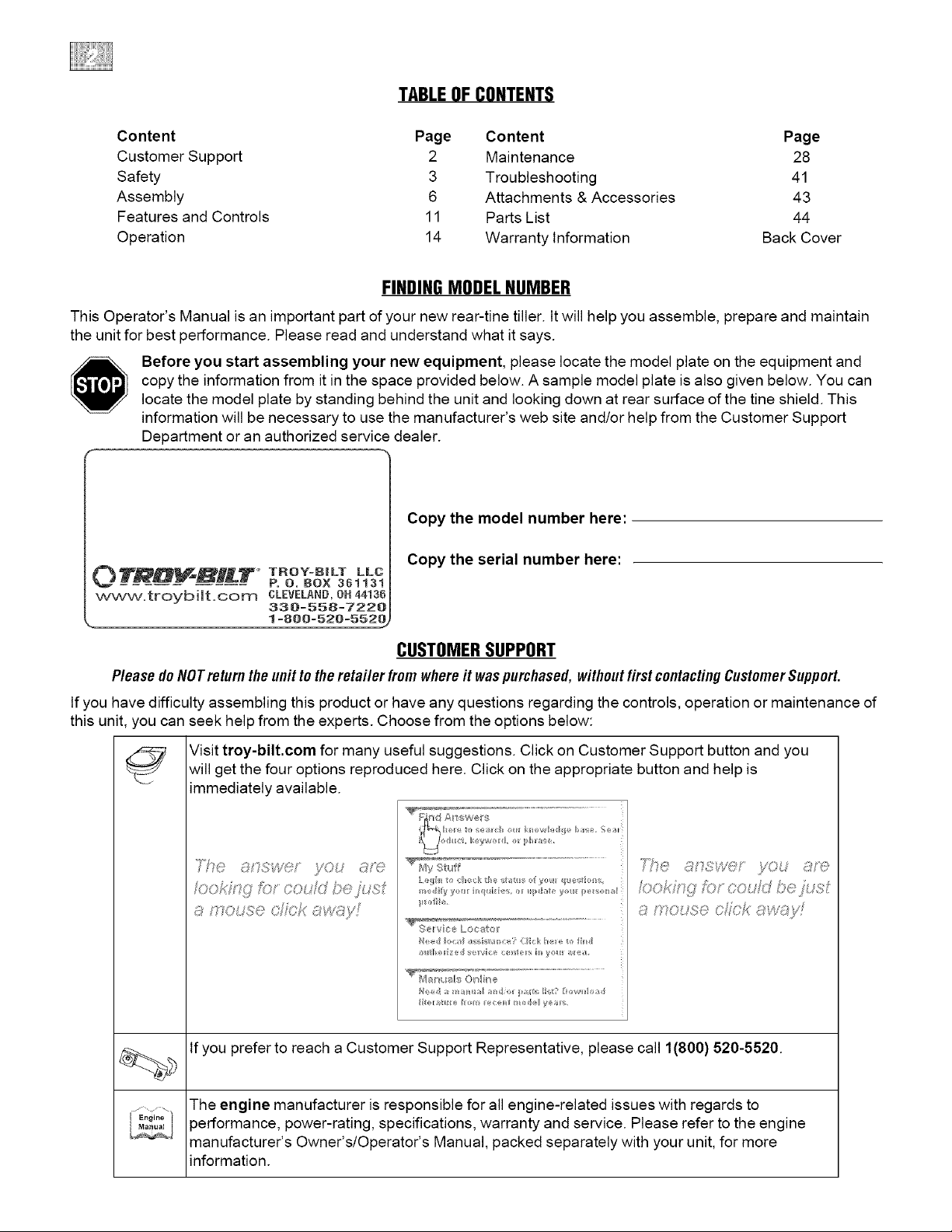
Before you start assembling your new equipment, please locate the model plate on the equipment and
copy the information from it in the space provided below. A sample model plate is also given below. You can
locate the model plate by standing behind the unit and looking down at rear surface of the tine shield. This
information will be necessary to use the manufacturer's web site and/or help from the Customer Support
Department or an authorized service dealer.
Copy the model number here:
Copy the serial number here:
O'_,_,_,_X_" TROY-B|LT LL(
www.troybiJt.oom CLEVELAND,0H44136
_. 1 =800=520=552@
P. O. BOX 361131
330=558=7220
CUSTOMERSUPPORT
Pleasedo NOTreturnthe unit to the retailer from where it waspurchased,without first contactingCustomerSupport.
If you have difficulty assembling this product or have any questions regarding the controls, operation or maintenance of
this unit, you can seek help from the experts. Choose from the options below:
Visit troy-bilt.com for many useful suggestions. Click on Customer Support button and you
will get the four options reproduced here. Click on the appropriate button and help is
immediately available.
JO; c _i
o,,fC ,,
,C GW@¢' ./OL _ '0
_ /,. ,# )'{: J . >_:?
_ Y/"0 ,h;;!:_:@OJf3_;ss;4Is,,, "
7i;,C ........................................
EnOine
If you prefer to reach a Customer Support Representative, please call 1(800) 520-5520.
The engine manufacturer is responsible for all engine-related issues with regards to
performance, power-rating, specifications, warranty and service. Please refer to the engine
manufacturer's Owner's/Operator's Manual, packed separately with your unit, for more
information.
Section
Safety AmertSymbem
This machine meets voluntary safety standard B71.8
- 1996, which is sponsored by the Outdoor Power
Equipment Institute, Inc., and is pubfished by the
American National Standards Institute.
,_ This is asafetyalertsymbol. It is used inthis
Failureto obeysafety messagescould resultin personal
injury or property damage.
1. Carefullyreadthis Owner'sManual, the
separateEngineOwner's Manual,and any
other literature you mayreceive.Bethor-
oughly familiar with the controls and the
proper useof the tiller and itsengine.
Know how to stop the unit and disengage
the controls quickly.
2. Neverallow children to operatethe
tiller. Neverallow adults to operate the
tilier without proper instruction.
3.Keepthe areaof operation clearof alI
persons, particulariy chiidren and pets.
4, Keepin mind that the operator or user
is responsible for accidentsor hazards
occurring to other people,their property,
andthemselves.
1, Thoroughly inspect the areawhere the
tiller isto be usedand removealIforeign
objects.
2. Putthe Wheelsfrines/PTO Drive Lever
into NEUTRALbeforestarting the engine.
3. Do not operatethe tiiier without
wearingadequateoutergarments. Avoid
loose garments or jeweirythat could get
caught in moving parts.
4. Do not operatethe tiiier when barefoot
or wearingsandals, sneakers,or fight
footwear. Wear protective footwear that
wiii improve footing on slippery surfaces.
5, Do nottiii near underground electric
cabies,teiephoneiines, pipes or hoses. If
in doubt,contactyour telephoneor utility
company.
manuaiandonthe unit to alert youto
potential hazards. Whenyou seethis symbol,
readand obeythe messagethat foliows it.
6, Warning: Handlefue!with care;it is
highly flammable andits vaporsare
explosive. Besureto takethe following
precautions:
a. Storefue! incontainers specifically
designedfor this purpose.
b. The gascap shall never beremoved
or fue!addedwhiie the engine is
running. Allow the engineto cooI
for severalminutes before adding
fuel.
¢. Keepmatches,cigarettes, cigars,
pipes, openflames, and sparks
away from the fuettank and fueI
container.
d. FiiifueItankoutdoors with extreme
care. Neverfill fueI tank indoors.
Usea funnel orspout to prevent
spiiiage.
e. Replaceali fue!tank and container
caps securely.
f. If fuei isspiiied, do not attemptto
start the engine, but movethe
machineaway from the areaof
spiiiage and avoid creating any
source of ignition until fuel vapors
havedissipated.
7. Nevermakeadjustments whenengine
is running (unless recommendedby
manufacturer).
1. Donot put hands or feet nearor under
rotating parts. Donot aiiow handsor any
other part ofthe body or clothing nearthe
rotating tines or nearany other moving
part. Thetines beginto rotateforward
A
The engine exhaust from this productcontains
chemicals known to the State of California to cause
cancer, birth defects or other reproductive harm.
oncethe enginestarts, the Tines/PTO
Ciutch Leveris in the ENGAGEposition,
the Forward Interlock Leversare squeezed
closed and the Wheelsfrines/PTO Drive
Leveris shifted to FORWARD.Thetines
rotate in Reversewhether the Interlock
Leversare closed or open.
2. Exerciseextremecautionwhen on or
crossing graveldrives, walks, or roads.
Stayalert for hidden hazardsor traffic. Do
not carry passengers.
3. After striking a foreign object, stop the
engine, removethe wire from thespark
piug wire and prevent it from touching the
spark piug. ThorougHy inspect the
machinefor any damageand repair the
damagebefore restarting and operating
the machine.
4. Exercisecaution to avoid slipping or
falling.
5. If the unit should start to vibrate abhor-
marly,stopthe engine,disconnectthe
spark piugwire and prevent it from
touching the spark piug, andcheck imme-
diatelyfor the cause.Vibration is
generaiiyawarning of trouble.
6. Stopti_eengine,disconnectthe spark
piug wire and prevent it from touching the
spark piugwheneveryou ieavethe
operatingposition, before uncloggingthe
tines, or when makingany repairs, adjust-
ments or inspections.
7, Takeali possible precautions when
leavingmachineunattended.Stopengine.
Disconnectsparkplug wire andmoveit
away from spark piug. Removeignition
key on electdcstart models
Section1: Safety
8. Beforecleaning,repairing, or inspect=
ing, stop the engineand makecertainatI
moving partshavestopped. Disconnect
the spark piug wire and prevent it from
touching the spark piug to prevent acci=
dentaIstarting.
9. The flap on thetine hood must be
down when operatingthe tiiier, unless
using the Hiiier/Furrowerattachment.
10. Neveruse the tiiier unlessproper
guards, piates,or other safetyprotective
devicesareinplace.
11. Do not run engine in an enclosed
area.Engineexhaustcontains carbon
monoxide gas, a deadlypoison that is
odorless, coloriess, and tasteless.
12. Keepchildren and pets away.
13. Neveroperate thetiiier underengine
power if the WheeISpeedLeveris inthe
FREEWHEELposition. In FREEWHEEL,
the wheels wiii not hold thetiiier backand
the revoiving tines could propei the tiiier
rapidly, possibtycausingioss of controi.
AIwaysengagethe WheetSpeedLever in
either FASTor SLOWposition before
starting the engineorengagingthetines
with the WheeIs/Tines/PTODrive Lever.
14. Be aware that the tiller may unexo
pectedlv bounce upward or jamp
forward ifthe tines should strike
extremely hard packedsoil, frozen
ground, or buried obstacles like large
stones, roots, or stumps, ff in doubt
about the tilling conditions,always use
the following operating precautions to
assist you in maintaining control of the
tiller:
a. Walk behind and to one side of the
tiller, using one handon the han-
dlebars. Relax your arm, bnt rise a
secnre handgrip.
b. Use shallower depth regulator
settings, working gradually deeper
with each pass.
c. Use slower wheel, tine and engine
speeds.
d. Clear the tilling area of all large
stones, roots and other debris.
e. Avoid using downward pressureon
handlebars.If need be, use slight
npward pressure to keep the tines
from digging too deeply.
f. Before contacting hard packedsoil
at the endof a row, reduce engine
speed and lift handlebarsto raise
tines out of the soil.
g. Jn an emergency, stoptines and
wheets byshifting the
WheelsiTinesiPTO Drive Lever
intoNEUTRAL.tf you can not
reach the leveror havelostcontrom
of the tiller, let go of the handle=
bars and aHcontroms,go not
attempt to restrain the tiller.
15. Donot overioadthe tiiier's capacity by
attempting to till too deeplyat too fast a
rate.
16. Neveroperatethe tiller at high
transport speedson hard or slippery
surfaces. Look behindandusecare when
backing up.
t7. Donot operatethetiiier on aslope
that istoo steep for safety. Whenon
slopes, slow down andmakesure you
havegood footing. Neverpermit the tiiier
to freewheel down slopes.
18. Neverallow bystandersnearthe unit.
19. Only useattachmentsandaccessories
that areapproved by the manufacturer of
the tiller.
28. Usetiiier attachments and acces-
sories when recommended.
21. Neveroperatethe tiller without good
visibility or iight.
22. Neveroperatethe tiiier if you are
tired, or underthe influence of alcohol,
drugs or medication.
23. Operatorsshali not tamper with the
engine-governor settings on the machine;
the governor controis the maximum safe
operatingspeedto protect the engineand
ali moving partsfrom damagecausedby
overspeed. Authorized service shail be
sought if a problemexists.
24. Donot touch engineparts which may
behot from operation. Letpartscool
downsufficiently.
25. POBON/OANGER--CAUSES
SEVEREBURNS.Thebattery on electric
start models contains suifudc acid. Avoid
contact with skin, eyesor clothing. Keep
out of reachof children.
Antidotes:
External- Flushimmediately with lots of
water.
Internal- Drink largequantities of water
or milk. Follow with milk of magnesia,
beateneggs orvegetableoil. Calla
doctor immediately.
Eyes- Fiushwith water for 15 minutes.
Getprompt medicai attention.
26. DANGER=BATTERIESPRODUCE
EXPLOSIVEGASES. Keepsparks, flame
or smoking materiaisaway. Ventilate
whencharging battery or using inan
enctosedspace. Alwayswear safety
goggteswhen working near battery.
27. Pieaseremember:Youcanalways
stop thetines and wheels by releasingati
controis, or by moving the ignition switch
and/orthrottle control lever on the engine
to OFFor STOP.
28. To ioador unloadthetiller, seethe
instructions in Section4 of this Manual.
29. Useextreme caution when backing or
puliing the machinetowards you.
30. Startthe engine carefuiiy according to
instructions and with feet well awayfrom
the tines.
31. Neverpick up or carry a machine
whiiethe engine is running.
32. When ioading or unioadingthe tiller,
alwaysdisengagetines andusesiower
wheelandenginethrottle speeds. Use
sturdy ramps wideandstrong enoughto
easiiysupport the tiiier (280-to-325 ibs.
dependingon model) and operator.
Nevergo down ramps in FORWARD
drive--the tiiier couid tip forward,
exposingyou to the tines (which should
be disengaged). Always useREVERSE
driveand backdown ramps. Togo up
ramps, use FORWARDdrive and follow
the tiller.
33, The ForwardInterlock SafetySystem
should betested for correct functioning
everytime the tiller or PTOpower unit is
used. SeeSection 4 in this Manual.
34. If using the optional DozerBlade,
either removethe tine attachment, or
disengagethe tines with the Tines/PTO
CiutchLever. Revolvingtines are
dangerous.
Section1: Safety
Maintenance and Sterage
1. Keepthetiiier, attachments and acces-
sories insafeworking condition.
2. Checkali nuts, boits, andscrews at
frequent intervalsfor propertightness to
be surethe equipment is in safe working
condition.
3. Neverstore the tiiier with fue! inthe
fueJtank insidea buiiding where ignition
sources are presentsuch as hot water
and space heaters,furnaces, ciothes
dryers, stoves, electric motors, etc.).
Aiiow engine to cool beforestoring in any
encJosure.
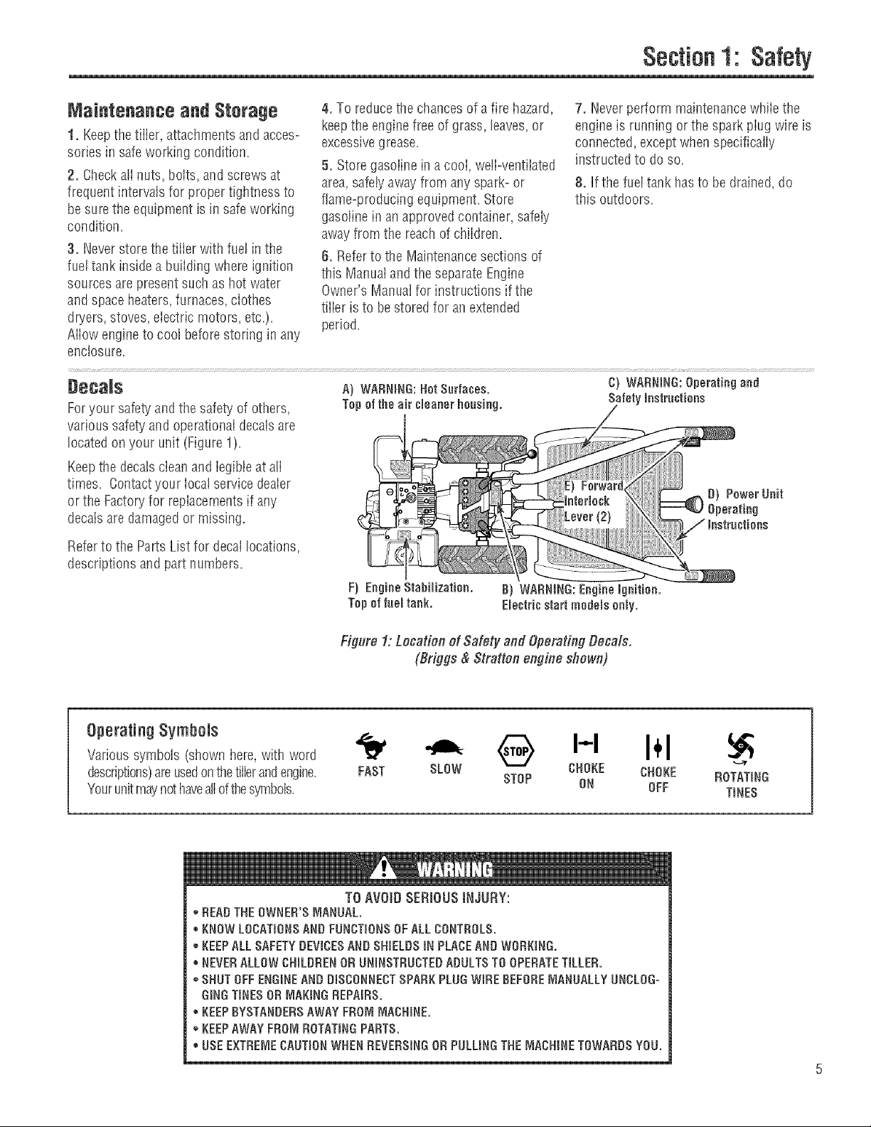
Deca_$ A) WARNmNG:HotSurfaces. C) WARNING:Operatingand
Foryour safetyand the safety of others, Tepeftheair umeanerheusing. Safetymnstruutiens
various safety and operationaldecalsare
located on your unit (Figure 1).
Keepthe decalscleanand legibleat all
times. Contactyour Iocai service dealer
or the Factoryfor repiacementsif any
decals are damagedor missing.
4. To reducethe chancesof a fire hazard,
keepthe enginefreeof grass, leaves, or
excessivegrease.
5. Storegasoiine in a cooi, weJi-ventiiated
area,safetyawayfrom any spark-or
flame-producing equipment. Store
gasolinein anapprovedcontainer, safeiy
awayfrom the reach of chiidren.
6. Referto the Maintenancesections of
this Manuaiandthe separate Engine
Owner's Manualfor instructions if the
tilier is to be stored for an extended
period.
7. Neverperform maintenancewhiiethe
engine is running or the spark piug wire is
connected,exceptwhen specifically
instructed to do so.
8, If the fuel tank hasto be drained, do
this outdoors.
Referto the PartsList for decallocations,
descriptions andpart numbers.
Operating Symbols
Varioussymbols (shown here,with word
descriptions)areusedonthetillerandengine=
Yourunitmaynot haveaiiofthesymbols=
oDEAD THEOWNER'SMANUAL.
KNOW LOCATmONSAND FUNCTmONSOFALLCONTHOLS.
*KEEPALLSAFETYDEVICESAND SHmELDSiNPLACEAND WORKmNG.
NEVERALLOW CHmLDRENOR UNBNSTRUCTEDADULTSTO OPERATETILLED.
*SHUT OFFENGINEAND DmSCONNECTSPARKPLUG WIHEBEFOREMANUALLYUNCLOG=
GiNGTINESOR MAKINGHEPAIRS.
- KEEPBYSTANDERSAWAYFROMMACHINE.
*KEEPAWAYFROM ROTATmNGPARTS.
USE EXTHEI_,_ECAUTmONWHEN HEVEHSmNGOH PULLINGTHEMACHINETOWARDS YOU.
Figure 1: Location of Safety and Operating Decals.
(Briggs & Stratten engine shown)
• @ H I÷1
CHOKE CHOKE HOTATING
FAST SLOW STOP ON OFF TmNES
TO AVOID SERIOUS INJURY:
Section
To preventpersonal injury or property
damage, do not start the engine until
aJJ assembly steps are complete and
you have read and understand the
safety and operatinginstructionsinthis
manual
introduction
Carefuiiyfoiiow these assembiy steps to
correctly prepareyour tiiier for use. It is
recommendedthat you readthis Section
in its entirety beforebeginning assembly.
NOTE:Threedifferent Horse modeltiiiers
are covered in this Manual.Use oniythe
information applicableto your model.
Tiiier engines vary by model.Your engine
mayappear differently than thosefound
in illustrations of this manual.
inspect Unit
h_spectthe unit andcartonfor damage
immediately after deiivery. Contactthe
carrier (trucking company) if you find or
suspect damage. Inform them ofthe
damageandrequestinstructions for fiiing
a claim. To protect your rights, putyour
ciaim inwriting and maiIacopyto the
carrier within 15 days after the unit has
been delivered.Contact us atthe Factory
if you needassistanceinthis matter.
STEP1: Unpacking instructions
NOTE:Donot severelybend any ofthe
control cableson the unit.
1. The tiiier is heavy. Donot attemptto
removeit from tire shipping piatform until
instructed to do so in these Assembly
steps.
2. RemoveaiI ueassembtedparts from
the carton. Thehardware bag is included
in your literature packaging.
3. Checkthat you havethe items iisted
below (contact your local dealeror the
Factoryif any items are missing or
damaged).
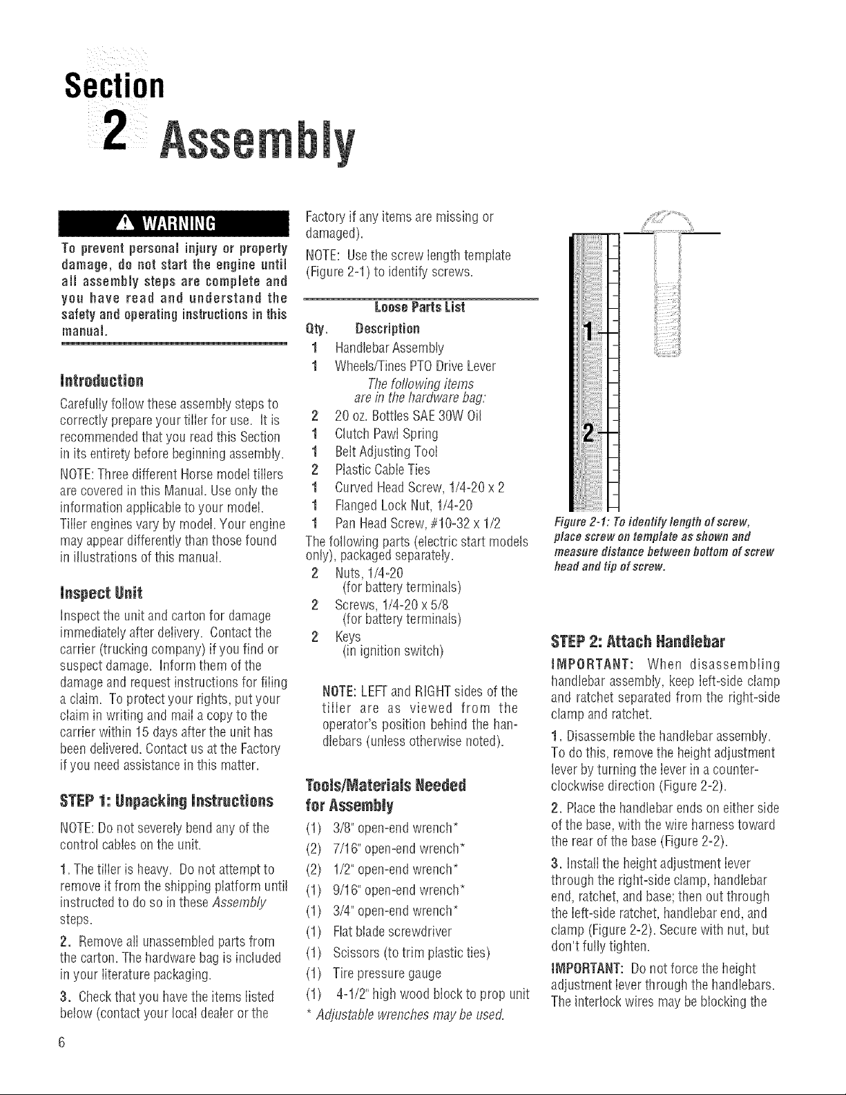
NOTE: Usethe screw iength template
(Figure2-1) to identify screws.
LoosePartsList
Qty. Bescription
1 HandlebarAssembly
1 Wheels/TinesPTODrive Lever
Thefor'towingitems
are in thehardware bag:
2 20 oz. BotttesSAE30W Oil
1 Clutch PawiSpring
1 BeltAdjustingTooI
2 PiasticCabieTies
1 Curved HeadScrew, 1/4-20 x 2
1 FlangedLock Nut, 1/4-20
1 PanHeadScrew,#10-32 x 1/2
The following parts (electric start models
only), packagedseparately.
2 Nuts, 1/4-20
(for battery terminals)
2 Screws, 1/4-20x5/8
(for battery terminals)
2 Keys
(in ignition switch)
NOTE:LEFTand RIGHTsides of the
tiller are as viewed from the
operator's position behind the han=
dlebars (unless otherwise noted).
Toels/MateriaJs Needed
for Assembly
(1) 3/8" open-endwrench*
(2) 7/16" open-endwrench*
(2) 1/2" open-endwrench*
(1) 9/16" open-endwrench*
(1) 3/4" open-endwrench*
(1) Fiatblade screwdriver
(1) Scissors (to trim plastic ties)
(1) Tire pressuregauge
(1) 4-1/2"high wood block to prop unit
* Adjustable wrenchesmaybeused.
Fi lure 2-1: Toidentify lengthof screw,
place screw on template as shown and
measure distance between bottom of screw
head andtip of screw.
STEP2: Attach Nandlebar
JNIPORTANT: When disassembling
handlebar assembly, keep ieft-side clamp
and ratchet separated from the right-side
clamp andratchet.
1. Disassemblethe handlebarassembly.
To do this, removethe heightadjustment
leverbyturning the ieverinacounter-
clockwise direction (Figure2=2).
2. Placethe handlebarends on either side
ofthe base,with the wire harnesstoward
the rearof the base(Figure2-2).
3. Instalithe heightadjustment iever
through the rigirt-side clamp, handlebar
end, ratchet,and base;then out through
the left-side ratchet,handlebarend,and
clamp (Figure2=2).Securewith nut, but
don't fully tighten.
t_IPORTANT: Do not force the height
adjustment ieverthrough the handlebars.
The interlock wires maybeblockingthe
leverandcould bedamaged.You may
gentiy movethe wires aside if this
condition occurs.
4. Raisehandlebars to one of two height
settings andtiglrten the height adjustment
lever. Also, makesureali other mounting
hardware is securelytightened.
Left-Side
Clamp
and Nat
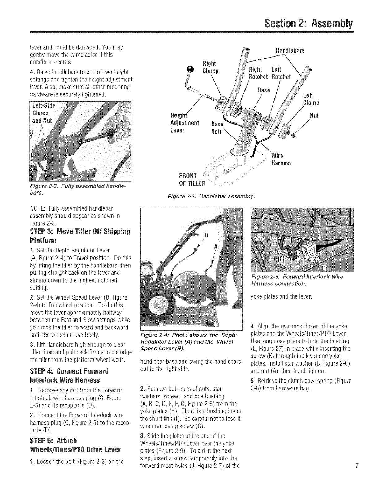
Figure 2=3. Fully assembled handle-
bars.
Section2: Assembly
Right
Clamp
Left
Clamp
Nat
Wire
Harness
FRONT
OFTILLER
Figure 2-2. Handlebar assembly.
NOTE:Fullyassembledhandlebar
assembly should appearas shown in
Figure2=3.
STEP3: Meve Tiller Off Shipping
Piatferm
1. Setthe DepthRegulator Lever
(A, Figure2=4)to Travelposition. Dothis
by lifting the tiiier bythe handiebars,then
puiiing straight back on the ievm and
siiding down to the highest notched
setting.
2. Setthe WheetSpeed Lever(B, Figure
2=4)to Freewheelposition. To do this,
movethe ieverapproximately halfway
betweenthe Fastand Siow settingswhiie
you rockthe tiiim forward andbackward
untilthe wheeis movefreely.
3. Lift Handlebarshigh enoughto ciear
tiiier tines and pull back firmty to dislodge
the tiller from the platform wheel wells.
STEP4: Cenneet Ferward
Figure2-4: Photo shows the Depth
Regulator Lever (A) and the Wheel
Speed Lever (B).
handIebarbaseand swing the handlebars
out to the dglrt side.
interlock Wire Harness
1. Removeany dirt from the Forward
Interlock wire harness plug (C, Figure
2=5)and its receptacle(D).
2. Connectthe ForwardIntmiock wire
harness plug (C,Figure2=5)to the recepo
tacle (D).
STEP5: Attach
Wheels/Tines/PT8 Drive Lever
1. Loosenthe bolt (Figure2=2)on the 7
2. Removeboth sets of nuts, star
washers, screws, and one bushing
(A, B, C, D, E,F,G, Figure2=6)from the
yoke piates (H). Thereis a bushing inside
the si_ortlink (i). Becarefuinot to loseit
when removing screw (G).
3. Siide the ptatesat the end of the
Wheeis/Tines/PTOLeveroverthe yoke
plates (Figure2-9). To aidin the next
step, insert ascrew temporarily into the
forward most holes (J, Figure2=7)of the
Figure 2=& Forward Interlock Wire
Harness connection.
yoke plates and the lever.
4. Align the rear most holes of theyoke
platesand the Wheets/Tines/PTOLever.
Uselong nosepiiers to hold the bushing
(L, Figure 27) in placewhile inserting the
screw (K) througtl the lever andyoke
plates.Install star wasller (B, Figure2=6)
and nut (A), then handtighten.
5. Retrievethe clutch pawl spring (Figure
2=8)from hardwarebag.
Section2: Assembly
Removethe temporary screw (J, Figure
2=7)from the forward holes andmovethe
Wheelsffines/PTO Lever fuliy forward.
[nstalI the wider hook end of the dutch
pawt spring (M, Figure2=8)down into the
smaii holeatthe end of the handle. Use
piiers to insertthe other endinto the hole
in the long link bar (N).
NOTE:Do not bend or overstretch the
spring while instailing.
6. Pull the Wheets/Tines/PTOLeverback
to align the forward most holes (O,Figure
2=9)in the yoke plate with the holesin the
lever plates. Also align the bushing that is
insidethe short link bar (P). [nstalI the
screw, star washer, and nut, then tighten
securely.
Securelytighten all other hardware (Q,R,
Figure2=9). Also ensurethat the spring
(S) is properly seatedat both ends.
Completedassembly should appearas
illustrated in Figure2-9.
7. Test the operation of the
Wheets/Tines/PTOLever. Pushthe iever
down until it engagesinthe Forward
position. The clutch roller (T,Figure2o
10) must rest beneaththe adjustment
block (U). Next, movethe iever up to the
Neutral position. The clutch rolier (T,
Figure2=11)shouid reston the faceof the
adjustment block (U). To test Reverse,iift
and hoid the iever aii the way up in
Reverseposition, then iet it go. Thelever
should automaticaliy return to the Neutrai
position (Figure2=11). If not, do not use
the tiiier. Seeyour local authorized dealer
or carlthe FactoryTechnicalService
Departmentfor instructions.
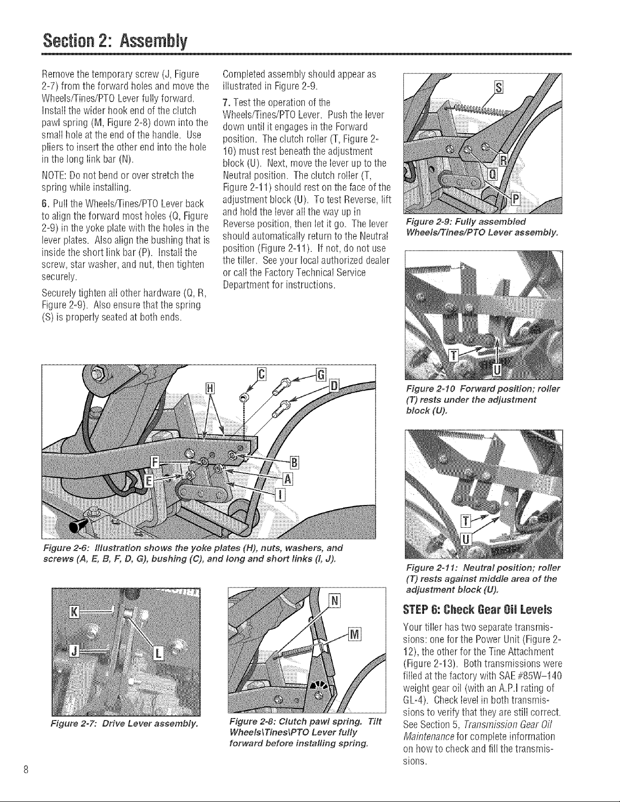
Figure 2-9: Fully assembled
Wheels/Tines/PTO Lever assembly.
Figure 2=6: Illustration shows the yoke plates (H), nuts, washers, and
screws (A, E, B, F, D, G), bushing (C), and long and short finks (t, J).
Figure 2=7: Drive Lever assembly.
Figure 2=8: Clutch pawl spring. Tilt
WheelslTineslPTO Lever fully
forward before installing spring.
Figure 2=10 Forward position; roller
(7")rests under the adjustment
block (U).
Figure 2=11: Neutral position; rofler
(T) rests against middle area of the
adjustment block (U).
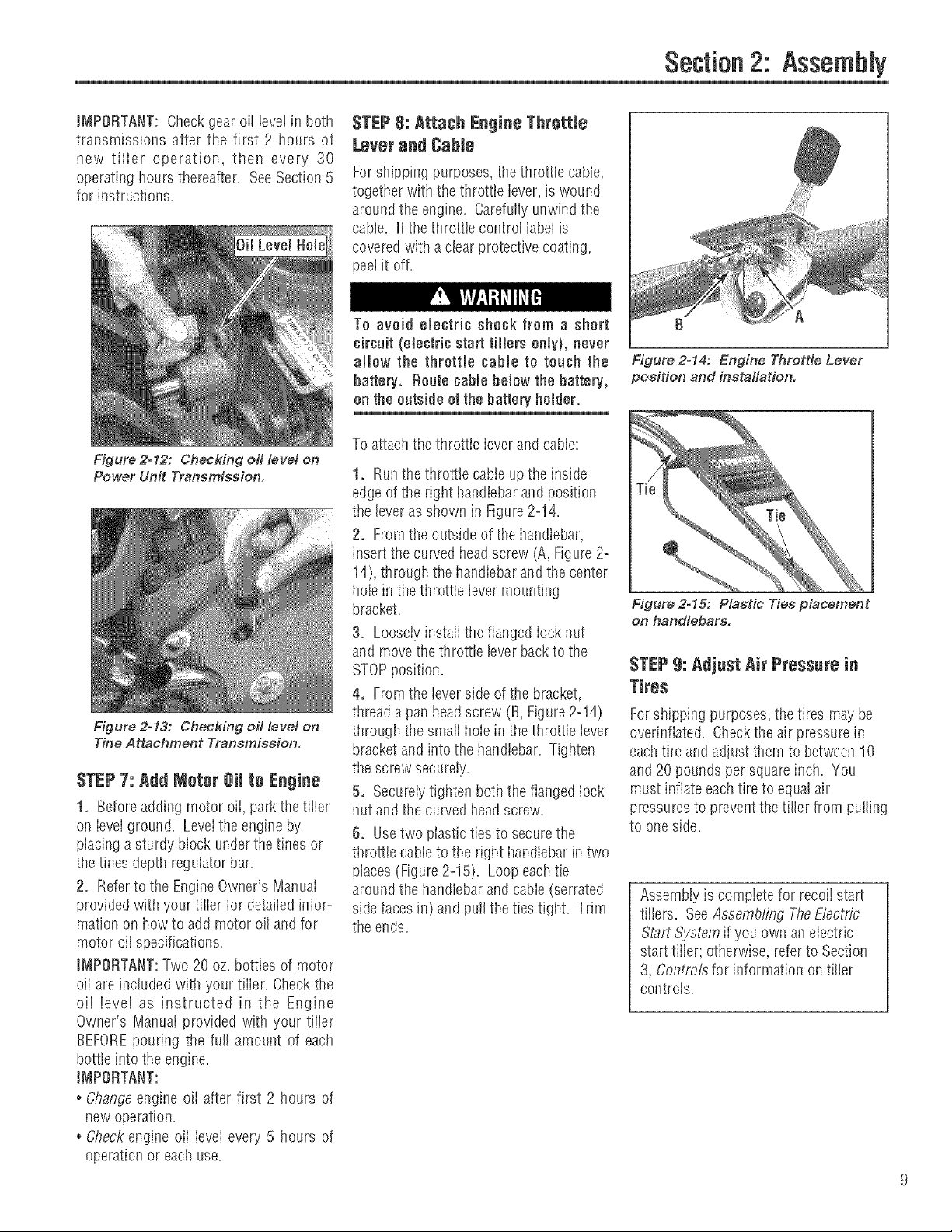
STEP6: CheckGearOil Levels
'four tiller hastwo separatetransmis=
sions: one for the PowerUnit (Figure 2-
12), the other for the TineAttachment
(Figure2-13). Bothtransmissions were
fiiied at the factory with SAE#85W-140
weight gear oil (withanA.PJ rating of
GU4). CheckieveIin both transmis-
sions to verify that theyarestiii correct.
SeeSection5, TransmissionGearOff
MaflTtenancefor compiete information
on howto checkandfill the transmiso
sions.
Section2: Assembly
iMPORTANT: Checkgear oii ievet in both
transmissions after the first 2 hours of
new tiiier operation, then every 30
operating hours thereafter. SeeSection5
for instructions.
Figure 2=12: Checking oil level on
Power Unit Transmission.
Figure 2o13: Checking oil level on
Tine Attachment Transmission.
STEP7: Add Motor Oil to Engine
1. Beforeadding motor oii, park thetiller
oil ieveiground. Levelthe engine by
placing asturdy block underthetines or
the tines depth regulator bar.
2. Referto the EngineOwner's ManuaI
provided with your tiiier for detaiiedinfor-
mation onhow to add motor oil and for
motor oilspecifications.
IMPORTANT:Two 20 oz. bottles of motor
oii areincluded with your tiiier. Checkthe
oii ievei as instructed in the Engine
Owner's Manual provided with your tiiier
BEFOREpouring the full amount of each
bottle into the engine.
iMPORTANT:
° Changeengine oil after first 2 hours of
new operation.
. Checkengine oii ieve! every 5 hours of
operation or each use.
STEP8: Attach Engiee Throttle
Lever and Cable
Forshipping purposes,the throttie cabie,
together with the throttie iever, is wound
around the engine. Carefuiiyunwind the
cable. If the throttle controi iabetis
covered with aclearprotective coating,
peel it off.
To avoid electric shock from a short
circait (electric start tiJJers only), never
allow the throttle cabte to roach the
battery. Route cabte below the battery,
on the outside of the batteryholder.
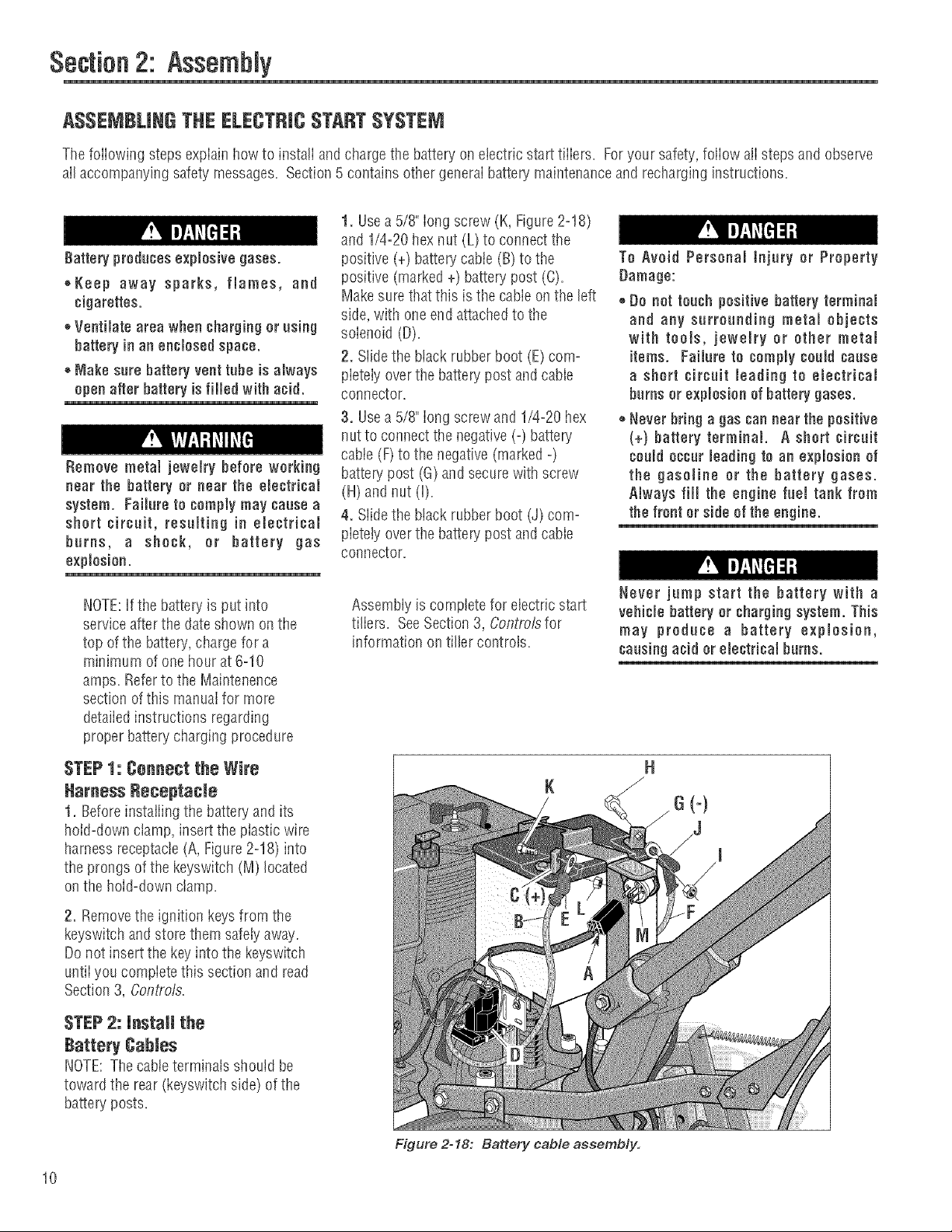
To attach thethrottle leverand cable:
1. Runthe throttle cableupthe inside
edge of the right handlebarand position
the lever as shown in Figure2=14.
2. Fromthe outside of the handlebar,
insert the curved headscrew (A,Figure2=
14),through the handlebarand the center
hole in thethrottie levermounting
bracket.
3. Loosely instaii the flanged iocknut
and movethe throttle leverbacktothe
STOPposition.
4. Fromthe leverside of the bracket,
thread a pall headscrew (B, Figure 2=14)
through the smaiihoiein the throttle iever
bracket and into the handlebar. Tighten
the screw securely.
5. Secureiytighten both theflanged lock
nut and the curvedheadscrew.
6. Usetwo plastic tiesto securethe
throttle cableto the right handlebar intwo
places (Figure2=15). Loop eachtie
around the handlebar and cable (serrated
side faces in) andpulIthe ties tight. Trim
the ends.
f} A
Figure 2-14: Engine Throttle Lever
position and installation.
Figure 2o15: Plastic Ties placement
on handlebars.
STEP9: Adjust Air Pressurein
Tires
Forshipping purposes,the tires maybe
overinflated. Checkthe air pressure in
eachtire and adjust themto between10
and 20pounds per squareinch. You
must inflate each tire to equalair
pressuresto prevent thetiller from pulling
to one side.
Assembiy is compiete for recoiistart
tiilers. SeeAssembling TheElectric
Start System if you own an electric
start tiller; otherwise, refer to Section
3, Controlsfor information oil tiller
controls.
Section2: Assembly
ASSEMBLINGTHE ELECTRICSTARTSYSTEM
ThefoiiowJngsteps expiaiu howto Jnstaliandchargethe battery on electrJcstart tJiiers. Foryour safety',foliow alisteps and observe
all accompanying safety messages=Section5 contains other generalbattep/maintenance and recharginginstructions=
1. Usea 5/8" long screw (K, Figure2=18)
and 1/4=20hexnut (L)to connectthe
Battery producesexplosive gases.
++Keep away sparks, flames, and
cigarettes.
++Ventilate area when chargingor using
battery in an enclosed space.
®Make sure battery vent tube is always
openafter battery is filled with acid.
Remove metal jewemrybefore working
near the battery or near the electrical
system. Failure to comply may cause a
short circuit, resulting in emectfical
burns, a shock, or battery gas
explosion.
positive (+) battery cabte(B)to the
positive (marked +) battery post (C).
Makesurethatthis is the cabie on the left
side, with oneend attachedto the
solenoid (D).
2. Slidethe black rubberboot (E)corn=
pietely overthe batterypost and cable
connector.
3. Usea 5/8" iong screwand 1/4=20hex
nut to connectthe negative(-) battep/
cable (F)to the negative (marked-)
batte_' post (G) andsecurewith screw
(H)andnut (I)=
4. Slidethe black rubberboot (J) corn=
pietetyoverthe battery post and cable
connector.
To Avoid Personal tnjury or Property
Damage:
+Do not touch positivebattery terminal
and any surrounding metal objects
with tools, jewelry or other metai
items. Failure to comply could cause
a short circuit leading to electrical
burns or explosion of battery gases.
++Never bring a gas can near the positive
(+) battery terminal. A short circuit
could occur leading to an explosion of
the gasoline or the battery gases.
Always fill the engine fuel tank from
the front or side of the engine.
NOTE:Ifthe battery is put into
serviceafterthe dateshown on the
top ofthe battery,charge for a
minimum of onehourat 6=10
amps. Referto the Maintenence
section of this manualfor more
detailedinstructions regarding
proper batterycharging procedure
STEP1: Connect the Wire
Harness Beeeptacie
t. Beforeinstaiiing the batteryand its
hold-down clamp, insertthe plastic wire
harness receptacle(A,Figure2-18)into
the prongs of the keyswitch (M) located
on the hoW-downctamp.
2. Removethe ignition keysfrom the
keyswitch and store themsafelyaway.
Donot insert the keyinto the keyswitch
untiiyou compietethis section and read
Section 3, Contro/s.
STEP2: install the
Battery Cables
NOTE:The cableterminals should be
toward the rear (keyswitch side) of the
battery posts.
Assembly is complete for electric start
tiliers. SeeSection 3, Controlsfor
information on tiller controls.
Never jump start the battery with a
vehiclebattery or chargingsystem. This
may produce a battery explosion,
causing acid orelectrical burns.
10
Figure 2o18: Battery cable assembly.
Section
3 =ea u
Before operating your machine,
¢arefuJJy read and understand aJJ
safety, controls, operating instructions
in this Manual, the separate Engine
Owner's Manual and on the decals on
the machine.
Failure to fellow these instructionscan
result inseriuus persunalinjury.
Jntreduetion
This section describes the location and
function of the controls andfeatures on
your tiiier. Referto Section 4, Operation
for detaiiedoperating instructions.
Practiceusingthese controis, with the
engine shut off, untiiyou completely
understandthe operation ofthe controls
and feelconfident with eachof them.
iMPORTANT:Referto the separateengine
manufacturer's Engine Owner's Manuai
for information about the controls on the
engine.
NOTE:Aiireferencesto ieft,right, front
and rearof the machineare basedon a
position behindthe handiebarsandfacing
forward.
PTO Attachments Feature
In addition to powerful tiiiing capabiiity,
you can quickly convert your machine
into a PTO(PowerTake=Off)PowerUnit
that is capable of towing or powering
various TROY-BILTattachments,
You canaccessthis capabiiity by
removing the tines attachment (powered
bythe PTOPower Unit). The PTOPower
Unit isthen avaiiabtefor enginepowered
attachments,or for puiiing ortowing non-
poweredattachments. SeeSection 4,
PTOPower Unitfor detaiiedinformation
on instaiiingand operatingTROY-BILT
PTOattachments.
Wheelo/TiueoiPTODrive Lever
Usethe VVheets/Tines/PTODrive Lever (A,
Figure3-1) to engageand disengage
powerto thetransmission.
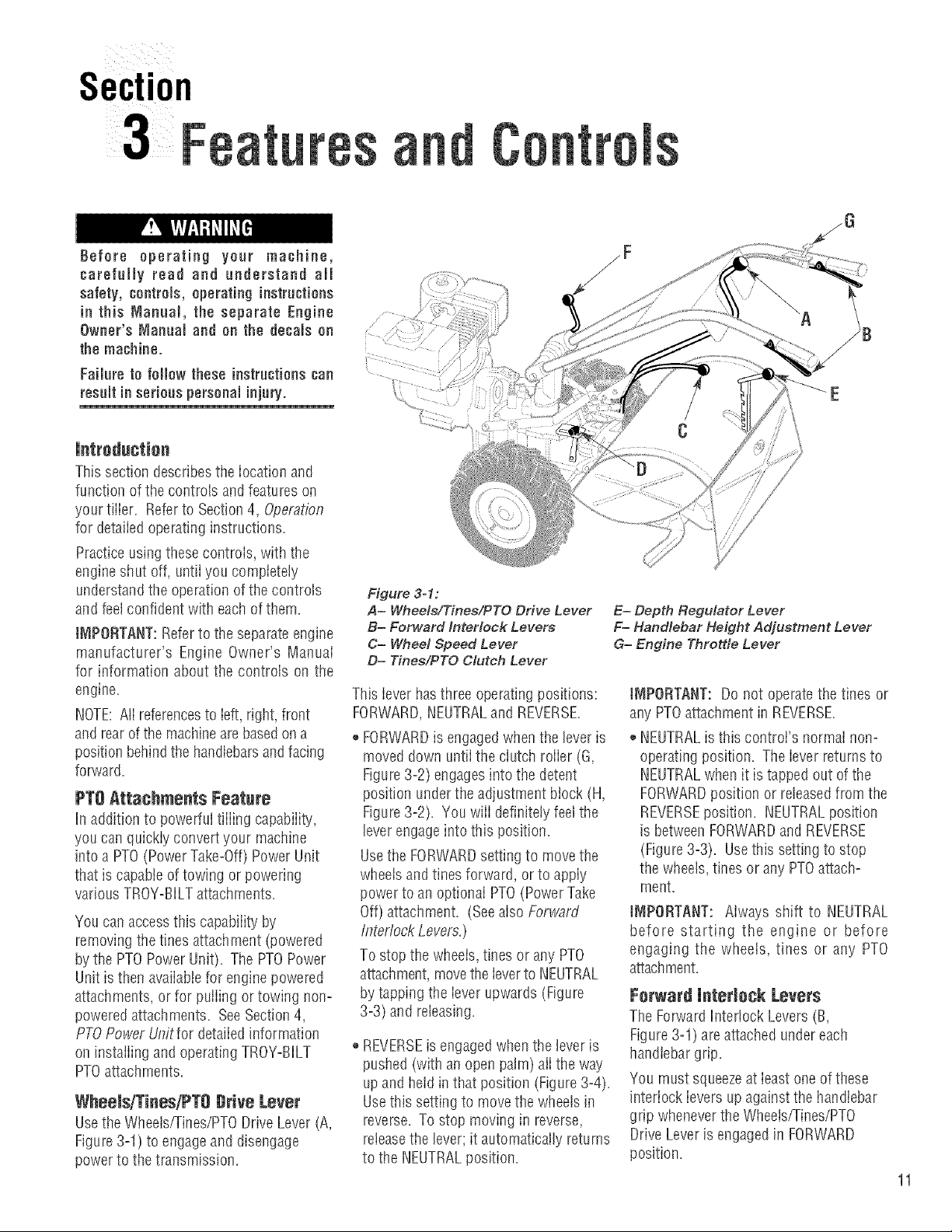
Figure 3-1:
A= Whee/s/Tinee/PTO Drive Lever
B= Forward Interlock Levers
C= Wheel Speed Lever
D= Tines/PTO Clutch Lever
This lever has three operating positions:
FORWARD,NEUTRALand REVERSE.
,, FORWARDis engagedwhenthe leveris
moved down untilthe clutch roller (G,
Figure3-2) engagesinto the detent
position underthe adjustment block (H,
Figure3-2). You wilI definitely feelthe
leverengageinto this position.
Usethe FORWARDsetting to movethe
wheels andtines forward, or to apply
power to an optional PTO(Power Take
Off) attachment. (Seealso Forward
Interlock Levers.)
To stop the wheeis,tines or any PTO
attachment,movethe Ieverto NEUTRAL
by tapping the iever upwards(Figure
3=3)and releasing.
REVERSEis engagedwhenthe lever is
pushed (with an open palm) aiithe way
up and heid inthat position (Figure 3-4).
Usethis setting to movethe wheetsin
reverse. To stop moving in reverse,
reteasethe lever; it automatically returns
to the NEUTRALposition.
/F
E= Depth Regulator Lever
F= Handlebar Height Adjustment Lever
G= Engine Throtde Lever
JNIPOflTANT: Do not operatethe tines or
any PTOattachment in REVERSE.
NEUTRALis this control's normai non-
operating position. Theiever returns to
NEUTRALwhen it is tappedout of the
FORWARDposition or releasedfrom the
REVERSEposition. NEUTRALposition
is betweenFORWARDandREVERSE
(Figure3-3). Usethis setting to stop
the wheels, tines orany PTOattach-
ment.
IMPORTANT: Always shift to NEUTRAL
before starting the engine or before
engaging the wheels, tines or any PTO
attachment.
Forward interlock Levers
The Forward h_ter!ockLevers(B,
Figure3-1) areattached undereach
handlebargrip.
You must squeezeat ieastoneof these
interlock ievers up against the handlebar
grip wheneverthe Wheets/Tines/PTO
Drive Leveris engagedin FORWARD
position.
11
Section3: FeaturesandControls
Yer!fy Pos!tion of Clutch Roller
When you sNft between FORWABDI
NEUTRAL and REVERSEI the clutch
roller at the base of the
Wheeb!Tines/PTO Drive Lever should
be pesitiobed as shown in Eigures3_2,
3:3 and 3'4, Verify the position Ofthe
clutch roller as you shift the bver_ If it
is not POSitbnedcorrect!y, contact the
Faptory or see your local authorized Wheel Speed Lever
dealer.
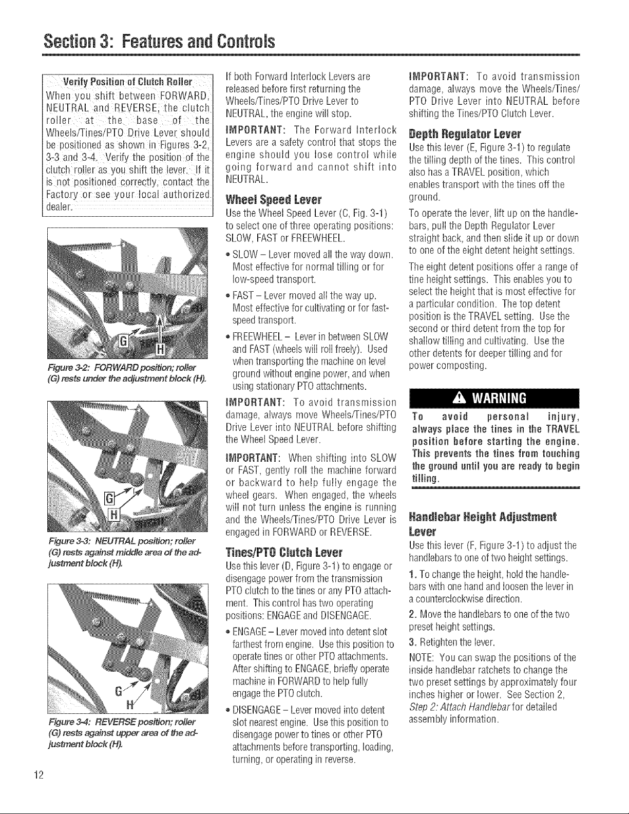
Figure 32: FORWARD pos_on; rotier
(G)rests under the adjustment block (H).
Figure 3-3: NEUTRAL position; relier
(G) rests against middle area of the ado
justment block (H).
Figure 3-4: REVERSE position; relier
(G) rests against upper area of the ad-
justment block (H).
12
If both Forward Interlock Leversare
releasedbefore first returning the
Wheels/rines/PTO Drive Leverto
NEUTRAL,the enginewill stop.
iMPORTANT: The Forward Interlock
Levers are a safety control that stops the
engine should you lose control while
going forward and cannot shift into
NEUTRAL.
Usethe Wheel SpeedLever(C,Fig.3-1)
to select oneofthree operatingpositions:
SLOW,FASTor FREEWHEEL.
* SLOW- LevermovedalIthe waydown.
Most effective for normal tilling or for
low-speedtransport.
®FAST- Lever moved all the way up.
Most effective for cultivating or for fast-
speedtransport.
FREEWHEEL- Leverin betweenSLOW
and FAST(wheelswill rollfreely). Used
whentransporting the machineonlevel
ground withoutenginepower,andwhen
usingstationaryPTOattachments.
IMPORTANT: To avoid transmission
damage, always move Wheels/Tines/PTO
Drive Lever into NEUTRALbefore shifting
the Wheel SpeedLever.
IMPORTANT: When shifting into SLOW
or FAST,gently roll the machine forward
or backward to help fully engage the
wheel gears. When engaged, the wheels
will not turn unless the engine is running
and the Wheets/Tines/PTODrive Lever is
engagedin FORWARDor REVERSE.
TinesiPT8 CJutchLever
Usethis lever(D, Figure3-1) to engageor
disengagepowerfrom thetransmission
PTOclutchto the tines or any PTOattach-
ment. Thiscontrol has two operating
positions: ENGAGEand DISENGAGE.
ENGAGE- Levermovedinto detentstot
farthestfrom engine. Usethis positionto
operatetinesor other PTOattachments.
Aftershifting to ENGAGE,brieflyoperate
machinein FORWARDto helpfully
engagethe PTOclutch.
,, DISENGAGE- Levermovedinto detent
slot nearestengine. Usethis positionto
disengagepowerto tines or otherPTO
attachmentsbeforetransporting, loading,
turning, or operatinginreverse.
IMPORTANT: To avoid transmission
damage, always move the Wheels/Tines/
PTO Drive Lever into NEUTRAL before
shifting the Tines/PTOClutch Lever.
#epth Regalater Lever
Usethis lever (E, Figure3-1) to regulate
the tiiiing depthof the tines. This control
alsohasa TRAVELposition, which
enablestransport withthe tines off the
ground.
To operate the lever, rift up on the handle-
bars, pulIthe DepthRegulatorLever
straight back, and then slide it up or down
to one of the eight detent height settings.
The eight detentpositions offer a rangeof
tine heightsettings. This enabbs you to
selectthe heightthat is most effectivefor
a particular condition. The top detent
position isthe TRAVELsetting. Usethe
second or third detent from the top for
shallow tilling and cultivating. Usethe
other @tents for deepertilling and for
powercomposting.
To avoid personal injury,
always place the tines in the TRAVEL
position before starting the engine.
This preventsthe tines from touching
the gronnd nntil yon are ready to begin
tilling.
Handlebar Height Adjustment
Lever
Usethis lever (F, Figure3-1) to adjustthe
handlebarsto oneoftwo heightsettings.
1, To changethe height, hoidthehandb-
barswithonehandandioosenthe leverin
acounterclockwisedirection.
2. Movethe handiebarsto oneofthe two
presetheightsettings.
3. Retightentheiever.
NOTE:Youcan swapthe positions of the
insidehandlebarratchetsto changethe
two presetsettings by approximately four
inches higiler or iower. SeeSection2,
Step2: Attach Handfebarfor detailed
assembly information.
The tiller handlebars can be swung out
300to the right side for use only with the
PTOChipper/Shredder attachment. This
is done by looseningthe mounting bott
on the handlebar base, Never operate
your tiller or attachments, otherthan the
PTOChipper/Shredder, with the handleo
bars in the right side position. Doing so
could result in unsafe handling and
personalinjury.
Engine Throttle Lever
Usethe throttle lever(G, Figure3-1)to
adjust engine speedaswell asto start
and stop the engine.
Movethe leveraway from the STOP
position before starting the engine.
Enginespeedsare variableand range
betweenthe FASTandSLOW. Usethe
STOPposition to turn the engine off.
NOTE:A secondarythrottle leveris
located on the front ofthe 8HPandIOHP
engines. AseparateOn/Offswitch may
alsobeavailableontheengine. (See
EngineOwner'sManualfor information.)
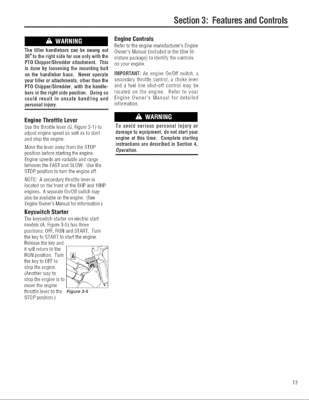
Keyswitch Starter
Thekeyswitchstarter on electricstart
models (A, Figure3-5) hasthree
positions: OFF,RUNand START. Turn
the keyto STARTto start the engine.
Releasethe keyand
it wilI returnto the
RUNposition. Turn
the keyto OFFto
stop the engine,
(Another way to
stop the engine is to
move the engine
throttle leverto the Figure 3-5
STOPposition,)
Section3: FeaturesandControls
Engine Controls
Referto the enginemanufacturer's Engine
Owner's Manual (included in thetiller lit-
erature package)to identify the controls
on your engine.
IMPORTANT:An engine On/Offswitch, a
secondary throttle control, a choke lever
and a fue! iine shut-off controi may be
located on the engine, Refer to your
Engine Owner's Manual for detailed
information.
To avoid serioae personal injury or
damage to equipment, do not start your
engine at this time. Complete starting
instructionsare desoNbed in Section 4,
Operation.
13
Section
Before operating your machine,
carefullyread and understand all safety
(Section 1), ¢ontrots (Section 3) and
operating instrnotions (Section 4) in
this Manual, in the separate Engine
Owner's Manual and on the deoamson
themachine.
FaUnre to follow these instructionscan
resnlt inserious personaminjury,
Readthis Section ofthe manual
thoroughiy beforeyou start the engine.
Then,take the timeto famiiiarizeyourself
with the basic operation of the tilbr
before using it in your garden. Findan
open, level areaand practice usingthe
tiibr controis without the tines engaging
the soii (put tines in Travelsetting--
Section 3, Depth RegulatorLeve,9. Onty
after you've becomecompieteiy famiiiar
with the tflier shoutd you begin using it in
the garden.
Your tiller and its optional PTO Power
Unit attachments are capable of
oansingsefions injury to nntrained or
carelessoperators.
To avoid serious personal injury or
property damage, read the Owner's
Manual that is provided with any
optionaJ accessories or attachments
before using the tiller or PTO Power
Unit.
Break-in i)peration
Perform the following maintenanceduring
the first hours of newoperation (see
MaflTtenanceSectionin this Manuaiand
maintenanceinformation in the Engine
Owner's Manuai).
1, Changeengineoii after first 2 hours of
newengineoperation.
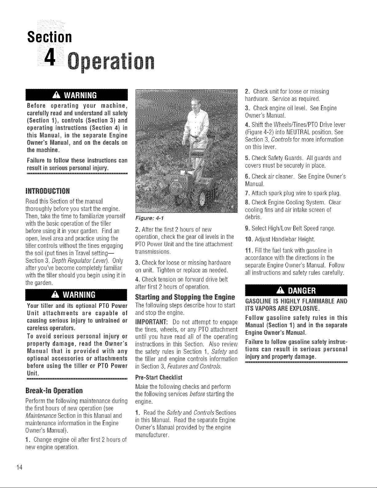
Figure: 4=1
2. After the first 2 hours of new
operation,checkthe gear oiI levelsinthe
PTOPower Unit and the tine attachment
transmissions.
3. Checkfor loose or missing hardware
on unit. Tighten or replaceasneeded.
4. Checktension on forward drivebelt
after first 2 hours of operation.
Starting and Stopping the Engine
Thefollowing stepsdescribehow to start
and stop the engine.
IMPORTANT: Do not attempt to engage
the tines, wheels, or any PTOattachment
untii you have read ali of the operating
instructions in this Section. Atso review
the safety rubs in Section 1, Safety and
the tiller and engine controls information
in Section 3, Featuresand Controls.
Pro=StartChecklist
Makethe following checks and perform
the following services beforestarting the
engine.
1. Readthe Safetyand Confl'otsSections
inthis Manual Readthe separate Engine
Owner'sManuai provided by the engine
manufacturer.
2, Check unit for looseor missing
hardware. Serviceas required.
3, Checkengine oil level. SeeEngine
Owner's Manual.
4. Shift the Wheeis/Tines/PTODriveiever
(Figure4-2) into NEUTRALposition. See
Section3, Controls for more information
on this iever.
5, Check Safety'Guards. AIIguards and
covers must besecurelyin place.
6, Check air cieaner. SeeEngineOwner's
Manual.
7. Attach sparkpiug wire to spark piug.
8, Check EngineCooling System. Clear
cooiing fins and air intakescreen of
debris.
g. Sebct High/Low Belt Speedrange.
10. Adjust HandlebarHeight.
11, FilIthe fuettank with gasolinein
accordancewith the directions in the
separateEngineOwner's Manual. Foliow
alIinstructions andsafetyrules carefully.
GASOUNEIS HIGHLY FLANJNIABLEAND
iTS VAPORSAREE×PLOSIVE.
Follow gasoline safety rules in this
Manual (Section 1) and in the separate
EngineOwner's N_annaJ.
Failure to folJow gasoline safety instruc-
tions can resuJt in serious personal
injnryandproperty damage.
14
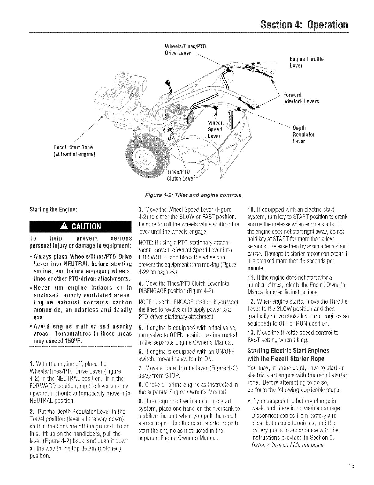
Figure 4-2: Tiller and engine controls.
Section4: Operation
EngineThrottle
Lever
Forward
interlockLevers
Depth
RegaJatar
Lever
Starting the Engine:
To help prevent serious
personalinjuryor damage to equipment:
,_Always place Wheels/Tines/PTO[}rive
Lever into NEUTRAL before starting
engine, and before engaging wheels,
tines orether PTO=dfivenattachments.
,,Never run engine indoors or in
enclosed, poorly ventihted areas.
Engine exhaust contains carbon
monoxide, an odorless and deadly
gas,
,,Avoid engine muffler and nearby
areas. Temperatares in these areas
may exceed150OF.
1. With the engineoff, placethe
Wheets/Tines/PTODrive Lever (Figure
4=2)in the NEUTRALposition. If in the
FORWARDposition, tap the iever sharply
upward, it should automatically move into
NEUTRALposition.
2. Putthe DepthRegulator Leverinthe
Travel position (leveralI the way down)
so that the tines areoffthe ground. To do
this, lift up on the handlebars,pulI the
lever (Figure 4-2) back,and push it down
ali the way to the top detent (notched)
position.
3. Movethe WheelSpeedLever(Figure
4=2)to either theSLOWor FASTposition.
Besureto rolithe wheelswhiie shifting the
leveruntil thewheelsengage.
NOTE:If usingaPTOstationaryattach°
meet,movethe WheelSpeedLeverinto
FREEWHEELandblock the wheelsto
preventthe equipmentfrom moving(Figure
4=29onpage29).
4. MovetheTines/PTOClutchLeverinto
DISENGAGEposition(Figure4=2).
NOTE:UsetheENGAGEpositionifyou want
thetinesto revolveor to applypowerto a
PTO=ddvenstationap./attachment.
5. If engine is equippedwith a fuel valve,
turn valveto OPENposition as instructed
in the separateEngineOwner'sManual.
6. If engine is equippedwith an ON/OFF
switch, move the switchto ON.
7. Moveengine throttie lever (Figure4=2)
away from STOP.
8. Chokeor prime engineasinstructed in
the separateEngineOwner's Manual.
9. If not equippedwith an electric start
system, placeone hand on the fueltankto
stabiiizethe unitwhen you pu!I the recoii
starter rope. Usethe recoii starter ropeto
start the engineasinstructed in the
separateEngineOwner's Manual.
10. If equipped with an electric start
system, turnkeyto STARTpositionto crank
enginethenreleasewhenenginestarts. If
theenginedoesnotstart rightaway,donot
holdkeyatSTARTfor morethana few
seconds. Releasethentry againafterashort
pause. Damageto startermotorcan occurif
itiscrankedmorethan15secondsper
minute.
11. Ifthe enginedoesnotstart aftera
numberoftries,refertotheEngineOwner's
Manualforspecificinstructions.
12. When engine starts, movetheThrottle
Leverto the SLOWposition andthen
graduatiy movechoke iever (onenginesso
equipped) to OFFor RUN position.
13. Movethe throttle speedcontrol to
FASTsetting whentilling.
Starting Electric Start Engines
with the Re€ell Starter Repe
You may,at some point, haveto start an
etectric start engine with the recoii starter
rope. Beforeattemptingto do so,
perform the foiiowing appiicabiesteps:
®Ifyoususpectthe battery chargeis
weak,andthere is no visible damage.
Disconnectcabtes from batteryand
cieanboth cableterminais, and the
batten' posts in accordancewith the
instructions providedin Section5,
BatteryCareand Maintenance.
15
Section4: Operation
Reconnectthe cables and securely
tighten to battery posts. Theenginewiii
rechargethe battery if the battery is still
good.
o If you suspectthe batteris "dead", or if
the batteryis damaged, disconnect,and
remove it. Haveit checkedby a
quaIifiedtechnician.
®If battery hasbeen removed,wrap cable
terminals at endof positive cable with
electricaItapeandsecurethe cableto
the batterybracket.Thiswill prevent
electricaldischarge.
Beforepuffingthe recoil starter rope,
turn the keyswitchto the RUN position.
Move theThrottle Leverawayfrom
STOPposition andset the choke as
applicable.See EngineOwner's Manual.
Cold Weather Operation
Whentemperaturesfail below40% eo
the following s_ensto protectyour
engine ana transmission from _amage:
1. Referto the EngineOwner's Manual
for motor oil specifications for cold
weather operation. Usewinter blend
gasoline
2. Warm up the enginebefore putting it
undera load.
3. Usewinter-blenDgasoline,
4. Usethe correct weight gearoil in PTO
PowerUnit[ransmission.
5. Warm up thetransmission c2earoil as
follows: With engine running, moye
Wheel SpeedLever(Figure4-2) to
FREEWHEEL_thenblock wheelssothey
can't roll, put Tines/PTOClutch Le/or
into DISENBAGE.then squeezeone of
the ForwardInterlock Leversandsnift
the Wheels!Tines!PTODrive Leverto
FORWARD.
6. if wheelsarefrozen to the grounD,
melt ice with warm water.
Stepping the Engine and Tiller
1. Tostop the wheels andtines, movethe
Wheets/Tines/PTODrive Lever into
NEUTRALposition andthen releaseboth
ForwardInterlock Levers.
16
2. Move the engineThrottle Leverto the
STOPposition. Thenonelectric start
models,turn the keyto OFF. Removethe
keyfor safekeeping.
NOTE:Theengine may havea separate
Throttle Control LeverandON/OFFswitch
onthe engine. Thesecontrols can also be
usedto stopthe engine. Seethe Engine
Owner'smanuai for information specific
to your engine.
Operating the Tiller
Whenfirst practicing, keepthe Tines/PTO
CiutchLeverin DISENGAGEposition and
the Wheel SpeedLeverin SLOWposition.
To avoid serious personal injury or
damage to equipment:
,_Always placeWheelsiTiees/PTO Drive
Lever in NEUTRAL before starting
engine, and before engaging wheels,
tines orother PTOattachments.
®Be sure there are no obstacles behind
you before moving inreverse.
* Wheels/TinesiPTO Drive Lever should
automatically return to NEUTRAL
when released from REVERSE
position, tf it does not, move lever to
NEUTRAL manually and discontinue
use until you adjust the lever. See
Seotion 5, Checking and Adjustind
Reverse Drive System.
,,No reverse motion should occur if
Wheels[TinesiPTO Drive Lever is not
held up in REVERSE. See Section 5,
Checkiflg and Adjustind Reverse
Drive System for adjustment steps.
Do not use tiller unless properly
adjusted.
,, Always return to NEUTRALand let all
motion stop before shifting to
FORWARDor REVERSE.
Thefoiiowing pagesprovideguidelines
for using your tiiier effectively and safely
in various gardening applications. Be
sure to readTf/ling Tips& Techniques,in
this Section, beforeyou actually putthe
tines into the soii.
This isa traditional standard=rotating-tine
(SRT)tiiier with forward rotating tines. It
operatesin a compietely different manner
than counter-rotating-tine (CRT)tillers, or
from front-fine tillers.
lVleving the Tiller Forward and Tilling
1. Start the engineandgraduatiyincrease
enginespeedto FAST(seeStarting the
Engine,this Section).
The Forward Interlock Safety System is
designed for the operator'ssafety. Do
not disoonneot or attempt to defeat the
purpose of the system, if the system
malfunctions, immediatelycontactyour
IDeal authorized dealer or the
TROY=BtLTTeohnical Service Depart =
meet for assistance. Do not use the
tiller or the PTO power unit until the
Forward hterlook Safety System is
functioning properly. Always test the
system before asing the tiller or PTO
power anit.
2. Test the Forward Interlock Safety
System. See TestingForward interlock
System,this Section.
Keep away from rotating tines. Rotating
tines will caase injury.
3. When practicing,setthe Depth
Regulator Leverto Travelposition.
Otherwise,set the DepthRegulatorLever
to a desireddepth.
4. MoveTines/PTOClutchLever to
ENGAGEposition if you wantthetines to
turn. If practicing, leavein DISENGAGE.
tNIPORTANT: Do not move Tines/PTO
Ciutch Lever to ENGAGE unless
Wheels/Tines/PTO Drive Lever is in
NEUTRAL Tiller damagemayoccur!
5. To movethe tiller forward andengage
the tines, squeezeand hold eitherForward
Interlock Lever(Figure4-3) against the
handlebargrip, then movethe
Wheels/Tines/PTODrive Leverdown to
FORWARDposition.
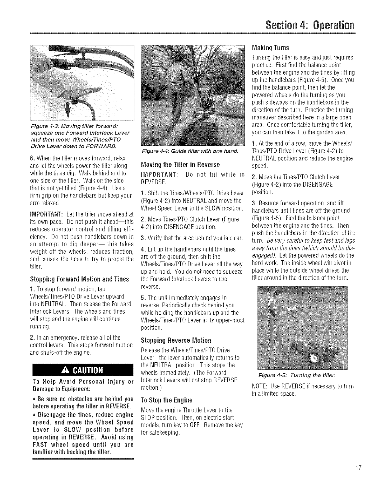
Figure 4=3: Moving tiller forward:
squeeze one Forward interlock Lever
and then move Wheels/Tines/PTO
Drive Lever down to FORWARD.
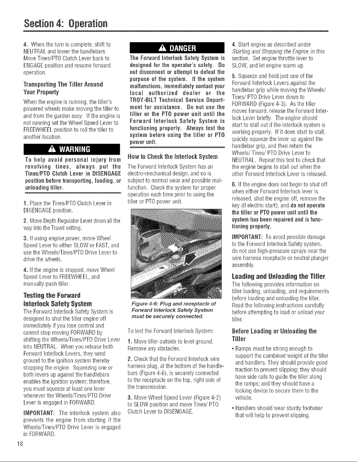
6. Whenthetiller movesforward, reiax
and ietthe wheels power the tiiier along
whiie the tines dig. Walk behind andto
one side of the tifler. Watkonthe side
that is notyettilled (Figure4-4). Usea
firm grip on the handlebarsbut keepyour
arm relaxed,
JNtPORTANT:Letthe tiiier move aheadat
its own pace. Do not push it ahead--this
reduces operator controi and tiiiing effi=
ciency. Do not push handlebarsdown in
an attempt to dig deeper-- this takes
weigilt off the wheels, reduces traction,
and causes the tines to try to propel the
tiller.
Stopping Forward Motion and Tines
1. To stop forward motion, tap
Wheels/Tines/PTODriveLeverupward
into NEUTRAL.Then releasethe Forward
Interlock Levers. Thewheelsandtines
wiii stop and the enginewill continue
running.
2. in an emergency, reieaseaiI of the
controi ievers. This stops forward motion
and shuts-off the engine.
To Help Avoid Personal injury or
Damage to Equipment:
®Be sure no obstacles are behind you
before operatingthe tiller in REVERSE.
® Disengage the tines, reduce engine
speed, and move the Wheel Speed
Lever to SLOW position before
operating in REVERSE. Avoid using
FAST wheel speed until you are
familiar with backing the tiller.
1
Figure 4=4: Guide tMer with one hand.
Moving the Tiller in Reverse
tN_PORTANT: Do not till while in
REVERSE,
1. Shift the Tines/Wheels/PTODrive Lever
(Figure4=2)into NEUTRALand movethe
WheetSpeedLever to the SLOWposition.
2. Move Tines/PTOClutch Lever(Figure
4-2) into DISENGAGEposition.
3. Verify that the areabehindyou is clear.
4. Lift upthe handlebarsuntii tile tines
are off theground, thenshift the
Wheeisffines/PTO Drive Lever aii the way
up andhoW. Youdo not needto squeeze
the Forward Interlock Leversto use
reverse.
5. Theunit immediatelyengages in
reverse.Periodicaliycheckbehind you
whiie hewing the handlebarsupandthe
Wheelsfrines/PTO Leverin its upper-most
position.
Stopping Reverse Motion
Releasethe Wheels/Tines/PTODrive
Lever- the ieverautomaticaiiy returnsto
the NEUTRALposition. Thisstops tile
wheeis immediately. (The Forward
Interlock Leverswill not stop REVERSE
motion.)
To Stop the Engine
Move the engineThrottleLeverto the
STOPposition. Then,on electric start
models, turn keyto OFF. Removethe key
for safekeeping.
Section4: Operation
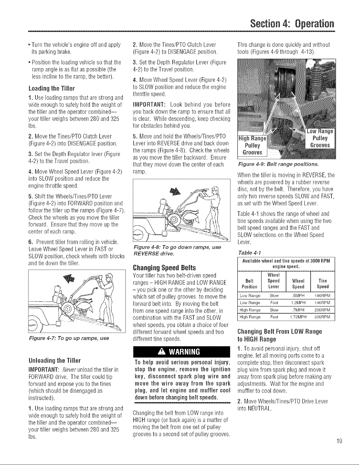
Making Turns
Turningthe tiiier is easyand just requires
practice. First find the balancepoint
betweenthe engineandthe tines by iifting
up the handlebars (Figure4°5). Onceyou
find the balancepoint, then iet the
poweredwheets dothe turning as you
push sideways on the handlebarsin the
direction of the turn. Practicetheturning
maneuverdescribed herein a iarge open
area. Oncecomfortabie turning the tiiier,
you can then take it to the gardenarea.
1. Atthe end of a row, movethe Wheeis/
Tines/PTODrive Lever(Figure4-2) to
NEUTRALposition and reducethe engine
speed.
2. Movethe Tines/PTOClutch Lever
(Figure4-2) into the DISENGAGE
position.
3, Resumeforward operation,andlift
handlebars until tinesareoffthe ground
(Figure4°5). Find the balancepoint
betweentile engine andthe tines. Then
push the handlebarsin the direction of the
turn. Be vely camfuf to keep feet and legs
away from the fines (which should be dis°
engaged). Letthe poweredwheelsdothe
hard work. The inside wheelwiii pivot in
placewhiie the outside wheei drivesthe
tifler around inthe direction ofthe turn.
Figure 4-5: Turning the tiller.
NOTE:UseREVERSEif necessaryto turn
in alimited space.
17
Section4:
4. When the turn is complete, shift to
NEUTRALand lower the handlebars=
Move Tines/PTOCiutcil Leverbackto
ENGAGEposition and resumeforward
operation.
Transporting The Tiller Around
Year Property
Whenthe engine is running, thetiiieSs
poweredwheatsmake moving the tiiier to
and from the gardeneasy. If the engineis
not running set the WheelSpeedLeverto
FREEWHEELposition to roll thetiller to
another location.
To help avoid personal injury from
revolving tines, always pat the
TinesiPTOCtutsh Lever in DISENGAGE
position before transporting, loading,or
unloading tiller.
1. Placethe Tines/PTOClutch Leverin
DISENGAGEposition.
2. MoveDepthRegulatorLeverdownalI the
wayintotheTravelsetting.
3. If using engine powel; move Wheel
SpeedLeverto either SLOWor FAST,and
usethe Wheeis/Tinee/PTODrive Leverto
drivethe wheats.
4. If the engineis stopped, move Wheel
SpeedLeverto FREEWHEEL,and
manually pushtiller.
Tenting the Forward
lnterinsk Safety System
TheForwardInterlock Safety System is
designedto shut the tiiier engineoff
immediately if you iosecontroi and
cannot stop moving FORWARDby
shifting theWheets/Tines/PTODriveLever
into NEUTRAL=Whenyou releaseboth
Forward Interiock Levers,they send
ground to the ignition systemthereby
stopping the engine. Squeezingone or
both ievers up against the handlebars
enabiesthe ignition system; therefore,
you must squeezeat ieast one lever
wheneverthe Wheeis/Tines/PTODrive
Leveris engagedin FORWARD=
iNIPORTANT: The interlock system aiso
prevents the engine from starting if the
Wheets/Tines/PTODrive Lever is engaged
in FORWARD.
18
The Forward Interlock Safety System is
designed for the operator's safety. De
net dissonnect or attempt to defeat the
purpose of the system, if the system
maJfnnetions, immediatelycontactyour
local anthorized dealer or the
TROY=BtLTTeshnisal Service Depart =
meet for assistance. Do not use the
filler or the PTO power unit until the
Forward hterlesk Safety System is
functioning properly. Always test the
system before using the tiller or PTO
powerunit.
How to Cheek the interlock System
The Forward Interlock System has an
electro=mechanicaldesign,and so is
subject to normal wearandpossible mat=
function. Checkthe system for proper
operationeachtime prior to usingthe
tiller or PTOpower unit.
Figure 4-6: Plug and receptacle of
Forward Interlock Safety System
must be securely connected.
To test the Forward Interlock System:
1. Movetiller outside to levelground.
Removeany obstacles.
2. Checkthat the Forward Interlock wire
harnessplug, at the bottom of the handle°
bars (Figure4°6), is securely connected
to the receptacieon the top, right side of
the transmission.
3. Move WheeiSpeedLever(Figure4=2)
to SLOWposition and moveTines/PTO
Clutch Leverto DISENGAGE.
4. Start engine as describedunder
Starting and Stopping theEngine,in this
section. Setenginethrottle ieverto
SLOW,and iet enginewarm up.
5. Squeezeand holdjust oneof the
ForwardInterlock Leversagainst tire
handlebargrip while moving the Wheels/
Tines/PTO DriveLeverdown to
FORWARD(Figure4-3). Asthe tiiier
movesforward, releasethe Forward Inter°
lock Leverbriefly. Theengineshould
start to staiiout if the interiock system is
working properly. If it doesstart to stali,
quickiysqueezethe iever up against the
handlebargrip, and then return the
Wheels/Tines/PTO Drive Leverto
NEUTRAL.Repeatthis test to checkthat
the engine begins to stail out when the
other ForwardInterlock Lever is released.
6. If the engine does not begin to shut off
when either ForwardInterlocklever is
released,shut the engine off, removethe
key (if electric start), anddenet operate
the tiller or PTOpower unit until the
system has beenrepaired and isfuns=
tioning properly.
IMPORTANT:Toavoid possible damage
to the ForwardInterlock Safetysystem,
do not use high=pressuresprays nearthe
wire harness receptacleor neutrai plunger
assembly.
Loading and gnlnading the Tiiiet
Thefollowing provides information on
tiiier ioading, unloading, and requirements
beforeioadingand unloadingthe tiiier.
Readthe foiiowing instructions carefuliy
beforeattemptingto loador unloadyour
tiller.
Before Leading or Unloading the
Tiller
° Rampsmust bestrong enoughto
support the combined weight of the tiiier
and handlers.They should provide good
traction to preventslipping;they should
haveside raiisto guidethetiiier along
the ramps; andthey shouid have a
locking deviceto securethemto the
vehicle.
° Handlersshould wear sturdy footwear
that will help to preventslipping.
Section4: Operation
oTurn the vehicle'sengineoff and apply
its parking brake.
o Positionthe ioading vehicie so that the
rampangieis asflat as possibie (the
less inclineto the ramp, the better).
Leading the Tiller
1. Use ioading ramps that arestrong and
wide enough to safely hold the weight of
the tiiier andthe operator combined--
your tiller weighs between280 and 325
Ibs,
2. Move theTines/PTOClutch Lever
(Figure4-2) into DISENGAGEposition.
3. Setthe Depth Regulator iever(Figure
4-2) to the Travelposition.
4. Move WheelSpeedLever (Figure4-2)
into SLOWposition and reducethe
enginethrottle speed.
5. Sisiftthe Wheelsfrines/PTO Lever
(Figure4-2) into FORWARDposition and
foiiow the tiiier upthe ramps (Figure4-7).
Checkthe wheelsasyou movethe tiiier
forward. Ensurethat they move up the
center of each ramp.
6. Preventtiiier from roiiing in vehicie.
LeaveWheei SpeedLeverin FASTor
SLOWposition, chock wheels with blocks
and tie down the tiller.
Figure 4=7: To go up ramps, use
unmeadingthe Tiller
iMPORTANT:fgeverunloadtire tiiier in
FORWARDdrive, Thetiiier couid tip
forward andexposeyou to the tines
(which shouid be disengagedas
instructed).
1. Use loading ramps that arestrong and
wide enough to safely hotdtire weight of
the tiller andthe operator combined--
your tiller weigirs between280 and 325
Ibs.
2. Movethe Tines/PT0 Ciutch Lever
(Figure4-2) to DISENGAGEposition.
3. Setthe DepthRegulator Lever (Figure
4-2) to the Travelposition.
4. MoveWheel SpeedLever (Figure4-2)
to SLOWposition and reducethe engine
throttle speed.
IMPORTANT: Look behind you before
you back down the rampto ensurethat ali
is clear. Whiie descending,keepchecking
for obstacies behindyou.
5. Moveand hold tire Wheets/Tines/PTO
Leverinto REVERSEdrive and backdown
the ramps (Figure4°8). Checkthe wheets
asyou movethe tiiier backward. Ensure
that they movedown the centerof each
ramp.
Figure 4-8: To go down ramps, use
REVERSE drive.
Changing Speed Brits
Your tiller hastwo belt-drivenspeed
ranges- HIGH RANGEandLOWRANGE
- you pick one or the other by deciding
which setof pulleygrooves to movethe
forward beltinto. By moving the belt
from onespeed rangeinto the other, in
combination with the FASTand SLOW
wheelspeeds,you obtain a choice of four
different forward wheel speedsand two
different tine speeds.
To help avoid serioas personal injary,
stop the engine, remove the ignition
key, disconnect spark plug wire and
move the wire away from the spark
plug, and let engine and muffler cod
down before changing belt speeds.
Changingthe belt from LOWrangeinto
HIGHrange (or backagain) is a matter of
moving the belt from oneset of puliey
grooves to asecond set of pulleygrooves.
This changeis done quickiy and without
tools (Figures4-9 through 4-13).
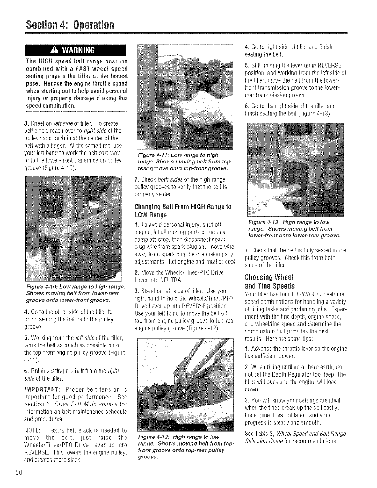
Figure 4=9: Belt range positions.
Whenthe tiller is moving in REVERSE,the
wheels are powered by a rubberreverse
disc, not by the belt. Therefore, you have
onlytwo reversespeedsSLOWand FAST,
as set with the WheelSpeedLever.
Table4-1 shows the range of wheeiand
tine speeds availablewhen usingthe two
bdt speed rangesand the FASTand
SLOWselections onthe WheelSpeed
Lever.
Table 4-1
Available wheel and tine speeds at 3888 RP_
engine speed.
Wheel
Belt Speed Wheel Tine
Position Lever Speed Speed
Low Range Slow ,5MPH 146RPM
Low Range Fast 12MPH 146RPM
High Range Slow ,7MPH 200RPM
High Range Fast 1,72MPH 200RPM
Changing Belt From LOW Range
in HIGH Range
1. To avoid personalinjury, shut off
engine, iet alimoving partscometo a
compiete stop, then disconnect spark
piug wire from spark piug and move it
away from spark piug before making any
adjustments. Wait for the engineand
muffler to cooIdown.
2. Move Wheels,rrines/PTODrive Lever
into NEUTRAL.
19
Section4: Operation
The HiGH speed belt range position
combined with a FAST wheel speed
setting propels the tiller at the fastest
pace. Reduce the enginethrottle speed
when starting outto help avoid personal
injury or propertydamage if using this
speed combination.
3. Kneelon fefiside of tiller. To create
beit slack, reachoverto right side ofthe
pulieys and push in atthe center of the
beit with a finger. At the sametime, use
your ieft hand to work the belt part=way
onto the iower=fronttransmission pulley
groove (Figure 4=10).
4. Goto right sideof tiller and finish
seatingthe beit.
5. Stiil holding the iever up in REVERSE
position, and working from the ieft side of
thetiiier, move the beit from the lower=
front transmission grooveto the lower-
reartransmission groove.
6. Goto the right side of the tiiier and
finish seatingthe belt (Figure4-13).
Figure 4-11: Low range to high
range. Shows moving belt from top=
rear groove onto top-front groove.
7. Checkboth sides of the high range
puiiey grooves to verify that the belt is
properly seated.
Changing Belt Frem HiGH Range te
LOW Range
1. To avoid personal injury,shut off
engine,iet aii movingparts cometo a
complete stop, then disconnect spark
plug wire from spark piug and movewire
away from sparkpiug before making any
adjustments. Letengineand muffler cool.
2. Move the Wheels/Tines/PTODrive
Leverinto NEUTRAL.
Figure 4o10: Low range to high range.
Shows moving belt from lower-rear
groove onto IowerWront groove.
3. Standon Ieftside of tiiier. Useyour
right handto holdthe Wheels/Tines/PTO
Drive Leverupinto REVERSEposition.
4. Goto the other side ofthe tilier to Useyour ieft handto movethe belt off
finish seatingthe belt onto the putley top-front enginepuiiey groovetotop-rear
groove, engine pulleygroove (Figure4-12).
5. Working from the left sideof the tiller, _ ::::
work the bett as muchaspossibie onto
thetop-front enginepulley groove (Figure
4-11).
6. Finish seatingthe beltfrom the right
sideof thetiller.
JNIPORTANT: Proper beittension is
important for good performance. See
Section 5, Drive Belt Maintenance for
information on belt maintenance schedule
and procedures.
NOTE: If extra belt slack is needed to
move the belt, just raise the
Wheels/Tines/PTO Drive Lever up into
REVERSE.This iowers the engine puiley,
and createsmore slack.
Figure 4-12: High range to low
range. Shows moving belt from top-
front groove onto top-rear pulley
groove.
Figure 4-13: High range to low
range. Shows moving belt from
Iowet=front onto Io wet-rear groo re.
7. Checkthat the bett is fully seatedin the
pulley grooves. Checkthis from both
sides of the tiiier.
Choosing Wheel
and TineSpeeds
Your tilier hasfour FORWARDwheei/tine
speedcombinationsfor handling avariety
of tiiiing tasksandgardeningjobs. Exper-
iment withthe fine depth, enginespeed,
and wheel/finespeedand determine the
combination that provides the best
results. Hereare some tips:
1. Advancethe throttle leverso the engine
hassufficient power.
2. Whentiffing untiiied or hard earth, do
not set the DepthRegulatortoo deep.The
tiiier will buckandthe engine will load
down.
3. You will know your settings areideal
whenthe tines break-upthe soil easily,
the enginedoes not iabor, andyour
progress is steadyandsmooth.
SeeTable2, Wbee/Speedand BettRange
Se/ectionGuidefor recommendations.
2O
 Loading...