


INSTRUCTION BOOK
Part No. 501528
TRIUMPH
SPORTS CAR
TR3
SIXTH EDITION
Third Printing
Issued by
STANDARD-TRIUMPH SALES LIMITED
COVENTRY, ENGLAND

Fig. 1. 'THE TRIUMPH TR3 SPORTS CAR
FOREWORD
Triumph vehicles are so designed that a minimum of attention is required to keep them in satisfactory running order. There are, however, certain maintenance operations which must be undertaken regularly. The object of this instruction book is to assist the owner to understand the various operations required, and so ensure that the vehicle receives regular and correct attention.
If in doubt about the vehicle's performance the owner should at once consult a Triumph dealer, preferably the one from whom the car was purchased. Triumph dealers are very carefully selected and are suitably equipped to give
satisfactory and expert after-sales service .
There is a Training organisation at the factory at which our dealers' representatives acquire a first hand knowledge of up-to-date service procedure. Valuable information is given regarding special technique and equipment which ensures that all maintenance operations are carried out economically.
THE STANDARD-TRIUMPH REVIEW
The Standard-Triumph Review is a journal published monthly which gives authentic information regarding the activities and products of The Standard & Triumph Motor Co. Ltd. It is obtainable from most Triumph dealers. Please write to the Publicity Department for a free specimen copy.
The Company reserves the right, on the sale of any vehicle, to make before delivery, without notice, alterations to or departures from the specification, design or equipment, detailed, described or illustrated in this or other Company publications.
IMPORTANT—In all communications relating to Service or Spares please quote the Commission Number (Chassis Number).
LOCATION OF COMMISSION AND UNIT NUMBERS
Commission Number—On Scuttle Panel. (May be seen by lifting the bonnet.)
Engine Number—On L.H. side of Cylinder Block.
Gearbox Number—On L.H. side of housing.
Rear Axle Number—On upper face of Hypoid Housing Flange.
SPARE PARTS SERVICE
To ensure the best possible service on replacement parts it is important to note the following points :
(a)Spare parts are not supplied direct to the general public. All supplies are directed through Distributors who, in turn, will supply their Dealers. The name and address of the Distributors and Dealers may be obtained from the Service and Spares Directory included with each motor vehicle.
(b)It is recommended that only " Stanparts " (i.e., genuine Standard/ Triumph spare parts) are used, only these carry a guarantee. Experience gained by the manufacturers ensures that only highest quality material is used and the strictest accuracy maintained in manufacture.
(c)If in doubt about a particular part required, it is always advisable to give the vehicle commission number and engine number, in addition to the fullest description possible.
Owners of this model who wish to be kept informed of modifications and competition tuning hints should register as a member of the Triumph Sports Owners' Association ; details are given in the booklet enclosed with this literature, or apply to the Publicity Dept., Standard-Triumph Sales Limited, Coventry, England, for a copy of the book, together with enrolment form.
4
LIST OF SECTIONS
Foreword |
3 |
General Specification |
6 |
Instruments, Switches and Controls |
8 |
Driving the Car |
11 |
Starting—Gear Changing—Desirable Speed Limits—New Engines |
|
General Upkeep |
13 |
Regular Inspection — Cooling System — Lubrication — Engine |
|
—Gearbox—Rear Axle—Brake and Clutch Operation—Road |
|
Wheel Hubs—Front Suspension and Steering—Rear Road Springs |
|
—Hydraulic Dampers—Propeller Shaft—Hinges, |
Controls, |
Door Locks, etc.—Tyres—Front Wheel Alignment—The Jack |
|
—Wheel Attachment |
|
Tools |
26 |
Bodywork |
27 |
Door Adjustment—Soft Top Maintenance—Removal and Stowage |
|
of Soft Top |
|
Running Adjustments |
31 |
Engine—Twin S.U. Carburettors (Type H.6)—Fuel Pump— |
|
Clutch—Brakes—Propeller Shaft—Hydraulic Dampers—Loose |
|
Bolts and Nuts |
|
Electrical System ... |
42 |
Ignition—The Battery—The Generator—The Starter Motor— |
|
Control Box — Fuses — Lamps — Wiring Diagram — |
|
Direction Indicators—Windtone Horns—Electrical |
Component |
Specification |
|
Optional Extras |
51 |
Lubrication Charts |
52 |
Summary of Lubrication Points |
54 |
5 |
SPORTS CAR |
GENERAL SPECIFICATION
Engine |
|
|
|
|
|
|
Number of cylinders |
|
|
|
|
|
4 |
Bore of cylinders |
|
|
|
|
3.386 in. (86 mm.) |
|
(Special Order) ... |
|
|
|
|
3.268 in. (83 mm.) |
|
Stroke of crankshaft |
|
|
|
|
3.622 in. (92 mm.) |
|
Piston area ... |
|
|
|
36 sq. in. (232 sq. cm.) |
||
(Special Order) |
|
|
|
33.5 sq. in. (216 sq. cm.) |
||
Cubic capacity |
|
|
|
130.5 cu. in. |
(2138 c.c.) |
|
(Special Order) ... |
|
|
|
121.5 cu. in. |
(1991 c.c.) |
|
Compression ratio ... |
|
|
|
|
|
9 or 7 |
Brake H.P. (gross) ... |
|
|
|
|
105 at 4750 r.p.m. |
|
(Special Order) ... |
|
|
|
|
100 at 5000 r.p.m. |
|
Oil Capacity |
|
|
|
Imperial U.S. |
|
|
|
|
|
Pints |
Pints |
|
|
Engine |
From Dry |
(see page 14) |
11 |
13.2 |
(6.25 litres) |
|
|
Drain and Refill ... |
... |
10 |
12 |
(5.7 litres) |
|
Gearbox |
|
|
|
1½ |
1.8 |
(0.8 litres) |
with overdrive—From dry ... |
... |
3½ |
4.2 |
(2.0 litres) |
||
|
Drain and Refill ... |
2¾ |
3.3 |
(1.6 litres) |
||
Rear Axle |
|
|
|
1½ |
1.8 |
(0.8 litres) |
Water Capacity of cooling system |
... |
... |
13 |
15.7 |
(7.4 litres) |
|
with heater fitted |
... |
... |
14 |
16.8 |
(8.0 litres) |
|
Fuel Capacity |
|
|
|
Gallons |
(54.5 litres) |
|
|
|
|
12 |
14.4 |
||
Dimensions: |
|
|
|
|
|
(224 cm.) |
Wheelbase |
|
|
|
7' |
4" |
|
Track—Front and Rear (Disc Wheels) |
... |
3' |
9" |
(114 cm.) |
||
Front and Rear (Wire Wheels) |
... |
3' |
10" |
(117 cm.) |
||
Ground clearance (under axle) |
... |
... |
|
6" |
(15.2 cm.) |
|
Turning circle (between kerbs) |
... |
... |
35' |
0' |
(10.6 metres) |
|
Tyre size |
|
|
|
|
5.50"/5.90"—15 |
|
Overall Dimensions: |
|
|
|
|
|
(384 cm.) |
Length |
|
|
|
12' |
7" |
|
Width ... |
|
|
|
4' |
7½" |
(141 cm.) |
Height (unladen)—Hood erect |
... |
... |
4' |
2" |
(127 cm.) |
|
|
Top of screen ... |
... |
3' |
10" |
(117 cm.) |
|
|
Hood down and screen |
|
|
|
||
|
removed ... |
... |
3' |
4' |
(102 cm.) |
|
Weights (excluding extra equipment) |
|
|
|
|
||
Complete, tank full of petrol |
|
|
|
19 cwts. 0 qrs. 7 lbs. |
||
|
|
|
|
|
(2135 lb.) (970 kg.) |
|
Shipping weight |
|
|
|
|
17 cwts. 3 qrs. 21 lbs. |
|
|
|
|
|
|
(2009 lb.) (910 kg.) |
|
6
GENERAL SPECIFICATION
VALVE TIMING. [With valve-rocker clearance set at 0.0165" (0.42 mm.)].
Inlet and exhaust valves to be equally open at T.D.C. on the exhaust stroke.
VALVE-ROCKER CLEARANCES (see page 31).
IGNITION TIMING (see page 31).
Set to fire at 4° before top dead centre (distributor contact points just opening). As the advance is fully automatic, the setting is at full retard.
Contact breaker gap should be set at 0.015" (0.4 mm.).
ROAD SPEED DATA
|
|
|
O.D. |
|
|
Top |
O.D. |
3rd |
O.D. |
2nd |
1st |
Rev. |
|
|
|
|
Top |
|
|
3rd |
2nd |
|
|||||
Engine Speeds (3.7 axle) |
|
|
|
|
|
|
|
|
|
|
|
||
|
|
|
|
|
|
|
|
|
|
|
|||
Using |
Dunlop Textile |
|
|
|
|
|
|
|
|
|
|
|
|
Tyres: |
|
|
412 |
|
501 |
545 |
664 |
825 |
1007 |
1573 |
1615 |
|
|
at 10 m.p.h. |
|
|
|
||||||||||
at 10 km./hr. |
|
250 |
|
310 |
340 |
410 |
510 |
620 |
970 |
1005 |
|
||
Using Michelin X Tyres: |
|
|
|
|
|
|
|
|
|
|
|
||
409 |
|
498 |
541 |
660 |
820 |
1001 |
1563 |
1605 |
|
||||
at 10 m.p.h. |
... |
|
|
||||||||||
at 10 km./hr. |
254 |
|
309 |
336 |
410 |
509 |
622 |
971 |
997 |
|
|||
|
|
|
|
|
|
|
|
|
|
|
|
||
Engine Speeds (4.1 axle) |
|
|
|
|
|
|
|
|
|
|
|
||
Using |
Dunlop Textile |
|
|
|
|
|
|
|
|
|
|
|
|
Tyres: |
|
|
455 |
|
556 |
604 |
736 |
916 |
1170 |
1744 |
1790 |
|
|
at 10 m.p.h. |
... |
|
|
||||||||||
at 10 km./hr. |
283 |
|
345 |
375 |
467 |
579 |
694 |
1083 |
1112 |
|
|||
Using Michelin X Tyres: |
|
|
|
|
|
|
|
|
|
|
|
||
452 |
|
552 |
601 |
731 |
910 |
1110 |
1733 |
1779 |
|
||||
at 10 m.p.h. |
... |
|
|
||||||||||
at 10 km /hr. |
|
281 |
|
343 |
373 |
454 |
565 |
691 |
1077 |
1105 |
|
||
|
|
|
|
|
|
|
|
|
|
|
|
|
|
|
|
|
|
GEAR RATIOS |
|
|
|
|
|
||||
|
|
|
|
|
|
|
|
|
|
|
|
||
|
|
|
O.D. |
Top |
O.D, |
3rd |
O.D. |
2nd |
1st |
Rev. |
|
||
|
|
|
Top |
|
|
3rd |
2nd |
|
|||||
|
|
|
|
|
|
|
|
|
|
|
|
||
Gearbox Ratios |
... |
0.82 |
|
|
1 |
1.09 |
1.325 |
1.65 |
2.01 |
3.139 |
3.223 |
|
|
|
|
|
|
|
|
|
|
|
|
|
|
|
|
3.7 : 1 Axle |
... |
3.034 |
|
|
3.7 |
4.02 |
4.9 |
6.1 |
7.44 |
11.61 |
11.93 |
|
|
Overall Ratios |
|
|
|||||||||||
|
|
|
|
|
|
|
|
|
|
|
|
|
|
4.1:1 |
Axle |
... |
3.36 |
|
|
4.17 |
4.46 |
5.44 |
6.76 |
8.24 |
12.87 |
13.21 |
|
Overall Ratios |
|
|
|||||||||||
|
|
|
|
|
|
|
|
|
|
|
|
|
|
7 |
SPORTS CAR |
INSTRUMENTS, SWITCHES AND CONTROLS
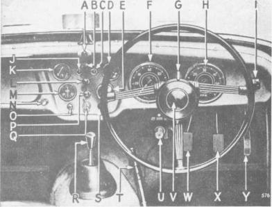
Fig. 2. Instruments, switches and controls.
NOTE :—In left-hand drive cars D changes with K, E with M, and F with H.
AScuttle Ventilator Control. To open ventilator pull control knob.
BWindscreen Wiper Switch. Pull knob to operate ; they will only function when the ignition is switched on. They will return automatically to the parked position when switched off.
CDirection Indicator Warning Light. Will flash when the switch G is operated and the ignition is switched on.
DOil Pressure Gauge. Indicates pressure of oil at the bearings. The gauge should read 70 lb./sq. in. minimum when the car is travelling at normal speeds and the oil is hot.
Low pressure may be registered when the engine is idling or running at low speeds ; this is quite normal.
EWater Temperature Gauge. The gauge shows the temperature of the cooling water at the thermostat. Under normal motoring conditions the water temperature should not exceed 185°F.
FSpeedometer. Registers vehicle's speed and total distance covered, and is fitted with a trip which is cancelled by pushing up the serrated knob (situated under the instrument) and turning anti-clockwise.
GDirection Indicator Switch. These self-cancelling indicators will only operate with the ignition switched on, and a warning light (C) will flash on the dash panel when the switch is operated.
8
INSTRUMENTS, SWITCHES AND CONTROLS
HTachometer. Indicates the engine speed in revolutions per minute. (See page 12).
IOverdrive Control Switch. See page 51.
JIgnition Warning Light. Glows red when the ignition is switched on with the engine idling or stopped. It is an indication that current is being drawn from the battery for the ignition circuit, or other purposes that are controlled by the ignition switch.
KFuel Contents Gauge. Registers the approximate amount of fuel in the tank. It operates automatically when the ignition is switched on.
L |
Instrument Panel Light Switch. Turn knob clockwise to switch |
|
on panel lights, further clockwise movement will progressively dim |
|
the illumination. |
|
These lights will only operate when the parking lights are switched on. |
M |
Ammeter. Indicates the flow of current into or out of the battery. |
NScreen Wash Control (where fitted). To operate push the control knob.
OStarter Switch. Press to operate engine starter (see page 11 for full instructions).
PHead, Tail and Parking Lamp Switch. Pull knob to switch on parking lights. Turn slightly clockwise and pull again to switch on the head lights. Press foot operated switch (U) to dip head lights, press again for " full on " position, in which position a small red light appears at the bottom of the speedometer dial.
QIgnition Switch. Insert key and turn clockwise to switch on. Do not leave the switch " on " when engine is stationary.
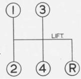
RGear Change Lever. See Fig. 3 for gear positions.
SChoke Control. See page 11 for full instructions.
THandbrake. Pull to operate rear wheel brakes, the handbrake lever can be retained in any position by pressing the button on the top of the lever. To release the handbrake lever, first pull it, this will cause the pawl to be automatically disengaged from the ratchet, the lever is then free to move forwards and release the brakes.
UHeadlamp Dipper Switch. Press foot operated switch to dip headlamps; press again for high beam position. A small red indicator light in the speedometer glows when the headlamps are operating in this position.
VHorn Button. Press button in centre of steering wheel to operate horns.
Fig. 3. Gear lever positions.
9 |
SPORTS CAR |
INSTRUMENTS, SWITCHES AND CONTROLS
WClutch Pedal. Press pedal to disengage drive from engine to gearbox. Do not rest your foot on the pedal when driving, or hold clutch out to free wheel.
XBrake Pedal. Press to operate all wheel brakes hydraulically.
YAccelerator Pedal. Press to accelerate the vehicle.
See page 51.
The seats are adjustable for " leg length " after operating the lever which is situated at the side of the seat.
See page 51.
The fasteners at each side of the bonnet can be released by turning them anti-clockwise with the special key provided. The safety catch is situated under the front of the bonnet, in line with the " H " of TRIUMPH and may be released with the fingers. (Fig. 4).
846
Fig. 4. Releasing bonnet safety catch.
1 0
DRIVING THE CAR
TO START THE ENGINE
IMPORTANT
If the engine does not start when the starter is first operated, do not operate the starter again until both starter motor and engine have come to rest. This will avoid damage to the starter pinion.
Starting when Engine is Cold
Place the gear lever in the neutral position and apply the handbrake. Pull the carburettor choke control out to its stop, switch on the ignition and press the starter switch button. When the engine has warmed up, turn the choke control and allow it to return to the half-out position and turn to lock in this position. When the engine is sufficiently hot to run without undue hesitation, push the control fully home. If the battery is low use the starting handle. Should difficulty be experienced when starting the engine, do not keep the choke control out for too long or the sparking plugs will become wet with petrol. This will necessitate removing and drying them. When the car has been left standing for some time, the fuel in the carburettor float chambers may have evaporated. Under such circumstances, operate the hand primer on the fuel pump before the starter is operated. (See page 37).
When operating the starter in very cold conditions, depress the clutch pedal to relieve the motor of the considerable drag in the gearbox.
Starting with Engine Warm or Hot
When restarting a hot engine, depress the accelerator pedal to about onethird of its travel before pressing the starter button, the choke control should not be used.
Warming up
In order to minimise cylinder wear when starting from cold in winter, the engine should be warmed up quickly. Idle the engine until the oil circulates and then speed it up. It should not be allowed to idle for long periods and must not be raced up to high speeds when cold. An engine speed of approximately 1,500 r.p.m. may be regarded as a desirable warming up speed.
1 1 |
SPORTS CAR |
DRIVING THE CAR
DRIVING
Gear Changing
Use a slow and deliberate movement to change gear, and always move the gear lever fully home. Do not engage first gear at speeds in excess of 15 m.p.h. Reverse gear must not be engaged whilst the car is moving forward.
Desirable Speed Limits (Particularly in gears lower than top)
Avoid over-revving, particularly in the lower gears. The driver is advised not to drive the car continuously at engine speeds above 4,500 r.p.m. in any gear. However, whilst accelerating through the gears it is permissible to attain 5,000 r.p.m. for short periods. this speed being indicated by a red mark on the tachometer.
New Engines (see "Running Adjustments ")
For at least the first 500 miles, the working surfaces of the engine will be bedding down. The power and performance will improve only if the vehicle is carefully driven at moderate speeds during the running-in period.
The engine should not be driven at speeds exceeding 3,500 r.p.m. during this period, and the " running-in " should be progressive. The engine may " rev." fairly fast so long as it is thoroughly warm and provided it is not pulling hard. Do not let the engine pull hard at low speeds, always select a lower gear.
12
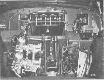
subsequently attack the surrounding metal panels.
water when replenishing. Keep the filler plugs (A) (Fig. 5) screwed tight to prevent leakage. Never use a naked light when checking the electrolyte level.
Fig. 5. View under bonnet.
13 |
SPORTS CAR |
GENERAL UPKEEP
COOLING SYSTEM
Filling (see page 13).
Draining
Taps are provided in the bottom tank of the radiator and at the rear of the cylinder block on the right-hand side. As the cooling system is pressurised it will be necessary, when draining, to remove the radiator cap (E) (Fig. 5).
If a heater is fined, ensure that the tap (C) (Fig. 5) is open before draining.
Anti-Freeze Mixtures
Protect the cooling system during frosty weather and reduce corrosion to a minimum, by use of an inhibited anti-freeze. The use of Smith's "Bluecol", Duckham's Anti-freeze, Esso Anti-freeze, Castrol Anti-freeze, Shell " Snowflake " or Mobil Permazone Anti-freeze (inhibited Glycol base compound) is recommended. The cooling system is fitted with a thermostat and there is a risk of the radiator block freezing while the engine is running during the warming up period when the thermostat is shut, even though the car has been left in a warm garage and water is not frozen at the start of the run.
Provide ample protection for the cooling system against a sudden fall in temperature down to 0°F. (-18°C.) during frosty weather by using 3 pints (Imperial) of anti-freeze.
In countries where sub-zero temperatures prevail, consult your Triumph dealer regarding the quantity of anti-freeze required.
Do not use the same anti-freeze for more than one season since the inhibitor becomes exhausted and the components in contact with the cooling water may corrode.
LUBRICATION
This is one of the most important subjects in connection with the upkeep of a car, and careful attention to the following instructions will be amply repaid by the results obtained.
For the recommended periods of lubrication, see the lubrication chart (page 54). The correct lubricants to be used are given on pages 52 and 53 .
14
GENERAL UPKEEP
Draining
To drain the engine, gearbox and rear axle, remove the plug provided beneath each unit. This process is assisted by opening the filler to allow ingress of air and by draining when the oil is hot, i.e., immediately after a run.
ENGINE
Only first quality oils are recommended for use in the engine sump. These are of correct viscosity and character to afford complete lubrication protection for normal driving. Additives which dilute the oil or otherwise impair this
not be used.
Engine Oil Drain Period
The frequency of the drain period should be related to the driving conditions to which the vehicle is subjected. 3,000 mile intervals are recommended for average driving conditions as defined below. This should be reduced for unfavourable conditions and may be extended for those more favourable.
Favourable
Long distance journeys, with little or no engine idling, on well surfaced roads, reasonably free from dust.
Average
Medium length journeys on well surfaced roads with a small proportion of stop/start operation.
Unfavourable
Any of the following:
(a)Frequent stop/start driving.
(b)Operation during cold weather, especially when appreciable engine idling is involved.
(c)Where much driving is done under dusty conditions.
An upper cylinder lubricant may be used to advantage, during the runningin period of a new engine. The lubricant should be mixed with the fuel in the proportions given on the container. Such lubricants may be used with advantage throughout the life of the vehicle, particularly during wintry weather.
15 |
SPORTS CAR |
GENERAL UPKEEP
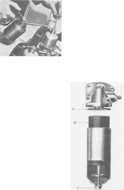
Every 3,000 miles remove the dampers (indicated by arrows) and replenish the dashpots with oil. The oil level is correct when, utilizing the damper as a dipstick its threaded plug is approximately ¼" above the dashpots, when resistance is felt. Apply oil to the throttl e linkage but do not oil the bearings of the transverse rod attached to the bulkhead as this will seriously deteriorate the sealing compound.
Fig. 6. Replenishing dashpots.
The Oil Filter
The oil filter is designed to filter the oil to a very fine degree. It will continue to do this provided that the old cartridge (B) is removed and a new replacement cartridge is fitted at periods not exceeding 6,000 miles. Should this operation be neglected, the cartridge will become choked and unfiltered oil will then be passed to the engine via the balance valve in the filter. To renew the cartridge, unscrew the securing bolt (C), remove the container and withdraw the cartridge.
Wash out the container to remove foreign matter trapped by the filter, and discard the old container washer (A), replacing it with a new one each time the cartridge is renewed. When reassembling the container, ensure that the washer is correctly positioned in the groove in the filter body. Do not tighten the bolt (C) more than is necessary to obtain an oil-tight joint. Drain the engine oil and refill with fresh oil before re-starting the engine.
Fig. 7. Oil Filter " full-flow " type.
1 6
 Loading...