


Triumph Rocket Ill, Rocket III Classic and
Rocket III Touring
Motorcycle Service Manual
(
\
Part Number 3851160 issue 1,09.2007
This document is protected by copyright and may not, in whole or part be stored in a retrieval system, or transmitted in any form or by any means, copied, photocopied, translated or reduced to any machine-readable form without prior consent in writing from Triumph Motorcycles Limited.
No liability can be accepted for any inaccuracies or omissions in this publication, although every possible care has been taken to make it as complete and accurate as possible.
Triumph Motorcycles Limited reserves the right to make changes and alter specifications without prior notice and without incurring an obligation to make such changes to products manufactured previously. See your authorised Triumph dealer for the latest information on product improvements incorporated after this publication.
All information contained in this publication is based on the latest product information available at the time of publication. Illustrations in this publication are intended for reference use only and may not depict actual model component parts.
© Triumph Motorcycles Ltd 2007
SelVice ManualRocket Ill/ Classic / Touring |
1 |

2 |
SelVice Manual - Rocket 1111 Classic 1 Touring |

Table of Contents
Introduction
General Information
Scheduled Maintenance
Cylinder Head
Clutch
Crankshaft
Bevel Box and Drive Shaft
Balancer
Transmission
Lubrication
Engine Removal and Refit
Fuel System/Engine Management
Cooling
Rear Suspension
Front Suspension
Brakes
WheelslTyres
Frame and Bodywork
Electrical System
Service ManualRocket Ill/ Classic / Touring

ii |
SelVice Manual - Rocket Ill/ Classic / Touring |

Introduction
SelVice Manual - Rocket Ill/ Classic / Touring |
iii |
Introduction
This manual is designed primarily for use by trained technicians in a properly equipped workshop. However, it contains enough detail and basic information to make it useful to the owner who desires to perform his own basic maintenance and repair work. The work can only be carried out if the owner has the necessary hand and special service tools to complete the job.
A basic knowledge of mechanics, including the proper use of tools and workshop procedures is necessary in order to carry out maintenance and repair work satisfactorily. Whenever the owner has insufficient experience or doubts his ability to do the work, an authorised Triumph dealer must undertake all adjustments, maintenance, and repair work.
In order to perform the work efficiently and to avoid costly mistakes, read the text and thoroughly familiarise yourself with procedures before starting work.
All work should be performed with great care and in a clean working area with adequate lighting.
Always use the correct special service tools or equipment specified. Under no circumstances use makeshift tools or equipment since the use of substitutes may adversely affect safe operation.
Where accurate measurements are required, they can only be made using calibrated, precision instruments.
For the duration of the warranty period, an authorised Triumph dealer must perform all repairs and scheduled maintenance.
To maximise the life of your Motorcycle:
Accurately follow the maintenance requirements of the periodic maintenance chart in the service manual.
Do not allow problems to develop. Investigate unusual noises and changes in the riding characteristics of the motorcycle. Rectify all problems as soon as possible (immediately if safety related).
Use only genuine Triumph parts as listed in the parts catalogue/parts microfiche.
Follow the procedures in this manual carefully and completely. Do not take short cuts.
Keep complete records of all maintenance and repairs with dates and any new parts installed.
Use only approved lubricants, as specified in the owner's handbook, in the maintenance of the motorcycle.
How to use this manual
To assist in the use of this manual, the section title is given at the top.
Each major section starts with a contents page, listing the information contained in the section.
The individual steps comprising repair operations are to be followed in the sequence in which they appear.
Adjustment and repair operations include reference to service tool numbers and the associated illustration depicts the tool.
Where usage is not obvious, the tool is shown in use.
Adjustment and repair operations also include reference to wear limits, relevant data, torque figures, specialist information and useful assembly details.
Warnings, Cautions and Notes
Particularly important information is presented in the following form:
warning symbol identifies special instructions or procedures which, if not correctly followed, could result in personal injury, or loss of life.
This caution symbol identifies special instructions or procedures which, if not strictly observed, could result in damage to or destruction of equipment.
Note:
•This note symbol indicates points of particular interest for more efficient and convenient operation.
iv |
SelVice Manual - Rocket III I Classic I Touring |

Introduction
Tampering with Noise Control System Prohibited
Owners are warned that the law may prohibit:
a)The removal or rendering inoperative by any person other than for purposes of maintenance, repair or replacement, of any device or element of design incorporated into any new vehicle for the purpose of noise control prior to its sale or delivery to the ultimate purchaser or while it is in use; and
b)the use of the vehicle after such device or element of design has been removed or rendered inoperative by any person.
References
References to the left hand or right hand side given in this manual are made when viewing the motorcycle from the rear.
Operations covered in this manual do not always include reference to testing the motorcycle after repair. It is essential that work is inspected and tested after completion and if necessary a road test of the motorcycle is carried out particularly where safety related items are concerned.
Dimensions
The dimensions quoted are to design engineering specification with service limits where applicable.
During the period of running-in from new, certain adjustments may vary from the specification figures given in this manual. These will be reset by the dealer at the 500 mile/800 km service, and thereafter should be maintained at the figures specified in this manual.
Repairs and Replacements
Before removal and disassembly, thoroughly clean the motorcycle. Any dirt entering the engine or other parts will work as an abrasive and shorten the life of the motorcycle. Particular attention should be paid when installing a new part, that any dust or metal filings are cleared from the immediate area.
Force
Common sense should dictate how much force is necessary in assembly and disassembly. If a part seems especially difficult to remove or install, stop and examine what may be causing the problem. Never lever a component as this will cause damage both to the component itself and to the surface being levered against.
Whenever tapping to aid removal of an item is necessary, tap lightly using a hide or plastic faced mallet.
Edges
Watch for sharp edges, especially during engine disassembly and assembly. Protect the hands with industrial quality gloves.
When replacement parts are required, it is essential that only genuine Triumph parts are used.
Safety features and corrosion prevention treatments embodied in the motorcycle may be impaired if other than genuine Triumph parts are fitted. In certain territories, legislation prohibits the fitting of parts not to the manufacturer's specification.
Tightening procedure
Generally, when installing a part with several bolts, nuts or screws, they should all be started in their holes and tightened to a snug fit, evenly and in a cross pattern. This is to avoid distortion of the part and/or causing gas or oil leakage. Conversely, bolts, nuts, or screws, should all be loosened (in sequence if specified) by about a quarter of a turn and then removed.
Where there is a tightening sequence specified in this Service Manual, the bolts, nuts, or screws must be tightened in the order and by the method indicated.
Torque wrench setting figures given in this Manual must be observed. The torque tools used must be of accurate calibration.
Locking devices, where specified, must be fitted. If the efficiency of a locking device is impaired during removal it must be renewed. This applies particularly to microencapsulated fixings which must always be replaced if disturbed. Where necessary, the text in this manual will indicate where such a fixing is used.
Service Manual - Rocket Ill/ Classic / Touring |
v |

Introduction
This page intentionally left blank
vi |
SelVice Manual - Rocket Ill/ Classic |

1 General Information |
||
Table of Contents |
|
|
Ignition System Safety Precautions. . . . . . . . . . . . . . . . . . . . . . . . . . . . . . . . . . . . . . . . . . . . . . . . . . . . . . . . . . . |
1.4 |
|
Dangerous Substances. . . . . . . . . . . . . . . . . . . . . . . . . . . . . . . . . . . . . . . . . . . . . . . . . . . . . . . . . . . . . . . . . . . . . |
1.4 |
|
Third Party Products. . . . . . . . . . . . . . . . . . . . . . . . . . . . . . . . . . . . . . . . . . . . . . . . . . . . . . . . . . . . . . . . . . . . . . . |
1.4 |
|
Fluoroelastomers. . . . . . . . . . . . . . . . . . . . . . . . . . . . . . . . . . . . . . . . . . . . . . . . . . . . . . . . . . . . . . . . . . . . . . . . . . |
1.4 |
|
Oils........................ ... ........ ....................... ... ...... ......... ...... ... |
1.4 |
|
Health Protection Precautions. . . . . . . . . . . . . . . . . . . . . . . . . . . . . . . . . . . . . . . . . . . . . . . . . . . . . . . . . . . . . . . |
1.4 |
|
Environmental Protection Precautions . . . . . . . . . . . . . . . . . . . . . . . . . . . . . . . . . . . . . . . . . . . . . . . . . . . . . . . . |
1.5 |
|
Brakes. . .. . . . . .. . . . ... . . . .. . .. . .. . .. .. . .. . . . . . . . .. . . . .. . . . . .. . .. . .. . . .. . .. . .. . . . ... ... .. . |
1.5 |
|
Safety Instructions. . . . . . . . . . . . . . . . . . . . . . . . . . . . . . . . . . . . . . . . . . . . . . . . . . . . . . . . . . . . . . . . . . . . . . . . . |
1.6 |
|
Jacking and Lifting. . . . . . . . . . . . . . . . . . . . . . . . . . . . . . . . . . . . . . . . . . . . . . . . . . . . . . . . . . . . . . . . . . .. |
1.6 |
|
Precautions against Damage . . . . . . . . . . . . . . . . . . . . . . . . . . . . . . . . . . . . . . . . . . . . . . . . . . . . . . . . . .. |
1.6 |
|
Coolant. . . . . . . . . . . . . . . . . . . . . . . . . . . . . . . . . . . . . . . . . . . . . . . . . . . . . . . . . . . . . . . . . . . . . . . . . . . .. |
1.7 |
|
Cleaning components.. . . . . . . . . . . . . . . . . .. . .. . . . . .. . .. . .. . . . . . . . . . . .. . . . . . . .. . . . . . . . . .. |
1.7 |
|
Lubrication. . . . . . . . . . . . . . . . . . . . . . . . . . . . . . . . . . . . . . . . . . . . . . . . . . . . . . . . . . . . . . . . . . . . . . . . .. |
1.7 |
|
Joints and joint faces. . . . . . . . . . . . . . . . . . . . . . . . . . . . . . . . . . . . . . . . . . . . . . . . . . . . . . . . . . . . . . . . .. |
1.7 |
|
Gaskets, O-rings. . . . . . . . . . . . . . . . . . . . . . . . . . . . . . . . . . . . . . . . . . . . . . . . . . . . . . . . . . . . . . . . . . . . .. |
1.7 |
|
Liquid Gasket, Non-permanent Locking Agent. . . . . . . . . . . . . . . . . . . . . . . . . . . . . . . . . . . . . . . . . . .. |
1.8 |
|
Screw Threads . . . . . . . . . . . . . . . . . . . . . . . . . . . . . . . . . . . . . . . . . . . . . . . . . . . . . . . . . . . . . . . . . . . . . .. |
1.8 |
|
Locking Devices. . . . . . . . . . . . . . . . . . . . . . . . . . . . . . . . . . . . . . . . . . . . . . . . . . . . . . . . . . . . . . . . . . . . .. |
1.8 |
|
Fitting a Split Pin . . . . . . . . . . . . . . . . . . . . . . . . . . . . . . . . . . . . . . . . . . . . . . . . . . . . . . . . . . . . . . . . . . . .. |
1.8 |
|
Circlips, Retaining Rings. . . . . . . . . . . . . . . . . . . . . . . . . . . . . . . . . . . . . . . . . . . . . . . . . . . . . . . . . . . . . .. |
1.8 |
|
Self Locking Nuts. . . . . . . . . . . . . . . . . . . . . . . . . . . . . . . . . . . . . . . . . . . . . . . . . . . . . . . . . . . . . . . . . . . .. |
1.8 |
|
Encapsulated Bolts. . . . . . . . . . . . . . . . . . . . . . . . . . . . . . . . . . . . . . . . . . . . . . . . . . . . . . . . . . . . . . . . . . .. |
1.8 |
|
Oil and Grease Seals. . . . . . . . . . . . . . . . . . . . . . . . . . . . . . . . . . . . . . . . . . . . . . . . . . . . . . . . . . . . . . . . .. |
1.9 |
|
Press. . . . . . . .. . . . . . . . . . . . . . . . . . . . . . . .. . .. . .. . . . .. . . . . . . . . . . . . . . . . .. . . . . .. . .. . .. . .. .. |
1.9 |
|
Ball Bearing. . . . . . . . . . . . . . . . . . . . . . . . . . . . . . . . . . . . . . . . . . . . . . . . . . . . . . . . . . . . . . . . . . . . . . . . .. |
1.9 |
|
Chassis Bearing Lubrication. . . . . . . . . . . . . . . . . . . . . . . . . . . . . . . . . . . . . . . . . . . . . . . . . . . . . . . . . . .. |
1.9 |
|
Metal bushes . . . . . . . . . . . . . . . . . . . . . . . . . . . . . . . . . . . . . . . . . . . . . . . . . . . . . . . . . . . . . . . . . . . . . .. |
1.10 |
|
Fuel Handling Precautions. . . . . . . . . . . . . . . . . . . . . . . . . . . . . . . . . . . . . . . . . . . . . . . . . . . . . . . . . . . . . . . . . |
1.11 |
|
General. . . . . . . . . . . . . . . . . . . . . . . . . . . . . . . . . . . . . . . . . . . . . . . . . . . . . . . . . . . . . . . . . . . . . . . . . . .. |
1.11 |
|
Petrol - Gasoline. . . . . . . . . . . . . . . . . . . . . . . . . . . . . . . . . . . . . . . . . . . . . . . . . . . . . . . . . . . . . . . . . . . .. |
1.11 |
|
Fuel Tank Removal. . .. . .. . . . . . . . . . . . . . . . . . . . . . . . . .. . . . . . . . . . . . . .. . . . . . . . .. . . . . .. . . . .. |
1.11 |
|
Chassis Repairs. . . . . . . . . . . . . . . . . . . . . . . . . . . . . . . . . . . . . . . . . . . . . . . . . . . . . . . . . . . . . . . . . . . . .. |
1.11 |
|
Electrical Precautions . . . . . . . . . . . . . . . . . . . . . . . . . . . . . . . . . . . . . . . . . . . . . . . . . . . . . . . . . . . . . . . . . . . . . |
1.12 |
|
|
|
|
SelVice ManualRocket 1111 Classic 1 Touring |
1.1 |
|

General Information
|
Battery Disconnecting. . . . . . . . . . |
. . . . . . . . . . . . . . . . . . . . . . . . . . . . . . . . . . . . . . . . . |
. . . . . . . . . . . . . |
1.12 |
|
|
Disciplines. . . . . . . . . . . . . . . . . . . . |
. . . . . . . . . . . . . . . . . . . . . . . . . . . . . . . . . . . . . . . . . |
. . . . . . . . . . . . . |
1.13 |
|
|
Electrical Wires. . . . . . . . . . . . . . . . |
. . . . . . . . . . . . . . . . . . . . . . . . . . . . . . . . . . . . . . . . . |
. . . . . . . . . . . . . |
1.13 |
|
|
Electrical Testing. . . . . . . . . . . . . . . . . . . . |
. . . . . . . . . . . . . . . . . . . . . . . . . . . . . . . . . . . . . . . . . |
. . . . . . . . . . . . |
1.14 |
|
|
Ohm's law.......... ......................... |
.............. . .. . ........... |
...... ... |
1.14 |
|
|
Basic Electrical Circuits . . . . . . . . . |
. . . . . . . . . . . . . . . . . . . . . . . . . . . . . . . . . . . . . . . . . |
. . . . . . . . . . . . . |
1.14 |
|
|
Circuit Diagrams. . . . . . . . . . . . . . . . . . . . |
. . . . . . . . . . . . . . . . . . . . . . . . . . . . . . . . . . . . . . . . . |
. . . . . . . . . . . . |
1.15 |
|
|
Glossary of Circuit Diagram Symbols. . . |
. . . . . . . . . . . . . . . . . . . . . . . . . . . . . . . . . . . . . . . . . |
. . . . . . . . . . . . |
1.15 |
|
|
Tracing Circuits. . . . . . . . . . . . . . . . . . . . . . |
. . . . . . . . . . . . . . . . . . . . . . . . . . . . . . . . . . . . . . . . |
. . . . . . . . . . . . |
1.16 |
|
|
To Check Continuity:........... |
, ........................ , . . . . . . . . . .. . . . . . . . .. . . . . . . . . |
1.17 |
||
|
To Measure Voltage: . . . . . . . . . . . . |
. . . . . . . . . . . . . . . . . . . . . . . . . . . . . . . . . . . . . . . . |
. . . . . . . . . . . . . |
1.17 |
|
|
CAN (Controller Area Networking> .. . . . |
. . . . . . . . . . . . . . . . . . . . . . . . . . . . . . . . . . . . . . . . |
. . . . . . . . . . . . |
1.18 |
|
|
Alternator/Charging System . . . . . . . . . . . |
. . . . . . . . . . . . . . . . . . . . . . . . . . . . . . . . . . . . . . . . |
. . . . . . . . . . . . |
1.19 |
|
|
Diagnosis - Charging Circuit . . . . . |
. . . . . . . . . . . . . . . . . . . . . . . . . . . . . . . . . . . . . . . . |
. . . . . . . . . . . .. |
1.20 |
|
|
Starting Circuit . . . . . . . . . . . . . . . . . . . . . . |
. . . . . . . . . . . . . . . . . . . . . . . . . . . . . . . . . . . . . . . . |
. . . . . . . . . . . . |
1.21 |
|
|
General Fault Finding - Starter Motor and Relay . . . . . . . . . . . . . . . . . . . . . . . . . . . . . . . . . . |
. . . . . . . . . . . . |
1.21 |
|
|
|
Diagnosis - Starter Circuit . . . . . . . . . . . . . |
. . . . . . . . . . . . . . . . . . . . . . . . . . . . . . . . . . . . . . . . |
. . . . . . . . . . . . |
1.22 |
|
|
Specification. . . . . . . . . . . . . . . . . . . . . . . . . |
. . . . . . . . . . . . . . . . . . . . . . . . . . . . . . . . . . . . . . . . |
. . . . . . . . . . . . |
1.23 |
|
|
Replacement Parts. . . . . . . . . . . . . . |
. . . . . . . . . . . . . . . . . . . . . . . . . . . . . . . . . . . . . . . . |
. . . . . . . . . . . .. |
1.23 |
|
|
SelVice Data. . . . . . . . . . . . . . . . . . . |
. . . . . . . . . . . . . . . . . . . . . . . . . . . . . . . . . . . . . . . . |
. . . . . . . . . . . .. |
1.23 |
|
|
Inspection. . . . . . . . . . . . . . . . . . . . . |
. . . . . . . . . . . . . . . . . . . . . . . . . . . . . . . . . . . . . . . . |
. . . . . . . . . . . .. |
1.23 |
|
|
SelVice tools. . . . . . . . . . . . . . . . . . . |
. . . . . . . . . . . . . . . . . . . . . . . . . . . . . . . . . . . . . . . . |
. . . . . . . . . . . .. |
1.24 |
|
|
Special selVice tools: . . . . . . . . . . . . |
. . . . . . . . . . . . . . . . . . . . . . . . . . . . . . . . . . . . . . . . |
. . . . . . . . . . . .. |
1.24 |
|
|
Torque Wrench Settings. . . . . . . . . . . . . . . |
. . . . . . . . . . . . . . . . . . . . . . . . . . . . . . . . . . . . . . . . |
. . . . . . . . . . . . |
1.40 |
|
|
Cylinder Head Area. . . . . . . . . . . . . |
. . . . . . . . . . . . . . . . . . . . . . . . . . . . . . . . . . . . . . . . |
. . . . . . . . . . . .. |
1.40 |
|
|
Clutch . . . . . . . . . . . . . . . . . . . . . . . . |
. . . . . . . . . . . . . . . . . . . . . . . . . . . . . . . . . . . . . . . . |
. . . . . . . . . . . .. |
1.40 |
|
|
Crankshaft and Crankcases . . . . . . |
. . . . . . . . . . . . . . . . . . . . . . . . . . . . . . . . . . . . . . . . |
. . . . . . . . . . . .. |
1.40 |
|
|
Engine Covers . . . . . . . . . . . . . . . . . |
. . . . . . . . . . . . . . . . . . . . . . . . . . . . . . . . . . . . . . . . |
. . . . . . . . . . . .. |
1.40 |
|
|
Transmission. . . . . . . . . . . . . . . . . . . |
. . . . . . . . . . . . . . . . . . . . . . . . . . . . . . . . . . . . . . . . |
. . . . . . . . . . . .. |
1.41 |
|
|
Lubrication System. . . . . . . . . . . . . |
. . . . . . . . . . . . . . . . . . . . . . . . . . . . . . . . . . . . . . . . |
. . . . . . . . . . . .. |
1.41 |
|
|
Cooling System. . . . . . . . . . . . . . . . |
. . . . . . . . . . . . . . . . . . . . . . . . . . . . . . . . . . . . . . . . |
. . . . . . . . . . . . . |
1.41 |
|
|
Fuel System, Exhaust System and Airbox. . . . . . . . . . . . . . . . . . . . . . . . . . . . . . . . . . . |
. . . . . . . . . . . .. |
1.42 |
|
|
|
Rear Suspension . . . . . . . . . . . . . . . |
. . . . . . . . . . . . . . . . . . . . . . . . . . . . . . . . . . . . . . . . |
. . . . . . . . . . . .. |
1.42 |
|
|
Front Suspension. . . . . . . . . . . . . . . |
. . . . . . . . . . . . . . . . . . . . . . . . . . . . . . . . . . . . . . . . |
. . . . . . . . . . . .. |
1.43 |
|
|
Wheels . . . . . . . . . . . . . . . . . . . . . . . |
. . . . . . . . . . . . . . . . . . . . . . . . . . . . . . . . . . . . . . . . |
. . . . . . . . . . . .. |
1.43 |
|
|
Front Brakes. . . . . . . . . . . . . . . . . . . |
. . . . . . . . . . . . . . . . . . . . . . . . . . . . . . . . . . . . . . . . |
. . . . . . . . . . . .. |
1.43 |
|
|
Rear Brakes . . . . . . . . . . . . . . . . . . . |
. . . . . . . . . . . . . . . . . . . . . . . . . . . . . . . . . . . . . . . . |
. . . . . . . . . . . .. |
1.44 |
|
|
Footrests and Control Plates. . . . . . |
. . . . . . . . . . . . . . . . . . . . . . . . . . . . . . . . . . . . . . . . |
. . . . . . . . . . . .. |
1.44 |
|
|
Bodywork. . . . . . . . . . . . . . . . . . . . . |
. . . . . . . . . . . . . . . . . . . . . . . . . . . . . . . . . . . . . . . . |
. . . . . . . . . . . .. |
1.44 |
|
|
Electrical . . . . . . . . . . . . . . . . . . . . . . |
. . . . . . . . . . . . . . . . . . . . . . . . . . . . . . . . . . . . . . . . |
. . . . . . . . . . . .. |
1.45 |
|
|
Routings. . . . . . . . . . . . . . . . . . . . . . . . . . . . |
. . . . . . . . . . . . . . . . . . . . . . . . . . . . . . . . . . . . . . . . |
. . . . . . . . . . . . |
1.46 |
|
|
Clutch Cable Routing - Rocket III and Classic. . . . . . . . . . . . . . . . . . . . . . . . . . . . . . . |
. . . . . . . . . . . .. |
1.46 |
|
|
|
Clutch Cable Routing - Rocket III Touring. . . . . . . . . . . . . . . . . . . . . . . . . . . . . . . . . . |
. . . . . . . . . . . .. |
1.47 |
|
|
|
Handlebar Cable Routing - Rocket III and Classic. . . . . . . . . . . . . . . . . . . . . . . . . . . . |
. . . . . . . . . . . .. |
1.48 |
|
|
|
Handlebar Cable Routing - Rocket III Touring ............................... |
; . . . . . . . . . . .. |
1.49 |
|
|
|
Main Wiring Harness Routing - Rocket III and Classic. . . . . . . . . . . . . . . . . . . . . . . . . |
. . . . . . . . . . .. |
1.50 |
|
|
|
|
|
|
|
|
1.2 |
SelVice ManualRocket 1111 Classic 1 Touring |
|
|
|
|
General Information |
|
Main Wiring Harness Routing - Rocket III Touring . . . . . . . . . . . . . . . . . . . . . . . . . . . . . . . . . . . . . . .. |
1.51 |
Rear Mudguard Harness Routing - Rocket III and Classic . . . . . . . . . . . . . . . . . . . . . . . . . . . . . . . . . |
1.52 |
Rear Mudguard Harness Routing - Rocket III Touring . . . . . . . . . . . . . . . . . . . . . . . . . . . . . . . . . . . . |
1.53 |
Front Brake Hose Routing - Rocket III and Classic. . . . . . . . . . . . . . . . . . . . . . . . . . . . . . . . . . . . . . . . |
1.54 |
Front Brake Hose Routing - Rocket III Touring .......................................... |
1.55 |
Rear Brake Pipe and Hose Routing - Rocket III and Classic. . . . . . . . . . . . . . . . . . . . . . . . . . . . . . . . |
1.56 |
Rear Brake Pipe and Hose Routing - Rocket III Touring. . . . . . . . . . . . . . . . . . . . . . . . . . . . . . . . . . . |
1.57 |
Throttle Cable Routing - Rocket III and Classic . . . . . . . . . . . . . . . . . . . . . . . . . . . . . . . . . . . . . . . . . . |
1.58 |
Throttle Cable Routing - Rocket III Touring. . . . . . . . . . . . . . . . . . . . . . . . . . . . . . . . . . . . . . . . . . . . . |
1.59 |
Fuel Hose and Fuel Tank Breather Hose Routing (non-evaporative emission control versions> - |
|
Rocket III and Classic. . . . . . . . . . . . . . . . . . . . . . . . . . . . . . . . . . . . . . . . . . . . . . . . . . . . . . . . . . . . . . . . |
1.60 |
Fuel Hose and Fuel Tank Breather Hose Routing (non-evaporative emission control version> - |
|
Rocket III Touring. . . . . . . . . . . . . . . . . . . . . . . . . . . . . . . . . . . . . . . . . . . . . . . . . . . . . . . . . . . . . . . . . . .. |
1.61 |
Fuel Hose and Evaporative/Fuel Tank Breather Hose Routing - Rocket III and Classic. . . . . . . . . . |
1.62 |
Fuel Hose and Evaporative/Fuel Tank Breather Hose Routing - Rocket III Touring. . . . . . . . . . . . . |
1.63 |
SelVice ManualRocket Ill/ Classic / Touring |
1.3 |

General Information
Ignition System Safety Precautions |
Fluoroelastomers |
The ignition system produces extremely high voltages. Do not touch any part of the ignition system or any cables while the engine is running.
An electric shock caused by contact with the ignition system may lead to illness, injury or death.
Wearers of surgically implanted heart pacemaker devices should not be in close proximity to ignition circuits and or diagnostic equipment.
The ignition system and any diagnostic equipment may interrupt the normal operation of such devices causing illness or death.
Dangerous Substances
Many liquids and other substances used in motor vehicles are poisonous and should under no circumstances be consumed and should, as far as possible, be kept from contact with the skin. These substances among others include acid, anti-freeze, asbestos, brake fluid, fuel, lubricants, and various adhesives. Always pay close attention to the instructions printed on labels and obey the instructions contained within. These instructions are included for your safety and well-being.
NEVER DISREGARD THESE INSTRUCTIONS!
Third Party Products
Many propriety products, such as chemicals, solvents and cleaning agents, will cause damage to components if used incorrectly or inappropriately. Always follow the manufacturer's instructions printed on the product container's labels and obey the instructions given. These instructions are included for your safety and well-being. Damage to the motorcycle components caused by the incorrect or inappropriate use of chemicals, solvents and cleaning agents may reduce the components efficiency, resulting in loss of motorcycle control and an accident.
Fluoroelastomer material is used in the manufacture of various seals in Triumph motorcycles.
In fire conditions involving temperatures greater than 315°C this material will decompose and can then be potentially hazardous. Highly toxic and corrosive decomposition products, including hydrogen fluoride, carbonyl fluoride, fluorinated olefins and carbon monoxide can be generated and will be present in fumes from fires.
In the presence of any water or humidity hydrogen fluoride may dissolve to form extremely corrosive liquid hydrofluoric acid.
If such conditions exist, do not touch the material and avoid all skin contact. Skin contact with liquid or decomposition residues can cause painful and penetrating burns leading to permanent, irreversible skin and tissue damage.
Oils
The engine and bevel box oils may be hot to the touch. Contact with hot oil may cause the skin to be scalded or burned.
Prolonged or repeated contact with engine oil can lead to skin dryness, irritation and dermatitis. In addition used engine oil contains potentially harmful contaminants which can cause cancer. Wear suitable clothing and avoid skin contact.
Health Protection Precautions
•Avoid prolonged and repeated contact with oils, particularly used engine oils.
Wear protective clothing, including impervious gloves where practicable.
Do not put oily rags in pockets.
Overalls must be cleaned regularly. Discard heavily soiled clothing and oil impregnated footwear.
1.4 |
Service Manual - Rocket Ill/ Classic / Touring |

General Information
First aid treatment should be obtained immediately for open cuts and wounds. Always be aware of who your nearest firstaider is and where the medical facilities are kept
•Use barrier creams, applying before each work period to protect the skin from the effects of oil and grease and to aid removal of the same after completing work.
•Wash with soap and water to ensure all oil is removed (skin cleansers and nail brushes will help). Preparations containing lanolin replace the natural skin oils which have been removed.
Do not use petrol, kerosene, diesel fuel, gas oil, thinners or solvents for cleaning skin.
If skin disorders develop, obtain medical advice without delay.
•Where practicable, de-grease components prior to handling.
Brakes
Brake fluid is hygroscopic which means it will absorb moisture from the air. Any absorbed moisture will greatly reduce the boiling point of the brake fluid causing a reduction in braking efficiency.
Replace brake fluid in line with the routine maintenance schedule. A dangerous riding condition could result if this important maintenance item is neglected!
Do not spill brake fluid onto any area of the bodywork as this will damage any painted or plastic surface. Always use new brake fluid from a sealed container and never use fluid from an unsealed container or from one that has been previously opened.
Do not mix different brands of fluid. Check for fluid leakage around brake fittings, seals and joints.
Check regularly for brake hose damage.
FAILURE TO OBSERVE ANY OF THE ABOVE WARNINGS MAY REDUCE BRAKING EFFICIENCY LEADING TO AN ACCIDENT.
Any risk of eye injury must be avoided. Always wear eye protection when using a hammer, air line, cleaning agent or where there is ANY risk of flying debris or chemical splashing.
Environmental Protection
Precautions
Do not pour oil on the ground, down sewers or drains, or into water courses. To prevent pollution of watercourses etc., dispose of used oil sensibly. If in doubt contact your local authority.
Burning of used engine oil in small space heaters or boilers can be recommended only for units of approved design. If in doubt, check with the appropriate local authority and/or manufacturer of the approved appliance.
Dispose of used oil and used filters through authorised waste disposal contractors, to licensed waste disposal sites, or to the waste oil reclamation trade. If in doubt, contact your local authority for advice on disposal facilities.
If there has been an appreciable drop in the level of the fluid in either brake fluid reservoir, consult your authorised Triumph dealer for advice before riding.
If the brake lever or pedal feels soft when it is applied, or if the lever/pedal travel becomes excessive, there may be air in the brake lines or the brake may be defective.
It is dangerous to operate the motorcycle under such conditions and remedial action must be taken by your authorised Triumph dealer before riding the motorcycle. Failure to take remedial action may reduce braking efficiency leading to an accident.
Use only D.O.T. 4 specification brake fluid as listed in the general information section of this manual. The use of brake fluids other than those D.O.T. 4 fluids listed in the general information section may reduce the efficiency of the braking system leading to an accident.
Failure to change the brake fluid at the interval specified in the routine maintenance schedule may reduce braking efficiency resulting in an accident.
SelVice ManualRocket 1111 Classic 1 Touring |
1.5 |
General Information
Never use mineral based grease in any part of the braking system or in any area where contact with the braking system is possible. Mineral based grease will damage the hydraulic seals in the calipers and master cylinders.
Damage caused by contact with mineral based grease may reduce braking efficiency resulting in an accident.
Before installation, all internal brake components should be cleaned and lubricated with clean new DOT 4 brake fluid.
Never use solvents, petrol (gasoline), engine oil or any other petroleum distillate on internal brake components as this will cause deterioration of the hydraulic seals in the calipers and master cylinders.
A dangerous riding condition leading to loss of motorcycle control and an accident could result if this warning is ignored.
Safety Instructions
Jacking and Lifting
Always ensure that any lifting apparatus has adequate load and safety capacity for the weight to be lifted. Ensure the motorcycle is well supported to prevent any possibility of the machine falling prior to lifting or jacking or while repairs and servicing are carried out.
Never rely on a single means of support when working with the motorcycle. Use additional safety supports and straps to prevent toppling.
Do not leave tools, lifting equipment, spilt oil, etc. in a place where they could become a hazard to health. Always work in a clean, tidy area and put all tools away when the work is finished.
Precautions against Damage
Avoid spilling brake fluid or battery acid on any part of the bodywork. Wash spillages off with water immediately.
Disconnect the battery earth lead before starting work, see
ELECTRICAL PRECAUTIONS.
Always use the recommended service tool where specified.
Protect exposed bearing and sealing surfaces, and screw threads from damage.
1.6 |
SelVice ManualRocket Ill/ Classic / Touring |

General Information
Coolant
Coolant mixture, which is blended with anti-freeze and corrosion inhibitors contains toxic chemicals which are harmful to the human body. Never swallow anti-freeze, corrosion inhibitors or any of the motorcycle coolant.
Do not remove the radiator cap when the engine is hot. When the engine is hot, the coolant inside the radiator is hot and also under pressure. Contact with the pressurised coolant will cause scalds and skin damage.
The coolant anti-freeze contains a corrosion inhibitor which helps prevent damage to the metal surfaces inside the cooling system. Without this inhibitor, the coolant would 'attack' the metals and the resulting corrosion would cause blockages in the cooling system leading to engine overheating and damage. Always use the correct anti-freeze as specified in the Owner's Handbook. Never use a methanol based anti-freeze as this does not contain the required corrosion inhibition properties.
Distilled water must be used with the anti-freeze (see specification for anti-freeze> in the cooling system.
If hard water is used in the system, it causes scale accumulation in the water passages, and considerably reduces the efficiency of the cooling system. Reduced cooling system efficiency may lead to the engine overheating and engine damage.
Cleaning components
A high flash-point solvent is recommended to reduce fire hazard.
Always follow container directions regarding the use of any solvent.
Always use the recommended cleaning agent or equivalent.
Do not use degreasing equipment for components containing items which could be damaged by the use of this process. Whenever possible, clean components and the area surrounding them before removal. Always observe scrupulous cleanliness when cleaning dismantled components.
Lubrication
The majority of engine wear occurs while the engine is warming up and before all the rubbing surfaces have an adequate lubrication film. During assembly, oil or grease (whichever is more suitable> should be applied to any rubbing surface, which has lost its lubrication film. Old grease and dirty oil should be cleaned off. This is because used lubricants will have lost some lubrication qualities and may contain abrasive foreign particles.
Use recommended lubricants. Some oils and greases in particular should be used only in certain applications and may be harmful if used in an application for which they are not intended. This manual makes reference to molybdenum disulphide grease in the assembly of certain engine and chassis parts. Always check manufacturer recommendations before using such special lubricants.
Joints and joint faces
Assemble joints dry unless otherwise specified in this Manual.
If gaskets and/or jointing compound is recommended for use; remove all traces of old jointing material prior to reassembly. Do not use a tool which will damage the joint faces and smooth out any scratches or burrs on the joint faces using an oil stone. Do not allow dirt or jointing material to enter any tapped holes.
Gaskets, O-rings
Do not re-use a gasket or O-ring once it has been in service. The mating surfaces around the gasket should be free of foreign matter and perfectly smooth to avoid oil or compression leaks.
SelVice Manual - Rocket III I Classic I Touring |
1.7 |
General Information
Liquid Gasket, Non-permanent Locking Agent
Follow manufacturer's directions for cleaning and preparing surfaces where these compounds will be used. Apply sparingly as excessive amounts of sealer may block engine oil passages and cause serious damage.
Prior to re-assembly, blow through any pipes, channels or crevices with compressed air.
To prevent injury, always use eye, face and ear protection when using compressed air. Always wear protective gloves if the compressed air is to be directed in proximity to the skin.
Screw Threads
Metric threads to ISO standard are used.
Damaged nuts, bolts and screws must always be discarded.
Castellated nuts must not be slackened back to accept a split-pin, except in those recommended cases when this forms part of an adjustment.
Do not allow oil or grease to enter blind threaded holes. The hydraulic action on screwing in the bolt or stud could split the housing.
Always tighten a nut or bolt to the recommended torque figure. Damaged or corroded threads can affect the torque reading.
Unless specified, threaded fixings must always be fitted dry (no lubrication>.
Never lubricate a thread unless instructed to do so. When a thread of a fixing is lubricated, the thread friction is reduced. When the fixing is tightened, reduced friction will cause overtightening and possible fixing failure.
A fixing which fails in service could cause component detachment leading to loss of control and an accident.
Locking Devices
Always release locking tabs and fit new locking washers, do not re-use locking tabs.
Fitting a Split Pin
Always fit new split-pins of the correct size for the hole in the bolt or stud. Do not slacken back castle nuts when fitting a split pin, except in those recommended cases when this forms part of an adjustment.
Always fit new roll pins of an interference fit in the hole.
Circlips, Retaining Rings
Replace any circlips and retaining rings that are removed. Removal weakens and deforms circlips causing looseness in the circlip groove. When installing circlips and retaining rings, take care to compress or expand them only enough to install them.
Always use the correct replacement circlip as recommended in the Triumph parts catalogue.
Self Locking Nuts
Self-locking nuts can be re-used, providing resistance can be felt when the locking portion passes over the thread of the bolt or stud.
DO NOT re-use self-locking nuts in critical locations, e.g. suspension components. Always use the correct replacement self-locking nut.
Encapsulated Bolts
An encapsulated bolt can be identified by a coloured section of thread which is treated with a locking agent.
Unless a specified repair procedure states otherwise, encapsulated bolts cannot be reused and MUST be replaced if disturbed or removed.
Failure to replace an encapsulated bolt could lead to a dangerous riding condition. Always replace encapsulated bolts.
1.8 |
SelVice Manual - Rocket Ill/ Classic / Touring |

General Information
Oil and Grease Seals
Replace any oil or grease seals that are removed. Removal will cause damage to an oil seal which, if re-used, would cause an oil leak.
Ensure the surface on which the new seal is to run is free of burrs or scratches. Renew the component if the original sealing surface cannot be completely restored.
Protect the seal from any surface which could cause damage over which it has to pass when being fitted. Use a protective sleeve or tape to cover the relevant surface and avoid touching the sealing lip.
Lubricate the sealing lips with a recommended lubricant. This will help to prevent damage in initial use. On dual lipped seals, smear the area between the lips with appropriate grease.
When pressing in a seal which has manufacturer's marks, press in with the marks facing out.
Seals must be pressed into place using a suitable driver. Use of improper tools will damage the seal.
Press
A part installed using a press or driver, such as a wheel bearing, should first be coated with oil or grease on its outer or inner circumference so that it will locate smoothly.
Ball Bearing
When installing a ball bearing, the bearing race which is an interference fit should be pushed by a suitable driver. This prevents severe stress or damage to the load carrying components. Press a ball bearing until it touches the shoulder in the bore or on the shaft.
With the sealing lip facing the lubricant, press or drift a seal to the depth of its housing, if the housing is shouldered, or flush with the face of the housing where no shoulder is provided.
Chassis Bearing Lubrication
Note:
•This information relates only to bearing lubrication. For the procedures necessary to replace a bearing, always refer to the relevant section of this service manual.
•Bearings installed in engine and transmission applications are not covered by this information. Refer to the lubrication chapter or the relevant engine chapter for additional information.
General
For a bearing to be serviceable for its anticipated life span it must be checked, adjusted and lubricated at regular intervals, as specified in the service schedules given in the owner's handbook and this service manual.
A correctly lubricated bearing will have a film of lubrication that separates the moving parts, disperses heat and protects the bearing surfaces from corrosion.
Note:
•In all cases, use the lubricant recommended.
•Grease the bearing, not the cavity where it is located.
•A bearing that is not regularly checked and lubricated will have a reduced life span.
New Bearings
New bearings are typically protected with an oil preservative to prevent corrosion etc. during storage. This is NOT the lubrication for the bearing but DOES NOT need to be washed off prior to assembly and in-service lubrication.
When lubricating a new bearing with grease the following steps should be taken:
1.Do not clean off the oil preservative.
2.Grease must be forced between the roller elements and the roller cage.
3.Rotate the bearing to ensure that the grease is distributed over the entire circumference of the internal parts.
4.Any excess grease should be smeared on the outside of the rollers.
SelVice Manual - Rocket Ill/ Classic / Touring |
1.9 |

General Information
Lubrication and Checks While Servicing a Bearing
1.Disassemble parts as necessary to access the bearing.
2.Inspect the old grease covering the bearing, looking for signs of bearing damage, i.e. flakes or specks of metal.
3.Remove the old grease.
4.Check the bearing for smooth operation and visually check for corrosion, dents and flaking in the bearing race, rollers or cage. Replace if necessary.
Below/overleaf several common bearing types and the lubrication procedures for each are identified:
ceon
Sealed bearings
Note:
•Sealed bearings can be identified by their integrated seals.
•Sealed bearings are lubricated for life by the manufacturer.
•Any attempt to change the grease in a sealed bearing will damage the integrated seals. If the seals are damaged dirt and water will ingress and the life of the bearing will be greatly reduced.
ceon
Taper bearings
1.Grease must be forced between the inner race and the roller carrier.
2.Rotate the bearing to ensure that the grease is distributed over the entire circumference of the internal parts.
3.Any excess grease should be smeared on the outside of the rollers.
ceon
Angular contact and ball bearing
1.Grease the bearing races and the ball bearing carrier.
2.Rotate the bearing to ensure that the grease is distributed over the entire circumference of the internal parts.
ceop
Needle roller bearings
1.Coat the needle rollers with grease.
2.Ensure the needle rollers turn so that the grease is distributed over the entire circumference of the internal parts.
3.Assemble the parts, adjust and check as necessary.
Metal bushes
1.Disassemble the parts as necessary to access the bush.
2.Remove the old grease.
Apply fresh grease to the metal bush.
1.10 |
SelVice Manual - Rocket Ill/ Classic / Touring |

General Information
Fuel Handling Precautions
General
The following information provides basic precautions which must be observed if petrol (gasoline) is to be handled safely. It also outlines other areas of risk which must not be ignored. This information is issued for basic guidance only and, if in doubt, appropriate enquiries should be made of your local Fire Officer.
Petrol - Gasoline
When petrol (gasoline) evaporates it produces 150 times its own volume in vapour which when diluted with air becomes a readily ignitable mixture. The vapour is heavier than air and will always fall to the lowest level. It can readily be distributed throughout any indoor environment by air currents, consequently, even a small spillage of petrol (gasoline) is potentially very dangerous.
Petrol (gasoline) is highly flammable and can be explosive under certain conditions. When opening the fuel tank cap always observe all the following items; Turn the motorcycle ignition switch OFF.
Do not smoke.
Always have a fire extinguisher containing FOAM, C02, HALON or POWDER close at hand when handling or draining fuel or fuel systems. Fire extinguishers must also be present in areas where fuel is stored.
Always disconnect the vehicle battery, negative (black) lead first, before carrying out dismantling or draining work on a fuel system.
Whenever petrol (gasoline) is being handled, drained, stored or when fuel systems are being dismantled, make sure the area is well ventilated. All potential forms of ignition must be extinguished or removed (this includes any appliance with a pilot light>. Any lead-lamps must be flame-proof and kept clear of any fuel spillage.
Warning notices must be posted at a safe distance from the site of the work to warn others that petrol is being openly handled. The notice must instruct the reader of the precautions which must be taken.
Failure to observe any of the above warnings may lead to a fire hazard which could result in personal injury.
No one should be permitted to repair components associated with petrol/gasoline without first having specialist training on the fire hazards which may be created by incorrect installation and repair of items associated with petrol/gasoline.
Repairs carried out by untrained personnel could bring about a safety hazard leading to a risk of personal injury.
Draining or extraction of petrol/gasoline from a vehicle fuel tank must be carried out in a well ventilated area. The receptacle used to contain the petrol/gasoline must be more than adequate for the full amount of fuel to be extracted or drained. The receptacle should be clearly marked with its contents, and placed in a safe storage area which meets the requirements of local authority regulations.
When petrol/gasoline has been extracted or drained from a fuel tank, the precautions governing naked lights and ignition sources should be maintained.
Failure to observe any of the above warnings could bring about a safety hazard leading to a risk of personal injury.
Fuel Tank Removal
Fuel tanks should have a 'PETROL (GASOLINE) VAPOUR' warning label attached to them as soon as they are removed from the vehicle. In all cases, they must be stored in a secured, marked area.
Chassis Repairs
If the motorcycle is involved in an accident or collision it must be taken to an authorised Triumph dealer for repair or inspection. Any accident can cause damage to the motorcycle, which if not correctly repaired, may cause a second accident which may result in injury or death.
The frame must not be modified as any modification to the frame such as welding or drilling may weaken the frame resulting in an accident.
SelVice Manual - Rocket III I Classic I Touring |
1.11 |

General Information
Electrical Precautions
The following guidelines are intended to ensure the safety of the operator whilst preventing damage to the electrical and electronic components fitted to the motorcycle. Where necessary, specific precautions are detailed in the relevant sections of this manual which should be referred to prior to commencing repair operations.
Equipment - Prior to commencing any test procedure on the motorcycle ensure that the relevant test equipment is working correctly and any harness or connectors are in good condition, in particular mains leads and plugs.
The ignition system produces extremely high voltages. Do not touch any part of the ignition system or any cables while the engine is running.
An electric shock caused by contact with the ignition system may lead to illness, injury or death.
Wearers of surgically implanted heart pacemaker devices should not be in close proximity to ignition circuits and/or diagnostic equipment.
The ignition system and any diagnostic equipment may interrupt the normal operation of such devices causing illness or death.
The battery contains harmful materials. Always keep children away from the battery whether or not it is fitted in the motorcycle.
Do not jump start the battery, touch the battery cables together or reverse the polarity of the cables as any of these actions may cause a spark which would ignite battery gasses causing a risk of personal injury.
High Voltage Circuits - Whenever disconnecting live H.T. circuits always use insulated pliers. Exercise caution when measuring the voltage on the coil terminals while the engine is running, high voltage spikes can occur on these terminals.
Connectors and Harness - The engine of a motorcycle is a particularly hostile environment for electrical components and connectors. Always ensure these items are dry and oil free before disconnecting and connecting test equipment. Never force connectors apart either by using tools or by pulling on the wiring itself. Always ensure locking mechanisms are disengaged before removal and note the orientation to enable correct reconnection. Ensure that any protective covers and substances are replaced if disturbed.
Having confirmed a component to be faulty, switch off the ignition and disconnect the battery negative (black) lead first. Remove the component and support the disconnected harness. When replacing the component keep oily hands away from electrical connection areas and push connectors home until any locking mechanism becomes fully engaged.
Battery Disconnecting
Before disconnecting the battery, switch off all electrical equipment.
To prevent the risk of a battery exploding and to prevent damage to electrical components ALWAYS disconnect the battery negative (black) lead first. When reconnecting the battery, always connect the positive (red) lead first, then the negative (black) lead. Always disconnect the battery when working on any part of the electrical system.
Failure to observe the above warnings may lead to electrical damage and a fire hazard which could cause personal injury.
Always ensure that battery leads are routed correctly and are not close to any potential chafing points.
1.12 |
SelVice ManualRocket 1111 Classic 1 Touring |
General Information
Disciplines
Switch off the ignition prior to making any connection or disconnection in the system. An electrical surge can be caused by disconnecting 'live' connections which can damage electronic components.
Ensure hands and work surfaces are clean and free of grease, swarf, etc. as grease collects dirt which can cause tracking or high-resistance contacts.
Prior to commencing any test, and periodically during any test, touch a good earth to discharge body static. This is because some electronic components are vulnerable to static electricity.
Electrical Wires
All the electrical wires are either single-colour or twocolour and, with only a few exceptions, must be connected to wires of the same colour. On any of the twocolour wires there is a greater amount of one colour and a lesser amount of a second colour. A two-colour wire is identified by first the primary colour and then the secondary colour. For example, a yellow wire with thin red stripes is referred to as a 'yellow/red' wire; it would be a 'red/yellow' wire if the colours were reversed to make red the main colour.
SelVice Manual - Rocket Ill/ Classic / Touring |
1.13 |

General Information
Electrical Testing
For any electrical system to work, electricity must be able to flow in a complete circuit from the power source (the battery) via the components and back to the battery. No circuit means no electrical flow. Once the power has left the positive side of the battery and run through the component it must then return to the battery on its negative side (this is called earth or ground). To save on wiring, connections and space, the negative side of the battery is connected directly to the frame or engine. Around the frame and engine will be various other ground points to which the wiring coming from components will be connected. In the case of the starter motor it bolts directly to the engine, which is bolted to the frame. Therefore the frame and engine also form part of the earth return path.
Ohm's Law
The relationship between voltage, current and resistance is defined by Ohm's Law.
•The potential of a battery is measured in VoltsM.
•The flow of current in a circuit (I) is measured in Amperes.
•The power rating of a consumer is measured in Watts <W>.
The resistance (R> of a circuit is measured in Ohms (W.
Ohms law, for practical work can be described as -
Voltage .
Current = ReSistance
Power is calculated by mUltiplying Volts x Amps -
Watts = Volts x Amps
By transposing either of these formulae, the value of any unit can be calculated if the other two values are known.
For example, if a battery of 12V is connected to a bulb of
60W:
•the current flowing in the circuit can be calculated by using -
W =1 |
60 =5 |
V |
12 |
the bulb resistance can be calculated by using -
Y= R 1~ = 2.4
To use either of the following triangles, put your finger over the value you want to find. Multiply the remaining values if side-by-side, or divide if one is over the other.
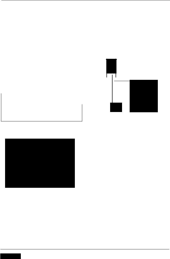
Basic Electrical Circuits
1 
 1
1
Basic Circuit Diagram
In the above circuit an electrical reservoir (the battery) is connected via a cable to a terminal on the controlling device (the switch) whose contacts are either open or closed. The other terminal on the switch is connected via a cable to the consumer (the bulb), and the other side of the bulb filament is connected to ground (earth) by another cable. The ground point is usually a part of the frame or engine, to which the battery negative terminal is also connected.
When the switch contacts are open (as shown in the diagram), the circuit is broken and no current flows. When the switch contacts are closed the circuit is made and current flows from the battery positive terminal through the switch contacts and bulb filament to ground. The frame completes the circuit to the battery negative terminal and the bulb illuminates.
Although some circuits on the circuit diagram may at first seem more complicated, it will generally be found that they can be broken down into sections which do not differ greatly from the basic circuit above.
1.14 |
SelVice Manual - Rocket III I Classic I Touring |

General Information
Circuit Diagrams
Circuit diagrams are created to provide a 'picture' of the electrical system and to identify the route taken by each individual wire through the system, in order to identify which components it feeds and which connectors the wire runs through. Circuit diagrams are an essential tool for fault finding, as it is possible to locate start and finish points for a circuit without having to manually trace the wire through the motorcycle itself. Circuits diagrams may look confusing at first but when they are studied closely they soon become logical.
Due to the complex circuits and the number of individual wires, Triumph uses two types of circuit diagram in its service manuals.
Within the manual conventional circuit diagrams are used to show the layout of the main circuits of the motorcycle. These are: Engine management/ignition, Lighting, Starting and Charging and Auxiliary and Accessory. In these diagrams no attempt is made to show the components of the system in any particular order or position in relation to the motorcycle.
•At the back of the service manual a full colour layout circuit diagram is used to show the main electrical components in a position similar to the actual position on the motorcycle.
80th of these circuit diagrams use similar symbols to illustrate the various system components and will be accompanied by a key to circuit diagram components and wiring colour codes.
Circuit diagrams also depict the inner workings of a switch cube (I.E. which wire connects to which when a switch is turned from one position to another> so that a test of that switch can be made using the wire terminals in the connector instead of disassembling the switch itself.
Glossary of Circuit Diagram Symbols
The following is a description of the symbols found in the circuit diagrams used in all Triumph Service Manuals.
Connector
This illustration is used to show all mUlti-plug type electrical connectors on Triumph circuit diagrams. The numbers in the box relate to the terminal numbers of the connector pins. On ECMs with two connectors, the number would be prefixed with the letters 'A' or '8' to
identify each connector. An additional number outside the box will identify the component.
Diode
An electrical one-way valve. Diodes allow current to flow in one direction but will not allow it to return. The arrow, which forms part of the diode symbol, indicates the direction of current flow.
Electromagnetic Winding (solenoid)
JOOOOO'-
An electromagnetic winding (or solenoid> is used to convert an electrical current into a lateral movement. This can then be used to operate switches (as used in relays> or other components such as fuel injectors or secondary air injection solenoids.
Fuse
~2 or ~3
A fuse is a device which protects a circuit in the event of a fault. The fuse will 'blow' should a short circuit occur, protecting that circuit from further damage. The number next to the fuse on the circuit diagram indicates the position of the fuse in the fusebox.
Ground or Earth Point
1 or 1
This symbol is used to show ground points. This is the negative connection to either the frame or engine, and is a common cause of intermittent faults due to loose or corroded connections.
Lamp or Bulb
This symbol is used to show all types of light bulbs. The numbers in the box relate to the terminal numbers of the
SelVice Manual - Rocket Ill/ Classic / Touring |
1.15 |

General Information
connector pins. An additional number outside the box will |
Switches |
|
|
identify the component. |
Normally |
Normally |
Change |
|
|||
LED (Light Emitting Diode) |
Open |
Closed |
Over |
Triumph use LEDs for the alarm warning light, instrument illumination and warning lights, gear change lights and rear light/brake lights on various models.
Motor
An electric motor. This could be the starter motor or a motor within an actuator, for example within the ABS modulator.
Relay
A relay is effectively an electromagnetic switch. To close the relay contacts and complete the circuit, an electromagnet in the relay is energised which causes the relay contacts to close, making the circuit complete.
Relays are used when the electrical current is too great for a mechanical switch, usually when the switching must be done quickly to prevent arcing across the switch contacts. If a mechanical switch were used, the mechanical switch contacts would quickly burn away.
Resistor
A device placed in a cable to reduce a voltage or restrict the maximum current a device can draw.
Splice
+
A hard cable joint where two or more cables are joined in the wiring harness. A potential source of both open and short circuits.
~o 0--0 o 0
or or or
,,0 o 0 o 0 Cf " '" 0
A mechanical device for completing or breaking a circuit. There are three common types of switch: Normally open, normally closed and change-over.
Tracing Circuits
The following is a description of two types of common electrical failures, and some of the methods which may be used to find them.
Open circuit
~Breakl
1
A break in an electrical circuit - current cannot flow. Usually caused by a break in a wire or cable or by a loose connection. Open circuits can often be intermittent, making diagnosis difficult.
Short circuit
A 'short cut' in an electrical circuit - current by-passes the intended circuit, either to earth or to another, different circuit. Often caused by failure of the cable insulation due to chafing or trapping of the wire. There are two different types of short circuit - short to ground and short to Vbatt.
A short to ground means that the current is going to earth before it reaches the component it is supposed to feed. These are often caused by chafing of the harness to the frame or wires trapped between a bolted component, and will often blow the fuse on that circuit.
A short to Vbatt is a short to battery voltage (12 Volts> and is caused by a live power supply wire contacting an adjacent cable. Note that it is also possible for a 5 Volt sensor reference voltage to short to an adjacent circuit,
1.16 |
SelVice Manual - Rocket III I Classic I Touring |
General Information
which can also cause electrical failures and DTCs (Diagnostic Trouble Code) to be stored.
When tracing a wire that is suspect, carefully check the circuit diagram before starting. Remember
•a wire may diverge at a splice and go off to feed other circuits. If these circuits are working, check for wiring faults from the splice onwards.
•the circuit diagram is not an accurate guide to the actual location of the parts when fitted on the bike. It is a schematic diagram of the circuits.
•particularly where engine management items are concerned, the circuit is only completed by the ECM. If the ECM is not connected, the circuit may register as open.
If there is a break in the wire, the meter will not bleep or register a resistance.
•By probing the wire in various places, the position of a high resistance or break in the wire (open circuit> can be narrowed down until it is found.
To Measure Voltage:
In the example below, the circuit voltage is being measured at the bulb positive (+) terminal.
@@
To Check Continuity:
Ensure the circuit being tested is switched off before measuring continuity. Damage to the Digital Multi Meter (DMM) may result from testing a 'live' circuit with the meter set to resistance (0).
In the example below, the ground circuit continuity is being tested from the battery to the frame.
Continuity (resistance) Check
•Locate each end of the wire.
•Set the Digital Multi Meter (DMM) to resistance check (0).
•Probe each end of the wire.
•If there is continuity, the meter will usually bleep or register the resistance of the cable.
•A high resistance figure could indicate a dirty or corroded connection.
Voltage Check
Turn the circuit to be tested 'ON'
Set the Digital Multi Meter (DMM) to Voltage check CV). Ensure the multi meter is set to dc volts for direct current circuits (most circuits) or ac volts for alternating current circuits (typically alternator output voltage tests).
Set the range of the DMM to the range best suited to the voltage of the circuit being tested (typically 20 volts for most DMMs). Refer to the DMM manufacturers instructions.
Connect the black (ground) lead of the DMM to a reliable ground connection (usually the battery or frame ground).
•Locate the positive terminal of the wire or component to be tested.
connect the red (positive) lead of the DMM to the positive terminal.
•Read the voltage from meter.
SelVice Manual - Rocket 1111 Classic I Touring |
1.17 |

General Information
Splices
Splices are probably the most common cause of wiring faults after connectors. Splices are made where two or more wires come together and diverge in different directions, usually to feed a different circuit.
To locate a splice, it is necessary to peel back the insulation and examine the splice for its integrity. The most common fault is where one of the wires at the joint has come adrift usually causing the circuit it feeds or earths to become 'dead'.
Switches
To check a switch, set the multimeter to resistance/ continuity and probe the two pins that form a closed circuit when the switch is pushed. If the switch is working correctly, the resistance should register or the meter will bleep.
Relays
All relay cases have a circuit path engraved on them showing the circuit path across the electromagnet and the switch. Before making any checks, first note the pin designations, current paths, and whether or not there is a diode in either circuit path.
Diode
86 ......--1__......
• • 87
Electromagnet
85 e--_..... |
J |
30 |
Make continuity checks across the electromagnet first, usually from pin 86 (positive) to pin 85 (negative). If a diode appears in the circuit use the diode check on the multimeter (volts scale) in the direction of current flow. If there is no diode, use the resistance check facility. An open circuit or unusually high resistance value indicates a faulty relay.
To check the switch side, apply a 12 volt supply between pins 86 and 85. With the supply connected the relay should be heard to click and there should be continuity between pins 30 and 8Z An open circuit indicates a faulty relay.
CAN (Controller Area Networking)
CAN (sometimes called CAN bus) is a protocol for data communication between Electronic Control Modules (ECMs). Each ECM on the network is connected by a single pair of twisted wires (or bus) which are used for the transmission of vehicle sensor data. By using CAN, the overall number of system sensors, and the amount of cabling required to allow ECMs to communicate with each other is greatly reduced.
This saves cost, weight and space, and makes the system more reliable, as the physical number of wires and connections is reduced.
|
|
|
Pair of Twisted |
|
|
|
|
B28 |
|
R |
Wires |
|
|
4 |
Instrument |
|
U |
|
|
||||
B27 |
|
|
|
|
s |
||
|
|
|
|
|
|||
|
|
|
|
r- |
16 |
Pack |
|
|
|
|
|
|
|||
ECM |
|
|
|
|
|
|
|
|
|
|
|
|
|
||
|
|
|
|
|
|
|
|
|
1 |
|
|
|
|
|
|
|
|
|
|
|
|
|
|
|
|
|
|
A34 |
|
|
|
|
KY |
3 |
|
|
|
||||
|
|
|
|
|
|
|
|
|
|
|
|
||
|
|
|
|
|
|
|
|
|
|
||||
|
|
|
|
|
2 |
|
|
|
|||||
|
|
|
~ Vehicle |
|
|
|
|||||||
|
|
|
|
Speed |
|||||||||
|
|
|
|
|
|
|
|
|
|
Sensor |
|||
Extract from the circuit diagram showing CAN connection between ECMs
CAN works by each ECM sending out 'packets' of information (such as engine speed or fuel consumption information) on to the network bus (note that the network must be free of data before any ECM is allowed to transmit>. This data is given a priority according to its importance (for example 'engine speed' may have a higher priority than 'Iow fuel level'), so that even if two ECMs send data at the same time, high priority information is always sent first. Lower priority data is then resent after the high priority data has been received by all ECMs on the network.
The receiving ECM confirms the data has been received correctly and that the data is valid, and this information is then used by the ECM as necessary. Specific data not required by an ECM will still be received and acknowledged as correct but then disregarded (for example if an ECM does not require 'clutch switch position' information, this data packet would be ignored).
This allows for a very high speed system of communication, which is also very reliable. Should one ECM fail or transmit corrupted or otherwise incorrect messages, none of the other ECMs on the network will be affected, and after a certain time that ECM will be prevented from transmitting further messages until the fault is rectified. This stops the ECM from clogging the network with incorrect data and preventing other messages from getting through. The fault would then be reported by a DTC (Diagnostic Trouble Code).
Triumph currently use CAN for communication between the engine ECM and the instruments.
1.18 |
SelVice Manual - Rocket Ill/ Classic / Touring |
|

General Information
Alternator/Charging System
The charging system consists of an alternator, a rectifier/ regulator assembly and the battery. The alternator is made up of two parts, the stator, which is mounted to the crankcase or the engine cover, and the rotor, mounted to the end of the crankshaft. The stator is an assembly of 18 coils, arranged into 3 phases. The rotor is a series of magnets mounted in the engine flywheel, which are arranged so as to be positioned around the outside of the stator coils. As the engine rotates the alternator produces an AC (alternating current> voltage in each of the three phases of the alternator, typically of around 35 to 40 volts AC at 4000-5000 rpm, although this figure varies between models. As the battery requires DC (direct current> voltage for correct charging, this AC voltage must be first rectified to DC current, and then regulated to the correct voltage for the battery of 14.5 ± 0.5 volts. This is done by the rectifier/regulator, which uses diodes to convert the alternator output to DC volts and limit the resulting output to the correct figure required for optimal battery charging.
If the charging circuit does not operate correctly, the following basic checks must be carried out before further diagnosis is performed:
Check the battery terminals are clean and tight
Check the frame and engine earth connections are clean, tight and free from corrosion.
•Ensure the battery is fully charged and in good condition.
Check that any fuse in the circuit is not blown and is of the correct rating (See page 18-15 for Rockett III and Classic, see page 18-16 for Rocket III Touring>.
Rectify any defects as necessary.
SelVice Manual - Rocket Ill/ Classic / Touring |
1.19 |

General Information
Diagnosis - Charging Circuit
ENSURE THE BATTERY IS IN GOOD CONDITION AND FULLY CHARGED. CHECK ALL BATTERY AND GROUND TERMINALS ARE CLEAN AND TIGHT
OK
IF
Not OK |
RECHARGE OR REPLACE FAULTY |
|
|
|
|||
|
|
BATTERY AND/OR REPAIR DIRTY/ |
|
|
|
LOOSE CONNECTIONS |
|
|
|
|
|
|
|
|
|
OK |
I |
|
|
|
|||
|
|
|
|
|
|
WITH THE ENGINE RUNNING AT |
|
|
|
Above |
|
|
|
||
|
|
AROUND 2000 RPM, MEASURE THE |
|
|
|
|
|
|
|||
|
|
|
|
|
15 Volts |
|
|
|
|||
|
|
BATTERY VOLTAGE AT THE BATTERY. |
|
|
|
|
|
FAULTY RECTIFIER! REGULATOR |
|||
|
|
|
|
|
|
|
|
||||
|
|
|
|
|
|
||||||
|
|
THE BATTERY VOLTAGE SHOULD BE |
|
|
|
|
|
|
|
||
|
|
|
14.5 ±0.5 VOLTS |
|
|
|
|
|
|
|
|
|
|
|
Below |
|
|
|
|
|
|
|
|
|
|
|
14 Volts |
, |
|
|
|
|
|
|
|
|
STOP THE ENGINE AND DISCONNECT THE |
|
|
|
|
||||||
|
|
ALTERNATOR CONNECTOR. RE-START |
|
|
|
|
|||||
|
|
THE ENGINE AND ALLOW TO IDLE. |
|
|
|
|
|||||
|
|
MEASURE THE ALTERNATING CURRENT |
|
|
|
|
|||||
|
(AC) VOLTAGE FROM THE 3 ALTERNATOR |
|
|
|
|
||||||
|
|
|
OUTPUT WIRES IN TURN. |
|
|
|
|
||||
|
THE OUTPUT VOLTAGE MUST EXCEED 10 |
|
|
|
|
||||||
|
|
VOLTS AC FROM EACH WIRE |
|
|
|
|
|||||
|
|
|
|
|
|||||||
|
|
|
|
|
|
|
|
|
|
|
|
|
|
|
Above 10 |
|
|
|
|
|
|
|
|
|
|
|
VollsAC |
|
|
|
|
|
|
|
|
|
|
|
|
|
|
|
|
|
|
|
|
|
|
|
|
|
|
|
|
|
|
|
|
|
|
RAISE THE ENGINE SPEED ABOVE |
|
|
|
|
|
|
|
||
|
|
|
4000 RPM. MEASURE THE |
|
|
|
Below 30 |
|
|||
|
|
ALTERNATING CURRENT (AC) |
|
|
|
|
|||||
|
|
|
|
|
VollsAC |
|
|||||
|
|
VOLTAGE FROM THE 3 ALTERNATOR |
|
|
|
|
|||||
|
|
|
|
|
|
|
|
FAULTY ALTERNATOR |
|||
|
|
|
OUTPUT WIRES IN TURN. |
|
|
|
|
|
|
||
|
|
|
|
|
|
|
|
|
|
||
|
|
THE OUTPUT VOLTAGE MUST NOW |
|
|
|
|
|
|
|
||
|
|
EXCEED 30 VOLTS AC FROM EACH |
|
|
|
|
|
|
|
||
|
|
|
|
|
|
|
|
|
|||
|
|
|
|
WIRE |
|
|
|
|
|
|
|
|
|
|
|
|
|
|
|
|
|
|
|
|
|
|
Above 30 |
|
|
|
|
|
|
|
|
|
|
|
VoltsAC |
r |
|
|
|
|
|||
|
|
|
|
|
|
|
|
||||
|
|
FAULTY RECTIFIER! REGULATOR |
|
|
|
|
|
|
|||
|
|
|
|
|
|
|
|
|
|
|
|
|
|
|
|
|
|
|
|
|
|
|
|
1.20 |
SelVice ManualRocket 1111 Classic 1 Touring |

General Information
Starting Circuit
All Triumph models are equipped with an electric start system. This system consists of a starter relay, starter motor, starter switch, sidestand switch, engine stop switch, clutch switch and the sprag clutch. The starter motor is connected to the starter relay and the battery by heavy duty cables in order to supply the large currents required by the motor to start the engine. When the starter button is pressed the relay is energised, which then allows current to the starter motor. The starter motor will not operate unless the clutch lever is pulled in. Also, the starter will not operate if the sidestand is down, unless the transmission is in neutral. If the starter motor does not operate, the following basic checks must be carried out before further diagnosis is performed:
•Check the engine stop switch is in the 'RUN' position.
Check the battery terminals are clean and tight
•Check the frame and engine earth connections are clean, tight and free from corrosion.
•Ensure the battery is fully charged and in good condition.
Check that any fuse in the circuit is not blown and is of the correct rating.
Using the triumph diagnostic tool, check the operation of the neutral switch or gear position sensor (if fitted), sidestand and clutch switches.
Note:
•On all new models from Daytona 675 onwards, which use a CAN connection between the instruments and the ECM, the engine will not crank if the instruments are disconnected.
Rectify any defects as necessary.
General Fault Finding - Starter Motor and Relay
|
Symptom |
Possible cause(s) |
|
|
|||
|
|
|
|
|
Starter relay does not click, starter motor does not turn |
Battery discharged or defective |
|
|
|||
|
|
|
|
|
|
|
Blown main or starter relay fuse |
|
|
|
|
|
|
|
Defective starter relay wiring or starter switch |
|
|
|
|
|
|
|
|
|
|
|
Check that the sidestand, transmission and clutch lever are |
|
|
|
positioned for engine starting I.E. transmission in neutral, |
|
|
|
|
|
|
|
clutch lever pulled in and the sidestand down |
|
|
|
|
|
|
|
Defective alarm system - ensure any alarm fitted is working |
|
|
|
correctly |
|
|
|
|
|
Starter motor turns slowly |
Battery discharged or defective |
|
|
|
|
|
|
|
|
Loose, corroded or dirty battery connections |
|
|
|
|
|
|
|
Loose, corroded or dirty starter motor or starter relay |
|
|
|
connections |
|
|
|
|
|
|
|
Defective starter motor |
|
|
|
|
|
|
|
Loose, corroded or dirty battery ground connections |
|
|
|
|
|
Starter relay clicks but engine does turn over |
Battery discharged or defective |
|
|
|
|
|
|
|
|
Crankshaft does not turn due to engine defect |
|
|
|
|
|
|
|
Defective starter motor |
|
|
|
|
|
|
|
Starter cable open circuit |
|
|
|
|
|
|
|
Defective starter relay |
|
|
|
|
|
Starter motor turns but engine does not turn over |
Starter motor or starter ring gear |
|
|
|
|
|
SelVice Manual - Rocket Ill/ Classic / Touring |
1.21 |
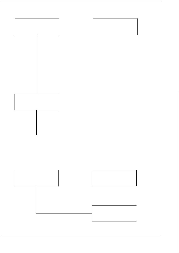
General Information
Diagnosis - Starter Circuit
WITH THE IGNITION SWITCH ON AND |
|
USING A SUITABLE HEAW DUTY |
THE ENGINE STOP SWITCH AT 'RUN', |
Clicks |
JUMPER CABLE, CONNECT THE |
CHECK FOR A CLICK AT THE STARTER 1 --------- +1STARTER POSITIVE TERMINAL TO THE |
||
RELAY WHEN THE STARTER SWITCH |
|
BATTERY POSITIVE TERMINAL |
IS PRESSED |
|
|
No Click
DISCONNECT THE STARTER RELAY SWITCH CONNECTOR. CHECK THE RELAY COIL EARTH (GROUND) WIRE
Continuity
|
|
|
|
|
|
|
|
|
|
Starter |
|
|
|
|
Starter motor |
||||
motor turns |
|
|
|
|
does not turn |
||||
|
|
|
|
|
|
|
|
|
|
|
|
LOOSE OR |
|
FAULTY |
|
||||
|
DISCONNECTED |
|
STARTER |
|
|||||
|
WIRE OR CABLE. |
|
MOTOR |
|
|||||
|
|
FAULTY |
|
|
|
|
|
||
|
|
STARTER |
|
|
|
|
|
||
|
|
RELAY/ |
|
|
|
|
|
||
|
|
SOLENOID |
|
|
|
|
|
||
|
|
|
|
|
|
|
|
|
|
|
FAULTY NEUTRAL SWITCH |
|
|
||
No |
FAULTY CLUTCH SWITCH |
|
FAULTY SIDESTAND SWITCH |
||
Continuity |
||
BAD CONTACT AT CONNECTOR |
||
|
||
|
||
|
OPEN CIRCUIT IN WIRING LOOM |
|
|
FAULTY ALARM OR ENGINE ECM (IF |
|
|
FITTED) |
|
|
||
|
|
|
|
|
|
|
FAULTY IGNITION SWITCH/ENGINE |
CONNECT THE STARTER RELAY |
No |
|
|||
|
STOP SWITCH |
||||
SWITCH CONNECTOR. MEASURE THE |
Voltage |
|
|||
|
BROKEN STARTER SWITCH CABLE |
||||
STARTER RELAY VOLTAGE AT THE |
I-------:..=~---~ |
|
|||
STARTER RELAY SWITCH |
|
|
|
BAD CONTACT AT CONNECTOR |
|
|
|
|
OPEN CIRCUIT IN WIRING LOOM |
||
CONNECTOR |
|
|
|
||
|
|
|
FAULTY ALARM |
||
|
|
|
|
|
|
Voltage |
|
|
|
|
|
Measured |
|
|
|
|
|
|
|
|
|
|
|
CHECK THE STARTER RELAY |
Normal |
LOOSE OR POOR CONTACT AT |
|
||
OPERATION |
|
STARTER RELAY |
Abnormal
FAULTY STARTER RELAY
1.22 |
SelVice ManualRocket III I Classic I Touring |
 Loading...