

Page 1
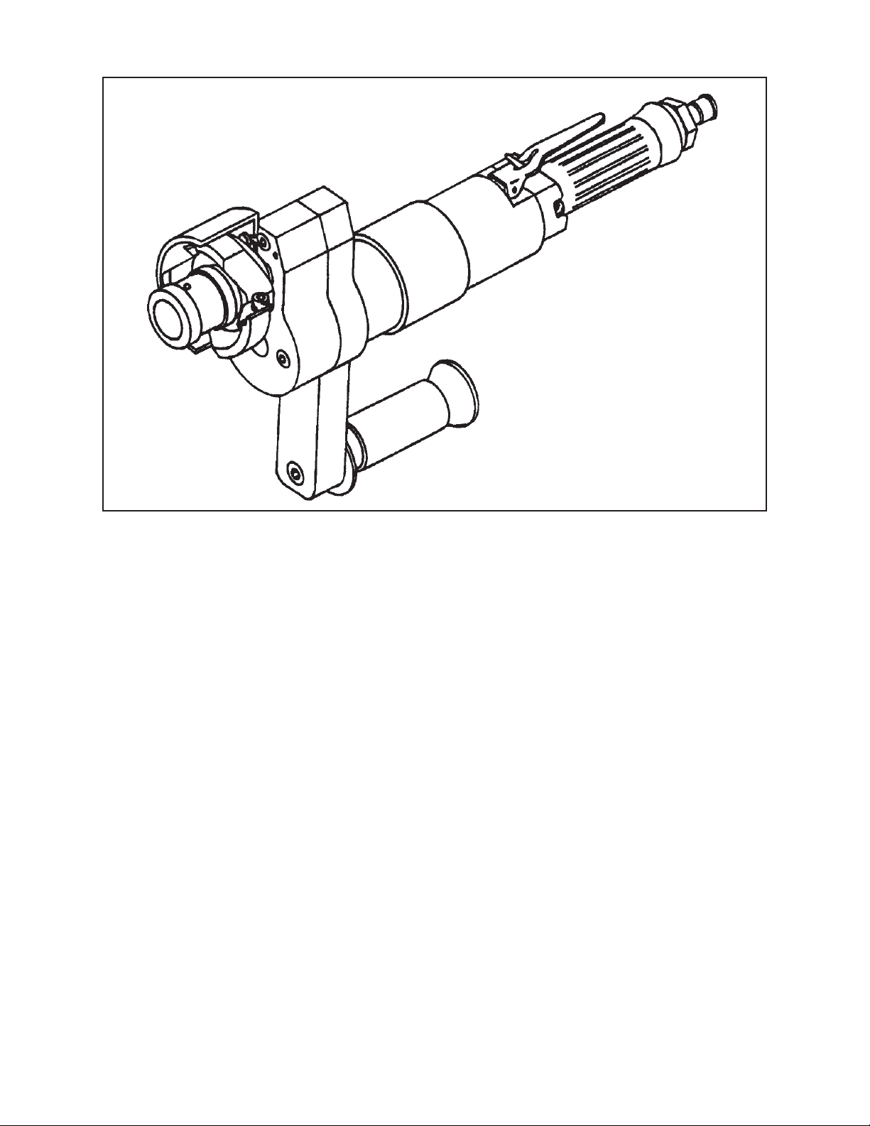
TABLE OF CONTENTS
CUSTOMER MESSAGE Inside Front Cover
SAFETY PRECAUTIONS 3
92-0131 Rev. 960503
, Rapid End Prep Machine
TM
Model 103 REP
GENERAL DESCRIPTION 6
SPECIFICATIONS 7
MAINTENANCE 8
OPERATION 10
OPERATION USING THE CROSS TRACK ASSY. 14
PILOT MANDREL & CUTTER HEAD KIT USAGE CHART 17
CUTTER HEAD KITS 24
TOOL INSERTS 27
TROUBLE SHOOTING 28
ACCESSORIES 30
ILLUSTRATED PARTS BREAKDOWN 31
TOOL BIT RESHARPENING POLICY Inside Back Cover
Page 2

Copyright 2005
Proprietary property of TRI TOOL Inc.
No reproduction, use, or duplication of the information
shown hereon is permitted without the express written
consent of TRI TOOL Inc.
Page 3

SAFETY PRECAUTIONS
IN GENERAL
When using rotating head cutting equipment, basic safety precautions should always
be followed to reduce the risk of personal injury.
Operate this tool only in accordance with specific operating instructions.
Do not override the deadman switch on the power unit. Locking down, ob-
WARNING:
DRESS CONSIDERATIONS
structing, or in any way defeating the deadman switch on the power drive unit
may result in serious injury.
Model 103 REP
TM
, Rapid End Prep Machine
Use standard safety equipment. Hard hats, safety shoes, safety harnesses, protective clothes, and other safety devices should always be used when appropriate.
Use safety glasses. Do not operate cutting tools without eye protection.
Dress properly. Do not wear loose clothing or jewelry. They can be caught in rotating and moving parts. Avoid slippery floors or wear nonskid footwear. If you have
long hair, wear protective hair covering to contain it.
WORK AREA
Keep the work area clean. Cluttered work areas and benches invite injuries.
Consider the work area environment. Keep the area well lit. Keep electrical cords,
cables, rags, rigging straps, and etc. clear of rotating equipment. Do not use powercutting tools in the presence of flammable liquids and gasses.
Keep visitors away. Do not let visitors or untrained personnel at or near operating
tools. Enforce eye protection requirements for all observers.
Do not over reach. Keep proper footing at all times.
Stay alert. Watch what you are doing. Use common sense. Do not operate tools
when you are tired.
92-0131 : Rev. 960503
3
Page 4

TRI TOOL INC.
TOOL CARE
Maintain tools with care. Keep tools in good operating condition. Sharp tool bits
perform better and safer than dull tool bits. Well maintained tools function properly
when needed.
Check for damaged parts. If a tool has malfunctioned, been dropped or hit, it must
be checked for damage. Run no-load tests and feed function checks. Do a complete visual inspection.
Electric motors. Use only with proper AC voltage power sources and observe all
normal electric shock hazard procedures.
Do not abuse power and control cords. Pulling or running over cords and cables
can result in electrical shock hazards and malfunctions. Keep control and power
cords out of all cutting fluids and water.
Hydraulic drives. Observe proper procedures for electrically driven power sources.
Avoid damage to hydraulic lines. Keep quick-disconnects clean. Grit contamination
causes malfunctions.
Air tools. Check the exhaust muffler. Broken or damaged mufflers can restrict air
flow or cause excessive noise. Use air motors only with a filtered, lubricated and
regulated air supply. Dirty air, low-pressure air or over pressure air will cause malfunctions, including delayed starting.
AREA EQUIPMENT
Secure work. Whenever possible use clamps, vises, chains and straps to secure
pipe.
Make sure the tool is secured; it is safer to have both hands free to operate the tool.
TOOL USE
Use the right tool and tool bit for the job. Do not use a tool, which is incorrect for the
job you are doing.
Keep the tool bits fully engaged in the tool bit holders. Loose bits are a safety hazard.
4
92-0131 : Rev. 960503
Page 5

TM
Model 103 REP
Disconnect power supply during setup and maintenance. Use all ‘Stop’ or Shut off’
features available when changing or adjusting tool bits, maintaining the tool, or when
the tool is not in use.
Remove adjusting keys and wrenches before applying power to the equipment.
Develop a habit of checking the tool before turning it on to make sure that all keys
and wrenches have been removed.
Do not force tools. Tools and tool bits function better and safer when used at the
feed and speed rate for which they were designed.
Do not reach into rotating equipment. Do not reach into the rotating head stock to
clear chips, to make adjustments, or to check surface finish. A machine designed to
cut steel will not stop for a hand or an arm.
Handle chips with care. Chips have very sharp edges and are hot. Do not try to pull
chips apart with are hands; they are very tough.
, Rapid End Prep Machine
Avoid unintentional starts. Do not carry or handle tools with your hand on the operating switches or levers. Do not lay the tool down in a manner that will start the
drive. Do not allow the tool to flip around or move when adjusting or changing tool
bits.
Store idle tools properly. Disconnect tools from the power source and store in a safe
place. Remove tool bits for safe handling of the tool.
92-0131 : Rev. 960503
5
Page 6

TRI TOOL INC.
GENERAL DESCRIPTION
The Model 103 REPTM Rapid End Prep Machine is a small, lightweight, beveling tool
designed for beveling the ends of pipe or tubing in preparation for welding.
The Model 103 REP
the pipe or tube by means of a rigid, self-centering Pilot Mandrel.
There are various Pilot Mandrels which are available that will position the Model 103
TM
REP
from .42” through 3.16” (10.7 mm through 80.3 mm).
The Model 103 REPTM generates low torque during the machining operations.
The Model 103 REPTM features a Cutting Head Spindle offset from the motor to allow
installation and cutting of boiler tubes in a water wall panel.
Rapid End Prep Machine to pipe and/or tubing having an inside diameter range
TM
Rapid End Prep Machine is mounted to the inside diameter of
The Model 103 REPTM features eight different diameter Cutting Heads which allow the
operator to select the optimum size head for the operation.
The smallest is the 1.85” (47.0 mm) dia Cutting Head which provides for a
minimum radial clearance.
The largest is the 3.60” (91.4 mm) dia Cutting Head which requires the most
radial clearance, but increases the Tool Bit capabilities and size of pipe or
tubing which may be effectively end prepped.
The end prep geometry is built into the Cutting Heads.
A Chip Deflection Shield is supplied with each Cutting Head.
6
92-0131 : Rev. 960503
Page 7
Model 103 REP
SPECIFICATIONS
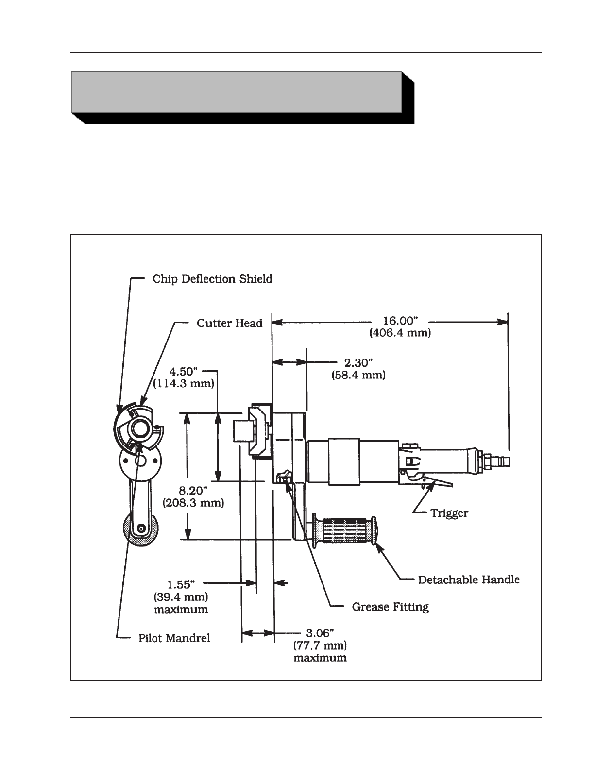
Model 103 REP with an Air Motor
Weight: 9 to 15 pounds (4 to 7 kg), depending on Cutting Head and Pilot size
Power Requirements: 75 cfm at 90 psi (35 L/s at 621 kPa)
Envelope, Model 103REP, Rapid End Prep Machine
TM
, Rapid End Prep Machine
92-0131 : Rev. 960503
7
Page 8
TRI TOOL INC.
MAINTENANCE
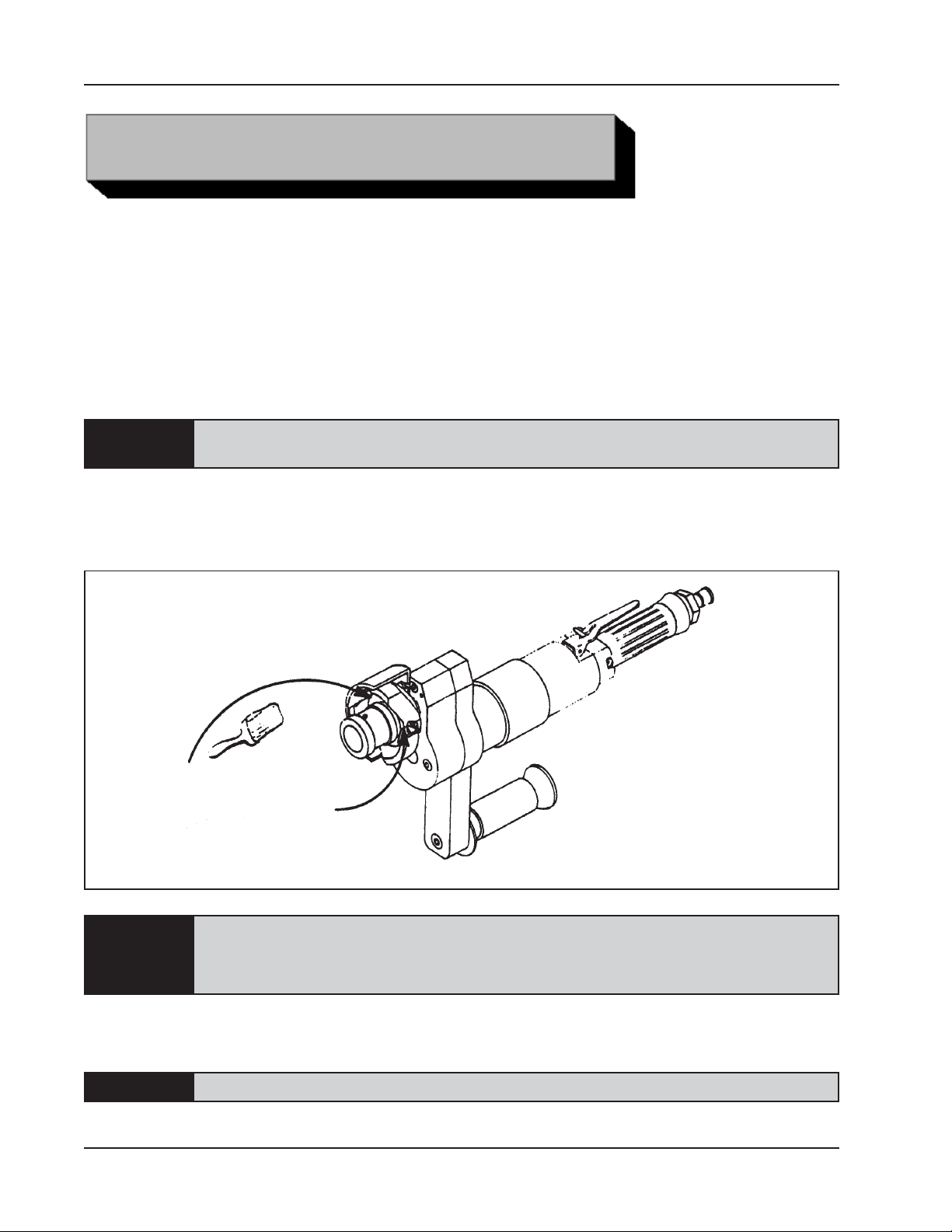
All components should be cleaned and coated with a light film of oil prior to use.
Use a clean, non-detergent oil, preferably SAE 10 (90 SSU) or lighter, or oil which is
specified for the Air Motor.
AIR SUPPLY FOR THE MODEL 103 REPTM WITH AIR MOTOR
An adequate filter, regulator, and lubricator must be used in the air supply line.
NOTE:
If the Model 103 REPTM is operated in the vertical position (Cutting Head up), it should
be turned upside down and the chips and/or other debris removed after each bevel has
been completed.
The motor warranty is void if damage occurs from contaminated air or lack of
lubrication.
Clean Up
8
Tool life may be severely shortened, unless chips and/or other debris that have
NOTE:
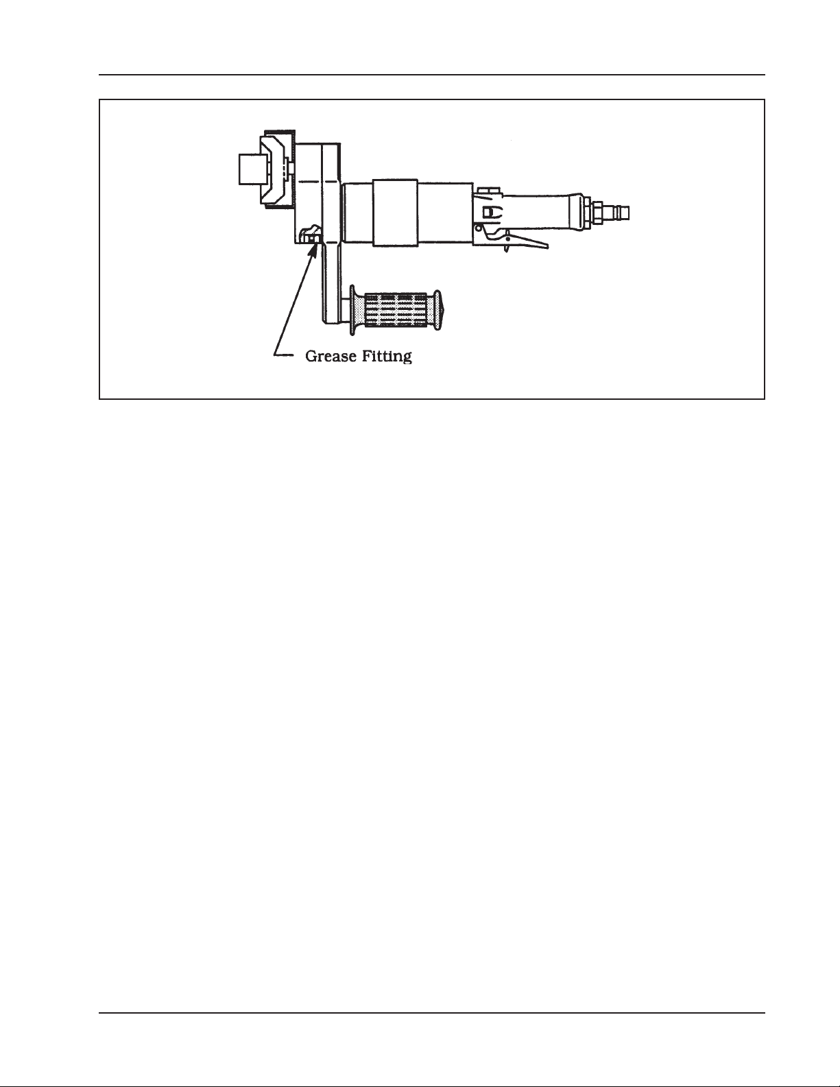
After every 10 hours of operation the Drive Gears should be re-lubricated. See the
picture ‘Grease’.
NOTE:
been deposited on the Cutting Head during the machining operation are
removed.
Use TRI TOOL Inc. Lubricant (P/N 68-0019), this is a Lithium base white grease.
92-0131 : Rev. 960503
Page 9
TM
Model 103 REP
, Rapid End Prep Machine
Grease
In order to lubricate the Gears, a grease fitting has been provided.
After every 50 hours of operation, the Model 103 REPTM should be disassembled and
inspected for worn parts.
All Gears and Bearings should be cleaned and re-lubricated with a Lithium base white
grease, such as TRI TOOL Inc. lubricant (P/N 68-0019).
92-0131 : Rev. 960503
9
Page 10
TRI TOOL INC.
Read the operation instructions carefully before attempting to operate the Model 103
REPTM.
Use eye protection at all times when operating the Model 103 REP
Select the recommended Cutter Head Kit for the outside diameter to be machined.
Refer to the section on Cutter Head Kits.
Select the recommended Pilot Mandrel for the pipe size to be machined. Refer to the
section on Pilot Mandrels.
OPERATION
TM
.
NOTE:
For special applications, i.e., very thin wall, extra heavy wall or tough materials, please
contact TRI TOOL Inc. for assistance in the selection.
Attach the cover (part of the Cutter Head Kit) by using the two Button Head Screws
which fit into the slots.
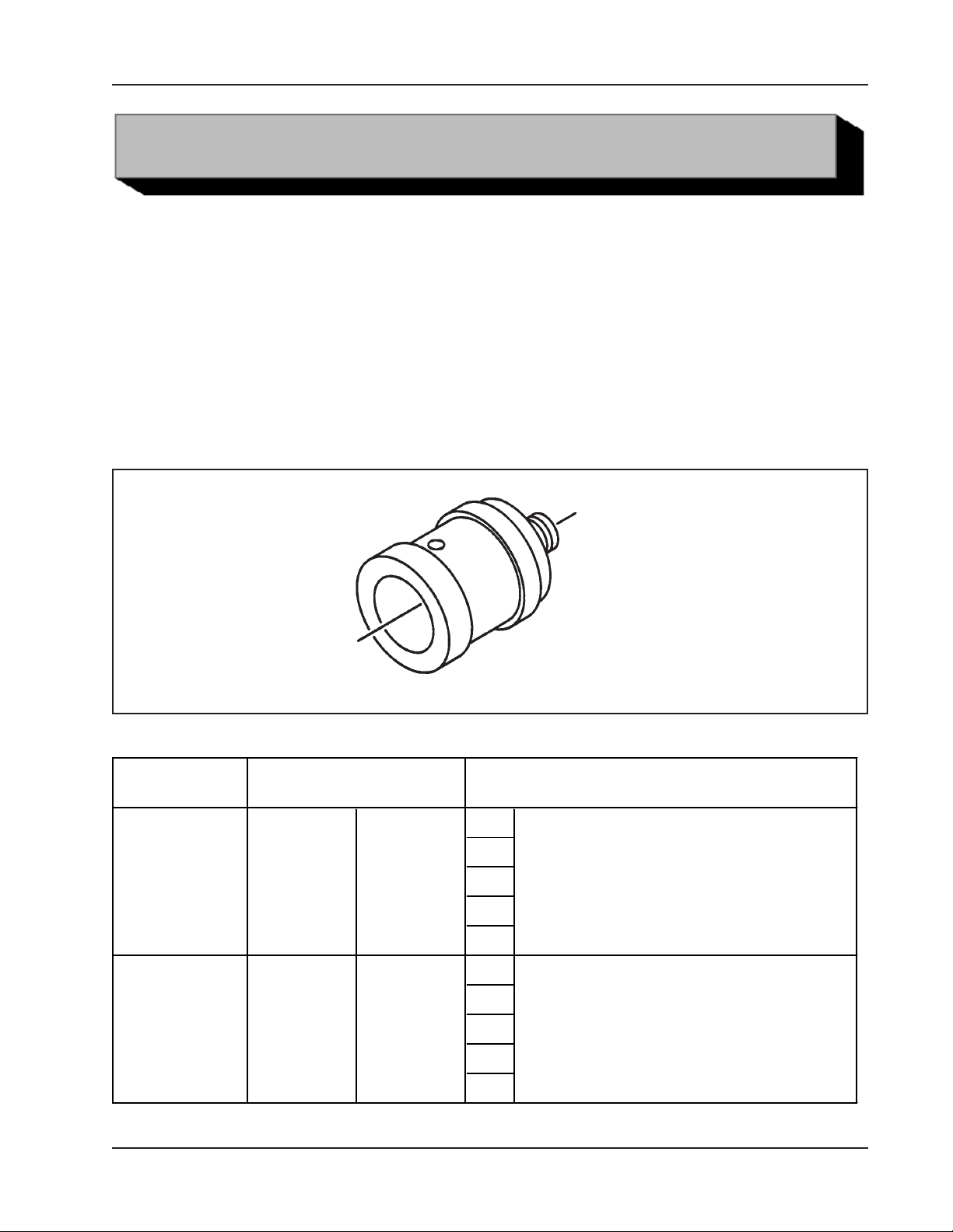
Pilot Mandrels are recommended based on the inside diameters of the pipe or
tubing to be machined.
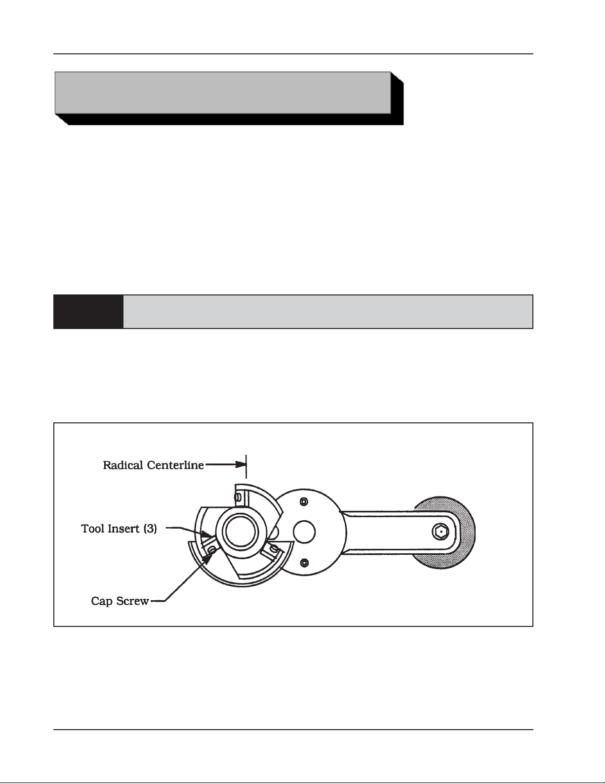
Tool Insert Positioning
10
Screw the Cutter Head onto the threaded output shaft of the Model 103 REP
End Prep Machine.
Use the 11/16” Wrenches (supplied) to tighten.
92-0131 : Rev. 960503
TM
Rapid
Page 11
TM
Model 103 REP
Screw the Pilot Mandrel into the Cutter Head and tighten with the 11/16” wrench and
1/4” Wrench (supplied).
Insert the 1/4-20 UNC left-hand thread Screw (supplied with Cutter Head Kit) through
the Pilot Mandrel and the Cutter Head into the Cutter Shaft.
This Screw prevents the Pilot Mandrel from spinning off during deceleration of the
Cutter Head.
, Rapid End Prep Machine
CAUTION:
The Cutter Head may spin off.
Select the Tool Inserts required to machine the pipe. Refer to the Tool Insert list in the
section ‘Cutter Head Kits’.
WARNING:
Insert the Tool Inserts into the slots in the Cutting Head.
CAUTION:
CAUTION:
Tighten the Cap Screws to secure the Tool Inserts to the Cutting Head. Refer to the
picture ‘Tool Insert positioning’.
Never attempt to run the Model 103 REPTM without the Pilot Mandrel and Lock
Screw installed.
Use of dull or improperly designed Tool Inserts may result in poor performance
and may constitute abuse of this machine and therefore voids the TRI TOOL Inc.
factory warranty.
The cutting edge of the Tool Insets must be located on the radial centerline.
Refer to the picture ‘Tool Insert positioning’.
Check each Tool Insert for proper installation. Refer to the picture ‘Tool Insert
positioning’.
Insure that there is rotational clearance between the Pilot Mandrel and Tool Inserts.
Attach the proper air supply line to the Model 103 REPTM Rapid End Prep Machine.
NOTE:
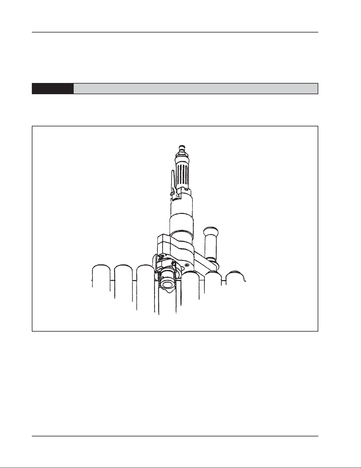
Slide the Model 103 REPTM with the Pilot Mandrel installed, Pilot Mandrel end first into
the pipe or tube to receive the end preparation. Refer to the picture ‘Mounting the
Model 103 REPTM on a water wall’.
Make sure that the Tool Inserts are not contacting the end of the pipe or tube before the
Model 103 REPTM Rapid End Prep Machine begins the end prep.
Use an Adequate in-line filter, regulator, and lubricator.
92-0131 : Rev. 960503
11
Page 12
TRI TOOL INC.
Depress the Air Motor Hand Lever.
Lower the Model 103 REP
TM
into the pipe or tube.
CAUTION:
The actual machining operation will begin when the Tool Inserts contact the pipe.
If the pipe end is not square to the pipe axis, the Tool Inserts will contact only a small
segment of the pipe during each revolution.
Mounting the Model 103 REP on a water wall
12
To avoid Tool Insert damage, the feed rate should be very slow until the Tool Inserts are
contacting the pipe continually during at least one full revolution.
Continue feeding the Model 103 REP
TM
into the pipe or tube until the end is completely
machined.
Stop feeding and allow the Cutting Head to rotate to improve the finish of the prep
surface.
Stop the tool rotation.
92-0131 : Rev. 960503
Page 13

TM
Model 103 REP
, Rapid End Prep Machine
Release the Air Motor Hand Lever.
TM
Remove the Model 103 REP
completely from the pipe or tube.
If the next bevel is to be identical to the previous bevel, follow the sequence starting at
the beginning of this section, beginning at ‘Attach the proper air supply line’.
If the next bevel is to be different than the previous bevel, follow the sequence starting at
the beginning of this section, beginning ‘Select the recommended Cutter Head Kit’.
92-0131 : Rev. 960503
13
Page 14
TRI TOOL INC.
OPERATION USING THE CROSS TRACK ASSY.
If the Model 512A1 Panel Saw has been used to cut a window in the water wall and the
64” (1.6 mm) Track is still in place than go ahead to ‘Slide the Cross Track Assy’.
INSTALLING THE TRACK ONTO THE WORK.
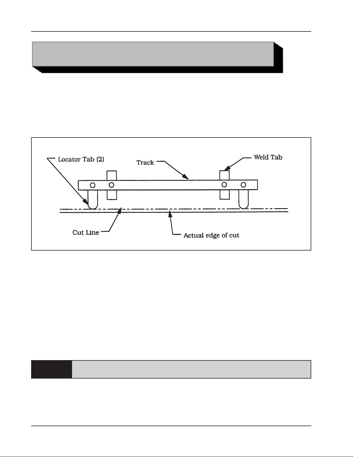
Bolt a Locator Tab onto the Track at each end perpendicular to the Track.
Track Positioning with the Locator Tabs
14
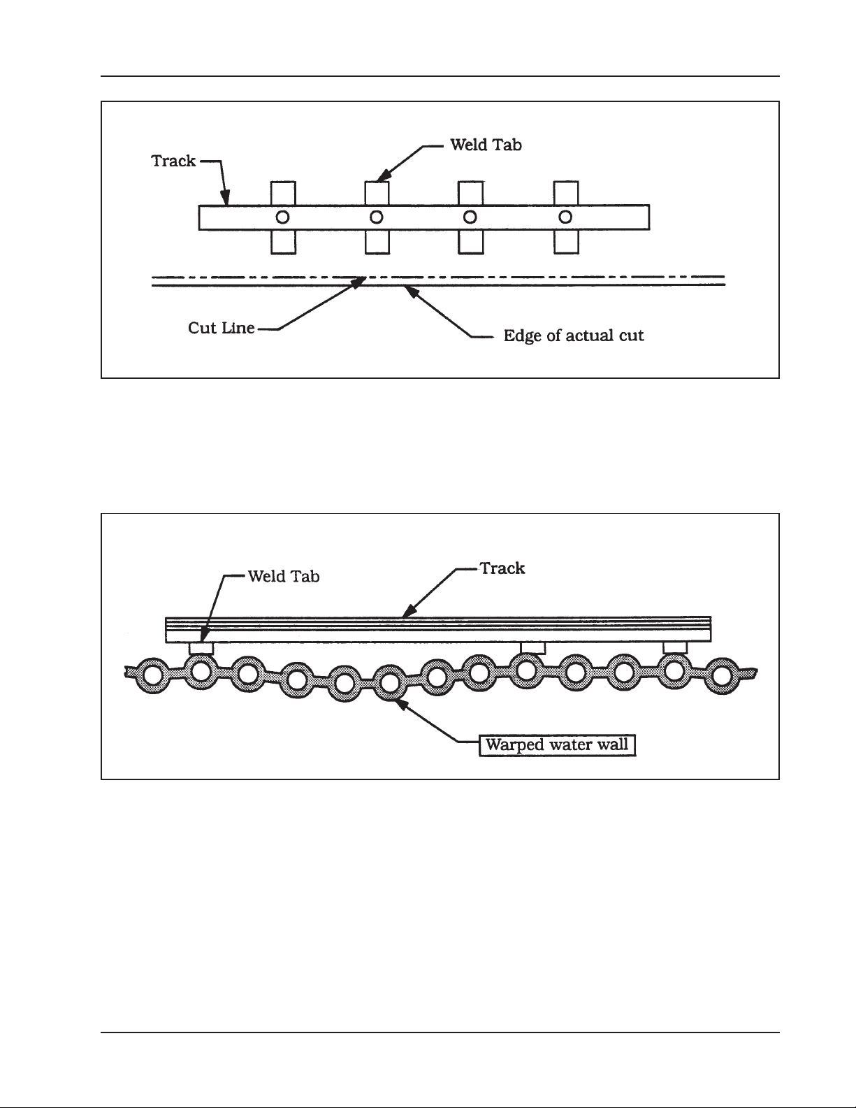
Bolt a Weld Tab onto both ends of the Track in the next position toward the center from
the Locator tab.
Place the Track on the work.
Line up the Locator Tabs perpendicular to and touching the cut line.
Weld both of the Weld Tabs down. Refer to the picture ‘Weld Tab locations on the
Track’.
Weld Tabs may be rotated as required to make contact with the tops of the tubes.
NOTE:
The Weld Tabs do not have to be 90O to the Track.
Remove the Locator Tabs from the Track.
When welding Weld Tabs to tubes is not permissible, small stacks (not supplied)
may be welded to the membrane and then to the Weld Tabs.
92-0131 : Rev. 960503
Page 15
TM
Model 103 REP
, Rapid End Prep Machine
Weld Tab Locations on the Track
Bolt Weld tabs to the Track at the remaining positions, as required.
Weld the Weld Tabs to the work where possible.
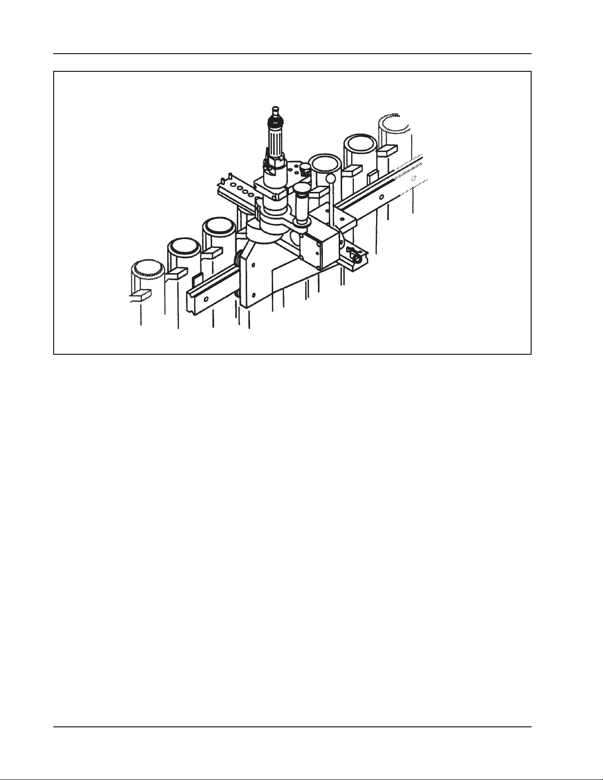
Slide the Cross-Track Assy onto the 64” (1.6 m) Track.
Track Set-up on a Warped Water Wall
It may be required to remove the 23” (.6 m) Track from the top of the Cross-Track Assy
in order to put the Cross-Track Assy onto the 64” (1.6 m) Track.
Remove the two Cap Screws which retain the 23” (.6 m) Track to the top of the CrossTrack Assy.
LOADING THE MODEL 103 REPTM ONTO THE REP ADAPTOR ASSY.
If the Model 103 REPTM is already loaded into the REP Adapter Assy then go to ‘Slide
the Track Adapter Assy onto the Cross Track Assy’.
92-0131 : Rev. 960503
15
Page 16
TRI TOOL INC.
Rapid End Prep Machine Mounted on the Adaptor Assembly
First prepare the Model 103 REPTM in the configuration required for the job at hand.
Refer to the Operating Instructions; ‘Select the recommended Pilot Mandrel’.
Loosen the two Cap Screws, which hold the Clamping Plate together.
Remove the part of the Clamping Plate in which the Cap Screws are held.
Install the Model 103 REPTM into the Clamping Plate and reinstall the other part of the
Clamping Plate and tighten the Cap Screws to hold the Model 103 REPTM in place.
SLIDE THE TRACK ADAPTER ASSY ONTO THE CROSS-TRACK ASSY
Slide the Cross-Track Assy along the 64” (1.6 m) Track to the desired location.
Slide the Track Adapter Assy along the 23” (.6 m) Track until the Model 103 REPTM is
located directly over the tube to be worked on.
Rotating the Handle on the REP Adapter Assy will cause the Model 103 REPTM to be
lowered into the end of the tube.
See the Previous Section for the machining operation.
16
92-0131 : Rev. 960503
Page 17
TM
g
Model 103 REP
, Rapid End Prep Machine
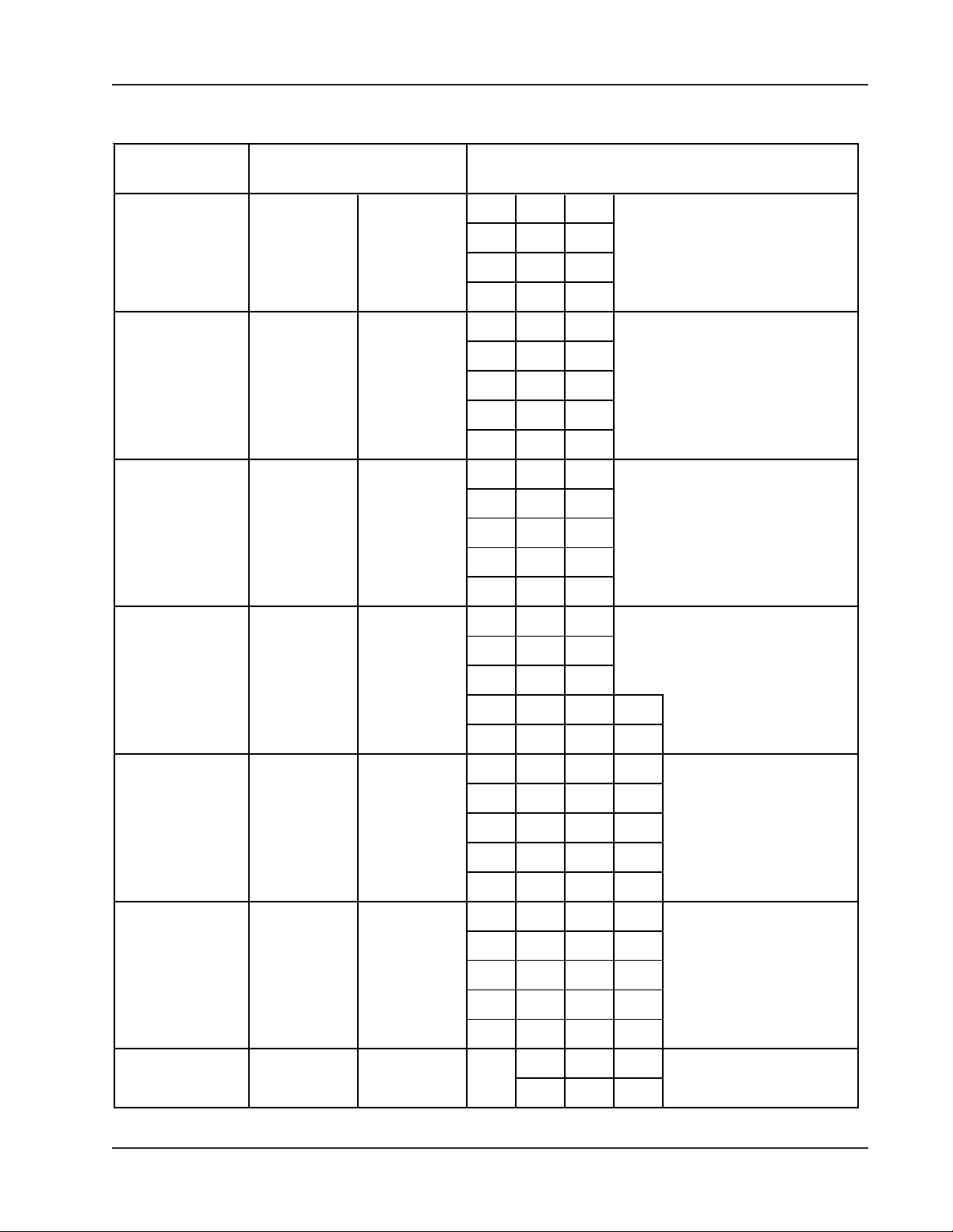
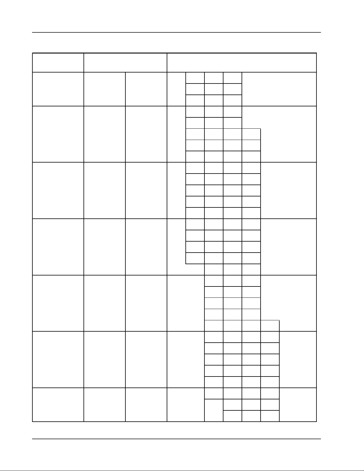
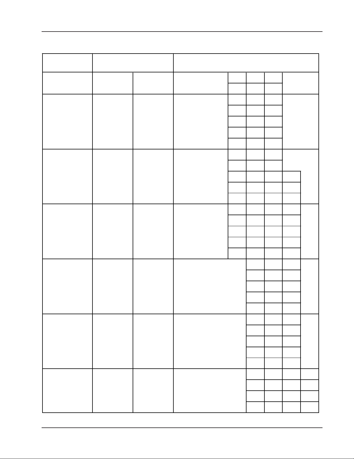
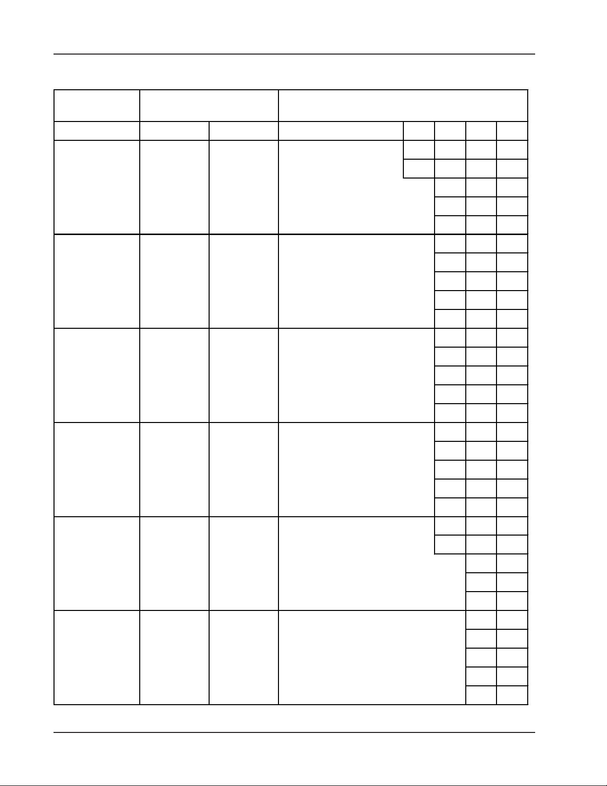
PILOT MANDREL & CUTTER HEAD KIT USAGE CHART
Recommended clearance of Pilot Mandrel to actual I.D. of pipe or tube is .015”
(.38 mm) minimum to .050” (1.27 mm) maximum.
WALL THICKNESS CAPACITY
.35” (8.9 mm) with #1 and #2 Cutter Heads
.45” (11.4 mm) with #3 through #8 Cutter Heads
If radial clearance is a problem, use smallest Cutter Head available for Pilot Mandrel
selected.
Pilot Mandrel
Pilot Mandrel Per Cutting Head Function
Pilot
P/N
13-0080 .420" 10.7 mm 1
13-0081 .435" 11.0 mm 1
13-0082 .450" 11.4 mm 1
13-0083 .465" 11.8 mm 1
13-0084 .480" 12.2 mm 1
13-0085 .495" 12.6 mm 1
13-0086 .510" 13.0 mm 1
13-0087 .525" 13.3 mm 1
13-0088 .540" 13.7 mm 1
13-0089 .555" 14.1 mm 1
Pilot
Size
Chart Continued on next page
92-0131 : Rev. 960503
Cuttin
Functions with
Head Kit Numbers
17
Page 18
TRI TOOL INC.
g
Pilot Mandrel Per Cutting Head Function
Pilot
P/N
13-0090 .570" 14.5 mm 1
13-0091 .585" 14.9 mm 1
13-0092 .600" 15.2 mm 1
13-0093 .615" 15.6 mm 1
13-0094 .630" 16.0 mm 1
13-0095 .645" 16.4 mm 1
13-0096 .660" 16.8 mm 1
13-0097 .675" 17.1 mm 1
13-0098 .690" 17.5 mm 1
13-0099 .705" 17.9 mm 1
13-0100 .720" 18.3 mm 1
13-0101 .735" 18.7 mm 1
13-0102 .745" 18.9 mm 1
13-0103 .750" 19.1 mm 1
Pilot
Size
Cuttin
Functions with
Head Kit Numbers
13-0104 .760" 19.3 mm 1
13-0105 .775" 19.7 mm 1
13-0106 .790" 20.1 mm 1
13-0107 .805" 20.4 mm 1
13-0108 .820" 20.8 mm 1
13-0109 .835" 21.2 mm 1
13-0110 .850" 21.6 mm 1
13-0111 .865" 22.0 mm 1
13-0112 .880" 22.4 mm 1
13-0113 .895" 22.7 mm 1
13-0114 .910" 23.1 mm 1
13-0115 .925" 23.5 mm 1
13-0116 .940" 23.9 mm 1
13-0117 .955" 24.3 mm 1
13-0118 .970" 24.6 mm 1
13-0119 .985" 25.0 mm 1
13-0120 .995" 25.3 mm 1 2 3
Chart Continued on next page
18
92-0131 : Rev. 960503
Page 19
Model 103 REP
g
Pilot Mandrel Per Cutting Head Function
TM
, Rapid End Prep Machine
Pilot
P/N
13-0121 1.000" 25.4 mm 1 2 3
13-0122 1.010" 25.7 mm 1 2 3
13-0123 1.025" 26.0 mm 1 2 3
13-0124 1.040" 26.4 mm 1 2 3
13-0125 1.055" 26.8 mm 1 2 3
13-0126 1.070" 27.2 mm 1 2 3
13-0127 1.085" 27.6 mm 1 2 3
13-0128 1.100" 27.9 mm 1 2 3
13-0129 1.115" 28.3 mm 1 2 3
13-0130 1.130" 28.7 mm 1 2 3
13-0131 1.145" 29.1 mm 1 2 3
13-0132 1.160" 29.5 mm 1 2 3
13-0133 1.175" 29.8 mm 1 2 3
13-0134 1.190" 30.2 mm 1 2 3
Pilot
Size
Cuttin
Functions with
Head Kit Numbers
13-0135 1.205" 30.6 mm 1 2 3
13-0136 1.220" 31.0 mm 1 2 3
13-0137 1.235" 31.4 mm 1 2 3
13-0138 1.245" 31.6 mm 1234
13-0139 1.250" 31.8 mm 1234
13-0140 1.260" 32.0 mm 1234
13-0141 1.275" 32.4 mm 1234
13-0142 1.290" 32.8 mm 1234
13-0143 1.305" 33.1 mm 1234
13-0144 1.320" 33.5 mm 1234
13-0145 1.335" 33.9 mm 1234
13-0146 1.350" 34.3 mm 1234
13-0147 1.365" 34.7 mm 1234
13-0148 1.380" 35.1 mm 1234
13-0149 1.395" 35.4 mm 1234
13-0150 1.410" 35.8 mm 2 3 4
13-0151 1.425" 36.2 mm 2 3 4
Chart Continued on next page
92-0131 : Rev. 960503
19
Page 20
TRI TOOL INC.
g
Pilot Mandrel Per Cutting Head Function
Pilot
P/N
13-0152 1.440" 36.6 mm 2 3 4
13-0153 1.455" 37.0 mm 2 3 4
13-0154 1.470" 37.3 mm 2 3 4
13-0155 1.485" 37.7 mm 2 3 4
13-0156 1.495" 38.0 mm 2 3 4
13-0157 1.500" 38.1 mm 2345
13-0158 1.510" 38.4 mm 2345
13-0159 1.525" 38.7 mm 2345
13-0160 1.540" 39.1 mm 2345
13-0161 1.555" 39.5 mm 2345
13-0162 1.570" 39.9 mm 2345
13-0163 1.585" 40.3 mm 2345
13-0164 1.600" 40.6 mm 2345
13-0165 1.615" 41.0 mm 2345
Pilot
Size
Cuttin
Functions with
Head Kit Numbers
13-0166 1.630" 41.4 mm 2345
13-0167 1.645" 41.8 mm 2345
13-0168 1.660" 42.2 mm 2345
13-0169 1.675" 42.5 mm 3 4 5
13-0170 1.690" 42.9 mm 3 4 5
13-0171 1.705" 43.3 mm 3 4 5
13-0172 1.720" 43.7 mm 3 4 5
13-0173 1.735" 44.1 mm 3 4 5
13-0174 1.745" 44.3 mm 3456
13-0175 1.750" 44.5 mm 3456
13-0176 1.760" 44.7 mm 3456
13-0177 1.775" 45.1 mm 3456
13-0178 1.790" 45.5 mm 3456
13-0179 1.805" 45.8 mm 3456
13-0180 1.820" 46.2 mm 3456
13-0181 1.835" 46.6 mm 3456
13-0182 1.850" 47.0 mm 3456
Chart Continued on next page
20
92-0131 : Rev. 960503
Page 21
Model 103 REP
g
Pilot Mandrel Per Cutting Head Function
TM
, Rapid End Prep Machine
Pilot
P/N
13-0183 1.865" 47.4 mm 4 5 6
13-0184 1.880" 47.8 mm 4 5 6
13-0185 1.895" 48.1 mm 4 5 6
13-0186 1.910" 48.5 mm 4 5 6
13-0187 1.925" 48.9 mm 4 5 6
13-0188 1.940" 49.3 mm 4 5 6
13-0189 1.955" 49.7 mm 4 5 6
13-0190 1.970" 50.0 mm 4 5 6
13-0191 1.985" 50.4 mm 4 5 6
13-0192 1.995" 50.7 mm 4567
13-0193 2.000" 50.8 mm 4567
13-0194 2.010" 51.1 mm 4567
13-0195 2.025" 51.4 mm 4567
13-0196 2.040" 51.8 mm 4567
Pilot
Size
Cuttin
Functions with
Head Kit Numbers
13-0197 2.055" 52.2 mm 4567
13-0198 2.070" 52.6 mm 4567
13-0199 2.085" 53.0 mm 4567
13-0200 2.100" 53.3 mm 5 6 7
13-0201 2.115" 53.7 mm 5 6 7
13-0202 2.130" 54.1 mm 5 6 7
13-0203 2.145" 54.5 mm 5 6 7
13-0204 2.160" 54.9 mm 5 6 7
13-0205 2.175" 55.2 mm 5 6 7
13-0206 2.190" 55.6 mm 5 6 7
13-0207 2.205" 56.0 mm 5 6 7
13-0208 2.220" 56.4 mm 5 6 7
13-0209 2.235" 56.8 mm 5 6 7
13-0210 2.245" 57.0 mm 5678
13-0211 2.250" 57.2 mm 5678
13-0212 2.260" 57.4 mm 5678
13-0213 2.275" 57.8 mm 5678
Chart Continued on next page
92-0131 : Rev. 960503
21
Page 22
TRI TOOL INC.
g
Pilot Mandrel Per Cutting Head Function
Pilot
P/N
13-0214 2.290" 58.2 mm 5678
13-0215 2.305" 58.5 mm 5678
13-0216 2.320" 58.9 mm 5678
13-0217 2.335" 59.3 mm 6 7 8
13-0218 2.350" 59.7 mm 6 7 8
13-0219 2.365" 60.1 mm 6 7 8
13-0220 2.380" 60.5 mm 6 7 8
13-0221 2.395" 60.8 mm 6 7 8
13-0222 2.410" 61.2 mm 6 7 8
13-0223 2.425" 61.6 mm 6 7 8
13-0224 2.440" 62.0 mm 6 7 8
13-0225 2.455" 62.4 mm 6 7 8
13-0226 2.470" 62.7 mm 6 7 8
13-0227 2.485" 63.1 mm 6 7 8
Pilot
Size
Cuttin
Functions with
Head Kit Numbers
13-0228 2.495" 63.4 mm 6 7 8
13-0229 2.500" 63.5 mm 6 7 8
13-0230 2.510" 63.8 mm 6 7 8
13-0231 2.525" 64.1 mm 6 7 8
13-0232 2.540" 64.5 mm 6 7 8
13-0233 2.555" 64.9 mm 6 7 8
13-0234 2.570" 65.3 mm 6 7 8
13-0235 2.585" 65.7 mm 6 7 8
13-0236 2.600" 66.0 mm 6 7 8
13-0237 2.615" 66.4 mm 7 8
13-0238 2.630" 66.8 mm 7 8
13-0239 2.645" 67.2 mm 7 8
13-0240 2.660" 67.6 mm 7 8
13-0241 2.675" 67.9 mm 7 8
13-0242 2.690" 68.3 mm 7 8
13-0243 2.705" 68.7 mm 7 8
13-0244 2.720" 69.1 mm 7 8
Chart Continued on next page
22
92-0131 : Rev. 960503
Page 23
Model 103 REP
g
Pilot Mandrel Per Cutting Head Function
TM
, Rapid End Prep Machine
Pilot
P/N
13-0245 2.735" 69.5 mm 7 8
13-0246 2.750" 69.9 mm 7 8
13-0247 2.760" 70.1 mm 7 8
13-0248 2.775" 70.5 mm 7 8
13-0249 2.790" 70.9 mm 7 8
13-0250 2.805" 71.2 mm 7 8
13-0251 2.820" 71.6 mm 7 8
13-0252 2.835" 72.00 mm 7 8
13-0253 2.850" 72.4 mm 8
13-0254 2.865" 72.8 mm 8
13-0255 2.880" 73.2 mm 8
13-0256 2.895" 73.5 mm 8
13-0257 2.910" 73.9 mm 8
13-0258 2.925" 74.3 mm 8
Pilot
Size
Cuttin
Functions with
Head Kit Numbers
13-0259 2.940" 74.7 mm 8
13-0260 2.955" 75.1 mm 8
13-0261 2.970" 75.4 mm 8
13-0262 2.985" 75.8 mm 8
13-0263 3.000" 76.2 mm 8
13-0264 3.010" 76.5 mm 8
13-0265 3.025" 76.8 mm 8
13-0266 3.040" 77.2 mm 8
13-0267 3.055" 77.6 mm 8
13-0268 3.070" 78.0 mm 8
13-0269 3.085" 78.4 mm 8
13-0270 3.100" 78.7 mm 8
13-0271 3.115" 79.1 mm 8
13-0272 3.130" 79.5 mm 8
13-0273 3.145" 79.9 mm 8
13-0274 3.160" 80.3 mm 8
92-0131 : Rev. 960503
23
Page 24
TRI TOOL INC.
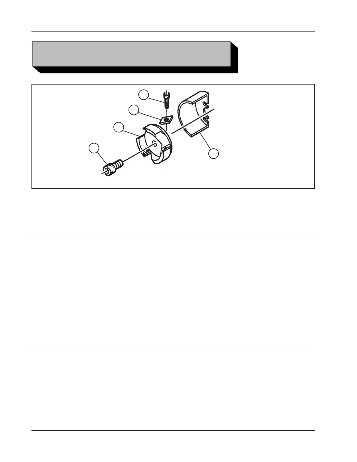
CUTTER HEAD KITS
Cutter head kit
3
2
1
5
4
#1 Cutter Head Kit, (P/N 05-0107)
Cutting Range .70" to 1.50" (17.8 mm to 38.1 mm) dia
Item Part
No. No. Description Qty
1. 21-0162 HEAD, CUTTER 1
2. 30-0784 INSERT CARBIDE 1/2” 3
3. 33-0200 SCREW, CAP, 10-32 X 1/2” 3
4. 43-0281 COVER, WELDMENT 1
5. 33-1468 SCREW, CAP, 1/4-20 X 2 3/4, LEFT HD 3
5. 33-1469 SCREW, CAP, 1/4-20 X 1 1/4, LEFT HD 3
#2 Cutter Head Kit, (P/N 05-0108)
Cutting Range 1.00" to 1.75" (25.4 mm to 44.5 mm) dia
Item Part
No. No. Description Qty
1. 21-0168 HEAD, CUTTER 1
2. 30-0784 INSERT CARBIDE 1/2” 3
3. 33-0200 SCREW, CAP, 10-32 X 1/2” 3
4. 43-0281 COVER, WELDMENT 1
5. 33-1469 SCREW, CAP, 1/4-20 X 1 1/4, LEFT HD 3
24
92-0131 : Rev. 960503
Page 25

TM
Model 103 REP
, Rapid End Prep Machine
#3 Cutter Head Kit, (P/N 05-0109)
Cutting Range 1.00" to 1.95" (25.4 mm to 49.5 mm) dia
Item Part
No. No. Description Qty
1. 21-0167 HEAD, CUTTER 1
2. 30-0785 INSERT CARBIDE 5/8” 3
3. 33-0041 SCREW, CAP, 1/4-20 X 7/8” 3
4. 43-0282 COVER, WELDMENT 1
5. 33-1469 SCREW, CAP, 1/4-20 X 1 1/4, LEFT HD 3
#4 Cutter Head Kit, (P/N 05-0110)
Cutting Range 1.25" to 2.20" (31.8 mm to 55.9 mm) dia
Item Part
No. No. Description Qty
1. 21-0166 HEAD, CUTTER 1
2. 30-0785 INSERT CARBIDE 5/8” 3
3. 33-0041 SCREW, CAP, 1/4-20 X 7/8” 3
4. 43-0282 COVER, WELDMENT 1
5. 33-1469 SCREW, CAP, 1/4-20 X 1 1/4, LEFT HD 3
#5 Cutter Head Kit, (P/N 05-0111)
Cutting Range 1.50" to 2.44" (38.1 mm to 62.0 mm) dia
Item Part
No. No. Description Qty
1. 21-0165 HEAD, CUTTER 1
2. 30-0785 INSERT CARBIDE 5/8” 3
3. 33-0041 SCREW, CAP, 1/4-20 X 7/8” 3
4. 43-0283 COVER, WELDMENT 1
5. 33-1469 SCREW, CAP, 1/4-20 X 1 1/4, LEFT HD 3
92-0131 : Rev. 960503
25
Page 26

TRI TOOL INC.
#6 Cutter Head Kit, (P/N 05-0112)
Cutting Range 1.75" to 2.70" (44.5 mm to 68.6 mm) dia
Item Part
No. No. Description Qty
1. 21-0164 HEAD, CUTTER 1
2. 30-0785 INSERT CARBIDE 5/8” 3
3. 33-0041 SCREW, CAP, 1/4-20 X 7/8” 3
4. 43-0283 COVER, WELDMENT 1
5. 33-1469 SCREW, CAP, 1/4-20 X 1 1/4, LEFT HD 3
#7 Cutter Head Kit, (P/N 05-0113)
Cutting Range 2.00" to 2.94" (50.8 mm to 74.7 mm) dia
Item Part
No. No. Description Qty
1. 21-0170 HEAD, CUTTER 1
2. 30-0785 INSERT CARBIDE 5/8” 3
3. 33-0041 SCREW, CAP, 1/4-20 X 7/8” 3
4. 43-0284 COVER, WELDMENT 1
5. 33-1469 SCREW, CAP, 1/4-20 X 1 1/4, LEFT HD 3
#8 Cutter Head Kit, (P/N 05-0114)
Cutting Range 2.25" to 3.25" (57.2 mm to 82.6 mm) dia
Item Part
No. No. Description Qty
1. 21-0163 HEAD, CUTTER 1
2. 30-0785 INSERT CARBIDE 5/8” 3
3. 33-0041 SCREW, CAP, 1/4-20 X 7/8” 3
4. 43-0284 COVER, WELDMENT 1
5. 33-1469 SCREW, CAP, 1/4-20 X 1 1/4, LEFT HD 3
26
92-0131 : Rev. 960503
Page 27

TM
Model 103 REP
, Rapid End Prep Machine
TOOL INSERTS
TOOL INSETS
Item Part
No. No. Description Qty
1. 30-0784 INSERT, TOOL 3
(FOR CUTTER HEAD KITS #1 AND #2)
2. 30-0785 INSERT, TOOL 3
(FOR CUTTER HEAD KITS #3 THROUGH #8)
92-0131 : Rev. 960503
27
Page 28

TRI TOOL INC.
TROUBLE SHOOTING
Problem: The Tool Bit Chatters
The tool bit is loose or overextended.
The tool bit is damaged.
The tool holder is too loose in the slides.
The cutting speed is too fast.
The clamping pads are loose on the pipe or tube.
Cutting fluid is required.
The main bearing pre-load is loose.
Problem: There is excessive Tool Bit wear
The pipe or tube material is too hard or abrasive.
The cutting speed is too fast.
Cutting fluid is required.
A dull Tool Bit is causing surface hardening conditions (Stainless pipe or
tubing).
There is scale or other foreign matter on the pipe or tube, which is dulling the
tool bit at the start of the cut.
The tool bit is incorrect for the material being cut.
Problem: The surface finish is rough
The tool bit is dull, chipped, etc.
Metal build-up on the cutting edge of the tool bit is creating a false cutting
edge.
Cutting fluid is required.
Problem: The tool holder is not feeding
28
The feed pin is broken or out of position.
The feed sprocket shear pin is broken.
The feed screw is stripped.
The feed nut is stripped.
The slide rails are too tight.
92-0131 : Rev. 960503
Page 29

Model 103 REP
Problem: There is a loss of air power
The air supply pressure is too low.
The air filter is plugged.
The air line size is insufficient.
The air line is too long.
Problem: There is a loss of hydraulic power
The hydraulic supply pressure is too low.
The hydraulic filter is plugged.
The hydraulic line size is insufficient.
The hydraulic line is too long.
Problem: The tool bit will not reach the work
TM
, Rapid End Prep Machine
Incorrect tool blocks are installed for the size of the pipe or tube being
worked on.
Incorrect tool bit is installed.
Problem: The hydraulic motor will not start
The hydraulic power supply is shut off.
The hydraulic motor is damaged and will not run free.
92-0131 : Rev. 960503
29
Page 30

TRI TOOL INC.
The following accessories are recommended for use with the Model 103 REP Rapid
End Prep Machine and are available from TRI TOOL INC.
1. Portable Air Caddy (P/N 75-0115)
2. Over two hundred different Pilot Mandrels. Refer to the section ‘Pilot Mandrels’.
3. Eight Cutter Head Kits. Refer to the section ‘Cutter Head Kits’.
4. Two Tool Inserts. Refer to the section ‘Cutter Head Kits’.
5. Cross Track Assy (P/N 66-0070)
ACCESSORIES
64” (1.6 m) Track Assy (P/N 66-0077)
Locator Tab (P/N 47-0360)
Weld Tab (P/N 47-0359)
6. Case, Custom Carrying (P/N 86-0075)
A Filter/Regulator/Lubricator (FRL) is required to protect the warranty on all TRI TOOL
INC air driven tools.
30
92-0131 : Rev. 960503
Page 31
TM
Model 103 REP
, Rapid End Prep Machine
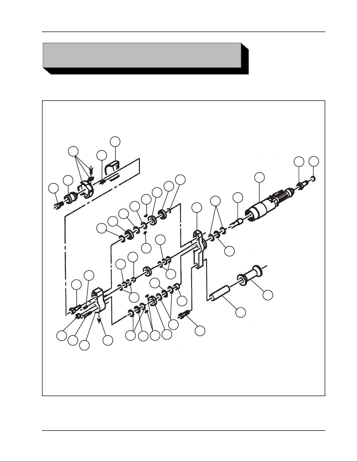
ILLUSTRATED PARTS BREAKDOWN
MODEL 103 REP RAPID END PREP MACHINE (P/N 01-1117)
1
1
20
31
32
33
15
13
25
24
21
14
21
4
8
19
5
7
29
2
1
22
23
12
28
9
10
17
6
24
11
18
3
30
21
7
27
16
26
16
7
16
92-0131 : Rev. 960503
31
Page 32

TRI TOOL INC.
Parts List, Model 103 REP Rapid End Prep Machine (P/N 01-1117)
Item Part
No. No. Description Qty
1. HEAD KIT, CUTTER
(REFER TO THE SECTION ON CUTTER HEAD KITS)
2. MANDREL, PILOT
(REFER TO THE SECTION ON PILOT MANDRELS)
3. 19-0364 HOUSING, UPPER 1
4. 19-0365 HOUSING, LOWER 1
5. 20-0318 SHAFT, DRIVE 1
6. 20-0319 SHAFT, CUTTER 1
7. 29-0107 BEARING, THRUST 3
8. 29-0188 BEARING, ROLLER, NEEDLE 1
9. 29-0189 BEARING, ROLLER, NEEDLE 1
10. 29-0190 BEARING, THRUST 2
11. 29-0191 BEARING, ROLLER, NEEDLE 1
12. 29-0193 BEARING 1
13. 29-0194 BEARING 1
14. 30-0771 RING, RETAINGIN, EXTERNAL 1
15. 30-0786 GRIP, RUBBER, BLACK 1
16. 31-0004 KEY, WOODRUFF 4
17. 32-0104 PIN, DOWEL, 5/16 DIA X 2” 1
18. 33-0044 SCREW, CAP, 1/4-20 X 1 1/2” 3
19. 33-0072 SCREW, CAP, 3/8-16 X 1 1/4” 1
20. 33-0278 SCREW, BUTTON HEAD, #10-24 X 3/8” 2
21. 34-0162 WASHER, THRUST 6
22. 34-0163 WASHER, THRUST 1
23. 34-0185 WASHER, THRUST 1
24. 34-0202 WASHER, THRUST 4
25. 39-0401 GEAR, SPUR, DRIVE 1
26. 39-0402 GEAR, SPUR, IDLER 1
27. 39-0403 GEAR, SPUR, CUTTER 1
28. 40-0156 SPRING, WAVE 1
29. 41-0062 HANDLE 1
30. 54-0375 FITTING, GREASE 1
31. 54-0126 FITTING, QUICK DISCONNECT 1
32. 54-0201 CAP, PLASTIC 1
33. 57-0121 MOTOR, AIR, INLINE 1
32
92-xxxx : Orig. or Rev. YRMTHDY
Page 33
Model No. and Name
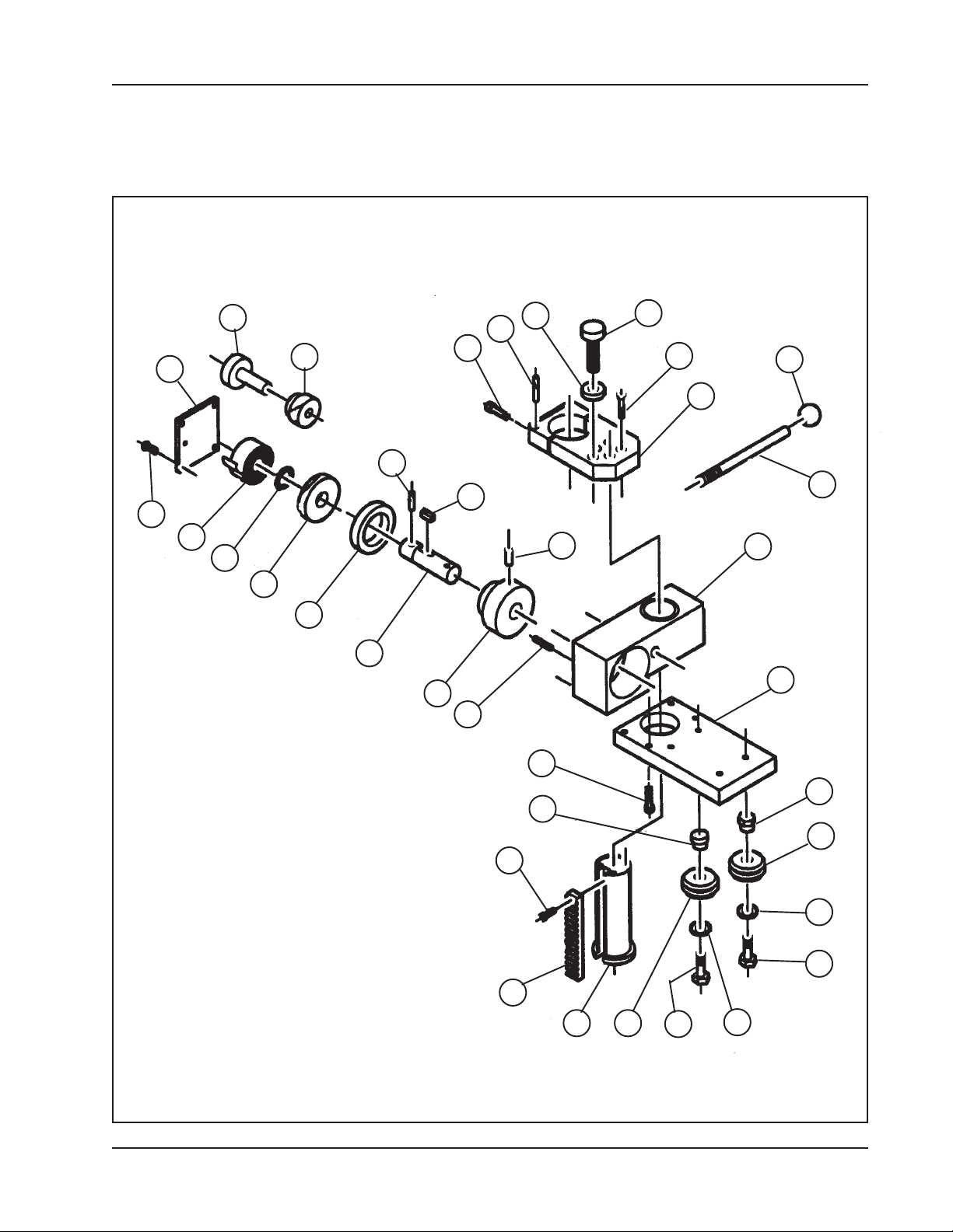
REP ADAPTOR ASSY (P/N 27-0254)
16
3
7
25
8
22
12
24
31
4
15
9
30
11
21
10
17
14
19
13
27
6
26
1
5
92-XX : Orig. or Rev. YRMTHDY
13
23
29
28
32
20
18
2
32
18
20
33
Page 34

TRI TOOL INC.
Parts List, REP Adaptor Assy (P/N 27-0254)
Item Part
No. No. Description Qty
1. 19-0379 HOUSING ASSY, GEAR 1
2. 20-0326 SHAFT, CYLINDER 1
3. 20-0327 SHAFT, GEAR 1
4. 20-0328 SHAFT ASSY, REP ADAPTOR 1
5. 24-0617 PLATE, MOUNTING 1
6. 24-0618 PLATE, CLAMPING 1
7. 24-0621 PLATE, TOP 1
8. 30-0411 RING, RETAINING, EXTERNAL 1
9. 31-0072 KEY, SQUARE 1
10. 32-0015 PIN, ROLL, 3/32 DIA X 5/16 2
11. 32-0043 PIN, ROLL, 3/16 DIA X 1 1/4” 1
12. 32-0283 PIN, GROOVED 1
13. 33-0028 SCREW, CAP, #10-24 X 1/2” 3
14. 33-0043 SCREW, CAP, 1/4-20 X 1 1/4” 8
15. 33-0057 SCREW, CAP, 5/16-18 X 1 1/4” 2
16. 33-0287 SCREW, FLAT HEAD, 1/4-20 X 3/4” 4
17. 33-1144 SCREW SET, 3/8-16 X 1”, HDOG 1
18. 33-1445 SCREW, HEX HEAD, 3/8-16 X 1 3/4” 4
19. 33-1467 SCREW, THUMB, 1/2-13 1
20. 34-0018 WASHER, FLAT 4
21. 35-0248 NUT, CHECK 1
22. 39-0153 GEAR, SPUR 1
23. 39-0428 RACK 1
24. 39-0429 GEAR, CHANGE 1
25. 40-0155 SPRING, RETURN 1
26. 41-0070 HANDLE 1
27. 42-0017 KNOB, SPHERICAL 1
28. 45-0110 BUSHING, ADJUSTABLE 2
29. 45-0111 BUSHING, STATIONARY 2
30. 45-0120 KNOB 1
31. 45-0121 BUSHING 1
32. 61-0019 JOURNAL 4
34
92-0131 : Rev. 960503
Page 35
15
TM
Model 103 REP
, Rapid End Prep Machine
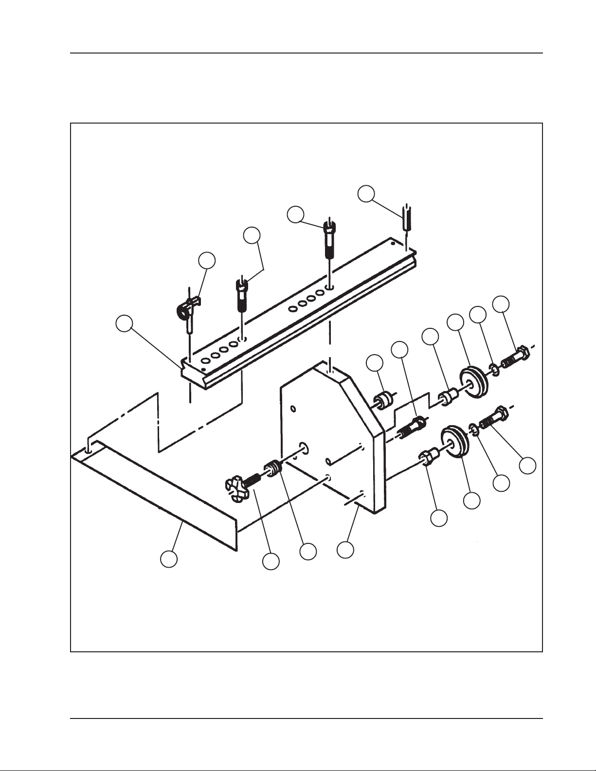
CROSS TRACK ASSY (P/N 66-0070)
6
8
7
4
7
5
13
14
9
10
2
92-0131 : Rev. 960503
11
9
10
14
12
3
1
35
Page 36

TRI TOOL INC.
Parts List, Cross Track Assy (P/N 66-0070)
Item Part
No. No. Description Qty
1. 24-0615 PLATE, BASE 1
2. 24-0616 PLATE, GUSSET 1
3. 30-0031 KEENSERT 1
4. 30-0356 PIN, LOCK 1
5. 30-0817 NUT, SWIVEL 1
6. 32-0057 PIN, ROLL, 1/4” DIA X 2” 2
7. 33-0072 SCREW, CAP, 3/8-16 X 1 1/4” 2
8. 33-0074 SCREW, CAP, 3/8-16 X 1 3/4” 2
9. 33-1445 SCREW, HEX HEAD, 3/8-16 X 1 3/4” 4
10. 34-0018 WASHER, FLAT 4
11. 42-0090 KNOB ASSY, HAND 1
12. 45-0110 BUSHING, ADJUSTABLE 2
13. 45-0111 BUSHING, STATIONARY 2
14. 61-0019 JOURNAL, DUAL VEE 4
15. 66-0068 TRACK, 23” (.6m) 1
36
92-0131 : Rev. 960503
 Loading...