

Page 1

X-SCALE / X2 CONFIGURATION MANUAL
AUTOMATED TELLER MACHINES
VERSION 5.0
TDN 07100-00016E 05/2008
CORPORATE HEADQUARTERS:
522 E. Railroad Street
Long Beach, MS 39560
Phone: (228) 868-1317
Fax: (228) 868-0437
COPYRIGHT NOTICE
© 2007-2008 Delaware Capital Formation, Inc. All Rights Reserved. Triton Systems of Delaware
Inc. is an operating company of Dover Electronics, Inc., a subsidiary of Dover Corporation
(DOV -NYSE). DOVER, the DOVER logo and the Dover family of marks and TRITON, the TRIT ON
logo and the Triton family of marks are registered trademarks of Delaware Capital Formation,
Inc., a wholly owned subsidiary of Dover Corporation.
Page 2

X-SCALE / X2 CONFIGURATION MANUAL
NOTICES
Copyright © Delaware Capital Formation, Inc., 2007-2008.
LL RIGHTS RESERVED
A
This publication is protected by copyright and all rights are reserved. No part of it may be reproduced or
transmitted by any means or in any form, without prior consent in writing from Triton Systems of Delaware, Inc.
The information in this publication has been carefully checked and is believed to be accurate. However,
Triton Systems of Delaware, Inc. assumes no responsibility for any inaccuracies, errors, or omissions
that may be contained in this document. In no event will Triton Systems of Delaware, Inc. be liable for
direct, indirect, special, incidental, or consequential damages resulting from any defect or omission in this
manual, even if advised of the possibility of such damages.
In the interest of continued product development, Triton Systems of Delaware, Inc. reserves the right to
make improvements in its documentation and the products it describes at any time, without notice or
obligation.
T
RADEMARK ACKNOWLEDGEMENTS
Microsoft W indows is a registered trademark of Microsoft Corporation in the United States and/or other
countries. Triton Connect is a trademark of Triton Systems of Delaware, Inc. VISA® is a registered
trademark of VISA of the United States and other countries.
ii
Page 3

MANAGEMENT FUNCTIONS
CONTENTS
BASIC OPERATION .................................................................................... 1
CONTROL PANEL LAYOUT ........................................................................................................................2
F
UNCTION KEYS .....................................................................................................................................2
MAIN KEYPAD .......................................................................................................................................3
O
N-SCREEN KEYPAD OPERATIONS............................................................................................................3
ENU-BASED OPERATIONS .....................................................................................................................4
M
ACCESSING MANAGEMENT FUNCTIONS .....................................................................................................5
CHANGING DEFAUL T PASSWORD (EC 246)...............................................................................................5-6
X2 L
OAD FILES ......................................................................................................................................7
FUNCTIONS AVAILABILITY ........................................................................................................................8
ANAGEMENT REPORTS ..........................................................................................................................9
M
R
EQUIRED PARAMETERS ..........................................................................................................................9
REAR SERVICE PANELS AND MENU OPTIONS .............................................................................................10
OPTION 1 - TERMINAL CLOSE FUNCTIONS ................................................. 11
TERMINAL CLOSE FUNCTIONS ..................................................................................................................12
TERMINAL CLOSE FUNCTIONS MENU OPTIONS OVERVIEW ..........................................................................13
SCHEDULE CLOSE ..................................................................................................................................14
S
END TERMINAL TOTALS ........................................................................................................................15
T
RIAL CLOSE / DAY CLOSE.....................................................................................................................16
TRIAL CASSETTE CLOSE .........................................................................................................................17
ASSETTE CLOSE ...................................................................................................................................18,19
C
OPTION 2 - DIAGNOSTICS ......................................................................... 21
DIAGNOSTICS FUNCTIONS .........................................................................................................................22,23
DIAGNOSTICS MENU OPTIONS OVER VIEW ..................................................................................................24,25
TERMINAL STATUS .................................................................................................................................26
CURRENT TERMINAL ERROR / ERROR HISTORY .........................................................................................27
RESET TERMINAL ERROR / CONFIGURATION SUMMARY .............................................................................28
R
ESTORE DEFAUL T PARAMETERS .............................................................................................................29
S
AVE / RESTORE PARAMETERS USING AN EXTERNAL STORAGE DEVICE .......................................................30
TRANSACTION TOTALS / SYSTEM DIAGNOSTICS .......................................................................................31
DISPENSER .............................................................................................................................................32
CASH DISPENSER STATUS / PURGE ..........................................................................................................33
TEST DISPENSE / SHUTTER TEST (FT5000) ..............................................................................................34
INJECT NEW CASSETTE ID ......................................................................................................................3 5
F
ORCE UNLOCK CASSETTE .....................................................................................................................36
DISPENSER TOTALS / RESET DISPENSER ...................................................................................................37
C
ASSETTE PARAMETERS .........................................................................................................................38,39
iii
Page 4

X-SCALE / X2 CONFIGURATION MANUAL
CONTENTS
C
ARD READER .......................................................................................................................................40
ARD READER STATUS / TOTALS .............................................................................................................40
C
S
CAN CARD ..........................................................................................................................................41
RINTER................................................................................................................................................42
P
D
EVICE STA TUS .....................................................................................................................................42
RESET/TEST PRINTER / CONFIGURE PRINTER ............................................................................................43
M
ODEM/ETHERNET .................................................................................................................................44
EVICE STATUS / TEST ...........................................................................................................................45
D
ODEM TOTALS ...................................................................................................................................46
M
C
ONFIGURE MODEM / TRITON CONNECT SETTINGS ...................................................................................47,48
CONFIGURE ETHERNET SETTINGS ............................................................................................................49,50
MODEM SETUP STRING ..........................................................................................................................51
KEYP AD ..................................................................................................................................................52
D
EVICE STATUS / TEST / CLEAR SERIAL#_TAMPER ERRORS ......................................................................52
GENERAL I/O DIAGNOSTICS ...................................................................................................................53
LED INDICATORS / AUDIO OUTPUT / HEADPHONE INTERRUPTS ..................................................................53
CONFIGURE LED FLASH RATE / CONFIGURE LED BRIGHTNESS (RL2000)
TCP/IP W
IRELESS (IF USED) ..................................................................................................................54
OPTION 3 - ELECTRONIC JOURNAL ............................................................ 55
ELECTRONIC JOURNAL FUNCTIONS ............................................................................................................56
ELECTRONIC JOURNAL MENU OPTIONS OVERVIEW .....................................................................................57
DISPLAY UNAUDITED RECORDS ................................................................................................................58
DISPLAY LAST X ....................................................................................................................................59
D
ISPLA Y SELECTED RECORDS..................................................................................................................60-61
LEAR JOURNAL ...................................................................................................................................62
C
A
RCHIVE / DELETE JOURNAL .................................................................................................................63
VIEW JOURNAL ARCHIVE .......................................................................................................................64
JOURNAL PROPERTIES ...........................................................................................................................65
AUTO ARCHIVE ......................................................................................................................................66-67
OPTION 4 - PASSWORD MAINTENANCE ...................................................... 69
PASSWORD MAINTENANCE FUNCTIONS .....................................................................................................70
PASSWORD MAINTENANCE MENU OPTIONS OVERVIEW ..............................................................................71
CHANGE USER PASSWORD / USER NAME .................................................................................................72
ODIFY USER ACCESS ............................................................................................................................73-74
M
ADD USER / REMOVE USER ......................................................................................................................75
TERMINAL USERS / USER ACCESS REPORT ...............................................................................................76
iv
Page 5

MANAGEMENT FUNCTIONS
CONTENTS
OPTION 5 - SYSTEM PARAMETERS ............................................................. 77
SYSTEM PARAMETERS FUNCTIONS .............................................................................................................78
S
YSTEM PARAMETERS MENU OPTIONS OVERVIEW ......................................................................................79
DATE AND TIME .....................................................................................................................................80-81
A
DVANCED SETTINGS (REGIONAL SETTINGS / REGIONAL AND LANGUAGE SETTINGS ...............................82
ET REGION ..........................................................................................................................................84
S
SET NUMBERS .......................................................................................................................................85-86
SET CURRENCY .....................................................................................................................................87-88
S
ET TIME / SET DATE ............................................................................................................................89-90
VOLUME CONTROL .................................................................................................................................90
HUTDOWN / RESTART TERMINAL...........................................................................................................91
S
S
ELECT SCREEN FILE ............................................................................................................................92
SOFTWARE UPDATE ................................................................................................................................. 93-94
STATISTICS ............................................................................................................................................95
S
CHEDULE REBOOT................................................................................................................................96
OPTION 6 - TERMINAL CONFIGURATION...................................................... 97
TERMINAL CONFIGURATION FUNCTIONS ....................................................................................................98-101
T
ERMINAL CONFIGURATION MENU OPTIONS OVERVIEW ..............................................................................102
GENERAL PARAMETERS .................................................................................................................................. 103-105
T
ERMINAL ID .......................................................................................................................................103
IP CODE .............................................................................................................................................104
Z
R
ESET SEQUENCE NUMBER ....................................................................................................................104
EFAULT LANGUAGE .............................................................................................................................104
D
D
EFAULT TRANSACTION TYPE ................................................................................................................104
DEFAULT ACCOUNT TYPE ......................................................................................................................104
O
UT OF SERVICE ON LOW PAPER ............................................................................................................104
OUT OF SERVICE ON PRINTER ERROR .......................................................................................................105
STATUS MONITORING .............................................................................................................................105
EARTBEAT MESSAGE ...........................................................................................................................105
H
H
EARTBEAT DELAY PERIOD ....................................................................................................................105
COUPONS ......................................................................................................................................................... 106-108
C
OUPON ...............................................................................................................................................106
PROMPT................................................................................................................................................106
MIN. LEVEL (WITHDRAWAL AMOUNT) ....................................................................................................107
AX. LEVEL (WITHDRAWAL AMOUNT) ...................................................................................................107
M
R
ANDOM ..............................................................................................................................................107
A
WARD BASED ON ISO PROPERTIES .......................................................................................................107
v
Page 6

X-SCALE / X2 CONFIGURATION MANUAL
CONTENTS
MESSAGE .............................................................................................................................................107
AYOUT (PRINTER ) ................................................................................................................................ 107
L
GRAPHIC (PRINTER) ............................................................................................................................... 108
RINT (PRINTER)....................................................................................................................................108
P
C
ASSETTE (DISPENSED)..........................................................................................................................108
COUNT (DISPENSED)..............................................................................................................................108
T
ERMINAL MESSAGES ............................................................................................................................109
ELCOME MESSAGE ............................................................................................................................109
W
TORE MESSAGE ...................................................................................................................................110
S
M
ARKETING MESSAGE ..........................................................................................................................110
EXIT MESSAGE ......................................................................................................................................110
TERMINAL OWNER ................................................................................................................................ 110
SURCHARGE MESSAGE ..........................................................................................................................110
CASSETTE SETUP....................................................................................................................................111
MAXIMUM AMOUNT ..............................................................................................................................111
M
AXIMUM NON-CASH ...........................................................................................................................112
MIX METHOD .......................................................................................................................................112
FAST CASH ...........................................................................................................................................112
CASSETTE PARAMETERS .......................................................................................................................113
RELEARN BILL THICKNESS .....................................................................................................................113
LL CASSETTES LOCKED/UNLOCKED......................................................................................................114
A
R
ETRACT CASH .....................................................................................................................................114
ENABLE EXTENSION REJECTS ..................................................................................................................114
A
CTIVE CASSETTE ................................................................................................................................. 114
CASSETTE IN SERVICE ............................................................................................................................114
ULTIPLE AMOUNT ..............................................................................................................................115
M
OCUMENT TYPE ..................................................................................................................................115
D
N
ON-CASH ITEM DESCRIPTION ...............................................................................................................115
SECONDARY ITEM DESCRIPTION ..............................................................................................................115
NOTE CONFIGURATION .........................................................................................................................116
BILL WIDTH .........................................................................................................................................116
BILL LENGTH ........................................................................................................................................116
ALUE .................................................................................................................................................116
V
V
ARIANT ..............................................................................................................................................117
CODE ...................................................................................................................................................117
ISO / SURCHARGE PROPERTIES .............................................................................................................118
ENABLE / DISABLE SURCHARGE .............................................................................................................118
AMOUNT ..............................................................................................................................................118
PERCENT ..............................................................................................................................................119
vi
Page 7

MANAGEMENT FUNCTIONS
CONTENTS
USE WHICHEVER IS LESSER/GREATER .......................................................................................................119
LLOW ONLY ISOS LISTED BELOW AS “ACCEPT” ....................................................................................120
A
A
DD NEW ............................................................................................................................................120
ELETE ................................................................................................................................................120
D
DIT .....................................................................................................................................................120
E
COMMUNICATION ...................................................................................................................................121
P
RIMARY PHONE # / HOST IP ADDRESS...................................................................................................122
ACKUP PHONE # / HOST IP PORT ..........................................................................................................122
B
REDIAL / PERMANENT TCP/IP CONNECTION ..........................................................................................122
P
E
NABLE COMMUNICATION HEADER .........................................................................................................123
USE 12-DIGIT SEQUENCE NUMBER .........................................................................................................123
AMOUNT TYPE .....................................................................................................................................123
C
OMMUNICATION PROTOCOL ..................................................................................................................124
COMMUNICATION MESSAGE FORMAT .......................................................................................................124
NUA NUMBER / HOST RESPONSE TIMEOUT .............................................................................................124
ENABLE PERSISTENT REVERSALS .............................................................................................................124
ENABLE REVERSALS FOR PROTOCOL ERRORS ............................................................................................125
ADS GRAPHICS .......................................................................................................................................126
A
DD NEW ............................................................................................................................................127-129
DELETE / EDIT ......................................................................................................................................130
OVE UP/DOWN ..................................................................................................................................131
M
G
RAPHIC EXAMPLES ..............................................................................................................................132
OPTIONAL SCREENS ...............................................................................................................................133
A
CCOUNT / TRANSACTION .....................................................................................................................133
LANGUAGE SELECTION ..........................................................................................................................134
URCHARGE MESSAGE ..........................................................................................................................134
S
ECEIPT OPTION ...................................................................................................................................134
R
O
PTIONAL SCREEN BUTTONS .................................................................................................................135
CCOUNT / TRANSACTION .....................................................................................................................135
A
F
AST CASH AMOUNTS ............................................................................................................................136
PURCHASE SELECTIONS ..........................................................................................................................136
ENABLING / DISABLING OPTIONAL SCREEN BUTTONS ...............................................................................136
REVIEWING OPTIONAL SCREEN BUTTON CONFIGURATION ........................................................................136
P
TRITON CONNECT ..................................................................................................................................137
PRIMARY PHONE # / HOST IP ADDRESS ...................................................................................................138
B
ACKUP PHONE # / HOST IP PORT ..........................................................................................................138
ALARM MONITOR (PRIMARY) / A LARM IP ADDRESS ................................................................................138
ALARM MONITOR (BACKUP) / ALARM IP PORT .......................................................................................139
MAX RETRIES .......................................................................................................................................139
vii
Page 8

X-SCALE / X2 CONFIGURATION MANUAL
CONTENTS
R
EDIAL DELAY .......................................................................................................................................140
NABLE TRITON CONNECT .....................................................................................................................140
E
E
NABLE CALL BACK .............................................................................................................................140
NABLE SCHEDULED JOURNAL CALLS ....................................................................................................140
E
ALL AT NUMBER OF JOURNAL RECORDS ................................................................................................141
C
C
ALL AT LOW CASH THRESHOLD ............................................................................................................141
ENTER NEW ACCESS CODE.....................................................................................................................141
EMV C
ONFIGURATION ...........................................................................................................................142
EMV P
ROCESSING .................................................................................................................................142
EMV APPLICATION SETTINGS .................................................................................................................142
ICC LA TCHING ......................................................................................................................................143
NON-ICC TRANSACTIONS ......................................................................................................................143
ALLBACK TO MAGNETIC STRIPES ...................................................................................................143
ICC F
T
ERMINAL EMV CONFIGURATION ...........................................................................................................143
LAST TRANSACTION’S EMV DATA ..........................................................................................................143
OPTION 7 - KEY MANAGEMENT ................................................................. 145
KEY MANAGEMENT FUNCTIONS ...............................................................................................................146
K
EY MANAGEMENT MENU OPTIONS OVERVIEW ........................................................................................147
ENTER MASTER KEYS .............................................................................................................................148
CHANGE PASSWORDS ..............................................................................................................................149
ENTER MAC MASTER KEYS ....................................................................................................................150-151
ENTER PIN MASTER KEYS .......................................................................................................................152-153
DOWNLOAD WORKING KEYS ..................................................................................................................154
C
HECK DIGITS.......................................................................................................................................155
OPTION 8 - TERMINAL STATUS .................................................................. 157
TERMINAL STATUS FUNCTIONS ..................................................................................................................158
TERMINAL STATUS MENU OPTIONS OVERVIEW...........................................................................................159
CURRENT TERMINAL ERROR / TERMINAL ERROR HISTORY ......................................................................160
R
ESET TERMINAL ERROR / CONFIGURATION SUMMARY ...........................................................................161
R
ESTORE DEFAULT PARAMETERS ............................................................................................................162
SAVE / RESTORE PARAMETERS TO/FROM EXTERNAL STORAGE .................................................................163
OPTION 9 - LANGUAGE.............................................................................. 165
viii
Page 9

MANAGEMENT FUNCTIONS
CONTENTS
APPENDIX A - SOFTWARE LICENSE AGREEMENT ........................................... A-1
PPENDIX B - TERMINAL ERROR CODES.................................................... B-1
A
UPPLEMENTS (SOFTWARE RELEASE NOTES - COUNTRY(S) SPECIFIC)
S
UPPLEMENT A - X-SCALE (RL/FT5000, RT2000)
S
UPPLEMENT B - X2 (RL2000, RL/FT5000X2, RT2000X2)
S
UPPLEMENT C - KEY MANAGEMENT PROCEDURES (T5/T7 PCI-EPPS)
S
ix
Page 10

X-SCALE / X2 CONFIGURATION MANUAL
THIS PAGE INTENTIONALLY LEFT BLANK
x
Page 11

BASIC OPERATION
1
Page 12
X-SCALE / X2 CONFIGURATION MANUAL
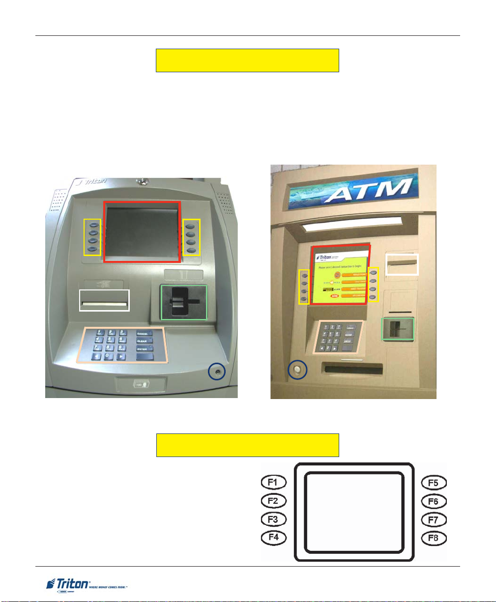
CONTROL PANEL LAYOUT
The user interface of the terminal consists of the LCD screen, receipt chute, card reader, speaker , headphone
jack (visually impaired), and 24 keys on three keypads. The Function keys are arranged in two four-key
groups, one group on either side of the LCD display. The main keypad consists of 10 alphanumeric keys,
two arrow keys and four large control keys, all located in a 16-key group beneath the LCD screen.
The main keypad and control keys have an integral raised Braille symbol to conform to the requirements of
the Americans with Disabilities Act.
Lobby unit (example)
FUNCTION KEYS
The eight (8) keys, arranged in two four-key groups,
are called screen function keys. A screen function
key is only active when a corresponding function or
menu option is present next to that key. The Function keys are designated F1 through F8.
Through-the-wall unit (example)
2
Page 13
BASIC OPERATION
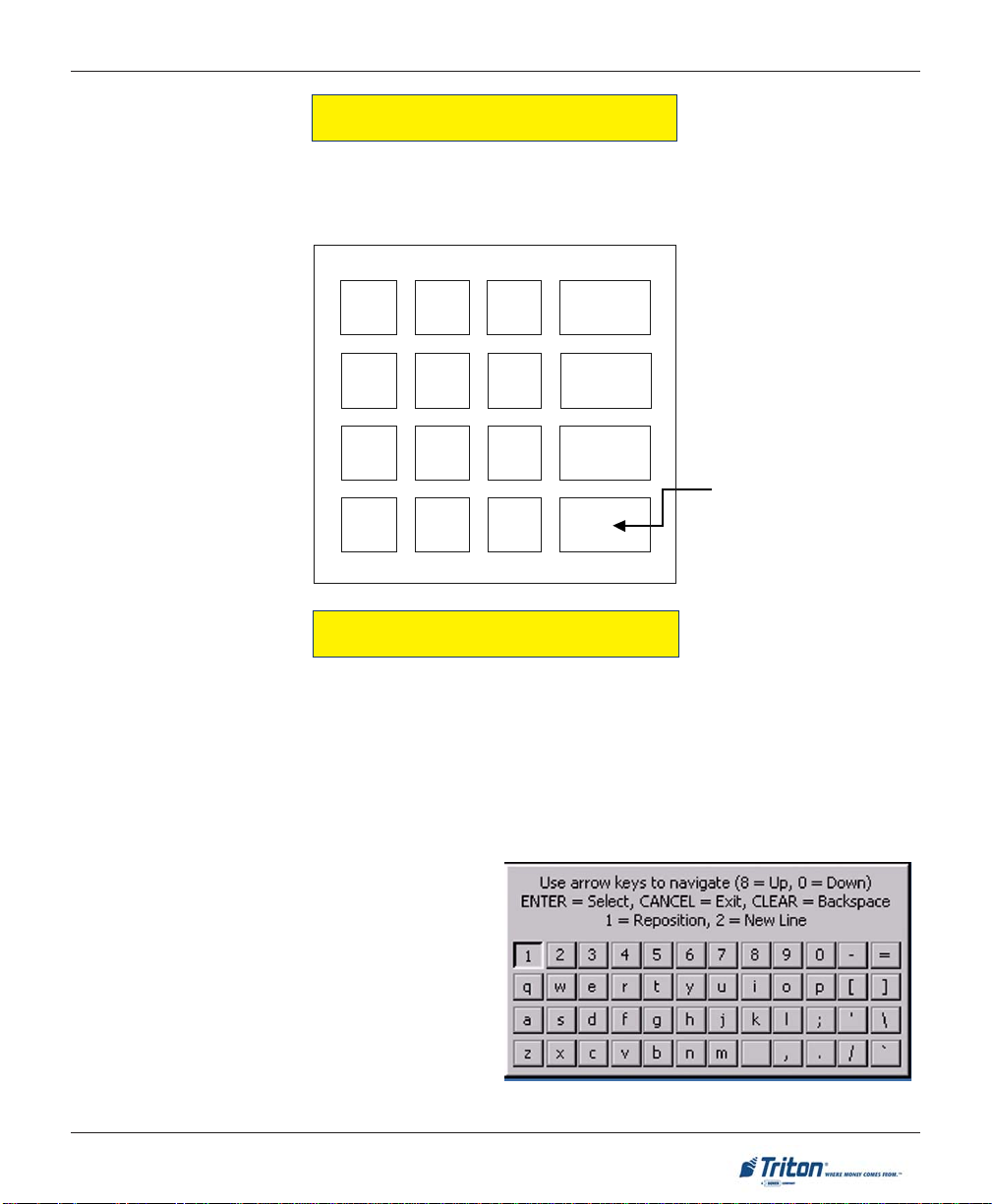
MAIN KEYPAD
The entry of numeric characters via the main keypad is straightforward: simply press the desired key.
However, in certain Management Function screens it may be necessary to enter alphabetic characters, a
procedure that’s available with the On-Screen keypad.
1
QZ2ABC3DEF
4
GHI5JKL6MNO
7
PRS8TUV9WXY
CANCEL
CLEAR
O
ENTER
x
<
CTRL
0
<>
ON-SCREEN KEYPAD OPERATION
To enter text characters into the dialog boxes that are displayed by the Management Functions, press the
F8 key to display the screen keyboard. Use the keys described below to navigate and enter required data.
• The Arrow keys (< AND >), the <8> key - (UP), and the <0> key - (DOWN) navigate the keyboard.
• Press the <E
• Press the <CTRL> key to switch between upper and lower case characters.
NTER> key to select the highlighted key entry.
• Press the <CANCEL> key to Exit the keyboard.
• Press the <C
tion.
• Press the <1> key to reposition the keyboard to
another location on the display.
• Press the <2> key to positon the cursor on a new
line.
LEAR> key for the Backspace opera-
3
Page 14
X-SCALE / X2 CONFIGURATION MANUAL
MENU-BASED OPERATION
The terminal operates as a menu driven system. Messages and menu options presented on the LCD display
screen guide the user’s actions. The desired menu option is selected by pressing one of the keys located to
the left and right of the display . For the purpose of security many screens timeout after a preset time interval,
usually 30 seconds. The timeout length may vary depending on the function being performed.
When a screen timeout occurs, a screen is presented which asks the user if more time is needed. If the user
chooses NO, the Customer Welcome screen will be presented. If YES is chosen, the user is returned to the
function that was active prior to the timeout. If the user does not make a selection within an additional 30second countdown period the terminal will automatically go to the Customer Welcome screen.
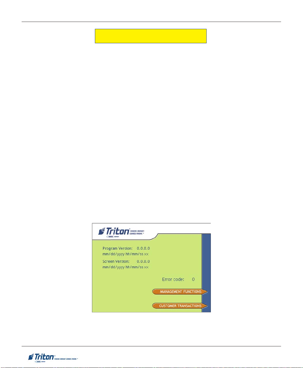
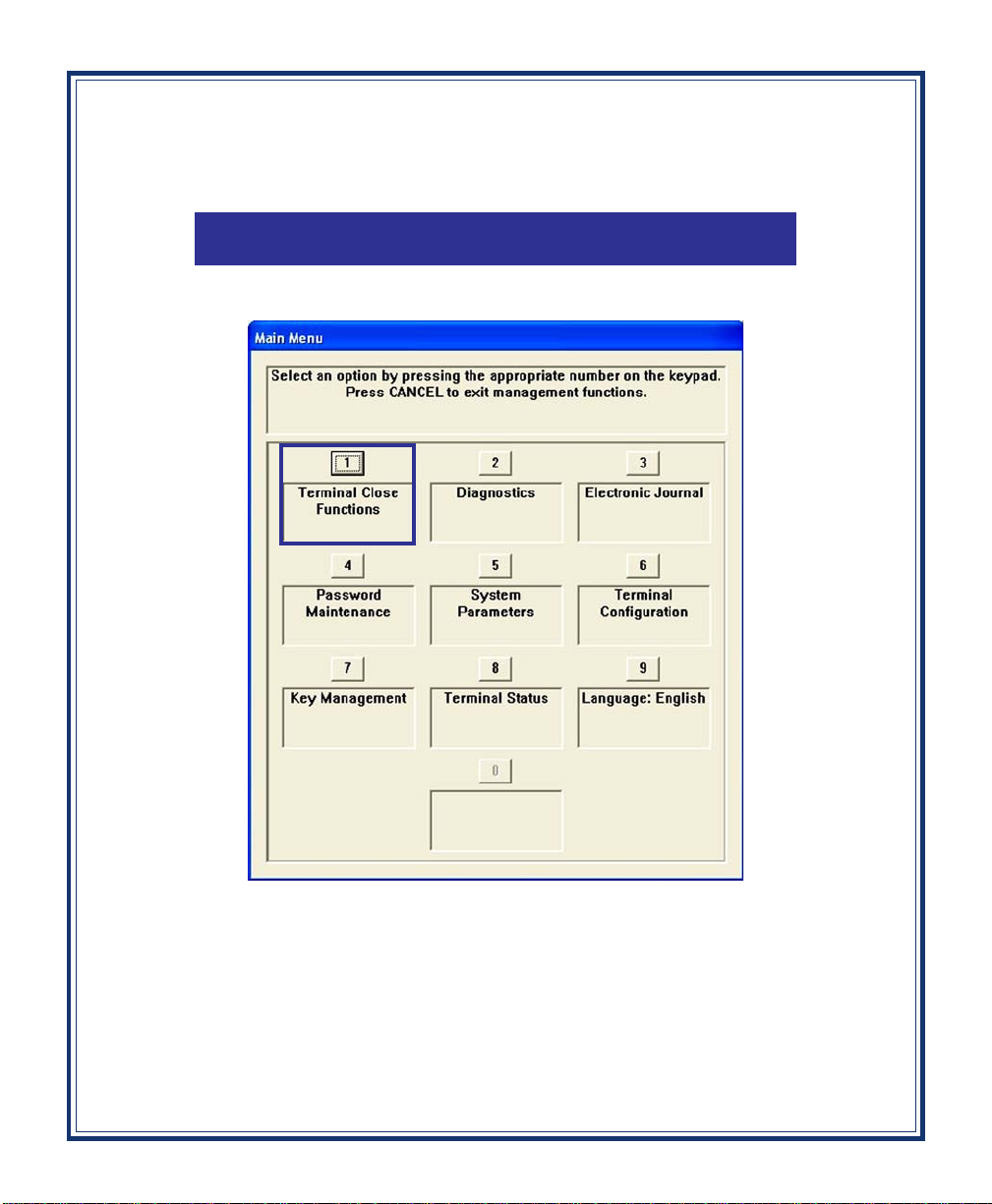
Shortly after the unit is turned on, the top menu will be displayed. An example top menu is shown below.
From the top menu, you can either:
1. Activate the terminal to perform customer transactions by pressing the key next to CUSTOMER
TRANSACTIONS.
2. Enter the terminal system management area by pressing the key next to MANAGEMENT FUNCTIONS.
Note: You will have to enter an appropriate password to view the Management Functions menu.
If you do not select a menu choice within 30 seconds the terminal will automatically default to the Customer
Welcome screen (a benefit of this feature is that in the event of a power interruption the terminal will
automatically begin accepting customer transactions shortly after power is restored).
4
Page 15
BASIC OPERATION
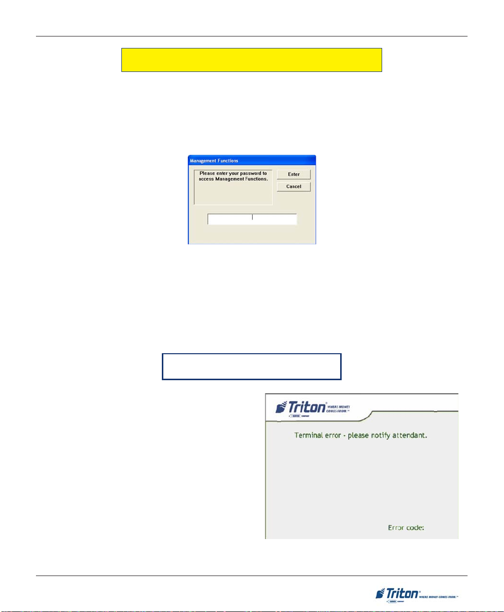
ACCESSING THE MANAGEMENT FUNCTIONS MENU
After initial setup, when the Customer Welcome screen is displayed, you can access the Management
Functions menu by following the procedure described next.
Press and hold down the blank <CTRL> key; while holding down the <CTRL> key, press the <1> key .
Release both keys. After a moment the “Security Login” screen will be displayed.
You must enter an appropriate password in the dialog box that appears when the Management Functions
option is selected. The password will consist of a 2-digit ID code and a password of 4-12 digits; for example,
051234 could be a password entry consisting of an ID code of 05 and a password of 1234.
Enter your password and press <ENTER>.
When a valid login is entered, the Main Menu screen will be displayed.
CHANGING DEFAULT PASSWORDS
With the release of newer software, you will experience a new error code. Error Code (246) has
been created for when the terminal’s Master Password is in its default state. The terminal will detect this condition and go out of service. On the
“Out of Service” screen, no error information will
be displayed. The following is a screen capture of
this state. This error code will not clear until the
Master Password is changed from its default state.
Follow the steps on the next page for changing
default password and clearing error.
246
5
Page 16
X-SCALE / X2 CONFIGURATION MANUAL
CHANGING DEFAULT PASSWORDS
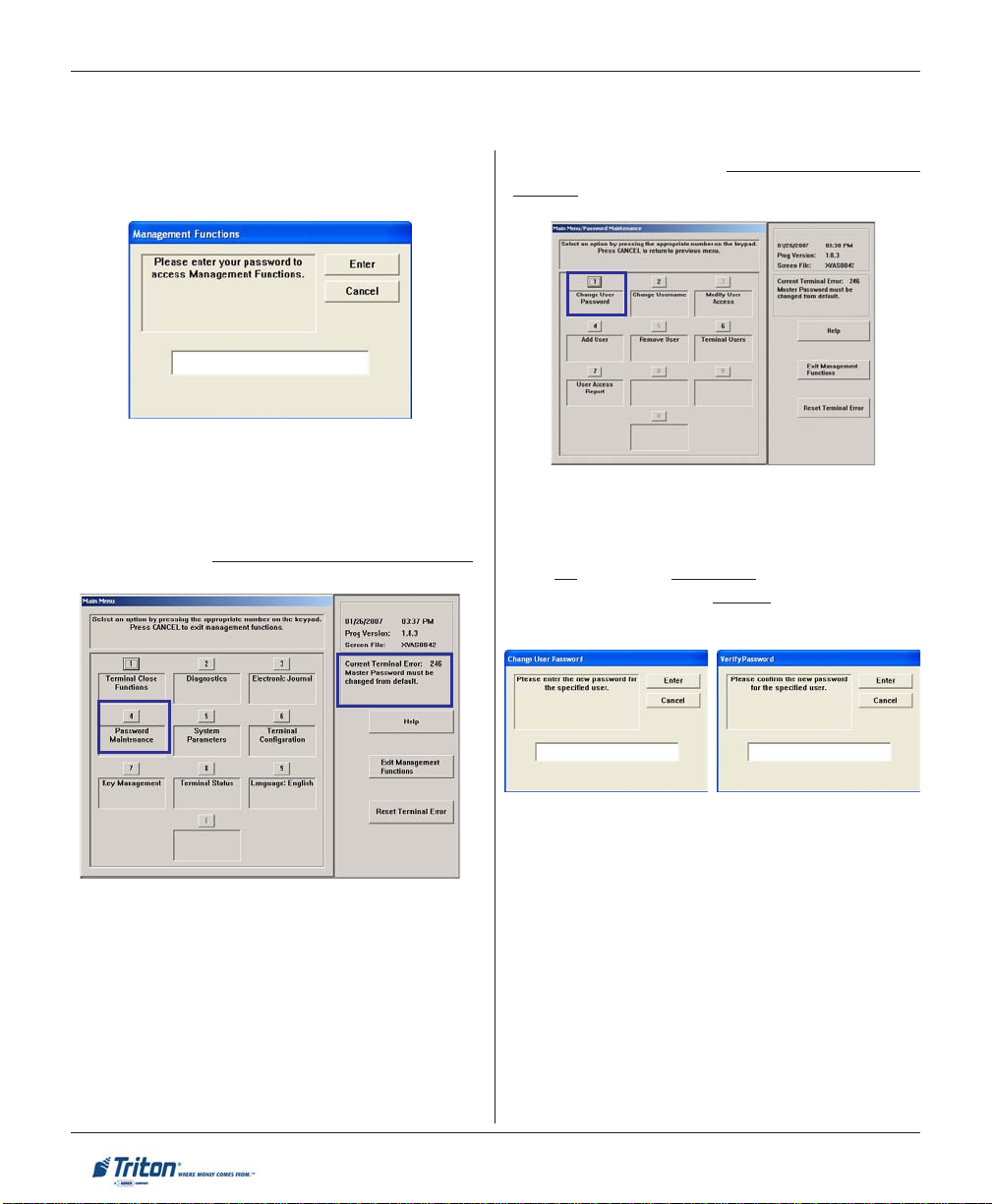
1. Enter Management Functions <CTRL> and
<1>. Enter the default password ‘001234’.
2. The Main Menu appears. Error code ‘246’
appears at right and its description “Master password must be changed from default”.
Select option <4>, PASSWORD MAINTENANCE.
3. Select option <1>, CHANGE USER PASS-
WORD.
4. Enter a new Master password.
NOTE: The terminal password consists of a 2digit
ID code and a Password of 4-12 digits. ‘00’ is
the Master ID code and cannot be changed. Only
enter the password digits!
Example: If you enter ‘5566’, then the Master password will be changed to ‘005566’. If you enter
‘005566’, then the Master password will be
changed to ‘00005566’.
NOTE: You will prompted to “Reconfirm” the
new password.
5. Exit out of Management Functions. The
terminal Master password has changed.
6
Page 17
BASIC OPERATION
X2 LOAD FILES
Country specific settings will be loaded via a parameter file for each country. This setting will drive specific
spellings, screen flows, etc. that may be unique to a market or country.
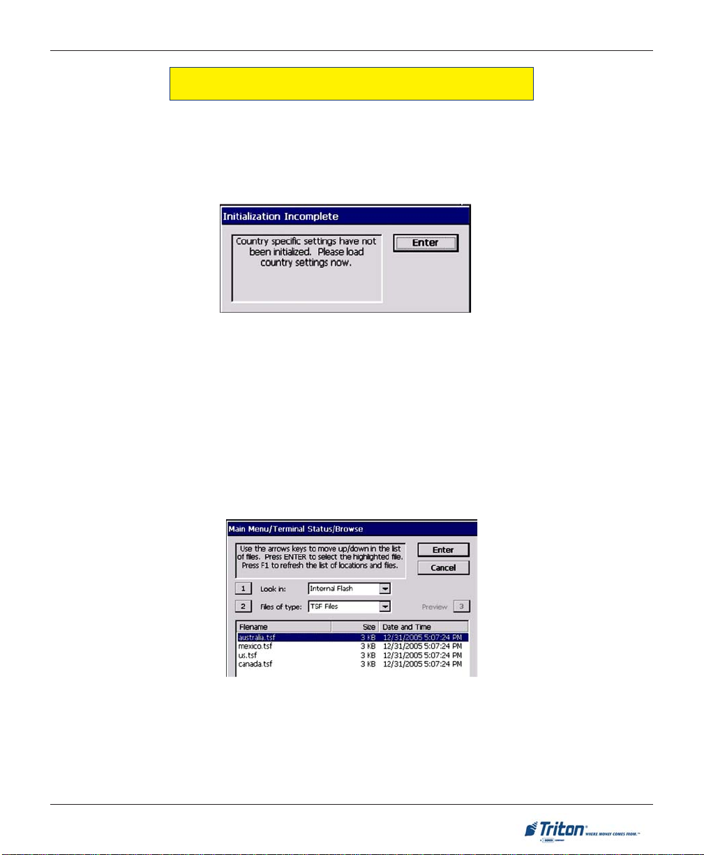
After the initial installation of a full-load file, upon entering management functions the ‘Initialization Incomplete’ dialog will be displayed:
At this point the only option is to press <E
more country-specific parameter files exist on the terminal:
1. If no country-specific parameter file exists, the terminal’s built-in defaults will be loaded and you
will be returned to the Management Functions Main Menu.
2. If a single country-specific parameter file exists, the country-specific default parameters will be
loaded from this file and you will be returned to the Management Functions\terminal Status Main Menu.
3. If more than one parameter file exists, a browse dialog will appear, allowing you to select the
applicable parameter file. Selecting a file and pressing “Enter” will load the country-specific default parameters from this file and return you to the Management Functions\Terminal Status Main Menu. Here is an
example of the browse dialog:
IMPORTANT: If the browse dialog is displayed it is possible to abort loading of a country-specific parameter
file by pressing ‘Cancel.’ In this case you will still need to return to the dialog later and select a parameter file
to ensure all country-specific defaults have been initialized. To return to the browse dialog, select the
Terminal S tatus option from the Management Functions Main menu and press the ‘Restore Default Parameters’ option. Until a parameter file has been loaded you will continue to be prompted by the ‘Initialization
Incomplete’ dialog whenever entering Management Functions.
NTER>. What happens next will depend upon whether one or
7
Page 18
X-SCALE / X2 CONFIGURATION MANUAL
* Note *
The availability of some Management Functions will depend on such
factors as dispenser type, optional
hardware installed, user password
options, etc. In cases where a function is not applicable or available, the
option will be “grayed out” or otherwise disabled.
FUNCTION AVAILABILITY
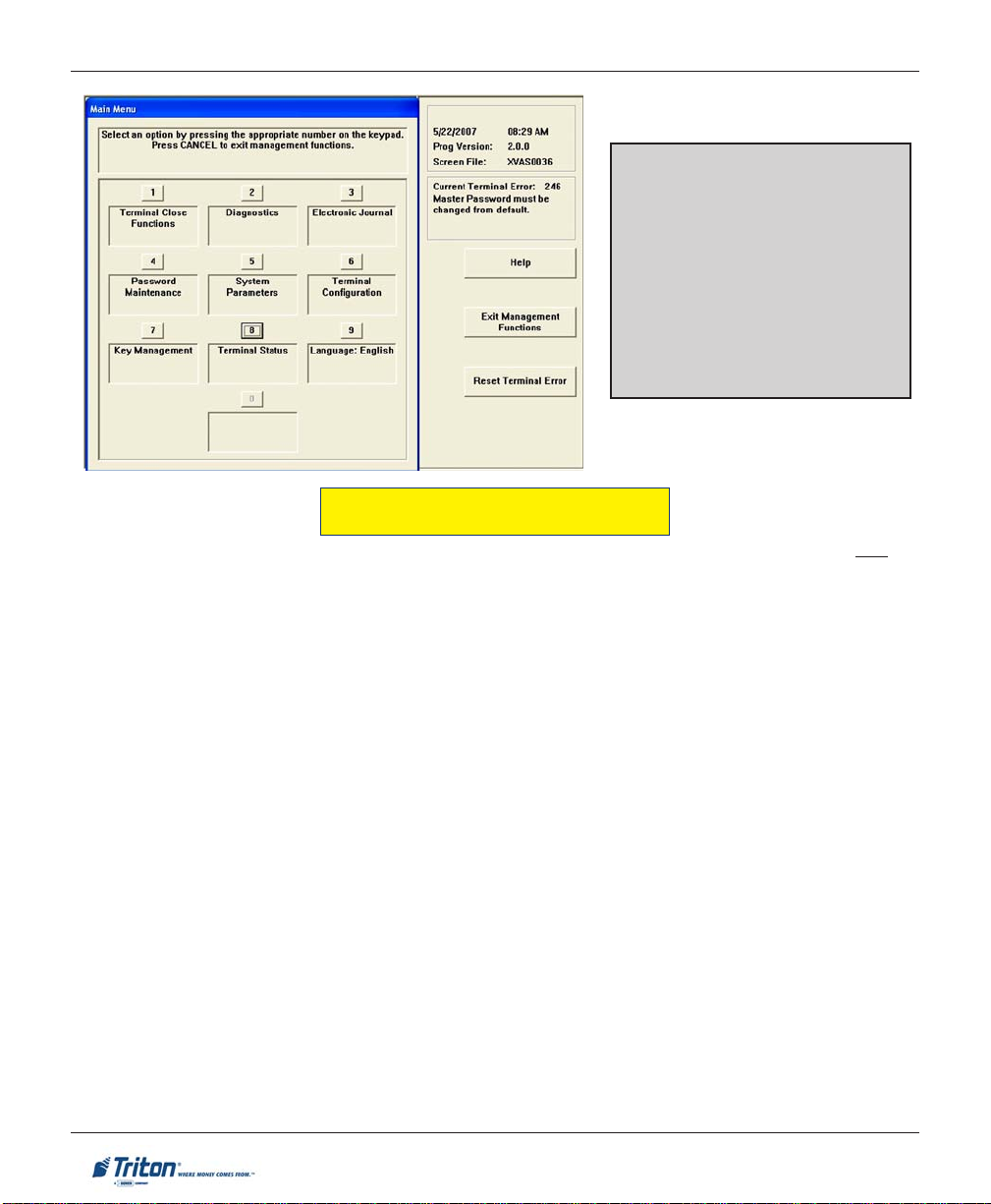
Once you have entered the Main Menu, you may perform any of the functions allowed by the type of
password used (access level).
The Main Menu screen allows the service provider/terminal operator to access the following Management
functions (determined by password access level):
1. CLOSE FUNCTIONS. Used to perform cassette close, day close, and schedules close functions.
2. DIAGNOSTICS. Used to perform terminal hardware testing and to view test results.
3. E
LECTRONIC JOURNAL. Used to manage the ATM’s journal functions, such as display/print, archive,
and delete.
ASSWORD MAINTENANCE. Used to add/delete users and modify terminal access privileges.
4. P
5. S
YSTEM PARAMETERS. Used to shut down or restart the terminal, update terminal software, and set
terminal date/time settings.
6. T
ERMINAL CONFIGURATION. Used to view/edit terminal operating parameters such as terminal ID,
surcharging, status monitoring, cash dispenser setup, ads/graphics, communication setup, and Triton
Connect configuration.
EY MANAGEMENT. Used to enter encryption keys, which protect communications between the A TM
7. K
and the transaction processing service provider.
8. TERMINAL STATUS. Used to view terminal status reports (error history ,configuration summary), save
and restore parameters, and reset terminal errors.
ANGUAGE. Press this option repeatedly to cycle through the available languages. The current
9. L
language displayed is used for all management function screens.
8
Page 19
BASIC OPERATION
MANAGEMENT REPORTS
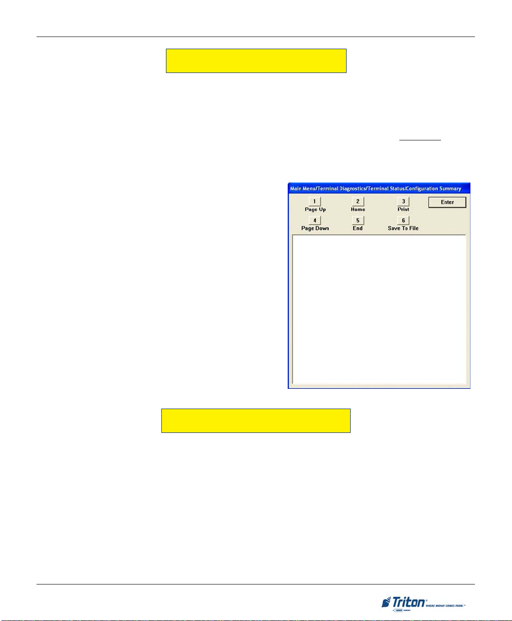
Many Management Functions, such as Close, Journal, and Diagnostic functions, produce a report summarizing the results of the operation. Most reports are displayed in a Management Report dialog, which you
can use to print the report to the receipt printer or save to an external memory device (USB jumpdrive).
Note: If saving to an external memory device, the device must be installed (USB port) BEFORE saving
to that device.
The buttons on the Management Report dialog let you perform the following actions:
AGE UP. Scrolls the report up a maximum of
1. P
one full page.
OME. Moves directly to the first page of the
2. H
report.
3. PRINT. Sends the report to the terminal receipt
printer for hardcopy output.
AGE DOWN. Scrolls the report down a maxi-
4. P
mum one full page.
5. E
ND. Moves directly to the last page of the
report.
AVE TO FILE. Saves the report as a text file to
6. S
an external memory device.
REQUIRED PARAMETERS
The following parameters minimally need to be configured to enable a “live” transaction:
TERMINAL ID NUMBER
COMMUNICATION PROPERTIES
PIN WORKING KEY
CASSETTE PARAMETERS
PIN MASTER KEY
These parameters do not take in to account any additional processor requirements. Refer to the processor’s
setup requirements for any additional parameter settings .
Note: Upon completion of the ATM installation and terminal configuration, recommend accessing the
IAGNOSTICS menu to check the status and test various hardware items (Dispenser, Printer, Card Reader,
D
etc).
9
Page 20
X-SCALE / X2 CONFIGURATION MANUAL
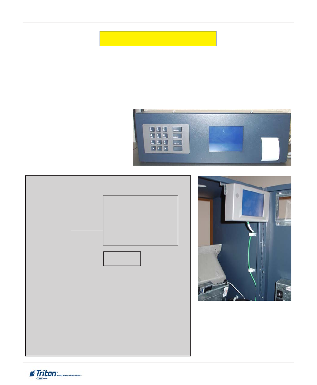
REAR OPERATOR PANELS
The Rear Operator Panels provide convenient user-access to limited Management functions from inside the
facility. The FT5000 rear panel (currently) has a self-contained enclosure with a display , keypad, and printer .
The RT2000 rear display has a touchpad screen (no printer).
Note: Future implementation for the FT5000 rear service panel will change to the touchpad screen
used for the RT2000.
Basic functions available are T
ROR, SHUT DOWN and RESET TERMINAL.
ERMINAL CLOSE, DIAGNOSTICS, ELECTRONIC JOURNAL, RESET TERMINAL ER-
FT5000 Rear Service Panel
OPERA TOR SER VICE PANEL (MAIN MENU)
TERMINAL CLOSE
TRIAL CLOSE
DAY CLOSE
TRIAL CASSETTE CLOSE
CASSETTE CLOSE
DIAGNOSTICS
CURRENT TERMINAL ERROR
DISPENSER
CARD READER STATUS
PRINTER
MODEM/ETHERNET
KEYPAD
ELECTRONIC JOURNAL
DISPLAY UNAUDITED RECORDS CLEAR JOURNAL
DISPLAY LAST XJOURNAL RECORDS
RESET TERMINAL ERROR
SHUT DOWN THE TERMINAL
RESTART THE TERMINAL
SELECT CASSETTE(S) TO CLOSE
CLOSE REPORT
REMOVE/REPLENISH CASSETTE(S)
EINSTALL CASSETTE(S)
R
P
LACE CASSETTE(S) IN-SERVICE
ENTER CASSETTE QUANTITY
TRIAL CASSETTE CLOSE REPORT
PURGE
TEST DISPENSE
RT2000 Operator Service Panel
10
Page 21
TERMINAL CLOSE FUNCTIONS
Page 22
X-SCALE / X2 CONFIGURATION MANUAL
TERMINAL CLOSE FUNCTIONS
TERMINAL CLOSE FUNCTIONS MENU OPTIONS OVERVIEW............................................... 13
S
CHEDULE CLOSE .......................................................................................................... 14
S
END TERMINAL TOTALS (ON/OFF) ................................................................................. 15
T
RIAL CLOSE / DAY CLOSE ............................................................................................ 16
T
RIAL CASSETTE CLOSE .................................................................................................. 17
CASSETTE CLOSE .......................................................................................................18-20
12
Page 23
TERMINAL CLOSE FUNCTIONS
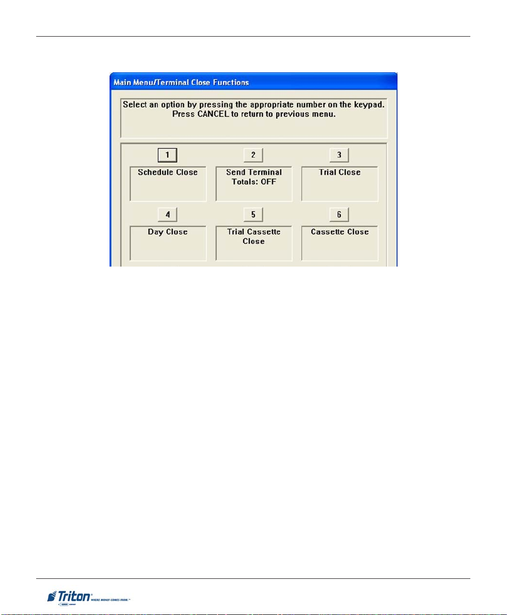
TERMINAL CLOSE FUNCTIONS
ACCESS INSTRUCTIONS:
1 . From the M
keypad.
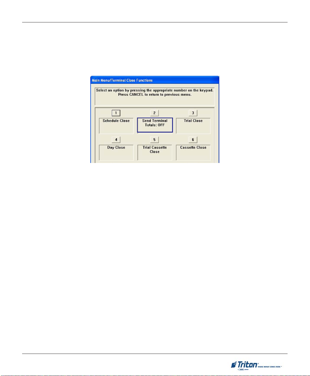
DESCRIPTION:
The T
ERMINAL CLOSE menu allows the terminal operator to perform the following functions:
CHEDULE CLOSE. Used to enable/disable and set time for automatic day closes.
1. S
AIN MENU screen, select the TERMINAL CLOSE FUNCTIONS option by pressing <1> on the
2. SEND TERMINAL TOTALS. Used to enable/disable automatic transmission of terminal close totals to
your transaction processing service provider. Press this button to cycle the function between ON or
OFF.
RIAL CLOSE. Used to initiate a trial day close.
3. T
4. D
AY CLOSE. Used to initiate a day close.
RIAL CASSETTE CLOSE. Used to provide a receipt/record of the cassette(s) balance.
5. T
6. CASSETTE CLOSE FUNCTIONS. Used to access a menu of cassette close and cassette configuration
functions.
13
Page 24
X-SCALE / X2 CONFIGURATION MANUAL
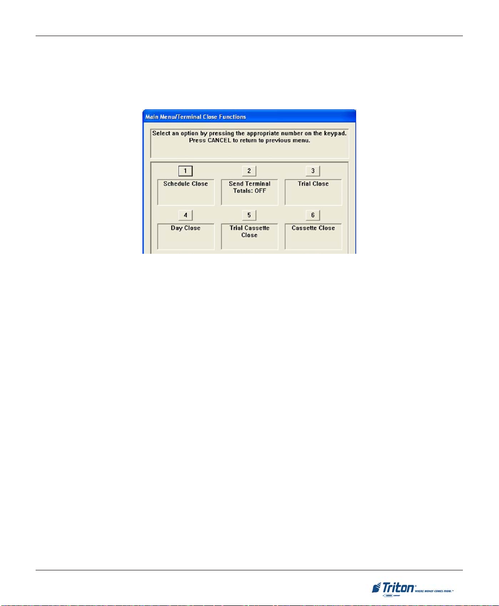
SCHEDULE CLOSE
ACCESS INSTRUCTIONS:
1 . From the T
the keypad.
DESCRIPTION:
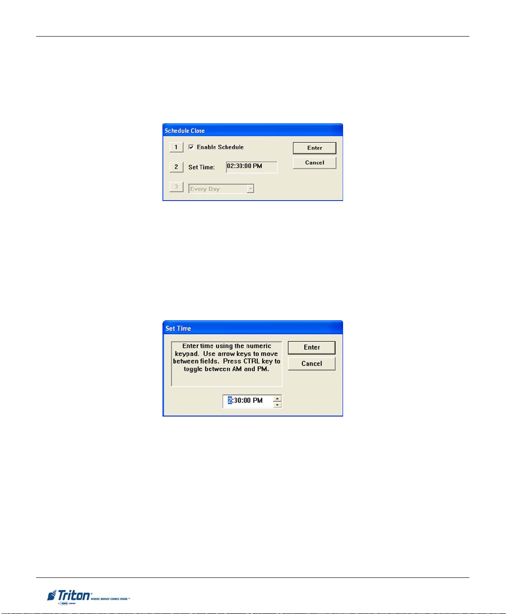
The SCHEDULE CLOSE function allows you to enable/disable scheduled closes and to specify when that will
be performed.
Press <1> on the keypad to either enable (check) or disable (uncheck). When enabled, menu
option (2) will be accessible.
Press <2> on the keypad.
ERMINAL CLOSE FUNCTIONS screen, select the SCHEDULE CLOSE option by pressing <1> on
Use the keypad to enter hours, minutes, and seconds. Use the <ARROW> keys on the keypad to move
between the fields. Press the <CTRL> key to toggle between AM and PM at which the scheduled close is
to be performed. The current time setting appears in a small text window .
Press <E
NTER> to accept the settings and return to the T erminal Close Functions main window.
14
Page 25
TERMINAL CLOSE FUNCTIONS
SEND TERMINAL TOTALS
ACCESS INSTRUCTIONS:
1. From the T
SEND TERMINAL TOTALS option between <ON> or <OFF>.
DESCRIPTION:
This function allows turning ON or OFF the SEND TERMINAL TOTALS option. The current state of the feature
is shown - ON / OFF.
When the option is ON, the terminal will send accumulated totals information to your transaction processing service provider during the Day Close operation. If the option is set to OFF , these totals will not be sent.
Terminal totals include the total value of all withdrawal, inquiry, and transfer transactions that have occurred since the last Day Close operation (see the description of the Day Close function for additional
information).
ERMINAL CLOSE FUNCTIONS screen, press <2> on the keypad to toggle the state of the
15
Page 26
X-SCALE / X2 CONFIGURATION MANUAL
TRIAL CLOSE / DAY CLOSE
ACCESS INSTRUCTIONS:
1 . From the T
the TRIAL CLOSE option by pressing <3> on the key-
pad.
2. From the Terminal Close Functions screen, select
the D
pad..
ESCRIPTION:
D
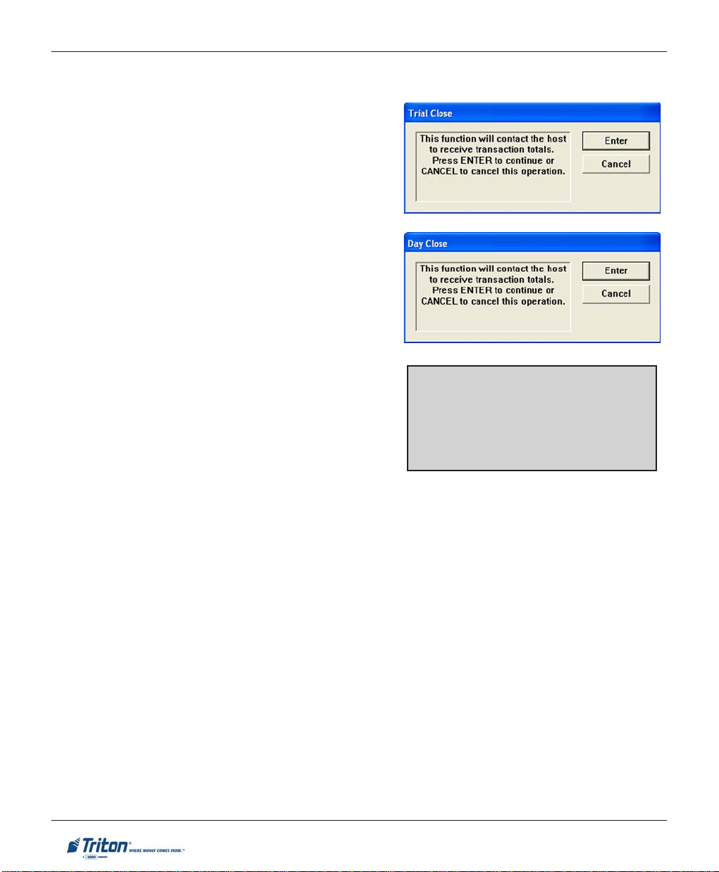
The T
RIAL CLOSE function is used during the daily close
procedure. It performs the same function as the Day Close,
except that the totals are not cleared.
The report printed by the Trial Close is used to balance
your cash dispenser before you actually balance with your
processor. It contains accumulated transaction totals obtained from the processor and from the terminal itself. The
report shows the total number of customer transactions
(withdrawals, inquiries and transfers) recorded by the processor and the terminal since the last day close was performed. The two-column format allows the host and terminal totals in each category to be easily compared. The
‘Settlement $’ value is the host processor’s record of the
total currency dispensed from the terminal since the last
day close was performed.
ERMINAL CLOSE FUNCTIONS screen, select
AY CLOSE option by pressing <4> on the key-
*NOTE*
If the Day Close is not performed at the
same time as the processors’ day close,
the host and terminal totals may not
match.
AY CLOSE function is used to complete daily balancing of the cash dispenser with the processor. The
The D
Day Close is performed to clear the totals and switch to the next business day. This function prints a report
summarizing all of the transactions performed since the last Day Close was completed. The information
includes a total of all transactions. This function also calls your processor’s host system and downloads
the totals it has accumulated for the current business day.
The Day Close is normally completed as the final step in the daily balancing process. You may wish to
perform a Trial Close before the Day Close, to view the report without clearing the accumulated transac-
tion totals.
The report is displayed in a management report dialog which can be printed to the receipt printer or saved
to an external memory device.
16
Page 27
TERMINAL CLOSE FUNCTIONS
TRIAL CASSETTE CLOSE
A
CCESS INSTRUCTIONS:
1. From the T
<5> on the keypad.
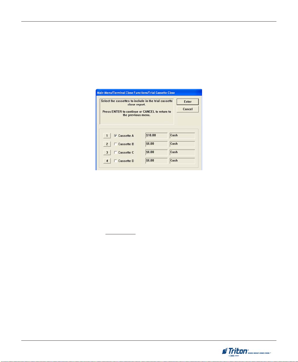
2 . Select which cassette(s) to include in the Trial Cassette Close report ( a checkmark denotes selected
cassette). Press <ENTER>.
DESCRIPTION:
The T
RIAL CASSETTE CLOSE function is used to complete the balancing of a specific currency cassette(s) of
the terminal with out resetting the values to zero. This function displays a report summarizing all activity on
the cash dispenser for the selected cassette since the last cassette close was completed. The report includes a total of all transactions.
The Trial Cassette Close is normally used to provide a quick look at the current status of the cassette(s).
Completing a Trial Cassette Close DOES NOT clear the cassette totals from the terminal.
ERMINAL CLOSE FUNCTIONS screen, select the TRIAL CASSETTE CLOSE option by pressing
The Trial Cassette Close report is displayed in a management report dialog which can be printed to the
receipt printer or saved to an external memory device.
17
Page 28
X-SCALE / X2 CONFIGURATION MANUAL
CASSETTE CLOSE
ACCESS INSTRUCTIONS:
1 . From the T
the keypad (or select CASSETTE CLOSE on the REAR SERVICE PANEL, if applicable).
DESCRIPTION:
ASSETTE CLOSE function is used to complete the balancing of a specific currency cassette(s) of the
The C
terminal. This function displays a report summarizing all activity on the cash dispenser for the selected
cassette(s) since the last cassette close was completed. The report includes a total of all transactions.
The cassette close is normally completed as the final step in balancing a currency cassette before removing
it to be replenished. Completing a cassette close CLEARS the cassette totals from the terminal.
The Cassette Close report is displayed in a management report dialog which can be printed to the receipt
printer or saved to an external memory device.
ERMINAL CLOSE FUNCTIONS screen, select the CASSETTE CLOSE option by pressing <6> on
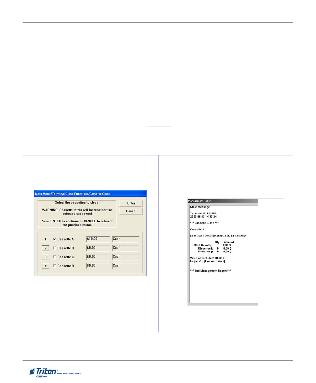
Select the cassette(s) to Close. A checkmark
identifies which cassette(s) are selected. Press
<ENTER>.
A CLOSE report is presented to be either printed
or saved. Close operation also resets the number
of bills loaded to zero (0). Press <ENTER> to
continue.
18
Page 29
TERMINAL CLOSE FUNCTIONS
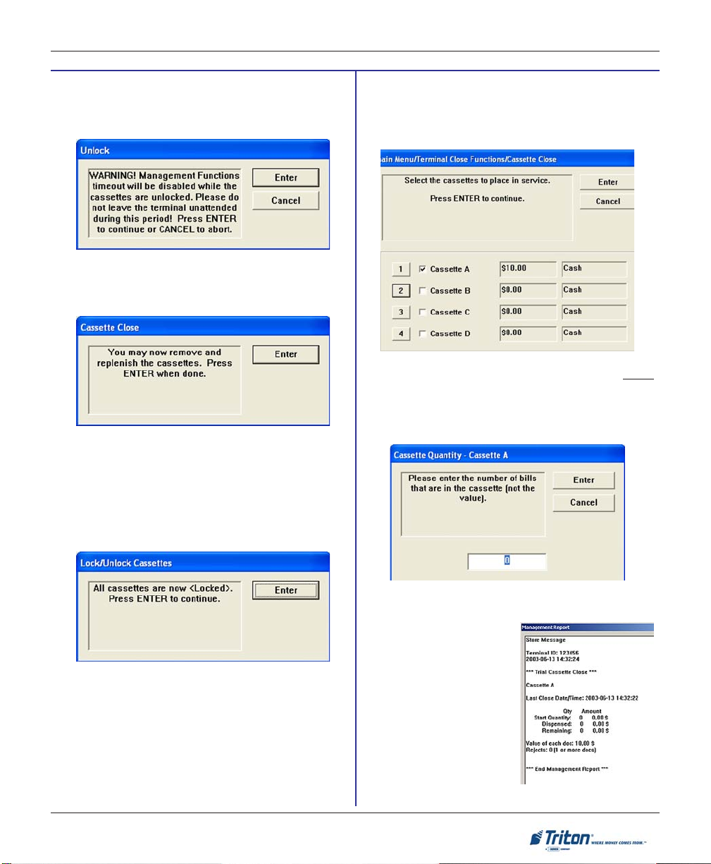
Note: For NMD-50/100 only, cassettes will
automatically U
R
EMOVE and REPLENISH selected cassette(s).
After reinserting cassette(s), press <ENTER>.
NLOCK.
Note: For NMD-50/100 only, cassettes will
automatically LOCK. Press <ENTER>.
For the NMD-50/100 dispensing mechanisms, the
cassettes MUST be LOCKED and IN-SERVICE for
normal operation
.
Place selected cassette(s) IN SERVICE (MULTI-
CASSETTE DISPENSERS ONLY). Press <ENTER> to
continue.
Enter CASSETTE QUANTITY (# of notes, NOT
value) for selected cassette. Press <ENTER> to
accept the entry. Repeat for remaining
cassette(s).
A TRIAL CASSETTE
CLOSE report appears to be
printed or saved. Press
<ENTER> after printing and
retain copy for starting
point reference.
19
Page 30

X-SCALE / X2 CONFIGURATION MANUAL
CASSETTE CLOSE
(REAR SERVICE PANEL)
OPERA TOR SER VICE PANEL (MAIN MENU)
TERMINAL CLOSE
TRIAL CLOSE
DAY CLOSE
TRIAL CASSETTE CLOSE
CASSETTE CLOSE
DIAGNOSTICS
SELECT CASSETTE(S) TO CLOSE
CLOSE REPORT
REMOVE/REPLENISH CASSETTE(S)
EINSTALL CASSETTE(S)
R
P
LACE CASSETTE(S) IN-SERVICE
ENTER CASSETTE QUANTITY
TRIAL CASSETTE CLOSE REPORT
CURRENT TERMINAL ERROR
DISPENSER
CARD READER STATUS
PURGE
TEST DISPENSE
PRINTER
MODEM/ETHERNET
KEYPAD
ELECTRONIC JOURNAL
DISPLAY UNAUDITED RECORDS CLEAR JOURNAL
DISPLAY LAST XJOURNAL RECORDS
RESET TERMINAL ERROR
SHUT DOWN THE TERMINAL
RESTART THE TERMINAL
20
Page 31

DIAGNOSTICS
Page 32

X-SCALE / X2 CONFIGURATION MANUAL
DIAGNOSTICS FUNCTIONS
DIAGNOSTICS FUNCTIONS MENU OPTIONS ................................................................ 24-25
TERMINAL STA TUS........................................................................................................... 26
CURRENT TERMINAL ERROR / ERROR HISTORY ............................................................................................. 27
RESET TERMINAL ERROR / CONFIGURATION SUMMARY ................................................................................. 28
RESTORE DEFAULT PARAMETERS ................................................................................................................. 29
SAVE / RESTORE PARAMETERS USING AN EXTERNAL STORAGE DEVICE ........................................................... 30
TRANSACTION TOTALS / SYSTEM DIAGNOSTICS .............................................................. 31
22
Page 33

DIAGNOSTICS
DISPENSER ..................................................................................................................... 32
CASH DISPENSER STATUS / PURGE ............................................................................................................... 33
EST DISPENSE .......................................................................................................................................... 34
T
INJECT NEW CASSETTE ID (NMD ONLY) .................................................................................................... 35
ORCE UNLOCK CASSETTE (NMD ONLY) .................................................................................................... 36
F
DISPENSER TOTALS / RESET DISPENSER ....................................................................................................... 37
C
ASSETTE PARAMETERS ..................................................................................................................................... 38-39
CARD READER ............................................................................................................... 40
CARD READER STATUS / TOTALS ................................................................................................................. 40
CAN CARD .............................................................................................................................................. 41
S
PRINTER ......................................................................................................................... 42
PRINTER STATUS ......................................................................................................................................... 42
RESET/TEST PRINTER / CONFIGURE PRINTER ................................................................................................ 43
MODEM/ETHERNET ......................................................................................................... 44
DEVICE STATUS / TEST ............................................................................................................................... 45
M
ODEM TOTALS ........................................................................................................................................ 46
CONFIGURE MODEM / TRITON CONNECT SETTINGS .......................................................................................... 47-48
C
ONFIGURE ETHERNET SETTINGS ...................................................................................................................... 49-50
MODEM SETUP STRING .............................................................................................................................. 51
KEYP AD ......................................................................................................................... 52
DEVICE STATUS / TEST ............................................................................................................................... 52
GENERAL I / O DIAGNOSTICS ......................................................................................... 53
LED INDICATORS / AUDIO OUTPUT / HEADPHONE INTERRUPTS / CONFIGURE LED FLASH RATE .................... 53
TCP/IP WIRELESS ......................................................................................................... 54
23
Page 34

ACCESS INSTRUCTIONS:
1. From the M
AIN MENU screen, select the DIAGNOSTICS option by pressing <2> on the keypad.
X-SCALE / X2 CONFIGURATION MANUAL
DIAGNOSTICS
* Wireless Option if used.
DESCRIPTION:
IAGNOSTICS option allows the terminal operator to perform the following functions:
The D
1. TERMINAL STATUS. Displays current terminal status, configuration summary, and parameter save/
restore functions.
2. TRANSACTION TOTALS. Displays terminal transaction totals since the last Day Close.
YSTEM DIAGNOSTICS. Displays a dialog that allows the terminal operating system properties to be
3. S
viewed.
4. DISPENSER. Allows user to check dispenser status, perform diagnostics, and configure cassette
parameters.
5. CARD READER. Displays card reader status and test functions.
24
Page 35

DIAGNOSTICS
6. PRINTER. Displays printer status and test functions.
ODEM / ETHERNET. This function allows user to view Modem / Ethernet device status, test functions,
7. M
and configure if required.
8. KEYPAD. Displays keypad status and tests terminal key functionality . When EPP (keypad) displays
tamper/serial errors, activates an option <4> to reset error.
9. G
ENERAL I / O DIAGNOSTICS. Provides access to perform diagnostics on LED indicators, audio
output, and headphone interrupts.
*0. TCP/IP WIRELESS. This function appears when the terminal is using TCP/IP wireless communication
as its protocol (TERMINAL CONFIGURATION > COMMUNICATION setup). The available options provide
signal strength indication and connect/disconnect ability.
NOTE: This option was available for wireless RL5000 units equipped with the LandCell wireless
modems which Triton no longer offers. For wireless-capable option, contact your account representative.
25
Page 36

ACCESS INSTRUCTIONS:
1. From the D
IAGNOSTICS screen, select the TERMINAL STATUS option by pressing <1> on the keypad.
X-SCALE / X2 CONFIGURATION MANUAL
TERMINAL STATUS
DESCRIPTION:
The TERMINAL STATUS option allows the terminal operator to perform the following functions:
1. CURRENT TERMINAL ERROR. Displays current error status of the terminal.
ERMINAL ERROR HISTORY. Displays a log of all terminal error events.
2. T
ESET TERMINAL ERROR. Allows user to attempt to reset the current terminal error.
3. R
ONFIGURATION SUMMARY. Displays a comprehensive report of all terminal configuration information.
4. C
5. R
ESTORE DEFAULT PARAMETERS. This function restores the factory default parameter settings.
AVE PARAMETERS TO EXTERNAL STORAGE. Allows user to save all current terminal parameters to an
6. S
external memory device (jumpdrive).
7. RESTORE PARAMETERS FROM EXTERNAL STORAGE. Allows user to restore terminal parameters that
were previously saved to an external memory device (jumpdrive).
26
Page 37

DIAGNOSTICS
CURRENT TERMINAL ERROR / ERROR HISTORY
ACCESS INSTRUCTIONS:
1 . From the T
the keypad.
2 . From the TERMINAL STATUS screen, select the TERMINAL ERROR HISTORY option by pressing <2> on
the keypad.
ERMINAL STATUS screen, select the CURRENT TERMINAL ERROR option by pressing <1> on
ESCRIPTION:
D
The CURRENT TERMINAL ERROR function displays a management report that shows the most current termi-
nal status/error code. The error code is listed with a short description of the condition.
The report is displayed in a management report dialog, which can be printed to the receipt printer or saved
to an external memory device.
ERMINAL ERROR HISTORY function displays a management report showing all status/error codes that
The T
have been recorded since the initial terminal setup. A short description of each code is provided. The
history of terminal status/error codes will not be cleared when the ‘Reset T erminal Error” function is used.
The report is displayed in a management report dialog, which can be printed to the receipt printer or saved
to an external memory device.
27
Page 38

X-SCALE / X2 CONFIGURATION MANUAL
RESET TERMINAL ERROR
ACCESS INSTRUCTIONS:
1 . From the T
keypad.
DESCRIPTION:
ESET TERMINAL ERROR function attempts to reset the current terminal error. If successful, the current
The R
terminal error will show: Zero (0)
ERMINAL STATUS screen, select the RESET TERMINAL ERROR option by pressing <3> on the
CONFIGURATION SUMMARY
ACCESS INSTRUCTIONS:
1. From the T
ERMINAL STATUS screen, select the CONFIGURATION SUMMARY option by pressing <4> on
the keypad.
D
ESCRIPTION:
ONFIGURATION SUMMARY function displays a management
The C
report of the current terminal configuration and hardware status information. Information is provided for all terminal configuration areas, as well as dispenser, printer , modem and keypad status.
The report is displayed in a management report dialog, which
can be printed to the receipt printer or saved to an external
memory device.
* NOTE *
It is highly recommended that the report be generated and
saved after the initial setup of the terminal, and whenever
significant changes are made to the terminal’s current configuration.
28
Page 39

DIAGNOSTICS
RESTORE DEFAULT PARAMETERS
ACCESS INSTRUCTIONS:
1 . From the T
on the keypad.
ESCRIPTION:
D
ESTORE DEFAULT PARAMETERS function restores the factory-default terminal parameter settings. All
The R
current parameters (including any that have been modified from their factory-default values) will be DE-
LETED and the factory-default values will be restored. When prompted, select <ENTER> to continue.
ERMINAL STATUS screen, select the RESTORE DEFAUL T PARAMETERS option by pressing <5>
A confirmation dialog is displayed. Select <ENTER> to return to Terminal Status options.
29
Page 40

X-SCALE / X2 CONFIGURATION MANUAL
SAVE / RESTORE PARAMETERS USING AN EXTERNAL STORAGE DEVICE
ACCESS INSTRUCTIONS:
1. From the T
pressing <6> on the keypad.
2 . From the TERMINAL STATUS screen, select the RESTORE PARAMETERS FROM EXTERNAL STORAGE option
by pressing <7> on the keypad.
DESCRIPTION:
The S
AVE PARAMETERS TO EXTERNAL STORAGE function saves the current terminal parameters to an external
storage device (jumpdrive) attached to a USB port.
Open the control panel. Install the jumpdrive to any unused USB port.
Close the control panel. Select <6> on the keypad. The following prompts appear . Press <Enter>
to continue.
ERMINAL STATUS screen, select the SAVE PARAMETERS TO EXTERNAL STORAGE option by
At the confirmation dialog, open the control panel and remove the jumpdrive.
ESCRIPTION:
D
ESTORE PARAMETERS FROM EXTERNAL STORAGE function restores a previously saved set of parameters
The R
from an external storage device (jumpdrive).
Open the control panel. Install the jumpdrive
to any unused USB port.
Close the control panel. Select <7> on the
keypad. The following prompt appears.
Locate the filename for the saved parameters.
Press <Enter> to select the highlighted file.
At the confirmation dialog, open the control
panel and remove the jumpdrive.
30
Page 41

DIAGNOSTICS
TRANSACTION TOTALS / SYSTEM DIAGNOSTICS
ACCESS INSTRUCTIONS:
1. From the D
keypad.
2. From the DIAGNOSTICS screen, select the SYSTEM DIAGNOSTICS option by pressing <3> on the keypad.
IAGNOSTICS screen, select the TRANSACTION TOTALS option by pressing <2> on the
DESCRIPTION:
RANSACTION TOTALS report displays totals in two (2) categories: T otals since last close and cumula-
The T
tive totals. The report also provides the date/time of the last completed transaction and denied transaction.
The report can be printed to the receipt printer or saved to an external memory device.
The S
YSTEM DIAGNOSTICS function will display a dialog that allows the system properties to be viewed and
configured.
To navigate through the dialog, press the Clear key on the keypad to tab between areas. Use the left and
right arrow keys to move between items in an area. T o exit from the dialog, press the Cancel key .
In most cases it should not be necessary to make change any of these system properties.
31
Page 42

ACCESS INSTRUCTIONS:
1. From the D
IAGNOSTICS screen, select the DISPENSER option by pressing <4> on the keypad.
X-SCALE / X2 CONFIGURATION MANUAL
DISPENSER
DESCRIPTION:
The DISPENSER option allows the terminal operator to perform the following functions:
1. CASH DISPENSER STATUS. Displays a management report showing current dispenser hardware status.
2. P
URGE. Performs a purge operation on the dispenser.
3. T
EST DISPENSE. This function commands the dispenser to dispense a single note (min) from each
installed and active cassette into either the Reject cassette, compartment, or vault (dispenser specific).
SHUTTER TEST (FT5000 ONLY). This function runs a functional test of the units’ dispenser shutter
assembly.
4. I
NJECT NEW CASSETTE ID (NMD ONLY). This function allows changing the cassette(s) identification.
5. F
ORCE UNLOCK CASSETTE (NMDONLY). This function enabled overriding the dispenser cassette
locking mechanism.
6. D
ISPENSER TOTALS. Displays a management report showing total number of documents dispensed.
7. R
ESET DISPENSER. This function resets ALL dispenser and cassette parameters to default values.
8. C
ASSETTE PARAMETERS. Allows configuring cassette parameters (currency data, multiple amounts,
etc).
9. C
LEAR DISPENSER STATUS REPORT (TDMS ONLY). This function will reset the count in the “Since
Reset” column on the Dispenser Data report.
32
Page 43

DIAGNOSTICS
CASH DISPENSER STATUS
ACCESS INSTRUCTIONS:
1. From the D
2 . From the DISPENSER screen, select the CASH DISPENSER STATUS option by pressing <1> on the keypad.
DESCRIPTION:
ASH DISPENSER STATUS report identifies the type of dis-
The C
pensing mechanism installed and displays the results of the
most recent cash dispenser status check.
The report is displayed in a management report dialog that
can be printed to the receipt printer or saved to an external
memory device.
IAGNOSTICS screen, select the DISPENSER option by pressing <4> on the keypad.
PURGE
ACCESS INSTRUCTIONS:
1. From the DIAGNOSTICS screen, select the DISPENSER option by pressing <4> on the keypad.
2. From the D
ESCRIPTION:
D
The P
URGE command instructs the dispenser to remove all documents from the feed path. When the purge
command is used to clear the feed path following a jam or failure of the dispenser, some or all of the notes
may pass out of the exit depending on their location in the feed path and the type of fault condition.
Once the purge command is completed, the user will be prompted to either repeat the purge operation or exit
and go back to the Dispenser menu.
ISPENSER screen, select the PURGE option by pressing <2> on the keypad.
33
Page 44

X-SCALE / X2 CONFIGURATION MANUAL
TEST DISPENSE
ACCESS INSTRUCTIONS:
1. From the D
2 . From the DISPENSER screen, select the TEST DISPENSE option by pressing <3> on the keypad.
ESCRIPTION:
D
The TEST DISPENSE command allows the user to dispense note(s) from each installed and operational cassette
into the reject cassette. This test exercises the dispenser mechanism without sending notes to the exit. The
Test Dispense can only be exercised on the cassettes installed.
Once the cassette information is retrieved, the user will be prompted to enter the number of note(s) to be
dispensed from cassette A through D, if applicable. The values for the number of notes are 1 to 5. If the user
enters a number greater than 5, it will automatically default to 5.
IAGNOSTICS screen, select the DISPENSER option by pressing <4> on the keypad.
Shutter Test
Press the number on the keypad for the cassette(s) and enter the desired value. Press <E
NTER>. Repeat for
the remaining cassettes that are available.
Next, press the <ENTER> key to perform the test. The dispenser will dispense the note(s) from the cassette(s)
into the reject cassette, compartment, or reject vault, if applicable.
When the test is completed, the user will be prompted that test was completed successfully.
The SHUTTER TEST exercises the unit’s shutter assembly (Open/Close). This function will be available for
FT5000 units. Caution: T ake care not to insert any objects or fingers when assembly is opening/closing.
34
Page 45

DIAGNOSTICS
INJECT NEW CASSETTE ID (NMD ONLY)
ACCESS INSTRUCTIONS:
1. From the D
2 . From the CASH DISPENSER screen, select the INJECT NEW CASSETTE ID option by pressing <4> on the
keypad.
DESCRIPTION:
The NMD dispensing mechanisms use cassettes that possess onboard memory. This memory enables a
cassette to store its own identification (ID) code.
NJECT NEW CASSETTE ID function has no direct correlation to the physical position of the cassette within
The I
the unit. In most instances, the cassette identified as “A” will be placed in the top feed channel, “B” in the
second, and continuing. This is not a requirement since the ID code allows the dispensing mechanism (and
the dispensers central controller) to locate the cassette wherever it’s been placed in the dispenser.
This function allows injecting a new ID into a cassette. Insert the cassette you want to ID into the
channel. Press the button corresponding to the identity you want the cassette to have: ‘A’, ‘B’, ‘C’, or ‘D’.
IAGNOSTICS screen, select the CASH DISPENSER option by pressing <1> on the keypad.
top feed
When the ID has successfully been injected, a message prompt will appear. If the operation fails, an error
message will appear. After successfully completing the ID injection, you can place the cassette in its normal operating
position.
35
Page 46

X-SCALE / X2 CONFIGURATION MANUAL
FORCE UNLOCK Cassette (NMD only)
ACCESS INSTRUCTIONS:
1. From the D
2 . From the C
keypad.
DESCRIPTION:
The F
ORCE UNLOCK CASSETTE function provides a means of overriding the NMDs unlocking mechanism
associated with a specific cassette. It is only to be used immediately after failure of a normal cassette unlock
operation.
Occasionally, a condition may occur that prevents a cassette from being removed from the dispensing
mechanism. For example, a note that is lodged or jammed in a cassettes’s ‘gate’ could cause such a condition. The gate is a mechanical shutter on the feed end of a cassette which lowers to allow notes to be
dispensed and raises as a security precaution when the cassette is removed.
During a normal unlocking operation when the gate is closed, the cassette releases an associated mechanical latch allowing the cassette to be removed from the body of the dispenser. If the gate does not fully close,
the cassette will not release the latch and remains locked in the mechanism.
If you find that a particular cassette can not be removed after performing a normal unlock operation, use this
function
first to attempt releasing the applicable cassette from the mechanism.
Once the cassette has been removed from the dispenser, carefully remove any notes that are sticking out of
cassette. Insert the cassette into the dispenser and perform a normal ‘Lock’ operation followed by a normal
‘Unlock’ operation. You may now remove the cassette.
IAGNOSTICS screen, select the CASH DISPENSER option by pressing <1> on the keypad.
ASH DISPENSER screen, select the FORCE UNLOCK CASSETTE option by pressing <5> on the
36
Page 47

DIAGNOSTICS
DISPENSER TOTALS / RESET DISPENSER
A
CCESS INSTRUCTIONS:
1. From the D
2. From the CASH DISPENSER screen, select the DISPENSER TOTALS option by pressing <6> on the
keypad.
3 . From the C
DESCRIPTION:
The DISPENSER TOTALS function displays dispenser activity totals in various categories. Cumulative dispense and
reject counts for the dispenser as well as individual totals
for each installed cassette are provided.
The report is displayed in a management report dialog,
which can be printed to the receipt printer or saved to an
external memory device.
IAGNOSTICS screen, select the CASH DISPENSER option by pressing <1> on the keypad.
ASH DISPENSER screen, select the RESET DISPENSER option by pressing <7> on the keypad.
ESET DISPENSER function resets the operating parameters associated with the dispenser and its asso-
The R
ciated cassette(s). This operation will generally be performed when a new dispenser is added or there is a
problem with the current dispenser.
Select <E
NTER> to reset the dispenser or <CANCEL> to exit without resetting the dispenser.
** CAUTION **
If you select this option, you will lose AL L cassette parameters (amount,value, etc) that have been
previously configured. This option resets the cassette parameters to the factory default settings.
37
Page 48

X-SCALE / X2 CONFIGURATION MANUAL
CASSETTE PARAMETERS
ACCESS INSTRUCTIONS:
1. From the D
2. From the CASH DISPENSER screen, select the CASSETTE PARAMETERS option by pressing <8> on the
keypad.
IAGNOSTICS screen, select the CASH DISPENSER option by pressing <1> on the keypad.
DESCRIPTION:
ASSETTE PARAMETERS option allows the terminal operator to perform the following functions:
The C
1. R
ELEARN BILL THICKNESS. Relearn the thickness of the documents loaded in the cassette.
2. A
LL CASSETTES LOCKED / UNLOCKED (NMD-ONLY). Physically lock or unlock A LL cassettes in the
dispensing mechanism chassis.
3. R
ETRACT CASH (NMD-ONLY). Enable/disable the automatic retraction of the bundle carriage unit,
which transports the documents to the output slot of the dispenser.
E
NABLE EXTENSION REJECTS (TDM-200/250). When enabled, allows the extension to automatically
purge any notes detected as remaining in the extension. The purge is done at power up or as part of
a dispenser operation.
ETRACT DELAY (NMD ONL Y). Determine the amount of time the dispenser will wait before retracting
4. R
the bundle carriage unit.
38
Page 49

DIAGNOSTICS
5. ACTIVE CASSETTE. Select the cassette that will receive the results of any changes to the various
cassette and note configuration parameters that are accessed via the cassette parameters dialog.
6. C
ASSETTE IN SERVICE (MULTI-CASSETTE DISPENSERS). Places the currently selected cassette ‘In Ser-
vice” or “Out of Service”.
7. M
ULTIPLE AMOUNT. Set the denomination of the currency in a cassette.
8. D
OCUMENT TYPE. Enter the type of document in the selected cassette: Cash or non-cash.
Note: Single cassette dispensers and ALL TDMs are always set for “Cash”.
ON-CASH ITEM DESCRIPTION (NMD ONLY). Enter up to 28 characters describing the non-cash item in
9. N
the active cassette.
0. S
ECONDARY ITEM DESCRIPTION (NMD ONLY). Enter up to 28 characters of general information about
the non-cash item in the active cassette or other information as required.
F1 N
OTE CONFIGURATION. This function allows you to configure the note specific operating parameters
for the active cassette.
* NOTE *
For further information on the individual Cassette Parameters, refer to OPTION 6, TERMINAL
CONFIGURA TION > CASSETTE SETUP > CASSETTE PARAMETERS.
39
Page 50

X-SCALE / X2 CONFIGURATION MANUAL
CARD READER
ACCESS INSTRUCTIONS:
1. From the D
ESCRIPTION:
D
The CARD READER option allows the terminal operator to perform the following functions:
1. C
ARD READER STATUS. Displays a management report showing card reader hardware status.
ARD READER TOTALS. Displays a management report showing total number of various card reader
2. C
operations (cards read, bad cards read, last valid card read).
3. SCAN CARD. Verifies that data can be read properly by the card reader.
IAGNOSTICS screen, select the CARD READER option by pressing <5> on the keypad.
CARD READER STATUS / TOTALS
ACCESS INSTRUCTIONS:
1. From the DIAGNOSTICS screen, select the CARD READER option by pressing <5> on the keypad.
2. Select CARD READER STATUS by pressing <1> on the keypad.
3. Select C
ARD READER TOTALS by pressing <2> on the keypad.
40
Page 51

DIAGNOSTICS
SCAN CARD
ACCESS INSTRUCTIONS:
1. From the D
2 . From the CARD READER option, select SCAN CARD by pressing <3> on the keypad.
D
ESCRIPTION:
The S
CAN CARD function reports the number of tracks the card reader is able to scan. It prompts you to
insert and remove a card. Upon removing the card, a management report dialog is displayed. If the card can
be read properly, the information from the tracks on the card will be displayed. This report can be printed to
the receipt printer or saved to an external memory device.
IAGNOSTICS screen, select the CARD READER option by pressing <5> on the keypad.
If the card is damaged or not a standard format, an error message will be displayed. If this happens, the card
cannot be used for transactions on the terminal.
Press <3> on the keypad. When prompted, insert and remove a card. The dialog box will either verify
the tracks scanned or respond with an error message.
41
Page 52

X-SCALE / X2 CONFIGURATION MANUAL
PRINTER
ACCESS INSTRUCTIONS:
1. From the D
DESCRIPTION:
The P
RINTER option allows the terminal operator to perform the following functions:
1. D
EVICE STATUS. Displays a management report that shows properties of the terminal printer , such as
printer name, assigned port, driver version, and printer resolution.
2. R
EST / TEST PRINTER. This function tests the terminal printer by printing sample text using various
font styles and sizes.
3. C
ONFIGURE PRINTER. This function enables you to setup the operating parameters for the terminal
printer.
IAGNOSTICS screen, select the PRINTER option by pressing <6> on the keypad.
DEVICE STATUS
ACCESS INSTRUCTIONS:
1. From the DIAGNOSTICS screen, select the PRINTER op-
tion by pressing <6> on the keypad.
2. Select D
D
ESCRIPTION:
EVICE STATUS displays a report that shows properties of the
D
terminal printer, such as printer name, status, errors, etc.
The report is displayed in a Management Report dialog, which
can be printed to the receipt printer or saved to an external
memory device.
EVICE STATUS by pressing <1> on the keypad.
42
Store Message
Terminal ID: 75200
4/7/2008 11:00:00 AM
*** Device Status ***
Device ID: Seiko LTP2342
Device Status: 0 (Device Ready)
Online: Yes
Out Of Paper: No
Low Paper: No
Print Job Pending: No
Cover Open: No
Presenter Open: No
Hardware Error: No
Thermal Head Error: No
Voltage Error: No
Head Up Error: No
Auto Cut Error: No
Close Head Required: No
Printer presenter paper not detected.: No
Presenter Exit Blocked: No
Presenter Roller Blocked: No
Presenter Roller & Exit Blocked: No
Presenter Installed: Ye s
Presenter Stored: Yes
Paper Width: 80mm
Page 53

DIAGNOSTICS
RESET/TEST PRINTER / CONFIGURE PRINTER
ACCESS INSTRUCTIONS:
1. From the D
2. From the PRINTER option, select RESET / TEST PRINTER by pressing <2> on the keypad.
ESCRIPTION:
D
The R
ESET/TEST PRINTER function re-initializes and then performs an opera-
tional test of the printer. A pattern of characters is printed on the receipt.
ONFIGURE PRINTER function allows re-configuring of the printer’s de-
The C
fault settings. A maintenance keyboard should be used to interact with this
dialog screen. When this option is selected, a print setup prompt appears:
FONT SIZE - This allows changing the printed font characters to either
16 or 24 font.
LINE SPACING - Sets the spacing between lines on the receipt or coupon.
CHARACTER SPACING - Sets the spacing between characters on the
receipt or coupon.
RECEIPT FORMAT (PRINTER/PRESENTER) - Sets the receiptformat be-
tween “T ext” or “Graphics”.
IAGNOSTICS screen, select the PRINTER option by pressing <6> on the keypad.
MINIMUM RECEIPT LENGTH (GRAVITY-FED RL2000) - Sets the minimum
length for a customer receipt. Default is ‘1150’ [apprx 5-5/8" (144mm)].
If you don’t have an external keyboard, press the <CLEAR> to scroll
down/highlight the different options.
HE SCALE IS 8 DOTS = 1MM.
T
APPROXIMATE 200 DOTS = 1" (25.4MM)
Printer w/presenter
43
Printer w/o presenter
Page 54

ACCESS INSTRUCTIONS:
1 . From the D
IAGNOSTICS screen, select the MODEM/ETHERNET option by pressing <7> on the keypad.
X-SCALE / X2 CONFIGURATION MANUAL
MODEM / ETHERNET
DESCRIPTION:
The MODEM / ETHERNET option allows the terminal operator to perform the following functions:
1. DEVICE STATUS. Displays a management report that shows properties of the modems (dial-up and
TCP/IP) parameters.
2. T
EST. This function tests the modem by dialing a number that you enter in a dialog box. A status
report displays the progress and results of the operation.
3. M
ODEM TOTALS. Displays a management report showing the number of modem call attempts, busy
signals, and aborted calls.
4. C
ONFIGURE MODEM. Enables you to view and configure the modem’ s operating parameters.
5. T
RITON CONNECT SETTINGS. This function provides access to Triton Connect settings and
configuration parameters.
6. C
ONFIGURE ETHERNET SETTINGS. This function enables you to view and configure TCP/IP (Ethernet)
settings.
7. M
ODEM SETUP STRING. This function allows entering a non-standard setup string, if needed.
44
Page 55

DIAGNOSTICS
DEVICE STATUS / TEST
ACCESS INSTRUCTIONS:
1 . From the D
2 . From the MODEM/ETHERNET screen, select the DEVICE STATUS option by pressing <1> on the keypad.
3 . From the M
D
ESCRIPTION:
EVICE STATUS function displays a report that
The D
shows the current operational parameters of the modem (dial-up/TCP/IP).
This status is displayed in a management report dialog which can be printed to the receipt printer or
saved to an external memory device.
IAGNOSTICS screen, select the MODEM/ETHERNET option by pressing <7> on the keypad.
ODEM/ETHERNET screen, select the TEST option by pressing <2> on the keypad.
The TEST function tests the terminals modem. Enter a known good telephone number, which the modem will
dial to verify its ability to access the telephone line and perform a dialing operation.
Use the text entry box to enter the phone number. Select <E
NTER> to start the test or <CANCEL> to ignore the
entry and exit the function. At the conclusion of the test, a message box will indicate success or failure of the
test.
45
Page 56

X-SCALE / X2 CONFIGURATION MANUAL
MODEM TOTALS
A
CCESS INSTRUCTIONS:
1 . From the D
2 . From the MODEM/ETHERNET screen, select the MODEM TOTALS option by pressing <3> on the keypad.
IAGNOSTICS screen, select the MODEM/ETHERNET option by pressing <7> on the keypad.
DESCRIPTION:
The M
ODEM TOTALS function displays modem activity totals in two (2) categories: T otals since last close and
cumulative totals. T otal modem call attempts, successful connects, busy signal aborts, and date/time of the
last successful connection are recorded.
This report can be printed to the receipt printer or saved to an external storage device.
46
Page 57

DIAGNOSTICS
CONFIGURE MODEM / TRITON CONNECT SETTINGS
ACCESS INSTRUCTIONS:
1 . From the D
2. From the MODEM/ETHERNET screen, select the CONFIGURE MODEM option by pressing <4> on the
keypad.
3 . From the M
the keypad.
D
ESCRIPTION:
ONFIGURE MODEM and TRITON CONNECT SETTINGS functions allow changing the modem parameters.
The C
Pressing the applicable key (<4> for Configure Modem or <5> for T riton Connect Settings) will display the
Select Modem dialog. The name of the modem that will be configured is shown in the dialog.
IAGNOSTICS screen, select the MODEM/ETHERNET option by pressing <7> on the keypad.
ODEM/ETHERNET screen, select the TRITON CONNECT SETTINGS option by pressing <5> on
***WARNING***
Do not attempt to alter any of the following parameters unless you are absolutely certain of the result. If incorrectly set, some of these parameters can cause
communication failure.
Press the <CLEAR> key on the keypad until the “CONFIGURE” button is highlighted. Press the <ENTER>
key. The device properties screen is now displayed.
P
ORT SETTINGS
Press the <CLEAR> key until the parameter that will be configured is highlighted.
If the parameter is enabled (checked), highlight the parameter and press the <CTRL> key to place or
remove a check from the box. If the parameter is selected from a list of choices, use the <CLEAR> key to
highlight the parameter and the Right (>) and Left (<) arrow keys to display the desired parameter.
47
Page 58

X-SCALE / X2 CONFIGURATION MANUAL
This screen will allow you to view and configure the following modem properties from the Port Settings tab.
ITS PER SECOND. Baud rate setting for the terminal's modem.
1. B
ATA BITS. Number of data bits.
2. D
3. PARITY. Parity type: even or odd.
4. STOP BITS. Number of stop bits.
5. F
LOW CONTROL. Choose the type of flow control to use if required. In most cases the default
settings for the parameters in the configure dialog will satisfy your modem communication requirements; however, in some cases changes may be required to meet unique requirements. Usually , these
will be determined by your processor and configured by your service provider.
Once the necessary parameters have been selected, press the <CLEAR> key until the “PORT SETTINGS” tab
is highlighted. Press the Right (>) arrow key to display the parameters for the “CALL OPTIONS”. Use the
<CLEAR> key to highlight the parameter that will be configured.
C
ALL OPTIONS
If the parameter is enabled by placing a check in a box, highlight the parameter and press the <CTRL> key
to place or remove a check from the box. If the parameter is a numeric value, press the <C
LEAR> key until the
entry area is highlighted. Enter the number directly from the key pad. If the entry is a letter of the alphabet,
open the virtual key pad and use it for entering letters of the alphabet.
48
Page 59

DIAGNOSTICS
CONFIGURE ETHERNET SETTINGS
ACCESS INSTRUCTIONS:
1 . From the D
2 . From the MODEM/ETHERNET screen, select the CONFIGURE ETHERNET SETTINGS option by pressing <6>
on the keypad.
IAGNOSTICS screen, select the MODEM/ETHERNET option by pressing <7> on the keypad.
The CONFIGURE ETHERNET SETTINGS option allows the terminal operator to perform the following functions:
1. IP ADDRESS. This address identifies the terminal as the source of
the data packets sent to and received from the host server.
Change the IP Address by pressing <1> on the keypad. Enter
the new IP Address in the data entry dialog box. Press <E
2. SUBNET MASK. Along with the IP address, each port requires a
Subnet Mask address. This distinguishes other terminals on the
same Local Area Network (LAN) from terminals in other locations.
NTER>.
Change the Subnet Mask by pressing <2> on the keypad. Enter
the new address in the data entry dialog box. Press <E
49
NTER>.
Page 60

X-SCALE / X2 CONFIGURATION MANUAL
3. D
EFAULT GATEWAY. For direct access to networks beyond the
current one, each terminal must be told the IP address of the
router (Gateway) that connects the local network with the wider
world.
Change the Gateway address by pressing <3> on the keypad.
Enter the new address in the data entry dialog box. Press <EN-
TER>.
4. P
RIMARY DNS (Domain Name System). This address is an internet
service that translates domain names to IP addresses.
Change the Primary DNS by pressing <4> on the keypad. Enter
the new address in the data entry dialog box. Press <ENTER>.
5. PRIMARY WINS (Windows Internet Naming Service). This ad-
dress manages the association of workstation names and locations with IP addresses. WINS automatically creates a computer
name - IP address mapping entry in a table. WINS complements
the NT server’s DHCP which negotiates an IP address for any
computer when it is first defined to the network.
Change the Primary WINS address by pressing <5> on the key-
pad. Enter the new address in the data entry dialog box. Press
<Enter>.
6. ENABLE DHCP (Dynamic Host Configuration Protocol). This is a protocol that provides a means
to dynamically allocate IP addresses to computers on a LAN system.
T oggle the <6> key on the keypad to enable (checked) or disable (unchecked).
7. LOCAL PORTS. These options allow entering Incoming and /or Outgoing local port addresses.
INCOMING. Change the Incoming Port address by pressing <7> on the keypad. Enter the new port address
in the data entry dialog box. Press <ENTER>.
OUTGOING. Change the Outgoing Port address by pressing <8> on the keypad. Enter the new port address
in the data entry dialog box. Press <ENTER>.
Note: Incoming and Outgoing
Ports CANNOT be the same!
50
Page 61

DIAGNOSTICS
MODEM SETUP STRING
ACCESS INSTRUCTIONS:
1 . From the D
2 . From the MODEM/ETHERNET screen, select the MODEM SETUP STRING option by pressing <7> on the
keypad.
DESCRIPTION:
The M
ODEM SETUP STRING is used in special circumstances. A
Hayes-compatible setup string can be sent to the modem when it is
initialized.
Note: If needed, setting this value incorrectly will cause communication failure. Contact Triton Technical Support service before entering/changing this parameter.
IAGNOSTICS screen, select the MODEM/ETHERNET option by pressing <7> on the keypad.
51
Page 62

X-SCALE / X2 CONFIGURATION MANUAL
KEYPAD
ACCESS INSTRUCTIONS:
1 . From the D
2 . From the KEYPAD screen, select the DEVICE STATUS option by pressing <1> on the keypad.
3 . From the K
ESCRIPTION:
D
The DEVICE STATUS displays a management report that shows infor-
mation such as keypad status, serial number, version number, and
loaded encrypted key check digits.
IAGNOSTICS screen, select the KEYPAD option by pressing <8> on the keypad.
EYPAD screen, select the TEST option by pressing <2> on the keypad.
4
Clear Serial #
Error
The T
EST function enables you to verify operation of the numeric,
function, and control buttons on the terminal. Simply press any button (except the <Enter> button) and the status window will indicate
the state of the button: Up or Down. Press the <E
NTER> button when
completed.
Keypad/Screen Button Test
Press ENTER to Quit
Keypad 1, State: Down
Keypad 1, State: Up
Screen Button 1, State Down
Screen Button 1, State: up
The CLEAR SERIAL # OR TAMPER ERROR function
may be accessed if you have encountered either a
SPED Serial # error (617 - usually when keypad has
been replaced) or if a T amper condition has occured.
Press option <4> (if available) to attempt clearing
In the event the terminal displays Error Codes
ranging from 592-617 (keypad specific), option <4> in the Keypad functions may be an
available option. If it is, attempt to clear the
error by selecting this option.
either of these error conditions.
52
* NOTE *
Page 63

DIAGNOSTICS
GENERAL I / O DIAGNOSTICS
ACCESS INSTRUCTIONS:
1. From the D
keypad.
ESCRIPTION:
D
The GENERAL I/O DIAGNOSTICS option allows the terminal operator to perform the following functions:
1. LED INDICATORS. When selected, this function will flash all LEDs for 5 seconds.
2. AUDIO OUTPUT. Selecting this option will play a sound file and some audio text through the terminals
speaker system (or headphones if they are plugged in).
IAGNOSTICS screen, select the GENERAL I/O DIAGNOSTICS option by pressing <9> on the
EADPHONE INTERRUPTS. This option reports whether the headphones can be detected (inserted or
3. H
removed).
4. C
ONFIGURE LED FLASH RATE. Selecting this option will allow
the flash rate of the LEDs on the control panel to be altered to
one of the following:
0 Hz (always On)
0.5 Hz
1.0 Hz
2.0 Hz
Note: Default flash rate is 2.0 Hz.
5. CONFIGURE LED BRIGHTNESS (RL2000 ONLY). .Selecting this
option allows changing the LED brightness on the contrrol
panel.
Note: This option not available for RL/FT/RT units
53
Page 64

X-SCALE / X2 CONFIGURATION MANUAL
TCP/IP WIRELESS
ACCESS INSTRUCTIONS:
1 . From the D
NOTE: This option was available for wireless RL5000 units equipped with the LandCell wireless
modems which Triton no longer offers. For wireless-capable option, contact your account representative.
IAGNOSTICS screen, select the TCP/IP WIRELESS option by pressing <0> on the keypad.
54
Page 65

ELECTRONIC JOURNAL
ELECTRONIC JOURNAL
55
Page 66

X-SCALE / X2 CONFIGURATION MANUAL
ELECTRONIC JOURNAL FUNCTIONS
ELECTRONIC JOURNAL MENU OPTIONS OVERVIEW ......................................................... 57
DISPLAY UNAUDITED RECORDS ...................................................................................... 58
DISPLAY LAST X............................................................................................................ 59
DISPLAY SELECTED RECORDS ..................................................................................... 60-61
CLEAR JOURNAL ............................................................................................................ 62
RCHIVE / DELETE JOURNAL .......................................................................................... 63
A
V
IEW JOURNAL A RCHIVE ............................................................................................... 64
JOURNAL PROPERTIES .................................................................................................... 65
AUTO A RCHIVE ......................................................................................................... 66-67
56
Page 67

ACCESS INSTRUCTIONS:
1. From the M
AIN MENU screen, select the ELECTRONIC J OURNAL option by pressing <3> on the keypad.
ELECTRONIC JOURNAL
ELECTRONIC JOURNAL
DESCRIPTION:
The ELECTRONIC JOURNAL option allows the terminal operator to perform the following functions:
1. DISPLAY UNAUDITED RECORDS. This function displays a summary of the journal entries collected since
the last time the journal was printed.
2. DISPLAY LAST X. This function is used to display and print records either before or after they have
been audited.
3. D
ISPLAY SELECTED RECORDS. Generates a management report of journal entries that match a user-
defined set of filtering parameters.
LEAR JOURNAL. This function “marks” all unprinted records as audited.
4. C
5. ARCHIVE / DELETE JOURNAL. This function stores all journal entries prior to a selected date into an
archive file.
6. VIEW JOURNAL ARCHIVE. This function allows user to select and view an archived journal.
OURNAL PROPERTIES. Displays a management report that provides specific information about the
7. J
electronic journal (number of records, audited, unaudited).
8. A
UTO A RCHIVE. Sets the parameters to auto archive journal records based on specific date/time, size
limit, etc.
57
Page 68

ACCESS INSTRUCTIONS:
1. From the E
LECTRONIC JOURNAL menu screen, select the DISPLAY UNAUDITED RECORDS option by
pressing <1> on the keypad.
X-SCALE / X2 CONFIGURATION MANUAL
DISPLAY UNAUDITED RECORDS
DESCRIPTION:
The DISPLAY UNAUDITED RECORDS function is used to display a summary of all “unaudited” journal entries
collected since the last time the journal was printed. This information should be maintained in case of an
inquiry by a customer, and can also be useful in certain troubleshooting situations.
The report is displayed in a management report dialog that can be printed to the receipt printer or saved to
an external memory device. If used, an external memory device must be installed in a USB port “before” this
option is selected. The Display Unaudited Records saves journal files in a text (.txt) format. They can be
viewed by a text editor.
If the <C
ANCEL> or <ENTER> key is pressed after report
is displayed, printed, or saved the following prompt
will appear:
If the <ENTER> key is pressed as a response to the prompt, the requested action will be performed and all
“unaudited” records will be marked as “audited”. The only way to display them again is by using the
DISPLAY SELECTED RECORDS (*Audited* or *All*) or DISPLAY LAST X functions.
If the <CANCEL> key is pressed as a response to the prompt, the prompt will disappear and all “unaudited”
records will remain “unaudited”.
58
Page 69

ELECTRONIC JOURNAL
DISPLAY LAST X
ACCESS INSTRUCTIONS:
1. From the E
the keypad.
ESCRIPTION:
D
This DISPLAY L AST X function can be used to display, print, or save all electronic journal records before
or after they have been marked as “audited”. “Unaudited” records that are printed out or saved using this
command will not be marked as “audited”.
The operator will be prompted to enter the number of journal records to be displayed (starting with the
most recent). As an example, if an operator needs to see a transaction that happened about 10 records
earlier, entering ‘13’ as the prompt will cause the last 13 records to be displayed. The displayed list should
include the record in question.
LECTRONIC JOURNAL menu screen, select the DISPLAY LAST X option by pressing <2> on
*Note*
Entering a number greater than the maximum number
of records that can be stored in the journal will cause
all records to be printed.
The report is displayed in a management report dialog that can be
printed to the receipt printer to an external memory device. The
DISPLAY LAST X options saves Journal files in a text (.txt) format
that can be viewed by a text editor.
There is not an option (prompt) to mark “unaudited” records that are
displayed, printed, or saved as “audited” using this command.
59
Page 70

ACCESS INSTRUCTIONS:
1. From the E
LECTRONIC JOURNAL menu screen, select the DISPLAY SELECTED RECORDS option by
pressing <3> on the keypad.
X-SCALE / X2 CONFIGURATION MANUAL
DISPLAY SELECTED RECORDS
DESCRIPTION:
The D
ISPLAY SELECTED RECORDS option allows the terminal operator to perform the following functions:
1. ALL/AUDITED/UNAUDITED. Select the category of records to consider: all records, all audited records,
or all unaudited records.
2. R
ECORD TYPE. Select the type of journal record to view: All, transaction, text record, cassette close,
day close, or parameter change.
FILTER BY DAT E
3. ALL/SELECTED DATES. Select the date range to use for the Management Report: all dates, or selected
dates. If selected dates is selected, specify the start date and end date.
4. STAR T DAT E. Specify the starting date for the range of journal records to consider. When selected, a
date-entry dialog appears. Type the date in the format MMDDYYYY. Use the arrow key to toggle
between the Month, Day, and Year fields. Press the <E
5. E
ND DATE. Specify the ending date for the range of journal records to consider. When selected, a
NTER> key to accept it.
date-entry dialog appears. Type the date in the format MMDDYYYY. Use the arrow key to toggle
between the Month, Day, and Year fields. Press the <ENTER> key to accept it.
60
Page 71

ELECTRONIC JOURNAL
FILTER BY RECORD FIELD T EXT
6. FIELD. To see only those records that match a certain field criteria, select the applicable field here.
The field types available to select will be determined by the current record type (see Record type
above).
7. CONTAINS. When this button is selected, a text-entry dialog appears. Enter a text string to search for.
Only those records that contain the text string will be returned in the management report. This
function is only applicable to the text record.
The report is displayed in a management report dialog that can be printed to the receipt printer or saved to
an external memory device. The DISPLAY S ELECTED RECORDS options save Journal files in a text (.txt) format.
They can be viewed by a text editor.
There is not an option (prompt) to mark “unaudited” records that are displayed, printed, or saved as
“audited” using this command.
61
Page 72

X-SCALE / X2 CONFIGURATION MANUAL
CLEAR JOURNAL
ACCESS INSTRUCTIONS:
1. From the E
the keypad.
DESCRIPTION:
The CLEAR JOURNAL option allows the terminal operator to perform the following functions: This function
is used to mark all “unaudited” records in the electronic journal as “audited”. This means that the records
will not be displayed the next time the DISPLAY UNAUDITED RECORDS or DISPLAY SELECTED R ECORDS (*Unau-
dited Only*) functions are used. Audited records are not erased. They can still be viewed by using the
DISPLAY SELECTED RECORDS (*Audited* or *All*) or DISPLAY LAST X functions.
! When the <4> key is pressed, the prompt above will appear. Press the <ENTER> key to mark all of the
“unaudited” records as “audited”. If the <C
“unaudited” records will remain “unaudited”.
LECTRONIC JOURNAL menu screen, select the CLEAR JOURNAL option by pressing <4> on
ANCEL> key is pressed , the prompt will disappear and all
62
Page 73

ELECTRONIC JOURNAL
ARCHIVE / DELETE JOURNAL
ACCESS INSTRUCTIONS:
1. From the E
ing <5> on the keypad.
DESCRIPTION:
The ARCHIVE JOURNAL / DELETE function allows you to specify the destination and date range for archiving
“audited” Electronic Journal records. The range is based on the date a record was stored. All journal
records that are marked as “audited” and prior to the specified date will be archived. If an external storage
device is not available, it is possible to archive the journal records to internal “flash” memory (see the
WARNING below).
RCHIVE TO: This option selects where the archived “audited” journal records will be saved. Press the
1. A
<1> key to select the destination of the archived file. The available options are “None (Delete)”,
“Internal Flash”, or USB Device.
LECTRONIC JOURNAL menu screen, select the ARCHIVE/DELETE JOURNAL option by press-
If an external storage device is not available, it is possible to archive the journal records to internal
“flash” memory (see the Warning below). The default value is “None (Delete) where audited records
prior to the specified date will be D
ELETED and no archive is created. Once deleted, the selected
“audited” records cannot be retrieved. This option can be used after all applicable records have been
archived to an external storage device and internal memory needs to be freed up on the mainboard.
RCHIVE RECORDS PRIOR TO: By default, the current date appears in the data entry field. To specify a
2. A
different date, enter it in the format MMDDYYYY (for example, April 24, 2001 would be entered as
04242001). All journal entries that have been recorded before the specified date will be saved to an
archive file.
Note: You can view archived journal records using the “VIEW JOURNAL ARCHIVE” command.
*** WARNING ***
Avoid archiving to Internal Flash whenever possible. This will fill up available
memory very quickly, which may result in error code 151 - Electronic Journal Full.
63
Page 74

X-SCALE / X2 CONFIGURATION MANUAL
VIEW JOURNAL A RCHIVE
ACCESS INSTRUCTIONS:
1. From the E
<6> on the keypad.
Use this browse function to locate and view a previously archived journal. The controls on this dialog are
described below:
OOK IN: This function is used to select the location where archived journal files may be found. This
1. L
will typically be the terminal internal flash memory or an external memory device.
2. F
ILES OF TYPE: Use this function to select the appropriate file type. The .jrn (journal) file type is
selected by default. Only “audited” .jrn file types can viewed in this manner (they can be transported
by an external USB storage device (i.e. thumb drive) and viewed on any X-scale based terminal). The
DISPLAY UNAUDITED RECORDS, DISPLAY L AST X, and DISPLAY SELECTED RECORDS options save Journal
files in a text (.txt) format. They can be viewed by a text editor.
LECTRONIC JOURNAL menu screen, select the VIEW JOURNAL A RCHIVE option by pressing
After selecting the appropriate “Look In” and “Files of Type” settings, a list of files in the specified location
will be displayed, showing the Filename, Size, and Date/Time headings in a column format. Use the left and
right arrow buttons on the keypad to move the highlight bar up and down the list. Once an archived journal
file is highlighted, press <ENTER> to select a file. This will launch the DISPLAY SELECTED RECORDS option.
Refer to that section for additional information. Select <CANCEL> to ignore the selection and exit the
function.
64
Page 75

ACCESS INSTRUCTIONS:
1. From the E
the keypad.
LECTRONIC JOURNAL screen, select the JOURNAL PROPERTIES option by pressing <7> on
ELECTRONIC JOURNAL
JOURNAL PROPERTIES
The JOURNAL PROPERTIES function will display a management report that provides specific information
about the electronic journal, such as the number of records in the journal, the number of record that have
been audited, the number of unaudited records etc. This report can be printed or saved to an external
memory device.
65
Page 76

X-SCALE / X2 CONFIGURATION MANUAL
AUTO A RCHIVE
ACCESS INSTRUCTIONS:
1. From the E
keypad.
UTO A RCHIVE function will set the parameters that will allow the electronic journal data to be archived/
The A
deleted at a predefined schedule based on the time in days and the size of the journal file measured in mega
bytes (MB).
1. ARCHIVE TO: This option selects where the archived “audited” journal records will be saved.
! Press the <1> key repeatedly to select the destination of the archived file. The available options
are “None (Delete)”, “Internal Flash”, or “USB Device”. If an external storage device is not available,
it is possible to archive the journal records to internal “flash” memory. The default value is “None
(Delete) where audited records prior to the specified date will be “DELETED” and no archive is created.
Once deleted, the selected “audited” records cannot be retrieved. This option can be used after all
applicable records have been archived to an external storage device and internal memory needs to be
freed up on the mainboard.
LECTRONIC JOURNAL menu screen, select the AUTO A RCHIVE option by pressing <8> on the
RCHIVE WHEN J OURNAL SIZE E XCEEDS: When the journal exceeds the specified size (in mega bytes),
2. A
all “audited” records “older” than the specified number of days (refer to item 3) will automatically be
archived. Valid values for entry are 1-10. The default value is 2.
! Press <2> on the keypad. A data entry dialog box appears. Enter the value for the journal size.
Press <E
3. A
NTER> when completed.
RCHIVE A LL A UDITED RECORDS OLDER THAN N DAYS : This number specifies which journal records will
be automatically archived. All “audited” journal records older than the specified number of days
previous to the current date will be archived or deleted when then journal exceeds the specified size
(refer to item 2). Valid values for entry are 1-9999. This number should be set to a low value. The default
value is 7.
Normally the ATM would go out of service if the journal reached the maximum defined size and there are no
audited records older than the specified date. The ATM should no longer go out of service for this
condition (EC 151 - Electronic journal full).
66
Page 77

ELECTRONIC JOURNAL
When the electronic journal reaches the maximum defined size, the terminal should archive or delete all
records older than the specified date, regardless if they are audited or not.
Note that this means the journal can grow larger than the maximum defined size if there are no records older
than the configured date. This condition will still not force the terminal out of service with a 151 error.
However, it is possible for the terminal to eventually go out of service with a low flash error if the journal
grows too large.
! Press <3> on the keypad. A data entry dialog box appears. Enter the number of days when records will
be archived. Press <E
4. ARCHIVE UNAUDITED RECORDS (NEW OPTION). When this option is enabled (checked), it allows archiving/
deletion of “unaudited” records.
NTER> when completed.
Note: This option only available to the “Master” User.
! Press <4> on the keypad. The following prompt
appears:
! Selecting <ENTER> will continue to the next
prompt. Selecting <C
abled.
ANCEL> will leave it dis-
! Selecting <ENTER> will “enable” (checked) the “Archive Unaudited Records” option. Selecting <CAN-
CEL> will leave it disabled (unchecked).
When this setting has changed the journal should log this in a parameter change record. Here is an
example of this record:
Username: Master
Parameter Change: Archive unaudited records Old: Disabled New: Enabled
The current setting for this option should be displayed in the configuration summary if the setting is
enabled:
Auto Archive
Archive to: None (Delete)
Archive when journal size exceeds: 2 MB
Archive all audited records older than: 7 days
Archive unaudited records: Yes
67
Page 78

X-SCALE / X2 CONFIGURATION MANUAL
THIS PAGE INTENTIONALLY LEFT BLANK
68
Page 79

PASSWORD MAINTENANCE
Page 80

X-SCALE / X2 CONFIGURATION MANUAL
PASSWORD MAINTENANCE
PASSWORD MAINTENANCE MENU OPTIONS OVERVIEW ................................................... 71
C
HANGE USER PASSWORD / USER NAME ........................................................................ 72
M
ODIFY USER ACCESS ............................................................................................. 73-74
A
DD USER / REMOVE USER ............................................................................................ 75
T
ERMINAL USERS / USER A CCESS REPORT ...................................................................... 76
70
Page 81

ACCESS INSTRUCTIONS:
1. From the M
AIN MENU screen, select the PASSWORD MAINTENANCE option by pressing <4> on the
keypad.
PASSWORD MAINTENANCE
PASSWORD MAINTENANCE
DESCRIPTION:
The PASSWORD MAINTENANCE option allows the terminal operator to perform the following functions:
NOTE: Functions with astericks (*) can only be performed by the
HANGE USER PASSWORD. Use this function to change the currently logged in user’s password.
1. C
Master User.
2. CHANGE USER NAME. Used to change the name assigned to a user.
3. * M
ODIFY USER ACCESS. Used to change the level of access assigned to a designated user.
4. * ADD USER. Adds a 2-digit ID and user name to the system.
5. * R
EMOVE USER. Removes a user from the system. Once removed, all password access for the selected
user is cancelled.
ERMINAL USERS. List users by 2-digit user ID and user name.
6. T
7. USER A CCESS REPORT. Displays the user access report for selected/all user(s).
8. * CHANGE USERS PASSWORD. Used to change other user’s passwords.
71
Page 82

X-SCALE / X2 CONFIGURATION MANUAL
CHANGE USER PASSWORD / USER NAME
ACCESS INSTRUCTIONS:
1. From the P
on the keypad.
2. From the PASSWORD MAINTENANCE screen, select the CHANGE USER N AME option by pressing <2> on
the keypad.
ESCRIPTION:
D
The C
HANGE USER PASSWORD function allows the currently logged in user to change their password. To
change the password:
! Select <1> on the keypad. When prompted, enter the new password consisting of between 4-12
numeric digits. Press <ENTER>.
ASSWORD MAINTENANCE screen, select the CHANGE USER PASSWORD option by pressing <1>
! You will be prompted to re-enter (confirm) the new password. Press <ENTER>.
NOTE: The terminal password consists of a 2-digit
Master ID code and cannot be changed. Only enter the password digits!
Example: If you enter ‘5566’, then the Master password will be changed to ‘005566’. If you enter
‘005566’, then the Master password will be changed to ‘00005566’.
The CHANGE USER NAME function allows the currently logged
in user to change their user name. To change the user name:
! When prompted, enter a new user name. The new name
may consist of up to a maximum of 40 alphanumeric char-
acters.
! Press <E
NTER> when completed.
ID code and a Password of 4-12 digits. ‘00’ is the
72
Page 83

ACCESS INSTRUCTIONS:
1. From the P
the keypad.
This function is only available to personnel
with Master password access to Management Functions.
ASSWORD MAINTENANCE screen, select the MODIFY USER A CCESS option by pressing <3> on
* Note *
PASSWORD MAINTENANCE
MODIFY USER ACCESS
ESCRIPTION:
D
The M
ODIFY USER A CCESS function allows the Master user to select which option(s) in Management func-
tions will be accessible by the user. To modify user access privileges:
! Enter the 2-digit ID for the specified user. Press <ENTER>.
A dialog box appears showing a list of Management Functions that can be accessed to the user. The
functions are organized according to Main menu headings. “Checked” items will be accessible and “un-
checked” items will not.
Follow these steps to select/deselect an entire functional group or specific function within a group:
! Use the left and right arrow keys (< >) to move the highlight bar up and down the list. You can
highlight a functional group name (Terminal Close Functions, Diagnostics, Electronic Journal, Terminal Configuration, System Parameters, and Key Management) or a specific function within a group.
73
Page 84

X-SCALE / X2 CONFIGURATION MANUAL
! To de-select ALL the functions within a group, highlight the group name and press the <CTRL> key
to remove the checkmark next to the group name. ALL functions within the group will be deselected
(checkmarks removed) indicating that access to these functions will be denied. To select ALL functions within a group, highlight the group name and press the <CTRL> key to add a checkmark next
to the group name. ALL functions within the group will be selected (checkmarks added) indicating
that access to these functions will be allowed.
! To deselect a specific function within a group, highlight the function and press the <CTRL> key to
remove the checkmark from the function. To select a function, highlight the function and press the
<CTRL> key to add a check mark.
! Press <ENTER> to accept your choices. The user will be able to access only those functions that were
selected (checkmarks added), all others will be denied.
74
Page 85

PASSWORD MAINTENANCE
ADD USER / REMOVE USER
A
CCESS INSTRUCTIONS:
1. From the P
pad.
2. From the PASSWORD MAINTENANCE screen, select the REMOVE USER option by pressing <5> on the
keypad.
DESCRIPTION:
The ADD USER function allows adding a new user to the system. To
add a new user:
! Enter the new user 2-digit ID code. Press <Enter>.
Note: By default, the first available ID code will be displayed. To
accept the code, simply press the Enter key. If you want to use a
different ID code, enter a value between 01 an 99 that is not currently assigned to an existing user and press Enter.
! When prompted, enter a user name for this individual (maxi-
mum of 40 alphanumeric characters). Press <Enter>.
! When prompted, enter the new password consisting of
between 4-12 numeric digits. Press <Enter>. You will be prompted
to re-enter the password for confirmation.
ASSWORD MAINTENANCE screen, select the ADD USER option by pressing <4> on the key-
* Note *
These function are only available
to personnel with Master password
access to Management Functions.
The REMOVE USER function allows removing an existing user from
the system. To remove an existing user:
! Enter the user 2-digit ID code. Press <ENTER>. You will be
prompted to confirm the removal operation.
! Pres <ENTER> to confirm or <CANCEL> to exit.
75
Page 86

X-SCALE / X2 CONFIGURATION MANUAL
TERMINAL USERS / USER A CCESS REPORT
ACCESS INSTRUCTIONS:
1. From the P
keypad.
2. From the PASSWORD MAINTENANCE screen, select the USER A CCESS REPORT option by pressing <7> on
the keypad.
ASSWORD MAINTENANCE screen, select the TERMINAL USERS option by pressing <6> on the
ESCRIPTION:
D
ERMINAL USERS function lists the ID code and corresponding user name for all users in the system.
The T
This status is displayed in a management report dialog which can be printed to the receipt printer or saved
to an external memory device.
The USER ACCESS REPORT lists the management functions the selected user(s) can access.
! Enter the selected user 2-digit ID code. Press <Enter>. The user(s) access report is displayed.
This status is displayed in a management report dialog which can be printed to the receipt printer or saved
to an external memory device.
76
Page 87

SYSTEM PARAMETERS
Page 88

X-SCALE / X2 CONFIGURATION MANUAL
SYSTEM PARAMETERS FUNCTIONS
SYSTEM PARAMETERS MENU OPTIONS OVERVIEW ............................................................... 79
DATE AND TIME ........................................................................................................... 80-81
REGIONAL SETTINGS / REGIONAL AND LANGUAGE SETTINGS ................................................. 82
SET REGION ............................................................................................................................................. 84
ET NUMBERS .......................................................................................................................................... 85-86
S
ET CURRENCY ........................................................................................................................................ 87-88
S
ET TIME / SET DATE ............................................................................................................................... 89-90
S
VOLUME CONTROL ......................................................................................................... 90
SHUTDOWN / RESTART TERMINAL ..................................................................................... 91
SELECT SCREEN FILE ........................................................................................................ 92
SOFTWARE UPDA T E ..................................................................................................... 93-94
ST ATISTICS ...................................................................................................................... 95
SCHEDULE REBOOT ......................................................................................................... 96
78
Page 89

SYSTEM PARAMETERS
SYSTEM PARAMETERS
ACCESS INSTRUCTIONS:
1 . From the M
DESCRIPTION:
The following options will be available from the SYSTEM PARAMETERS screen:
ATE AND TIME. This function allows you to set the terminal date and time properties.
1. D
2. REGIONAL SETTINGS. Use this function to change the terminal’s physical location (country/region),
numbering scheme, currency (monetary value), time, and date settings.
3. VOLUME. This function allows you to raise or lower the speaker volume.
4. SHUT DOWN THE TERMINAL. This function will power down the operating system.
Note: This function does not remove power to the terminal. You must manually turn the power
supply off when prompted that shutdown has completed.
5. RESTART THE TERMINAL. This function will reset (reboot) the terminal.
6. SELECT SCREEN FILE. Use this function to select the Triton Screen Manager File that will determine
the appearance and functionality of the customer screens.
7. SOFTWARE UPDATE. This function searches for a terminal software installation file on an external
storage device. If found and selected, the terminal will restart and the installation of the software will
be performed automatically.
8. STATISTICS. Generates a management report showing the number of terminal start-ups, normal shut-
downs, abnormal shutdowns, and terminal uptime.
9. SCHEDULE REBOOT. This function enables you to establish a time at which a terminal reboot will be
performed automatically.
AIN MENU screen, select the SYSTEM PARAMETERS option by pressing <5> on the keypad.
79
Page 90

X-SCALE / X2 CONFIGURATION MANUAL
DATE AND TIME
ACCESS INSTRUCTIONS:
1. From the S
keypad.
DESCRIPTION:
The S
ET DATE and SET TIME functions allow you to set the terminal Date and Time properties using the
following options:
Press <1> on the keypad. Using the numeric keypad, enter
the date in the data entry dialog box. Move between fields
with the <ARROW> keys. Press <ENTER> when completed.
YSTEM PARAMETERS screen, select the DATE AND TIME option by pressing <1> on the
See description
Press <2> on the keypad. Using the numeric keypad, enter
the terminal’s time in the data entry dialog box. Move between fields with the <A
RROW> keys. Press the <CTRL>
key to toggle between AM and PM. Press <ENTER> when
completed
* The ADVANCED SETTINGS function provides an alternative time/date change dialog but is primarily used to
change the terminal’s time zone and daylight savings properties.
Note: This option has been removed on software running X2 equipped units..
Use the following keys on the keyboard to navigate the date/time properties dialog:
LEAR> - This key lets you jump from section to section within a dialog. It functions like the T AB key
<C
on a PC keyboard. Once a section is “active” (highlighted via a change in color or a dotted border), you
can select an option in that area.
A
RROW <> KEYS - Press these keys to cycle through the available options in an area.
<CTRL> - Press this key to change a checkbox option from the checked (enabled) and unchecked
(disabled) conditions.
80
Page 91

SYSTEM PARAMETERS
SET THE DATE
1. SET THE MONTH. When the date/time properties dialog is
displayed, the month is highlighted. If for some reason it is
not, press the <CLEAR> key as needed to highlight it.
Once it is highlighted, you can use the <A
keyboard to choose the month.
ET THE YEAR. Highlight the current year value.
2. S
3. SET THE DAY. Move the highlight mark into the calendar area
(not the dotted border around the currently highlighted day)
and then use the arrow keys to select a day.
SET THE TIME
1. SET THE HOUR. Move the highlighted mark into the time-set
area. The hour is highlighted first. Enter the hour using the
numeric (0-9) keys on the keypad.
2. SET THE MINUTE. Move the highlighted mark again to select the minute setting. Enter the minute
using the numeric (0-9) keys on the keypad.
3. SET THE SECONDS. Move the highlight mark again to select the seconds setting. Enter the seconds
using the numeric (0-9) keys on the keypad.
RROW> keys on the
ET THE AM/PM INDICATOR. Move the highlight mark again to select AM or PM. Press the arrow
4. S
keys to choose the appropriate setting.
S
ET THE TIME ZONE AND DAYLIGHT SAVINGS SETTING
To change the time zone setting, press the <CLEAR> key as needed to highlight the title of the date & time
dialog tab. Press the Right (>) arrow key to move the highlight to the title of the time zone tab.
Follow these steps to change the time zone and daylight savings settings:
1. SET THE TIME ZONE. Press the <CLEAR> key on the keypad to highlight the list of time zones. Use the
<Arrow> keys to select a time zone.
Move the highlight mark to the “D
AYLIGHT SAVINGS” option. Press the <CTRL> key to enable
(checked) or disable (unchecked) the option. Note: This option unavailable for X2 equipped units.
A
CCEPTING THE DATE/TIME SETTINGS
Once the date/time settings have been configured, move the highlight mark to the OK command button.
Press the <ENTER> key on the keypad to accept or <CANCEL> to exit without making any changes.
81
Page 92

X-SCALE / X2 CONFIGURATION MANUAL
REGIONAL SETTINGS
ACCESS INSTRUCTIONS:
1 . From the S
keypad.
2. From the REGIONAL SETTINGS PROPERTIES screen, use the <CLEAR> key to select the option tabs at
the top (a dashed line will appear around one of the tabs). Use the <ARROW> keys to move to an
option tab (a dashed line will appear around the selected tab.
ESCRIPTION:
D
The R
EGIONAL SETTINGS PROPERTIES allow you to configure the following:
YSTEM PARAMETERS screen, select the REGIONAL SETTINGS option by pressing <2> on the
These options available with
older X-Scale software.
These options available with newer software.
REGION: Use this function to change the terminal’ s physical Locale properties (Country/Region).
NUMBERS: Use this function to change the terminal’ s displayed Number formats.
CURRENCY: Use this function to change the terminal’s displayed Monetary Values.
TIME: Use this function to change the terminal’s displayed T ime.
DATE: Use this function to change the terminal’ s displayed Date.
The R
EGIONAL AND LANGUAGE SETTINGS allow you to configure the following:
REGIONAL SETTINGS: Use this function to set the locale option (country). Select “CUSTOMIZE” to
configure :
N
UMBERS: Use this function to change the terminal’s displayed Number formats.
URRENCY: Use this function to change the terminal’s displayed Monetary Values.
C
TIME: Use this function to change the terminal’s displayed T ime.
ATE: Use this function to change the terminal’s displayed Date.
D
USER INTERFACE LANGUAGE:
INPUT LANGUGE:
82
Page 93

SYSTEM PARAMETERS
NAVIGATING THE REGIONAL SETTINGS PROPERTIES DIALOG:
You will use the following keys on the keyboard to navigate this R
<CANCEL> - Aborts the current operation and acts like the ESC key on the PC keyboard.
<CLEAR> - Moves to the next field in a dialog box and acts like the T AB key on the PC keyboard.
<ENTER> - Accepts the currently entry or selection and acts like the Enter or Return key on the PC
keyboard.
<CTRL> - This is the unlabeled (blank) key in the lower-right corner of the keypad, which is used to
select alphabetic characters during text entry. This key acts like the SPACE bar on the PC keyboard
to check or uncheck a checkbox control.
<ARROW> KEYS - Press these keys to cycle through the available options in an area.
<F4> - Press this function key to display a drop down list of options for the selected field
<F8> - Press this function key to display an on-screen keypad for entering alphanumeric data into
the selected field.
EGIONAL SETTINGS PROPERTIES dialog:
83
Page 94

X-SCALE / X2 CONFIGURATION MANUAL
SET REGION
The R
EGION tab lets you adjust the terminal’s physical location (country/region)
To change a REGION setting:
1 . From the REGIONAL SETTINGS PROPERTIES screen, press the <CLEAR> key to activate the option tabs
at the top of the screen (a dashed line will outline one of the tab headings). Use the <ARROW> keys
to select the REGION tab.
2. With the Region tab selected, press the <C
LEAR> key to activate the “YOUR LOCALE:” option. A
country/region will be highlighted.
3. Use the <A
RROW> keys to scroll through the available country/regional options.
4. Press the <ENTER> key when the correct location is highlighted.
APPEARANCE SAMPLES. These examples display standard Time, Date (long/short), Numbers (posi-
tive/negative) and Currency (positive/negative) with the current format options. They will update
every time a new format is selected for each option field.
84
Page 95

SYSTEM PARAMETERS
SET NUMBERS
The NUMBER tab lets you adjust the terminal displayed number formats. The default settings are standard
for the country/region selected on the REGION screen.
To change a NUMBER setting:
1 . From the REGIONAL SETTINGS PROPERTIES screen, press the <CLEAR> key to activate the option tabs
at the top of the screen (a dashed line will outline one of the tab headings). Use the <ARROW> keys
to select the NUMBER tab.
2. Press the <CLEAR> key to move down through the available options. When an option is selected,
press the <ARROW> key repeatedly to scroll the available selections.
3. Press the <E
In some cases, none of the standard settings may satisfy the requirements. A value can be manually entered
in the field by pressing the <F8> function key which will display an on-screen keyboard. Use the 8 (up),
0 (down), and the <A
selection and save the value in the field.
NTER> key when all changes have been completed.
*NOTE*
RROW> keys to navigate around the keyboard. Press the <ENTER> key to make a
DECIMAL SYMBOL. Determines the symbol used to designate a decimal point The default symbol is a
period (i.e 100.00).
NO. OF DECIMAL PLACES. Determines the number of digits used to display decimal number (i.e. 100,
100.00 or 100.000).
85
Page 96

X-SCALE / X2 CONFIGURATION MANUAL
DIGIT GROUPING SYMBOL. Determines the symbol used to separate groups of digits in large numbers.
The default symbol is a comma (i.e. 10,000 or 1,000,000).
NO. DIGITS IN GROUP. Determines if and how large numbers are grouped (i.e. 123456789 (no grouping),
or 12,3456,789 (grouping).
LIST SEPARATORS. Determines which symbol is used to separate items in a list, as in 100, 1245, 764. The
default is a comma (,), but common alternatives are a colon (:) or semicolon (;).
NEGATIVE SIGN SYMBOL. The default negative symbol is the minus sign (-); you can change the format
in which a negative number is displayed in the negative number format field.
NEGATIVE NUMBER. A negative symbol can be placed in front of the number (i.e. -123456, with or
without a space), behind it (i.e. 123456-, or the number will be bracketed by parentheses (i.e. (123456)).
DISPLAY LEADING ZEROES. Determines whether the number is displayed with a leading zero such as 0.7
(with), or .7 (without).
MEASUREMENT SYSTEM. W ith U.S. settings, you can choose either metric (meters, centimeters, liters,
and so on) or U.S. measurement (feet, inches, gallons, ounces, pounds, etc.). The British setting will
default to the metric system.
86
Page 97

SYSTEM PARAMETERS
SET CURRENCY
The CURRENCY tab lets you adjust the terminal displayed Monetary Values. The default settings are
standard for the country/region selected on the REGION screen.
To change a C
1 . From the REGIONAL SETTINGS PROPERTIES screen, press the <CLEAR> key to activate the option tabs
at the top of the screen (a dashed line will outline one of the tab headings). Use the <ARROW> keys
to select the CURRENCY tab.
2. Press the <C
press the <ARROW> key repeatedly to scroll the available selections.
3. Press the <E
In some cases, none of the standard settings may satisfy the requirements. A value can be manually entered
in the field by pressing the <F8> function key which will display an on-screen keyboard. Use the 8 (up),
0 (down), and the <ARROW> keys to navigate around the keyboard. Press the <ENTER> key to make a
selection and save the value in the field.
URRENCY setting:
LEAR> key to move down through the available options. When an option is selected,
NTER> key when all changes have been completed.
*NOTE*
CURRENCY SYMBOL. Select the currency symbol for the current country/region. The default is the
dollar sign ($) for the United States.
CURRENCY SYMBOL POSITION. Determines whether the currency symbol will appear before or after the
number representing the monetary value (i.e. $100.00 or 100.00$).
NEGATIVE NUMBER. A negative symbol can be placed in front of the number (i.e. -$12.3, behind it (i.e.
$12.34), or the number will be bracketed by parentheses (i.e. ($12.34)).
87
Page 98

X-SCALE / X2 CONFIGURATION MANUAL
DECIMAL SYMBOL. Determines the symbol used to designate a decimal point The default symbol is a
period (i.e $100.00).
NO. OF DECIMAL PLACES. Determines the number of digits used to display decimal numbers (i.e. 100,
100.00 or 100.000).
DIGIT GROUPING SYMBOL. Determines the symbol used to separate groups of digits in large numbers.
The default symbol is a comma (i.e. $10,000 or $1,000,000).
NO. DIGITS IN GROUP. Determines if and how large numbers are grouped (i.e. $123456789 (no group-
ing), or 12,3456,789 (grouping).
88
Page 99

SYSTEM PARAMETERS
SET TIME AND DATE
The TIME and DATE tabs let you adjust the terminals displayed Time and Date. The default settings are
standard for the country/region selected on the REGION screen.
To change the TIME or DATE settings:
1 . From the R
EGIONAL SETTINGS PROPERTIES screen, press the <CLEAR> key to activate the option tabs
at the top. Use the <ARROW> keys to select (highlight) the TIME (or DATE) tab.
2. Press the <CLEAR> key to move down through the available options. When an option is selected,
press the <ARROW> key repeatedly to scroll the available selections.
3. Press the <E
NTER> key when all changes have been completed.
*NOTE*
In some cases, none of the standard settings may satisfy the requirements. A value can be manually entered
in the field by pressing the <F8> function key which will display an on-screen keyboard. Use the 8 (up),
0 (down), and the <A
RROW> keys to navigate around the keyboard. Press the <ENTER> key to make a
selection and save the value in the field.
The default T
IME setting is represented by hours, minutes, and seconds along with AM or PM as appli-
cable.
HOURS. It can be set as one (1) or two (2) digits (ie. 4 or 04), using either the 12 or 24-hour clock. (i.e.
4:00 in the afternoon can be displayed as 4:00:00 PM (with or without a preceding 0) or 16:00:00).
TIME SEPARATOR. The colon (:) is the default time separator (i.e. 4:00 PM)
AM and PM symbols. Defaulted to AM and PM
89
Page 100

X-SCALE / X2 CONFIGURATION MANUAL
The default DATE setting makes use of the Gregorian calendar. The United S tates and most English-speaking countries make use of this calendar. The actual format is defined when the country/region is selected on
the Region tab.
Both the long and short methods of displaying the date can be defined separately by the other options on
this window. Samples are provided in their respective sections, which will update each time a change is
made.
SHORT: By default, the U.S. region short date is displayed as M/d/yy, which means the month is first,
followed by the day, and then by the last two digits of the year (i.e. 8/10/98). Multiple options can
be selected as previously described.
DATE SEPARATOR: The only pre-defined option is the forward slash (/). It can be manually changed
using the <F8> function key to bring up the on-screen keyboard as previously described.
LONG DATE: There are four (4) formats available that represent the day of the week, as well as the
month day , and year (i.e. dddd, MMM, dd, yyyy or Monday , August 10, 1998). Multiple options can
be selected as previously described.
VOLUME CONTROLS
ACCESS INSTRUCTIONS:
1 . From the SYSTEM PARAMETERS screen, select the VOLUME CONTROLS option by pressing <3> on the
keypad.
DESCRIPTION:
The Volume Control option will adjust the speaker volume.
Press the <1> key to raise the volume, and the <2> key to lower the volume. The indicator bar will
provide a visual indication of the current volume level. Press <ENTER> to save the setting.
90
 Loading...