

Page 1
Owner’s Manual
WARRANTY
REGISTRATION:
register online today for a
chance to win a FREE Tripp Lite
product—www.tripplite.com/warranty
SmartOnline™Hot-Swappable
Modular UPS Systems
Models: SU16000RT4U and SU16000RT4UHW
Important Safety Warnings
2
Features
3
Mounting
7
Connection
8
Optional Connection
9
Manual Bypass Procedure
15
Operation
10
Storage/Service
17
Warranty/Warranty Registration
17
1111 W. 35th Street, Chicago, IL 60609 USA
(773) 869-1234
Copyright © 2008 Tripp Lite. All rights reserved. SmartOnline™ is a trademark of Tripp Lite.
Español
18
Français
35
Not suitable for mobile applications.
Page 2

2
Important Safety Warnings
SAVE THESE INSTRUCTIONS. This manual contains important instructions and warnings that should be
followed during the installation and maintenance of this UPS system. The battery pack owner's manual
also contains important instructions and warnings. Read the battery pack owner's manual before
attempting to install the UPS system.
UPS Location Warnings
• The UPS is extremely heavy. Use caution when lifting and installing.
• Install the UPS indoors, away from excess moisture or heat, direct sunlight, dust and conductive contaminants.
• Install the UPS in a structurally sound area.
• Only operate the UPS at indoor temperatures between 32° F and 104° F (between 0° C and 40° C). For best results, keep indoor
temperatures between 62° F and 84° F (between 17° C and 29° C).
• Leave adequate space around all sides of the UPS for proper ventilation. Do not obstruct its ventilation fans or openings.
• Do not install the UPS near magnetic storage media, as this may result in data corruption.
• If you are installing the UPS in a stack configuration, always stack the power module above the battery module(s).
• Do not mount unit with its front or rear panel facing down (at any angle). Mounting in this manner will seriously inhibit the
unit's internal cooling, eventually causing product damage not covered under warranty.
UPS Connection Warnings
• The power supply for this unit must be split-phase rated in accordance with the equipment nameplate. It also must be suitably grounded.
• Connect the UPS system only to a four-wire input power connection (L1, L2, N, G). This UPS requires an input neutral connection.
• Connect the UPS to a properly grounded AC power source. Do not modify the input connection in a way that would eliminate the
connection to ground.
• Do not use adapters that eliminate the connection to ground.
• Do not connect the UPS input to its output; this will damage the UPS and void the warranty.
• If you are connecting the UPS to a motor-powered AC generator, the generator must provide filtered, frequency-regulated
computer-grade output. Connecting the UPS to a generator will void its Ultimate Lifetime Insurance.
Equipment Connection Warnings
• Use of this equipment in life support applications where failure of this equipment can reasonably be expected to cause the failure of the
life support equipment or to significantly affect its safety or effectiveness is not recommended. Do not use this equipment in the presence
of a flammable anesthetic mixture with air, oxygen or nitrous oxide
• The UPS is connected to a DC energy source (battery). The output terminals may be live even when the UPS is not connected to an
AC power source.
• Do not connect surge suppressors or extension cords to the output of the UPS. This might overload the UPS and will void the surge
suppressor and UPS warranties.
Maintenance Warnings
• The UPS does not require routine maintenance. Do not open the UPS for any reason. There are no user-serviceable parts inside.
Battery Warnings
• Do not operate the UPS without connecting the power module to an external battery module.
• Connect only Tripp Lite battery packs to the battery connectors. Connect battery packs of the correct voltage and type.
• The internal batteries in the battery pack are recyclable. Refer to local codes for disposal requirements, or in the USA call
800-SAV-LEAD (800-728-5323) or 800-8-BATTERY (800-822-8837), or go to www.rbrc.com for complete recycling information.
CAUTION: Do not dispose of the batteries in a fire, as this could cause the batteries to explode.
• Because the batteries present a risk of electrical shock and burn from high short-circuit current, batteries should be changed only by
trained service personnel observing proper precautions. Remove watches, rings and other metal objects. Use tools with insulated handles.
Wear rubber gloves and boots. Do not lay tools or metal parts on top of the batteries. Do not short or bridge the battery terminals with
any object. Disconnect the charging source prior to connecting or disconnecting battery terminals. Determine if the batteries are
inadvertently grounded. If inadvertently grounded, remove the source of the ground. Contact with any part of a grounded battery can
result in electrical shock. The likelihood of such shock will be reduced if such grounds are removed during installation and maintenance.
• Do not open or mutilate the batteries. Released electrolyte is harmful to the skin and eyes, and may be toxic.
• Fuses should be replaced only by factory-authorized personnel. Blown fuses should be replaced only with fuses of the same number and type.
• Service and repair should be performed only by trained personnel. During any service work to the UPS, it should be turned off or placed
into manual bypass mode (see Manual Bypass Procedure). Note: Potentially lethal voltages exist within this unit as long as the
battery supply is connected.
• Do not connect or disconnect external battery pack(s) while the UPS is operating from the battery supply.
• During hot-swap battery pack replacement, the UPS will not provide backup power in the event of a blackout or other power interruption.
Page 3
3
Features
The UPS system includes a power module, an external battery pack and an independent, detachable PDU with a manual bypass switch. When
the switch is set to bypass, the PDU can be completely removed from the power module for power module maintenance, repair or replacement
without disrupting power to connected loads. Review the location and function of the UPS system's features before installing and operating it.
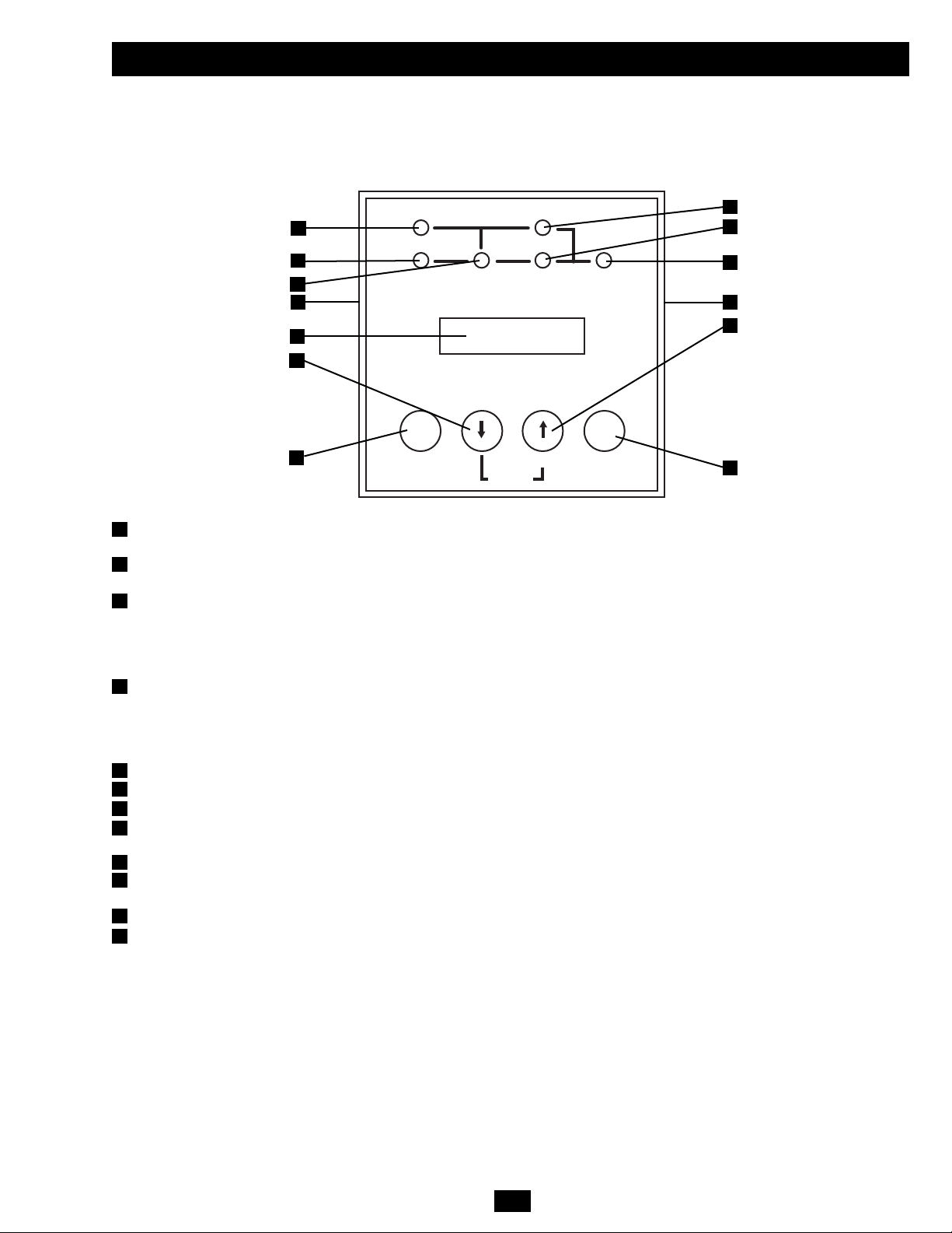
Front Control Panel
I/P BYPASS
BATTERY AC/DC DC/AC O/P
OFFON
MUTE SELECT
SETUP
LCD Display: This backlit dot matrix display indicates a wide range of UPS operating conditions and diagnostic data. It also displays
UPS settings and options when the UPS is in setup mode.
“ON/MUTE” Button: Press this button and hold it until you hear a beep to turn the UPS system's inverter ON. If the battery alarm is
sounding, press this button to silence it.
Scroll Down Button: This button allows you to browse through different options and power readings on the LCD display. Momentarily
pressing it causes the LCD screen to display a different power reading (see “Operation” section). Pressing it and the SCROLL UP Button
together puts the UPS in setup mode, where this button is used to scroll through setup options and to exit setup mode. Pressing the
SCROLL UP and SCROLL DOWN buttons simultaneously for longer than 1 second while the UPS is in “ON BATTERY MODE”
allows you to change the output voltage of the UPS (refer to “Output Voltage Selection” in the “Operation” section for details).
Scroll Up/“SELECT” Button: This button allows you to browse through different options and power readings on the LCD display.
Momentarily pressing it causes the LCD screen to display a different power reading (see “Operation” section). Pressing it and the
SCROLL DOWN Button together puts the UPS in setup mode, where this button is used to select setup options. Pressing the SCROLL
UP and SCROLL DOWN buttons simultaneously for longer than 1 second while the UPS is in “ON BATTERY MODE” allows you to
change the output voltage of the UPS (refer to “Output Voltage Selection” in the “Operation” section for details).
“OFF” Button: Press this button until you hear a beep to turn the UPS system's inverter OFF.
“O/P” (Output) LED: This green light will illuminate to indicate your UPS is supplying AC power to connected equipment.
“DC/AC” (Inverter) LED: This green light will illuminate to indicate the DC/AC inverter is activated.
“BYPASS” LED: This green light will illuminate when the UPS is providing filtered mains power without engaging its converter or
inverter. If this LED is lit, connected equipment will not receive battery power in the event of a blackout or other power interruption.
“AC/DC” (Converter) LED: This green light will illuminate to indicate the AC/DC converter is charging the connected battery pack(s).
“BATTERY” LED: This red light will illuminate when the UPS is discharging the battery to provide connected equipment with AC
power. An alarm will sound which can be silenced by pressing the ON/MUTE Button. This LED will remain lit after the alarm is silenced.
“I/P” (Input) LED: This green light will illuminate to indicate an AC input supply is present.
Control Panel Access Slots: The control panel can be adjusted to match the orientation of the UPS system. (1) Insert a flathead
screwdriver into the access slots and gently lever the control panel away from the front panel of the UPS system. (2) Rotate the control
panel to the desired orientation. DO NOT twist or pull the control panel cables excessively. (3) Gently reinsert the control panel into the
front panel of the UPS system.
1
2
3
4
5
6
7
8
9
10
11
12
1
2
3
4
5
6
7
8
9
10
11
12
12
Page 4
4
Features (continued)
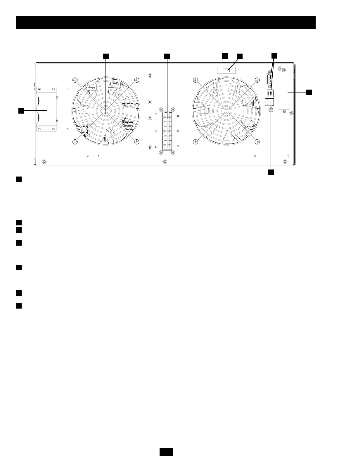
Power Module
This 4U module houses the UPS system's power and control components.
External Battery Connector: Use this connector to attach one or more Tripp Lite external battery packs to the power module. Remove
the retention bracket for access. The power module will not start without a connection to a charged, compatible battery pack. Check to
ensure that the external battery pack you are connecting matches the voltage listed next to the battery connector. Small sparks may result
during battery connection; this is normal. Do not connect or disconnect battery packs while the UPS is running on battery power (the
“BATTERY” LED will be lit on the control panel). Warning: Always use the connector retention brackets to secure the battery pack
connection (see the “Connection” section for instructions). Do not operate the UPS system without the connector retention brackets in
place. Refer to the battery pack owner's manual for additional connection instructions and safety warnings.
Ventilation Fans: These fans cool the interior of the power module.
Input/Output Terminal Block: These terminals connect the power module to the detachable PDU.
Warning: Do not contact the live terminals.
Battery Charge Level Switch: This switch controls the UPS system's battery charge rate. The switch is set to the left (the position
labeled “NORMAL”) by default. If you connect more than one external battery pack to the UPS system, set the Battery Charge Level
Switch to the right (the position labeled “HIGH”), allowing the additional batteries to charge faster. Warning: Setting the Battery Charge
Level Switch to “HIGH” when only one battery pack is connected may damage the battery pack.
Serial and USB Ports: These serial (RS-232 DB9) and USB ports enable optional connection of the UPS to corresponding ports on a
workstation or server. When the UPS system is connected to a computer via the included serial or USB cable, Tripp Lite's PowerAlert
Software can be used to monitor and control the UPS system. PowerAlert can also save files and shut down computers automatically
during extended power failures. (See “Optional Connection” section for more information.)
EPO Port: This port enables optional connection to a facility's EPO (Emergency Power Off) circuit for emergency shutdown of the UPS
inverter. (See “Optional Connection” section for more information.) Do not connect a telephone line to this port.
Accessory Slot: Remove the slot's cover to install an optional internal SNMP/Web accessory card (Model: SNMPWEBCARD) to enable
remote UPS monitoring and control via SNMP, Web or telnet. Call (773) 869-1234 or go to www.tripplite.com to learn about available
SNMP, network management and connectivity products.
1
2
3
4
5
6
7
1
2 3
2
4
5
6
7
Page 5
5
Features (continued)
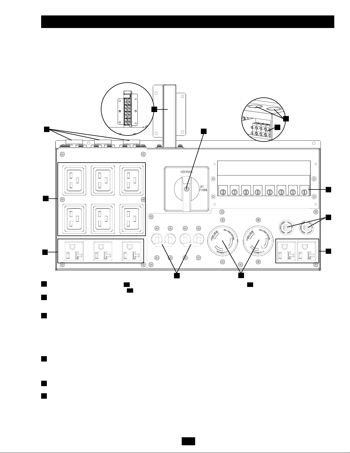
AC Output Receptacles (Outlets): These IEC-320-C19 outlets accept IEC-320-C20 plugs. These NEMA 5-15/20R outlets accept
NEMA 5-15P or NEMA 5-20P plugs. These NEMA L6-30R outlets accept NEMA L6-30P plugs.
AC Output Breakers: These breakers prevent the AC output receptacles from operating when they are overloaded. If the breakers trip
during an overload, they may be reset to continue normal operation after the overload has been corrected by removing excess equipment
loads.
Manual Bypass Switch: When this switch is set to BYPASS, qualified service personnel may detach the PDU to allow power module
maintenance, repair or replacement without interrupting the flow of power to connected equipment loads. Connected equipment will
receive unfiltered AC utility line power while the switch is set to BYPASS, but the equipment will not receive battery power in the event
of a power failure. See the "Manual Bypass Procedure" section for detailed manual bypass instructions, including important safety
warnings.
WARNING! The manual bypass switch is for use by qualified personnel only. Unless the complete bypass procedure is performed
correctly, the UPS will not be adequately powered down, presenting a risk of death or serious injury from contact with high voltage.
Utility Input Terminal Block: Use these terminals to connect the PDU to AC utility input power. To access the terminals, unscrew and
remove the terminal block cover. (Diagram shows cover removed.) The UPS must be connected to a dedicated circuit of sufficient
amperage, split-phase rated in accordance with the equipment nameplate and properly grounded. Connect the UPS system only to a fourwire input power connection (L1, L2, N, G). The UPS requires an input neutral connection.
Power Module Terminal Block: These terminals connect the PDU to the Power Module's corresponding Input/Output Terminal Block.
WARNING: Do not contact the live terminals.
Utility Input Terminal Block Cable Access: Route the AC utility input power cables through these knockouts in order to attach the
cables to the Utility Input Terminal Block.
8C
8B8A
8
9
10
11
12
13
Detachable Power Distribution Unit (PDU)
This independent, detachable PDU houses the UPS system's AC power input/output connections and a manual bypass switch. While the
manual bypass switch is set to BYPASS, the PDU can be removed from the power module for routine power module maintenance, repair or
replacement without interrupting the flow of power to connected equipment loads. Connected equipment will receive unfiltered AC utility
line power while the switch is set to BYPASS, but the equipment will not receive battery power in the event of a power failure. See the
“Manual Bypass Procedure” section for detailed manual bypass instructions. An optional PDU with hardwire output is also available from
Tripp Lite. Call (773) 869-1234 or go to www.tripplite.com for more information on available PDU options.
9
8A
8B
10
9
8C
8B
9
11
12
13
Reverse View
Top View
11
Page 6
6
Features (continued)
External Battery Pack Connectors: Use these connectors to connect the battery pack to the power module and to daisy-chain additional
Tripp Lite external battery packs with the main external battery pack for extended runtime. (Daisy-chaining additional battery packs is
optional.) Remove the retention bracket(s) for access (the diagram shows the upper bracket removed). Check to ensure that the external
battery pack you are connecting matches the voltage listed next to the battery connector. Small sparks may result during battery
connection; this is normal. Do not connect or disconnect battery packs while the UPS is running on battery power (the “BATTERY” LED
will be lit on the control panel). Warning: Always use the connector retention brackets to secure the battery pack connection (see the
“Connection” section for instructions). Do not operate the UPS system without the connector retention brackets in place.
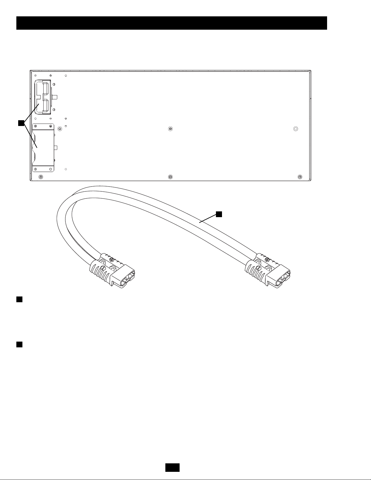
Battery Power Cable: Use this cable to connect the battery pack to the power module.
14
External Battery Pack with Detachable Power Cable
This 4U external battery pack houses the UPS system's batteries. Multiple battery packs can be daisy-chained to increase available battery
backup runtime for connected equipment during power failures. Refer to the battery pack owner's manual for connection instructions and
safety warnings.
15
14
15
Page 7
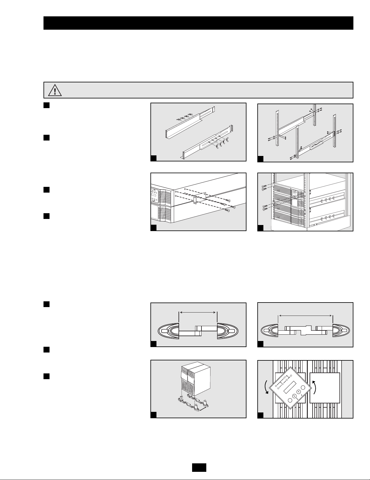
Mounting (4-Post Rackmount)
The UPS includes rackmount shelf kits for 4-post rackmounting. The user must determine the fitness of hardware and procedures before
mounting. If hardware and procedures are not suitable for your application, contact the manufacturer of your rack or rack enclosure. The
procedures described in this manual are for common rack and rack enclosure types and may not be appropriate for all applications.
WARNING! The UPS system is extremely heavy. Use caution when lifting and mounting. User must properly stabilize the UPS when
lifting and mounting. Note: The power module and battery module must be installed in separate shelves.
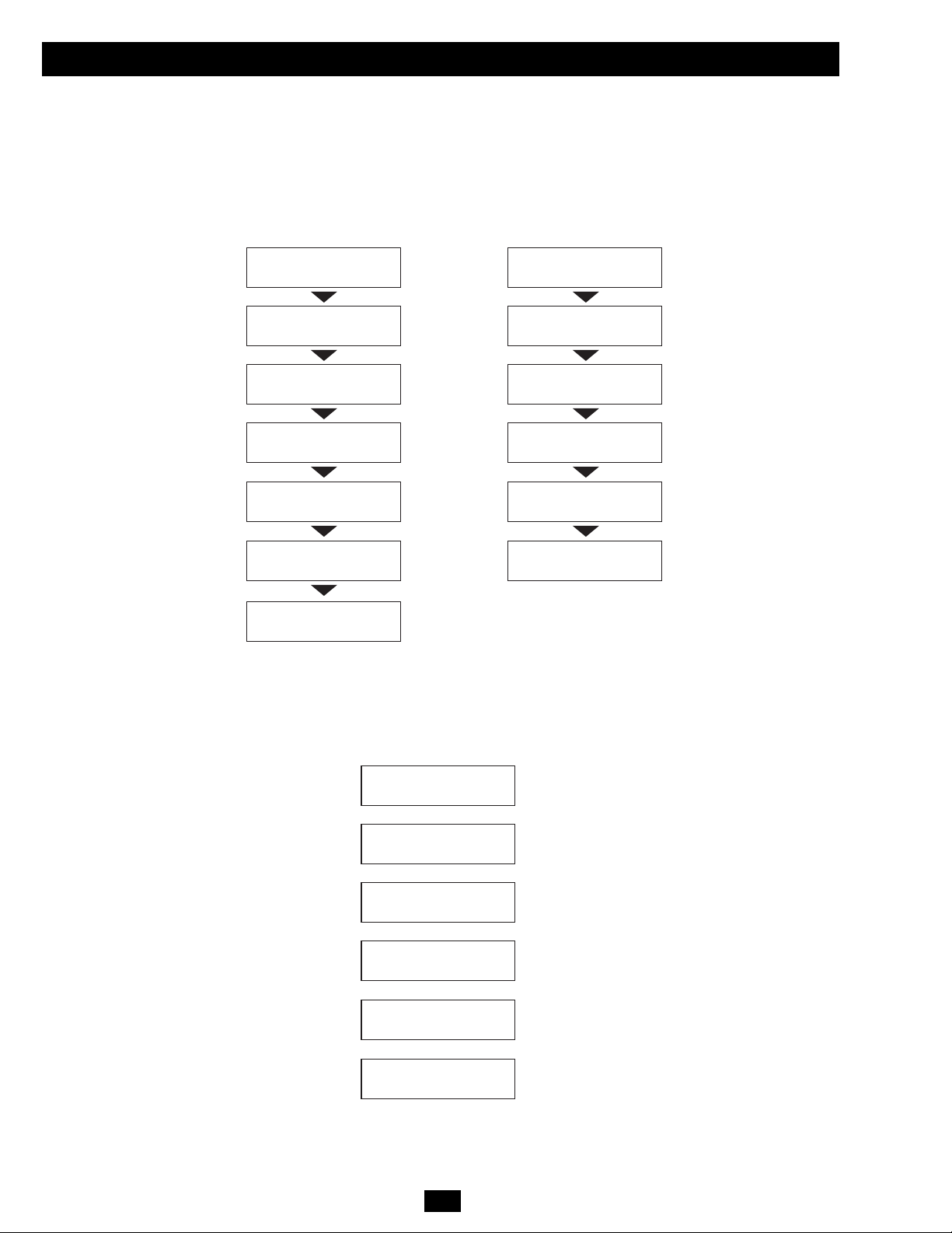
Connect the two segments of each shelf
using the included attached screws and
wing nuts. Leave the screws slightly
loose so that the shelves can be adjusted
in the next step.
Adjust each shelf to fit the rack, then
mount them in the lowest available
space of the rack (above the battery
pack) with the screws, nuts and washers
provided. Note that the support ledges
should face inward. Tighten the
wingnuts that connect the shelf
segments.
Attach mounting ears to the front
mounting holes of the UPS using the
screws provided. The ears should face
forward.
Using one or more assistants, lift the
UPS and slide it onto the mounting
shelves. Attach the UPS to the rack by
inserting the appropriate hardware
through the mounting ears and into the
rack rails.
7
Mounting
3
2
1
4
Mounting (Tower)
Mount the UPS system in a vertical, tower position using 2-9USTAND base stands (optional). The user must determine the fitness of hardware
and procedures before mounting.
WARNING! The UPS system is extremely heavy. Use caution when lifting and mounting. User must properly stabilize the UPS when
lifting and mounting.
Adjust the stands to a width of 6.93
inches (176 mm) for the power module.
Adjust the stands to a width of 13.86
inches (352 mm) for the power module
and external battery pack. Align the
stands approximately 10 inches
(254 mm) apart.
Have one or more assistants help you
place the UPS on its side in the stands.
Place the UPS so that its control panel is
on top and facing outward.
Rotate the control panel for easy
viewing while the UPS is mounted in
tower position. Insert a small tool in the
slots on either side of the control panel.
Gently lever the panel out; rotate it;
gently push the panel back into place.
1
3
I/P
BYPASS
BATTERY
AC/DC DC/AC
O/P
OFF
ON
MUTE
SELECT
SETUP
3
1
2
3
4
2
INSTALL THE 4U EXTERNAL BATTERY PACK BEFORE INSTALLING THE POWER MODULE. SEE THE
INCLUDED BATTERY PACK OWNER'S MANUAL FOR INSTRUCTIONS AND WARNINGS.
2
1 Power Module
6.93 in. (176 mm)
1 Power Module +
1 Battery Pack
13.86 in. (352 mm)
1
1
10 in.
(254 mm)
Page 8
8
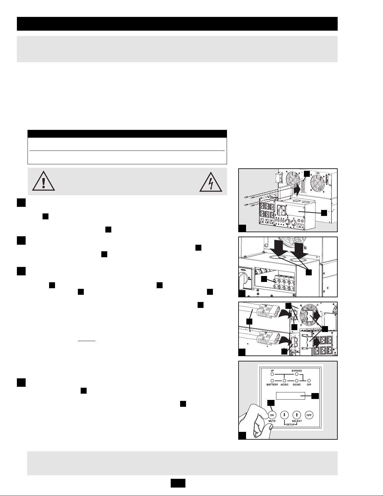
Connection
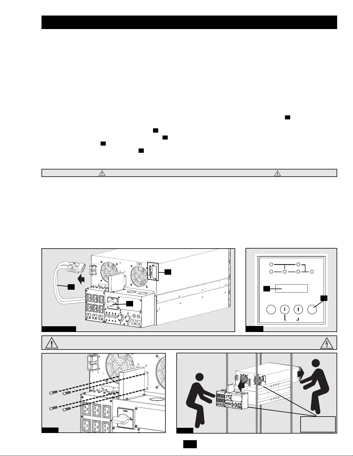
Attach the PDU to the Power Module and Battery Pack.
Align and connect the PDU's power module terminal block with the input/output terminal
block on the back of the power module. Secure the PDU to the power module with four
screws. Before proceeding, ensure that the bypass switch is set to NORMAL. Remove the
utility input terminal block cover .
Hardwire the PDU to a Utility Power Source.
Pass user-supplied cabling through the knockouts on the top of the PDU and connect
it to the PDU's input terminals . Replace the terminal block cover. Connect the other
end of the cabling to a dedicated utility power circuit of sufficient amperage.
Connect the Battery Pack to the Power Module.
Consult the owner’s manual that came with the battery pack. Remove the retention
brackets from the power module's battery connector and one of the battery pack's
rear panel connectors . Attach one end of the detachable battery power cable to each
connector. (Small sparks may occur; this is normal.) Reattach the retention brackets
immediately to the right of each connector, using the additional screw holes provided to
the right of the original bracket position. The brackets will secure the battery power cable
connection. Warning: Always use the connector retention brackets to secure the
battery pack connection. Do not attempt to operate the UPS system without the
connector retention brackets in place. NOTE: the power module does not contain
internal batteries and will not
start until a battery pack is connected. Allow the battery to
charge for at least 12 hours to ensure full battery backup for connected equipment. If you
require increased battery backup runtime, an unlimited number of additional external
battery packs may be daisy-chained to the primary battery pack. Adding additional external
battery packs will increase runtime battery backup runtime, but it will also increase
recharge time.
Turn the UPS On.
Press the “ON” Button until you hear a beep to begin inverter operation. The UPS will
now provide output power through its AC outlets to connected equipment. The UPS will
perform a brief self-test and show the results on the LCD Display . See “Startup SelfTest” in the “Operation” section for the display sequence.
Cold Start: To use the UPS as a stand-alone power source when AC input power is unavailable (i.e. during a
blackout), you can cold start the UPS and power connected equipment from the battery. The battery must be at least
partially charged for this operation to succeed. Press and hold the “ON” Button until you hear a beep to cold start
the UPS. The LCD Display will show “ON BATTERY MODE”. Battery power will begin discharging. Some
electronic equipment may draw more amps during startup; when cold starting, consider reducing the initial load on
the UPS.
K
J
I
HG
FE
D
C
B
A
1
2
J
K
4
Note: The output voltage is set at 208/120V~ when the UPS is shipped from the factory. If you need to change
the output voltage of the UPS, refer to “Output Voltage Selection” in the “Operation” section. You should select
the correct output voltage before connecting equipment to the UPS.
1
2
Hardwiring Cautions
• Wiring must be installed by a qualified electrician.
• When making wiring connections, observe the regulations appropriate to your region [National Electrical Code (NEC) in the U.S.] at all
times. Be sure to install an easily accessible disconnect switch in your installation wiring so you may cut off the UPS AC input during fires
and other emergencies. Ensure that cables are fitted with cable sleeves and are secured by connector clamps. Tighten connections with a
torque of not less than 24-28 inch-pounds (2.7-3.2 newton-meters). Make sure that your equipment is properly grounded.
• Using cables of improper size may damage your equipment and cause fire hazards. Choose appropriate cabling and protection circuits to
make wiring connections. Ground conductors must be the same size and type as the power conductors used.
• Refer to National Electrical Code (NEC) guidelines for proper wire gauge and output protection circuit requirements.
A
3
Contacts on Power Module and PDU
WARNING! High Voltage! Risk of electrical shock!
Do not let these contacts touch any surface!
See "Manual Bypass Procedure" section for more information.
4
3
B
C
D
F
E
G
H
I
Input and Output Ratings
Input Maximum Rated Maximum Rated Typical
Model Voltage Input Current Output Current Wire Size
SU16000RT4U 100-140V (L1-N: L2-N) 68A 70A 4 AWG
SU16000RT4UHW 100-140V (L1-N: L2-N) 68A 70A 4 AWG
To Turn the UPS System OFF: Press the UPS's “OFF” Button until you hear a beep. The UPS will stop providing output power through
its AC outlets. The LCD Display will show “STANDBY MODE.” The UPS will continue to charge its batteries as long as AC input
power is present. To completely deactivate the UPS, disconnect the UPS from AC input power when the UPS system is in standby mode.
Page 9
9
Optional Connection
The following connections are optional. The UPS system will function properly without these
connections.
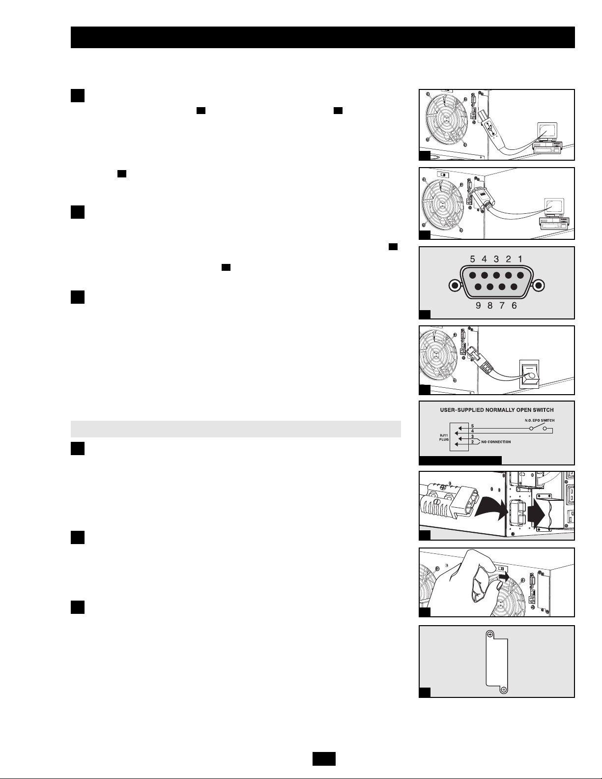
USB and Serial Communication Connection
Use the included USB cable and/or RS-232 DB9 serial cable to connect the
communication port of a computer to the communication port of the UPS. Install the
PowerAlert Software appropriate for the computer’s operating system. Consult the
PowerAlert manual for more information.
Dry Contact Note: Dry contact communications are simple, but some knowledge of
electronics is necessary to configure them. The DB9 port's pin assignments are shown in
diagram . If the UPS battery is low, the UPS sends a signal by bridging pins 1 and 5.
If utility power fails, the UPS sends a signal by bridging pins 8 and 5. To shut the UPS
down remotely, short pin 3 and pin 9 for at least 3.8 seconds.
EPO Port Connection
This optional feature is only for those applications that require connection to a facility's
Emergency Power Off (EPO) circuit. When the power module is connected to this circuit,
it enables emergency shutdown of the UPS system’s output. Using the included cable ,
connect the EPO port to a user-supplied normally open switch. The pin assignment for
the EPO port is shown in diagram . The EPO port is not a phone line surge
suppressor; do not connect a phone line to this port.
2b
2a
1c
1b1a
1
2
1a
1b
2a
2b EPO Pin Assignment
3a
3b
Additional Battery Pack Connection
The UPS system includes one external battery pack. Additional external battery packs are
not required to operate the UPS system, but they will provide additional battery backup
runtime for connected equipment.
Connect multiple battery packs by daisy-chaining the second to the first, daisy-chaining
the third to the second and so on. Note: When daisy-chaining multiple battery packs, they
should be identical models of similar age and level of wear. Make sure that cables are
inserted fully into connectors. Small sparks may occur during battery connection; this is
normal. Do not connect or disconnect battery packs when the UPS is operating from
battery power. Multiple battery packs provide longer runtimes, but also require longer
recharge times.
Additional Battery Pack Connection Procedure
(1) Remove the retention bracket from one of the first battery pack’s rear panel
connectors. (The other connector will already be attached to the power module or another
battery pack.) (2) Insert one end of the detachable power cable into each battery pack,
making sure to insert the cable connectors into the battery pack connectors fully. (3)
Attach the retention brackets to the right of each connector, using the screw holes set to
the right of the original bracket position. Warning: Always use the connector retention
brackets to secure the battery pack connections. Do not attempt to operate the UPS
system without the connector retention brackets in place.
If two or more external battery packs (including the external battery pack that is included
with the UPS system) are connected to the UPS system, move the Battery Charge Level
Switch from the default position (labeled “NORMAL”) to the right-hand position
(labeled “HIGH”). Warning: Setting the Battery Charge Level Switch to “HIGH” with
only one external battery pack connected to the UPS system may damage the external
battery pack.
Internal SNMP/WEB Card Insertion
Remove the slot's cover to install an optional internal SNMP/Web accessory card (Model:
SNMPWEBCARD) to enable remote UPS monitoring and control via SNMP, Web or
telnet. Contact Tripp Lite Customer Support at (773) 869-1234 for more information,
including a list of available SNMP, network management and connectivity products.
3
4
1c
4
3a
3b
Page 10
10
Operation
The user can enter the Setup Mode at anytime (except during the Diagnostic Mode) by pushing both scroll buttons at the same time for more
than 1 second. The Setup procedure is as follows:
Startup Self-Test
When you turn the UPS ON, it will enter Diagnostic Mode and perform a self-test lasting about 15 seconds. The results of the self-test are
shown on the LCD screen in the sequences below.
Failed Self-Test
If a problem is detected during the self-test, the LCD will display an error message. If your UPS displays any of the following messages in its
LCD, call Tripp Lite Technical Support at (773) 869-1234 for service.
LCD Screen Message Sequence
(If UPS Is Started with AC Input)
DIAGNOSTIC MODE
FREQ OUT = XXHz
DIAGNOSTIC MODE
INPUT AC OK
DIAGNOSTIC MODE
BATTERY OK
DIAGNOSTIC MODE
CHARGER OK
DIAGNOSTIC MODE
AC/DC OK
DIAGNOSTIC MODE
TESTING INVERTER
UPS MODE
LOAD1 = XXX% X.XKW
LCD Screen Message Sequence
(If UPS Is “Cold-Started” with No AC Input)
DIAGNOSTIC MODE
FREQ OUT = XXHz
DIAGNOSTIC MODE
INPUT AC BAD
DIAGNOSTIC MODE
BATTERY OK
DIAGNOSTIC MODE
AC/DC OK
DIAGNOSTIC MODE
TESTING INVERTER
ON BATTERY MODE
LOAD1 = XXX% X.XKW
LCD Screen Messages
(If UPS Fails Self-Test)
BAD BATTERY!
CALL FOR SERVICE
CHARGER FAILURE!
CALL FOR SERVICE
AC/DC FAILURE!
CALL FOR SERVICE
INVERTER FAILURE!
CALL FOR SERVICE
OUTPUT FAILURE!
CALL FOR SERVICE
FAN FAILURE!
CALL FOR SERVICE
Page 11
11
Operation (continued)
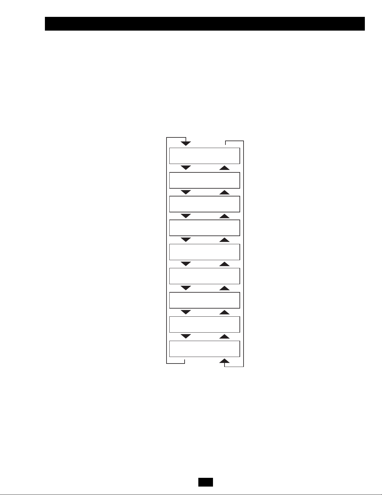
Normal Operation
During normal operation, the first line of your LCD Display shows which operating mode your UPS is in: “UPS MODE”, “ON BATTERY
MODE”, “BYPASS MODE” or “STANDBY MODE”.
“UPS MODE”: The UPS provides AC power while utility power is available and switches to ON BATTERY MODE instantly (zero transfer
time) if AC power is interrupted.
“ON BATTERY MODE”: The UPS provides AC power from battery backup so long as battery power lasts. It switches back to UPS MODE
if utility power is available and shuts down if it runs out of battery power.
“STANDBY MODE”: The UPS is plugged in, charging its batteries and receiving AC power. However, it has not been turned on.
“BYPASS MODE”: The UPS provides AC power while utility power is available. The UPS shuts down if AC power is interrupted.
The second line of the LCD Display shows basic power conditions. Push the SCROLL buttons to browse through these basic power conditions
in the sequence shown below.
On Battery Alarm
When in ON BATTERY MODE, the UPS power module will beep to inform you that it is using battery power to support connected equipment.
If its connected batteries are at more than half capacity, it will beep every two seconds. If its connected batteries are below half capacity, it
will beep twice per second. If its connected batteries are nearly depleted, the UPS power module will beep continuously. To silence the On
Battery Alarm, press the “ON/MUTE” Button.
XXXX MODE
LOAD1 = XXX% X.XKW
XXXX MODE
LOAD2 = XXX% X.XKW
XXXX MODE
IN = XXXV XX.X Hz
XXXX MODE
IN1 = XXXV XX.X Hz
XXXX MODE
IN2 = XXXV XX.X Hz
XXXX MODE
OUT = XXXV XX.X Hz
XXXX MODE
OUT1 = XXXV XX.X Hz
XXXX MODE
OUT2 = XXXV XX.X Hz
XXXX MODE
BATT = XXXVDC XXX%
Page 12
12
Operation (continued)
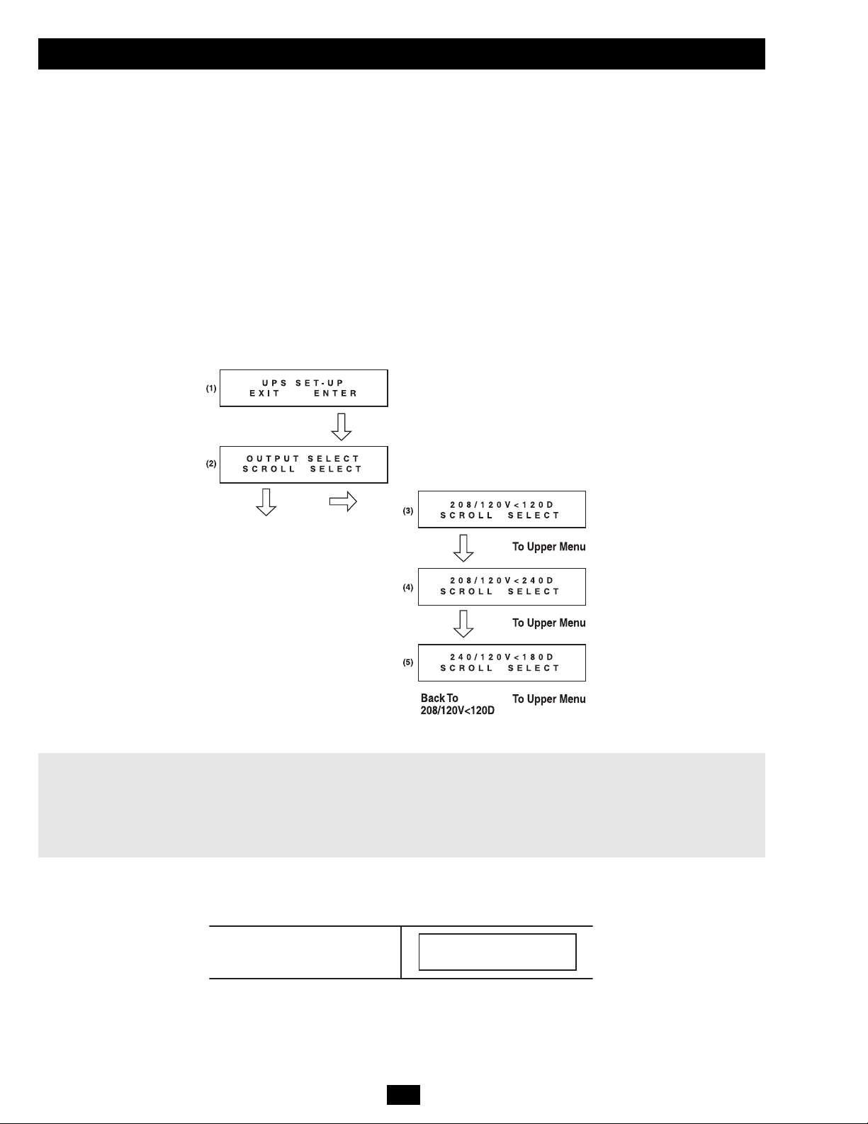
Output Voltage Selection
The UPS output voltage is set at 208/120V~ when the UPS is shipped from the factory. In order to change the output voltage of the UPS, you
first need to enter “ON BATTERY MODE” by cold-starting the UPS. (The battery must be at least partially charged for this operation to
succeed.) If the UPS is on, press and hold the “OFF” button until you hear a beep, disconnect any connected equipment and disconnect the
UPS from its AC power input. After the UPS is disconnected from AC power, press the “ON/MUTE” button until you hear a beep. The LCD
screen will show “ON BATTERY MODE” and an alarm will sound periodically to inform you that the UPS is using battery power. Silence
the alarm by pressing the “ON/MUTE” button.
After the UPS has entered “ON BATTERY MODE”, press the SCROLL UP and SCROLL DOWN buttons simultaneously for longer than
1 second. The UPS will beep and the LCD will show the SET-UP screen (1). Press the SCROLL UP/SELECT button to enter the “UPS SET-UP”
procedure (2). Press the SCROLL UP/SELECT button again to enter the “OUTPUT SELECT” procedure (3). There are 3 output voltage
selections. Press the SCROLL DOWN button to scroll to the desired output voltage selection (3)-(5) and then press the SCROLL UP/SELECT
button to select it. The LCD will return to the “OUTPUT SELECT” screen (2). Press the SCROLL DOWN button to reach the SET-UP screen
(1) and press the SCROLL DOWN button again to exit the SET-UP procedure. The LCD should be back to “ON BATTERY MODE”. Press
the “OFF” key until you hear a beep, and the UPS will save the selected output voltage parameter. Restore the AC power input of the UPS and
press the “ON” key to turn on the UPS and use the SCROLL DOWN button to scroll through the basic power conditions displays and confirm
that the output voltage has been changed to the desired value.
Note:
208 / 120V<120D Output Voltage (L1-L2)=208V, Output Voltage (L1,L2)=120V and L1 leads L2 120 degrees
208 / 120V<240D Output Voltage (L1-L2)=208V, Output Voltage (L1,L2)=120V and L2 leads L1 120 degrees
240 / 120V<180D Output Voltage (L1-L2)=240V, Output Voltage (L1,L2)=120V and L1 leads L2 180 degrees
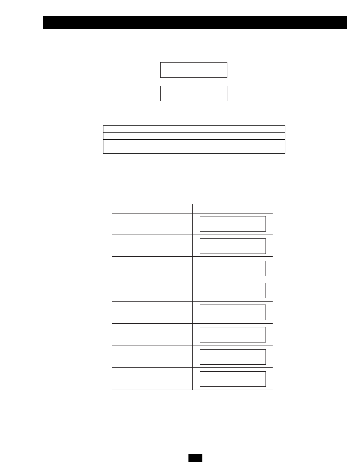
Additional Self-Test
If a self-test is initiated after startup, the LCD will display a message.
Self-Test Is Running
TESTING BATTERY
LOAD1 = XXX% X.XKW
Page 13
13
Operation (continued)
The UPS will then begin a countdown. If the UPS is still overloaded at the end of the countdown, the UPS will automatically go to BYPASS
MODE to protect its inverter. The duration of the countdown varies with the severity of the overload, as follows:
Overload Condition Countdown Duration
102% - 125% 1 minute
125% - 150% 30 seconds
> 150% Immediate Bypass
Bypass Messages
While in BYPASS MODE, the UPS monitors its input voltage and passes that input power along to connected equipment. The UPS will not
provide battery backup in BYPASS MODE. If the output voltage deviates from an acceptable range (between 15% higher and 20% lower than
nominal), the UPS displays the condition on its LCD and stops supplying output power to its load. If power levels return to an acceptable level,
the UPS resumes supplying power to the load, and its LCD reports that output voltage was too high or too low at one time, but has returned
to nominal.
Overload Messages
When the UPS detects an output overload, its LCD will switch to the following display:
OVERLOAD!
LOAD1 = XXX% X.XKW
OVERLOAD!
LOAD2 = XXX% X.XKW
Bypass Voltage Conditions
LCD Screen Messages
L1 > 15% Higher
Than Nominal Voltage
L2 > 15% Higher
Than Nominal Voltage
L1 > 20% Lower
Than Nominal Voltage
L2 > 20% Lower
Than Nominal Voltage
L1 Voltage Was Too High,
Now Returned to Nominal Voltage
L2 Voltage Was Too High,
Now Returned to Nominal Voltage
L1 Voltage Was Too Low,
Now Returned to Nominal Voltage
L2 Voltage Was Too Low,
Now Returned to Nominal Voltage
BYPASS AC1 HIGH
LOAD1 = XXX% X.XKW
BYPASS AC2 HIGH
LOAD1 = XXX% X.XKW
BYPASS AC1 LOW
LOAD1 = XXX% X.XKW
BYPASS AC2 LOW
LOAD1 = XXX% X.XKW
BYPASS AC1 WAS HI
LOAD1 = XXX% X.XKW
BYPASS AC2 WAS HI
LOAD1 = XXX% X.XKW
BYPASS AC1 WAS LO
LOAD1 = XXX% X.XKW
BYPASS AC2 WAS LO
LOAD1 = XXX% X.XKW
Page 14

14
Operation (continued)
Shutdown Messages
Your UPS will shut down and the LCD will display a message if it detects one of the following conditions. Note: During all these conditions,
the “Input,” “Output” and “Bypass” LEDs will be illuminated.
Shutdown Conditions
L1 Extended Overload
L2 Extended Overload
L1 to L2
Output Short Circuit
L1 to N Output Short Circuit
L2 to N Output Short Circuit
Remote Shutdown Command
(via DB9)
Remote Shutdown Command
(via EPO)
Battery Depletion
Site Wiring Fault
EEPROM Failure
Positive DC BUS Voltage
is Too High
Positive DC BUS Voltage
is Too Low
Negative DC BUS Voltage
is Too High
Negative DC BUS Voltage
is Too Low
Fan Failure
UPS Overtemperature
L1 Inverter Too High
L1 Inverter Too Low
SHUTDOWN
L1 O VERLOAD=XXX%
LCD Screen Messages
SHUTDOWN
L2 O VERLOAD=XXX%
OP S HORTCIRCUIT
LOAD1 = XX X% X. XKW
OP1 SHORTCIRCUIT
LOAD1 = XX X% X. XKW
OP2 SHORTCIRCUIT
LOAD1 = XX X% X. XKW
REMOTE C OMMAND
LOAD1 = XX X% X. XKW
EMERGENCY STO P!
LOAD1 = XX X% X. XKW
SITE WIR ING F AULT
LOAD1 = XX X% X. XKW
EEPROM FAI L
LOAD1 = XX X% X. XKW
+DC BUS HIGH
LOAD1 = XX X% X. XKW
+DC BUS LOW
LOAD1 = XX X% X. XKW
-DC BUS HIGH
LOAD1 = XX X% X. XKW
-DC BUS LOW
LOAD1 = XX X% X. XKW
FAN FAIL
LOAD1 = XX X% X. XKW
OVERTEMPERATURE
LOAD1 = XX X% X. XKW
LOW BATTERY
LOAD1 = XX X% X. XKW
INVERTER1 HIG H
LOAD1 = XX X% X. XKW
INVERTER1 LOW
LOAD1 = XX X% X. XKW
L2 Inverter Too High
L2 Inverter Too Low
INVERTER2 HIG H
LOAD1 = XX X% X. XKW
INVERTER2 LOW
LOAD1 = XX X% X. XKW
Shutdown Conditions
Internal Charger Failure
External Charger Failure
Battery Open / Bad Battery
Phase Lock Failure,
Bypass Lockout
Phase Lock Failure,
Inverter Lockout
LCD Screen Messages
INT CHARGER F AIL
LOAD1 = XX X% X. XKW
EXT CHARGER F AIL
LOAD1 = XX X% X. XKW
BAD BATTERY!
LOAD1 = XX X% X. XKW
BYPASS LOC KOUT
LOAD1 = XX X% X. XKW
INVERTER LOCK OUT
LOAD1 = XX X% X. XKW
Page 15
15
Manual Bypass Procedure
WARNING! For qualified service personnel only. Failure to follow the bypass procedure completely will not adequately power down
the UPS, resulting in the continued risk of death or injury from potential contact with high voltage. The UPS is extremely heavy. This
procedure requires several people to perform.
The UPS system includes an independent, detachable PDU with a bypass switch. This switch allows qualified service personnel to remove the
detachable PDU from the power module for maintenance, repair or replacement without disrupting power to connected loads. While this
switch is set to “BYPASS”, connected equipment will receive unfiltered AC mains power, but the equipment will not receive battery power in
the event of a blackout.
Note: An optional hardwire output detachable PDU is also available. Contact Tripp Lite for details.
UPS Power Module Removal
STEP 1. Disable PowerAlert Software and disconnect all communication cable(s) from the communication port(s) on the UPS
power module.
STEP 2. Turn the detachable PDU's Bypass Switch to “BYPASS”.
STEP 3. If the UPS is powered, press the “OFF” button until you hear a beep and see a “STANDBY MODE” message shown in
the LCD Display .
STEP 4. Disconnect the battery power cable from the UPS power module.
The UPS power module is now safely powered down and it can be detached from the PDU to perform maintenance/replacement.
STEP 5. Remove the screws that hold the detachable PDU to the power module.
STEP 6. Using several assistants at each end, carefully pull the detachable PDU away from the power module. During this process,
ensure that each section is properly supported after they are separated.
• If the sections are detached in a rackmount application, ensure that each section remains adequately supported by the
rackmount rails. Remove the rackmounting hardware from the front panel of the UPS; slide the power module forward, and
remove. The PDU will remain supported on the rackmount rails. Care should be taken in this process because the PDU will
not be secured to the rack with hardware of any kind.
• If the sections are detached in a tower application, ensure that the PDU is supported by the UPS's tower feet. Adjust the tower
feet so they are as close together as possible.
Warning: Use extreme caution when handling the PDU. Do not allow the contacts to touch any surface.
To reattach the PDU, reverse the process listed above.
E
D
C
B
A
Steps 1, 2 & 4
Step 3
E
B
A
D
C
Step 5
Step 6
WARNING! High Voltage! Risk of electrical shock! SEE NEXT PAGE.
See warning
statements on
next page!
WARNING! High Voltage! Risk of electrical shock! SEE NEXT PAGE.
I/P BYPASS
BATTERY AC/DC DC/AC O/P
MUTE SELECT
OFFON
SETUP
Page 16
16
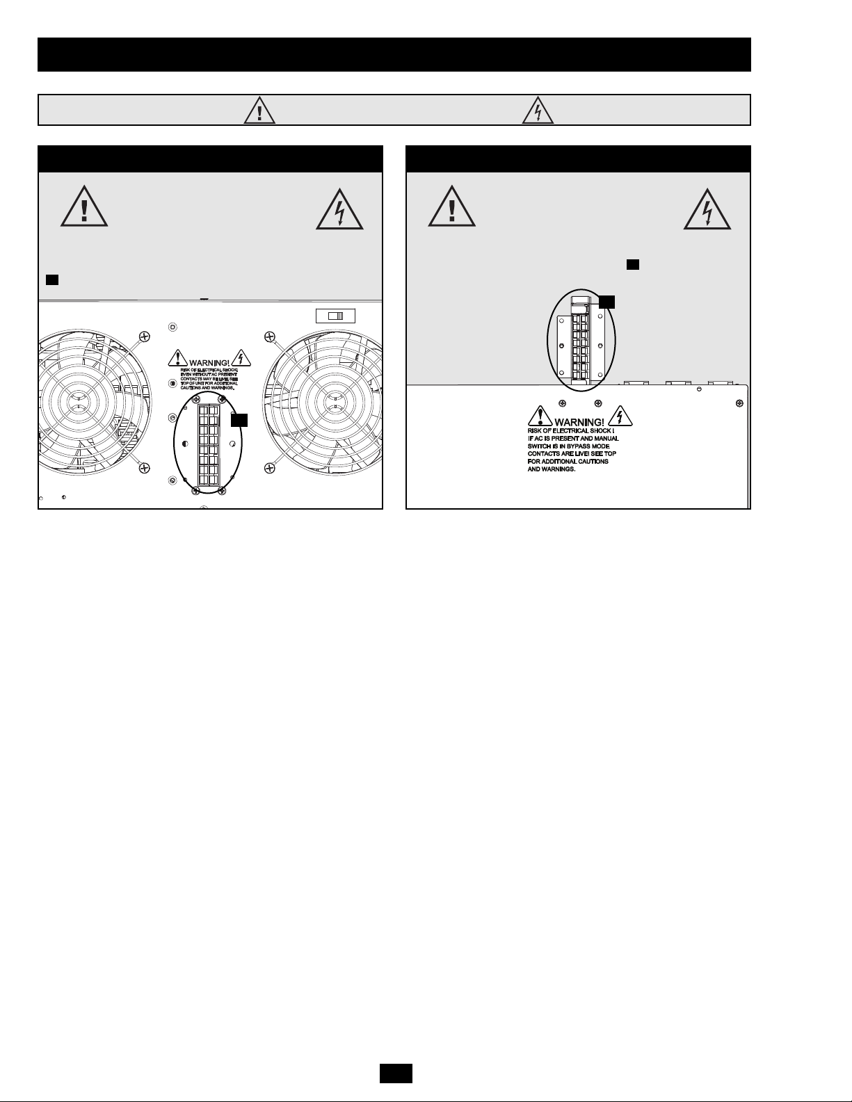
High Voltage Warnings
Contacts on Power Module
WARNING!
High Voltage!
Risk of electrical shock!
When the external battery pack is connected to the
power module, even without AC present, these contacts
are live! Do not let these contacts touch any surface!
A
Contacts on Detachable PDU
WARNING!
High voltage!
Risk of electrical shock!
If AC is present and Bypass Switch is set to
“Bypass”, these contacts are live!
Do not let these contacts touch any surface!
B
A
B
Manual Bypass Procedure (continued)
Page 17

17
Storage
Before storing your UPS, turn it completely OFF. If you store your UPS for an extended period of time, recharge the UPS batteries for 4 to 6
hours once every three months. Note: after you connect the UPS to utility power, it will automatically begin charging its batteries. If you leave
your UPS batteries discharged for an extended period of time, they will suffer a permanent loss of capacity.
Service
Your SmartOnline UPS is covered by a 2-year limited warranty. Avariety of Extended Warranty and On-Site Service Programs are also available
from Tripp Lite. For more information on service, call Tripp Lite Customer Support at (773) 869-1234.
Before returning your UPS for service, follow these steps:
1. Review the installation and operation instructions in this manual to ensure that the service problem does not originate from a misreading of
the instructions.
2. If the problem continues, do not contact or return the UPS to the dealer. Instead, call Tripp Lite at (773) 869-1233. A service technician will
ask for the UPS's model number, serial number and purchase date and will attempt to correct the problem over the phone.
3. If the problem requires service, the technician will issue you a Returned Material Authorization (RMA) number, which is required for
service. They will also discuss proper packaging and shipping procedures. Any damages (direct, indirect, special, incidental or consequential)
to the UPS incurred during shipment to Tripp Lite or an authorized Tripp Lite service center is not covered under warranty. UPS Systems
shipped to Tripp Lite or an authorized Tripp Lite service center must have transportation charges prepaid. Mark the RMA number on the
outside of the package. If the UPS System is within the 2-year warranty period, enclose a copy of your sales receipt. Return the UPS for service
using an insured carrier to the address given to you by the Tripp Lite service technician.
Tripp Lite has a policy of continuous improvement. Specifications are subject to change without notice.
FCC Radio/TV Interference Notice:
Note: This equipment has been tested and found to comply with the limits for a Class Adigital
device, pursuant to Part 15 of the FCC Rules. These limits are designed to provide
reasonable protection against harmful interference when operated in a commercial
environment. This equipment generates, uses and can radiate radio frequency energy, and if
not installed and used in accordance with the instruction manual, may cause interference to
radio communications. Operation of this equipment is likely to cause harmful interference in
which case the user will be required to correct the interference at their own expense. The user
must use shielded cables and connectors with this product. Any changes or modifications to
this product not expressly approved by the party responsible for compliance could void the
user's authority to operate the equipment.
Made in China.
Regulatory Compliance
Identification Numbers
For the purpose of regulatory compliance certifications and identification, your Tripp Lite
product has been assigned a unique series number. The series number can be found on the
product nameplate label, along with all required approval markings and information. When
requesting compliance information for this product, always refer to the series number. The
series number should not be confused with the marking name or model number of the
product.
Warranty
2-YEAR LIMITED WARRANTY
Seller warrants this product, if used in accordance with all applicable instructions, to be free from original defects in material and workmanship for a period of 2 years (except internal UPS system
batteries outside USA and Canada, 1 year) from the date of initial purchase. If the product should prove defective in material or workmanship within that period, Seller will repair or replace the
product, in its sole discretion. Service under this Warranty can only be obtained by your delivering or shipping the product (with all shipping or delivery charges prepaid) to: Tripp Lite; 1111 W.
35th Street; Chicago IL 60609; USA. Seller will pay return shipping charges. Call Tripp Lite Customer Service at (773) 869-1234 before sending any equipment back for repair.
THIS WARRANTY DOES NOTAPPLY TO NORMAL WEAR OR TO DAMAGE RESULTING FROM ACCIDENT, MISUSE, ABUSE OR NEGLECT. SELLER MAKES NO EXPRESS WARRANTIES
OTHER THAN THE WARRANTY EXPRESSLY SET FORTH HEREIN. EXCEPT TO THE EXTENT PROHIBITED BY APPLICABLE LAW, ALL IMPLIED WARRANTIES, INCLUDING ALL
WARRANTIES OF MERCHANTABILITY OR FITNESS, ARE LIMITED IN DURATION TO THE WARRANTY PERIOD SET FORTH ABOVE; AND THIS WARRANTY EXPRESSLY EXCLUDES
ALL INCIDENTAL AND CONSEQUENTIAL DAMAGES. (Some states do not allow limitations on how long an implied warranty lasts, and some states do not allow the exclusion or limitation of
incidental or consequential damages, so the above limitations or exclusions may not apply to you. This Warranty gives you specific legal rights, and you may have other rights which vary from
jurisdiction to jurisdiction).
Tripp Lite; 1111 W. 35th Street; Chicago IL 60609; USA
WARNING: The individual user should take care to determine prior to use whether this device is suitable, adequate or safe for the use intended. Since individual applications are subject to great
variation, the manufacturer makes no representation or warranty as to the suitability or fitness of these devices for any specific application.
Visit www.tripplite.com/warranty today to register the warranty for your new Tripp Lite product. You'll be automatically entered into a drawing
for a chance to win a FREE Tripp Lite product!*
* No purchase necessary. Void where prohibited. Some restrictions apply. See website for details.
Warranty Registration
1111 W. 35th Street, Chicago, IL 60609 USA
(773) 869-1234
Page 18

18
Manual del Propietario
Sistemas UPS SmartOnline
™
Modular Hot-Swappable
Modelos: SU16000RT4U y SU16000RT4UHW
Instrucciones de Seguridad Importantes
19
Características
20
Montaje
24
Conexión
25
Conexión Opcional
26
Procedimiento de Derivación Manual
32
Operación
27
Almacenaje y Servicio
33
Garantía
34
1111 W. 35th Street, Chicago, IL 60609 USA
+1 773 869 1234
Derechos de Autor © 2008 Tripp Lite. Todos los derechos reservados. SmartOnline™ es una marca registrada de Tripp Lite.
English
1
Français
35
No es apropiado para aplicaciones Móviles
Page 19

19
Instrucciones de Seguridad Importantes
CONSERVE ESTAS INSTRUCCIONES. Este manual contiene instrucciones y advertencias que deberán
ser seguidas durante la instalación y mantenimiento de este Sistema UPS. El Manual del Propietario del
módulo de baterías también contiene instrucciones y advertencias importantes. Lea el Manual del
Propietario del módulo de baterías antes de tratar de instalar el Sistema UPS.
Advertencias Sobre la Ubicación del UPS
• El UPS es extremadamente pesado. Extreme las precauciones cuando lo levante e instale.
• Instale el UPS al interior, lejos del exceso de humedad o calor, luz solar directa , polvo y conductores contaminantes,
• Instale el UPS en un área estructuralmente sólida.
• Opere el UPS únicamente a temperaturas en el interior entre 32º F y 104º F (0º C y 40º C). Para mejores resultados mantenga la temperatura
en el interior entre 62° F y 84° F (entre 17° C y 29° C).
• Deje un espacio adecuado alrededor de todos los lados del UPS para una ventilación apropiada. No Obstruya los ventiladores ni las aberturas.
• No instale el UPS cerca de medios de almacenaje magnéticos ya que esto puede resultar en corrupción de la información.
• Si está instalando el UPS en una configuración de columna apilable, siempre coloque el módulo de potencia arriba del (los) módulo(s) de batería(s).
• No instale la unidad con el panel delantero o trasera hacia abajo (en ningún ángulo). Montándolo de esta manera inhibirá seriamente el
enfriamiento interno de la unidad, causando finalmente daño al equipo que no está cubierto por la garantía.
Advertencias para Conectar el UPS
• La fuente de energía para esta unidad debe estar calificada como de fase dividida [split-phase] de acuerdo a la placa de identificación del equipo.
También deberá estar conectado adecuadamente a tierra..
• Conecte el sistema UPS únicamente a una conexión de entrada de corriente de cuatro hilos (L1, L2, N, G). Este UPS requiere una conexión de
entrada neutral.
• Conecte el UPS a una fuente de entrada CA correctamente conectada a tierra. No modifique la conexión de entrada de ninguna manera que pueda
eliminar la conexión a tierra.
• No utilice adaptadores que eliminen la conexión a tierra.
• No conecte la entrada del UPS a su propia salida, esto dañará al UPS y anulará la garantía.
• Si está conectando el UPS a un generador CA, operado por un motor, el generador debe suministrar una salida filtrada, con frecuencia regulada
con calidad para computadora. Conectar el UPS a un generador anulará su garantía de por vida..
Advertencias para Conectar el Equipo
• El uso de este equipo en aplicaciones de soporte de vida en donde la falla de este equipo pueda hacer suponer que causará la falla del equipo de
soporte de vida o significativamente afectar su seguridad o efectividad no es recomendado. No use este equipo en presencia de una mezcla
anestésica inflamable con aire, oxigeno u oxido nitroso.
• El UPS está conectado a una fuente de energía CD (La batería). Las terminales de Salida pueden estar vivas aun si el UPS no está conectado a una
fuente de energía CA.
• No conecte supresores de sobretensión o extensiones a la salida de corriente del UPS. Esto puede sobre cargar al UPS y anulará las garantías del
supresor de sobretensión y del UPS.
Advertencias de Mantenimiento
• El UPS no requiere mantenimiento de rutina. No abra el UPS por ningún motivo. No hay partes útiles para el usuario en su interior.
Advertencias sobre la Batería
• No opere el UPS sin haber conectado el módulo de potencia a un módulo de baterías externas..
• Conecte únicamente módulos de baterías Tripp Lite a los conectores de las baterías. Conecte módulos de baterías del voltaje y tipo correcto.
• Las baterías internas en el módulo de baterías son reciclables . Refiérase a las regulaciones locales para los requerimientos de disposición
y destrucción de las baterías, o en los Estados Unidos llame al 800-SAV-LEAD (800-728-5323) o al 800-8-BATTERY (800-822-8837),
o vaya al sitio www.rbrc.com para obtener información completa acerca del proceso de reciclado. PRECAUCION: No arroje las baterías al fuego ,
ya que esto puede hacer que las baterías exploten.
• Debido a que las baterías presentan un riesgo de descargas eléctricas y quemaduras de corriente de fuertes corto circuito. El remplazo de la batería
debe ser llevado a cabo personal de servicio debidamente entrenado que observe las precauciones adecuadas. Quítese relojes, anillos y cualquier
otro objeto de metal. Utilice herramientas con mangos o empuñaduras aislantes. Use guantes de hule y botas. No deje herramientas o partes de metal
encima de la baterías. No ponga las terminales de la batería en corto circuito ni las puentee con ningún objeto. Desconecte la fuente de carga antes
de conectar o desconectar las terminales de la batería. Determine si las baterías están inadvertidamente conectadas a tierra. Si están inadvertidamente
conectadas a tierra, remueva la fuente de la conexión a tierra. El contacto con cualquier parte de una batería conectada a tierra puede resultar en
una descarga eléctrica. La probabilidad de tal descarga se reducirá si esas conexiones a tierra se retiran durante la instalación y mantenimiento.
• No abra o mutile las baterías. El electrolito liberado es dañino para la piel y los ojos y puede ser tóxico.
• Los Fusibles deberán ser remplazados únicamente por personal autorizado de fabrica. Los fusibles quemados/fundidos se deberán remplazar
específicamente por fusibles del mismo número y tipo.
• El servicio y reparación deberá ser efectuado únicamente por personal debidamente capacitado. Durante cualquier servicio y reparación al UPS,
éste deberá apagarse o puesto en modo de derivación manual (Vea Procedimiento para Derivación Manual). Nota: Voltaje potencialmente
letal existe dentro de esta unidad, en tanto el suministro de energía de la batería esté conectado.
• No conecte o desconecte los módulos de baterías externas mientras el UPS este operando con el suministro de la batería.
• Durante el remplazo "hot-swap" de la batería, el UPS no proveerá energía de respaldo en el caso de un apagón u otro tipo de interrupciones del
Page 20

20
Características
El sistema UPS incluye un módulo de potencia, un módulo de baterías externas y un PDU independiente y desmontable con un interruptor de
derivación manual. Cuando el interruptor se pone en derivación, el PDU puede removerse totalmente del módulo de potencia para mantenimiento,
reparación o remplazo del módulo de potencia sin interrumpir la corriente a las cargas conectadas. Revise la ubicación y funciones de las características
del sistema UPS antes de instalarlo y de operarlo.
Controles en el Panel Frontal
I/P BYPASS
BATTERY AC/DC DC/AC O/P
OFFON
MUTE SELECT
SETUP
Pantalla LCD: Esta pantalla retro iluminada, de matriz de punto, muestra un gran rango de información acerca de las condiciones de operación
y diagnóstico del UPS. También despliega los parámetros y opciones del UPS cuando el UPS está en modo de instalación.
Botón "ON/MUTE" [Encendido/Silencio]: Presione este botón y manténgalo así hasta que escuche un pitido para encender el inversor del
sistema UPS. Si la alarma de la batería está sonando, presione este botón para apagarla.
Botón Scroll Down [Recorrido Hacia Abajo]: Este botón le permite navegar por diferentes opciones e información de energía en la pantalla
LCD. Presionándolo momentáneamente hace que la pantalla LCD muestre diferentes lecturas de la energía (vea la sección Operación).
Presionado simultáneamente este botón y el botón SCROLL UP [Recorrido Hacia Arriba] pone al UPS en modo de configuración, en donde este
botón es usado para recorrer las diferentes opciones de configuración y salir del modo de configuración. Presionado simultáneamente el botón
SCROLL UP [Recorrido Hacia Arriba] y el botón SCROLL DOWN [Recorrido Hacia Abajo] durante más de 1 segundo mientras el UPS esta en
"ON BATTERY MODE" [En Respaldo] le permite cambiar el voltaje de salida del UPS (refiérase a Selección de Voltaje de Salida en la sección
Operación para obtener más detalles).
Botón Scroll Up/"SELECT" [Recorrido Hacia Arriba/Seleccione]: Este botón le permite navegar por diferentes opciones e información
de energía en la pantalla LCD. Presionándolo momentáneamente hace que la pantalla LCD muestre diferentes lecturas de la energía (vea la
sección Operación). Presionado simultáneamente este botón y el botón SCROLL DOWN [Recorrido Hacia Abajo] pone al UPS en modo de
configuración, en donde este botón es usado para seleccionar las opciones de configuración. Presionado simultáneamente el botón SCROLL UP
[Recorrido Hacia Arriba] y el botón SCROLL DOWN [Recorrido Hacia Abajo] durante más de 1 segundo mientras el UPS esta en "ON BATTERY
MODE" [En Respaldo] le permite cambiar el voltaje de salida del UPS (refiérase a Selección de Voltaje de Salida en la sección Operación para
obtener más detalles).
Botón "OFF" [Apagado]: Presione este botón hasta que escuche un pitido para apagar el inversor del UPS.
LED "O/P" (Output) [Salida]: Esta luz verde se iluminará para indicar que su UPS está suministrando energía CA al equipo conectado.
LED "DC/AC" (Inverter) [CD/CA (Inversor)]: Esta luz verde se iluminará para indicar que el inversor CD/CA está activado.
LED "BYPASS" [Derivación]: Esta luz verde se iluminará cuando el UPS está suministrando energía filtrada de la fuente principal sin activar
su convertidor o su inversor. Si este LED está iluminado, el equipo conectado no tendrá respaldo de la batería en el caso de un apagón o de
cualquier otro tipo de interrupción de energía.
LED "AC/DC" (Converter) [CA/DC (Convertidor): Esta luz verde se iluminará para indicar que el convertidor CA/CD está cargando al
módulo de baterías conectado.
LED "BATTERY" [Batería]: Esta luz roja se iluminará cuando la batería del UPS se está descargando por suministrar al equipo conectado
energía CA. sonará una alarma que se puede apagar presionando el botón ON/MUTE [Encendido/Silencio]. Este LED permanecerá encendido
después que la alarma haya sido apagada.
LED "I/P" (Input) [Entrada]: Esta luz verde se iluminará para indicar que un suministro CA está presente.
Ranura de Acceso del Panel de Control: El panel de control puede ajustarse para coincidir con la orientación del sistema UPS. (1) Inserte un
desarmador plano en las ranuras de acceso y suavemente levante el panel de control del panel frontal del sistema UPS. (2) Gire el control en la
orientación deseada. NO tuerza o jale los cables del panel de control excesivamente. (3) Con delicadeza reinserte el panel de control en el panel
frontal del sistema UPS.
1
2
3
4
5
6
7
8
9
10
11
12
1
2
3
4
5
6
7
8
9
10
11
12
12
Page 21

21
Características (continuación)
Módulo de Potencia
Este módulo 4U contiene los componentes de potencia y control del sistema UPS.
Conector de la Batería Externa: Use este conector para conectar uno o más módulos de baterías externas al módulo de potencia. Remueva las
abrazaderas de retención para tener acceso. El módulo de potencia no arrancará sin una conexión a un módulo de baterías compatible y cargado.
Revise para asegurarse que el módulo de baterías externas que está conectando es del voltaje indicado junto al conector de la batería. Pueden
presentarse algunas chispas pequeñas durante la conexión de la batería; esto es normal. No conecte o desconecte módulos de baterías externas
cuando el UPS este operando con energía de la batería (El LED "BATTERY"[Batería] estará encendido en el panel de control). Advertencia:
siempre use las abrazaderas de retención para asegurar la conexión del módulo de baterías (Vea la sección Conexión para más instrucciones).
No opere el sistema UPS sin las abrazaderas de retención del conector en su lugar. Refiérase al manual del propietario del módulo de baterías
por instrucciones de conexión adicionales y advertencias de seguridad.
Ventiladores: Estos ventiladores enfrían el interior del módulo de potencia.
Bloque Terminal de Entrada /Salida: Estas terminales conectan el módulo de potencia al PDU desmontable.
Advertencia: No haga contacto con las terminales vivas.
Interruptor del Nivel de Carga de la Batería: Este interruptor controla el promedio de carga de la batería del sistema UPS. El interruptor viene
de fábrica colocado hacia la izquierda (la posición marcada "NORMAL"). Si conecta más de un módulo de baterías externas al sistema UPS,
coloque el Interruptor del Nivel de Carga de la Batería hacía la derecha (la posición marcada "HIGH"[Alta]), permitiendo de esta forma que las
baterías se carguen más rápido. Advertencia: Colocando el Interruptor del Nivel de Carga de la Batería en "HIGH" [Alta] cuando solo un
módulo de baterías está conectado puede dañar al módulo de baterías.
Puertos Serial y USB: Estos puertos serial (RS-232 DB9) y USB permiten conexiones opcionales del UPS a los puertos correspondientes de un
servidor o estación de trabajo. Cuando el sistema UPS está conectado a una computadora con el cable serial o USB incluido, puede usarse para el
programa PowerAlert para controlar y monitorear el sistema UPS. PowerAlert puede salvar los archivos y apagar la computadora
automáticamente durante fallas prolongadas de la corriente. vea la sección Conexión Opcional para más información).
Puerto EPO: Este puerto permite la conexión opcional al circuito EPO (Emergency Power Off) [Apagado de Emergencia] para un apagado de
emergencia del inversor del UPS. (Vea la sección Conexión Opcional para más información). No conecte una línea telefónica a este puerto.
Ranura para Accesorios: Quite la tapa de la ranura para instalar la tarjeta interna SNMP/Web interna (Modelo: SNMPWEBCARD) para poder
controlar y monitorear en forma remota el UPS vía SNMP, Web o telnet. Lame al +1 773 869 1234 o visite el sitio www.tripplite.com para
obtener más información de productos SNMP, administración de redes y conectividad disponibles.
1
2
3
4
5
6
7
1
2 3
2
4
5
6
7
Page 22

22
Características (continuación)
Tomas de Corriente AC (Salidas): Estas tomas de corriente IEC-320-C19 aceptan clavijas IEC-320-C20. Estas tomas de corriente
NEMA 5-15/20R aceptan clavijas NEMA 5-15P o NEMA 5-20P. Estas tomas de corriente NEMA L6-30R aceptan clavijas NEMA L6-30P.
Interruptores de Circuito de la Salida CA: Estos interruptores de circuito evitan que las salidas CA operen cuando están sobrecargados. Si lis
interruptores de circuito se disparan durante una sobrecarga, pueden restablecerse para continuar con la operación normal después de que se haya
corregido la sobrecarga removiendo los equipos con cargas excesivas.
Interruptor de Derivación Manual: Cuando este interruptor se coloca en BYPASS [Derivación], el personal de servicio calificado puede
remover el PDU para permitir dar mantenimiento, reparar o remplazar el módulo de potencia sin interrumpir el flujo de la corriente a los equipos
conectados. El equipo conectado recibirá energía del servicio público sin filtrar en tanto el interruptor permanezca en BYPASS [Derivación, pero
el equipo no recibirá respaldo de la batería en el caso de una falla de energía. Vea la sección Procedimiento de Derivación Manual para
instrucciones detalladas de la derivación manual, incluyendo importantes advertencias de seguridad.
¡ADERTENCIA! El interruptor de derivación manual es únicamente para uso de personal calificado. Ha no ser que el procedimiento de
derivación manual haya sido efectuado correctamente, la corriente del UPS no habrá sido cortada adecuadamente, lo que representa un
serio riesgo de muerte o una seria lesión por contacto con alto voltaje.
Bloque de Terminales de Entrada de Corriente del Servicio Público: Use estas terminales para conectar el PDU a la entrada CA del servicio
público. Para acceder a las terminales, desatornille y quite la tapa del bloque de terminales. (El diagrama se muestra sin la tapa) El UPS debe
estar conectado a un circuito dedicado con el suficiente amperaje, calificado fase dividida [split-phase] de acuerdo a la placa de identificación
del equipo y adecuadamente conectado a tierra. Conecte el sistema UPS únicamente a una conexión de entrada de corriente de cuatro hilos
(L1, L2, N, G). El UPS requiere una conexión de entrada neutral.
Bloque de Terminales del Módulo de Potencia: Estas terminales conectan al PDU a las correspondientes Bloque de Terminales de Entrada/Salida
del Módulo de Potencia. ADVERTENCIA: No permita que hagan contacto las terminales vivas.
Acceso de los cables al Bloque de Terminales de Entrada de Corriente del Servicio Público: Introduzca los cables de entrada de corriente del
servicio público por estas perforaciones [knockouts] para conectar los cables al Bloque de Terminales de Entrada de Corriente del Servicio Público .
8C
8B8A
8
9
10
11
12
13
Unidad de Distribución de Energía (PDU) Desmontable
Este PDU desmontable, independiente contiene las conexiones de entrada/salida CA del sistema UPS y el interruptor de derivación manual. En tanto
el interruptor de derivación manual esté colocado en BYPASS [Derivación], el PDU puede ser removido del módulo de potencia para
mantenimiento de rutina , reparación o reemplazo del módulo de potencia sin interrumpir el flujo de la corriente a las cargas conectadas. El
equipo conectado recibirá energía sin filtrar del servicio público en tanto el interruptor está colocado en BYPASS [Derivación] pero el equipo no
recibirá energía de la batería en el caso de una falla de energía del servicio público. Vea la sección Procedimiento de Derivación Manual para
instrucciones detalladas de la derivación manual. También hay un PDU opcional con salida hardwire que está disponible en Tripp Lite. Llame al
+1 773 869 1234 o vaya al sitio www.tripplite.com para obtener más información para opciones de PDU disponibles.
9
8A
8B
10
9
8C
8B
9
11
12
13
Vista Dorsal
Vista Superior
11
Page 23

23
Características (Continuación)
Conectores del Módulo de Baterías Externas: Use estos conectores para conectar el módulo de baterías al módulo de potencia y encadenar (en
Margarita) módulos de baterías externas Tripp Lite adicionales con el módulos de baterías externas principal para tiempo de respaldo extendido.
(Encadenar -en Margarita- módulos de baterías adicionales es opcional.) Remueva las abrazaderas de retención para tener acceso (el diagrama
muestra la abrazadera de retención superior removida). Revise para asegurarse que el módulo de baterías externas que está conectando tenga el
mismo voltaje que el que se indica al lado del conector de la batería. Pequeñas chispas pueden presentarse durante la conexión de la batería, esto
es normal. No conecte o desconecte los módulos de baterías mientras el UPS este trabajando con energía de la batería (el LED "BATTERY"
[Batería]) se encenderá en el panel de control. Advertencia: Siempre use las abrazaderas de retención del conector para asegurar la conexión del
módulo de baterías (vea la sección Conexión para instrucciones) No opere el sistema UPS sin las abrazaderas de retención del conector en su lugar.
Cable de Corriente de la Batería: Use este cable para conectar el módulo de baterías al módulo de potencia.
14
Módulo de Baterías Externas con Cable Desprendible
Este módulo de baterías externas 4U contiene las baterías del sistema UPS. Varios módulos de baterías externas pueden encadenarse (en Margarita)
para aumentar el tiempo de respaldo disponible para el equipo conectado durante fallas de la energía. Refiérase al manual del propietario del módulo
de baterías para instrucciones sobre la conexión y advertencias de seguridad.
15
14
15
Page 24

24
Montaje (Bastidor de 4 Postes)
El UPS incluye un juego de rieles de montaje para su instalación en un bastidor 4U. El usuario debe determinar la resistencia e idoneidad del hardware
y los procedimientos antes de montarlo. Si el hardware o los procedimientos no son los adecuados para su aplicación, comuníquese con el fabricante
de su bastidor o estante para bastidor. Los procedimientos descritos en este manual son para los tipos de bastidor y estantes para bastidores comunes
y puede que no sean apropiados para todas las aplicaciones.
¡ADVERTENCIA! El sistema UPS es extremadamente pesado. Tome las precauciones adecuadas cuando lo levante y lo instale. El usuario de estabilizar adecuadamente el UPS al levantarlo y montarlo. Nota: El módulo de potencia y el módulo de baterías deben ser instalados en rieles separados.
Una los dos segmentos de cada soporte de
montaje utilizando los tornillos y tuercas
de mariposa incluidos. Deje los tornillos
ligeramente sueltos de tal forma que los
rieles de montaje puedan ser ajustados en
el siguiente paso.
Ajuste cada soporte de montaje para que
encajen en el bastidor, a continuación fije
los rieles de montaje en el espacio
disponible más abajo (arriba del módulo de
baterías) con los tornillos, rondanas y
tuercas suministrados. Observe que los
bordes de los rieles deben orientarse hacia
adentro. Apriete las tuercas de mariposa que
unen los segmentos de los rieles de montaje.
Fije las orejas de montaje en las perforaciones para montaje delanteras del UPS
con las tuercas suministradas Las orejas
del soporte montaje deben orientarse hacia
delante.
Con la ayuda de uno o más asistentes,
levante el UPS y deslícelo sobre los rieles
de montaje. Fije el UPS al bastidor
insertando los tornillos y tuercas apropiados
a través de las orejas del soporte montaje en
los rieles/postes del bastidor.
Montaje
3
2
1
4
Montaje (Torre)
Instale el sistema UPS en una posición de torre, utilizando las bases 2-9USTAND (opcionales). El usuario debe determinar la resistencia e idoneidad
del hardware y los procedimientos antes de montarlo.
¡ADVERTENCIA! El sistema UPS es extremadamente pesado. Tome las precauciones adecuadas cuando lo levante y lo instale. El usuario de
estabilizar adecuadamente el UPS al levantarlo y montarlo.
Ajuste las bases a un ancho de 6.93
pulgadas (176 mm) para el módulo de
potencia Ajuste las bases a un ancho de
13.86 pulgadas (352 mm) para el módulo de
potencia y el módulo de baterías externas.
Alinee las bases con una separación de
aproximadamente 10 pulgadas (254 mm).
Con la ayudad de uno o más asistentes
coloque el UPS en las bases. Coloque el
UPS de tal modo que el panel de control
este arriba y viendo hacia afuera.
Gire el panel de control de forma que
pueda verse fácilmente con el UPS
instalado en torre. Inserte una herramienta
pequeña en las ranuras de cualquiera de
los lados del panel de control. Suavemente
haga palanca hasta sacar el panel, gírelo y
suavemente reinsértelo en su lugar.
1
3
1 Módulo de Potencia
6.93 in. (176 mm)
1 Módulo de Potencia +
1 Módulo de Baterías
13.86 in. (352 mm)
1
1
I/P
BYPASS
BATTERY
AC/DC DC/AC
O/P
OFF
ON
MUTE
SELECT
SETUP
3
1
2
3
4
2
INSTALE EL MODULO DE BATERIAS EXTERNAS 4U ANTES DE INSTALAR EL MODULO DE POTENCIA. VEA EL MANUAL
DEL PROPIETARIO DEL MODULO DE BATERIAS, INCLUIDO, PARA INFORMARSE DE INSTRUCCIONES Y ADVERTENCIAS.
2
10 in.
(254 mm)
Page 25

25
Conexión
Fije y Conecte el PDU al Módulo de Potencia y al
Módulo de Baterías.
Alinee y conecte el bloque de terminales del módulo de potencia del PDU con el bloque de
terminales de entrada/salida. en la parte posterior del módulo de potencia. Asegure el PDU
al módulo de potencia con cuatro tuercas. Antes de proseguir, asegúrese que el interruptor de
derivación está colocado en NORMAL. Remueva la tapa del bloque de terminales de la entrada
de corriente del servicio público .
Conecte Directamente [Hardwire] el PDU a un Fuente de
Energía del servicio Público.
Pase los cables, suministrados por el usuario, a través de los knockouts [perforaciones] en la
parte superior del PDU y conéctelos a la terminales de entrada del PDU . Vuelva a
colocar la tapa del bloque de terminales. Conecte el otro extremo de los cables a un circuito
dedicado para la energía del servicio público con suficiente amperaje.
Conecte el Módulo de Baterías al Módulo de Potencia.
Consulte el manual del propietario que viene con el módulo de baterías. Remueva las
abrazaderas de retención del conector de la batería del módulo de potencia y uno de los
conectores del panel trasero del módulo de la batería . Conecte un extremo del cable de
corriente, desprendible, de la batería a cada conector. (Pueden presentarse pequeñas chispas,
esto es normal.) Inmediatamente vuelva a colocar las abrazaderas de retención a la derecha de
cada conector, usando las perforaciones adicionales. que se encuentran a la derecha de la
posición original de las abrazaderas. Las abrazaderas asegurarán la conexión del cable de
corriente de la batería. Advertencia: Siempre use las abrazaderas de retención del conector
para asegurar la conexión del módulo de baterías. No trate de operar el sistema UPS sin
las abrazaderas de retención del conector en su lugar. NOTA: el módulo de potencia no
contiene baterías internas y no arrancará
hasta que un módulo de baterías esté conectado.
Permita que la batería se cargue por lo menos 12 horas para garantizar un respaldo completo al
equipo conectado. Si requiere aumentar el tiempo de respaldo, un número ilimitado de baterías
externas adicionales pueden encadenarse en margarita al módulo de baterías primario.
Aumentando módulos de baterías externas adicionales se incrementará el tiempo de respaldo
pero también aumentará el tiempo de recarga.
Encienda el UPS.
Presione el botón “ON” [Encendido] hasta que escuche un pitido para iniciar la operación
del inversor. El UPS suministrará corriente por sus salidas CA a todo el equipo conectado. El
UPS efectuará una breve auto-prueba y mostrará los resultados en la pantalla LCD . Vea Auto
Prueba de Arranque en la sección Operación para la secuencia de despliegue.
Arranque en Frío: Para usar el UPS como una fuente de energía autónoma cuando la energía CA de entrada no está
disponible (i.e. durante un apagón), puede arrancar el UPS en frío y suministrar corriente desde la batería al equipo
conectado. La batería deberá estar por lo menos parcialmente cargada para que esta operación tenga éxito. Presione el
botón “ON” [Encendido] hasta que escuche un pitido para arrancar en frío el UPS. La pantalla LCD mostrará “ON
BATTERY MODE” [En modo de Respaldo]. La batería comenzará a descargarse. Algunos equipos electrónicos puede
consumir más amperes durante el arranque, cuando arranque en frío considere el reducir la carga conectada al UPS.
K
J
I
H
G
FE
DC
B
A
1
2
J
K
4
Nota: El voltaje de salida es ajustado de fábrica a 208/120V~. Si necesita cambiar el voltaje de salida del UPS , refiérase a Selección
de Voltaje de Salida en la sección Operación. Debe seleccionar la salida de voltaje correcta antes de conectar cualquier equipo al UPS.
1
2
Precauciones para Efectuar la Instalación Eléctrica Fija [Hardwiring]
• El cableado eléctrico debe ser instalado por un electricista calificado.
• Cuando haga las conexiones del cableado, observe todo el tiempo las regulaciones apropiadas a su región [National Electrical Code (NEC) en los
EEUU]. Asegúrese de instalar un interruptor de desconexión de fácil acceso en la instalación de forma que pueda cortar la entrada CA del UPS en el
caso de un incendio u otras emergencias. Asegúrese que los cables cuentan con forros aislantes y están asegurados con abrazaderas de conexión. Apriete
las conexiones con una torsión no menor a 24-28pulgadas-libra (2.7-3.2 Newton-Metros) Asegúrese que su equipo está correctamente conectado a tierra.
• Utilizar cables de un calibre no adecuado puede dañar su equipo y causar incendios. Seleccione los cables y circuitos de protección adecuados para
hacer las conexiones. Los conductores a tierra deben ser del mismo calibre y tipo que el de los usados en los conductores de corriente.
• Refiérase a las guías de la National Electrical Code (NEC) para obtener los requerimientos de los calibres del cableado y la protección del circuito
de salida adecuado.
A
3
Contactos en el módulo de Potencia y el PDU
¡ADVERTENCIA! ¡Alto Voltaje! ¡Riesgo de descargas eléctricas!
¡No permita que estos contactos toquen ninguna superficie!
Vea la sección "Procedimiento de Derivación Manual" para mayor información.
4
3
B
C
D
F
E
G
H
I
Valores Nominales de Entrada y Salida
Voltaje de Corriente de entrada Corriente de salida Tamaño típico
Modelo entrada nominal máxima nominal máxima del alambre
SU16000RT4U 100-140V (L1-N: L2-N) 68A 70A 4 AWG
SU16000RT4UHW 100-140V (L1-N: L2-N) 68A 70A 4 AWG
Para Apagar el Sistema UPS: Presione el botón “OFF” [Apagado] del UPS hasta que escuche un pitido. El UPS dejará de suministrar corriente
de salida por sus salidas CA. La pantalla LCD mostrará “STANDBY MODE” [Modo en Espera]. El UPS continuará cargando sus baterías en tanto
haya energía de entrada presente. Para desactivar completamente el UPS, desconecte el UPS de la entrada CA cuando el UPS este en modo de espera.
Page 26

26
Conexión Opcional
Las siguientes conexiones son opcionales. El sistema UPS funcionará correctamente sin estas
conexiones.
Conexión de Comunicaciones USB y Serial
Use el cable USB y/o el cable serial RS-232 DB9 incluidos para conectar el puerto de
comunicaciones de una computadora al puerto de comunicaciones del UPS. Instale el Software
PowerAlert apropiado para el sistema operativo de la computadora. Consulte el manual de
PowerAlert para más información.
Nota sobre el Contacto Seco: Las comunicaciones del contacto seco son simples pero algún
conocimiento en electrónica es necesario para configurarlos. Las asignaciones de los pins
[patillas] del puerto DB9 se muestran en el diagrama . Si la batería del UPS está baja el UPS
envía una señal puenteando los pins [patillas] 1 y 5. Si la energía del servicio público falla el
UPS manda una señal puenteando los pins [patillas] 8 y 5. Para apagar el UPS en forma
remota, cortocircuite pin 3 y pin 9 por al menos 3.8 segundos.
Conexión del Puerto EPO
Esta característica opcional es únicamente para aquellas aplicaciones que requieren conectarse
a un circuito de Apagado de Emergencia. (EPO). Cuando el módulo de potencia está conectada
a este circuito, permite apagado de emergencia de la salida del sistema UPS. Utilizando el
cable incluido , conecte el puerto EPO a un interruptor normalmente abierto, suministrado
por el usuario. Las asignaciones de los pins [patillas] para el puerto EPO se muestran en el
diagrama . El puerto EPO no es un supresor de sobre tensiones para línea telefónica,
no conecte una línea telefónica a este puerto.
2b
2a
1c
1b1a
1
2
1a
1b
2a
2b Asignación del Pin EPO
3a
3b
Conexión del Módulo de Baterías Adicional
El sistema UPS incluye un módulo de batería externas. No se requieren módulos de baterías
externas adicionales para operar el sistema UPS pero si brindarán tiempo de respaldo adicional
al equipo conectado.
Conecte varios módulos de baterías externas encadenándolos –en margarita- el segundo al
primero, el tercero al segundo y así sucesivamente. Nota: Cuando encadene –en margarita-
varios módulos de baterías externas, éstos deberán ser modelos idénticos de edad y nivel de
usos similares. Asegúrese que los cables están completamente insertados en los conectores. Se
pueden presentar pequeñas chispas durante la conexión de la batería, esto es normal. No
conecte o desconecte módulos de baterías cuando el UPS esté operando con energía de la
batería. Varios módulos de baterías suministran tiempos de respaldo más prolongados pero
también requieren un mayor tiempo de recarga.
Procedimiento para conectar Módulos de Baterías
Adicionales.
(1) Remueva la abrazadera de retención de uno de los conectores en el panel trasero del primer
módulo de baterías (El otro conector ya estará conectado al módulo de potencia o a otro
módulo de baterías) (2) Inserte un extremo del cable de corriente desprendible en cada módulo
de batería, asegurándose de insertar los conectores del cable totalmente en los conectores de
la batería. (3) fije las abrazaderas de retención a la derecha de cada conector, utilizando las
perforaciones par los tornillos a la derecha de la posición original de la abrazadera.
Advertencia: Siempre use las abrazaderas de retención del conector para asegurar las
conexiones del módulo de baterías. No trate de operar el sistema UPS sin las abrazaderas de
retención en su lugar.
Si dos o más módulos de baterías externas (incluyendo el módulo de baterías externas que
incluido con el sistema UPS) están conectadas al sistema UPS, mueva el interruptor de nivel
de carga de la batería de su posición original de fábrica (marcada “NORMAL”) hacia la
posición a la derecha (marcada “HIGH” [Alta]). Advertencia: Colocando el Interruptor de
Nivel de Carga de la Batería en “HIGH” [Alta] con solo un módulo de baterías externas
conectado al sistema UPS puede dañar el módulo de baterías externas.
Inserción de la Tarjeta Interna SNMP/WEB
Remueva la tapa de la ranura para instalar una tarjeta interna, opcional, SNMP/Web (Modelo:
SNMPWEBCARD) para habilitar el monitoreo y control remoto del UPS vía SNMP, Web o
telnet. Contacte el Servicio a clientes de Tripp Lite al +1 773 869 1234 para más información,
incluyendo una lista de productos SNMP, administración de redes y conectividad disponibles.
3
4
1c
4
3a
3b
INTERRUPTOR NORMALMENTE CERRADO
(SUMINISTRADO POR EL USUARIO
CLAVIJA
RJ11
SIN CONEXIÓN
NTERRUPTOR N.C. EPO
Page 27

27
Operación
El usuario puede entrar al modo de instalación en cualquier momento (excepto durante el modo de diagnóstico) presionando los dos botones de
recorrido al mismo tiempo durante más de 1 segundo. El procedimiento de instalación es como sigue:
Auto Prueba de Arranque
Ciando enciende el UPS, éste entra en Modo de Diagnóstico y efectuará una auto prueba que dura aproximadamente 15 segundos. Los resultados de
la auto prueba se muestran en la pantalla LCD en la secuencia indicada a continuación.
DIAGNOSTIC MODE
FREQ OUT = XXHz
Secuencia de Mensajes en la Pantalla LCD
(Si el UPS Arranca con Entrada CA)
DIAGNOSTIC MODE
FREQ OUT = XXHz
Secuencia de Mensajes en la Pantalla
(Si el UPS Arranca en Frío sin Entrada
DIAGNOSTIC MODE
INPUT AC OK
DIAGNOSTIC MODE
INPUT AC BAD
DIAGNOSTIC MODE
BATTERY OK
DIAGNOSTIC MODE
BATTERY OK
DIAGNOSTIC MODE
CHARGER OK
DIAGNOSTIC MODE
AC/DC OK
DIAGNOSTIC MODE
AC/DC OK
DIAGNOSTIC MODE
TESTING INVERTER
DIAGNOSTIC MODE
TESTING INVERTER
UPS MODE
LOAD1 = XXX% X.XKW
ON BATTERY MODE
LOAD1 = XXX% X.XKW
Auto Prueba Fallida
Si se detecta algún problema durante la auto prueba, la pantalla LCD mostrará un mensaje de error. Si su UPS despliega cualquiera de los siguientes
mensajes en la pantalla LCD, llame al Servicio Técnico de Tripp Lite al +1 773 869 1234 para servicio.
Mensajes en la Pantalla LCD
(Si el UPS Falla su Auto Prueba)
BAD BATTERY!
CALL FOR SERVICE
CHARGER FAILURE!
CALL FOR SERVICE
AC/DC FAILURE!
CALL FOR SERVICE
INVERTER FAILURE!
CALL FOR SERVICE
OUTPUT FAILURE!
CALL FOR SERVICE
FAN FAILURE!
CALL FOR SERVICE
Page 28

28
Operación (continuación)
Operación Normal
Durante la operación normal, la primera línea de su pantalla LCD en que modo de operación está su UPS : “UPS MODE” [Modo UPS], “ON
BATTERY MODE” [Modo de Respaldo], “BYPASS MODE” [Modo de Derivación] o “STANDBY MODE” [Modo de Espera].
“UPS MODE” [Modo UPS]: El UPS suministra energía CA en tanto la energía del servicio público esté disponible y cambia ON BATTERY MODE
[Modo de Respaldo] instantáneamente (cero tiempo de transferencia)si la energía CA es interrumpida.
“ON BATTERY MODE” [MODO DE RESPALDO]: El UPS suministra energía CA de la batería por el tiempo que dure la carga de la batería.
Regresa a UPS MODE [Modo UPS] si hay energía del energía del servicio público disponible y se apaga si se agota la carga de la batería.
“STANDBY MODE” [MODO DE ESPERA]: El UPS está enchufado, cargando sus baterías y recibiendo energía CA. Sin embargo, no se ha
encendido.
“BYPASS MODE” [MODO DE DERIVACIÓN]: El UPS suministra energía CAmientras la energía del servicio público esté disponible. El UPS se
apaga si la energía CA es interrumpida.
La segunda línea de la pantalla LCD muestra las condiciones básicas de la energía. Presione los botones de recorrido para navegar por estas condiciones
de energía básicas en la secuencia mostrada a continuación.
Alarma de Modo de Respaldo
Cuando está en ON BATTERY MODE [Modo de Respaldo], El módulo de potencia del UPS pitará par informarle que esta usando le energía de la
batería para respaldar al equipo conectado. Si sus baterías tienen más de la mitad de su capacidad, pitará cada dos segundos. Si sus baterías tienen
menos de la mitad de su capacidad, pitará dos veces por segundo. Si sus baterías están casi agotadas, el módulo de potencia del UPS pitará de forma
continua. Para apagar la alarma del modo de respaldo [On Battery], presione el botón “ON/MUTE” [Encendido/Silencio].
XXXX MODE
LOAD1 = XXX% X.XKW
XXXX MODE
LOAD2 = XXX% X.XKW
XXXX MODE
IN = XXXV XX.X Hz
XXXX MODE
IN1 = XXXV XX.X Hz
XXXX MODE
IN2 = XXXV XX.X Hz
XXXX MODE
OUT = XXXV XX.X Hz
XXXX MODE
OUT1 = XXXV XX.X Hz
XXXX MODE
OUT2 = XXXV XX.X Hz
XXXX MODE
BATT = XXXVDC XXX%
Page 29

29
Operación (continuación)
Selección del Voltaje de Salida
El voltaje de salida del UPS es ajustado de fábrica a 208/120V~. A fin de cambiar el voltaje de salida del UPS, primero debe entrar a “ON BATTERY
MODE” [Modo de Respaldo] arrancando en frío el UPS. (La batería debe estar cargada parcialmente por lo menos para que esta operación tenga éxito.
Si el UPS está encendido, presione el botón “OFF” [Encendido] hasta que escuche un pitido, desconecte cualquier equipo conectado al UPS y
desconecte el UPS de su entrada de energía CA. Después que el UPS haya sido desconectado de la energía CA, presine el botón “ON/MUTE”
[Encendido/Silencio] hasta que escuche un pitido. La pantalla LCD mostrará “ON BATTERY MODE” [Modo de Respaldo] y la alarma sonará
periódicamente para informarle que el UPS está usando la energía de la batería. Apague la alarma presionando el botón “ON/MUTE”
[Encendido/Silencio].
Después que el UPS ha entrado a “ON BATTERY MODE” [Modo de Respaldo], presione simultáneamente durante más de 1 segundo los botones
SCROLL UP [Recorrer hacia Arriba] y SCROLL DOWN [Recorrer hacia Abajo]. El UPS emitirá un pitido y la pantalla LCD mostrará la pantalla de
configuración [SET-UP screen] (1). Presione el botón SCROLL UP/SELECT [Recorrer hacia Arriba/Seleccione] para entrar al procedimiento “UPS
SET-UP” [Configuración del UPS] (2). Presione nuevamente el botón SCROLL UP/SELECT [Recorrer hacia Arriba/Seleccione] para entrar al
procedimiento “OUTPUT SELECT” [Selección de la Salida] (3). Hay 3 opciones de voltaje de salida. Presione el botón SCROLL DOWN [Recorrer
hacia Abajo] para recorrer las opciones hasta ubicarse en la salida de voltaje deseada. (3)-(5) y a continuación presione el botón SCROLLUP/SELECT
[Recorrer hacia Arriba/Seleccione] y selecciónala. La pantalla LCD regresará a “OUTPUT SELECT” [Selección de Salida] (2). Presione el botón
SCROLL DOWN [Recorrer hacia Abajo] para llegar a la pantalla de configuración [SET-UP screen] (1) y presione nuevamente el botón SCROLL
DOWN [Recorrer hacia Abajo] para salir del procedimiento de configuración. [SET-UP procedure]. La pantalla LCD deberá regresar a “ON BATTERY
MODE” [Modo de Respaldo]. Presione el botón “OFF” [Apagado] hasta que escuche un pitido, entonces el UPS salvará el parámetro de voltaje
seleccionado. Restaure la energía de entrada CA del UPS y presione el botón “ON” [Encendido] para encender el UPS y a continuación use el botón
SCROLL DOWN [Recorrer hacia Abajo] para recorrer las condiciones de energía básicas desplegadas y confirme que el voltaje de salida se ha
cambiado al valor deseado.
Nota:
208 / 120V<120D Voltaje de Salida (L1-L2)=208V, Voltaje de Salida (L1,L2)=120V y L1 dirige L2 120 grados
208 / 120V<240D Voltaje de Salida (L1-L2)=208V, Voltaje de Salida (L1,L2)=120V y L2 dirige L1 120 grados
240 / 120V<180D Voltaje de Salida (L1-L2)=240V, Voltaje de Salida (L1,L2)=120V y L1 dirige L2 180 grados
Auto Prueba Adicional
Si una auto prueba es iniciada después de arrancar el UPS, la pantalla LCD mostrará el siguiente mensaje.
PROBANDO LA BATERIA
CARGA 1 = XXX% X.XKW
Al Menú Superior
Al Menú Superior
Al Menú SuperiorRegresar a
Self-Test Is Running
TESTING BATTERY
LOAD1 = XXX% X.XKW
Page 30

30
Operación (continuación)
El UPS empezará una cuenta regresiva. Si el UPS está todavía sobre cargado al terminar la cuenta regresiva, El UPS automáticamente se pondrá en
BYPASS MODE [Modo de Derivación] para proteger su inversor. L a duración de la cuenta regresiva varía conforme a la severidad de la sobre carga
como sigue:
Condición de la Sobre Carga Duración de la Cuenta Regresiva
102% - 125% 1 minuto
125% - 150% 30 segundos
> 150% Inmediatamente a Derivación
Mensajes en Derivación
Mientras está en Modo de Derivación [BYPASS MODE], el UPS monitorea su voltaje de entrada y pasa esa energía de entrada al equipo conectado.
El UPS no respaldará al equipo conectado en Modo de Derivación [BYPASS MODE]. Si el voltaje de salida se desvía de un rango aceptable (entre un
15% más alto y un 20% más bajo que el nominal), el UPS muestra la condición en su pantalla LCD y deja de suministrar energía a su carga. Si los
niveles de energía regresan a un nivel aceptable, el UPS reasume el suministro de energía a la carga y su pantalla LCD reporta que el voltaje estaba
demasiado alto o demasiado bajo en cierto momento pero que ha regresado al nominal.
Mensajes de Sobre Carga
Cuando el UPS detecta una sobrecarga de salida, su pantalla LCD cambiará a la siguiente pantalla:
¡SOBRE CARGA!
CARGA 1 = XXX% X.XKW
¡SOBRE CARGA!
CARGA 2 = XXX% X.XKW
OVERLOAD!
LOAD1 = XXX% X.XKW
OVERLOAD!
LOAD2 = XXX% X.XKW
Condiciones de Voltaje de Derivación
L1 > 15% Más Alto
Que el Voltaje Nominal
Mensajes en la pantalla LCD
BYPASS AC1 HIGH
LOAD1 = XXX% X.XKW
L2 > 15% Más Alto
Que el Voltaje Nominal
L1 > 20% Más Bajo
Que el Voltaje Nominal
L2 > 20% Más Bajo
Que el Voltaje Nominal
L1 El Voltaje Estaba Demasiado Alto,
Ahora ha Regresado al Voltaje Nominal
L2 El Voltaje Estaba Demasiado Alto,
Ahora ha Regresado al Voltaje Nominal
L1 El Voltaje Estaba Demasiado Bajo,
Ahora ha Regresado al Voltaje Nominal
L2 El Voltaje Estaba Demasiado Bajo,
Ahora ha Regresado al Voltaje Nominal
BYPASS AC2 HIGH
LOAD1 = XXX% X.XKW
BYPASS AC1 LOW
LOAD1 = XXX% X.XKW
BYPASS AC2 LOW
LOAD1 = XXX% X.XKW
BYPASS AC1 WAS HI
LOAD1 = XXX% X.XKW
BYPASS AC2 WAS HI
LOAD1 = XXX% X.XKW
BYPASS AC1 WAS LO
LOAD1 = XXX% X.XKW
BYPASS AC2 WAS LO
LOAD1 = XXX% X.XKW
Page 31

31
Operación (continuación)
Mensajes de Cierre
Su UPS se cerrará y la pantalla LCD mostrará un mensaje si detecta cualquiera de las siguientes condiciones. Nota: Durante todas estas condiciones
se encenderán los LEDs “Input” [Entrada], “Output” [Salida] y “Bypass” [Derivación].
Condiciones de Cierre
L1 Sobre Carga Extendida
L2 Sobre Carga Extendida
L1 a L2
Corto Circuito en Salida
L1 a N Corto Circuito en Salida
L2 a N Corto Circuito en Salida
Comando de Cierre Remoto
(vía DB9)
Comando de Cierre Remoto
(vía EPO)
Agotamiento de la Batería
Falla en el Cableado del Sitio
Mensajes en la Pantalla LCD
SHUTDOWN
L1 OVERLOAD=XXX%
SHUTDOWN
L2 OVERLOAD=XXX%
OP SHORTCIRCUIT
LOAD1 = XXX% X.XKW
OP1 SHORTCIRCUIT
LOAD1 = XXX% X.XKW
OP2 SHORTCIRCUIT
LOAD1 = XXX% X.XKW
REMOTE COMMAND
LOAD1 = XXX% X.XKW
EMERGENCY STOP!
LOAD1 = XXX% X.XKW
LOW BATTERY
LOAD1 = XXX% X.XKW
SITE WIRING FAULT
LOAD1 = XXX% X.XKW
Condiciones de Cierre
Falla del Cargador Interna
Falla del Cargador Externa
Batería Abierta /
Batería en Mal Estado
Falla en el Cierre de Fase,
Bloqueo de Derivación
Falla en el Cierre de Fase,
Bloqueo del Inversor
Mensajes en la Pantalla LCD
INT CHARGER FAIL
LOAD1 = XXX% X.XKW
EXT CHARGER FAIL
LOAD1 = XXX% X.XKW
BAD BATTERY!
LOAD1 = XXX% X.XKW
BYPASS LOCKOUT
LOAD1 = XXX% X.XKW
INVERTER LOCKOUT
LOAD1 = XXX% X.XKW
Falla de EEPROM
El Voltaje CD Positivo del BUS
esta Demasiado Alto
El Voltaje CD Positivo del BUS
esta Demasiado Bajo
Alto
El Voltaje CD Negativo del BUS
esta Demasiado Bajo
Falla del Ventilador
Sobre Temperatura del UPS
L1 Inversor Demasiado Alto
L1 Inversor Demasiado Bajo
L2 Inversor Demasiado Alto
EEPROM FAIL
LOAD1 = XXX% X.XKW
+DC BUS HIGH
LOAD1 = XXX% X.XKW
+DC BUS LOW
LOAD1 = XXX% X.XKW
-DC BUS HIGH
LOAD1 = XXX% X.XKW
-DC BUS LOW
LOAD1 = XXX% X.XKW
FAN FAIL
LOAD1 = XXX% X.XKW
OVERTEMPERATURE
LOAD1 = XXX% X.XKW
INVERTER1 HIGH
LOAD1 = XXX% X.XKW
INVERTER1 LOW
LOAD1 = XXX% X.XKW
INVERTER2 HIGH
LOAD1 = XXX% X.XKW
L2 Inversor Demasiado Bajo
INVERTER2 LOW
LOAD1 = XXX% X.XKW
Page 32

32
Procedimiento de Derivación Manual
¡ADVERTENCIA! Unicamente para personal de servicio calificado. Fallar en seguir totalmente el procedimiento de derivación no apagará el
UPS adecuadamente, lo cual resultará en un riesgo continuo de muerte o lesiones por el contacto potencial con alto voltaje. El UPS es
extremadamente pesado. Este procedimiento requiere de varias personas para poderse llevar a cabo.
El sistema UPS incluye un PDU independiente, desmontable con un interruptor de derivación. Esto permite al personal de servicio calificado remover
el PDU desmontable del módulo de potencia para mantenimiento, reparación o remplazo sin interrumpir la energía a las cargas conectadas. Mientras
este interruptor esté colocado en “BYPASS” [Derivación], el equipo conectado recibirá energía principal CA sin filtrar; sin embargo, no tendrá respaldo
de la batería en el caso de un apagón.
Nota: También hay un PDU desmontable, opcional, con salida hardwire que está disponible. Contacte a Tripp Lite para obtener más detalles..
Remoción del Modulo de Potencia del UPS
PASO 1. Deshabilite el Software PowerAlert y desconecte todos los cables de comunicación de los puertos de comunicaciones en el módulo de
potencia del UPS
PASO 2. Coloque el interruptor de derivación del PDU desmontable en “BYPASS” [Derivación].
PASO 3. Si el UPS está encendido, presione el botón “OFF” [Apagado] hasta que escuche un pitido y vea el mensaje “STANDBY MODE”
[Modo en Espera] aparecer en la pantalla LCD .
PASO 4. Desconecte el cable de corriente de la batería del módulo de potencia del UPS.
El módulo de potencia del UPS esta ahora apagado de forma segura y puede ser removido del PDU para efectuar el mantenimiento/remplazo.
PASO 5. Remueva los tornillos que sujetaban el PDU desmontable al módulo de potencia.
PASO 6. Con la ayuda de varios asistentes en cada extremo, jale con cuidado el PDU desmontable separándolo del módulo de potencia. Durante
este proceso, asegúrese que cada sección está adecuadamente soportada después de que hayan sido separadas.
• Si las secciones fueron separadas en una aplicación para bastidor, asegúrese que cada sección está soportada adecuadamente por los
rieles del bastidor. Remueva el hardware del bastidor del panel frontal del UPS, deslice el módulo de potencia hacia adelante y quítelo.
El PDU permanecerá soportado en los rieles del bastidor. Debe tenerse cuidado en este proceso porque el PDU no estará asegurado al
bastidor con ningún tipo de hardware.
• Si las secciones están en presentación de torre, asegúrese que el PDU esta soportado por las patas de la torre del UPS. Ajuste las patas
de la torre de forma que estén lo más cerca que sea posible.
Advertencia: Use extrema precaución cuando maneje el PDU. No permita que los contactos toquen ninguna superficie.
Para volver a colocar el PDU, revierta el proceso indicado arriba.
E
D
C
B
A
Pasos 1,2 y 4
Paso 3
E
B
A
D
C
Paso 5
Paso 6
¡ADVERTENCIA! ¡Alto Voltaje! ¡Riesgo de descarga eléctrica! VEA LA SIGUIENTE PAGINA.
¡Vea los avisos de
advertencia en la
siguiente página!
ADVERTENCIA! ¡Alto Voltaje! ¡Riesgo de descarga eléctrica! VEA LA SIGUIENTE PAGINA
I/P BYPASS
BATTERY AC/DC DC/AC O/P
MUTE SELECT
SETUP
OFFON
Page 33

33
¡ADVERTENCIA!
¡RIESGO DE DESCARGA ELECTRICA!
AUN SIN CA PRESENTE LOS CONTACTOS
¡PUEDEN ESTAR VIVOS! VEA ARRIBA DE
LA UNIDAD PARA PRECAUCIONES Y
ADVERTENCIAS ADICIONALES
Advertencias Sobre el Alto Voltaje
Contactos el Módulo de Potencia
¡ADVERTENCIA!
¡Alto Voltaje!
¡Riesgo de descarga eléctrica!
Cuando el módulo de baterías externas está conectado
al módulo de potencia, aún sin CA presente, estos
contactos ¡están vivos! ¡No permita que estos
contactos toquen ninguna superficie!
A
¡ADVERTENCIA!
¡RIESGO DE DESCARGA ELECTRICA!
SI HAY AC PRESENTE Y EL
INTERRUPTOR MANUAL ESTA EN
BYPASS MODE [MODO DE
DERIVACION] ¡LOS CONTACTOS
ESTAN VIVOS! VEA ARRIBA DE LA
UNIDAD PARA PRECAUCIONES Y
ADVERTENCIAS ADICIONALES.
Contactos en el PDU Desmontable
¡ADVERTENCIA!
¡Alto Voltaje!
¡Riesgo de descarga eléctrica!
Si hay CA presente y el Interruptor de Derivación está en
“Bypass” [Derivación], estos contactos ¡están vivos!
¡No permita que estos contactos toquen ninguna superficie!
B
A
B
Procedimiento de Derivación Manual (continuación)
Almacenaje
Antes de almacenar su UPS, apáguelo completamente. Si el UPS será almacenado por un periodo prolongado, recargue completamente las baterías
de 4 a 6 horas cada tres meses. Nota: después que conecte el UPS a la corriente del servicio público, éste comenzará a cargar sus baterías
automáticamente Si permite que las baterías del UPS permanezcan descargadas por un periodo prolongado, pueden sufrir la pérdida de su capacidad
en forma permanente.
Servicio
Su UPS SmartOnline UPS está cubierto por 2 años por una garantía limitada. También un gran variedad de garantías extendida y Programas de Servicio
en Sitio están disponible en Tripp Lite. Para información o servicio llame al Soporte a Clientes de Tripp Lite al +1 773 869 1234.
Antes de devolver su UPS a servicio, siga estos pasos:
1. Revise las instrucciones de instalación y operación de este manual para asegurarse que el problema no se origina por una mala interpretación o
incorrecta lectura de estas instrucciones.
2. Si el problema continua, no se comunique o regrese el UPS al distribuidor. En su lugar, llame a Tripp Lite al +1 773 869 1233. Un técnico de servicio
le pedirá el número de modelo del UPS, número de serie y fecha de compra e intentará corregir el problema telefónicamente.
3. Si el problema requiere de servicio, el técnico le emitirá un número de Autorización de Devolución de Mercancía (RMA), que es requerido para
proporcionar el servicio. Le informarán sobre los procedimientos de empaque y envio adecuados. Cualquier daño (directo, indirecto, especial,
incidental o consecuencial) que le ocurra al UPS durante su envió a Tripp Lite o un Centro de Servicio Autorizado de Tripp Lite no está cubierto por
la garantía. Los Sistemas UPS enviados a Tripp Lite o un Centro de Servicio Autorizado de Tripp Lite deben tener los gastos de transportación
prepagados. Anote el número RMA en el exterior del empaque. Si el Sistema UPS está dentro del período de garantía de 2 años, adjunte una copia del
recibo de venta. Devuelva el UPS a servicio usando un transportista asegurado a la dirección indicada por su técnico de servicio de Tripp Lite.
Page 34

34
La política de Tripp Lite es de una mejora constante. Especificaciones sujetas a cambios sin previo aviso.
Aviso de la FCC sobre la interferencia de
Radio/TV:
Nota: Este equipo ha sido probado y cumple con los limites para un dispositivo digital Clase
A, de acuerdo con la Parte 15 de de las reglas de la FCC. Estos limites están diseñados para
proporcionar una protección razonable contra interferencia dañina durante la operación en un
ambiente comercial. Este equipo genera, usa y puede radiar energía de radio frecuencia y si
no se instala y usa de acuerdo con el manual de instrucciones, puede causar interferencia en
las radio comunicaciones. Es probable que la operación de este equipo produzca
interferencia dañina en cuyo caso el usuario deberá corregir esta interferencia por su cuenta.
El usuario debe usar cables y conectores blindados con este producto. Cualquier cambio o
modificación de este producto no autorizado expresamente por la parte responsable del
cumplimiento de las normas podría anular la autoridad del usuario para operar el equipo.
Fabricado en China.
Cumplimiento con las Normas de
Números de Identificación
Para fines de identificación y certificación del cumplimiento de las normas, a su producto
Tripp Lite se le ha asignado un número de serie único. El número de serie lo puede encontrar
en la etiqueta de la placa de identificación del producto junto con los símbolos de aprobación
e información requeridos. Cuando solicite información sobre el cumplimiento de normas para
este producto, siempre refiérase al número de serie. El número de serie no de ser confundido
con el nombre de identificación ni con el número de modelo del producto.
Garantía
GARANTIA LIMITADA DE 2 AÑOS
El Vendedor garantiza este producto, si es usado de acuerdo CON TODAS las instrucciones aplicables, de estar libre de defectos de origen en materiales y mano de obra por un periodo de
dos años (excepto las baterías internas del Sistema UPS fuera de los EEUU y Canadá, 1 año) a partir de la fecha de la compra inicial. Si el producto mostrara defectos en materiales o mano
de obra dentro de ese periodo, el Vendedor reparará o remplazará el producto a su completa discreción. El servicio bajo esta garantía únicamente puede ser obtenido entregando o enviando
el producto (con todos los cargos de envío y entrega prepagados) a Tripp Lite; 1111 W. 35th Street; Chicago IL 60609; USA. El vendedor pagará los cargos de embarque para regresar el
producto al cliente. Llame al Servicio a Clientes de Tripp Lite al (773) 869-1234 antes de devolver cualquier equipo a reparación.
ESTA GARANTIA NO APLICA POR EL USO NORMAL O DAÑOS RESULTANTES DE ACCIDENTES, MAL USO, ABUSO O NEGLIGENCIA. EL VENDEDOR NO EXPRESA OTRAS
GARANTIAS QUE NO SEA LA GARANTIAEXPRESAMENTE ESTABLECIDA AQUI. EXCEPTO POR LO PROHIBIDO POR LAS LEYES APLICABLES, TODAS LAS GARANTIAS IMPLICADAS,
INCLUYENDO TODAS LAS GARANTIAS DE MERCANTIBILIDAD O CONVENIENCIA, SON LIMITADAS AL PERIODO ESTABLECIDO CON ANTERIORIDAD ARRIBA, Y ESTA GARANTIA
EXPRESAMENTE EXCLUYE TODOS LOS DAÑOS INCIDENTALES Y CONSEQUENTES. (Algunos estados no permiten limitaciones sobre la duración de una garantía implícita y algunos
estados no permiten la exclusión o limitación de daños incidentales o consecuenciales, de modo que las limitaciones o exclusiones de arriba puedan no aplicarse a Usted. Esta garantía le da
derechos legales específicos y usted puede tener otros derechos que varían de jurisdicción en jurisdicción).
Tripp Lite; 1111 W. 35th Street; Chicago IL 60609; USA
ADVERTENCIA: Los usuarios deberán tener cuidado en determinar, en forma individual, antes de usar este dispositivo si es adecuado o seguro para el uso que se le quiere dar. Dado que las
aplicaciones individuales están sujetas a una gran variedad, el fabricante no representa o garantiza ni establece la adecuación, conveniencia o correctibilidad de su uso para una aplicación
específica.
Page 35

35
Manuel du propriétaire
Systèmes UPS modulaire
SmartOnline
™
permutable à chaud
Modèles : SU16000RT4U et SU16000RT4UHW
Importantes consignes de sécurité
36
Caractéristiques
37
Fixation
41
Connexion
42
Connexion optionnelle
43
Procédure de dérivation manuelle
49
Fonctionnement
45
Entreposage et service
51
Garantie
51
1111 W. 35th Street, Chicago, IL 60609 USA
Tél : (773) 869-1234
Copyright © 2008 Tripp Lite. Tous droits réservés. SmartOnline™ est une marque déposée de Tripp Lite
English
1
Español
18
Ne convient pas aux applications mobiles
Page 36

36
Importantes consignes de sécurité
CONSERVER CES CONSIGNES. Ce manuel contient des instructions et des mises en garde qu'il faut
suivre pendant l'installation et l'utilisation et l'entreposage de ce produit. Le manuel du propriétaire du
bloc-batterie contient également d'importantes consignes et mises en garde. Lire le manuel du propriétaire
du bloc-batterie avant de procéder à l'installation du système d'onduleur.
Mises en garde relatives à la localisation de l'onduleur
• L'onduleur est très lourd. Faire attention en le soulevant et en l'installant
• Installer l'onduleur à l'intérieur, à l'abri de l'humidité excessive ou de la chaleur, de la lumière directe du soleil, de la poussière et d'autres
contaminants conducteurs.
• Installer l'onduleur dans une zone structurellement saine.
• Faire toujours fonctionner l'onduleur à des températures intérieures entre 0° C et 40° C (entre 32° F et 104° F). Pour de meilleurs résultats,
maintenir les températures intérieures entre 17° C et 29° C (entre 62° F et 84° F).
• Maintenez un dégagement adéquat tout autour de l'onduleur pour garantir une bonne circulation d'air. Ne pas obstruer ses ventilateurs ou ses
ouvertures.
• Ne pas l'installer près de supports magnétiques de mémoire, il pourrait en résulter une corruption des données.
• Si vous installez l'onduleur en pile, toujours poser le module d'alimentation sur les modules de batterie.
• Ne pas installer l'appareil avec le panneau avant ou arrière vers le bas (sous aucun angle). L'installer de cette manière limitera
sérieusement le refroidissement interne de l'appareil, entraînant éventuellement des dommages au produit non couverts par la garantie.
Mises en garde relatives aux connexions de l'onduleur
• L’alimentation électrique de cet appareil doit être triphasée conformément à la plaque signalétique de l’équipement. Il doit aussi être correctement
mis à la terre.
• Connecter l'onduleur uniquement à une entrée de courant à quatre fils (L1, L2, N, G). Cet onduleur exige une connexion d'entrée neutre.
• Brancher l'onduleur à une prise de courant CA correctement mise à la terre. Ne pas modifier la connexion d'entrée d'une façon qui éliminerait la
mise à la terre.
• Ne pas utiliser d'adaptateurs qui élimineraient la mise à la terre.
• Ne pas connecter l'entrée de l'onduleur à sa sortie; cela pourrait l'endommager et annulera sa garantie.
• Si vous le connectez à un générateur CA motorisé, le générateur doit fournir du courant de sortie filtré, à fréquence régulée, de classe ordinateur.
Le connecter à un générateur annulera l'assurance à vie Ultimate.
Mises en garde relatives aux connexions de l'équipement
• Il n'est pas recommandé d'utiliser cet équipement dans les applications médicales de survie où un mauvais fonctionnement ou une panne de
l’équipement pourrait entraîner une panne des appareils médicaux ou altérer de façon importante leur sécurité ou leur efficacité. Ne pas utiliser
cet équipement en présence d'un mélange anesthésique inflammable avec de l'air, de l'oxygène ou de l'oxyde d'azote.
• L'onduleur est connecté à une source d'énergie CC (batterie). Les bornes de sortie pourraient être alimentées même quand l’onduleur n’est pas
branché sur le courant alternatif.
• Ne pas connecter de parasurtenseurs ou de cordons prolongateurs à la sortie de l'onduleur. Cela pourrait entraîner une surcharge et annulera sa
garantie et celles des parasurtenseurs.
Mises en garde relatives à l'entretien
• L'onduleur ne nécessite aucun entretien de routine. Ne l’ouvrir sous aucun prétexte. Aucune pièce interne n'est réparable par l'utilisateur.
Mises en garde relatives aux batteries
• Ne pas se servir de l'onduleur sans connecter le module d'alimentation à un module de batterie externe.
• Connecter uniquement des bloc-batteries Tripp Lite aux connecteurs de batteries. Connecter uniquement des bloc-batteries de la bonne tension et
du bon type.
• Les batteries internes dans le bloc-batterie sont recyclables. Consultez les codes locaux pour les exigences d'élimination des déchets, ou au E.-U.
appeler 800-SAV-LEAD (800-728-5323) or 800-8-BATTERY (800-822-8837), ou consulter www.rbrc.com pour des renseignements complets
concernant le recyclage. ATTENTION : Ne pas jeter les batteries au feu, car elles pourraient exploser.
• À cause du risque de choc électrique et de brûlures dus au courant élevé de court-circuit, seul un personnel de réparation expérimenté observant
les précautions appropriées devrait changer les batteries. Enlever montres, bagues et autres objets de métal. Utiliser des outils avec des poignées
isolées. Porter des gants et des bottes de caoutchouc. Ne pas déposer d’outils ou de pièces de métal sur le dessus des batteries. Ne pas établir de
court circuit ou de pont entre les bornes de la batterie avec un quelconque objet. Déconnecter la source de charge avant de connecter ou
déconnecter les bornes des batteries. Vérifier si les batteries n'ont pas été mises à la terre par inadvertance. Dans ce cas, éliminer la source de la
mise à la terre. Le contact avec toute partie d'une batterie mise à la terre peut causer un choc électrique. La probabilité d'un tel choc sera réduite si
les mises à la terre sont enlevées lors de l'installation et de l'entretien.
• Ne pas ouvrir ou briser les batteries. L'électrolyte libéré est dangereux pour la peau et les yeux et peut être toxique.
• Seul du personnel d'usine autorisé devrait remplacer les fusibles. Il faudrait remplacer les fusibles sautés par des fusibles de même numéro et de
même type.
• Seul du personnel expérimenté devrait effectuer l'entretien et les réparations. Pendant tout travail de réparation, l'onduleur devrait être mis hors
tension ou en dérivation manuelle (Voir la procédure de dérivation manuelle). NOTE : Des tensions mortelles existent potentiellement dans
cet appareil aussi longtemps que l’alimentation par batterie est connectée.
• Ne pas connecter ou déconnecter les modules de batterie externes quand il fonctionne sur le courant de batterie.
• Lors du remplacement à chaud du bloc-batterie, il ne fournira pas d'alimentation de secours en cas de panne ou d'autre interruption de courant.
Page 37

37
Caractéristiques
Écran ACL : Cet écran rétroéclairé à matrice de points montre un large éventail de conditions de fonctionnement et de données diagnostiques de
l’onduleur. Il affiche également les réglages et les options quand l'onduleur est mode de configuration.
Bouton « ON/MUTE » [Marche/Sourdine] : Appuyer sur ce bouton jusqu'à l'audition d'un bip pour mettre le convertisseur du système en
marche. Si l'alarme de la batterie retentit, appuyer sur ce bouton pour la faire taire.
SCROLL DOWN [Bouton de défilement vers le bas] : Ce bouton vous permet de naviguer entre les différentes options et lectures de
puissance sur l'écran ACL. Appuyer brièvement sur celui-ci affiche une lecture de puissance différente sur l'écran ACL (Voir le chapitre «
Fonctionnement »). Appuyer sur celui-ci en même temps que sur le bouton de défilement vers le haut met l'onduleur en mode de configuration.
Ce bouton est utilisé pour défiler parmi les options de configuration et pour sortir de ce mode. En appuyant en même temps sur les boutons
SCROLL UP et pendant plus d'1 seconde lorsque l'onduleur est en mode batterie «ON BATTERY MODE», vous pourrez changer sa tension de
sortie (Voir la Sélection de la tension de sortie dans le chapitre Fonctionnement pour les détails).
SCROLL UP/SELECT [Bouton de défilement vers le haut/Sélection] : Ce bouton vous permet de naviguer entre les différentes options et
lectures de puissance sur l'écran ACL. Appuyer brièvement sur celui-ci affiche une lecture de puissance différente sur l'écran ACL (Voir le chapitre
« Fonctionnement ») Appuyer sur celui-ci en même temps que sur le bouton de défilement vers le haut met l'onduleur en mode de configuration.
Ce bouton est utilisé pour sélectionner les options de configuration. En appuyant en même temps sur les boutons SCROLL UP et SCROLL DOWN
pendant plus d'1 seconde lorsque l'onduleur est en mode batterie «ON BATTERY MODE», vous pourrez changer sa tension de sortie (Voir la
Sélection de la tension de sortie dans le chapitre Fonctionnement pour les détails).
Bouton « OFF » [Arrêt] : Appuyer sur ce bouton jusqu'à l'audition d'un bip pour arrêter le convertisseur du système.
Témoin DEL « O/P » [sortie] : Cette lumière verte sera constamment allumée pour indiquer que votre onduleur fournit du courant CA à
l'équipement connecté.
Témoin DEL « CC/CA » [convertisseur] : Cette lumière verte sera constamment allumée pour indiquer que le convertisseur CC/CA de
l'onduleur est activé.
Témoin DEL « BYPASS » [Dérivation] : Cette lumière jaune clignotera quand l'onduleur fournit une alimentation principale filtrée sans engager
son convertisseur ou son convertisseur. Si cette lumière est allumée, la batterie n'alimentera pas l'équipement connecté en cas de panne ou autre
interruption de courant
Témoin DEL « CA/CC » [Convertisseur] : Cette lumière verte sera constamment allumée pour indiquer que le convertisseur CA/CC de l'onduleur
est activé.
Témoin DEL « BATTERY » (batterie) : Cette lumière rouge clignotera lorsque l'onduleur fonctionnera sur batterie pour fournir du courant CA
à l'équipement connecté. Une alarme retentira qu'on peut faire taire en appuyant sur le bouton ON/MUTE. Ce témoin DEL restera allumé après
que l'alarme soit devenue silencieuse.
Témoin DEL « I/P » [entrée] : Cette lumière verte sera constamment allumée pour indiquer la présence du courant d’entrée CA.
Fentes d'accès au panneau de commandes : Vous pouvez ajuster le panneau de commandes pour que son orientation corresponde orientation à
celle de l'onduleur. (1) Introduire un tournevis plat dans les fentes d'accès et sortir le panneau de commandes du panneau avant en faisant
doucement levier. (2) Faire tourner le panneau de commandes à l'orientation désirée NE PAS tordre ou trop tirer les câbles du panneau de
commandes. (3) Remettre le panneau de commandes dans le panneau avant du système.
1
2
3
4
5
6
7
8
9
10
11
12
1
2
3
4
5
6
7
8
9
10
11
12
12
Le système d'onduleur comprend un module d'alimentation, un bloc-batterie externe et une unité de distribution d'alimentation (PDU) indépendante
amovible avec commutateur de dérivation manuelle. Quand le commutateur est sur dérivation, la PDU peut être complètement retirée du module
d'alimentation pour l’entretien, la réparation ou le remplacement de celui-ci, sans interrompre l'alimentation aux charges connectées. Prendre
connaissance de l'emplacement et des fonctions des caractéristiques de votre onduleur avant de l'installer et de le faire fonctionner.
Panneau de commandes avant
I/P [Entrée] BYPASS [Dérivation]
BATTERY
[Batterie]
ON
[Marche]
MUTE
[Sourdine]
AC/DC
[CA/CC]
[Choisir la configuration]
DC/AC
[CC/CA]
SELECT
SETUP
O/P
[Sortie]
OFF
[Arrêt]
Page 38

38
Caractéristiques (suite)
Module d'alimentation
Ce module 4U abrite les composants d'alimentation et de commande du système.
Connecteur de batterie externe : Utiliser ce connecteur pour brancher un ou plusieurs bloc-batteries Tripp Lite externes au module d'alimentation.
Retirer la ferrure de retenue pour avoir accès. Le module d'alimentation ne démarrera pas sans une connexion à un bloc-batterie chargé, compatible.
Vérifier que le bloc-batterie externe auquel vous le connectez correspond à la tension inscrite à côté du connecteur de batterie. Il peut y avoir de
petites étincelles lors de la connexion de la batterie; c'est normal. Ne pas connecter ou déconnecter un bloc-batterie externe pendant que l'onduleur
fonctionne sur batterie (le témoin DEL « BATTERY » sera allumé sur le tableau de commandes. Mise en garde : Toujours utiliser les ferrures de
retenue du connecteur pour garantir la connexion au bloc-batterie (consulter le chapitre Connexion pour des instructions). Ne pas essayer de
faire fonctionner l'onduleur sans les ferrures de retenue du connecteur. Consulter le manuel du propriétaire du bloc-batterie pour d'autres
instructions de connexion instructions et des mises en garde de sécurité.
Ventilateurs : Ceux-ci refroidissent l'intérieur du module d'alimentation.
Bornier Entrée/Sortie : Ces bornes connectent le module d'alimentation à l'unité de distribution (PDU) amovible.Mise en garde : Ne pas mettre
en contact les bornes sous tension.
Commutateur de niveau de charge de batterie : Ce commutateur commande le taux de charge de la batterie de l'onduleur. Ce commutateur est
à gauche (la position identifiée « NORMAL ») par défaut. Si vous connecter plus d'un bloc-batterie externe à l'onduleur, régler le niveau de
charge de la batterie. Mettre le commutateur à droite (la position identifiée « HIGH » [Élevée]), permettant aux batteries supplémentaires de se
charger plus vite. Mise en garde : Mettre le commutateur de niveau de charge de la batterie à «HIGH» avec un seul bloc-batterie connecté peut
endommager celui-ci.
Ports série et USB : Ces ports série (RS-232 DB9) et USB permettent une connexion optionnelle de l'onduleur aux ports correspondants d'un
poste de travail ou d'un serveur. Lorsque l'onduleur est connecté à un ordinateur par un câble série ou USB, le logiciel PowerAlert de Tripp Lite
peut être utilise pour surveiller et commander l'onduleur. PowerAlert peut également sauvegarder des fichiers et fermer les ordinateurs
automatiquement pendant des pannes de courant prolongées. (Consulter le chapitre « Connexion optionnelle pour plus de renseignements.)
Port EPO [Arrêt d'urgence] : Ce port permet une connexion optionnelle à un circuit EPO (Arrêt d’urgence) de l’installation pour l’arrêt
d’urgence du convertisseur (Consulter le chapitre « Connexion optionnelle pour plus de renseignements.). Ne pas connecter de clavier ni de
souris à ce port.
Fente pour accessoires : Retirer le couvercle de la fente pour installer une carte auxiliaire interne optionnelle Web/SNMP (Modèle : CARTE
WEBSNMP) pour activer la surveillance et le contrôle via SNMP, Web ou Telnet. Appeler au (773) 869-1234 ou consulter www.tripplite.com
pour savoir quels sont les produits SNMP, de gestion de réseau et de connectivité disponibles.
1
2
3
4
5
6
7
1
2 3
2
4
5
6
7
Page 39

39
Caractéristiques (suite)
Prises de sortie CA : Ces prises IEC-320-C19 acceptent les fiches IEC-320-C20 . Ces prises NEMA 5-15/20R acceptent les fiches
NEMA 5-15P or NEMA 5-20P. Ces prises NEMA L6-30R acceptent les fiches NEMA L6-30P.
Disjoncteurs de sortie CA : Ces disjoncteurs empêchent le fonctionnement des prises de sortie CA lorsqu'elles sont surchargées. Si les disjoncteurs
sautent pendant une surcharge, ils doivent être réarmé pour poursuivre un fonctionnement normal une fois la surcharge corrigée par le retrait des
charges d"équipement excédentaires.
Commutateur de dérivation manuelle : Quand le commutateur est sur BYPASS [dérivation],du personnel qualifié peut détacher la PDU pour
permettre pour l'entretien, la réparation ou le remplacement du module d'alimentation, sans interrompre l'alimentation aux charges connectées.
Les appareils connectés recevront le courant de secteur non filtré lorsque le commutateur est sur BYPASS, mais pas le courant de batterie en cas
de panne de courant. Consulter le chapitre « Procédure de dérivation manuelle » pour des instruction détaillés, y compris d'importantes consignes
de sécurité.
MISE EN GARDE ! Seul du personnel qualifié doit se servir du commutateur de dérivation manuelle. Si la procédure complète de
dérivation n'est pas effectuée correctement, l'onduleur ne sera pas arrêté et présentera un risque de mort ou de blessure grave par contact
avec la haute tension.
Bornier d'entrée de secteur : Utiliser ces bornes pour connecter votre PDU à l'entrée d'alimentation du secteur. Pour accéder aux bornes, dévisser
et retirer le couvercle du bornier. (Le diagramme montre le couvercle retiré.) Il faut connecter l'onduleur à un circuit dédié d'un ampérage suffisant,
triphasé conformément à la plaque signalétique de l’appareil et correctement mis à la terre. Connecter l'onduleur uniquement à une entrée de
courant à quatre fils (L1, L2, N, G). Cet onduleur exige une connexion d'entrée neutre.
Bornier du module d'alimentation : Ces bornes connectent la PDU au bornier d'entrée/sortie correspondant du module d'alimentation
MISE EN GARDE ! Ne pas mettre en contact les bornes sous tension.
Accès des câbles du bornier d'entrée de secteur : Acheminer les câbles d'alimentation de secteur par ces entrées défonçables afin de les fixer
au bornier d'entrée de secteur.
8C
8B8A
8
9
10
11
12
13
Unité de distribution d'alimentation (PDU) amovible
Cette PDU indépendante amovible abrite les connexions d'entrée et de sortie CA du système et un commutateur de dérivation manuelle. Lorsque le
commutateur de dérivation manuelle est sur BYPASS [dérivation], la PDU peut être complètement retirée du module d'alimentation pour l'entretien, la
réparation ou le remplacement, sans interrompre l'alimentation aux charges connectées. Les appareils connectés recevront le courant de secteur
non filtré lorsque le commutateur de dérivation manuelle est sur BYPASS, mais pas le courant de batterie en cas de panne de courant. Consulter le
chapitre « Procédure de dérivation manuelle » pour des instruction détaillés. Une PDU optionnelle avec une sortie à raccordement fixe est également
disponible de Tripp Lite. Appeler au (773) 869-1234 ou consulter www.tripplite.com pour plus de renseignements sur les options disponibles de
9
8A
8B
10
9
8C
8B
9
11
12
13
Vue postérieure
Vue du dessus
11
Page 40

40
Caractéristiques (suite)
Connecteurs du bloc-batterie externe : Se servir de ces connecteurs afin de connecter le bloc-batterie au module d'alimentation et de mettre en
série autres bloc-batterie externes de Tripp Lite avec le bloc-batterie externe principal pour une durée de fonctionnement prolongée. (La mise en
série de bloc-batteries supplémentaires est optionnelle.) Retirer les ferrures de retenue pour avoir accès (le diagramme montre la ferrure supérieure
enlevée). Vérifier que le bloc-batterie externe auquel vous le connectez correspond à la tension inscrite à côté du connecteur de batterie. Il peut y
avoir de petites étincelles lors de la connexion de la batterie; c'est normal. Ne pas connecter ou déconnecter un bloc-batterie externe pendant que
l'onduleur fonctionne sur batterie (le témoin DEL « BATTERY » sera allumé sur le tableau de commandes. Mise en garde : Toujours utiliser les
ferrures de retenue du connecteur pour garantir la connexion au bloc-batterie (consulter le chapitre Connexion pour des instructions). Ne pas
essayer de faire fonctionner l'onduleur sans les ferrures de retenue du connecteur.
Câble d'alimentation de la batterie : Utiliser ce câble pour connecter le bloc-batterie au module d'alimentation.
14
Bloc-batterie externe avec câble d'alimentation amovible
Ce bloc-batterie externe 4U abrite les batteries du système. Plusieurs bloc-batteries peuvent être mis en série pour augmenter la durée de fonctionnement
de batterie disponible pour les appareils connectés lors de pannes de courant. Consulter le manuel du propriétaire du bloc-batterie pour d'autres
instructions de connexion et des mises en garde de sécurité.
15
14
15
Page 41

41
Montage (en bâti à 4 montants)
L'onduleur comprend les kits d'étagères pour le montage en bâti à 4 montants. L'installateur doit déterminer la concordance du matériel et des
procédures avant l'installation. Si le matériel et des procédures ne sont pas convenables pour votre application, communiquer avec le fabricant du bâti
ou de la baie. Les procédures décrites dans ce manuel s'appliquent à des types courants de bâti ou de baie et ne sont peut-être pas appropriées pour
toutes les installations.
MISE EN GARDE ! L'onduleur est très lourd. Faire attention en le soulevant et en l'installant. L'utilisateur doit le stabiliser correctement en
le soulevant et en l'installant. NOTE : Il faut installer le module d'alimentation et le module de batterie sur des étagères séparées.
Raccorder les deux sections de chaque
étagère à l'aide des vis fixées et des écrous
à oreille fournis. Laisser les vis légèrement
desserrées afin de pouvoir ajuster les
étagères à l'étape suivante.
Ajuster chaque étagère au bâti; monter
ensuite les étagères dans l'espace le plus
bas du bâti au dessus du bloc-batterie à
l'aide les vis, les écrous et des rondelles
fournis. Noter que les rebords de soutien
doivent faire face à l'intérieur. Serrer les
écrous à oreilles qui raccordent les
sections écrous à oreilles qui raccordent
les sections d'étagère.
Fixer les oreilles de montage aux trous de
fixation avant de l'onduleur à l'aide des vis
fournies. Les oreilles doivent faire face à
l’avant.
Avec l'aide d'un ou de plusieurs assistants,
soulever l'onduleur et le glisser sur les
étagères. Fixer l'onduleur au bâti à l'aide
de la quincaillerie appropriée à travers les
oreilles de montage et dans les rails du
bâti.
Montage
3
2
1
4
Montage en tour
Monter le système en une tour verticale à l'aide de supports de base 2-9USTAND (optionnel). L'installateur doit déterminer la concordance du matériel
et des procédures avant l'installation.
MISE EN GARDE ! L'onduleur est très lourd. Faire attention en le soulevant et en l'installant L'utilisateur doit le stabiliser correctement en
le soulevant et en l'installant
Ajuster les supports à une largeur de 176
mm (6,93 pouces) pour le module
d'alimentation. Ajuster les supports à une
largeur de 352 mm (13,86 pouces) pour le
module d'alimentation et un bloc-batterie
externe. Aligner les supports séparés
d'environ 255 mm (10 pouces).
Demander l'aide d'un ou de plusieurs
assistants pour poser l'onduleur sur le côté
dans les supports in stands. Faire en sorte
que son panneau de commandes soit au
dessus et faisant face vers l'extérieur
Faire pivoter le panneau de commandes
pour une meilleure lecture lorsque vous le
montez dans une tour. Introduire un petit
outil dans les fentes latérales du panneau
de commandes. Sortir doucement le
panneau; le faire pivoter; le repousser
doucement en place.
1
3
I/P
BYPASS
BATTERY
AC/DC DC/AC
O/P
OFF
ON
MUTE
SELECT
SETUP
3
1
2
3
4
2
INSTALLER LE BLOC-BATTERIE EXTERNE 4U AVANT LE MODULE D'ALIMENTATION. CONSULTER LE MANUEL
DU PROPRIÉTAIRE DE BLOC-BATTERIE JOINT POUR DES INSTRUCTIONS ET DES MISES EN GARDE
.
2
1 module d'alimentation
176 mm (6,93 po)
1 module d'alimentation +
1 bloc-batterie
352 mm (13,86 po)
1
1
254 mm
(10 po)
Page 42

42
Connexion
Fixer la PDU au module d'alimentation et au bloc-batterie.
Aligner et connecter le bornier du module d'alimentation de la PDU avec le bornier d'entrée et
de sortie à l'arrière du module d'alimentation. Fixer la PDU au module d'alimentation avec
quatre vis. Auparavant, vérifier que le commutateur de dérivation est sur NORMAL. Retirer le
couvercle du bornier d'entrée de secteur .
Câbler la PDU à une source de courant de secteur.
Passer le câblage fourni par l'utilisateur par les entrées défonçables au dessus de la PDU et
le connecter aux bornes d'entrée de celle-ci . Replacer le couvercle du bornier.
Connecter l'autre extrémité du câblage à un circuit dédié de secteur d'ampérage suffisant.
Connecter le bloc-batterie au module d'alimentation.
Consulter le manuel du propriétaire joint au bloc-batterie. Retirer les ferrures de retenue du
connecteur de batterie du module d'alimentation et d'un des connecteur du panneau arrière du
bloc-batterie . Fixer l'extrémité du câble alimentation amovible de la batterie à chaque
connecteur. (Il peut y avoir de petites étincelles; c'est normal.) Fixer à nouveau les ferrures de
retenue immédiatement à droite de chaque connecteur, en utilisant les autres trous existants
à droite de la position originale de la ferrure. Les ferrures garantiront la connexion du câble
d"alimentation de la batterie. Mise en garde : Toujours utiliser les ferrures de retenue du
connecteur pour garantir la connexion du bloc-batterie Ne pas essayer de faire fonctionner
l'onduleur sans les ferrures de retenue du connecteur. NOTE : Le module d'alimentation ne
dispose pas de batteries internes et ne
démarrera pas bloc-batterie connecté. Laisser la batterie
en charge pendant au moins 12 heures afin qu'elle soit complètement chargée pour assurer le
secours à l'équipement connecté. Si vous avez besoin d’une durée de fonctionnement prolongée
de batterie de secours, un nombre illimité de bloc-batteries externes supplémentaires peuvent
être mis en série avec le bloc-batterie principal. L'ajout de bloc-batteries externes
supplémentaires augmentera la durée de fonctionnement prolongée de la batterie de secours,
mais aussi la durée de la recharge.
Mettre l'onduleur en marche.
Appuyer sur le bouton ON (Marche/Arrêt) jusqu'à ce que vous entendiez un bip qui débute
le fonctionnement du convertisseur. L’onduleur fournira alors de du courant de sortie à
l'équipement connecté par ses prises CA . L’onduleur exécutera un bref auto-test et montrera les
résultats sur l’écran ACL . Consulter « Démarrage de l'auto-test » dans le chapitre
« Fonctionnement » pour la séquence d'affichage.
Démarrage à froid : Pour utiliser le système comme source autonome d'alimentation quand le courant CA est
indisponible (c-à-d durant une panne), Vous pouvez démarrez à froid depuis la batterie votre onduleur et votre
équipement connecté. Votre batterie doit être au moins chargée partiellement pour que cette opération réussisse.
Appuyer sur le bouton ON (Marche/Arrêt) jusqu'à ce que vous entendiez un bip pour démarrer l'onduleur à froid.
L’écran ACL affichera « ON BATTERY MODE » [sur Batterie] La batterie commencera à se décharger. Certains
équipements électroniques peuvent demander plus d’ampérage au démarrage; en démarrant à froid, envisager de
réduire la charge initiale de l’onduleur.
K
J
I
HG
F
E
D
C
B
A
1
2
J
K
4
NOTE : La tension de sortie de l'onduleur est réglée en usine à 208/120 V~ lors de son expédition. Si vous désirez
changer la tension de sortie de l'onduleur (Consulter « Sélection de la tension de sortie » dans le chapitre
1
2
Avertissements pour le câblage
• Un électricien qualifié doit installé le câblage.
• Observer les règlements de connexion de câbles appropriées à votre région [par ex. le code national d’électricité (NEC) aux États-Unis] en tout
temps. Il faut poser un sectionneur facilement accessible dans le câblage de votre installation afin de pouvoir couper le courant en cas d'incendie ou
d'autres urgences. Vérifier que les câbles passent dans des gaines et sont fixés par des serre-câbles. Serrer les connexions avec un couple d'au moins
2,7 à 3,2 NM (24 à 28 po-lb). Vérifier que votre équipement est correctement mis à la terre.
• L'utilisation de câbles de mauvais calibre peut endommager votre équipement et causer des risques d’incendie. Choisir le câblage et les circuits de
protection appropriés pour établir les connexions. Il faut utiliser de conducteurs de mise à la terre de même calibre et de même type que les
conducteurs d'alimentation.
• Consulter les directives du code électrique national (NEC) pour le bon calibre de file et les exigences de circuit de protection de sortie.
A
3
Contacts sur le module d'alimentation et la PDU
MISE EN GARDE ! Haute tension ! Risque de choc électrique !
Ne laisser pas ces contacts toucher une surface !
Consulter le chapitre « Procédure de dérivation manuelle » pour plus de renseignements.
4
3
B
C
D
F
E
G
H
I
Pour arrêter l’onduleur : Appuyer sur le bouton ON/OFF (Marche/Arrêt) jusqu'à ce que vous entendiez un bip. L'onduleur arrêtera de fournir
du courant de sortie par ses prises CA. L’écran ACL affichera « STANDBY MODE » (En attente) L'onduleur continuera à charger ses batteries
aussi longtemps qu'il y a du courant d'entrée CA. Pour désactiver l'onduleur complètement, le déconnecter de l'alimentation CA lorsque le
système est en mode d'attente.
Intensité nominale d'entrée et de sortie
Intensité Intensité nominale Intensité nominale Taille typique
Modèle d'entrée maximale d'entrée maximale de sortie de câble
SU16000RT4U 100-140V (L1-N: L2-N) 68A 70A 4 AWG
SU16000RT4UHW 100-140V (L1-N: L2-N) 68A 70A 4 AWG
Page 43

43
Connexions optionnelles
Ces connexions sont optionnelles. Le système d'onduleur fonctionnera correctement sans ces
connexions.
Connexion pour communication USB et série
Se servir du câble USB fourni ou d'un câble série RS-232 DB9 pour se connecter le
port de communication d'un ordinateur à celui de l'onduleur. Installer le logiciel PowerAlert
approprié au système d'exploitation de l'ordinateur. Consulter le manuel de PowerAlert pour
plus de renseignements.
Note sur le contact sec : Les communications à contact sec sont simples, mais vous devez avoir
une certaine connaissance de l'électronique pour les configurer. Les affectations de broches
pour le port DB9 sont montrées dans le schéma . Si la batterie de l'onduleur est faible, il
enverra un signal en pontant les broches 1 et 5. En cas de panne de courant, il enverra un signal
en pontant les broches 8 et 5. Pour arrêter l'onduleur à distance, établir un court-circuit entre
les broches 3 et 9 pendant au moins 3,8 secondes.
Connexion d'un port EPO (Arrêt d'urgence)
Cette caractéristique en option est uniquement pour les applications qui nécessitent une
connexion au circuit d'arrêt d'urgence (EPO) d'une installation. Quand le module
d'alimentation est connecté à ce circuit, il active l'arrêt d'urgence de la sortie de l'onduleur. À
l'aide du câble fourni connecter le port EPO à un commutateur normalement ouvert, fourni
par l'utilisateur. L'affectation de broches pour le port EPO est montrée dans le schéma. Le
port EPO n'est pas un parasurtenseur de ligne téléphonique; ne pas connecter de ligne
téléphonique à ce port.
2b
2a
1c
1b1a
1
2
1a
1b
2a
2b Affectation de broche EPO
3a
3b
Connexion de bloc-batteries supplémentaires
Le système dispose d'un bloc-batterie externe. Des bloc-batteries externes supplémentaires ne
sont pas nécessaires pour le faire fonctionner, mais ils fourniront une durée prolongée de
fonctionnement de batterie de secours à l'équipement connecté.
Connecter en série plusieurs bloc-batteries, le second au premier, le troisième au second et
ainsi de suite. NOTE : Lors de la mise en série de plusieurs bloc-batteries, il faut que les
modèles soient identiques, d'âge et d'usure semblables. Vérifier que les câbles sont bien
insérés dans les connecteurs. Il peut y avoir de petites étincelles lors de la connexion de la
batterie; c'est normal. Ne pas connecter ou déconnecter de bloc-batteries lorsque l'onduleur
fonctionne sur batterie. Le fonctionnement dure plus longtemps avec plusieurs bloc-batteries,
mais la recharge également.
Procédure de connexion de bloc-batteries supplémentaires
(1) Retirer la ferrure de fixation des connecteurs d'un des premiers connecteurs du panneau
arrière du bloc-batterie. (L'autre connecteur sera déjà connecté au module d'alimentation ou à
un autre bloc-batterie.) (2) Introduire une extrémité du câble amovible d'alimentation dans
chaque bloc-batterie, en vérifiant que les connecteurs du câble sont bien insérés dans ceux du
bloc-batterie. (3) Fixer les ferrures de retenue à droite de chaque connecteur, à l'aide des trous
à la droite de l'emplacement original de la ferrure. Mise en garde : Toujours utiliser les ferrures
de retenue des connecteurs pour garantir la connexion du bloc-batterie. Ne pas essayer de
faire fonctionner l'onduleur sans les ferrures de retenue des connecteurs.
Si deux ou plusieurs bloc-batterie externes (y compris celui fourni avec le système) sont
connectés au système, déplacer le commutateur de niveau de charge de la batterie de la
position par défaut (identifiée « NORMAL ») à la position à droite (identifiée « HIGH »). Mise
en garde : Mettre le commutateur de niveau de charge de la batterie à «HIGH» avec un seul
bloc-batterie connecté à l'onduleur peut endommager le bloc-batterie externe.
Insertion d'une carte WEB/SNMP interne
Retirer le couvercle de la fente pour installer une carte auxiliaire interne optionnelle
Web/SNMP (Modèle : CARTE WEBSNMP) pour activer la surveillance et le contrôle via
SNMP, Web ou Telnet. Communiquer avec le service à la clientèle de Tripp Lite au (773) 8691234 pour plus de renseignements, y compris la liste des SNMP et des produits de gestion de
réseau et de connectivité disponibles.
3
4
1c
4
3a
3b
COMMUTATEUR NORMALEMENT OUVERT
FOURNI PAR L’UTILISATEUR
FICHE
RJ11
PAS DE CONNEXION
COMMUTATEUR EPO N.O.
Page 44

44
Fonctionnement
L'utilisateur peut entrer en mode de configuration à tout moment (sauf lors du mode de diagnostic) en appuyant sur les deux boutons de défilement en
même temps pendant plus d'1 seconde. La procédure de configuration est la suivante :
Auto-test de démarrage
Quand vous mettez l'onduleur en marche, il entrera en mode de diagnostic et exécutera un auto-test d'une durée environ 15 secondes. Les résultats de
auto-test sont affichés sur l'écran ACL dans les séquences suivantes.
Échec de l'auto-test
En cas de problème durant l'auto-test, l'écran ACL affichera un message d'erreur. Si votre onduleur affiche un des messages suivant sur son ACL,
appeler le support technique de Tripp Lite au (773) 869-1234 pour service.
Messages sur l'écran ACL
(En cas d'échec de l'auto-test)
BAD BATTERY!
CALL FOR SERVICE
CHARGER FAILURE!
CALL FOR SERVICE
AC/DC FAILURE!
CALL FOR SERVICE
INVERTER FAILURE!
CALL FOR SERVICE
OUTPUT FAILURE!
CALL FOR SERVICE
FAN FAILURE!
CALL FOR SERVICE
BATTERIE DÉFECTEUSE
APPELER POUR SERVICE
PANNE DU CHARGEUR
APPELER POUR SERVICE
PANNE CA/CC
APPELER POUR SERVICE
PANNE DU CONVERTISSEUR
APPELER POUR SERVICE
PANNE DE SORTIE A
APPELER POUR SERVICE
PANNE DU VENTILATEUR A
APPELER POUR SERVICE
Séquence de messages sur l'écran ACL
(Si démarré avec entrée CA)
DIAGNOSTIC MODE
FREQ OUT = XXHz
DIAGNOSTIC MODE
INPUT AC OK
DIAGNOSTIC MODE
BATTERY OK
DIAGNOSTIC MODE
CHARGER OK
DIAGNOSTIC MODE
AC/DC OK
DIAGNOSTIC MODE
TESTING INVERTER
MODE
LOAD1 = XXX% X.XKW
Séquence de messages sur l'écran ACL
(Si« démarré à froid » sans entrée CA)
DIAGNOSTIC MODE
FREQ OUT = XXHz
DIAGNOSTIC MODE
INPUT AC BAD
DIAGNOSTIC MODE
BATTERY OK
DIAGNOSTIC MODE
AC/DC OK
DIAGNOSTIC MODE
TESTING INVERTER
ON BATTERY MODE
LOAD1 = XXX% X.XKW
Page 45

45
Fonctionnement (suite)
Fonctionnement normal
Durant le fonctionnement normal, la première ligne de votre écran ACL affiche dans quel mode de fonctionnement est votre onduleur : « UPS MODE »
[Mode d’onduleur], « ON BATTERY MODE » [Mode sur batterie], « BYPASS MODE » [Mode de dérivation] or « STANDBY MODE » [Mode
d'attente].
« UPS MODE» [Mode d’onduleur] : L'onduleur fournit du courant CA tant que l'alimentation de secteur est disponible et passe sur batterie
instantanément (durée de transfert nulle) en cas d'interruption de courant CA.
« ON BATTERY MODE » [Mode sur batterie] L'onduleur fournit du courant CA depuis la batterie de secours aussi longtemps qu'elle dure. Il repasse
en mode onduleur si l'alimentation de secteur est à nouveau disponible et s'arrête si la batterie est déchargée.
« STANDBYMODE » [Mode d'attente] : L'onduleur est branché. Il charge ses batteries et reçoit du courant CA. Cependant, il n'est pas mis en marche.
« BYPASS MODE » [Mode de dérivation] : L'onduleur fournit du courant CAtant que l'alimentation de secteur est disponible. L'onduleur s'arrêtera
en cas d'interruption de courant CA.
La seconde ligne de l'écran ACL affiche les conditions de base de l'alimentation. Appuyer sur les boutons de défilement pour naviguer entre ces
conditions dans la séquence suivante :
Alarme de batterie
En mode sur batterie, le module d'alimentation bipera pour vous informer qu'il utilise la batterie pour alimenter l'équipement connecté. Si les batteries
connectées sont chargées à plus de la moitié, il bipera toutes les deux secondes. Si elles sont chargées à moins de la moitié, il bipera deux fois par
seconde. Si elles sont presque déchargées, le module d'alimentation bipera en permanence. Appuyer sur le bouton "ON/MUTE" pour éteindre l'alarme
de la batterie.
XXXX MODE
LOAD1 = XXX% X.XKW
XXXX MODE
LOAD2 = XXX% X.XKW
XXXX MODE
IN = XXXV XX.X Hz
XXXX MODE
IN1 = XXXV XX.X Hz
XXXX MODE
IN2 = XXXV XX.X Hz
XXXX MODE
OUT = XXXV XX.X Hz
XXXX MODE
OUT1 = XXXV XX.X Hz
XXXX MODE
OUT2 = XXXV XX.X Hz
XXXX MODE
BATT = XXXVDC XXX%
Page 46

46
Fonctionnement (suite)
Sélection de la tension de sortie
La tension de sortie de l'onduleur est réglée en usine à 208/120 v lors de son expédition. Afin de changer la tension de sortie de l'onduleur, vous devez
d'abord entrer en mode sur batterie en démarrant l'onduleur à froid. (La batterie doit être partiellement chargée pour la réussite de cette opération.) Si
l'onduleur est en marche, appuyer sur le bouton "OFF" [arrêt] jusqu'à l'audition d'un bip, déconnecter l'onduleur de tout équipement connecté et de sa
source de courant de secteur. Une fois l'onduleur déconnecté de sa source de courant de secteur, appuyer sur le bouton "ON/MUTE" [Marche/Sourdine]
jusqu'à l'audition d'un bip. L'écran ACL affichera "ON BATTERY MODE" et une alarme retentira périodiquement pour vous indiquer que l'onduleur
fonctionne sur batterie. Appuyer sur le bouton "ON/MUTE" pour éteindre l'alarme.
Une fois l'onduleur [en mode batterie] "ON BATTERY MODE", appuyer sur les boutons SCROLL UP et SCROLL DOWN en même temps pendant
plus d'1 seconde L'onduleur bipera et l'écran SET-UP [configuration] (1) sera affiché. Appuyer sur le bouton SCROLL UP/SELECT pour entrer la
procédure " SET-UP" [configuration ] (2). Appuyer à nouveau sur le bouton SCROLL UP/SELECT pour entrer la procédure "OUTPUT SELECT"
[Sélection de sortie] (3). Il existe 3 choix de tension de sortie. Appuyer sur le bouton SCROLL DOWN pour défiler jusqu'à la tension désirée (3) à (5);
Appuyer ensuite sur le bouton SCROLL UP/SELECT pour la sélectionner. L'écran ACL reviendra à "OUTPUT SELECT" (2). Appuyer sur le bouton
SCROLL DOWN pour atteindre l'écran SET-UP (1) et appuyer à nouveau sur le bouton SCROLL DOWN pour sortir de la procédure de configuration.
L'écran ACL doit afficher "ON BATTERY MODE". Appuyer la touche "OFF" jusqu'à l'audition d'un bip et l'onduleur enregistra le paramètre choisi
de la tension de sortie. Restaurer la source de courant de secteur à l'onduleur et appuyer la touche "ON" pour le mettre en marche. Se servir du bouton
SCROLL DOWN pour défiler parmi les affichages de conditions d'alimentation et confirmer le changement de la tension de sortie à la valeur désirée.
NOTE :
208 / 120V<120D Tension de sortie (L1-L2) = 208 V, Tension de sortie (L1,L2) = 120 V et 120 degrés de L1 à L2
208 / 120V<240D Tension de sortie (L1-L2) = 208 V, Tension de sortie (L1,L2) = 120 V et 240 degrés de L1 à L2
240 / 120V<180D Tension de sortie (L1-L2) = 240 V, Tension de sortie (L1,L2) = 120 V et 180 degrés de L1 à L2
Autre auto-test
Dans le cas d'un auto-test après le démarrage, l'écran ACL affichera un message.
Vers Menu
Supérieur
Vers Menu
Supérieur
Retour a
208 / 120v<120d
Vers Menu
Supérieur
Auto-test en cours
TESTING BATTERY
LOAD1 = XXX% X.XKW
Page 47

47
Fonctionnement (suite)
L'onduleur commencera alors un compte à rebours. S'il est encore en surcharge à la fin du compte à rebours, il passera automatiquement en mode de
dérivation pour protéger son convertisseur. La durée du compte à rebours dépend de l'importance de la surcharge, comme suit :
Condition de surcharge Durée du compte à
102% à 125% 1 minute
125% à 150% 30 secondes
> 150% Dérivation immédiate
Messages de dérivation
Lorsqu'il est en mode de dérivation, l’onduleur surveille la tension d'entrée et la passe à l'équipement connecté. La batterie de secours ne fournira pas
de courant à l'onduleur en mode de dérivation. Si la tension de sortie dépasse une plage acceptable (entre 15 % plus élevée et 20 % plus faible que la
tension nominale) l'onduleur affiche la condition sur l'ACL et cesse d’alimenter sa charge. Si la puissance revient à un niveau acceptable, l’onduleur
reprend l’alimentation de la charge et son ACL indique que la tension de sortie était trop ou pas assez élevée à un moment mais qu’elle est revenue à
la normale.
Messages de surcharge
Si l'onduleur détecte une surcharge de sortie, l'écran affichera ce qui suit :
OVERLOAD!
LOAD1 = XXX% X.XKW
OVERLOAD!
LOAD2 = XXX% X.XKW
Condition de tension en dérivation
Messages sur l'écran ACL
L1 > 15% plus élevée
que la tension nominale
L2 > 15% plus élevée
que la tension nominale
L1 > 20% plus faible
que la tension nominale
L2 > 20% plus faible
que la tension nominale
La tension L1 était trop élevée
Maintenant revenue à la tension nominale
La tension L2 était trop élevée
Maintenant revenue à la tension nominale
La tension L1 était trop faible
Maintenant revenue à la tension nominale
La tension L2 était trop faible
Maintenant revenue à la tension nominale
BYPASS AC1 HIGH
LOAD1 = XXX% X.XKW
BYPASS AC2 HIGH
LOAD1 = XXX% X.XKW
BYPASS AC1 LOW
LOAD1 = XXX% X.XKW
BYPASS AC2 LOW
LOAD1 = XXX% X.XKW
BYPASS AC1 WAS HI
LOAD1 = XXX% X.XKW
BYPASS AC2 WAS HI
LOAD1 = XXX% X.XKW
BYPASS AC1 WAS LO
LOAD1 = XXX% X.XKW
BYPASS AC2 WAS LO
LOAD1 = XXX% X.XKW
Page 48

48
Fonctionnement (suite)
Messages d'arrêt
Votre onduleur s'arrêtera et l'écran ACL affichera un message s'il détecte une des conditions suivantes. NOTE : Pour toutes ces conditions, les témoins
DEL « Input », « Output » et « Bypass » seront allumés.
Conditions d'arrêt
Surcharge prolongée de L1
Surcharge prolongée de L2
L1 vers L2
Court-circuit à la sortie de
Court-circuit à la sortie de L1 vers N
Court-circuit à la sortie de L2 vers N
Arrêt à distance
(via DB9)
Commande d'arrêt à distance
(via EPO)
Batterie déchargée
Câblage défectueux du site
Messages sur l'écran ACL
SHUTDOWN
L1 OVERLOAD=XXX%
SHUTDOWN
L2 OVERLOAD=XXX%
OP SHORTCIRCUIT
LOAD1 = XXX% X.XKW
OP1 SHORTCIRCUIT
LOAD1 = XXX% X.XKW
OP2 SHORTCIRCUIT
LOAD1 = XXX% X.XKW
REMOTE COMMAND
LOAD1 = XXX% X.XKW
EMERGENCY STOP!
LOAD1 = XXX% X.XKW
LOW BATTERY
LOAD1 = XXX% X.XKW
SITE WIRING FAULT
LOAD1 = XXX% X.XKW
Conditions d'arrêt
Panne interne du chargeur
Panne externe du chargeur
Batterie ouverte /
Batterie défectueuse
Panne du verrouillage de phase,
verrouillage de la dérivation
Panne du verrouillage de phase,
verrouillage du convertisseur
Messages sur l'écran ACL
INT CHARGER FAIL
LOAD1 = XXX% X.XKW
EXT CHARGER FAIL
LOAD1 = XXX% X.XKW
BAD BATTERY!
LOAD1 = XXX% X.XKW
BYPASS LOCKOUT
LOAD1 = XXX% X.XKW
INVERTER LOCKOUT
LOAD1 = XXX% X.XKW
EEPROM FAILURE!
La tension CC positive
du BUS est trop élevée
La tension CC positive
du BUS est trop faible
La tension CC négative
du BUS est trop élevée
La tension CC négative
du BUS est trop faible
Panne du ventilateur
Température excessive
Convertisseur L1 trop élevé
Convertisseur L1 trop faible
Convertisseur L2 trop élevé
EEPROM FAIL
LOAD1 = XXX% X.XKW
+DC BUS HIGH
LOAD1 = XXX% X.XKW
+DC BUS LOW
LOAD1 = XXX% X.XKW
-DC BUS HIGH
LOAD1 = XXX% X.XKW
-DC BUS LOW
LOAD1 = XXX% X.XKW
FAN FAIL
LOAD1 = XXX% X.XKW
OVERTEMPERATURE
LOAD1 = XXX% X.XKW
INVERTER1 HIGH
LOAD1 = XXX% X.XKW
INVERTER1 LOW
LOAD1 = XXX% X.XKW
INVERTER2 HIGH
LOAD1 = XXX% X.XKW
Convertisseur L2 trop faible
INVERTER2 LOW
LOAD1 = XXX% X.XKW
Page 49

49
Procédure de dérivation manuelle :
MISE EN GARDE ! Pour personnel qualifié uniquement ! En cas de non respect complet de cette procédure de dérivation, l'arrêt de
l'onduleur ne se fera pas adéquatement. Il s'en suivra un risque permanent de mort ou de blessures d'un contact éventuel avec la haute tension.
L'onduleur est très lourd. Plusieurs personnes doivent effectuer cette procédure.
Le système d'onduleur comprend une unité de distribution d'alimentation (PDU) indépendante amovible avec commutateur de dérivation. Ce
commutateur permet à du personnel qualifié de retirer la PDU amovible du module d'alimentation pour l’entretien, la réparation ou le remplacement,
sans interrompre l'alimentation aux charges connectées. Lorsque le commutateur est sur BYPASS [dérivation], l'équipement connecté recevra le
courant de secteur CA non filtré mais ne recevra pas l'alimentation de la batterie en cas d'une panne.
NOTE : Une PDU optionnelle avec une sortie à raccordement fixe est également disponible. Communiquer avec Tripp Lite pour les détails.
Étapes 1, 2 & 4
Étape 3
E
B
A
D
C
Étape 5
Étape 6
MISE EN GARDE ! Haute tension ! Risque de choc électrique ! VOIR LA PAGE SUIVANTE
.
Voir les mises en
garde à la page
suivante !
Dépose du module d'alimentation de l'onduleur
ÉTAPE 1. Désactiver le logiciel PowerAlert Software et déconnecter tous les câbles de communication des ports de communication du module
d'alimentation de l'onduleur.
ÉTAPE 2. Mettre le commutateur de dérivation de la PDU amovible à « BYPASS ».
ÉTAPE 3. Si l'onduleur est sous tension, appuyer sur le bouton « OFF » jusqu'à l'audition d'un bip et l'affichage du message “STANDBY MODE”
sur l'écran ACL .
ÉTAPE 4. Déconnecter le câble d'alimentation de la batterie du module d'alimentation de l'onduleur.
Le module d'alimentation est maintenant hors tension et peut être détaché en toute sécurité de la PDU pour son entretien ou son remplacement.
ÉTAPE 5. Retirer les vis qui retiennent la PDU amovible au module d'alimentation.
ÉTAPE 6. Avec l'aide de plusieurs assistants à chaque extrémité, retirer soigneusement la PDU amovible du module d'alimentation. Lors de cette
opération, vérifier que chaque section est bien supportée une fois qu'elles ont été séparées.
• Si les sections sont séparées en dans une application montée en bâti, vérifier que les rails du bâti supportent bien chaque section.
Retirer la quincaillerie de montage du bâti du panneau avant de l'onduleur; faire glisser le module d'alimentation vers l'avant et
l'enlever.
Les rails du bâti continueront de supporter la PDU. Il faut faire attention lors de cette opération car la PDU ne sera plus fixée au bâti
avec une quelconque quincaillerie.
• Si les sections sont séparées en dans une application montée en tour, vérifier que les pattes de la tour de l'onduleur supportent la PDU.
Ajuster les pattes de la tour pour qu'elles soient aussi rapprochées que possible.
Mise en garde : Faire très attention en manipulant la PDU. Ne laisser pas les contacts toucher une quelconque surface.
Pour fixer de nouveau la PDU, refaire à l'envers l'opération précédente.
E
D
C
B
A
MISE EN GARDE ! Haute tension ! Risque de choc électrique ! VOIR LA PAGE SUIVANTE.
I/P [Entrée] BYPASS [Dérivation]
BATTERY
AC/DC
[Batterie]
[CA/CC]
ON
[Marche]
MUTE
[Sourdine]
[Choisir la configuration]
SETUP
DC/AC
[CC/CA]
SELECT
O/P
[Sortie]
OFF
[Arrêt]
Page 50

50
Mises en garde de haute tension
Contacts sur le module d'alimentation
MISE EN GARDE !
Haute tension !
Risque de choc électrique !
Lorsque le bloc-batterie externe est connecté au module
d'alimentation, même sans courant CA, ces contacts
sont sous tension ! Ne laisser pas ces contacts toucher
une surface !
A
Contacts sur la PDU amovible
MISE EN GARDE !
Haute tension !
Risque de choc électrique !
S'il y a du courant CA et que le commutateur de dérivation
est à « Bypass », ces contacts sont sous tension !
Ne laisser pas ces contacts toucher une surface !
B
A
B
Procédure de dérivation manuelle (suite)
Page 51

51
Entreposage
Avant d'entreposer votre onduleur, l'arrêter complètement. Si vous entreposez votre onduleur pendant une longue période, recharger les batteries
pendant 4 à 6 heures une fois tous les trois mois. NOTE : Une fois l'onduleur connecté au courant de secteur, il commencera à charger automatiquement
ses batteries. Les batteries laissées sans charge pendant une période prolongée souffriront d'une perte permanente de capacité.
Réparations
Votre onduleur SmartOnline triphasé est couvert par la garantie limitée suivante. Plusieurs garanties prolongées et programmes de réparations sur les lieux
sont également disponibles de Tripp Lite. Pour plus de renseignements, appeler l'assistance à la clientèle de Tripp Lite au (773) 869-1234.
Avant de retourner votre onduleur pour réparation, suivre ces étapes :
1. Revoir les consignes de ce manuel pour vérifier que le problème ne provient pas d'une mauvaise lecture de celles-ci.
2. Si le problème persiste, ne pas communiquer avec le vendeur et ni lui retourner l'onduleur. À la place, communiquer avec Tripp Lite au (773) 869-1233.
Un technicien en réparation vous demandera le numéro de modèle de l’onduleur, son numéro de série et la date de l'achat. Il essaiera de régler le
problème par téléphone.
3. Si une réparation est nécessaire, le technicien émettra un numéro d’autorisation de retour de matériel (RMA) obligatoire en cas de réparation. Il vous
indiquera également les procédures pour un bon emballage et pour l'expédition. La garantie ne couvre aucun dommage (direct, indirect, spécial, fortuit
ou consécutif) arrivé durant l'expédition à Tripp Lite ou à un centre de réparations autorisé par Tripp Lite. Les articles doivent être expédiés en port
prépayé. Inscrire de numéro de RMA à l'extérieur du paquet. Si l'onduleur est sous garantie de 2 ans, joindre une copie de la facture. Retourner l'appareil
par un transporteur assuré à l'adresse fournie par le technicien de Tripp Lite.
Tripp Lite mène un politique d'amélioration continue. Les caractéristiques techniques sont sujettes à modification sans préavis.
Avis de la FCC sur les interférences radio
et TV :
NOTE : Cet équipement a été testé et trouvé conforme aux limites portant sur les appareils
numériques de classe A, en vertu de la partie 15 du règlement de la FCC. Ces limites visent
à fournir une protection raisonnable contre les interférences nuisibles lorsque le matériel
fonctionne dans un environnement commercial. Cet équipement produit, utilise et peut
émettre une énergie de radiofréquence et, s’il n'est pas installé ni utilisé conformément au
manuel d’instructions, il risque de causer des interférences avec les communications radio.
Le fonctionnement de cet équipement dans une zone résidentielle peut éventuellement
causer une interférence dangereuse; dans ce cas, il sera demandé à l'utilisateur de remédier
à cette interférence à ses frais. L'utilisateur doit se servir de câbles et de connecteurs blindés
avec ce produit. Toute modification à ce produit non expressément approuvée par la partie
responsable de la conformité risque d’entraîner l’annulation du droit d’utilisation du matériel
accordé à l’utilisateur.
Fabriqué en Chine.
Conformité aux règlements
Numéros d'identification
À des fins de certification et d'identification de conformité aux règlements, votre produit Tripp
Lite a reçu un numéro de série unique. Ce numéro se retrouve sur la plaque signalétique du
produit, ainsi que toutes les inscriptions et l'information d'approbation requises. Lors d'une
demande d'information de conformité pour ce produit, toujours faire référence au numéro de
série.
Garantie
GARANTIE LIMITÉE DE 2 ANS
Le vendeur garantit que ce produit, s'il est utilisé selon toutes les consignes applicables, est exempt de défectuosités initiales de matériel et de fabrication pour une période de 2 ans (excepté
les batteries du internes de l'onduleur aux É.-U., au Canada et au Mexique : 1 an) à dater de l'achat initial. Si le produit s'avère défectueux sur le plan matériel ou de la main-d'oeuvre cette
période, le vendeur le réparera ou le remplacera, à sa discrétion. Pour bénéficier du service dans le cadre de cette garantie vous devez livrer ou expédier le produit (tous frais d'expédition ou
livraison payés) à : Tripp Lite, 1111 W. 35th Street, Chicago, IL 60609 USA Le vendeur paiera les frais d'expédition pour le retour. Appeler l'assistance à la clientèle de Tripp Lite au (773) 8691234 avant d'envoyer de l'équipement pour réparations.
CETTE GARANTIE NE S'APPLIQUE PAS À L'USURE NORMALE OU AUX DÉGATS DUS À UN ACCIDENT, UNE MAUVAISE UTILISATION, UN ABUS OU UNE NÉGLIGENCE. LE VENDEUR
N'ACCORDE AUCUNE GARANTIE EXPRESSE AUTRE QUE CELLE CONTENUE DANS LES DISPOSITIONS CI-DESSUS SAUF DISPOSITIONS CONTRAIRES PRÉVUES PAR LA LOI,
TOUTES LES GARANTIES IMPLICITES, Y COMPRIS LES GARANTIES DE QUALITE COMMERCIALE ET D’ADAPTATION A UN USAGE PARTICULIER, SONT LIMITÉES EN DURÉ À LA
PÉRIODE DE GARANTIE PRÉCITÉE. CETTE GARANTIE EXCLUE EXPRESSÉMENT LES DOMMAGES ACCESSOIRES ET INDIRECTS. (Certains états n'autorisent pas les restrictions sur
la durée d’une garantie implicite, ni l'exclusion ni la restriction des dommages accessoires ou indirects. Par conséquent, ces restrictions ou exclusions pourraient ne pas s'appliquer à votre cas.
Cette garantie vous donne des droits particuliers et vous pourriez avoir d'autres droits qui varient d'une juridiction à l'autre.)
1111 W. 35th Street, Chicago, IL 60609 USA
MISE EN GARDE : L'utilisateur individuel doit prendre soin de déterminer avant l'usage si cet appareil est convenable, adéquat et sûr pour l'usage prévu. Étant donné que les applications
individuelles varient énormément, le fabricant n'émet aucune représentation ni garantie quant à la l'aptitude ou adaptation de ces appareils à une application particulière.
Page 52

52
1111 W. 35th Street, Chicago, IL 60609 USA
(773) 869-1234
200807048 93-2676
 Loading...