

Page 1
PROTECT
YOUR INVESTMENT!
Completed and signed start-up forms
MUST be submitted and approved
by Tripp Lite to activate your warranty.
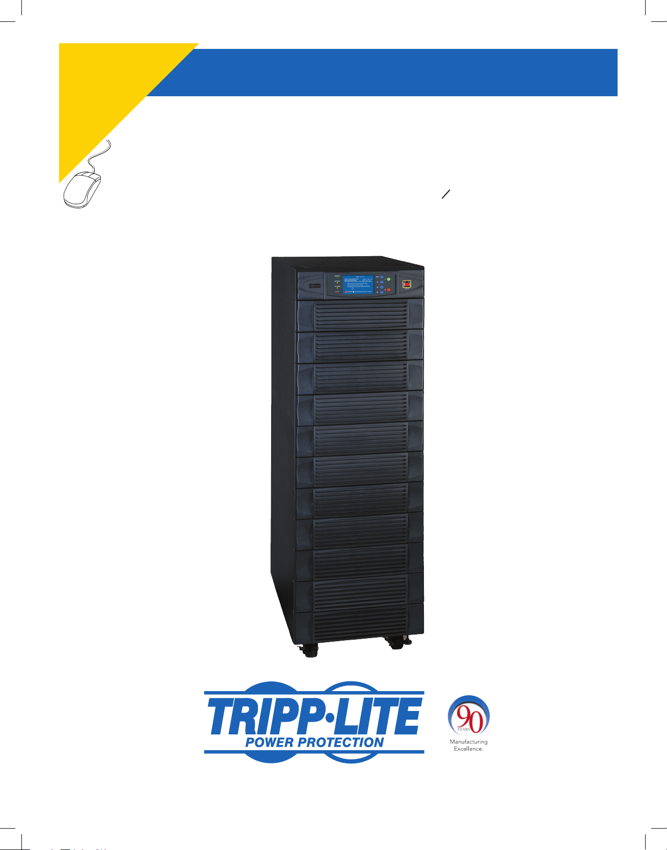
SmartOnline™ 3-Phase UPS Systems
Input/Output: 220/380V, 230/400V or 240/415V AC, 3O, 4-wire + ground
Owner’s Manual
Model: SU120KX2
Not suitable for mobile applications.
1
2
3
4
5
6
7
8
9
10
11
12
13
1111 W. 35th Street, Chicago, IL 60609 USA • www.tripplite.com/support
Copyright © 2012 Tripp Lite. All trademarks are the sole property of their respective owners.
1
12-212-93-3141.indb 1 12/28/2012 11:16:51 AM
14
Page 2
Table of Contents
1
1 Introduction 3
2 Important Safety Instructions 4
2
3 Control Panel Features 6
4 Front and Rear Panel Features 7
5 Cabinet Installation 9
3
5-1 Preparation 9
5-2 Unpacking 9
5-3 Placement 10
6 Wiring 11
4
6-1 Wiring Warnings 11
6-2 Wiring Preparation 11
6-3 UPS System Terminal Block Diagram 12
6-4 External Battery Cabinet Wiring Diagrams 12
5
6-5 Electrical and Cable Data 13
6-6 External Battery Cabinet Wiring 14
6-7 AC Input/Output Wiring (Single UPS—SUS) 14
6-8 AC Input/Output Wiring (Parallel Configuration—2x MUS) 15
6
6-9 AC Input/Output Wiring (Parallel Configuration—4x MUS) 16
7 Operating Modes 17
7-1 Online (Normal) Mode (Single UPS—SUS) 17
7
7-2 Battery Backup Mode (Single UPS—SUS) 17
7-3 Auto Bypass Mode (Single UPS—SUS) 17
7-4 Manual Bypass Mode (Single UPS—SUS) 17
7-5 On-line (Normal) Mode (Parallel UPS—MUS) 18
8
7-6 Battery Backup Mode (Parallel UPS—MUS) 18
7-7 Auto Bypass Mode (Parallel UPS—MUS) 18
7-8 Manual Bypass Mode (Parallel UPS—MUS) 19
7-9 External Maintenance Bypass (Parallel UPS—MUS) 19
9
8 Start-Up, Shutdown and Bypass 20
8-1 Control Panel and Breaker Diagrams 20
8-2 Preliminary Checklist (Single UPS—SUS) 20
8-3 Standard Start-Up Procedure (Single UPS—SUS) 21
10
8-4 Battery Start-Up Procedure (Single UPS—SUS) 22
8-5 Manual Bypass Procedure (Single UPS—SUS) 22
8-6 Shutdown Procedure (Single UPS—SUS) 24
8-7 Preliminary Checklist (Parallel UPS—MUS) 24
11
8-8 Start-Up Procedure (Parallel UPS—MUS) 25
8-9 Shutdown Procedure (Parallel UPS—MUS) 26
8-10 Switching to Manual Bypass Mode from Normal Mode
(Parallel UPS—MUS) 27
12
8-11 Switching to Normal Mode from Manual Bypass Mode
(Parallel UPS—MUS) 28
9 Power Module Status and Replacement 29
9-1 Power Module Features and Status 29
9-2 Preliminary Replacement Checklist 29
9-3 Replacement Procedure 29
10 Display and Configuration 30
10-1 Control Panel Diagram 30
10-2 Display Hierarchy 30
10-3 Default Display 31
10-3-1 Status Display 31
10-4 Main Menu 34
10-5 UPS Setup 36
10-5-1 Bypass Setup 37
10-5-2 Output Setup 38
10-5-3 Battery Setup 40
10-5-4 Charger Setup 43
10-5-5 Parallel Setup 44
10-5-6 Control & Test Setup 45
10-5-7 Local Setup 47
10-6 Maintenance 50
11 Communications 52
11-1 Communications Interfaces 52
11-2 SNMPWEBCARD Slot 52
11-3 Input Dry Contact Interface 52
11-4 Remote Emergency Power Off (EPO) Circuit Diagram 53
11-5 Auxiliary Dry Contact Input Circuit Diagram 53
11-6 External Battery Cabinet Temperature Inputs 53
11-7 External Battery Status Input 53
11-8 Output Dry Contact Interface Detail 54
11-9 Output Dry Contact Circuit Diagram 55
11-10 RS-232 Serial Port Circuit Diagram 55
11-11 Parallel Configuration Port 55
12 Specifications 56
12-1 UPS System Technical Specifications 56
12-2 UPS System Floor Loading Table 56
13 Storage and Service 57
14 Warranty 58
Español 59
Français 117
Русский 175
13
14
2
12-212-93-3141.indb 2 12/28/2012 11:16:51 AM
Page 3
1 – Introduction
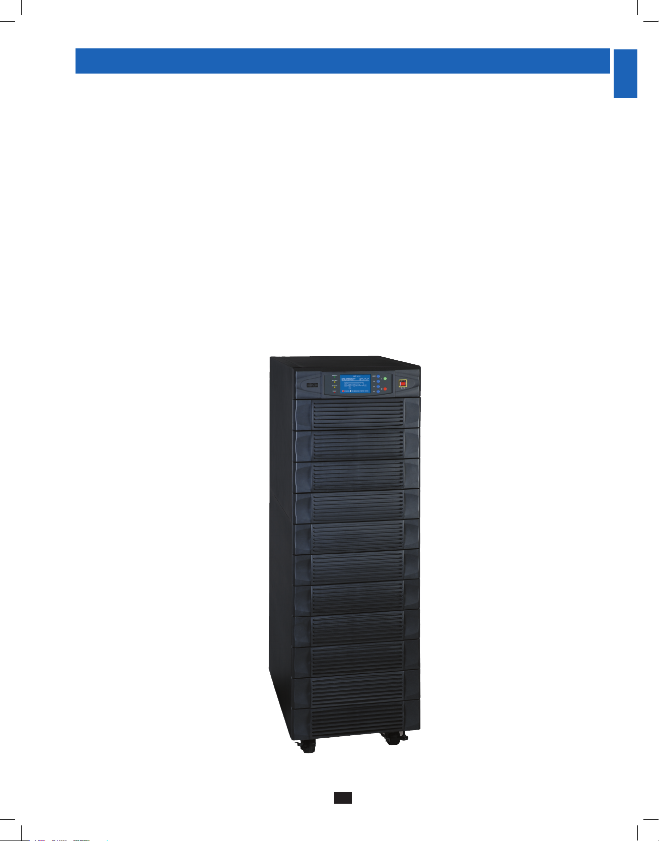
Tripp Lite’s SmartOnline 3-Phase KX2-Series UPS System (Model SU120KX2) is ideal for backing up and protecting data centers,
telecommunications (VoIP), networks, industrial facilities, security/emergency systems and more.
1
Advanced Features:
• True on-line double conversion with superior IGBT inverter technology
• Low input current THDi allows 1:1 generator sizing for maximum efficiency and cost savings
• Internal N+1 power module redundancy
• Built-in parallel or hot standby redundancy capability for increased capacity or fault-tolerance
• Up to 120kVA capacity in compact footprint; up to 480kVA in parallel capacity configuration with 4 units
• High input power factor and high efficiency with low thermal loss and low noise
• Simplified, easy-to-repair, long-life, high-availability system design
• Redundant auxiliary power and control circuits within each power module and at the system level
• Single feed input design
• Supports external battery cabinets for extended battery backup runtime
• High-resolution LCD status screen simplifies operation and delivers detailed operational information, including system block diagrams
2
3
4
5
6
7
8
9
10
11
12
13
14
3
12-212-93-3141.indb 3 12/28/2012 11:16:51 AM
Page 4

2 – Important Safety Instructions
1
SAVE THESE INSTRUCTIONS
All sections of this manual contains instructions and warnings that should be followed during the installation and operation of the UPS
2
systems described in this manual. Read all instructions thoroughly before attempting to move, install or operate the UPS systems described in
this manual. Failure to comply may invalidate the warranty and cause property damage and/or personal injury.
Location Warnings
3
• Install the UPS system in a controlled indoor environment, away from moisture, temperature extremes, flammable liquids and gasses, conductive
contaminants, dust and direct sunlight.
• Install the UPS system in a level, structurally sound location.
4
• The UPS system is extremely heavy; be extremely careful when moving or lifting the unit.
• Operate the UPS system at indoor temperatures between 32° F and 104° F (0° C and 40° C) only. For best results, maintain indoor temperatures
between 62° F and 84° F (17° C and 29° C).
• Leave adequate space around all sides of the UPS system for proper ventilation. Do not block, cover or insert objects into the external ventilation
5
openings of the cabinet.
• Do not place any object on the unit, especially containers of liquid.
• Do not mount the unit with its front or rear panel facing down (at any angle). Mounting in this manner will seriously inhibit the unit’s internal
cooling, eventually causing product damage not covered under warranty.
6
• Do not install the UPS system near magnetic storage media, as this may result in data corruption. Keep all recorded magnetic media a minimum
of 60 cm (24 inches) away from the UPS system.
• Do not attempt to stack the UPS system. Attempting to stack the UPS system may cause permanent damage and create a potential for serious
personal injury.
7
• The casters are designed for minor position adjustments within the final installation area only. The casters are not designed for moving the UPS
system over longer distances.
• The casters are not designed to provide long-term support for the UPS system after final installation. Use the levelers to provide long-term
support.
8
• When moving the UPS system, push from the front or rear, not from the sides.
• Do not attempt to unpack or move the UPS system without assistance.
Connection Warnings
9
• The power supply for the UPS system must be 3-phase rated in accordance with the equipment nameplate. It also must be suitably
grounded and wired according to all applicable national and local electrical wiring standards, codes and regulations.
• The UPS system contains hazardous high voltages that have the potential to cause personal injury or death from electric shock.
• The UPS system has its own energy source (battery – internal and/or external). The output terminals may be live even when the UPS system is
10
11
12
not connected to an AC supply.
• If the UPS system receives power from a motor-powered AC generator, the generator must provide clean, filtered, computer-grade output.
• Use of this equipment in life support applications where failure of this equipment can reasonably be expected to cause the failure of the life
support equipment or to significantly affect its safety or effectiveness is not recommended. Do not use this equipment in the presence of a
flammable anesthetic mixture with air, oxygen or nitrous oxide.
• The UPS system is designed to power modern computer loads and associated peripheral devices. Do not use the UPS system to power pure
inductive or capacitive loads.
• Input and output wiring should be performed by trained, qualified electricians only.
• Due to high leakage current, a proper earth ground connection is essential before connecting the AC supply.
• Isolate the UPS system before working on the circuit. An easily accessible disconnect device should be incorporated in the fixed wiring. The
disconnect device must disconnect all line conductors simultaneously when opened.
13
14
4
12-212-93-3141.indb 4 12/28/2012 11:16:52 AM
Page 5

2 – Important Safety Instructions (continued)
Battery Warnings
• The UPS system does not require routine maintenance. There are no user-serviceable parts inside. Only qualified service personnel should open
the access panels for any reason.
• Batteries present a risk of electrical shock and burns from high short-circuit current. Battery connection or replacement should be performed
only by qualified service personnel, observing proper precautions. Turn off the UPS system before connecting or disconnecting internal
batteries. Use tools with insulated handles. Do not open the batteries. Do not short or bridge the battery terminals with any object.
• Replace batteries with equivalent batteries available from Tripp Lite. Do not operate the UPS system without batteries.
• The batteries are recyclable. Refer to local codes for disposal requirements.
• Do not dispose of the batteries in a fire, mutilate the batteries or open the battery coverings.
• Battery fuses should be replaced by qualified service personnel only. Blown fuses must be replaced with the same number and type of fuses.
• Potentially lethal voltages exist within the UPS system as long as the battery supply is connected. Service and repair should be performed
by trained personnel only, while the UPS system is turned off or placed into bypass mode. Disconnect internal batteries (if present) before
performing any service work by switching off the internal battery circuit breaker and removing the battery fuse(s). Disconnect external batteries
(if present) by switching off the external battery cabinet breaker and disconnecting the external battery cabling from the UPS system.
• Do not connect or disconnect batteries when the UPS system is operating from the battery supply or when the unit is not in bypass mode.
• External batteries must be replaced by equivalent batteries available from Tripp Lite.
• Before connecting an external battery cabinet to the UPS system, read the external battery cabinet’s documentation. Use only external battery
cabinets that have been approved by Tripp Lite.
• If the UPS system remains off for an extended period of time, it should be turned on periodically to allow the batteries to recharge. The UPS
system should be turned on and the batteries should be recharged at least one uninterrupted 24-hour period every 3 months. Failure to recharge
the batteries periodically may cause irreversible battery damage.
1
2
3
4
5
6
Wiring Warnings
• See Section 6-1 for wiring warnings
7
8
9
10
11
12
13
14
5
12-212-93-3141.indb 5 12/28/2012 11:16:52 AM
Page 6
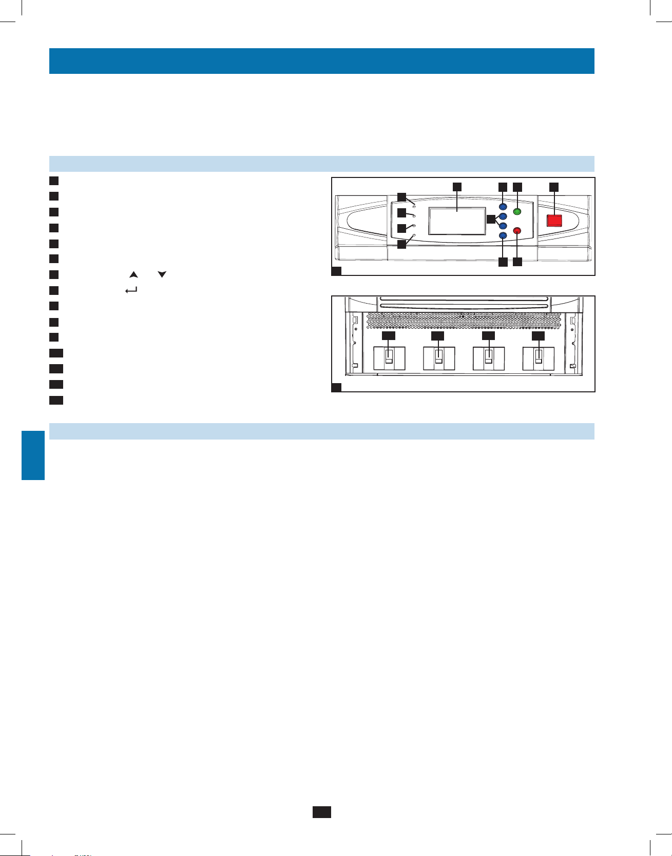
3 – Control Panel Features
1
A E F G H I J KBCD
2
3
4
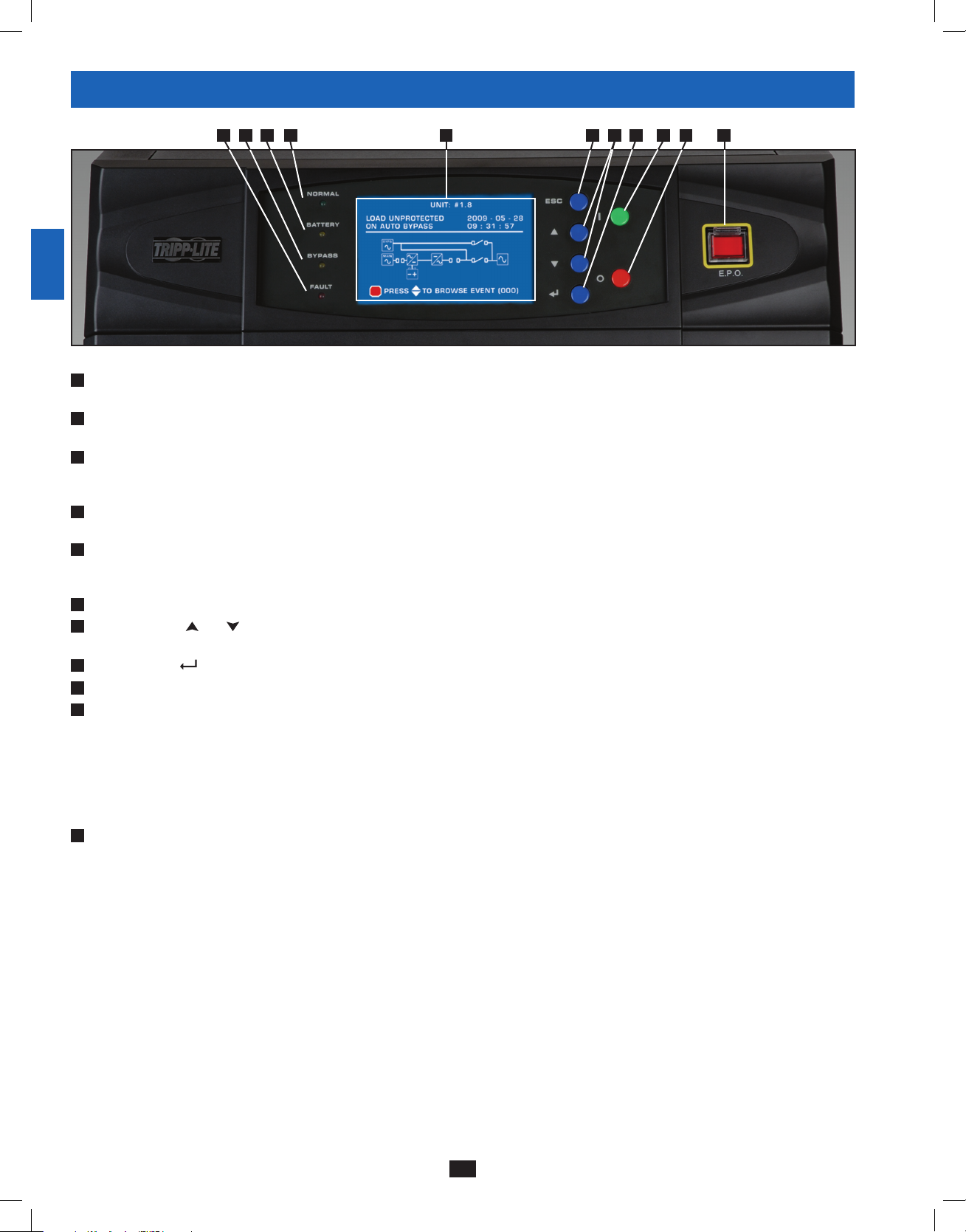
• “NORMAL” LED: This green light illuminates to indicate that the UPS system is in online (normal) mode. The primary AC input supply is
A
present and within standard operating parameters.
• “BATTERY” LED: This amber light illuminates when the UPS system is in battery backup mode, discharging the batteries to provide power
B
5
6
7
8
9
10
11
12
13
to connected equipment. An audible alarm will also sound.
• “BYPASS” LED: This amber light illuminates when the UPS system is in bypass mode (auto bypass or manual bypass). Battery backup
C
power will not be available to connected equipment while the UPS system is in bypass mode, but connected equipment loads will be
supported by the bypass (reserve) power source.
• “FAULT” LED: This red light illuminates when any UPS system or input power fault occurs. Available diagnostic information will be
D
displayed on the LCD screen.
• LCD Status Screen: This illuminated LCD status screen displays text and graphics to indicate a wide range of UPS system operating
E
conditions and diagnostic data. Note: The LCD backlight will turn off after 10 minutes of inactivity. Turn on the backlight by momentarily
pressing the ON button or one of the scroll buttons.
• “ESC” (Escape) Button: Press this button to return to the previous page or menu.
F
G
• Scroll Buttons ( and ): Press these buttons to move the cursor up or down and navigate the control panel menus and screens. These
buttons are also used for data entry in several screens.
• Enter Button ( ): Press this button to select a menu item or confirm a setting change.
H
• ON Button: Press and hold this button for 3 seconds to turn the UPS system’s inverter ON.
I
J
• OFF Button: Press and hold this button for 3 seconds to turn the UPS system’s inverter OFF. If the UPS system is in online (normal) mode, it
will switch to auto bypass mode.
Note: Switching the inverter OFF does not stop the converter stage of the UPS and therefore, the connected battery is still charging as
required.
Note: After switching the inverter OFF, if the battery circuit breaker or AC main input circuit breaker are opened and remain open for an
extended period of time, the batteries should be recharged periodically. At a minimum, the batteries should be charged for an uninterrupted
24-hour period every 3 months to maintain their longest usable life. Failure to recharge the batteries may cause irreversible battery damage.
• “EPO” (Emergency Power Off) Button: Press this button to turn the UPS system’s output OFF and also disable bypass output.
K
If the UPS system is in battery backup mode when the EPO button is activated:
• Main output and bypass output are turned off, the alarm sounds, fans shut down after approximately one minute, and control circuitry
remains active.
• Releasing the EPO button (by pressing it again) turns off the UPS system completely, including the alarm and control circuit. Press the
ON button for 3 seconds to restart the UPS system.
If the UPS system is in online (normal) mode when the EPO button is activated:
• Main output and bypass output are turned off, the alarm sounds, fans and control circuitry remain active.
• Releasing the EPO button (by pressing it again) turns off the alarm and places the UPS system in auto bypass mode. Press the ON button
for 3 seconds to return the UPS system to online (normal) mode.
See Section 10 – Display and Configuration for detailed information about the control panel’s menus and displays.
14
6
12-212-93-3141.indb 6 12/28/2012 11:16:53 AM
Page 7
4 – Front and Rear Panel Features
A
B
1
2
3
4
5
6
D E
C
G
H H
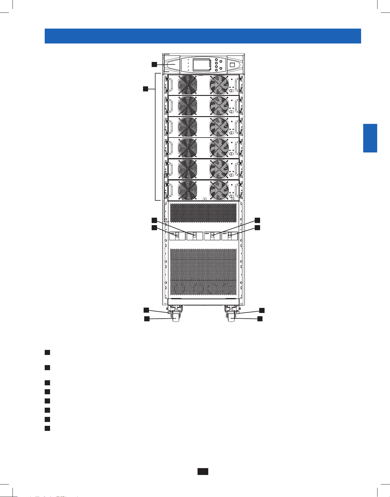
Front View
• Control Panel: The control panel allows the operator to monitor and control the UPS system. See Section 3 – Control Panel Features for
A
more information.
B
• Internal Power Modules: 20kVA internal power modules can be replaced in the field without powering down connected equipment loads.
The SU120KX2 contains 6 internal power modules capable of N+1 redundancy.
C
• Output Circuit Breaker Switch (Q4): Controls AC output power.
D
• Manual Bypass Circuit Breaker Switch (Q3): Controls AC input power to the UPS system during manual bypass operation.
E
• Bypass Input Circuit Breaker Switch (Q2): Controls AC input power to the UPS system during auto bypass operation.
F
• Main Input Circuit Breaker Switch (Q1): Controls AC input power to the UPS system during online (normal) operation.
G
• Levelers: The levelers provide long-term support for the UPS system.
H
• Casters: The casters are designed for small position adjustments within the final installation location only; they are not designed for moving
the UPS system over longer distances. The casters are not designed to provide long-term support for the UPS system after final installation.
Use the levelers to provide long-term support.
F
G
7
8
9
10
11
12
13
14
7
12-212-93-3141.indb 7 12/28/2012 11:16:56 AM
Page 8
4 – Front and Rear Panel Features (continued)
1
J
2
L
M
K
N
3
4
5
6
7
O
8
H
9
H
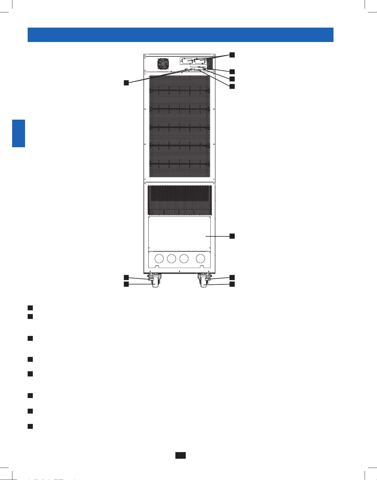
• Levelers: The levelers provide long-term support for the UPS system.
I
• Casters: The casters are designed for small position adjustments within the final installation location only; they are not designed for moving
10
11
12
13
14
the UPS system over longer distances. The casters are not designed to provide long-term support for the UPS system after final installation.
Use the levelers to provide long-term support.
• Accessory Slot: Remove the cover panel to install a Tripp Lite SNMPWEBCARD accessory. The SNMPWEBCARD accessory provides an
J
Ethernet interface for the UPS system and enables remote monitoring and control via SNMP, Web browser or telnet. Visit www.tripplite.com
for more information about the SNMPWEBCARD accessory.
K
• RS-232 Serial Communications Port: This DB9 port connects the UPS system to compatible workstations or servers, enabling automatic
shutdown during extended blackouts and monitoring of operating and power conditions.
L
• Parallel Configuration Port: These DB9 ports connect the UPS system to another UPS system, or chain of systems, of identical type and
capacity for use in a parallel configuration (up to 4 systems).*
*A pair of DIP switches are set to 1/On or 0/Off on each UPS, depending on the parallel configuration.
M
• Input Dry Contact Interface: This interface receives dry contact signals that allow the UPS system to receive commands and monitor
external battery conditions. See Section 11 - Communications for more information.
• Output Dry Contact Interface: This interface allows the UPS system to send information via dry contact communications. See Section 11 –
N
Communications for more information.
• Terminal Block Cover: Remove the terminal block cover to access the UPS system’s input, bypass input, external battery cabinet, output and
O
grounding connection terminals. Wiring conduits pass through the circular knockouts in the terminal block cover. See Section 6 – Wiring for
more information, including a detailed diagram of the terminal block.
I I
Rear View
H
8
12-212-93-3141.indb 8 12/28/2012 11:17:05 AM
Page 9
5 – Cabinet Installation
1
Read Section 2 – Important Safety Instructions Before Installation
5-1 Preparation
The UPS system must be installed in a structurally sound area with a level floor that is able to bear the weight of the UPS system, any external
battery cabinet and other equipment that will be installed nearby. The installation site should also have a dedicated AC circuit available that is
compatible with the UPS system’s input requirements. (See Section 12 – Specifications for details on input requirements and floor loading
requirements.) Before unpacking the unit, you should transport the shipping container closer to the final installation site to minimize the distance
you will need to move the unit after the protective shipping container has been removed. If you plan to store the UPS system for an extended
period before installation, follow the instructions in Section 13 – Storage and Service. (Unpacking and storage instructions are also printed on the
“Unpacking and Storage Instructions” sheet secured to the shipping container.) Warning: Do not attempt to unpack or move the UPS system
without assistance.
5-2 Unpacking
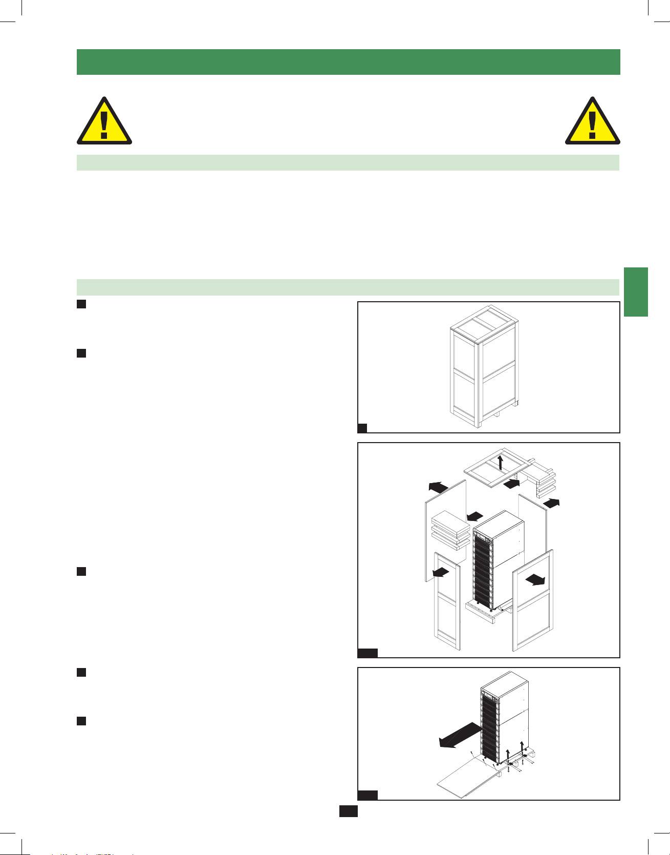
1
• Inspect the shipping container(s) for visible damage. If you
determine that the unit has been damaged during shipping, contact
Tripp Lite for assistance. Do not attempt to use the UPS system if
it has been damaged or mishandled.
2
• Confirm that the shipping container is upright and use a
screwdriver to remove its top panel, front panel and back panel.
Also remove the plastic wrap and interior cushioning material.
Confirm that the model name and rating at the rear of the cabinet
match the unit you ordered. Examine the cabinet for any damaged
or loosened parts. Confirm that the shipping container includes the
accessories that ship with the unit.
The UPS system should include:
• AnRS-232serialcable
• Aparallelconfigurationcable
• AremoteEPOwiringconnector(2contacts)
• Adryinputcontactconnector(4contacts)
• Adryoutputcontactconnector(12contacts)
• SoftwareCD-ROM
If any of the package contents are missing or damaged, please
contact Tripp Lite for assistance.
3
• Confirm that the unit is stable, then remove the side panels from
the shipping container.
1
2
3
4
5
6
7
8
9
10
11
2-3
• Remove the bolts from the shipping brackets securing the unit
4
to the pallet, then remove the shipping brackets from the UPS
system. Warning: Be extremely careful, as the unit could shift
unexpectedly.
5
• Use several of the screws you removed in step 2 to attach the top
panel of the shipping container to the front edge of the shipping
pallet. The smooth surface of the panel should face upward so
that it can be used as a ramp for rolling the unit off the shipping
pallet. Do not attempt to use the top panel as a ramp if it is cracked
or otherwise structurally damaged. Make sure the casters at the
bottom of the unit are unlocked. Using extreme caution, slowly roll
the unit down the ramp with the aid of several assistants.
12-212-93-3141.indb 9 12/28/2012 11:17:18 AM
4-5
9
12
13
14
Page 10
5 – Cabinet Installation (continued)
1
5-3 Placement
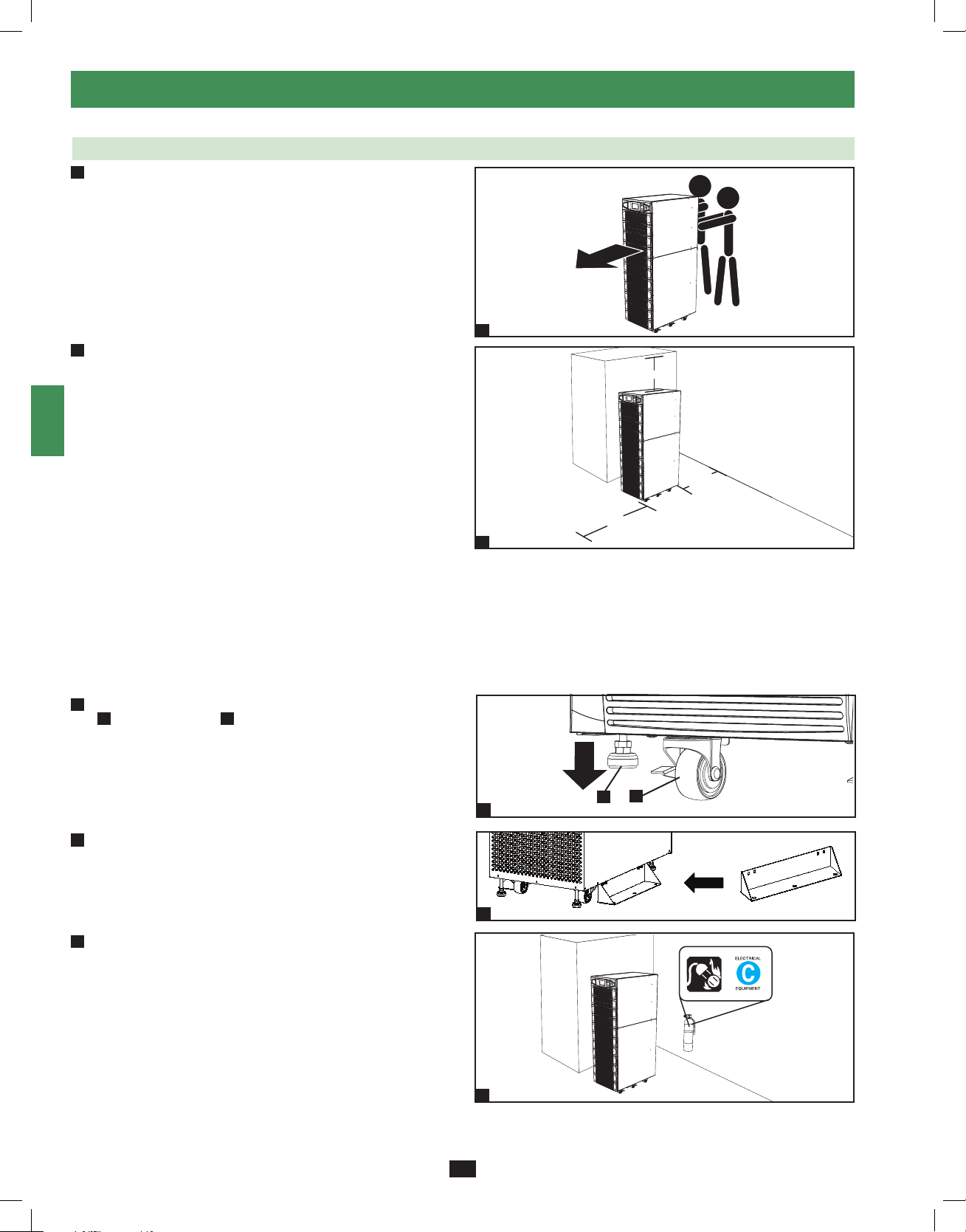
• Use the casters to move the UPS system for a short distance over
1
2
3
4
5
6
7
8
9
a level, smooth, stable surface. Do not attempt to use the casters
to move the UPS system over longer distances. The UPS system
should be moved close to its final installation location inside
its shipping container before it is unpacked from the shipping
container. Use a mechanical device of sufficient capacity to move
the shipping container. Warning: The UPS system could tip if it
is moved over an unstable surface. Be extremely careful when
moving the UPS system. Push the UPS system from the front or
rear, not from the sides.
2
• Position the UPS system in a structurally sound area with a
level floor that is able to bear the weight of the UPS system,
any external battery cabinets and other equipment that will be
installed nearby. The installation site should also have a dedicated
AC circuit available that is compatible with the UPS system’s
input requirements. (See the Section 12 – Specifications for
more information about input requirements and floor loading
requirements.) The UPS system must be installed in a clean,
secure environment with a relative humidity less than 90% (noncondensing). Operate the UPS system at indoor temperatures
between 17° C and 29° C (62° F and 84° F). Prevent damage to
cabling by using suitable protective conduits. In order to maintain
proper airflow and service access, you must maintain the following
clearances:
• At least 100 cm (39.4”) clearance in front of the UPS system.
• At least 50 cm (19.7”) clearance behind the UPS system.
• At least 50 cm (19.7”) clearance above the UPS system.
Warning: The cooling fans circulate air from front to back. Do not
use any air conditioning or fan that blows air directly toward the
rear of the UPS system.
• After moving the UPS system to its final location, lock the casters
3
A
and use the levelers B to stabilize the cabinet. Ensure that all
four levelers make firm contact with the floor.
1
50 cm (19.7 in.)
50 cm (19.7 in.)
100 cm (39.4 in.)
2
A
B
10
• Attach the balance supports on either side of UPS using 4 bolts.
4
Caution: The UPS system may topple over in unexpected
circumstances if both balance supports are not properly installed.
3
11
4
• For emergency use, install a fire extinguisher rated for energized
5
12
electrical equipment fires (Class C rating or exact equivalent, with
a non-conductive extinguishing agent) near the UPS system.
13
5
14
10
12-212-93-3141.indb 10 12/28/2012 11:17:21 AM
Page 11
6 – Wiring
DANGER! LETHAL HIGH VOLTAGE HAZARD!
All wiring should be performed by a qualified electrician in accordance with the warnings in this manual, all applicable
electrical and safety codes, and good wiring practices. Incorrect wiring may damage the UPS system severely and cause
serious personal injury and property damage. Read Section 2 – Important Safety Instructions before proceeding.
1
2
6-1 Wiring Warnings
• De-energize all input and output power sources of the UPS system before installing cables or making electrical connections.
• Use flexible cable of sufficient length to permit UPS system servicing. The maximum cable length is 10 m (32.8 ft).
• Use ferrule caps to cover termination cables within mechanical lugs, or use compression lugs in order to prevent frayed ends from shorting on
the UPS system terminal block.
• Use cabling rated VW-1, FT-1 or better.
• Use cable sleeves and connector clamps.
• The neutral conductor must be the same size as the current conductors.
• Tighten all field wiring terminal connections with a torque of at least 3.95 N·m (35 in·lb); a torque of 11.8 N·m (100 in·lb) is required for the
“In”, “Out” and “Battery” bolt-screw terminals.
• Confirm that all cables are marked correctly according to their purpose, polarity, phase and diameter.
• If the UPS system’s input/output power source is wye-wye, then “Neutral” and “Ground” must not be re-bonded at the UPS.
• If the input power source has VNG>0, install a grounded wye secondary isolation transformer with a properly bonded neutral to ground before
the UPS system and input power source.
• For equipment requiring a neutral connection to an IT power distribution system that requires neutral isolation upon disconnect, the disconnect
device must be a four-pole device and must disconnect all line conductors and the neutral conductor. If a disconnect device interrupts the neutral
conductor, it must simultaneously interrupt all line conductors.
• Allow the batteries to charge uninterrupted for 24 hours after the initial wiring connection and UPS startup.
• Observe proper polarity by connecting negative to negative, positive to positive and the center point of the battery string to the normal “N”
terminal. Do not bond the battery’s “N” terminal to the AC power “Neutral” or “Ground” as damage may result. Failure to observe proper
polarity will damage the UPS system and create a serious risk of personal injury and property damage.
• Observe proper phase by connecting R to R, S to S, T to T and N to N. Source power phase rotation must be verified as RST before powering
the UPS. Failure to observe proper phase will damage the UPS system and create a risk of personal injury and property damage.
3
4
5
6
7
8
6-2 Wiring Preparation
• De-energize all input and output (AC and DC) of the UPS system and external battery cabinet (if present).
• Mark all cables according to their correct purpose, polarity, phase and diameter.
• Review the diagrams in Section 6-3 and Section 6-4 to familiarize yourself with the terminal blocks.
• Consult the table in Section 6-5 to find the correct electrical input/output characteristics for the UPS system.
Note: If the UPS system’s input/output power source is wye-wye, then “Neutral” and “Ground” must not be re-bonded at the UPS. If the input
power source has VNG>0, install an isolation transformer as part of the UPS input power source and bond “Neutral” and “Ground” together at
the isolation transformer’s output.
9
10
11
12
13
14
11
12-212-93-3141.indb 11 12/28/2012 11:17:22 AM
Page 12
6 – Wiring (continued)
1
6-3 UPS System Terminal Block Diagram
2
3
4
R RS ST TN NN
AC Input Battery Output
5
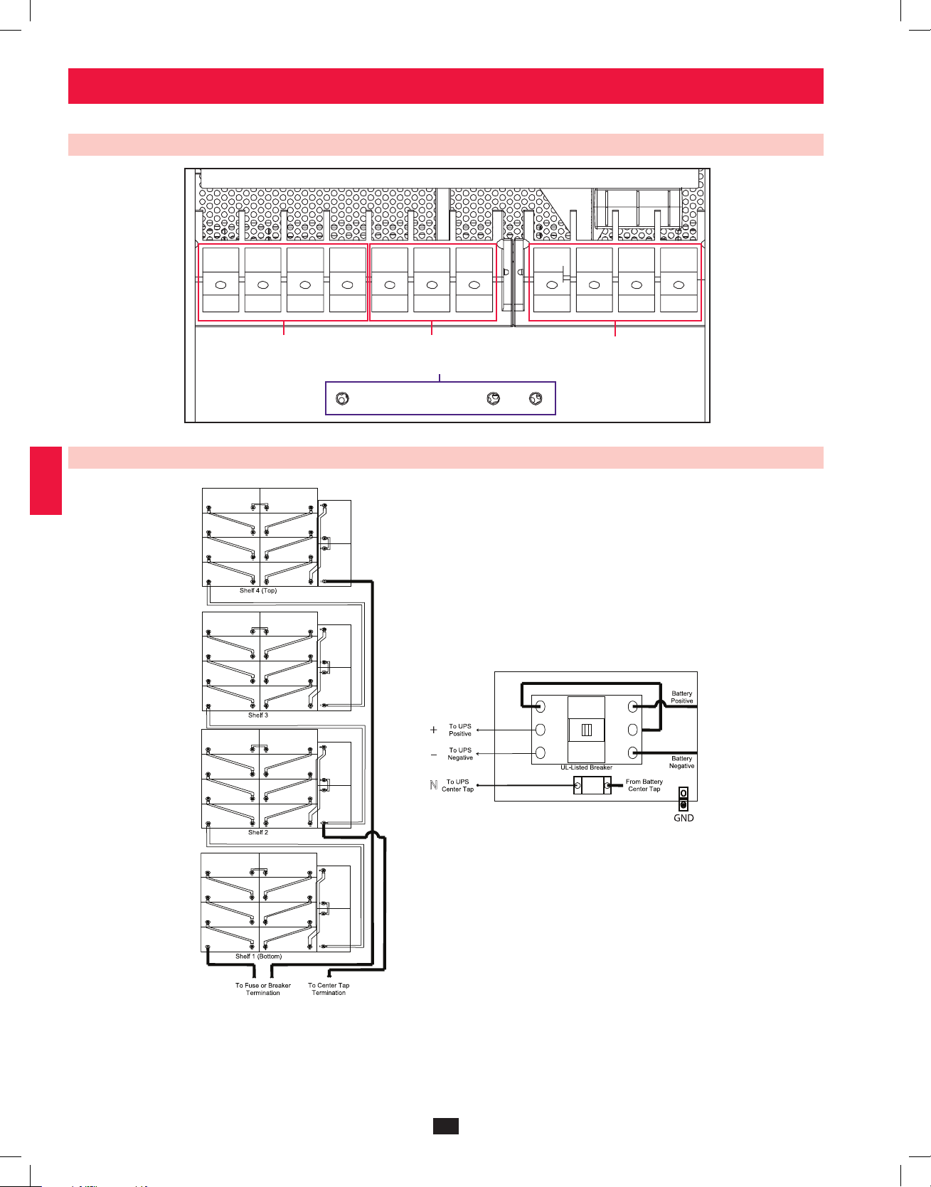
6-4 External Battery Cabinet Wiring Diagrams
6
7
8
+
Grounding Terminals
–
9
10
11
12
13
Battery and Circuit Breaker Diagram shown for illustration only; consult the battery cabinet’s documentation for exact specifications.
Notes:
• All internal wiring is UL-listed, MTW, 125C Hi-Flex cable.
• Terminal block is UL-recognized and rated for 600 VDC.
• Breaker is UL-listed and rated for 250 A, 600 VDC, 25 KAIC.
14
• Cabinets with breakers are shipped with the breaker in the off/open position.
• Battery arrangements shown are typical but may vary depending on cabinet and battery type.
12
12-212-93-3141.indb 12 12/28/2012 11:17:22 AM
Page 13
6 – Wiring (continued)
6-4 External Battery Cabinet Wiring Diagrams (continued)
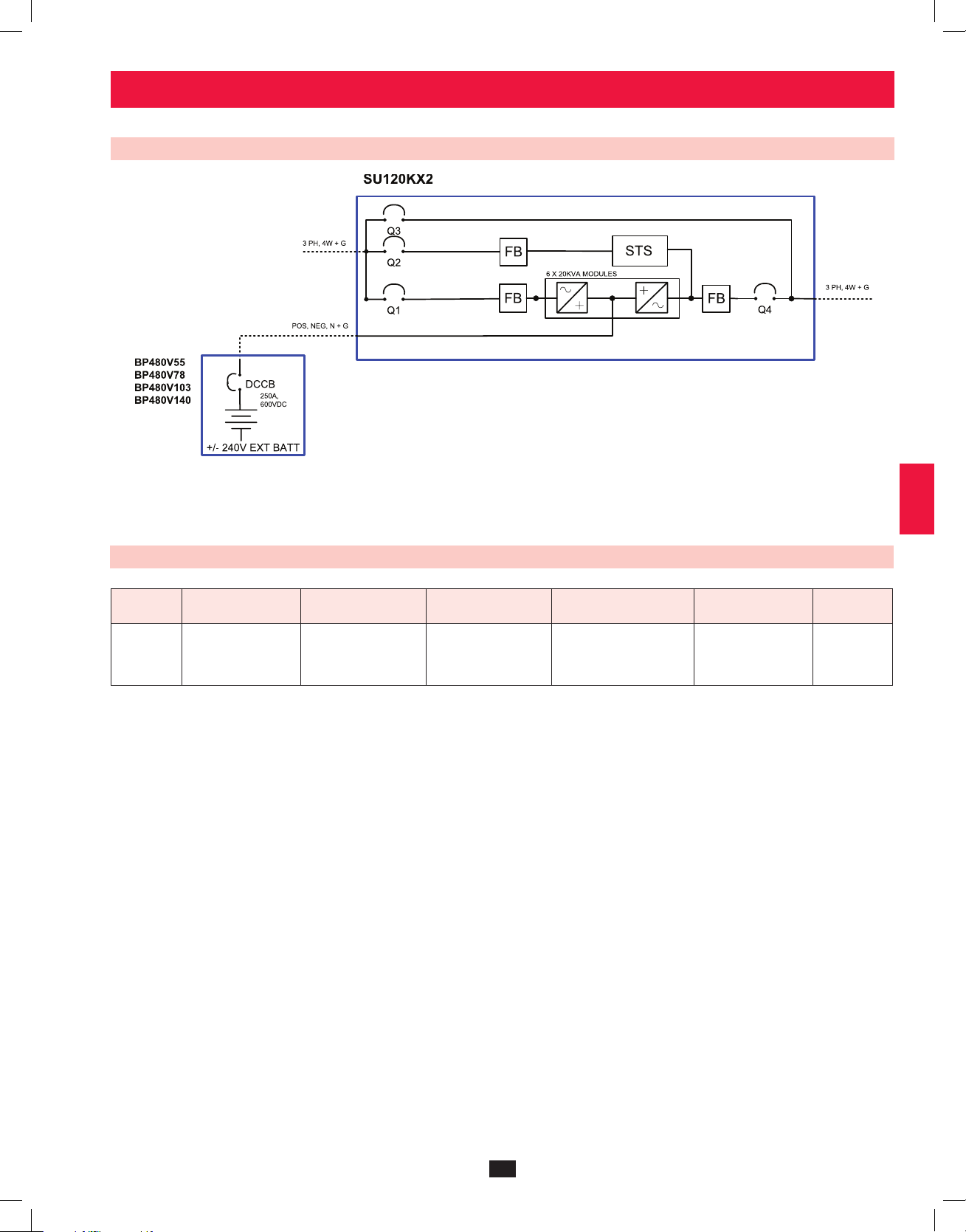
SU120KX2 schematic representation shown
External Battery Cabinets
10 Year Cabinet: 55AH, 78AH, 103AH, 140AH; 250A, 600VDC Circuit Breaker
1
2
3
4
5
6
6-5 Electrical and Cable Data
Model Input Output
SU120KX2
380Y/220V,
400Y/230V, or
415Y/240V AC, 3Ø,
4-wire + ground
380Y/220V,
400Y/230V, or
415Y/240V AC, 3Ø,
4-wire + ground
Input, Bypass and
Output Breaker Size
225A
Input, Reserve, Output
and Battery Cable Size
120mm²
(4/0 AWG)
Battery Circuit
Breaker Fuse Size
250A
Battery
Cable Size
120mm²
(4/0 AWG)
7
8
9
10
11
12
13
14
13
12-212-93-3141.indb 13 12/28/2012 11:17:23 AM
Page 14
6 – Wiring (continued)
1
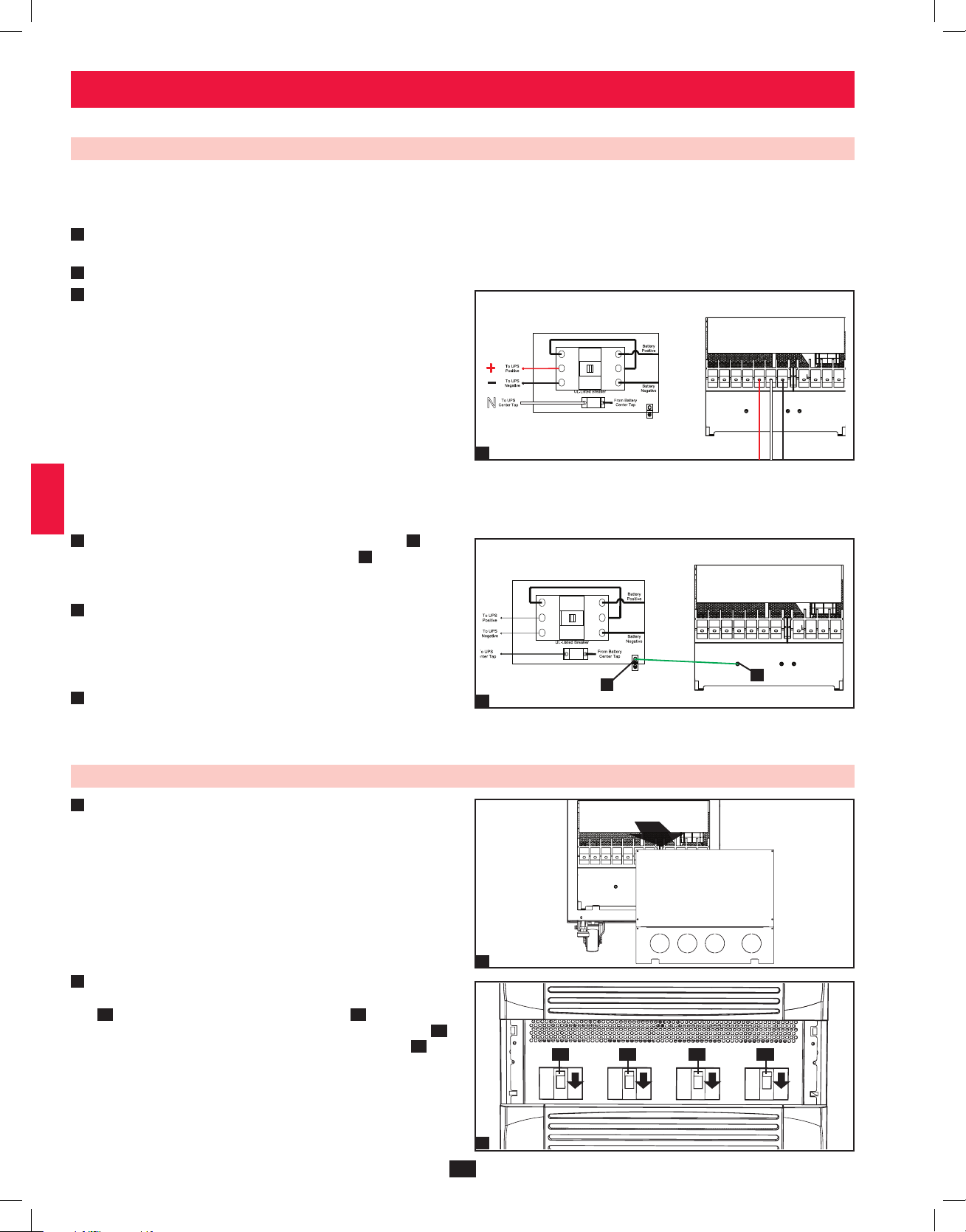
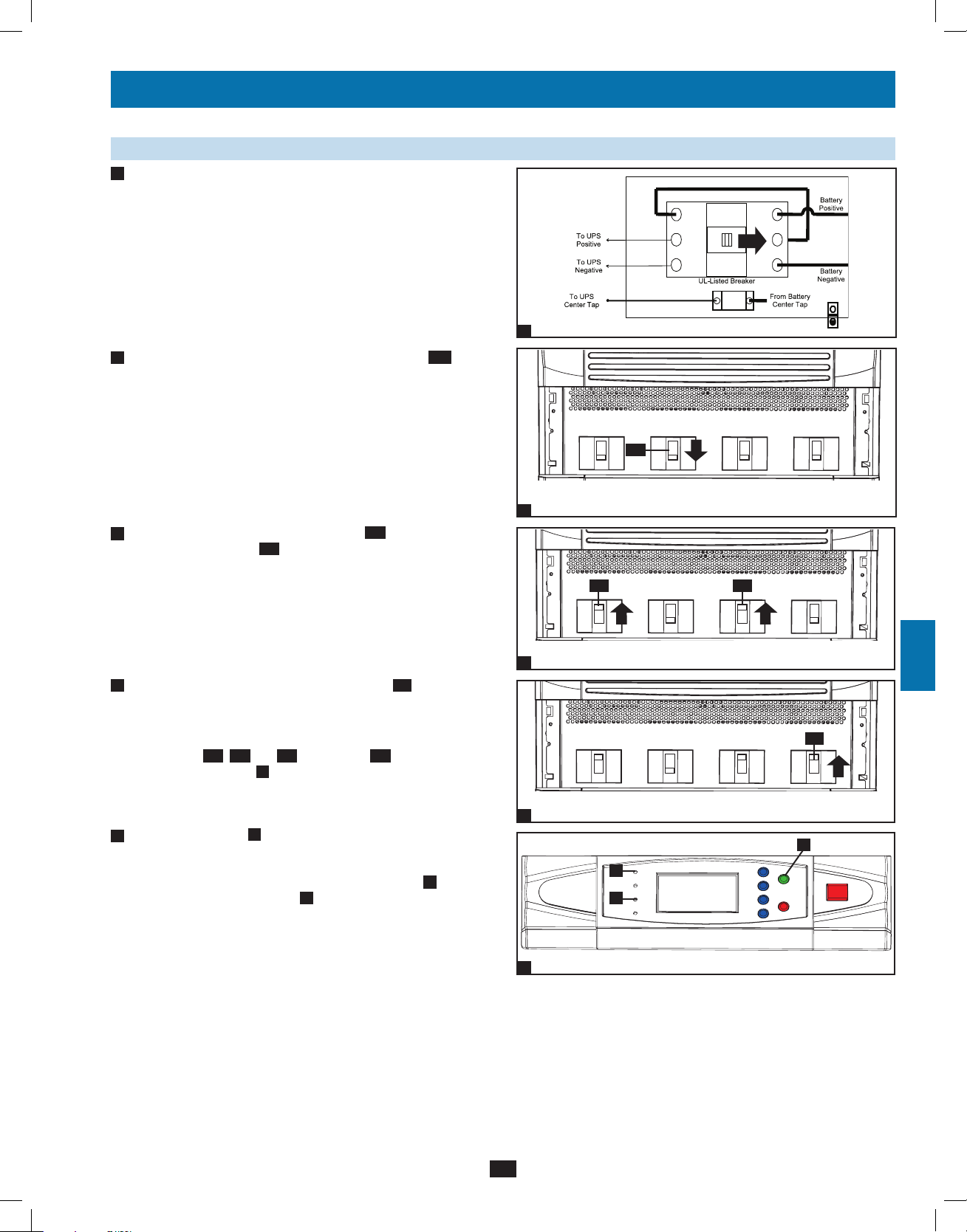
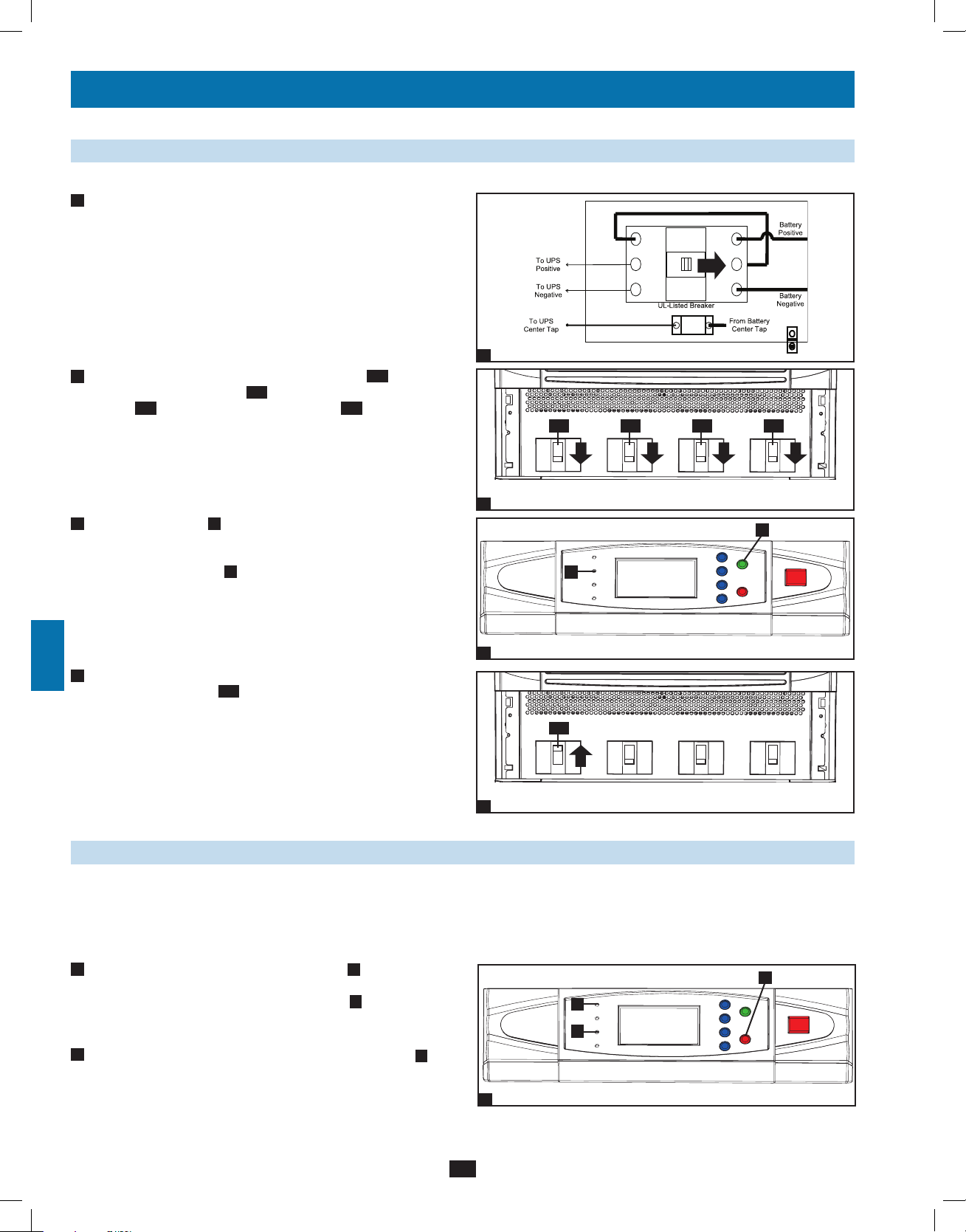
6-6 External Battery Cabinet Wiring
Warning: External battery cabinets vary. Read the external battery cabinet’s documentation before attempting to connect it to the UPS
2
system. Use only external battery cabinets that have been approved by Tripp Lite.
Note: An external battery cabinet is required with model SU120KX2. Contact Tripp Lite for external battery cabinet ordering information.
• De-energize all input and output (AC and DC) of the UPS system and external battery cabinet, and confirm that the external battery cabinet
1
breaker switch is off. (If the UPS system has already been wired to an AC power source, see Section 8-6 for shutdown instructions.)
3
• Remove the terminal block covers from the UPS. Remove the front cover and conduit plates (if provided) of the external battery cabinet.
2
3
• Connect the positive (+), normal (N) and negative (-) UPS
system connection terminals of the external battery cabinet to the
corresponding positive (+), normal (N) and negative (-) external
4
5
6
7
8
9
battery connection terminals of the UPS system. See Section 6-3
and the external battery cabinet’s documentation for terminal
block diagrams. See Section 6-4 for wiring diagrams. See Section
6-5 for cable size requirements. Cabling should be protected by
flexible conduit and routed through the appropriate knockouts in
the terminal block cover. Warning: Observe proper polarity by
connecting negative to negative, positive to positive and center
point of the battery string to normal “N”. Failure to observe
proper polarity will damage the UPS system and create a risk
of personal injury and property damage.
Note: Do not bond the battery “N” terminal to the AC power
neutral or ground as damage may result.
4
• Connect the external battery cabinet’s grounding terminal
UPS system’s corresponding grounding terminal
(25 mm²) ground cable. Keep the ground cable connected at all
times after installation.
5
• Connect the UPS system’s primary grounding terminal to
your facility’s earth ground with a 4 AWG (25 mm²) minimum
equipment grounding conductor (EGC) cable within the same
conduit used in item 3 above. Keep the EGC cable connected at all
times after installation.
• Replace the conduit landing cover of the external battery cabinet. If
6
you do not plan to wire the AC input/output of the UPS system at
this time, replace the terminal block cover of the UPS system.
with a 4 AWG
B
A
to the
3
A
4
B
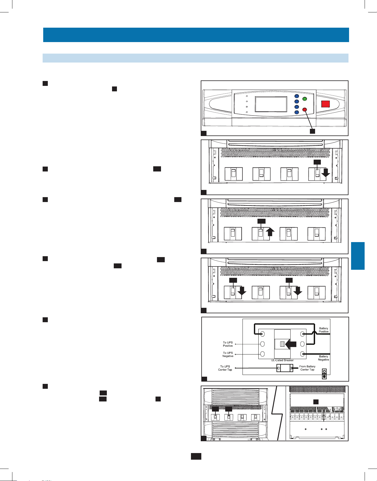
6-7 AC Input/Output Wiring (Single UPS—SUS)
1
• After de-energizing all input and output (AC and DC) of the UPS
10
system, remove the terminal block cover from the UPS system.
11
12
2
• Remove the UPS system’s front bezel to expose the circuit
breakers. First, confirm that the main input circuit breaker switch
13
Q1
and the bypass input circuit breaker switch
Second, confirm that the manual bypass circuit breaker switch
is off. Third, confirm that the output circuit breaker switch
off.
Q2
are both off.
14
Q4
1
Q3
is
2
14
Q4 Q2 Q1Q3
12-212-93-3141.indb 14 12/28/2012 11:17:25 AM
Page 15
6 – Wiring (continued)
6-7 AC Input/Output Wiring (Single UPS—SUS) (continued)
3
• Connect the UPS system’s primary grounding terminal
to your facility’s earth ground with a 4 AWG (25 mm²)
minimum equipment grounding conductor cable. Keep
the EGC cable connected at all times after installation.
4
• Confirm the phase of each cable, then connect the cables
according to the UPS system terminal block diagram in
Section 6-3. See Section 6-5 for cable size requirements.
Cabling should be protected by flexible conduit and
routed through the appropriate knockouts in the terminal
block cover. Warning: Observe proper phase rotation
by connecting R to R, S to S, T to T and N to N.
Failure to observe proper phase rotation will damage
the UPS system and create a risk of personal injury
and property damage.
5
• Replace the UPS system’s terminal block cover.
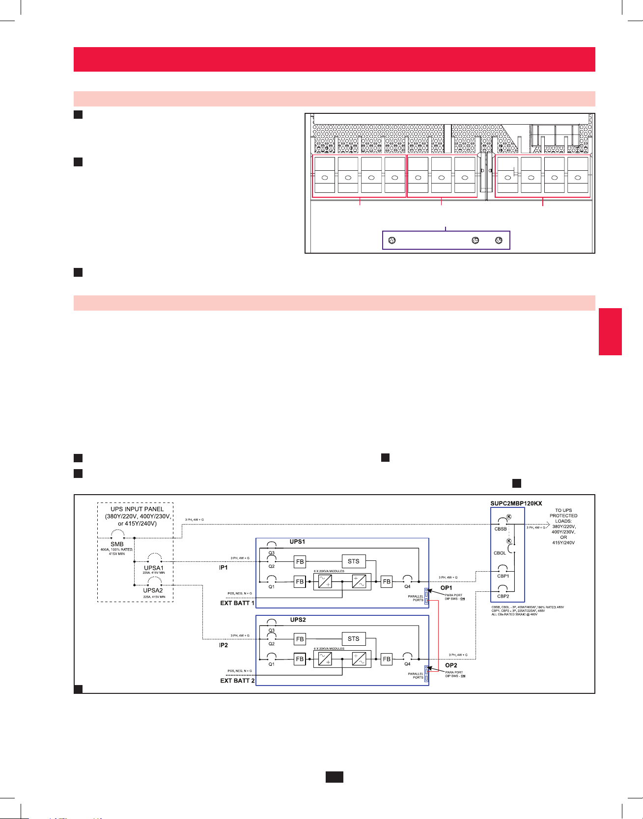
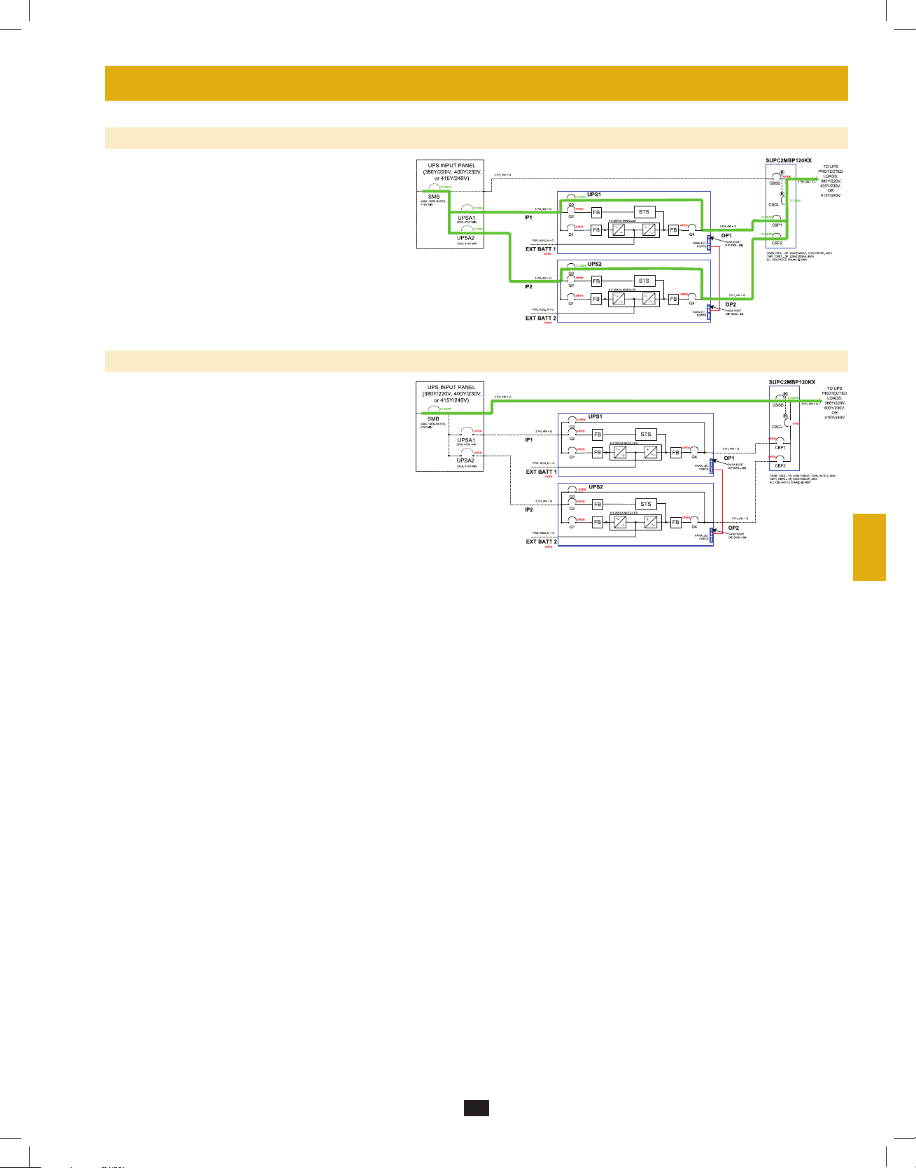
6-8 AC Input/Output Wiring: Parallel Configuration – 2x MUS (Multiple Unit System)
Parallel Configuration – MUS Warnings:
• The total cable length for each UPS must be within 10% of each of the other parallel-configured UPS in order to prevent
unbalanced load sharing between the individual UPS. (IP1 + OP1 = IP2 + OP2 = IP3 + OP3 = IP4 + OP4, minimum/maximum
deviation must be < 10%).
• Parallel configurations are supported for 2, 3, or 4 UPS units only. Do not attempt to configure more than 4 UPS systems via
parallel configuration.
• Each UPS system to be parallel configured for either N+1 redundancy or capacity, must have the same rating, kVA capacity, and
system and power module level firmware version (see Section 10-6). Attempting to configure dissimilar UPS systems may be
inhibited or may cause damage to the UPS systems and create a risk of personal injury and property damage.
• Each UPS must have its parallel group set to 2 and a different “Parallel ID” that indicates the UPS systems are operating in
parallel (see Section 10-5-5 for more details).
• Follow the steps in Section 6-7, wiring the UPS systems as shown in the diagram
1
• Each UPS is shipped with (1) parallel configuration cable included. Connect each UPS parallel communication port(s) as shown and select
2
the correct position of the parallel port dip switches (either both ON (down) or both OFF (up) as shown in the diagram
R RS ST TN NN+–
AC Input Battery Output
Grounding Terminals
1
.
1
.
1
2
3
4
5
6
7
8
9
10
11
12
DASHED LINES INDICATE USER-SUPPLIED
PARTS AND CABLES.
1
13
14
15
12-212-93-3141.indb 15 12/28/2012 11:17:25 AM
Page 16
6 – Wiring (continued)
1
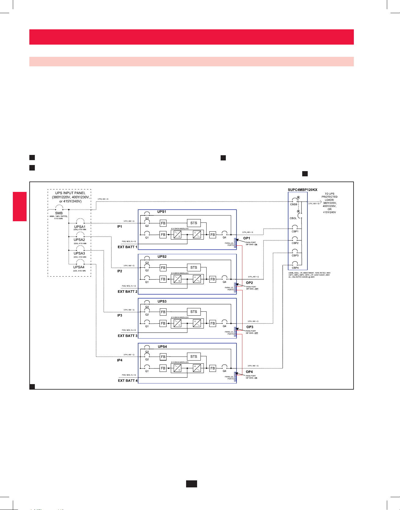
6-9 AC Input/Output Wiring: Parallel Configuration – 4x MUS (Multiple Unit System)
Parallel Configuration – MUS Warnings:
2
3
4
5
6
• The total cable length for each UPS must be within 10% of each of the other parallel-configured UPS in order to prevent
unbalanced load sharing between the individual UPS. (IP1 + OP1 = IP2 + OP2 = IP3 + OP3 = IP4 + OP4, minimum/maximum
deviation must be < 10%).
• Parallel configurations are supported for 2, 3, or 4 UPS units only. Do not attempt to configure more than 4 UPS systems via
parallel configuration.
• Each UPS system to be parallel configured for either N+1 redundancy or capacity, must have the same rating, kVA capacity, and
system and power module level firmware version (see Section 10-6). Attempting to configure dissimilar UPS systems may be
inhibited or may cause damage to the UPS systems and create a risk of personal injury and property damage.
• Each UPS must have its parallel group set to 2 and a different “Parallel ID” that indicates the UPS systems are operating in
parallel (see Section 10-5-5 for more details).
1
• Follow the steps in Section 6-7, wiring the UPS systems as shown in the diagram
• Each UPS is shipped with (1) parallel configuration cable included. Connect each UPS parallel communication port(s) as shown and select
2
the correct position of the parallel port dip switches (either both ON (down) or both OFF (up) as shown in the diagram
1
.
1
.
10
11
12
7
8
9
DASHED LINES INDICATE USER-SUPPLIED
PARTS AND CABLES.
1
13
14
16
12-212-93-3141.indb 16 12/28/2012 11:17:26 AM
Page 17
7 – Operating Modes
This section provides a basic description of the UPS system’s operating modes. The one-line diagrams used are schematic representations. For
more information about switching between operating modes, refer to Section 8 – Start-Up, Shutdown and Bypass.
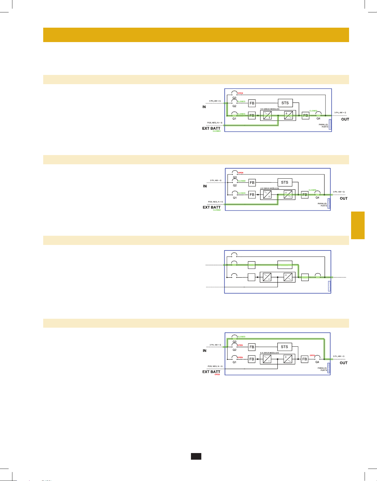
7-1 Online (Normal) Mode (Single UPS—SUS)
In online (normal) mode, the UPS system’s rectifier converts incoming
AC utility power to DC power that charges the batteries and supplies the
inverter. The inverter transforms the DC power to precision-regulated,
pure sine wave AC power that supports the operation of connected
equipment. This dual conversion technology isolates connected
equipment from all power problems and ensures that connected
equipment receives ideal power at all times.
1
2
3
4
7-2 Battery Backup Mode (Single UPS—SUS)
When a power outage or other extreme power event occurs, the UPS
system automatically switches from normal mode to battery backup
mode. The UPS system’s batteries (internal and/or external) provide
emergency DC power to the inverter. The inverter transforms the DC
power to precision-regulated, pure sine wave AC power that supports
the operation of connected equipment.
7-3 Auto Bypass Mode (Single UPS—SUS)
If the inverter malfunctions due to excessive temperature, overload,
output short circuit, abnormal voltage or battery problems, the inverter
will shut down. If the UPS system detects a bypass (reserve) power
source that conforms to normal parameters, then the UPS system
automatically switches to auto bypass mode to continue supplying
power to connected equipment. When all problems are eliminated, the
UPS system switches back to online (normal) mode automatically.
7-4 Manual Bypass Mode (Single UPS—SUS)
If UPS system maintenance or repair is required, you can bypass
the UPS system and enable bypass (reserve) power manually. After
confirming that the bypass source is present (input AC available and Q3
open), transfer to manual bypass mode by first pressing the off button to
stop the inverter. This transfers the UPS to static internal bypass. Next,
switch the UPS system into manual bypass mode. (See Section 8-5 for
complete manual bypass procedure.) The one-line diagram illustrates
the system status and flow of power after the manual bypass procedure
has been completed. This allows service technicians to perform
maintenance or repair procedures without interrupting the flow of AC
power to connected equipment. Warning: After switching to manual
bypass mode to perform selected maintenance or repair procedures,
the UPS may require complete shutdown to affect those repairs. Use
of an external 3-breaker maintenance bypass panel can facilitate
this and still maintain AC power to the connected equipment.
3 PH, 4W + G
IN
POS, NEG, N + G
EXT BATT
CLOSED
5
6
7
OPEN
Q3
CLOSED
FB
Q2
CLOSED
Q1
6 X 20KVA MODULES
FB
STS
FB
CLOSED
Q4
PARALLEL
3 PH, 4W + G
PORTS
8
OUT
9
10
11
12
13
14
17
12-212-93-3141.indb 17 12/28/2012 11:17:27 AM
Page 18
7 – Operating Modes (continued)
1
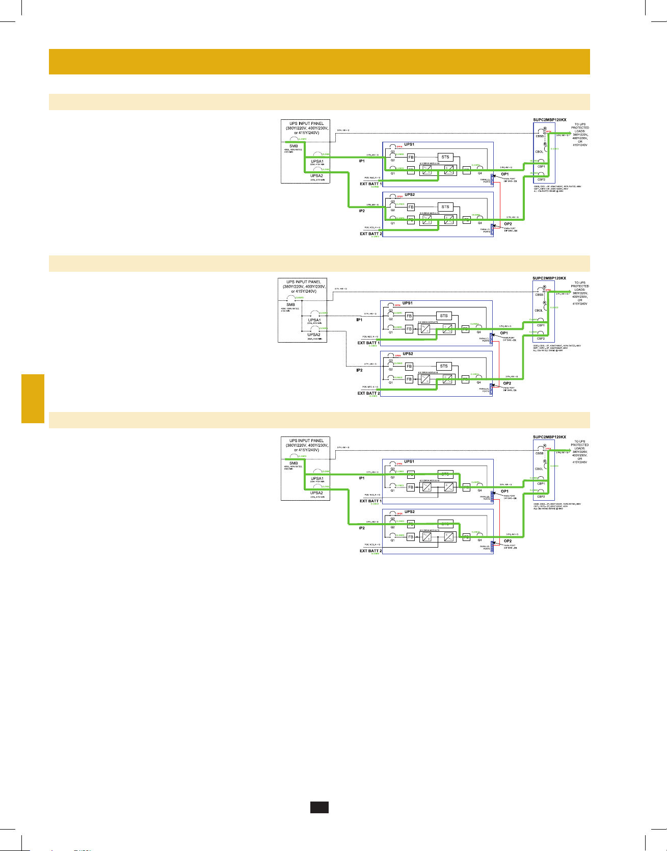
7-5 Online (Normal) Mode (Parallel UPS—MUS)
Parallel configuration provides UPS system redundancy or
increased total capacity. Under parallel configuration, the
2
total load is shared by 2 to 4 UPS systems. If one of the UPS
systems malfunctions, the total connected equipment load
is supported by the remaining UPS systems. If the total load
exceeds the capacity of the remaining UPS systems, the MUS
3
will switch all UPS units to auto bypass mode.
The diagram illustrates the on-line mode for a 2x MUS.
4
7-6 Battery Backup Mode (Parallel UPS—MUS)
Similar to battery backup mode for a single UPS system
(Section 7-2), except the total connected equipment load is
5
shared by the parallel UPS systems (2 to 4).
The diagram illustrates the battery backup mode for a
2x MUS.
6
7
7-7 Auto Bypass Mode (Parallel UPS—MUS)
Similar to auto bypass mode for a single UPS system
(Section 7-3), except with parallel UPS systems (2 to 4).
8
The diagram illustrates the auto bypass mode for a 2x MUS.
9
10
11
12
13
14
18
12-212-93-3141.indb 18 12/28/2012 11:17:28 AM
Page 19
7 – Operating Modes (continued)
7-8 Manual Bypass Mode (Parallel UPS—MUS)
Similar to manual bypass mode for a single UPS system
(Section 7-4), except with parallel UPS systems (2 to 4).
Note: All UPS systems must be switched into manual bypass
mode.
The diagram illustrates the manual bypass mode for a
2x MUS.
7-9 External Maintenance Bypass Mode (Parallel UPS—MUS)
Utilizing the external parallel cabinet with system level
maintenance bypass panel, the parallel UPS systems can be
completely isolated for maintenance or repair procedures
while the connected equipment remains powered.
Transfer to external maintenance bypass mode should only
be accomplished once each individual UPS unit has been
placed in auto or manual bypass first.
1
2
3
4
5
6
7
8
9
10
11
12
13
14
19
12-212-93-3141.indb 19 12/28/2012 11:17:29 AM
Page 20
8 – Start-Up, Shutdown and Bypass
1
Warning: The UPS system’s output voltage and frequency are set at 220/380V, 50Hz by default. If you require output voltage of 230/400V
or 240/415V, or a frequency of 60Hz, you must change the UPS system’s output voltage and/or frequency by accessing the output setup
menu described in Section 10-5-2. You must place the UPS system in bypass mode before changing the output voltage. Do not connect your
2
equipment to the UPS system’s output until you have set the proper parameters.
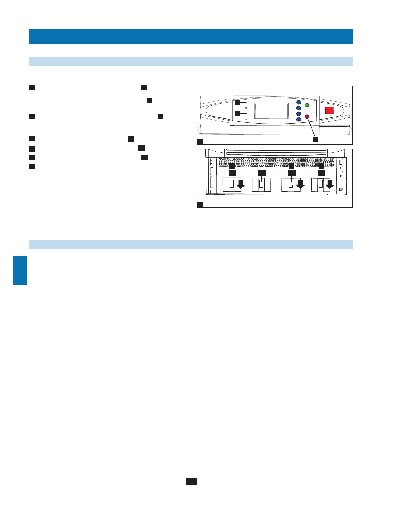
8-1 Control Panel and Breaker Diagrams
• “NORMAL” LED
A
3
• “BATTERY” LED
B
• “BYPASS” LED
C
• “FAULT” LED
D
4
• LCD Status Screen
E
F
• “ESC” (Escape) Button
• Scroll Buttons ( and )
G
• Enter Button ( )
H
5
• ON Button
I
• OFF Button
J
K
• “EPO” (Emergency Power Off) Button
6
• Main Input Circuit Breaker Switch
Q1
• Bypass Input Circuit Breaker Switch
Q2
• Manual Bypass Circuit Breaker Switch
Q3
• Output Circuit Breaker Switch
Q4
7
A
B
C
D
1
Q4
Output Manual
2
Circuit Breaker Switches (UPS System Front Panel)
E
Control Panel
Q3
Bypass
G
Q2
Bypass
Input
F
I
J
H
Q1
Main
Input
K
8-2 Preliminary Checklist (Single UPS—SUS)
• All circuit breaker switches should be off, including the breaker of the external battery cabinet.
8
• Confirm that no voltage potential exists between Neutral and Ground.
• Confirm that the input power source matches the rating (voltage, frequency and phase) of the UPS system.
Note: After start-up, the UPS system will perform a brief self-test and display the results on the LCD screen. After a successful self-test, the UPS
system will provide AC power to the connected equipment load.
9
10
11
12
13
14
20
12-212-93-3141.indb 20 12/28/2012 11:17:30 AM
Page 21
8 – Start-Up, Shutdown and Bypass (continued)
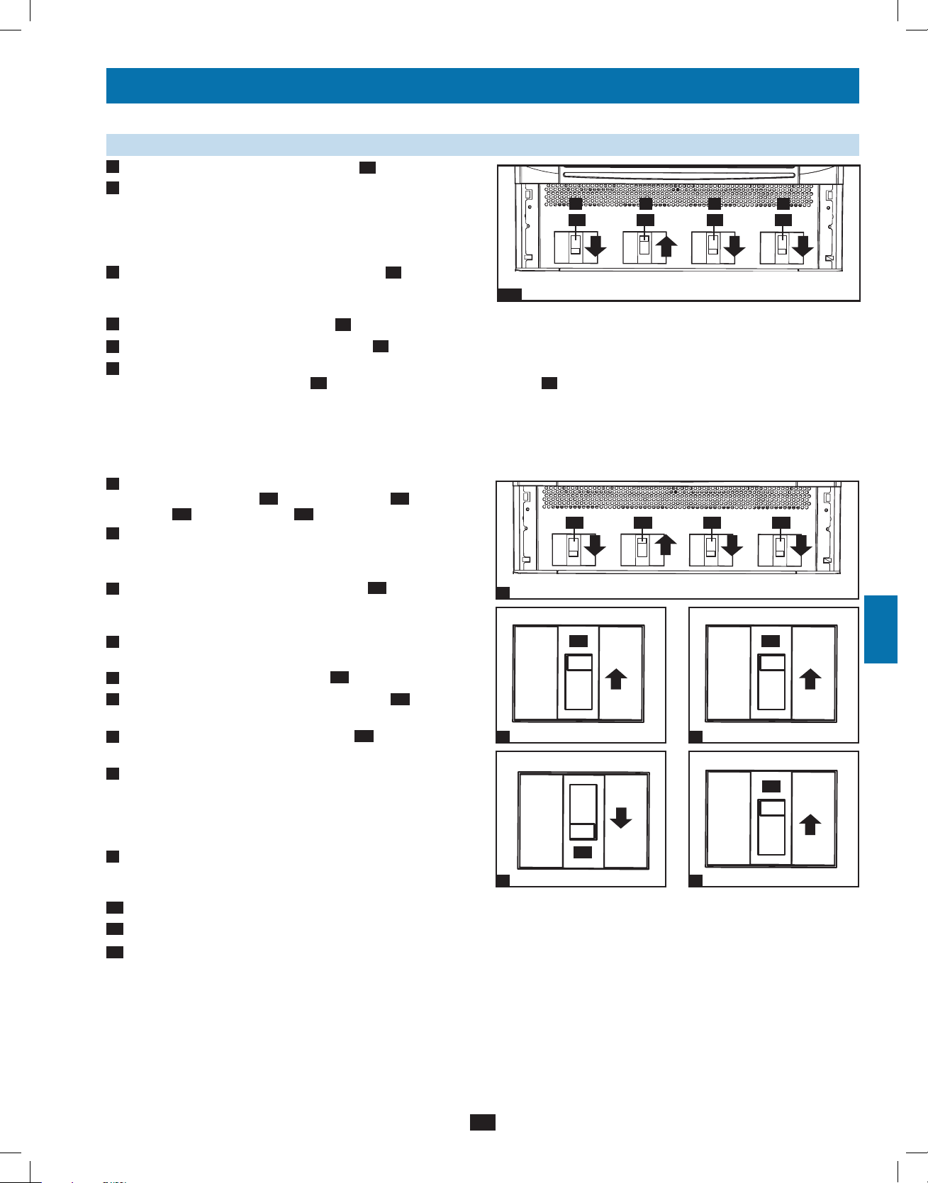
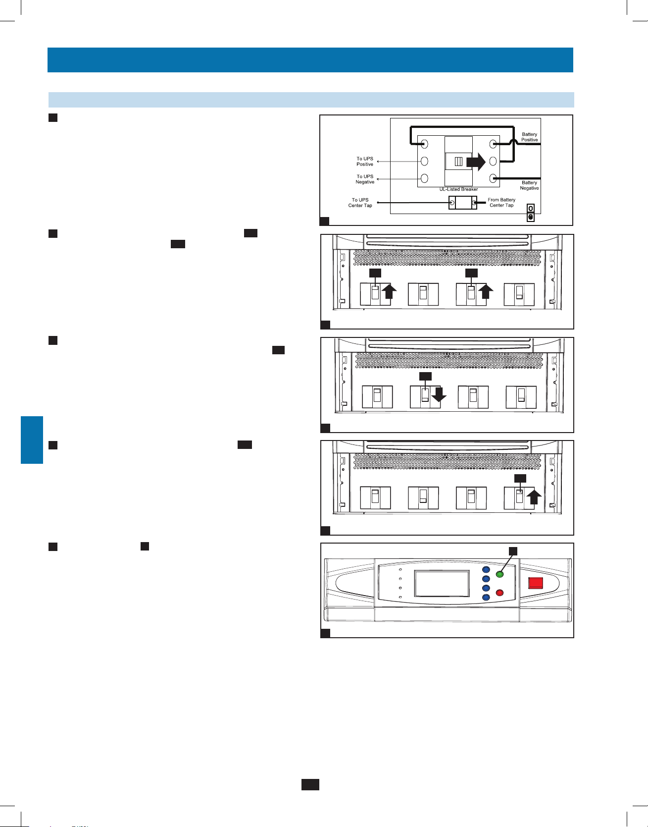
8-3 Standard Start-Up Procedure (Single UPS—SUS)
• With the external battery cabinet connected, switch on the circuit
1
breaker of the external battery cabinet.
1
2
3
2
• Confirm that the manual bypass circuit breaker switch Q3 is off.
• Switch on the bypass input breaker switch Q2 and then output
3
circuit breaker switch Q4. After a brief initialization process, the
LCD screen will show “ON AUTO BYPASS”, the “BYPASS”
LED will illuminate and UPS system output will be supplied by
the input power source via the bypass path.
4
• Switch on the main input circuit breaker switch Q1. If the AC
input power source is normal, the UPS system is ready for start-up.
Note: In addition to the external battery cabinet breaker being
turned on, the normal on-line running status of the four (4) circuit
breakers is: Q1, Q2 and Q4 On (closed); Q3 Off (open). This is
shown in the diagram 4 to the right.
1
4
5
Q3
Output Manual
2
Q4 Q2
Output Manual
3
Bypass
Bypass
Bypass
Input
Bypass
Input
Main
Input
Main
Input
Q1
6
7
8
9
• Press the ON button A for 3 seconds (until you hear a beep), then
5
release the button. The inverter will activate and synchronize with
the bypass source, then automatically switch from auto bypass
mode to online (normal) mode. The “BYPASS” LED B will turn
off and the “NORMAL” LED C will illuminate.
Output Manual
4
C
B
5
Bypass
Bypass
Input
A
Main
Input
10
11
12
13
14
21
12-212-93-3141.indb 21 12/28/2012 11:17:31 AM
Page 22
8 – Start-Up, Shutdown and Bypass (continued)
1
8-4 Battery Start-Up Procedure (Single UPS—SUS)
Note: The battery must be at least partially charged for this operation to succeed.
2
• With the external battery cabinet connected, switch on the circuit
1
breaker of the external battery cabinet.
3
4
2
• Confirm that the main input circuit breaker switch Q1, bypass
input circuit breaker switch Q2, manual bypass circuit breaker
switch Q3 and output circuit breaker switch Q4 are all off.
5
6
3
• Press the ON button A for 3 seconds (until you hear a beep), then
release the button. The inverter will activate and use stored DC
battery power to supply AC power to the output circuit breaker.
7
The “BATTERY” LED
Warning: The output voltage and frequency must be set to the
desired values PRIOR to applying UPS inverter output to the
connected load (See Section 10-5-1).
B
will illuminate.
8
• After confirming output voltage and frequency are correct, turn on
4
output circuit breaker Q4 to supply battery-derived power to the
connected equipment.
9
1
Q3Q4
Output
2
B
3
Q4
Manual
Bypass
Q2 Q1
Bypass
Input
A
Main
Input
10
Output
4
Manual
Bypass
Bypass
Input
Main
Input
8-5 Manual Bypass Procedure (Single UPS—SUS)
Warning: Placing the UPS system in manual bypass will disable the inverter and power all loads from the manual bypass source path, but
11
the UPS system will still be energized. Before performing maintenance or repair on the UPS system, shut down and de-energize the UPS
system completely by following the steps in Section 8-5. Although connected equipment loads will be powered through the bypass power
path, they will not receive battery backup in the event of a utility power failure or out limits event.
To transfer the connected equipment load to Manual Bypass from NORMAL mode:
1
• With the UPS in NORMAL mode (green LED A ON, LCD
12
displays “Load Protected – On Line Mode”), stop the inverter by
pressing and holding the red OFF (“O”) button B until the UPS
beeps, then release the button and answer “YES” to the question
“Transfer to Bypass Mode?”. The UPS should transfer to Bypass.
13
2
• Confirm the UPS is in BYPASS mode (amber Bypass LED C is
ON; LCD displays “Load Unprotected – On Auto Bypass”). Do
not proceed if it is not in BYPASS mode.
A
C
1
B
14
22
12-212-93-3141.indb 22 12/28/2012 11:17:32 AM
Page 23
8 – Start-Up, Shutdown and Bypass (continued)
8-5 Manual Bypass Procedure (Single UPS—SUS) (continued)
3
• Turn OFF the MAIN INPUT circuit breaker Q1.
4
• Wait until the Power Module fans turn OFF (this may take a
minute or two), then turn OFF the BATTERY BREAKER. Note:
The external battery cabinets will have the BATTERY BREAKER
behind the front door/panel or elsewhere.
5
• Turn ON the MANUAL BYPASS circuit breaker Q3. The LCD
will display “Load Unprotected – On Manual Bypass” and you will
hear an audible alarm.
6
• Turn OFF the OUTPUT circuit breaker Q4.
7
• Turn OFF the BYPASS INPUT circuit breaker Q2. The unit’s LCD will go blank after a few seconds.
• The critical load is now supported by unconditioned utility power in manual bypass mode. In this mode, only the manual bypass path
8
3-8
(including manual bypass breaker Q3), the load terminals of the output breaker Q4] and the terminal block contain hazardous voltage,
allowing qualified service personnel to perform maintenance or repair.
Note: Use of an external 3-breaker maintenance bypass panel is recommended if the connected equipment is to be powered during complete
de-energized maintenance or repair/service procedures on the UPS system.
To transfer the critical load to NORMAL mode from Manual Bypass mode:
1
1. Confirm the UPS is in MANUAL BYPASS (the MANUAL
BYPASS circuit breaker Q3 is ON; the OUTPUT Q4, BYPASS
INPUT Q2 and MAIN INPUT Q1 circuit breakers are OFF).
2
2. Turn ON the BATTERY BREAKER. For the external battery
cabinets, the BATTERY BREAKER will be behind the front door/
panel or elsewhere.
3. Turn ON the BYPASS INPUT circuit breaker Q2 (the amber
3
Bypass LED should come on and the LCD will display “Load
1
Unprotected-On Manual Bypass).
4. Confirm the amber BYPASS LED is ON. Do not proceed if it is
4
not ON.
5. Turn ON the OUTPUT circuit breaker Q4.
5
6
6. Turn OFF the MANUAL BYPASS circuit breaker Q3. The LCD
will display “Load Unprotected-On Auto Bypass”.
7. Turn ON the MAIN INPUT circuit breaker Q1. The Power
7
3
Module fans will turn ON.
8. Press and hold the green ON button until the UPS beeps, then
8
release the button. The UPS will perform a self-test diagnostic and
the LCD will display “Self Diagnosis”. After the UPS self-test is
completed, the UPS will transfer to NORMAL mode (green LED
ON and LCD displays “Load Protected-On Line Mode”).
9. Confirm there are no active alarms present (“!” on the display and
9
audible beeping). If an alarm is present, press the UP or DOWN
arrows to display the active alarm. Correct the action as required.
10
10. Scroll through the Measure Menu and confirm all input and output power readings are within the recommended specifications.
11
11. If any problems are noted, contact your technical support personnel for further assistance.
12. The critical load is now supported by conditioned battery back-up power.
12
6
6 5 7 3
Q3 Q1Q4 Q2
Output Manual
Q4 Q3 Q2 Q1
Output Manual
Q2
Q3
Bypass
Bypass
Bypass
Input
Bypass
Input
5
7
Q4
Q1
Main
Input
Main
Input
1
2
3
4
5
6
7
8
9
10
11
12
13
14
23
12-212-93-3141.indb 23 12/28/2012 11:17:34 AM
Page 24
8 – Start-Up, Shutdown and Bypass (continued)
1
8-6 Shutdown Procedure (Single UPS—SUS)
Warning: The UPS system shutdown procedure will eliminate the AC power output for all loads. Before shutdown, confirm that all loads
2
are turned off or place the UPS system in manual bypass mode (See Section 8-5) to keep loads powered by the bypass power path.
• If the UPS is in NORMAL mode (green LED A ON, LCD
1
displays “Load Protected-On Line Mode”), then you must stop the
inverter by pressing and holding the OFF button B until the UPS
3
4
5
6
beeps, then release the button. The UPS will transfer to Bypass.
2
• Confirm the UPS is in BYPASS (amber Bypass LED C is ON;
LCD displays “Load Unprotected-On Auto Bypass”). Do not
proceed if it is not on BYPASS.
3
• Turn OFF the OUTPUT circuit breaker Q4.
• Turn OFF the MAIN INPUT circuit breaker Q1.
4
5
• Turn OFF the BYPASS UNIT circuit breaker Q2.
6
• Wait until the Power Module fans turn OFF and the LCD display
goes blank (this may take a minute or two), then turn OFF the
BATTERY BREAKER. The external battery cabinets will have the
BATTERY BREAKER behind the front door/panel or elsewhere.
Note: If the UPS system remains off for an extended period of
time, it should be turned on periodically to allow the batteries to
recharge. The UPS system should be turned on and the batteries
should be recharged at least one uninterrupted 24-hour period
every 3 months. Failure to recharge the batteries periodically may
cause irreversible battery damage.
1
2
Position of circuit breaker switches shown as in manual bypass mode.
A
C
3 5 4
Q3 Q1Q4 Q2
Output Manual
Bypass
Bypass
Input
B
Main
Input
7
8-7 Preliminary Checklist (Parallel UPS—MUS)
Warning: Parallel configurations of two, three or four UPS systems (for N+1 redundancy or capacity) are allowed. Do not attempt to link
more than four UPS systems via parallel configuration. All UPS systems must have the same rating, kVA capacity and power module
level firmware version (See Section 10-6) for parallel UPS configuration. Attempting to link dissimilar UPS systems will damage the UPS
8
systems and create a serious risk of personal injury and property damage.
• All circuit breaker switches should be off, including the battery breakers of the external battery cabinets.
• Confirm that no voltage potential exists between Neutral and Ground.
9
10
• Confirm that the input power source matches the rating (voltage, frequency and phase) of the UPS systems.
• Each UPS must have its parallel group set to 2 and a different “Parallel ID” that indicates the UPS systems are running in parallel.
See Section 10-5-5 for more details.
Note: After start-up, the UPS systems will perform a brief self-test and display the results on the LCD screen. After a successful self-test, the UPS
systems will provide AC power to the connected equipment load.
11
12
13
14
24
12-212-93-3141.indb 24 12/28/2012 11:17:35 AM
Page 25
8 – Start-Up, Shutdown and Bypass (continued)
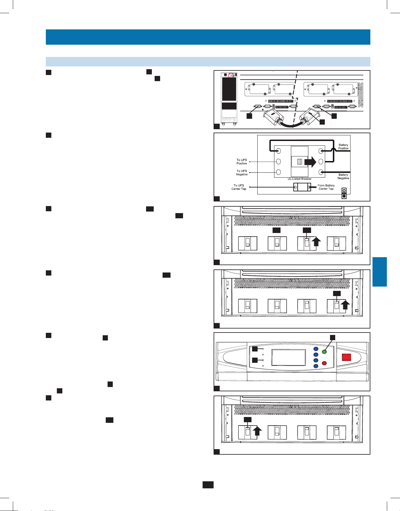
8-8 Start-Up Procedure (Parallel UPS—MUS)
• Connect the parallel configuration cable A (shipped with each
1
UPS) to the DB9 parallel configuration port B of each UPS
system. Note: Before starting up the Parallel UPS system, ensure
that the “Parallel ID” is different for each UPS and parallel group
is set to 2. See Section 10-5-5 for more details.
Refer to Section 6-8 or 6-9 for the appropriate settings of the
parallel port DIP switches and parallel cable connections.
1
• With each UPS system’s external battery cabinet connected, switch
2
on the external battery cabinet circuit breaker switch of each
battery cabinet.
2
3
• Confirm that the manual bypass breaker Q3 on each UPS system is
off. Switch on the bypass input circuit breaker switch Q2 of each
UPS system. After a brief initialization process, the LCD screen
will show “ON AUTO BYPASS” and the “BYPASS” LED will
illuminate.
B B
Q3
A
Q2
1
2
3
4
5
6
7
4
• Switch on the main input circuit breaker switch Q1 of each UPS
system.
5
• Press the ON button A of one of the UPS systems for 3 seconds
(until you hear a beep), then release the button. The inverter will
activate and synchronize with the bypass source. Press the ON
button for each of the other UPS systems for 3 seconds (until you
hear a beep), then release the button. When the inverter of each
UPS system is operating normally, they will automatically switch
from auto bypass mode to on-line (normal) mode at the same time.
The “BYPASS” LEDs B will turn off and the “NORMAL” LEDs
C
will illuminate.
6
• Check the output voltage of each UPS system. The phase voltage
deviation between each UPS system should be less than 5V. If the
phase deviation is within the acceptable range, switch on the output
circuit breaker switch Q4 of each UPS system. Note: For more
information on checking the output voltage of each UPS system,
see Section 10-4.
Output Manual
3
Bypass
Bypass
Input
Main
Input
8
Q1
9
Output Manual
4
Bypass
C
B
Bypass
Input
Main
Input
A
10
11
5
12
Q4
13
Output Manual
6
Bypass
Bypass
Input
Main
Input
14
25
12-212-93-3141.indb 25 12/28/2012 11:17:46 AM
Page 26
8 – Start-Up, Shutdown and Bypass (continued)
1
8-9 Shutdown Procedure (Parallel UPS—MUS)
Warning: The UPS system shutdown procedure will eliminate the AC power output for all loads. Before shutdown, confirm that all loads
2
are turned off or place the UPS systems in manual bypass mode (See Section 8-10) to keep loads powered by the bypass power path.
1
• For the UPS system you wish to shut down, press the OFF button
A
for 3 seconds (until you hear a beep), then release the button.
If the other UPS systems can support the connected equipment
3
4
5
6
loads alone, the UPS system that was turned off will shut down its
inverter and its LCD screens will read “LOAD NOT POWERED”.
The other UPS system’s LCD screen will read “ONLINE MODE”.
If the total connected equipment load is too large to be handled by
the remaining UPS systems, all UPS systems will shut down their
inverters and switch to bypass mode, and their LCD screens will
read “ON AUTO BYPASS”.
Confirm the UPS you wish to shut down is in bypass mode (amber
bypass LED B is on, LCD displays “ON AUTO BYPASS”).
2
• For the UPS system you wish to shut down, switch off the main
input circuit breaker switch Q1, then switch off the output circuit
breaker switch Q4.
B
1
A
Q1Q4
• For the UPS system you wish to shut down, switch off the bypass
3
7
input circuit breaker switch Q2.
8
4
• When the UPS system is completely shut down, the LCD screen
9
10
11
will be completely off. Wait until the power module fans power off
and the LCD display goes blank (this may take a minute or two).
Then, switch off the external battery cabinet circuit breaker switch
of each battery cabinet connected to the UPS you wish to shut
down.
Note: If the UPS system remains off for an extended period of time, it
should be turned on periodically to allow the batteries to recharge. The
UPS system should be turned on and the batteries should be recharged
at least one uninterrupted 24-hour period every 3 months. Failure
to recharge the batteries periodically may cause irreversible battery
damage.
Output Manual
2
Output Manual
3
4
Bypass
Bypass
Bypass
Input
Q2
Bypass
Input
Main
Input
Main
Input
12
13
14
26
12-212-93-3141.indb 26 12/28/2012 11:17:47 AM
Page 27
8 – Start-Up, Shutdown and Bypass (continued)
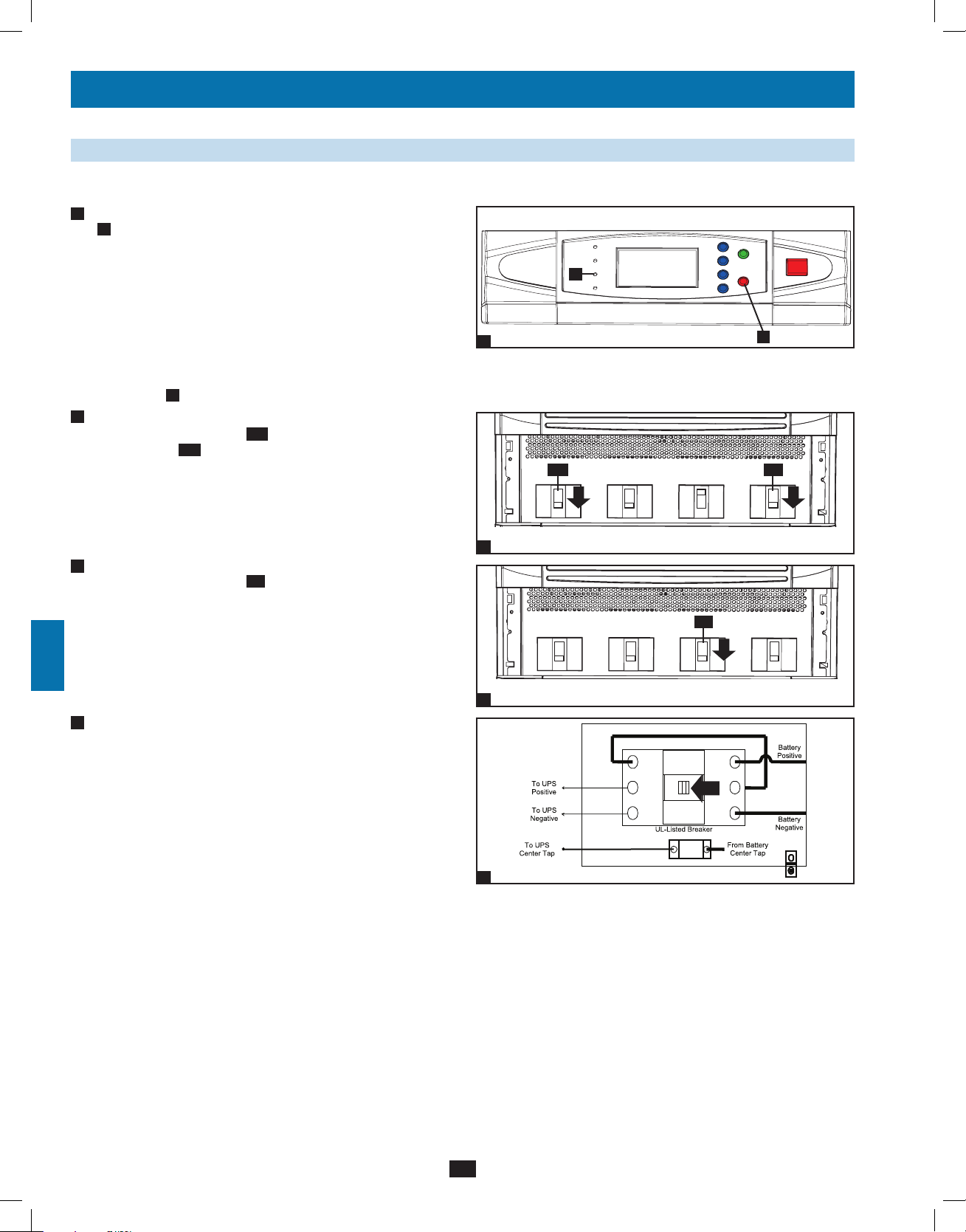
8-10 Switching to Manual Bypass Mode from Normal Mode Procedure (Parallel UPS—MUS)
Warning: When the UPS system is in manual bypass, the inverter shuts down. Connected equipment loads are powered by the bypass
power path and will not receive battery backup during a utility power failure or out of limits event.
• For the first UPS system you wish to transfer to manual bypass
1
mode, press the OFF button A for 3 seconds (until you hear
a beep), then release the button. If the other UPS systems can
support the connected equipment loads, the UPS system that was
turned off will shut down its inverter and its LCD screen will read
“LOAD NOT POWERED”. All other UPS systems’ LCD screens
will read “ONLINE MODE”. If the total connected equipment load
is too large to be handled by the remaining UPS systems, all UPS
systems will shut down their inverters and switch to bypass mode,
and their LCD screens will read “ON AUTO BYPASS”. Repeat
step 1 for each UPS system you wish to transfer to manual bypass
mode.
Confirm that all UPS systems are in auto bypass mode.
2
• Switch off the main input circuit breaker switch Q1 of each UPS
system.
1
A
Q1
1
2
3
4
5
3
• Switch on the manual bypass input circuit breaker switch Q3 of
each UPS system. The bypass power path will power the loads and
all LCD screens will read “ON MANUAL BYPASS”.
4
• Switch off the bypass input circuit breaker switch Q2 and the
output circuit breaker switch Q4 of each UPS system. Wait for the
power module fans and the LCD screen to turn off completely (this
may take a minute or two).
5
• Switch off the external battery cabinet circuit breaker switch of
each battery cabinet.
Output
2
Manual
Bypass
Q3
Bypass
Input
Main
Input
6
7
Output
3
Manual
Bypass
Bypass
Input
Main
Input
8
Q2Q4
9
Output
4
Manual
Bypass
Bypass
Input
Main
Input
10
11
6
• In this mode, only the manual bypass path (including the manual
5
12
bypass circuit breaker Q3), the load terminals of the output
circuit breaker switch Q4 and the terminal block B contain
hazardous voltage, allowing qualified service personnel to perform
maintenance or repair. Note: Qualified service personnel may
Q4 Q3
B
13
prefer to de-energize the UPS systems completely, depending
on local codes and the nature of the maintenance or repair. Use
of a parallel cabinet with system level maintenance bypass is
recommended.
12-212-93-3141.indb 27 12/28/2012 11:17:51 AM
27
6
14
Page 28
8 – Start-Up, Shutdown and Bypass (continued)
1
8-11 Switching to Normal Mode from Manual Bypass Mode (Parallel UPS—MUS)
• If the UPS systems have external battery cabinets connected,
1
2
3
4
5
switch on the external battery cabinet circuit breaker switch of
each battery cabinet for each UPS.
2
• Switch on the bypass input circuit breaker switch Q2 and the
output circuit breaker switch Q4 of each UPS system.
1
Q2Q4
6
• Confirm that all UPS systems are in manual bypass mode, then
3
switch off the manual bypass input circuit breaker switch Q3
of each UPS system. The LCD screen will read “ON AUTO
BYPASS”.
7
8
• Switch on the main input circuit breaker switch Q1 of each UPS
4
system.
9
• Press the ON button A of the first UPS system for 3 seconds (until
5
10
you hear a beep), then release the button. Press the ON button
for each of the remaining UPS system for 3 seconds (until you
hear a beep), then release the button. When the inverters of all
UPS systems are operating normally, they will switch to on-line
11
(normal) mode at the same time.
Output Manual
2
Output
3
Output
4
Bypass
Q3
Manual
Bypass
Manual
Bypass
Bypass
Input
Bypass
Input
Bypass
Input
Main
Input
Main
Input
Q1
Main
Input
A
5
12
13
14
28
12-212-93-3141.indb 28 12/28/2012 11:17:51 AM
Page 29
9 – Power Module Status and Replacement
Warning: Only authorized Tripp Lite service technicians with knowledge and operational training of this equipment
should install, repair or remove any system components, including power modules. Only power modules with the same
firmware versions may be placed within the same UPS system frame. Verify power module firmware version before
replacement. Permanent power module removal or addition can only be performed by Tripp Lite authorized service
technicians.
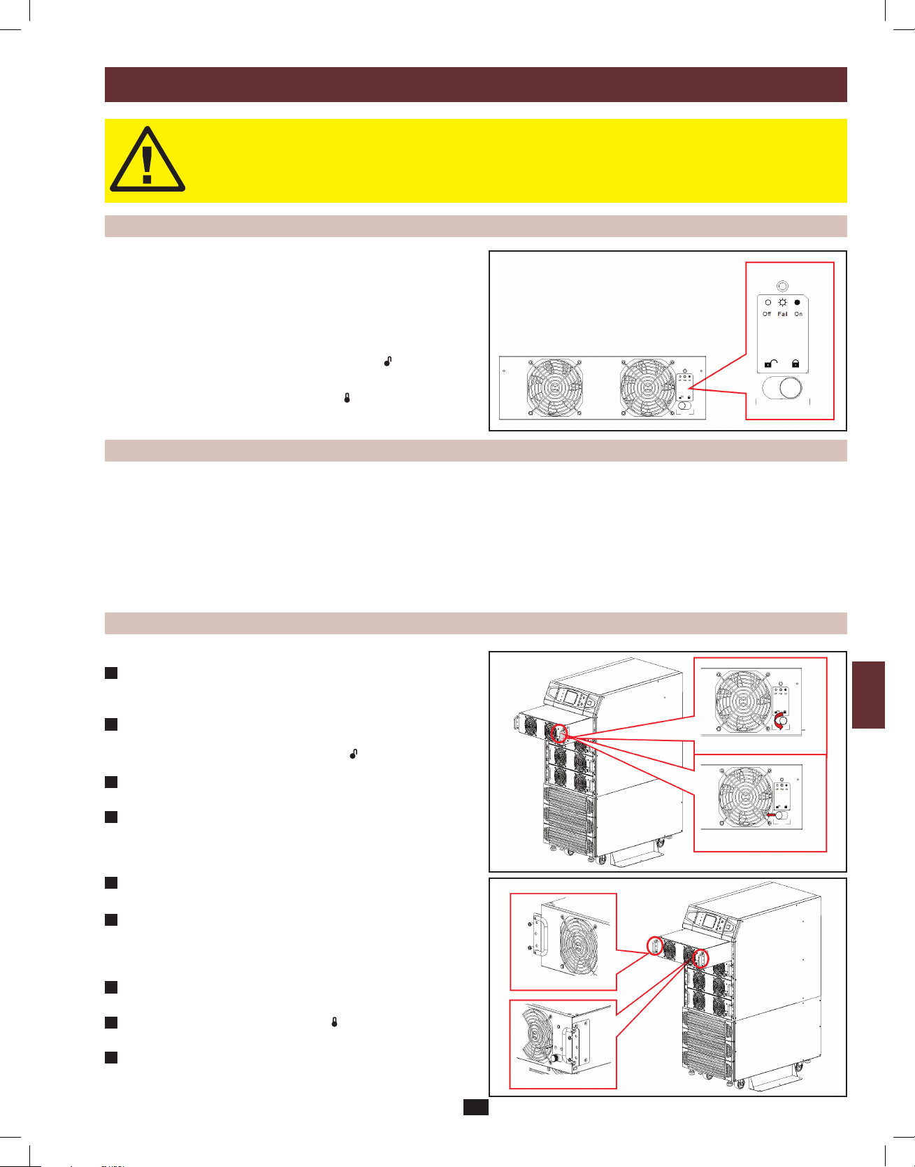
9-1 Power Module Features and Status
1
2
Each Power Module features an LED indicator to inform the user of its
status.
LED Indicator Statuses
“ON”—The power module is active and functioning properly.
“FLASHING”—The power module has failed and is offline.
“OFF”—When the locking latch is in “UNLOCKED” ( ) position, the
power module is inactive.
When the locking latch is in “LOCKED” ( ) position and the
main power is on, the power module has failed.
9-2 Preliminary Replacement Checklist
• BeforeremovingaPowerModule,ensurethattheremainingPowerModulescansupporttheconnectedload.
• VerifythatthePowerModuleneedsserviceorreplacementviaitsindividualLEDstatusindicator.
• DonotattempttoremovePowerModulesbyyourself.PowerModulesweigh30kg(66lb)andrequireatleasttwopeopleforproperhandling.
• PowerModulescanbereplacedinanyUPSOperatingMode.Itisnotnecessarytopowerloadsofforleavethemunprotected.Note: UPS must
be able to support load without the Power Modules to be replaced. If the UPS cannot handle the load once the Power Module is deactivated, an
overload will occur and the UPS will shut down.
• Replacepowermoduleswithsamefirmwareversiononly.
9-3 Replacement Procedure
To Remove Power Module
1. Remove the bezel cover of the Power Module you wish to
1
replace. Verify that there is a fault through the individual LED
status and UPS LCD screen.
2. Deactivate the Power Module by turning the spring-activated
2
knob of the locking latch counter-clockwise until it pops out.
Move the locking latch to “UNLOCKED” ( )
3
3. Use a screwdriver to remove the screws on either side of the
Power Module (total of 4).
4
4. With one person on either side of the Power Module, pull out and
lift the module from the UPS frame.
To Replace Power Module:
5
Verify power module replacement has the same firmware version
(as labeled).
With one person on either side of the repaired or new Power
6
Module, lift and align the Power Module into the appropriate slot
on the UPS. Slide the Power Module in until it is fully inside the
unit and seated flush with its brackets.
Use a screwdriver to fasten the screws on either side of the Power
7
Module (total of 4).
8
Move the locking latch to “LOCKED” ( ) position and turn
clockwise until it pops in. Power Module will activate.
9
Verify that the Power Module is activated via the status LED and
UPS LCD screen before replacing the bezel cover.
3
4
5
6
7
8
9
10
11
12
13
14
29
12-212-93-3141.indb 29 12/28/2012 11:17:53 AM
Page 30
10 – Display and Configuration
1
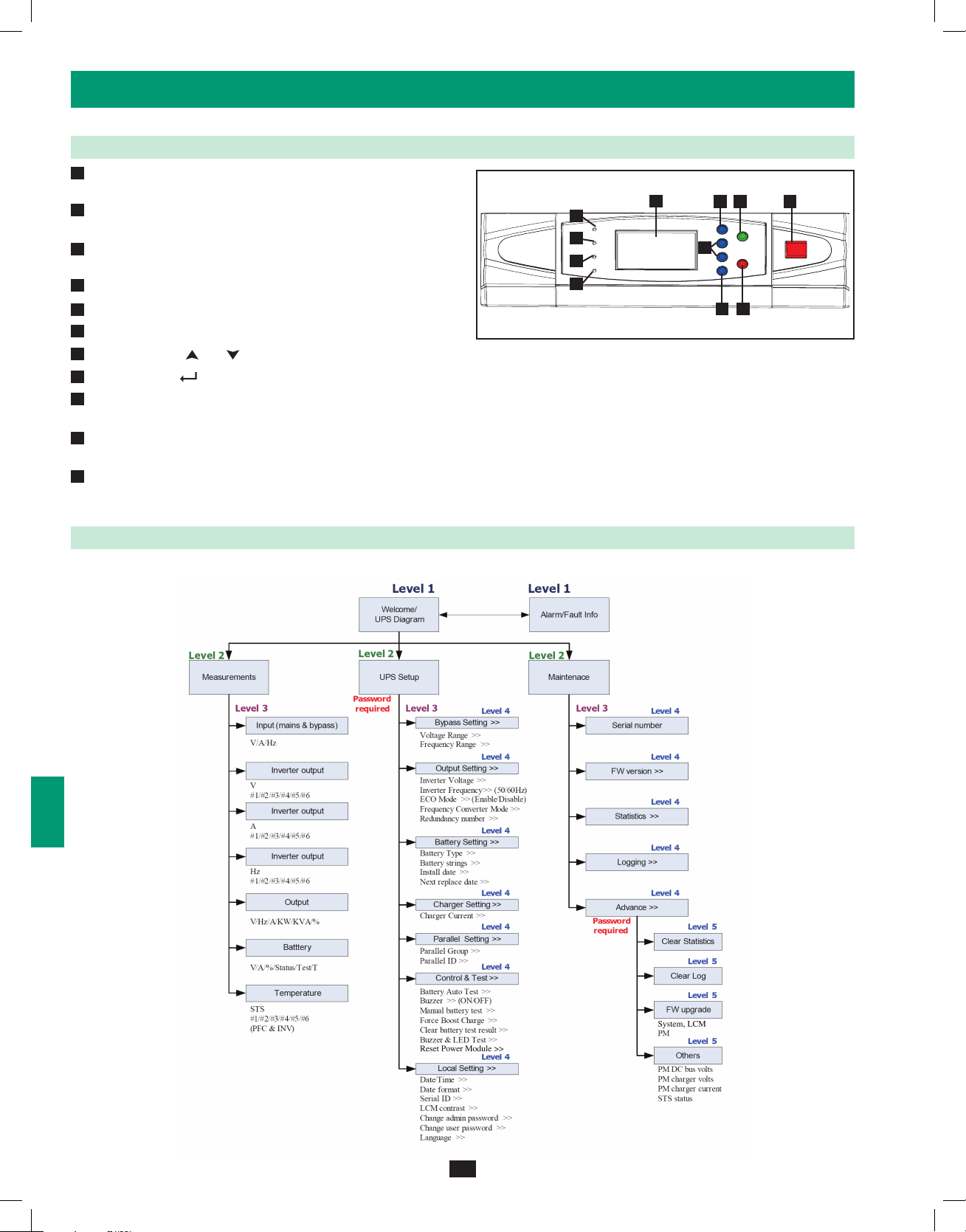
10-1 Control Panel Diagram
• “NORMAL” (Green) LED: Illuminated when the UPS input
A
2
3
4
5
6
power is normal.
B
• “BATTERY” (Amber) LED: Illuminated when the UPS is in
Battery Backup mode.
• “BYPASS” (Amber) LED: Illuminated when the UPS is in
C
Manual Bypass mode.
D
• “FAULT” (Red) LED: Illuminated when any fault occurs.
E
• LCD Status Display: Multi-language display.
F
• “ESC” (Escape) Button: Escape/Page Up.
G
• Scroll Buttons ( and ): Scroll cursor Up or Down.
H
• Enter Button ( ): Confirm settings.
I
• ON Button: Press and hold for 3 seconds to start up the UPS
(turns Inverter ON).
J
• OFF Button: Press and hold for 3 seconds to power OFF the
UPS (turns Inverter OFF).
K
• “EPO” (Emergency Power Off) Button: Pressing the EPO
button will completely remove power from the UPS output.
E
A
B
C
D
Control Panel
F
I
G
J
H
K
10-2 Display Hierarchy
The Tripp Lite SU120KX2 UPS features a user-friendly LCD screen to show messages and display UPS Status screens.
7
8
9
10
11
12
13
14
30
12-212-93-3141.indb 30 12/28/2012 11:17:58 AM
Page 31

10 – Display and Configuration (continued)
10-3 Default Display
• After the UPS system starts up and completes the self-test, the
1
LCD status screen will show the default display. The default
display includes a status message and diagram that shows the
operational status of the UPS system.
When any event occurs, you will see the sign “!” flashes. You can press “ ” to see the details. For example:
1
2
3
4
5
1
6
Press “ ” again to go to the next message. If there is no further message, the screen will return to the default screen.
10-3-1 Status Display
• The UPS system output is off and the connected equipment loads
1
are not powered. This condition may be due to automatic UPS
shutdown or manually switching off the output circuit breaker
switch.
Possible causes:
• The UPS automatically shuts down by itself.
• Manually switch off the output circuit breaker.
7
8
9
10
11
12
13
14
1
31
12-212-93-3141.indb 31 12/28/2012 11:18:00 AM
Page 32

10 – Display and Configuration (continued)
1
10-3-1 Status Display (continued)
• The loads are supplied by bypass source due to initial startup of
2
2
3
4
5
6
the UPS.
3
• The UPS is starting up by battery power.
2
7
8
9
4
• The UPS system is in auto bypass mode. Connected equipment
loads will lose power if the bypass power source fails.
10
11
12
3
13
4
14
32
12-212-93-3141.indb 32 12/28/2012 11:18:00 AM
Page 33

10 – Display and Configuration (continued)
10-3-1 Status Display (continued)
5
• The UPS system is operating in online (normal) mode. Connected
equipment loads will receive battery backup power if the mains
(utility or generator) power source fails.
6
• The UPS is in battery backup mode. The loads are supplied by
battery power.
1
2
3
4
5
5
6
7
• The UPS is performing the “battery test”.
7
8
6
9
10
11
12
7
13
14
33
12-212-93-3141.indb 33 12/28/2012 11:18:01 AM
Page 34

10 – Display and Configuration (continued)
1
10-3-1 Status Display (continued)
• The UPS system is operating in economy mode, and connected
8
2
3
4
5
6
equipment loads are being powered by the bypass source.
• The UPS system is in manual bypass mode in order to allow
9
qualified service personnel to perform maintenance or repair on
the UPS system. Connected equipment loads will lose power if
the bypass power source fails.
8
7
8
9
10-4 Main Menu
From the default display, press the enter button ( ) to access the main
10
menu. Press the scroll down button ( ) or the scroll up button
( ) to move the cursor. Press the enter button ( ) to select one of the
available menu options.
11
12
9
13
14
34
12-212-93-3141.indb 34 12/28/2012 11:18:02 AM
Page 35

10 – Display and Configuration (continued)
10-4 Main Menu (continued)
UPS System “Measure Menu”. Screens shown below are used to illustrate available fields and do not show actual data.
1. Press the enter button ( ) to select “MEASURE” from the main menu.
2. Use the scroll buttons ( or ) to scroll through the available data screens. Press the “ESC” button to return to the previous menu.
1
2
3
4
5
6
7
8
9
10
11
12
13
14
35
12-212-93-3141.indb 35 12/28/2012 11:18:03 AM
Page 36

10 – Display and Configuration (continued)
1
10-5 UPS Setup
Before changing the setting of each SETUP, you have to login first.
2
3
4
5
• Accessing the UPS system setup menu requires a password. From
1
6
7
the login screen, press the enter button ( ) to select whether to
log in as an administrator or user.
ADMINISTRATOR:
Qualified service personnel
User:
The authorization is only to check the parameter but not to
configure.
8
9
2
• The password consists of 4 numerals. Press the scroll down
button ( ) or the scroll up button ( ) to select the first numeral,
10
then press the enter button ( ) to enter the numeral choice. After
entering the last numeral, press the enter button ( ) to confirm
the password choice. The default user password is 0000. The
default administrator password is 0000. Only qualified service
personnel should have access to the administrator password.
11
12
13
1
2
14
36
12-212-93-3141.indb 36 12/28/2012 11:18:03 AM
Page 37

10 – Display and Configuration (continued)
10-5 UPS Setup (continued)
• If the password is wrong, press ” ” to reselect.
3
10-5-1 Bypass Setup
• Enter the UPS system setup menu. Use the scroll buttons ( , )
1
to move the cursor to “BYPASS SETUP”, then press the enter
button ( ).
1
2
3
4
5
3
6
2
• From the “VOLTAGE RANGE” screen, use the scroll buttons
( , ) to select a bypass voltage range and press the enter button
( ) to confirm the setting. [Range= 8% to 15%]
7
8
9
1
10
11
12
13
2
14
37
12-212-93-3141.indb 37 12/28/2012 11:18:04 AM
Page 38

10 – Display and Configuration (continued)
1
10-5-1 Bypass Setup (continued)
• From the “FREQUENCY RANGE” screen, use the scroll buttons
3
2
3
4
5
6
( , ) to select a bypass frequency range and press the enter
button ( ) to confirm the setting. [Range= 1 to 5]
Press “ESC” to return to the “UPS SETUP” menu.
10-5-2 Output Setup
Use “ ” or ” ” to select “OUTPUT SETUP”, then press ” ” to
confirm.
3
7
• Enter the UPS system setup menu. Use the scroll buttons ( , )
1
8
to move the cursor to “OUTPUT SETUP”, then press the enter
button ( ).
All parameters in this segment can only be changed when UPS is in “Bypass Mode”.
9
10
11
12
1
13
14
38
12-212-93-3141.indb 38 12/28/2012 11:18:05 AM
Page 39

10 – Display and Configuration (continued)
10-5-2 Output Setup (continued)
Output Voltage
2
Do not change the default voltage setting as it will negatively
affect UPS performance.
1
2
3
4
3
From the “FREQUENCY” screen, use the scroll buttons ( , )
to select the desired setting and press the enter button ( ) to
confirm the setting. Note: The output frequency setting is only
used when the UPS system starts from battery or when frequency
converter mode is enabled.
4
From the “ECO MODE” screen, use the scroll buttons
( , ) to select the desired setting and press the enter button
( ) to confirm the setting.
2
6
7
8
5
3
9
10
11
12
4
13
14
39
12-212-93-3141.indb 39 12/28/2012 11:18:05 AM
Page 40

10 – Display and Configuration (continued)
1
10-5-2 Output Setup (continued)
From the “FREQ CONVERTER MODE” screen, use the scroll
5
2
3
4
buttons ( , ) to select the desired setting and press the enter
button ( ) to confirm the setting. In frequency converter mode,
the UPS will convert the incoming electrical power frequency
to a different output frequency. Therefore, 60Hz can change to
50Hz output or 50Hz input can change to 60Hz output. When
in frequency converter mode, bypass power is not an available
source (the UPS will not transfer to bypass).
5
6
Redundancy
Use “ ” or ” ” to select the desired number of modules for
6
7
8
redundancy (usually one) for redundancy, then press ” ” to
confirm.
This feature allows the user to determine an acceptable power
output limit to guarantee a redundancy of N+1. When this feature
is enabled, the UPS will send an alarm when power usage exceeds
80% of the “non-redundant” power modules while maintaining
the number of redundant power modules set. For example, on a
120kVA UPS, if a Redundancy Setup is set to “1 Power Module”,
the UPS will trigger an alarm when you exceed 80% of 100kVA
as to guarantee one power module for N+1 redundancy.
Press “ESC” to return to the “UPS SETUP” menu.
9
10-5-3 Battery Setup
Use “ ” or ” ” to select “BATTERY”, then press ” ” to confirm.
10
5
6
All parameters in this segment can only be changed when UPS is in “Bypass Mode”.
11
12
13
14
40
12-212-93-3141.indb 40 12/28/2012 11:18:06 AM
Page 41

10 – Display and Configuration (continued)
10-5-3 Battery Setup (continued)
Enter the UPS system setup menu. Use the scroll buttons ( , )
1
to move the cursor to “BATTERY SETUP”, then press the enter
button ( ).
At UPS startup, you must enter information about the battery,
including amp hour rating, number of strings and charger current.
Use the following formulas as a guide.
TYPE (AH) – The AH rating for external batteries is equal
to the number after the “V” in the model name. For example,
BP480V78= 78 AH. If more than one external battery cabinet is
used, total the AH ratings for all of the external battery cabinets
connected to the UPS.
BAT STRINGS – This is the number of external battery cabinets/
chains connected to the UPS. Available entries are 1 through 4.
CHARGER CURRENT – See Section 10-5-4 for information
about setting the charger current.
From the “EXT BAT TYPE” screen, use the scroll buttons ( ,
2
) to select the desired settings and press the enter button ( )
to confirm the settings. Note: See step 1 for additional guidance
on AH settings.
SPECIAL (x2) BP480V40C= 80 AH
BP480V55 = 55 AH
BP480V78 = 78 AH
BP480V103 = 103 AH
BP480V140 = 140 AH
1
2
3
4
1
5
6
7
3
Battery Strings
Use “ ” or “ ” to select the desired number of battery strings,
then press “ ” to confirm. Note: See step 1 for information
about battery string settings.
8
2
9
10
11
12
3
13
14
41
12-212-93-3141.indb 41 12/28/2012 11:18:07 AM
Page 42

10 – Display and Configuration (continued)
1
10-5-3 Battery Setup (continued)
From the “INSTALL DATE” screen, use the scroll buttons ( , )
4
2
3
4
to select the desired settings and press the enter button ( ) to
confirm the settings. At selected date, the UPS will send the alarm
message “Battery Needs Replacement”.
5
5
Battery Next Replace Date
6
Use “ ” or ” ” to set the next replace date, then press ” “ to
confirm. (When the selected date is reached, the UPS will alarm
and a message will be shown in the LCD display.)
7
8
9
6
From the “TEST DURATION” screen, use the scroll buttons
( , ) to select the desired setting and press the enter button
10
( ) to confirm the setting.
Press “ESC” to return to the “UPS SETUP” menu.
4
5
11
12
13
6
14
42
12-212-93-3141.indb 42 12/28/2012 11:18:08 AM
Page 43

10 – Display and Configuration (continued)
10-5-4 Charger Setup
Use “ ” or ” ” to select “CHARGER”, then press ” ” to confirm.
1
From the “CHARGER CURRENT” screen, use the scroll buttons
( , ) to select the desired setting and press the enter button
( ) to confirm the setting.
Each internal power module has a 5-amp maximum charger.
Charger current can be set from a minimum 2 amps total to a
maximum of 5 amps (or max current determined by a charging
rate ≤ C/4 in a per-power-module base, whichever is smaller)
multiplied by the number of modules. The SU120KX2 with six
internal power modules has a charger current range of 2-30
amps. Set the charger current value based on the size of the
battery system. See Section 10-5-3 for more information about
determining the size of the battery system.
Warning: Setting the charger current too high may damage
batteries and reduce their operational lifespan. Consult the
factory or your authorized Tripp Lite service technician for
guidance before changing the default setting.
2
Press “ ” or ” ” to change the charging current, then press
” ” to confirm.
Press “ESC” to return to the “UPS SETUP” menu.
1
2
3
4
5
1
6
7
8
2
9
10
11
12
13
14
43
12-212-93-3141.indb 43 12/28/2012 11:18:08 AM
Page 44

10 – Display and Configuration (continued)
1
10-5-5 Parallel Setup
Use “ ” or ” ” to select “PARALLEL”, then press ” ” to confirm.
2
1
Use “ ” or ” ” to select the desired item, then press ” ” to
confirm.
3
4
10
5
1
Parallel Group
2
The parallel group setting tells the UPS that it is operating in
6
parallel. System configuration Group 1 is the default setting. See
Section 6 – Wiring for wiring considerations. Note: Possible
settings are 1 or 2.
7
8
9
Parallel ID
3
Identifies the UPS number (1-8) within the group. When
paralleling UPS systems, each must have a unique Parallel ID. Up
to four (4) SU120KX2 UPS systems may be paralleled.
2
Press “ESC” to return to the “UPS SETUP” menu.
11
12
13
3
14
44
12-212-93-3141.indb 44 12/28/2012 11:18:09 AM
Page 45

10 – Display and Configuration (continued)
10-5-6 Control & Test Setup
Use “ ” or ” ” to select “CONTROL & TEST”, then press ” ” to
confirm.
Use “ ” or ” ” to select the desired item, then press ” ” to
1
confirm.
1
2
3
4
Battery Auto Test
2
Use “ ” or ” ” to select the desired item, then press ” ” to
confirm. Allows for scheduling of a battery test frequency for the
duration selected in Section 10-5-3 step 6.
Buzzer
3
Use “ ” or ” ” to select enable or disable the buzzer, then press
” ” to confirm. Silences the audible alarm.
1
6
7
8
5
2
9
10
11
12
3
13
14
45
12-212-93-3141.indb 45 12/28/2012 11:18:10 AM
Page 46

10 – Display and Configuration (continued)
1
10-5-6 Control & Test Setup (continued)
Manual Battery Test
4
2
3
4
Press ” ” to execute “MANUAL BAT TEST”. Allows you to
run a battery test at a non-scheduled time at the user’s discretion.
(This item is only accessible by the administrator! The password
will be needed.)
The duration of the test can be chosen using Section 10-5-3,
step 6.
10
5
4
Force Boost Charge
5
Press ( ) to execute “FORCE BOOST CHARGE” Enables
6
7
activating the boost charge which is at a voltage of 5% higher than
the nominal setting. Warning: Boosting battery charge rate for
extended periods may damage the battery system.
(This item is only accessible by the administrator! The password
will be needed.)
8
9
6
Clear Battery Test Result
Press “ ” to execute “CLR BAT TEST RESULT”. This will
clear all battery test results in log.
Note: Clearing event logs may invalidate warranty claims. All
warranty claims must be accompanied by supporting event log
information.
5
11
12
13
6
14
46
12-212-93-3141.indb 46 12/28/2012 11:18:11 AM
Page 47

10 – Display and Configuration (continued)
10-5-6 Control & Test Setup (continued)
Select “BUZZER AND LED TEST” to initiate test of the control
7
panel LEDs and audible alarm. You must enter the administrator
password to confirm the operation.
Press “ESC” to return to the “UPS SETUP” menu.
10-5-7 Local Setup
Use “ ” or ” ” to select “LOCAL SETUP”, then press ” ” to
confirm.
1
Use “ ” or ” ” to select the desired item, then press ” ” to
confirm.
1
2
3
4
5
7
6
2
From the “DATE/TIME CHANGE” screen, use the scroll buttons
( , ) to select the desired settings and press the enter button
( ) to confirm the settings. Note: Changing this setting does not
require an administrator login – a user login is sufficient.
7
8
9
1
10
11
12
13
2
14
47
12-212-93-3141.indb 47 12/28/2012 11:18:11 AM
Page 48

10 – Display and Configuration (continued)
1
10-5-7 Local Setup (continued)
Date Format
3
2
3
4
5
6
Use “ ” or ” ” to change the date format, then press ” ” to
confirm.
(This item is user accessible! )
From the “SERIAL COM ID” screen, use the scroll buttons ( ,
4
) to select the desired serial port ID and press the enter button
( ) to confirm the setting. Note: This setting does not apply to
standard RS-232 connections. It only applies for RS-485/RS-422
communications.
3
10
11
12
7
8
9
This ID is not used for standard RS232 connection. If using the RS485/RS422
converter of other brands to connect to RS232 port, the ID can be set to 00, 01…….99.
5
LCD Contrast
Use “ ” or ” ” to set the contrast of LCD screen, then press
” ” to confirm. Changes the contrast ratio of the LCD.
(This item is user accessible!)
1 is the lowest and 5 is the highest level.
4
13
14
5
48
12-212-93-3141.indb 48 12/28/2012 11:18:12 AM
Page 49

10 – Display and Configuration (continued)
10-5-7 Local Setup (continued)
Administrator Password
6
From the “PASSWORD CHANGE” screen, use the scroll buttons
( , ) and the enter button ( ) to select the desired menu
choice. Use the scroll buttons ( , ) to select the desired settings
and press the enter button ( ) to confirm the settings. Note:
The administrator password should be used by qualified service
personnel only.
1
2
3
4
7
User Password
The password consists of 4 digits. From the “PASSWORD
CHANGE” screen, use the scroll buttons ( , ) and the enter
button ( ) to select the desired menu choice. Use the scroll
buttons ( , ) to select the desired settings and press the enter
button ( ) to confirm the settings.
Language
8
Use “ ” or ” ” to select the language of LCD screen, then press
” ” to confirm. Select from the 10 languages with which the
LCD display can be configured.
Caution: Changing the LCD display language will change all
display functions to the selected language format.
6
6
7
8
5
7
9
10
Press “ESC” to return to the “UPS SETUP” menu.
12
11
8
13
14
49
12-212-93-3141.indb 49 12/28/2012 11:18:13 AM
Page 50

10 – Display and Configuration (continued)
1
10-6 Maintenance
Use “ ” or ” ” to select ”MAINTENANCE” in the main menu, then
2
press ” ” to confirm.
The first item is the series number of the UPS unit.
1
Use “ ” or ” ” to select the desired item, then press ” ” to
confirm.
3
4
5
Firmware Version
2
6
7
Use “ ” or ” ” to select the F/W version item, then press ” ”
to confirm.
(The display will show the firmware version of the system and
each power module.)
1
10
11
12
13
8
9
2
3
Statistics
Use “ ” or ” ” to read the statistics data, then press ” ” to
confirm.
(The display will show the “counts on battery”, “counts on
bypass” and “total operation time”.)
3
14
50
12-212-93-3141.indb 50 12/28/2012 11:18:14 AM
Page 51

10 – Display and Configuration (continued)
10-6 Maintenance (continued)
Event Log
4
Use “ ” or ” ” to read the event log, then press” ” to
confirm.
Advanced
5
Use “ ” or ” ” to select the “ADVANCED” item, then press
” ” to confirm.
The “ADVANCED” item includes “clear statistics”, “clear event
log” “firmware upgrade” and “other status monitor for service”.
(This item is only accessible by the administrator! The password
will be needed.)
Warning: Clearing or erasing the event log may invalidate
warranty claims. All warranty claims must be accompanied
by supporting event log information.
1
2
3
4
5
4
6
7
8
Press “ESC” to return to the “UPS SETUP” menu.
5
9
10
11
12
13
14
51
12-212-93-3141.indb 51 12/28/2012 11:18:14 AM
Page 52

11 – Communications
1
Note: The communications connections described in this section are optional. The UPS system will function properly without these connections.
11-1 Communications Interfaces
2
SNMPWEBCARD Slot
3
4
Input Dry Contact
5
6
Interface
Parallel
Configuration Port
7
Note: The following connectors are provided with the UPS: P1, P2 and a 12 position strip for the output dry contacts. P3 and P7 are only shipped
with the optional battery cabinets, which include battery monitoring circuits.
Parallel
Configuration Port
DIP
Switches
Output Dry
Contact Interface
RS-232
Serial Port
11-2 SNMPWEBCARD Slot
8
Remove the cover panel to install a Tripp Lite SNMPWEBCARD or MODBUSCARD accessory. These accessories provide a network interface
for the UPS system and enable remote monitoring and control via Modbus, SNMP, Web browser or telnet. Visit www.tripplite.com for more
information about ordering.
9
11-3 Input Dry Contact Interface
The input dry contact interface receives contact-closure signals that allow the UPS system to receive commands and monitor external battery
conditions:
P1—Remote Emergency Power Off (EPO) (See Section 11-4.)
10
P2—Auxiliary Dry Contact Inputs (2 sets) (Input Contact A: Pin 1,2 Rated for 12V DC minimum 0.1A (nominal); Input Contact B: Pin 3,4 Rated
for 12V DC minimum 0.1A (nominal). See Section 11-5.)
P3—External Battery Cabinet Temperature 1 (Temperature Sensor Inputs from external battery cabinets. See Section 11-6.)
P4—External Battery Cabinet Temperature 2 (Temperature Sensor Inputs from external battery cabinets. See Section 11-6.)
11
P5—External Battery Cabinet Temperature 3 (Temperature Sensor Inputs from external battery cabinets. See Section 11-6.)
P6—External Battery Cabinet Temperature 4 (Temperature Sensor Inputs from external battery cabinets. See Section 11-6.)
P7—External Battery Status (For use with battery status cable supplied with external battery cabinets-BP480V26B or BP480V40C.)
12
Note: Do not apply voltages to the REPO contacts or auxiliary dry contacts. Damage to the UPS may result. For the REPO, the switch must be
latching in order to keep output power OFF from the UPS output.
13
14
52
12-212-93-3141.indb 52 12/28/2012 11:18:14 AM
Page 53

11 – Communications (continued)
11-4 Remote Emergency Power Off (EPO) Circuit Diagram
The Remote Emergency Power Off (EPO) input connection (P1) allows you to connect the UPS system to your facility’s EPO circuit. Connecting
the UPS system to the EPO circuit enables remote emergency shutdown of the UPS system’s output. Connect EPO input to a user-supplied remote
switch, following the circuit diagram below. This contact is normally open. User supplied REPO button must be latching type in a closed position.
When opened, the UPS goes to bypass. The inverter must then be restarted by pressing the ON button to return to on-line mode. Contact rated for
12V DC minimum, 0.1A (nominal).
1
2
P1
DC
USER-SUPPLIED
REPO - N.O. LATCHING SWITCH
11-5 Auxiliary Dry Contact Input Circuit Diagram
The auxiliary dry contact input connections (P2) allow the UPS system to receive external signals.
INPUT DRY A (P2, pins 1 and 2) is utilized with generator controls. If required, as the generator starts up, closing the normally open (N.O.)
INPUT DRY A contact will cause the UPS to limit the DC charging current to less than half of its settings. Once the INPUT DRY A contact is
opened, DC charging current will return to its normal set functions.
INPUT DRY B (P2, pins 3 and 4) is utilized for remote shutdown within 60 seconds of its activation. Closing INPUT DRY B contact will begin the
UPS shutdown. Opening INPUT DRY B contact will disable the shutdown sequence. Repeated open/close sequencing of INPUT DRY B contact
should be avoided as damage to the UPS may result. A normally open (N.O.) latching type contact is therefore recommended for INPUT DRY B.
These contacts are normally open. External contacts rated for 12V DC minimum, 0.1A (nominal).
INPUT
DRY A
DC
3
4
5
6
7
8
INPUT
DRY B
DC
P2
USER-SUPPLIED
INPUT N.O. CONTACTS
11-6 External Battery Cabinet Temperature Inputs
The external battery cabinet temperature input connections (P3, P4, P5, P6) allow the UPS system to receive signals from an optional accessory
that monitors the temperature of external battery cabinets. Visit www.tripplite.com/support for more information.
11-7 External Battery Status Input
The external battery cabinet status input connection (P7) allows the UPS system to receive external battery cabinet status signals through an
optional cable. Pin 1 = +12V; Pin 2 = detection cable connected; Pin 3 = battery cabinet breaker status (signal active= breaker on; signal inactive =
off); Pin 4 = reserved; Pin 5 = reference voltage. Visit www.tripplite.com/support for more information.
9
10
11
12
13
14
53
12-212-93-3141.indb 53 12/28/2012 11:18:15 AM
Page 54

11 – Communications (continued)
1
11-8 Output Dry Contact Interface Detail
The UPS system has six dry contact output connections. These contacts can be normally open or normally closed.
2
Default Messages
Contact Message Description
Pin 1-2 Load on inverter The UPS system is working normally.
3
Pin 3-4 Load on auto bypass The UPS system is in bypass mode.
Pin 5-6 Main input failure with load on inverter Utility power is absent (blackout) or abnormal. The UPS system is in battery backup mode.
Pin 7-8 Battery low The UPS system is in battery backup mode, and battery voltage is lower than 220V.
Pin 9-10 Bypass input abnormal The bypass input is abnormal (frequency / phase).
4
Pin 11-12 Battery test failure The battery voltage is lower than the reference value.
Optional Messages
5
Message Description
Internal communication failure Communication with one of the internal components is not normal.
External parallel communication failure In a parallel redundancy installation, the parallel communication is not normal.
Output overload warning/shutdown The load exceeds the capacity of the UPS system.
6
Power module fault shutdown The UPS system has shut down due to an internal power module failure.
Power module warning An internal power module has an error, but the UPS system can still function normally.
EPO activated The UPS system’s output is disabled by the emergency power off (EPO) function.
Load on manual bypass The UPS system is in manual bypass mode.
7
Battery cabinet over temperature warning/shutdown The temperature of the external battery cabinet is too high.
Output voltage abnormal The UPS system’s output voltage is too high or too low.
Battery needs replacement According to the data in the “BAT DATE SETTING”, the UPS system is overdue for battery
replacement. (See Section 10-5-3 for more information.)
8
Bypass over temperature warning/shutdown The temperature of the bypass “static transfer switch” is too high.
Battery ground fault The battery has a grounding error.
Bypass static switch fault The bypass “static transfer switch” is abnormal.
9
Note: If you require optional messages to be enabled, contact your authorized Tripp Lite service group.
10
11
12
13
14
54
12-212-93-3141.indb 54 12/28/2012 11:18:15 AM
Page 55

11 – Communications (continued)
11-9 Output Dry Contact Circuit Diagram
The UPS system has six dry contact output connections. These
contacts can be normally open or normally closed. Contacts are rated
for 250V AC/28V DC; 8A.
1
2
3
4
OUTPUT
DRY CONTACT
11-10 RS-232 Serial Port Circuit Diagram
The RS-232 DB9 serial port connects the UPS system to a workstation
or server (cable included). By communicating with the UPS system
through this port, Tripp Lite’s PowerAlert UPS management software
(included) can monitor and control the UPS system. PowerAlert also
serves as an SNMP proxy allowing the UPS system to appear as an
SNMP-manageable device on the network.
RS-232 signals and operations include: load level, battery status, battery
level, operation mode, AC input voltage, AC output voltage, AC input
frequency, internal temperature, set shut-down delay time, enable/
disable alarm and remote shutdown.
5
6
7
8
9
10
11
Hardware
Baud Rate: 2400 BPS
Data Length: 8 bits
Stop Bit: 1 bit
Parity: NONE
Pin Assignment
Pin 2: TXD (Transmit Data)
Pin 3: RXD (Receive Data)
Pin 5: GND (Signal Ground)
12
13
11-11 Parallel Configuration Port
The parallel configuration port allows the UPS system to be connected to another UPS system of identical type and capacity for use in a parallel
(1+1) configuration for increased capacity or increased fault-tolerance. Warning: Use only the parallel configuration cable that is included
with the UPS system. Attempting to use an incompatible cable may damage the UPS systems and create a serious risk of personal injury
and property damage.
55
12-212-93-3141.indb 55 12/28/2012 11:18:16 AM
14
Page 56

12 – Specifications
1
12-1 UPS System Technical Specifications
2
Input
3
4
Output
5
6
Audible Warning
Display
7
Remote
Interface
8
9
Others
10
11
Overall
12
Capacity 120KVA/96KW
Rating Voltage V
Voltage Regulation % <70% Full Load: -48/+20 (at 230/400V); Full load: -25/+20 (230/400V)
Input Current Harmonic Distortion (Full
Load)
PFC (Full Load) > 0.99
Frequency Hz 50 / 60
Frequency Tolerance Hz 45 ~ 65
Output Voltage V 220/380, 230/400, 240/415 (3Φ 4W+Earth)
Output Frequency Hz 50 / 60
Total Harmonic (Linear Load) % ≦3
Voltage Regulation Static % ±1
Dynamic % 7 (Max Deviation for 10% ~ 90% Linear Load)
Frequency Regulation Interior Oscillator Hz ±0.05
Synchronized % ±5
Overload ≦125%: 10 minutes ; ≦150%: 1minute
Battery Backup Intermittent
UPS Abnormal Continuous
LED UPS status: Normal, Bypass, Backup and Fault
LCD
Monitor
Control Remote control the Inverter and alarm, setup password and auto-dial warning
Standard RS232, Dry Contact Output/Input
Optional
Parallel Configuration Up to 4 UPS systems of the same capacity for redundancy capacity
EPO Standard (Local and Remote)
SRAM Event Log Yes (500 records)
Parameter Configuration Yes
Hot Standby Installation Feasible
Battery Temperature Compensation Optional
Battery Cold Start Standard
Efficiency (at full load)
Transfer Time ms 0
Operating Temperature °C 0~40
Humidity (Non-Condensing) % 90
Noise (@ 1 m) dBA ≤70
Dimension Width mm 520
Weight Kg 379
Normal % 94
ECO % 97
Depth mm 975
Height mm 1695
% < 4
Input/Output, Bypass, Inverter, Frequency, Loading and Battery voltage, current,
UPS abnormal message and intelligent self diagnostics
Monitor up to 31 PCs, Graphically display records and historical data and
SNMP card, Modbus card, Relay I/O control card, Environmental sensor box,
220/380, 230/400, 240/415
(3Φ 4W+PE)
Fault records retrieved
SNMP+5 Ports Hub
12-2 UPS System Floor Loading Table
13
Model SU120KX
Weight 379 kg
Floor Loading 748 kg/m²
14
56
12-212-93-3141.indb 56 12/28/2012 11:18:16 AM
Page 57

13 – Storage and Service
Storage
The UPS system must be stored in a clean, secure environment with a temperature less than 40° C (104° F) and a relative humidity less than
90% (non-condensing). Store the UPS system in its original shipping container if possible. If installation occurs more than 6 months after
you receive the UPS system, recharge the batteries for at least 24 hours prior to use. Do not rely on the UPS system to provide backup power
to connected equipment until the batteries are fully charged. Note: If the UPS system remains off for an extended period of time, it should be
turned on periodically to allow the batteries to recharge. The UPS system should be turned on and the batteries should be recharged at least one
uninterrupted 24-hour period every 3 months. Failure to recharge the batteries periodically may cause irreversible battery damage.
Service
Your Tripp Lite product is covered by the warranty described in this manual. A variety of Extended Warranty and On-Site Service Programs are
also available from Tripp Lite. For more information on service, visit www.tripplite.com/support. Before returning your product for service, follow
these steps:
1. Review the installation and operation procedures in this manual to insure that the service problem does not originate from a misreading of the
instructions.
2. If the problem continues, do not contact or return the product to the dealer. Instead, visit www.tripplite.com/support.
3. If the problem requires service, visit www.tripplite.com/support and click the Product Returns link. From here you can request a Returned
Material Authorization (RMA) number, which is required for service. This simple on-line form will ask for your unit’s model and serial
numbers, along with other general purchaser information. The RMA number, along with shipping instructions will be emailed to you. Any
damages (direct, indirect, special or consequential) to the product incurred during shipment to Tripp Lite or an authorized Tripp Lite service
center is not covered under warranty. Products shipped to Tripp Lite or an authorized Tripp Lite service center must have transportation charges
prepaid. Mark the RMA number on the outside of the package. If the product is within its warranty period, enclose a copy of your sales receipt.
Return the product for service using an insured carrier to the address given to you when you request the RMA.
1
2
3
4
5
6
7
8
9
10
11
12
13
14
57
12-212-93-3141.indb 57 12/28/2012 11:18:16 AM
Page 58

14 – Warranty
1
Limited Warranty
Seller warrants this product, if used in accordance with all applicable instructions, to be free from original defects in material and workmanship for a period of 2 years (except U.S., Canada and Mexico:
1 year) from the date of initial purchase. If the product should prove defective in material or workmanship within that period, Seller will repair or replace the product, in its sole discretion. Service under
this Warranty includes parts and Tripp Lite service center labor. On-site service plans are available from Tripp Lite through authorized service partners (in most areas). Visit www.tripplite.com for details.
International customers should contact Tripp Lite support at intlservice@tripplite.com.
2
THIS WARRANTY DOES NOT APPLY TO NORMAL WEAR OR TO DAMAGE RESULTING FROM ACCIDENT, MISUSE, ABUSE OR NEGLECT. SELLER MAKES NO EXPRESS WARRANTIES
OTHER THAN THE WARRANTY EXPRESSLY SET FORTH HEREIN. EXCEPT TO THE EXTENT PROHIBITED BY APPLICABLE LAW, ALL IMPLIED WARRANTIES, INCLUDING ALL WARRANTIES
OF MERCHANTABILITY OR FITNESS, ARE LIMITED IN DURATION TO THE WARRANTY PERIOD SET FORTH ABOVE; AND THIS WARRANTY EXPRESSLY EXCLUDES ALL INCIDENTAL AND
CONSEQUENTIAL DAMAGES. (Some states do not allow limitations on how long an implied warranty lasts, and some states do not allow the exclusion or limitation of incidental or consequential
damages, so the above limitations or exclusions may not apply to you. This Warranty gives you specific legal rights, and you may have other rights which vary from jurisdiction to jurisdiction).
Tripp Lite; 1111 W. 35th Street; Chicago IL 60609; USA
3
WARNING: The individual user should take care to determine prior to use whether this device is suitable, adequate or safe for the use intended. Since individual applications are subject to great
variation, the manufacturer makes no representation or warranty as to the suitability or fitness of these devices for any specific application.
Regulatory Compliance Identification Numbers
For the purpose of regulatory compliance certifications and identification, your Tripp Lite product has been assigned a unique series number. The series number can be found on the product nameplate
label, along with all required approval markings and information. When requesting compliance information for this product, always refer to the series number. The series number should not be confused
with the marking name or model number of the product.
4
5
Tripp Lite has a policy of continuous improvement. Specifications are subject to change without notice.
6
WEEE Compliance Information for Tripp Lite Customers and Recyclers (European Union)
Under the Waste Electrical and Electronic Equipment (WEEE) Directive and implementing regulations, when customers
buy new electrical and electronic equipment from Tripp Lite they are entitled to:
• Send old equipment for recycling on a one-for-one, like-for-like basis (this varies depending on the country)
• Send the new equipment back for recycling when this ultimately becomes waste
Note on Labeling
These symbols are used on the label:
V~ AC Voltage
V DC Voltage
O Phase
Ground
10
11
12
7
8
9
13
14
12-212-93-3141.indb 58 12/28/2012 11:18:16 AM
1111 W. 35th Street, Chicago, IL 60609 USA • www.tripplite.com/support
58
Page 59

¡PROTEJA
SU INVERSIÓN!
Los formatos llenos y firmados
DEBEN ser enviados y ser aprobados
por Tripp Lite para activar su garantía.
Entrada/Salida: 220/380V, 230/400V ó 240/415V CA, 3O, 4 hilos + tierra
Manual del Propietario
Sistemas UPS Trifásicos
™
SmartOnline
Modelo: SU120KX2
No adecuado para aplicaciones móviles.
1
2
3
4
5
6
7
8
9
10
11
12
13
1111 W. 35th Street; Chicago IL 60609; EE. UU. • www.tripplite.com/support
Copyright © 2012 Tripp Lite. Todas las otras marcas registradas son propiedad de sus respectivos dueños.
59
12-212-93-3141.indb 59 12/28/2012 11:18:18 AM
14
Page 60

Índice
1
1 Introducción 61
2 Instrucciones de seguridad importantes 62
2
3 Características del panel de control 64
4
Características del panel frontal y posterior 65
5 Instalación del Gabinete 67
3
5-1 Preparación 67
5-2 Desembalaje 67
5-3 Ubicación 68
6 Cableado 69
4
6-1 Advertencias sobre el Cableado 69
6-2 Preparación para el Cableado 69
6-3 Diagrama de Bloque de Terminales del Sistema UPS 70
6-4 Diagramas de Cableado del Gabinete de Baterías Externas 70
5
6-5 Datos Eléctricos y de los Cables 71
6-6 Cabledo del Gabinete de Baterías Externas 72
6-7 Cableado de Entrada/Salida de CA (Un solo UPS—SUS) 72
6-8 Cableado de Entrada/Salida de CA
6
(Configuración en Paralelo—2x MUS) 73
6-9 Cableado de Entrada/Salida de CA
(Configuración en Paralelo—4x MUS) 74
7 Modos de Operación 75
7
7-1 Modo En Línea (Normal) (Un solo UPS—SUS) 75
7-2 Modo de Respaldo por Batería (Un solo UPS—SUS) 75
7-3 Modo de Derivación Automática (Un solo UPS—SUS) 75
7-4 Modo de Derivación Manual (Un solo UPS—SUS) 75
8
7-5 Modo En Línea (Normal) (UPS en Paralelo—MUS) 76
7-6 Modo de Respaldo por Batería (UPS en Paralelo—MUS) 76
7-7 Modo de Derivación Automático (UPS en Paralelo—MUS) 76
7-8 Modo de Derivación Manual (UPS en Paralelo—MUS) 77
9
7-9 Derivación Externa para Mantenimiento
(UPS en Paralelo—MUS) 77
8 Arranque, Apagado y Derivación 78
8-1 Diagramas de Tablero de Control y Breaker 78
10
8-2 Lista de Comprobación Preliminar (Un solo UPS—SUS) 78
8-3 Procedimiento de Arranque Estándar (Un solo UPS—SUS) 79
8-4
Procedimiento de Arranque por Batería (Un solo UPS—SUS)
8-5 Procedimiento de Derivación Manual (Un solo UPS—SUS) 80
11
8-6 Procedimiento de Apagado (Un solo UPS—SUS) 82
8-7
Lista de Comprobación Preliminar (UPS en Paralelo—MUS)
8-8 Procedimiento de Arranque (UPS en Paralelo—MUS) 83
8-9 Procedimiento de Apagado (UPS en Paralelo—MUS) 84
12
8-10 Conmutación a modo de derivación Manual desde el
Modo Normal (UPS en Paralelo—MUS) 85
8-11 Conmutación a modo de derivación Manual desde el
Modo Normal (UPS en Paralelo—MUS) 86
13
80
82
9
Estado y Reemplazo del Módulo de Potencia
9-1 Características y Estado del Módulo de Potencia 87
9-2 Lista de Comprobación Preliminar de Reemplazo 87
9-3 Procedimiento de Reemplazo 87
87
10 Pantalla y Configuración 88
10-1 Diagrama del Tablero de Control 88
10-2 Organización de la Pantalla 88
10-3 Pantalla Predeterminada 89
10-3-1 Pantalla de Estado 89
10-4 Menú Principal 92
10-5 Configuración del UPS 94
10-5-1 Configuración de Derivación 95
10-5-2 Configuración de Salida 96
10-5-3 Configuración de Batería 98
10-5-4 Configuración de Cargador 99
10-5-5 Configuración en Paralelo 102
10-5-6 Configuración de Control y Prueba 103
10-5-7 Configuración Local 105
10-6 Mantenimiento 108
11 Comunicaciones 110
11-1 Interfaces de Comunicaciones 110
11-2 Ranura SNMPWEBCARD 110
11-3 Interfaz de Entrada de Contacto Seco 110
11-4 Diagrama de Circuito de Apagado Remoto
de Emergencia (EPO) 111
11-5
Diagrama de Circuito de Entrada Auxiliar de Contacto Seco
11-6 Entradas de Temperatura del Gabinete de Batería Externa 111
11-7 Entrada de Estado de Batería Externa 111
11-8 Detalle de Interfaz de Salida de Contacto Seco 112
11-9 Diagrama de Circuito de Salida de Contacto Seco 113
11-10 Diagrama de Circuito de Puerto Serial RS-232 113
11-11 Puerto de Configuración en Paralelo 113
111
12 Especificaciones 114
12-1 Especificaciones Técnicas del Sistema UPS 114
12-2 Mesa de Carga de Piso del Sistema UPS 114
13 Almacenamiento y servicio 115
14 Garantía 116
English 1
Français 117
Русский 175
14
60
12-212-93-3141.indb 60 12/28/2012 11:18:18 AM
Page 61

1 – Introducción
Sistema UPS Trifásico de la Serie KX2 SmartOnline de Tripp Lite (Modelo SU120KX2) Es ideal para respaldar y proteger centros de datos,
telecomunicaciones (VoIP), Redes, instalaciones industriales, sistemas de seguridad/emergencia y más.
1
Características Avanzadas:
• Doble Conversión 100% en Línea con Tecnología superior IGBT en el Inversor
• El TDHi de baja corriente de entrada permite el dimensionamiento del generador 1:1 para máxima eficiencia y ahorros de costos
• Redundancia interna del módulo de potencia N+1
• Capacidad de redundancia integrada en paralelo o en espera en vivo (Hot Standby) para capacidad incrementada o tolerancia a fallas
• Capacidad hasta 120kVA en un tamaño de base compacto; capacidad en configuración en paralelo con 4 unidades hasta 480kVA
• Alto factor de potencia de entrada y alta eficiencia con baja pérdida térmica y bajo ruido
• Diseño de sistema simplificado, fácil de reparar, de larga vida, alta disponibilidad
• Circuitos de energía auxiliar redundante y control dentro de cada módulo de potencia y al nivel del sistema
• Diseño de una sola alimentación
• Soporta gabinetes de baterías externas para tiempo de autonomía respaldado por batería extendido.
• La pantalla de estado de LCD de alta resolución simplifica la operación y entrega información detallada de la misma, incluyendo diagramas de
bloque del sistema.
2
3
4
5
6
7
8
9
10
11
12
13
14
61
12-212-93-3141.indb 61 12/28/2012 11:18:19 AM
Page 62

2 – Instrucciones de seguridad importantes
1
GUARDE ESTAS INSTRUCCIONES
Todas las secciones de este manual contienen instrucciones y advertencias que deben seguirse durante la instalación y operación de los
2
sistemas UPS descritos en este manual. Lea atentamente todas las instrucciones antes de intentar mover, instalar u operar los sistemas UPS
descritos en este manual. El incumplimiento puede invalidar la garantía y causar daños a la propiedad y/o lesiones personales.
Advertencias de ubicación
3
• Instale el UPS en un ambiente interior controlado, lejos de la humedad, temperaturas extremas, líquidos y gases inflamables, contaminantes
conductores, polvo y luz solar directa.
• Instale el sistema de UPS en una ubicación nivelada, estructuralmente sólida.
4
• El sistema de UPS es extremadamente pesado; tenga mucho cuidado al mover o levantar la unidad.
• Opere el Sistema UPS a temperaturas interiores entre 32° F y 104° F (0° C y 40° C) solamente. Para mejor resultado, mantenga las temperaturas
interiores entre 62° F y 84° F (17° C y 29° C).
• Deje espacio suficiente alrededor del sistema de UPS para una ventilación adecuada. No bloquee, cubra ni inserte objetos en las aberturas de
5
ventilación externa del gabinete.
• No coloque ningún objeto sobre la unidad, especialmente contenedores de líquido.
• No instale la unidad con su panel frontal o posterior viendo hacia abajo (en cualquier ángulo). El instalar de esta manera limitará seriamente el
enfriamiento interno de la unidad, causando eventualmente daño al producto no cubierto por la garantía.
6
• No instale el sistema UPS cerca de medios magnéticos de almacenamiento, ya que podría causar corrupción de la información. Mantenga todos
los medios magnéticos grabados alejado a un mínimo de 60 cm (24 pulgadas) del Sistema UPS.
• No intente apilar el sistema UPS. El intentar apilar el sistema UPS puede causar daños permanentes y crear un potencial de lesiones personales
severas.
7
• Las ruedas están diseñadas para realizar únicamente ajustes menores de la posición dentro de la zona de instalación final. No están destinadas a
mover el sistema UPS por largas distancias.
• Las ruedas no están destinadas a funcionar como apoyo a largo plazo del sistema UPS después de la instalación final. Use los niveladores para el
soporte a largo plazo.
8
• Al mover el sistema UPS, empuje del frente o de la parte posterior, no de los costados.
• No intente desempacar o mover el sistema de UPS sin ayuda.
Advertencias sobre la conexión
9
• La fuente de alimentación para el sistema UPS debe ser trifásica y especificada de acuerdo con la placa de identificación del equipo.
Debe además estar adecuadamente conectada a tierra y cableada de acuerdo a todos los estándares códigos y reglamentos de cableado
nacionales y locales aplicables.
• El sistema UPS tiene altos voltajes peligrosos que puede causar lesiones personales o la muerte por electrocución.
10
• El sistema UPS tiene su propia fuente de energía (batería - interna y/o externa). Las terminales de salida pueden tener corriente aún cuando el
sistema de UPS no esté conectado a una fuente de alimentación de CA.
• Si el sistema de UPS recibe electricidad de un generador de CA accionado por motor, el generador debe proporcionar una salida limpia y filtrada
de grado de computadora.
11
• No se recomienda usar este equipo en aplicaciones de soporte artificial de vida, donde se puede esperar razonablemente que su falla cause la
falla del equipo de soporte de vida o que afecte de manera importante su seguridad o eficiencia. No use este equipo en presencia de mezclas
anestésicas inflamables con aire, oxígeno u óxido nitroso.
• El sistema UPS está diseñado para alimentar cargas de computadoras modernas y dispositivos periféricos asociados. No use el sistema UPS para
12
13
alimentar cargas inductivas o capacitivas puras.
• El cableado de entrada y salida sólo deben realizarlo electricistas capacitados y calificados.
• Debido a la alta fuga de corriente, es esencial una conexión a tierra física adecuada antes de conectar la alimentación de CA.
• Aísle el Sistema UPS antes de trabajar en el circuito. Debe incorporarse un dispositivo de desconexión en el cableado fijo al que se pueda
acceder con facilidad. El dispositivo de desconexión al abrirse debe desconectar simultáneamente todos los conductores de alimentación.
14
62
12-212-93-3141.indb 62 12/28/2012 11:18:19 AM
Page 63

2 – Instrucciones de seguridad importantes (Continuación)
Advertencias sobre las baterías
• El sistema UPS no requiere mantenimiento de rutina. No tiene partes internas que el usuario pueda reparar. Sólo personal de servicio calificado
debe abrir por alguna razón los paneles de acceso.
• Las baterías presentan el riesgo de descargas eléctricas y quemaduras por cortocircuitos de alta tensión. La conexión o reemplazo de la batería
debe realizarse solamente por personal de servicio calificado, observando las precauciones adecuadas. Apague el sistema UPS antes de conectar
o desconectar las baterías internas. Utilice herramientas con mangos aislados. No abra las baterías. No haga cortocircuito ni puentee las
terminales de la batería con ningún objeto.
• Reemplace las baterías con baterías equivalentes disponibles en Tripp Lite. No utilice el sistema UPS sin baterías.
• Las baterías se pueden reciclar. Consulte los requisitos de desecho en los códigos locales.
• No deseche las baterías en un incinerador, ni mutile las baterías ni abra las cubiertas de las baterías.
• Los fusibles de las baterías deben ser reemplazados solamente por personal de servicio calificado. Los fusibles quemados deben reemplazarse
con fusibles del mismo número y tipo.
• Dentro del sistema UPS existen voltajes potencialmente letales mientras la alimentación de la batería esté conectada. El servicio y la reparación
deben ser realizados sólo por personal entrenado, mientras el sistema UPS está apagado o colocado en modo de derivación. Desconecte las
baterías internas (si hubiera) antes de realizar cualquier servicio apagando el breaker interno de la batería y retirando el(los) fusible(s) de la
batería. Desconecte las baterías externas (si hubiera) apagando el breaker del gabinete de baterías externas y desconectando el cableado de la
baterá externa del sistema UPS.
• No conecte ni desconecte las baterías cuando el sistema de UPS está funcionando desde la alimentación de las baterías o cuando la unidad esté
en modo de derivación.
• Las baterías externas deben reemplazarse por baterías equivalentes disponibles en Tripp Lite.
• Antes de conectar un gabinete de batería externa al sistema UPS, lea la documentación del gabinete de batería externa. Use sólo gabinetes de
batería externa que estén aprobados por Tripp Lite.
• Si el sistema de UPS permanece apagado durante un período de tiempo prolongado, se lo debe encender periódicamente para permitir que las
baterías se recarguen. El sistema UPS debe encenderse y las baterías deben recargarse al menos por un período ininterrumpido de 24 horas cada
tres meses. Si las baterías no se recargan periódicamente pueden dañarse de manera irreversible.
1
2
3
4
5
6
7
Advertencias sobre el cableado
• Para advertencias de cableado, consulte la Sección 6-1
8
9
10
11
12
13
14
63
12-212-93-3141.indb 63 12/28/2012 11:18:19 AM
Page 64

3 – Características del panel de control
1
A E F G H I J KBCD
2
3
4
• LED “NORMAL”: Esta luz verde se enciende para indicar que el sistema UPS está en modo en línea (normal). La alimentación primaria de
A
CA está presente y dentro de los parámetros normales de operación.
• LED “BATTERY”: Esta luz ámbar se enciende cuando el sistema UPS está en modo de respaldo por batería, descargando las baterías para
B
5
6
7
8
9
10
11
12
13
proporcionar energía al equipo conectado. También sonará una alarma audible.
• LED “BYPASS”: Esta luz ámbar se enciende cuando el sistema UPS está en modo de derivación (derivación automática o derivación
C
manual). El respaldo de energía por batería no estará disponible para conectar equipo mientras el sistema UPS esté en modo de derivación,
pero las cargas del equipo conectado serán soportadas por la fuente de energía en derivación (reserva).
• LED “FAULT”: Esta luz roja se enciende cuando ocurre cualquier falla en el sistema UPS o energía de entrada. En la pantalla LCD se
D
mostrará la información de diagnóstico disponible.
• Pantalla de Estado de LCD: Esta pantalla de estado LCD iluminada muestra texto y gráficos para indicar un amplio rango de condiciones
E
de operación y datos de diagnóstico del sistema UPS. Nota: La luz de retroiluminación del LCD se apagará después de 10 minutos de
inactividad. Encienda la luz de retroiluminación oprimiendo momentáneamente el botón ON o uno de los botones de búsqueda.
• Botón “ESC” (Escape): Oprima este botón para regresar a la página o menú anterior.
F
G
• Botones de Desplazamiento ( y ): Oprima estos botones para mover el cursor arriba y abajo y navegar los menúes y pantallas del panel
de control. Estos botones son usados también para ingreso de datos en varias pantallas.
• Botón Enter ( ): Oprima este botón para seleccionar un punto del menú o confirmar un cambio de parámetro.
H
• Botón ON: Oprima y sostenga este botón por 3 segundos para encender el inversor del sistema UPS.
I
J
• Botón OFF: Oprima y sostenga este botón por 3 segundos para apagar el inversor del sistema UPS. Si el sistema UPS está en modo en línea
(normal), conmutará al modo de derivación automática.
Nota: Apagar el inversor no detiene la etapa del convertidor del UPS y por lo tanto, la batería conectada continúa cargándose según se
requiera.
Nota: Después de apagar el inversor, si el breaker de la batería o el breaker de alimentación de CA se abren y permanecen abiertos por un
período prolongado de tiempo, deben recargarse periódicamente las baterías. Como mínimo, las baterías deben cargarse por un período
ininterrumpido de 24 horas cada tres meses para mantener la vida útil al máximo. Si las baterías no se recargan pueden dañarse de manera
irreversible.
K
• Botón “EPO”, (Emergency Power Off), [Apagado de Emergencia]: Oprima este botón para apagar la salida del sistema UPS y desactivar
también la salida de la derivación.
Si el sistema UPS está en modo de respaldo por batería cuando se activa el botón EPO:
• La salida principal y la salida derivada se apagan, suena la alarma, los ventiladores se apagan después de aproximadamente un minuto y los
circuitos de control permanecen activos.
• Al soltar el botón EPO (oprimiéndolo nuevamente) se apaga completamente el sistema UPS, incluyendo la alarma y el circuito de control.
Oprima el botón ON por 3 segundos para reiniciar el sistema UPS.
Si el sistema UPS está en modo en línea (normal) cuando se activa el botón EPO:
• La salida principal y la salida derivada se apagan, suena la alarma, los ventiladores y los circuitos de control permanecen activos.
• Al soltar el botón EPO (oprimiéndolo nuevamente) se apaga la alarma y se coloca el sistema UPS en modo de derivación automática.
Oprima el botón ON por 3 segundos para regresar al sistema UPS al modo en línea (normal).
Para información detallada acerca de los menúes y pantallas del panel de control, ver Sección 10 – Pantalla y Configuración.
14
64
12-212-93-3141.indb 64 12/28/2012 11:18:20 AM
Page 65

4 – Características del panel frontal y posterior
A
B
1
2
3
4
5
6
D E
C
G
H H
Vista Frontal
• Panel de Control: El panel de control permite al operador monitorear y controlar el sistema UPS. Para más información, ver Sección 3 –
A
Características del Panel de Control.
B
• Módulos de Potencia Internos: los módulos de potencia internos de 20kVA pueden reemplazarse en el campo sin desenergizar las cargas del
equipo conectado. El SU120KX2 contiene 6 módulos internos de potencia capaces de redundancia N+1.
C
• Breaker de Salida (Q4): Controla la energía de CA de salida.
D
• Breaker de Derivación Manual (Q3): Controla la energía de alimentación de CA al sistema UPS durante la operación de derivación manual.
E
• Breaker de entrada de Derivación (Q2): Controla la energía de alimentación de CA al sistema UPS durante la operación de derivación
automática.
F
• Breaker de entrada Principal (Q1): Controla la energía de alimentación de CA al sistema UPS durante la operación en línea (normal).
G
• Niveladores: Lon niveladores proporcionan soporte a largo plazo para el sistema UPS.
H
• Ruedas: Las ruedas están diseñadas únicamente para pequeños ajustes de posición dentro de la ubicación de la instalación final; no están
diseñadas para desplazar el sistema UPS a distancias mayores. Las ruedas no están destinadas a funcionar como apoyo a largo plazo del
sistema UPS después de la instalación final. Use los niveladores para el soporte a largo plazo.
F
G
7
8
9
10
11
12
13
14
65
12-212-93-3141.indb 65 12/28/2012 11:18:23 AM
Page 66

4 – Características del panel frontal y posterior (Continuación)
1
J
2
L
M
K
N
3
4
5
6
7
O
8
H
9
H
• Niveladores: Lon niveladores proporcionan soporte a largo plazo para el sistema UPS.
I
• Ruedas: Las ruedas están diseñadas únicamente para pequeños ajustes de posición dentro de la ubicación de la instalación final; no están
10
11
12
13
14
diseñadas para desplazar el sistema UPS a distancias mayores. Las ruedas no están destinadas a funcionar como apoyo a largo plazo del
sistema UPS después de la instalación final. Use los niveladores para el soporte a largo plazo.
• Ranura Auxiliar: Retire el panel de cubierta para instalar una accesorio SNMPWEBCARD de Tripp Lite. El accesorio SNMPWEBCARD
J
proporciona una interfaz Ethernet para el sistema UPS y permite el monitoreo y control remotor mediante SNMP, explorador de red o telnet.
Para mayor información acerca del accesorio SNMPWEBCARD, visite www.tripplite.com.
K
• Puerto Serial de Comunicaciones RS-232: Este puerto DB9 conecta el sistema UPS a estaciones de trabajo o servidores compatibles,
permitiendo el apagado automático durante apagones prolongados y monitoreo de las condiciones de operación y energía.
L
• Puerto de Configuración en Paralelo: Estos puertos DB9 conectan el sistema UPS a otro sistema UPS, o cadena de sistemas, de tipo y
capacidad idénticos para uso en una configuración en paralelo (hasta 4 sistemas).*
*Un par de interruptores de configuración (DIP) están configurados en 1/Encendido o 0/Apagado en cada UPS, dependiendo de la configuración en paralelo.
M
• Interfaz de Entrada de Contacto Seco: Esta interfaz recibe señales de contacto seco que permiten al sistema UPS recibir comandos y
monitorear condiciones de la batería externa. Para mayor información, consulte Sección 11 - Comunicaciones.
• Interfaz de Salida de Contacto Seco: Esta interfaz permite que el sistema UPS envíe información mediante comunicaciones de contacto
N
seco. Para información adicional, consulte Sección 11 – Comunicaciones.
• Cubierta del Bloque de Terminales: Retire la cubierta del bloque de terminales para acceder a las terminales de la entrada del sistema UPS,
O
entrada de derivación, gabinete de batería externa, conexión de salida y conexión a tierra. Los conductos para cableado pasan a través de
los recortes circulares en la cubierta del bloque de terminales. Para información adicional, incluyendo un diagrama detallado del bloque de
terminales, consulte Sección 6 – Cableado.
I I
Vista Posterior
H
66
12-212-93-3141.indb 66 12/28/2012 11:18:33 AM
Page 67

5 – Instalación del Gabinete
Lea la sección 2 – Instrucciones de Seguridad Importantes
antes de lla instalación
5-1 Preparación
El sistema UPS debe instalarse en un área estructuralmente sólida con un piso nivelado capaz de soportar el peso del sistema UPS, cualquier
gabinete de baterías externas y otro equipo que se vayan a instalar juntos. El sitio de instalación debe también tener un circuito de CA dedicado
disponible que sea compatible con los requerimientos de alimentación del sistema UPS. (Para detalles acerca de los requerimientos de
alimentación y requerimientos de carga del piso, consulte la Sección 12 – Especificaciones.) Antes de desembalar la unidad, deberá transportar
el contenedor de envío lo más cerca posible del sitio de instalación final para minimizar la distancia que necesitará moverlo después de quitar el
contenedor protector de embarque. Si planea almacenarlo durante un período prolongado antes de instalarlo, siga las instrucciones de la Sección
13 – Almacenamiento y Servicio. (Las instrucciones de desempacado y almacenamiento están también impresas en la hoja de “Instrucciones de
Desempacado y Almacenamiento” sujeta al contenedor de embarque .) Advertencia: No intente desempacar o mover el sistema UPS sin ayuda.
1
2
3
4
5-2 Desembalaje
1
• Inspeccione el(los) contenedor(es) del embarque en busca de
daños visibles. Si determina que la unidad ha sido dañada durante
el embarque, póngase en contacto con Tripp Lite para solicitar
asistencia. No intente usar el sistema UPS si se ha dañado o mal
manejada.
• Confirme que el contenedor de embarque esté vertical--hacia arriba
2
y use un desatornillador para retirar su panel superior, panel frontal
y panel posterior. Retire también la envoltura plástica y material
de acojinamiento interno. Confirme que el nombre del modelo
y clasificación en la parte posterior del gabinete concuerden con
la unidad que ordenó. Examine el gabinete para detectar partes
dañadas o faltantes. Confirme que el contenedor de embarque
incluya los accesorios que se embarcan con la unidad.
El sistema UPS debe incluir:
• UncableserialRS-232
• Uncableparaconfiguraciónenparalelo
• UnconectorparacableadodeEPOremoto(2contactos)
• Unconectorparacontactosecodeentrada(4contactos)
• Unconectorparacontactosecodesalida(12contactos)
• CD-ROMdeSoftware
Si algo del contenido del empaque falta o está dañado,
comuníquese con Tripp Lite para obtener ayuda.
• Confirme que la unidad esté estable, entonces retire los paneles
3
laterales del contenedor de embarque.
5
6
7
1
8
9
10
11
• Retire los tornillos de los soportes de embarque que aseguran
4
la unidad a la tarima, después retire los soportes de embarque
del sistema UPS. Advertencia: Sea muy cuidadoso, ya que la
unidad podría desplazarse inesperadamente.
• Use algunos de los tornillos que retiró en el paso 2 para acoplar el
5
panel superior del contenedor de embarque al borde delantero de
la tarima de embarque. La superficie lisa del panel debe ver hacia
arriba de modo que pueda usarse como rampa para rodar la unidad
fuera de la tarima de embarque. No intente usar el panel superior
como rampa si presenta fracturas o está dañado estructuralmente
en cualquier otra forma. Cerciórese de que las ruedas en a parte
inferior de la unidad estén desbloqueadas. Con mucho cuidado,
ruede lentamente la unidad hacia abajo de la rampa con la ayuda de
varios asistentes.
12-212-93-3141.indb 67 12/28/2012 11:18:46 AM
2-3
12
13
14
4-5
67
Page 68

5 – Instalación del Gabinete (Continuación)
1
5-3 Ubicación
• Use las ruedas para mover el sistema UPS por una distancia
1
2
3
4
5
6
7
8
9
10
pequeña sobre una superficie nivelada, lisa y estable. No intente
usar las ruedas para mover el sistema UPS sobre distancias
mayores. Antes de desembalarlo del contenedor de embarque, el
sistema UPS se debe mover hasta cerca del sitio de instalación final
dentro de su contenedor de embarque. Use un dispositivo mecánico
de capacidad suficiente para mover el contenedor de embarque.
Advertencia: El sistema UPS puede volcarse si se mueve
sobre una superficie inestable. Muévalo con extremo cuidado.
Empuje el sistema UPS del frente o de la parte posterior, no de
los costados.
2
• El sistema UPS debe instalarse en un área estructuralmente
sólida con un piso nivelado capaz de soportar el peso del sistema
UPS, cualquier gabinete de baterías externas y otro equipo que
se vayan a instalar juntos. El sitio de instalación debe también
tener un circuito de CA dedicado disponible que sea compatible
con los requerimientos de alimentación del sistema UPS. (Para
mayor información acerca de los requerimientos de alimentación
y requerimientos de carga del piso, consulte la Sección 12 –
Especificaciones.) El sistema UPS debe instalarse en un ambiente
limpio y seguro, con una humedad relativa inferior al 90% (sin
condensación). Opere el Sistema UPS a temperaturas interiores
entre 17° C y 29° C (62° F y 84° F). Evite daño al cableado usando
conductos protectores adecuados. A fin de mantener el flujo de aire
apropiado y acceso para servicio, debe conservar las siguientes
espacios libres.
• Al menos 100 cm (39.4”) de espacio libre en el frente del
sistema UPS.
• Al menos 50 cm (19.7”) de espacio libre detrás del sistema UPS.
• Al menos 50 cm (19.7”) de espacio libre encima del sistema
UPS.
Advertencia: Los ventiladores de enfriamiento circulan el aire del
frente hacia atrás. No use algún aire acondicionado o ventilador que
sople aire directamente hacia la parte posterior del sistema UPS.
3
• Después de desplazar el sistema UPS a su posición final, asegure
las ruedas A y use los niveladores B para estabilizar el gabinete.
Cerciórese de que todos los niveladores hagan contacto firme con
el piso.
1
50 cm (19.7 in.)
50 cm (19.7 in.)
100 cm (39.4 in.)
2
A
B
• Coloque los soportes de balance en cualquier costado del UPS
4
11
usando 4 tornillos.
Precaución: El sistema UPS puede volcarse en circunstancias
inesperadas si no se instalan correctamente ambos soportes de
balance.
12
• Para casos de emergencia, instale un extintor clasificado para
5
incendios de equipos eléctricos energizados (clase C o el
equivalente exacto, con un agente extintor no conductor) cerca del
13
sistema de UPS.
3
4
14
5
68
12-212-93-3141.indb 68 12/28/2012 11:18:49 AM
Page 69

6 – Cableado
¡PELIGRO! ¡RIESGO DE MUERTE POR ALTO VOLTAJE!
Todo el cableado debe ser realizado por un electricista calificado, de acuerdo con las advertencias de este manual y los
códigos de seguridad y eléctricos y buenas prácticas de cableado correspondientes. El cableado incorrecto puede dañar
severamente al sistema UPS y causar graves lesiones personales y daño a la propiedad. Lea la Sección 2 – Instrucciones
de seguridad importantes antes de continuar.
1
2
6-1 Advertencias sobre el Cableado
• Desenergice todas las fuentes de alimentación de entrada y salida del sistema UPS antes de instalar cables o de hacer conexiones eléctricas.
• Utilice cable flexible de suficiente longitud para permitir el mantenimiento del sistema de UPS. La longitud máxima del cable es 10 m (32.8
pies).
• Use tapones de abrazadera para cubrir los cables de terminación en terminales mecánicas, o use terminales de compresión a fin de evitar que
extremos deshilachados/raidos hagan corto en el bloque de terminales del sistema UPS.
• Use cableado con especificación VW-1, FT-1 o mejor.
• Use manguitos para cable y abrazaderas de conector.
• El conductor neutro debe ser del mismo tamaño que los conductores de corriente.
• Apriete todas las conexiones de la terminal de cableado de campo con una torsión de al menos 3.95 N·m (35 in·pie); para las terminales de
tornillo de “In” [Entrada], “Out” [Salida] y “Battery” [Batería] se requiere una torsión de 11.8 N·m (100 in·lb).
• Confirme que todos los cables están marcados correctamente de acuerdo con su función, fase, polaridad y diámetro.
• Si la fuente de potencia de entrada/salida del sistema UPS es wye-wye, entonces el “Neutral” [Neutro] y Ground [Tierra] no deben reconectarse
al UPS.
• Si la fuente de potencia tiene VNG>0, instale un transformador de aislamiento secundario wye conectado a tierra con un neutro apropiadamente
conectado a tierra antes que el sistema UPS y la fuente de potencia de entrada.
• Para equipo que requiera una conexión neutra a un sistema de distribución de energía de TI que requiera aislamiento del neutro una vez
desconectado, el dispositivo de desconexión debe ser un dispositivo de cuatro polos y debe desconectar todos los conductores de alimentación y
el conductor neutro. Si un dispositivo de desconexión interrumpe el conductor neutro, debe interrumpir simultáneamente todos los conductores
de alimentación.
• Permita que las baterías se carguen por 24 horas después de la conexión de cableado inicial y arranque del UPS.
• Observe la polaridad apropiada conectando negativo a negativo, positivo a positivo y el punto central del encadenamiento de la batería a la
terminal “N” normal. No sujete la terminal “N” de la batería al “Neutro” o “Tierra” de la energía de CA ya que se puede causar un daño. Si no
se respeta la polaridad correcta, el sistema de UPS se dañará y creará un severo riesgo de lesión personal y daño a la propiedad.
• Observe la fase apropiada conectando R a R, S a S, T a T y N a N. Debe verificarse la rotación de fase de la energía de la fuente como RST antes
de energizar el UPS. Si no se respetan la fase o polaridad correctas, el sistema de UPS se dañará y creará un riesgo de lesión personal y daño a la
propiedad.
3
4
5
6
7
8
9
10
6-2 Preparación para el Cableado
• Desenergice todas las entradas y salidas (CA y CD) del sistema UPS y el gabinete de baterías externas (si existiera).
• Marque todos los cables de acuerdo con su función, polaridad, fase y diámetro correctos.
• Revise los diagramas en la Sección 6-3 y la Sección 6-4 para familiarizarse con los bloques de terminales.
• Consulte la tabla en la Sección 6-5 para encontrar las características eléctricas de entrada/salida correctas para el sistema de UPS.
Nota: Si la fuente de potencia de entrada/salida del sistema UPS es wye-wye, entonces el “Neutro” y la “Tierra” no deben reconectrse al UPS.
Si la fuente de potencia tiene VNG>0, instale un transformador de aislamiento como parte de la fuente de potencia de entrada del UPS y conecte
juntos “Neutro” y “Tierra” en la salida del transformador de aislamiento.
11
12
13
14
69
12-212-93-3141.indb 69 12/28/2012 11:18:49 AM
Page 70

6 – Cableado (Continuación)
1
6-3 Diagrama de Bloque de Terminales del Sistema UPS
2
3
4
R RS ST TN NN
Entrada de CA Batería Salida
+
Terminales de Conexión a Tierra
–
5
6-4 Diagramas de Cableado del Gabinete de Baterías Externas
6
7
Repisa 4 (Parte Superior)
8
Positivo de
Batería
9
10
Repisa 3
Repisa 2
Al Positivo
del UPS
Al Negativo
del UPS
A la Conexión
Central del UPS
Breaker listado por UL (Fondo)
Central de la Batería
De la Conexión
Negativo de
Batería
11
12
El Diagrama de la Batería y el Breaker se muestran sólo para ilustración; para las especificaciones exactas consulte la documentación del
13
gabinete de la batería.
Notas:
• Todo el cableado interno está catalogado por UL, MTW, cable Hi-Flex 125C.
• El bloque de terminales es reconocido por UL y especificado para 600 VCD.
• El breaker está catalogado por UL y especificado para 250 A, 600 VCD, 25 KAIC.
14
• Los gabinetes con breakers se embarcan con el breaker en la posición de apagado/abierto.
• Los arreglos de batrería que se muestran son típicos pero pueden variar dependiendo del tipo de gabinete o batería.
Repisa 2 (Fondo)
A la Terminación del
Fusible o Breaker
A la Terminación de la
Conexión Central
70
12-212-93-3141.indb 70 12/28/2012 11:18:50 AM
Page 71

6 – Cableado (Continuación)
6-4 Diagramas de Cableado del Gabinete de Baterías Externas (Continuación)
Se muestra la representación esquemática de SU120KX2
1
2
3
4
5
Gabinetes de Batería Externa
Gabinete de 10 Años: 55AH, 78AH, 103AH, 140AH; Breaker de 250A, 600VCD
6-5 Datos Eléctricos y de los Cables
Tamaño de Breaker
Modelo Entrada Salida
SU120KX2
380Y/220V,
400Y/230V ó
415Y/240V CA, 3Ø,
4 hilos + tierra
380Y/220V,
400Y/230V ó
415Y/240V CA, 3Ø, 4
hilos + tierra
de Entrada,
Derivación, Salida
225A
Tamaño de Cable de
Entrada, Reserva,
Salida y Batería
120mm²
(4/0 AWG)
Tamaño de Fusible
de Breaker de la
Batería
250A
Calibre del
cable de la
Batería
120mm²
(4/0 AWG)
6
7
8
9
10
11
12
13
14
71
12-212-93-3141.indb 71 12/28/2012 11:18:50 AM
Page 72

6 – Cableado (Continuación)
1
6-6 Cabledo del Gabinete de Baterías Externas
Advertencia: Varían los gabinetes de batería externa. Antes de intentar conectar un gabinete de batería externa al sistema UPS, lea la
2
documentación del gabinete de batería externa. Use sólo gabinetes de batería externa que estén aprobados por Tripp Lite.
Nota: Con el modelo SU120KX2 se requiere un gabinete de batería externa. Póngase en contacto con Tripp Lite para solicitar información de
pedido de gabinetes de batería externa.
1
• Desenergice toda entrada y salida (CA y CD) del sistema UPS y gabinete de batería externa y confirme que esté apagado el breaker del gabinete
3
4
5
6
7
8
9
10
de batería externa. (Si el sistema UPS ya ha sido cableado a una alimentación de CA, consulte la Sección 8-6 para instrucciones de apagado.
2
• Retire las cubiertas del bloque de terminales del UPS. Remueva la cubierta delantera y placas de conductos (si existen) del gabinete de batería
externa.
3
• Conecte las terminales de conexión positiva (+), normal (N) y
negativa (-) del sistema UPS del gabinete de la batería externa a
las terminales de conexión correspondientes positiva (+), normal
(N) y negativa (-) de la batería externa del sistema UPS. Para
los diagramas del bloque de terminales, consulte la Sección 6-3
y la documentación del gabinete de batería externa. Para los
diagramas de cableado, consulte la Sección 6-4. Para los requisitos
del calibre del cable, consulte la Sección 6-5. El cableado debe
estar protegido por conductos flexibles y conducido a través de
los accesos apropiados en la cubierta del bloque de terminales.
Advertencia: Observe la polaridad apropiada conectando
negativo a negativo, positivo a positivo y el punto central del
encadenamiento de la batería a “N” normal. Si no se respeta
la polaridad correcta, el sistema de UPS se dañará y creará un
riesgo de lesión personal y daño a la propiedad.
No sujete la terminal “N” de la batería al “Neutro” o “Tierra” de
la energía de CA ya que se puede causar un daño.
• Conecte la terminal de conexión a tierra del gabinete de batería
4
externa
sistema UPS
de la instalación, mantenga conectado permanentemente el cable
de tierra.
5
• Conecte la terminal primaria de tierra del sistema UPS a la tierra
física de su instalación con un cable conductor (EGC) de aterrizado
del equipo mínimo de 4 AWG (25 mm²) en el mismo conducto
usado en el punto 3 anterior. Después de la instalación, mantenga
conectado permanentemente el cable EGC.
• Recoloque la cubierta de aterrizado de la tubería del gabinete de la
6
batería externa. Si no planea cablear en este momento la entrada/
salida de CA de su sistema UPS, recoloque la cubierta del bloque
de terminales del sistema UPS.
A
a la terminal de conexión a tierra correspondiente del
B
con un cable de tierra 4 AWG (25 mm²). Después
3
A
4
B
6-7 Cableado de Entrada/Salida de CA (Un solo UPS—SUS)
• Después de desenergizar toda entrada y salida (CA y CD) del
1
11
sistema UPS, retire la cubierta del bloque de terminales del sistema
UPS.
12
13
• Retire el bisel frontal del sistema UPS para descubrir los breakers.
2
Primero, confirme que el breaker de la entrada principal
el breaker de la entrada derivada
14
12-212-93-3141.indb 72 12/28/2012 11:18:52 AM
confirme que el breaker de derivación manual Q3 esté apagado.
Tercero, confirme que el breaker del circuito de salida
apagado.
Q2
estén apagados. Segundo,
Q4
Q1
esté
y
1
Q4 Q2 Q1Q3
2
72
Page 73

6 – Cableado (Continuación)
6-7 Cableado de Entrada/Salida de CA (Un solo UPS—SUS) (Continuación)
3
• Conecte la terminal primaria de tierra del sistema UPS a
la tierra física de su instalación con un cable conductor
de aterrizado del equipo mínimo de 4 AWG (25
mm²). Después de la instalación, mantenga conectado
permanentemente el cable EGC.
4
• Confirme la fase de cada cable, entonces conecte los
cables de acuerdo al diagrama del bloque de terminales
del sistema UPS en la Sección 6-3. Para los requisitos
del calibre del cable, consulte la Secció 6-5. El cableado
debe estar protegido por conductos flexibles y conducido
a través de los accesos apropiados en la cubierta
del bloque de terminales. Advertencia: Observe la
rotación de fase correcta al conectar R con R, S con
S, T con T y N con N. Si no se respetan la rotación de
fase correcta, el sistema de UPS se dañará y creará
un riesgo de lesión personal y daño a la propiedad.
• Reinstale la cubierta del bloque de terminales del
5
sistema UPS.
R RS ST TN NN+–
AC Input Battery Output
Grounding Terminals
1
2
3
4
5
6-8 Cableado de Entrada/Salida de CA (Configuración en Paralelo—2x MUS)
Configuración en Paralelo – Advertencias de MUS:
• La longitud total de cable para cada UPS debe estar dentro del 10% de cada uno de los otros UPS configurados en paralelo a fin
de evitar una carga desbalanceada compartida entre los UPS individuales. (IP1 + OP1 = IP2 + OP2 = IP3 + OP3 = IP4 + OP4, la
desviación mínima/máxima debe ser < 10%).
• Las configuraciones en paralelo son soportadas unicamente para 2, 3 ó 4 unidades de UPS. No intente configurar más de 4 sistemas
UPS mediante configuración en paralelo.
• Cada sistema UPS a configurarse en paralelo para redundancia N+1 o capacidad, debe tener la misma especificación, capacidad
en kVA y versión de firmware de nivel del sistema y módulo de potencia (consulte la Sección 10-6). El intentar configurar sistemas
UPS no similares puede ser prohibido o puede causar daño a los sistemas UPS y generar un riesgo de lesiones personales o daño a
la propiedad.
• Cada UPS debe tener su grupo en paralelo determinado en 2 y una “Parallel ID” diferente que indique que los sistemas UPS están
operando en paralelo (para más detalles, consulte la Sección 10-5-5).
• Siga los pasos en la Sección 6-7, cableado de los sistemas UPS como se muestra en el diagrama
1
• Cada UPS se embarca con (1) cable de configuración en paralelo incluido. Conecte cada puerto(s) de comunicación en paralelo del UPS como
2
se muestra y seleccione la posición correcta de los interruptores para configuración del puerto paralelo (ya sea ambos ON (abajo) o ambos
OFF (arriba) como se muestra en el diagrama
1
.
1
.
6
7
8
9
10
11
12
13
LAS LÍNEAS PUNTEADAS INDICAN PARTES
Y CABLES SUMINISTRADOS POR EL
USUARIO.
1
73
12-212-93-3141.indb 73 12/28/2012 11:18:53 AM
14
Page 74

6 – Cableado (Continuación)
1
6-9 Cableado de Entrada/Salida de CA (Configuración en Paralelo—4x MUS)
Configuración en Paralelo – Advertencias de MUS:
2
3
4
5
6
• La longitud total de cable para cada UPS debe estar dentro del 10% de cada uno de los otros UPS configurados en paralelo a fin
de evitar una carga desbalanceada compartida entre los UPS individuales. (IP1 + OP1 = IP2 + OP2 = IP3 + OP3 = IP4 + OP4, la
desviación mínima/máxima debe ser < 10%).
• Las configuraciones en paralelo son soportadas unicamente para 2, 3 ó 4 unidades de UPS. No intente configurar más de 4 sistemas
UPS mediante configuración en paralelo.
• Cada sistema UPS a configurarse en paralelo para redundancia N+1 o capacidad, debe tener la misma especificación, capacidad
en kVA y versión de firmware de nivel del sistema y módulo de potencia (consulte la Sección 10-6). El intentar configurar sistemas
UPS no similares puede ser prohibido o puede causar daño a los sistemas UPS y generar un riesgo de lesiones personales o daño a
la propiedad.
• Cada UPS debe tener su grupo en paralelo determinado en 2 y una “Parallel ID” diferente que indique que los sistemas UPS están
operando en paralelo (para más detalles, consulte la Sección 10-5-5).
1
• Siga los pasos en la Sección 6-7, cableado de los sistemas UPS como se muestra en el diagrama
2
• Cada UPS se embarca con (1) cable de configuración en paralelo incluido. Conecte cada puerto(s) de comunicación en paralelo del UPS como
se muestra y seleccione la posición correcta de los interruptores para configuración del puerto paralelo (ya sea ambos ON (abajo) o ambos
OFF (arriba) como se muestra en el diagrama
1
.
1
.
10
11
12
7
8
9
LAS LÍNEAS PUNTEADAS INDICAN PARTES
Y CABLES SUMINISTRADOS POR EL
USUARIO.
1
13
14
74
12-212-93-3141.indb 74 12/28/2012 11:18:53 AM
Page 75

7 – Modos de Operación
Esta sección proporciona una descripción básica de los modos de operación del sistema UPS. Los diagramas unifilares usados son representaciones
esquemáticas. Para mayor información acerca de la conmutación entre modos de operación, consulte la Sección 8 – Arranque, Apagado y
Derivación.
7-1 Modo En Línea (Normal) (Un solo UPS—SUS)
En el modo en línea (normal), el rectificador del sistema UPS convierte
la energía de la red pública de CA entrante a energía de CD que carga
las baterías y alimenta al inversor. El inversor transforma la energía de
CD a energía de CA de onda sinusoidal pura, regulada con precisión
que soporta la operación del equipo conectado. Esta tecnología de doble
conversión aísla el equipo conectado contra todos los problemas de
energía y garantiza que el equipo conectado reciba en todo momento la
energía ideal.
1
2
3
4
7-2 Modo de Respaldo por Batería (Un solo UPS—SUS)
Cuando ocurre un apagón u otro evento extremo de energía, el sistema
UPS conmuta automáticamente de modo normal a modo de respaldo
por batería. Las baterías del sistema UPS (internas y/o externas)
proporcionan energía de CD de emergencia al inversor. El inversor
transforma la energía de CD a energía de CA de onda sinusoidal pura,
regulada con precisión que soporta la operación del equipo conectado.
7-3 Modo de Derivación Automática (Un solo UPS—SUS)
Si el inversor funciona mal debido a temperatura excesiva, sobrecarga,
corto circuito en la salida, voltaje anormal o problemas de batería, el
inversor se apagará. Si el sistema UPS detecta una fuente de energía en
derivación (reserva) que cumpla con los parámetros normales, entonces
IN
el sistema UPS conmuta automáticamente al modo de derivación
automática para continuar suministrando energía al equipo conectado.
Cuando estén eliminados todos los problemas, el sistema UPS conmuta
automáticamente de regreso al modo en línea (normal).
EXT BATT
7-4 Modo de Derivación Manual (Un solo UPS—SUS)
Si se requiere mantenimiento o reparación del sistema UPS, usted
puede derivar el sistema UPS y activar manualmente la energía de
derivación (reserva). Después de confirmar que la fuente en derivación
esté presente (alimentación de CA disponible y Q3 abierto), transfiera
a al modo de derivación manual oprimiendo primero el botón OFF para
detener el inversor. Esto transfiere el UPS a derivación interna estática.
A continuación, conmute el sistema UPS al modo de derivación manual.
(Para el procedimiento completo de derivación, ver Sección 8-5.) El
diagrama unifilar ilustra el estado del sistema y flujo de energía después
que se ha completado el el procedimiento de derivación manual.
Esto permite a los técnicos de servicio realizar los procedimientos de
mantenimiento o reparación sin interrumpir el flujo de energía de CA
al equipo conectado. Advertencia: Después de conmutar al modo
de derivación manual para ejecutar procedimientos selectos de
mantenimiento o reparación, el UPS puede requerir un apagado
total para asumir esas reparaciones. El uso de un tablero externo de
derivación con 3 breakers puede facilitar y aún mantener la energía
de CA al equipo conectado.
3 PH, 4W + G
POS, NEG, N + G
CLOSED
5
6
7
OUT
8
9
OPEN
Q3
CLOSED
FB
Q2
CLOSED
Q1
6 X 20KVA MODULES
FB
STS
FB
CLOSED
Q4
PARALLEL
3 PH, 4W + G
PORTS
10
11
12
13
14
75
12-212-93-3141.indb 75 12/28/2012 11:18:55 AM
Page 76

7 – Modos de Operación (Continuación)
1
7-5 Modo En Línea (Normal) (UPS en Paralelo—MUS)
La configuración en paralelo proporciona redundancia
o capacidad total aumentada al sistema UPS. Bajo la
2
configuración en paralelo, la carga total es compartida por 2 a
4 sistemas UPS. Si uno de los sistemas UPS funciona mal, la
carga total del equipo conectado es soportada por los sistemas
UPS restantes. Si la carga total excede la capacidad de los
3
sistemas UPS restantes, el MUS conmutará todos los sistemas
UPS al modo de derivación automática.
El diagrama ilustra el modo en línea para 2x MUS.
4
7-6 Modo de Respaldo por Batería (UPS en Paralelo—MUS)
Similar al modo de respaldo por batería para un solo sistema
UPS (Sección 7-2), excepto que la carga total del equipo
5
conectado es compartida por los sistemas UPS en paralelo
(2 a 4).
El diagrama ilustra el modo de respaldo por batería para 2x
MUS.
6
7
7-7 Modo de Derivación Automático (UPS en Paralelo—MUS)
Similar al modo de derivación automática para un solo
sistema UPS (Sección 7-3), excepto con sistemas UPS en
paralelo (2 a 4).
8
El diagrama ilustra el modo de derivación automática para
2x MUS.
9
10
11
12
13
14
76
12-212-93-3141.indb 76 12/28/2012 11:18:56 AM
Page 77

7 – Modos de Operación (Continuación)
7-8 Modo de Derivación Manual (UPS en Paralelo—MUS)
Similar al modo de derivación manual para un solo sistema
UPS (Sección 7-4), excepto con sistemas UPS en paralelo (2
a 4). Nota: Todos los sistemas UPS deben estar conmutados
al modo de derivación manual.
El diagrama ilustra el modo de derivación manual para 2x
MUS.
7-9 Derivación Externa para Mantenimiento (UPS en Paralelo—MUS)
Utilizando el gabinete externo paralelo con panel de
derivación de mantenimiento del nivel del sistema, los
sistemas UPS en paralelo pueden aislarse completamente
para procedimientos de mantenimiento o reparación
mientras el equipo conectado permanece energizado.
La transferencia al modo en derivación externa para
mantenimiento sólo debe completarse una vez que cada
UPS individual haya sido colocado primero en derivación
automática o manual.
1
2
3
4
5
6
7
8
9
10
11
12
13
14
77
12-212-93-3141.indb 77 12/28/2012 11:18:57 AM
Page 78

8 – Arranque, Apagado y Derivación
1
Advertencia: El voltaje de salida y la frecuencia del sistema UPS están predeterminados a 220/380V, 50Hz. Si requiere un voltaje de salida
de 230/400V ó 240/415V, o una frecuencia de 60Hz, debe cambiar el voltaje y/o la frecuencia de salida del sistema UPS accediendo al menú
de configuración descrito en la Sección 10-5-2. Debe colocar el sistema UPS en modo de derivación antes de cambiar el voltaje de salida.
2
No conecte su equipo a la salida del sistema UPS hasta que haya establecido los parámetros correctos.
8-1 Diagramas de Tablero de Control y Breaker
• LED “NORMAL”
A
3
• LED “BATERÍA”
B
• LED “DERIVACIÓN”
C
• LED “FALLA”
D
4
• Pantalla de Estado de LCD
E
F
• Botón “ESC” (Escape)
• Botones de Desplazamiento ( y )
G
• Botón Enter ( )
H
5
• Botón ON [encendido]
I
• Botón OFF [apagado]
J
K
• Botón “EPO” (Emergency Power Off), Apagado de Emergencia
6
• Breaker de Circuito de Alimentación Principal
Q1
• Breaker de Circuito de Alimentación de Derivación
Q2
• Breaker de Circuito de Derivación Manual
Q3
• Breaker de Circuito de Salida
Q4
7
A
B
C
D
1
Q4
Output Manual
2
Breakers (Panel frontal del Sistema UPS)
E
Panel de Control
Q3
Bypass
Bypass
G
Q2
Input
F
I
J
H
Q1
Main
Input
K
8-2 Lista de Comprobación Preliminar (Un solo UPS—SUS)
• Todos los breakers deben estar apagados, incluyendo el breaker del gabinete de batería externa.
8
• Confirme que no existe voltaje potencial entre Neutro y Tierra.
• Confirme que la fuente de alimentación concuerde con la especificación (voltaje, frecuencia y fase) del sistema UPS.
Nota: Después del arranque, el sistema UPS ejecutará un breve autodiagnóstico y mostrará los resultados en la pantalla LCD. Después de un
autodiagnóstico exitoso, el sistema UPS proporcionará energía de CA a la carga del equipo conectado.
9
10
11
12
13
14
78
12-212-93-3141.indb 78 12/28/2012 11:18:57 AM
Page 79

8 – Arranque, Apagado y Derivación (Continuación)
8-3 Procedimiento de Arranque Estándar (Un solo UPS—SUS)
• Con el gabinete de batería externa conectado, encienda el breaker
1
del gabinete de batería externa.
1
2
3
2
• Confirme que el breaker de derivación manual Q3 esté apagado.
• Encienda el breaker de alimentación de la derivación Q2 y
3
después el breaker de salida Q4. Después de un breve proceso
de inicializado, la pantalla LCD mostrará “ON AUTO BYPASS”,
se encenderá el LED “BYPASS” y la salida del sistema UPS será
suministrada por la energía de alimentación a través de la ruta de
derivación.
4
• Encienda el breaker de alimentación principal Q1. Si la fuente de
alimentación de CA está normal, el sistema UPS está listo para
arrancar.
Nota: adicionalmente a que se encienda el breaker del gabinete de
batería externa, el estado de funcionamiento normal en línea de
los cuatro (4) breakers es: Q1, Q2 y Q4 On (cerrado); Q3 Off
(abierto). Esto se muestra en el diagrama 4 a la derecha.
• Oprima el botón ON A por 3 segundos (hasta que escuche un bip),
5
entonces suelte el botón. El inversor se activará y sincronizará
con la fuente derivada, entonces cambiará automáticamente del
modo de derivación automática al modo en línea (normal). El LED
“BYPASS” B se apagará y se iluminará el LED “NORMAL” C .
1
4
5
Q3
Output Manual
2
Q4 Q2
Output Manual
3
Output Manual
4
C
B
Bypass
Bypass
Bypass
Bypass
Input
Bypass
Input
Bypass
Input
Input
Main
Input
Input
A
Main
Q1
Main
6
7
8
9
10
11
5
12
13
14
79
12-212-93-3141.indb 79 12/28/2012 11:18:59 AM
Page 80

8 – Arranque, Apagado y Derivación (Continuación)
1
8-4 Procedimiento de Arranque por Batería (Un solo UPS—SUS)
Nota: La batería debe estar al menos parcialmente cargada para que esta operación sea exitosa.
2
• Con el gabinete de batería externa conectado, encienda el breaker
1
del gabinete de batería externa.
3
4
2
• Confirme que estén apagados el breaker de alimentación prncipal
Q1
, breaker de circuito de derivación de la alimentación Q2,
breaker de circuito de derivación manual Q3 y breaker del circuito
5
de salida Q4 .
6
3
• Oprima el botón ON A por 3 segundos (hasta que escuche un bip),
entonces suelte el botón. El inversor se activará y usará energía
de CD almacenada de la batería para alimentar energía de CA al
7
8
circuito del breaker de salida. Se encenderá el LED “BATERÍA”
B
Advertencia: El voltaje y la frecuencia de salida deben ser
establecidos a los valores deseados ANTES de aplicar salida
del inversor del UPS a la carga conectada (Consulte la Sección
10-5-1).
4
• Después de confirmar que el voltaje y la frecuencia de salida
son correctos, encienda el breaker de salida Q4 para suministrar
energía derivada de la batería al equipo conectado.
9
1
Q3Q4
Output
2
B
3
Q4
Manual
Bypass
Q2 Q1
Bypass
Input
Input
A
Main
10
Output
4
Manual
Bypass
Bypass
Input
Main
Input
8-5 Procedimiento de Derivación Manual (Un solo UPS—SUS)
Advertencia: Colocar el sistema UPS en derivación manual desactivará el inversor y energizará todas las cargas mediante la ruta de
11
derivación manual de la alimentación, pero el sistema UPS aún permanecerá energizado. Antes de realizar mantenimiento o reparaciones
en el sistema UPS, apague u desenergice completamente el sistema UPS siguiendo os pasos de la Sección 8-5. Aunque las cargas del equipo
conectado estén energizadas mediante la ruta de derivación de la alimentación, no recibirán respaldo por batería en caso de una falla de la
energía de la red pública o en caso de rebasar los límites.
Para transferir la carga del equipo conectado a Derivación Manual desde el modo NORMAL:
12
1
• Con el UPS en modo NORMAL (LED verde A encendido, el LCD
muestra “Load Protected – On Line Mode” [Carga Protegida Modo en Línea]), detenga el inversor oprimiendo y manteniendo el
botón rojo OFF (“O”) B Hasta que el UPS emita un bip, entonces
13
14
12-212-93-3141.indb 80 12/28/2012 11:19:00 AM
suelte el botón y conteste “YES” [Sí] a la pregunta “Transfer to
Bypass Mode?” [¿Transferir a Modo de Derivación?]. El UPS debe
transferir a la Derivación.
• Confirme que el UPS esté en modo en derivación (LED ámbar de
2
derivación C encendido; el LCD muestra “Load Unprotected – On
Auto Bypass” [Carga Desprotegida - En Derivación Automática]).
No proceda si no está en modo de derivación.
1
80
A
C
B
Page 81

8 – Arranque, Apagado y Derivación (Continuación)
8-5 Procedimiento de Derivación Manual (Un solo UPS—SUS) (Continuación)
3
• Apague el breaker de ALIMENTACIÓN PRINCIPAL Q1.
4
• Espere hasta que se apaguen los ventiladores del Módulo de
Potencia (puede tomar uno o dos minutos), apague entonces el
BREAKER DE LA BATERÍA. Nota: Los gabinetes de batería
externa tendrán el Breaker de Batería detrás de la puerta frontal /
panel o en algún otro sitio.
5
• Encienda el breaker de derivación manual Q3. El LCD mostrará
“Load Unprotected – On Manual Bypass” [Larga Desprotegida En Derivación Manual] y escuchará una alarma audible.
6
• Apague el breaker de salida Q4.
7
• Apague el breaker de alimentación en derivación Q2. El LCD de la unidad se borrará después de algunos segundos.
• La carga crítica ahora es soportada por la energía de la red pública sin acondicionamiento en el modo de derivación manual. En este modo,
8
3-8
sólo la ruta de derivación manual (incluyendo el breaker de derivación manual Q3), Las terminales de carga del breaker de salida Q4] y el
bloque de terminales contienen voltaje peligroso, permita que el personal de servicio calificado ejecute el mantenimiento o reparación.
Nota: Se recomienda el uso de un tablero de derivación externo con 3 breakers si ha de energizarse el equipo conectado durante los
procedimientos de mantenimiento o servicio/reparación del sistema UPS.
Para transferir la carga crítica al modo NORMAL desde el modo de Derivación Manual:
1
1. Confirme que el UPS esté en DERIVACIÓN MANUAL (el breaker
de DERIVACIÓN MANUAL Q3 esté encendido; los breakers del
circuito de SALIDA Q4, ENTADA POR DERIVACIÓN Q2 y
ENTRADA PRINCIPAL Q1 están apagados).
Encienda el BREAKER de la BATERÍA. Los gabinetes de batería
2
externa tendrán el Breaker de Batería detrás de la puerta frontal /
panel o en algún otro sitio.
Encienda el breaker de ENTRADA POR DERIVACIÓN Q2
3
1
(Debe encender el LED ámbar de derivación y el LCD mostrará
“Load Unprotected-On Manual Bypass” [Carga Desprotegida - En
Derivación Manual].
Confirme que esté encendido el LED ámbar de DERIVACIÓN. No
4
proceda si no está encendido.
5
Encienda el breaker de salida Q4.
6
Apague el breaker de derivación manual Q3. El LCD mostrará
“Load Unprotected-On Auto Bypass” [Carga Desprotegida - En
3
Derivación Automática].
Encienda el breaker de alimentación principal Q1. Los
7
ventiladores del Módulo de Potencia encenderán.
Oprima y mantenga el botón verde ON hasta que el UPS emita un
8
bip, entonces suelte el botón. El UPS ejecutará un autodiagnóstico
y el LCD mostrará “Self Diagnosis”. Deapués que se complete el
autodiagnóstico del UPS, éste se transferirá al modo NORMAL
(LED verde encendido y el LCD muestra “Load Protected-On Line
6
Mode” [Carga Protegida-Modo en Línea]).
9
Confirme que no existan alarmas activas (“!” en la pantalla y bips audibles). Si hay una alarma presente, oprima las flechas ARRIBA y
ABAJO para mostrar la alarma activa. Corrija la acción según se requiera.
10
Busque a través del Menú de Medición y confirme que todas las lecturas de potencia de entrada y salida estén dentro de las especificaciones
recomendadas.
11
Si se observa algún problema, póngase en contacto con su personal de soporte técnico para asistencia adicional.
12
La carga crítica es ahora soportada por energía acondicionada de respaldo por batería.
6 5 7 3
Q3 Q1Q4 Q2
Output Manual
Q4 Q3 Q2 Q1
Output Manual
Q2
Q3
Bypass
Bypass
Bypass
Input
Bypass
Input
5
7
Q4
Q1
Main
Input
Main
Input
1
2
3
4
5
6
7
8
9
10
11
12
13
14
81
12-212-93-3141.indb 81 12/28/2012 11:19:02 AM
Page 82

8 – Arranque, Apagado y Derivación (Continuación)
1
8-6 Procedimiento de Apagado (Un solo UPS—SUS)
Advertencia: El procedimiento de apagado del sistema UPS eliminará la salida de energía de CA para todas las cargas. Antes de apagar
2
confirme que todas las cargas estén apagadas o coloque el sistema UPS en modo de derivación manual (Consulte la Sección 8-5) para
conservar energizadas las cargas mediante la ruta de alimentación en derivación.
1
• Si el UPS está en modo NORMAL (LED verde A encendido, el
LCD muestra “Load Protected – On Line Mode” [Carga Protegida
3
4
5
6
7
- Modo en Línea]), entonces debe detener el inversor oprimiendo y
manteniendo el botón rojo OFF (“O”) B Hasta que el UPS emita
un bip, entonces suelte el botón. El UPS transferirá a Derivación.
2
• Confirme que el UPS esté en modo en derivación (LED ámbar
de derivación C encendido; el LCD muestra “Load Unprotected
– On Auto Bypass” [Carga Desprotegida - En Derivación
Automática]). No proceda si no está en modo de derivación.
3
• Apague el breaker de salida Q4.
• Apague el breaker de alimentación principal Q1.
4
• Apague el breaker de la unidad en derivación Q2.
5
• Espere hasta que se apaguen los ventiladores del Módulo de
6
Potencia y se borre la pantalla LCD (puede tomar uno o dos
minutos), apague entonces el BREAKER DE LA BATERÍA. Los
gabinetes de batería externa tendrán el Breaker de Batería detrás de
la puerta frontal / panel o en algún otro sitio.
Nota: Si el sistema de UPS permanece apagado durante un
período de tiempo prolongado, se lo debe encender periódicamente
para permitir que las baterías se recarguen. El sistema UPS
debe encenderse y las baterías deben recargarse al menos por
un período ininterrumpido de 24 horas cada tres meses. Si las
baterías no se recargan periódicamente pueden dañarse de manera
irreversible.
1
2
Position of circuit breaker switches shown as in manual bypass mode.
8
8-7 Lista de Comprobación Preliminar (UPS en Paralelo—MUS)
Advertencia: Están permitidas las configuraciones en paralelo de dos, tres o cuatro sistemas UPS (Para redundancia N+1 o capacidad). No
intente enlazar más de 4 sistemas UPS mediante configuración en paralelo. Para la configuración de UPS en paralelo, todos los sistemas
UPS deben tener la misma especificación, capacidad en kVA y versión de firmware de nivel del sistema y módulo de potencia (consulte la
9
Sección 10-6). El intentar enlazar sistemas UPS no similares dañará a los sistemas UPS y generará un riesgo severo de lesiones personales
o daño a la propiedad.
• Todos los breakers deben estar apagados, incluyendo los breakers de la batería de los gabinetes de baterías externas.
10
11
• Confirme que no existe un voltaje potencial entre Neutro y Tierra.
• Confirme que la fuente de alimentación concuerde con la especificación (voltaje, frecuencia y fase) de los sistemas UPS.
• Cada UPS debe tener su grupo en paralelo determinado en 2 y una “Parallel ID” diferente que indique que los sistemas UPS están
operando en paralelo. Para más detalles, consulte la Sección 10-5-5.
Nota: Después del arranque, los sistemas UPS ejecutarán un breve autodiagnóstico y mostrarán los resultados en la pantalla LCD. Después de un
autodiagnóstico exitoso, los sistemas UPS proporcionarán energía de CA a la carga del equipo conectado.
A
C
3 5 4
Q3 Q1Q4 Q2
Output Manual
Bypass
Bypass
Input
B
Main
Input
12
13
14
82
12-212-93-3141.indb 82 12/28/2012 11:19:03 AM
Page 83

8 – Arranque, Apagado y Derivación (Continuación)
8-8 Procedimiento de Arranque (UPS en Paralelo—MUS)
• Conecte el cable de configuración en paralelo A (embarcado con
1
cada UPS) al puerto DB9 de configuración en paralelo B de cada
sistema UPS. Nota: Antes de arrancar el sistema UPS en paralelo,
cerciórese de que la “Parallel ID” sea diferente para cada UPS
y el grupo en paralelo esté configurado en 2. Para más detalles,
consulte la Sección 10-5-5.
Para los parámetros apropiados de los interruptores para
configuración y conexiones del cable paralelo, refiérase a la
Sección 6-8 ó 6-9.
2
• Con cada gabinete de batería externa conectado del sistema
UPS, encienda el breaker del gabinete de batería externa de cada
gabinete de batería.
3
• Confirme que esté apagado el breaker de derivación manual Q3
en cada sistema UPS. Encienda el breaker de derivación Q2 de
cada sistema UPS. Después de un breve proceso de inicializado, la
pantalla LCD mostrará , “ON AUTO BYPASS” y se encenderá el
LED “BYPASS”.
1
2
B B
Q3
A
Q2
1
2
3
4
5
6
7
• Encienda el breaker de alimentación principal Q1 de cada sistema
4
UPS.
• Oprima el botón ON A de uno de los sistemas UPS por 3 segundos
5
(hasta que escuche un bip), entonces suelte el botón. El inversor se
activará y sincronizará con la fuente derivada. 5. Oprima el botón
ON para cada uno de los otros sistemas UPS por 3 segundos (hasta
que escuche un bip), entonces suelte el botón. Cuando el inversor
de cada sistema UPS funciona normalmente, éstos cambiarán
automáticamente al mismo tiempo del modo en derivación
automática al modo en línea (normal). Los LEDs “BYPASS” B se
apagarán y se iluminarán los LEDs “NORMAL” C .
• Compruebe el voltaje de salida para cada sistema UPS. La
6
desviación de fase del voltaje entra cada sistema UPS debe
ser menor a 5V. Si la desviación de fase está dentro del rango
aceptable, encienda el breaker de salida Q4 de cada sistema UPS.
Nota: Para cada información acerca de la comprobación del
voltaje de salida de cada sistema UPS, consulte la Sección 10-4.
Output Manual
3
Bypass
Bypass
Input
Main
Input
8
Q1
9
Output Manual
4
Bypass
C
B
Bypass
Input
Main
Input
A
10
11
5
12
Q4
13
Output Manual
6
Bypass
Bypass
Input
Main
Input
14
83
12-212-93-3141.indb 83 12/28/2012 11:19:14 AM
Page 84

8 – Arranque, Apagado y Derivación (Continuación)
1
8-9 Procedimiento de Apagado (UPS en Paralelo—MUS)
Advertencia: El procedimiento de apagado del sistema UPS eliminará la salida de energía de CA para todas las cargas. Antes de apagar
2
confirme que todas las cargas estén apagadas o coloque los sistemas UPS en modo de derivación manual (Consulte la Sección 8-10) para
conservar energizadas las cargas mediante la ruta de alimentación en derivación.
• Para el sistema UPS que desea apagar, oprima el botón OFF A
1
por 3 segundos (hasta que escuche un bip), entonces suelte el
3
4
5
6
botón. Si los otros sistemas UPS pueden soportar por sí mismos
las cargas de equipo conectado, el sistema UPS que se apagó,
apagará su inversor y sus pantallas LCD mostrarán “LOAD NOT
POWERED” [carga no energizada]. Las otras pantallas de sistema
UPS mostrarán “ONLINE MODE” [Modo en Línea]. Si la carga
total del equipo conectado es demasiado grande para ser manejada
por los sistemas UPS restantes, todos los sistemas UPS apagarán
sus inversores y cambiarán al modo de derivación, y sus pantallas
LCD mostrarán “ON AUTO BYPASS” [EN DERIVACIÓN
AUTOMÁTICA].
Confirme que el UPS que desea apagar esté en modo en derivación
(LED ámbar de derivación B encendido, el LCD muestra “ON
AUTO BYPASS” [En Derivación Automática]).
• Para el sistema UPS que desea apagar, apague el breaker de
2
alimetnación principal Q1, entonces apague el breaker de salida
Q4
.
B
1
A
Q1Q4
7
3
• Para el sistema UPS que desea apagar, apague el breaker de
derivación Q2.
8
9
4
• Cuando el sistema UPS esté completamente apagado, la pantalla
10
11
12
LCD estará completamente desactivada. Espere hasta que se
apaguen los ventiladores del Módulo de Potencia y se borre la
pantalla LCD (puede tomar uno o dos minutos). Entonces, apague
el breaker del gabinete de batería externo de cada gabinete de
batería conectado al sistema UPS que desea apagar.
Nota: Si el sistema de UPS permanece apagado durante un período de
tiempo prolongado, se lo debe encender periódicamente para permitir
que las baterías se recarguen. El sistema UPS debe encenderse y las
baterías deben recargarse al menos por un período ininterrumpido de
24 horas cada tres meses. Si las baterías no se recargan periódicamente
pueden dañarse de manera irreversible.
Output Manual
2
Output Manual
3
4
Bypass
Bypass
Bypass
Input
Q2
Bypass
Input
Main
Input
Main
Input
13
14
84
12-212-93-3141.indb 84 12/28/2012 11:19:15 AM
Page 85

8 – Arranque, Apagado y Derivación (Continuación)
8-10 Conmutación a modo de derivación Manual desde el Modo Normal (UPS en Paralelo—MUS)
Advertencia: cuando el sistema UPS está en derivación manual, se apaga el inversor. Las cargas del equipo conectado son alimentadas
mediante la ruta de derivación de la alimentación, no recibirán respaldo por batería en caso de una falla de la energía de la red pública o
en caso de rebasar los límites.
• Para el primer sistema UPS que desee transferir al modo de
1
derivación manual, oprima el botón OFF
que escuche un bip), entonces suelte el botón. Si los otros sistemas
UPS pueden soportar las cargas de equipo conectado, el sistema
UPS que se apagó apagará su inversor y su pantalla LCD mostrará
“LOAD NOT POWERED” [carga no energizada]. Todas las otras
pantallas de sistema UPS mostrarán “ONLINE MODE” [Modo
en Línea]. Si la carga total del equipo conectado es demasiado
grande para ser manejada por los sistemas UPS restantes, todos
los sistemas UPS apagarán sus inversores y cambiarán al modo de
derivación, y sus pantallas LCD mostrarán “ON AUTO BYPASS”
[EN DERIVACIÓN AUTOMÁTICA]. Repita el paso 1 para cada
sistema UPS que desee transferir a modo de derivación manual.
Confirme que todos los sistemas UPS estén en modo en derivación
automática.
2
• Apague el breaker de alimentación principal Q1 de cada sistema
UPS.
3
• Encienda el breaker de derivación manual Q3 de cada sistema
UPS. La ruta de alimentación en derivación energizará las cargas y
todas las pantallas LCD mostrarán “ON MANUAL BYPASS” [EN
DERIVACIÓN MANUAL].
A
por 3 segundos (hasta
1
Output
2
Manual
Bypass
Q3
Bypass
Input
A
Q1
Main
Input
1
2
3
4
5
6
7
• Apague el breaker de alimentación de la derivación Q2 y el
4
breaker de salida Q4 en cada sistema UPS. Espere a que se
apaguen completamente los ventiladores del módulo de potencia y
la pantalla LCD (puede tomar uno o dos minutos).
5
• Apague el breaker del gabinete de la batería de cada gabinete de
batería.
6
• En este modo, sólo la ruta de derivación manual (incluyendo el
breaker de derivación manual Q3), el breaker de las terminales
de carga del breaker de salida Q4 y el bloque de terminales B
contienen voltaje peligroso, permita que el personal de servicio
calificado ejecute el mantenimiento o reparación. Nota: El
personal de servicio calificado puede preferir desenergizar
completamente los sistemas UPS, dependiendo de los códigos
locales y la naturaleza del mantenimiento o reparación. Se
recomienda el uso de un gabinete en paralelo con una derivación
de mantenimiento a nivel de sistema.
85
3
4
5
6
Q4 Q3
Output
Output
Manual
Bypass
Manual
Bypass
Bypass
Input
Q2Q4
Bypass
Input
Main
Input
Main
Input
B
8
9
10
11
12
13
14
12-212-93-3141.indb 85 12/28/2012 11:19:18 AM
Page 86

8 – Arranque, Apagado y Derivación (Continuación)
1
8-11 Conmutación a modo de derivación Manual desde el Modo Normal (UPS en Paralelo—MUS)
• Si los sistemas UPS tienen gabinetes de batería externa conectados,
1
2
3
4
5
encienda el breaker del gabinete de batería externa de cada
gabinete de batería para cada UPS.
2
• Encienda el breaker de alimentación de la derivación Q2 y el
breaker de salida Q4 en cada sistema UPS.
1
Q2Q4
6
• Confirme que los sistemas UPS estén en modo de derivación
3
manual, entonces apague el breaker de entrada con derivación
manual Q3 de cada sistema UPS. La pantalla LCD mostrará “ON
AUTO BYPASS” [en derivación automática].
7
8
• Encienda el breaker de alimentación principal Q1 de cada sistema
4
UPS.
9
• Oprima el botón ON A del primer sistema UPS por 3 segundos
5
10
(hasta que escuche un bip), entonces suelte el botón. Oprima
el botón ON para cada uno de los sistemas UPS restantes por 3
segundos (hasta que escuche un bip), entonces suelte el botón.
Cuando los inversores de todos los sistemas UPS funcionan
11
normalmente, éstos cambiarán al mismo tiempo del modo en
derivación automática al modo en línea (normal).
Output Manual
2
Output
3
Output
4
Bypass
Q3
Manual
Bypass
Manual
Bypass
Bypass
Input
Bypass
Input
Bypass
Input
Main
Input
Main
Input
Q1
Main
Input
A
5
12
13
14
86
12-212-93-3141.indb 86 12/28/2012 11:19:19 AM
Page 87

9 – Estado y Reemplazo del Módulo de Potencia
Advertencia: Sólo técnicos de servicio autorizados por Tripp con conocimiento y capacitación en operación de este
equipo deben instalar, reparar o remover cualquier componente del sistema, incluyendo módulos de potencia. Sólo
módulos de potencia con las mismas versiones de firmware pueden colocarse dentro del mismo bastidor del sistema UPS.
Antes del reemplazo, compruebe la versión del firmware del módulo de potencia. La remoción o adición permanente del
módulo de potencia sólo puede ser realizada por técnicos de servicio autorizados por Tripp Lite.
9-1 Características y Estado del Módulo de Potencia
1
2
Cada módulo de potencia cuenta con un indicador de LED para
informar su estado al usuario.
Estados del LED Indicador
“ON” [ENCENDIDO]—El módulo de potencia está activo y
funcionando correctamente.
“DESTELLANDO”—El módulo de potencia ha fallado y está fuera de
línea.
“OFF” [APAGADO]—cuando el pestillo de la cerradura está en
posición “UNLOCKED” [DESBLOQUEADO] ( ) el módulo de
potencia está inactivo.
Cuando el pestillo de asegurado está en la posición “LOCKED”
[ASEGURADO] ( ) y la alimentación principal está activa, el módulo de potencia ha fallado.
9-2 Lista de Comprobación Preliminar de Reemplazo
• AntesderemoverunMódulodePotencia,cercióresedequelosMódulosdePotenciarestantespuedansoportarlacargaconectada.
• VerifiquesielMódulodePotencianecesitaserviciooreemplazomediantesuindicadorindividualdeLEDdeestado.
• NointenteremoverlosMódulosdePotenciaustedmismo.LosMódulosdePotenciapesan30kg(66lb)yrequierenalmenosdospersonaspara
su manejo adecuado.
• LosMódulosdePotenciapuedenreemplazarseencualquiermodooperativodelUPS.Noesnecesarioapagarlascargasodejarlassin
protección. Nota: El UPS debe ser capaz de soportar carga sin los Módulos de Potencia que se reemplazarán. Si el UPS no puede manejar la
carga una vez desactivado el módulo de potencia, ocurrirá una sobrecarga y el UPS se apagará.
• Reemplacelosmódulosdepotenciasóloconlamismaversióndefirmware.
9-3 Procedimiento de Reemplazo
Para Remover el Módulo de Potencia
1
Retire la cubierta de bisel del Módulo de Potencia que desea
reemplazar. Verifique que exista una falla mediante el LED
individual de estado y la pantalla de LCD del UPS.
2
Desactive el Módulo de Potencia girando la perilla activada por
resorte del pestillo de la cerradura en sentido opuesto al giro de
las manecillas del reloj hasta que se bote. Mueva el pestillo de la
cerradura a “UNLOCKED” [DESBLOQUEADO] ( )
3
Use un destornillador para retirar los tornillos en cualquier lado
del Módulo de Potencia (total de 4).
4
Con una persona en cualquier lado del Módulo de Potencia,
empuje hacia afuera y levante el módulo del bastidor del UPS.
Para Reemplazar el Módulo de Potencia:
5
Verifique que el reemplazo del módulo de potencia tenga la
misma versión de firmware (como está etiquetado).
Con una persona en cualquier lado del Módulo de Potencia nuevo
6
o reparado, levante y alinee el Módulo de Potencia en la ranura
apropiada del UPS. Deslice hacia adentro el Módulo de Potencia
hasta que esté completamente dentro de la unidad y asentado a ras
con sus soportes.
7
Use un desatornillador para sujetar los tornillos en cualquier lado
del Módulo de Potencia (total de 4).
8
Mueva el pestillo de la cerradura a la posición “LOCKED”
[ASEGURADO] ( ) y gire en sentido del giro del reloj para
sujetarlo. Se activará el Módulo de Potencia.
9
Antes de reemplazar la cubierta de bisel, verifique que el Módulo
de Potencia esté activado mediante el LED de estado y la pantalla
de LCD del UPS.
87
3
4
5
6
7
8
9
10
11
12
13
14
12-212-93-3141.indb 87 12/28/2012 11:19:20 AM
Page 88

10 – Pantalla y Configuración
1
10-1 Diagrama del Tablero de Control
• LED “NORMAL” (Verde): Encendido cuando la energía de
A
2
3
4
5
6
alimentación al UPS es normal.
B
• LED “BATTERY” [Batería] (Ámbar): Encendido cuando el
UPS está en modo de Respaldo por Batería.
• LED “BYPASS” [DERIVACIÓN] (Ámbar): Encendido cuando
C
el UPS está en modo de Derivación Manual.
D
• LED “FAULT” [FALLA] (Rojo): Encendido cuando ocurre
alguna falla.
E
• Pantalla de Estado de LCD: Pantalla multilingüe.
F
• Botón “ESC” (Escape): Escape/Página Anterior.
G
• Botones de Recorrido ( y ): Recorre el cursor Arriba o
E
A
B
C
D
Control Panel
F
I
G
J
H
Abajo.
H
• Botón Enter ( ): Confirma las configuraciones.
I
• Botón “ON” [Encendido]: Oprima y sostenga por 3 segundos para arrancar el UPS (enciende el Inversor).
J
• Botón “OFF” [Apagado]: Oprima y sostenga por 3 segundos para apagar el UPS (apaga el Inversor).
• Botón “EPO”, (Emergency Power Off), Apagado de Emergencia: El oprimir el botón EPO retirará completamente la energía de la
K
salida del UPS.
K
10-2 Organización de la Pantalla
El UPS SU120KX2 de Tripp Lite cuenta con una pantalla LCD amigable con el usuario para mostrar mensajes y mostrar las pantallas del estado
7
8
del UPS.
Nivel
Nivel Nivel Nivel
Nivel Nivel
Nivel Nivel
Requiere
Contraseña
Nivel
Nivel
9
Nivel
Nivel
Nivel
10
Nivel
Nivel
11
12
Nivel
Nivel
Requiere
Contraseña
Nivel
Nivel
Nivel
Nivel
13
Nivel
Nivel
14
88
12-212-93-3141.indb 88 12/28/2012 11:19:27 AM
Page 89

10 – Pantalla y Configuración (Continuación)
10-3 Pantalla Predeterminada
• Después que arranque el sistema UPS y complete el
1
autodiagnóstico, la pantalla de LCD de estado mostrará la
pantalla predeterminada. La pantalla predeterminada incluye un
mensaje y diagrama de estado que muestra el estado operacional
del sistema UPS.
Cuando ocurra algún evento, usted verá destellando el signo “!”. Puede oprimir “ ” para ver los detalles. Por ejemplo:
1
2
3
4
5
1
6
Oprima “ ” nuevamente para ir al siguiente mensaje. Si no hay mensajes adicionales,
la pantalla regresará a la pantalla predeterminada.
10-3-1 Pantalla de Estado
• La salida del sistema UPS está apagada y las cargas del equipo
1
conectado no están energizadas. Esta condición puede deberse a
un apagado automático del UPS o apagado manual del breaker de
salida.
Causas Posibles:
• El UPS de apaga automáticamente por sí solo.
• Apague manualmente el breaker de salida.
7
8
9
10
11
12
13
14
1
89
12-212-93-3141.indb 89 12/28/2012 11:19:28 AM
Page 90

10 – Pantalla y Configuración (Continuación)
1
10-3-1 Pantalla de Estado (Continuación)
• Las cargas son alimentadas por la fuente en derivación debido al
2
2
3
4
5
6
arranque inicial del UPS.
3
• El UPS es arrancando mediante la energía de la batería.
2
7
8
9
4
• El sistema UPS está en modo de derivación automática. Las
cargas del equipo conectado perderán energía si falla la fuente de
10
alimentación en derivación.
11
12
3
13
4
14
90
12-212-93-3141.indb 90 12/28/2012 11:19:29 AM
Page 91

10 – Pantalla y Configuración (Continuación)
10-3-1 Pantalla de Estado (Continuación)
5
• El sistema UPS está funcionando en modo en línea (normal).
Las cargas del equipo conectado recibirán energía de respaldo
de la batería si falla la fuente de energía principal (de la red o de
generador).
6
• El UPS está en modo de respaldo por batería. Las cargas son
alimentadas por energía de la batería.
1
2
3
4
5
5
6
• El UPS está ejecutando la “prueba de la batería”.
7
7
8
6
9
10
11
12
7
13
14
91
12-212-93-3141.indb 91 12/28/2012 11:19:29 AM
Page 92

10 – Pantalla y Configuración (Continuación)
1
10-3-1 Pantalla de Estado (Continuación)
• El sistema UPS está funcionando en modo económico y las cargas
8
2
3
4
5
6
del equipo conectado están siendo energizadas por la fuente en
derivación.
9
• El sistema UPS está en modo de derivación manual a fin
de permitir que el personal de servicio calificado ejecute el
mantenimiento o reparación del sistema UPS. Las cargas
del equipo conectado perderán energía si falla la fuente de
alimentación en derivación.
8
7
8
9
10-4 Menú Principal
Desde la pantalla predeterminada, oprima el botón enter ( ) para
10
acceder al menú principal. Oprima el botón de recorrido hacia abajo
( ) o el botón de recorrido hacia arriba ( ) para mover el cursor.
Oprima el botón enter ( ) para seleccionar una de las opciones de
menú disponibles.
11
12
9
13
14
92
12-212-93-3141.indb 92 12/28/2012 11:19:30 AM
Page 93

10 – Pantalla y Configuración (Continuación)
10-4 Menú Principal (Continuación)
Sistema UPS “Measure Menu” [Menú de Medición]. Las pantallas mostradas a continuación se usan para ilustrar los campos disponibles
y no muestran datos reales.
1. Oprima el botón enter ( ) para seleccionar “MEASURE” en el menú principal.
2. Use los botones de recorrido ( ó ) para navegar a través las pantallas de datos. Oprima el botón “ESC” para regresar al menú anterior.
1
2
3
4
5
6
7
8
9
10
11
12
13
14
93
12-212-93-3141.indb 93 12/28/2012 11:19:31 AM
Page 94

10 – Pantalla y Configuración (Continuación)
1
10-5 Configuración del UPS
Antes de cambiar el parámetro de cada CONFIGURACIÓN, debe
ingresar primero.
2
3
4
5
1
• El acceso al menú de configuración del sistema UPS requiere una
6
7
contraseña. Desde la pantalla de ingreso, oprima el botón enter (
) para seleccionar si el ingreso es como administrador o como
usuario.
ADMINISTRADOR:
Personal de servicio calificado
Usuario:
La autorización es sólo para revisar el parámetro pero no para
configurarlo.
8
9
• La contraseña consta de 4 dígitos. Oprima el botón de búsqueda
2
hacia abajo ( ) o el botón de búsqueda hacia arriba ( ) para
10
11
seleccionar el primer dígito, entonces oprima el botón enter ( )
para ingresar la elección numérica. Después de ingresar lel último
dígito, oprima el botón enter ( ) para confirmar la elección de
contraseña. La contraseña predeterminada del usuario es 0000.
La contraseña predeterminada del administrador es 0000. Sólo
personal de servicio calificado debe tener acceso a la contraseña
del administrador.
12
13
1
2
14
94
12-212-93-3141.indb 94 12/28/2012 11:19:32 AM
Page 95

10 – Pantalla y Configuración (Continuación)
10-5 Configuración del UPS (Continuación)
• Si la contraseña es errónea, oprima ” ” para seleccionar
3
nuevamente.
10-5-1 Configuración de Derivación
1
• Ingrese al menú de configuración del sistema UPS. Use los
botones de recorrido ( , ) para mover el cursor a “BYPASS
SETUP” [Configutación de Derivación], entonces oprima el
botón enter ( ).
1
2
3
4
5
3
6
2
• Desde la pantalla de “VOLTAGE RANGE” [Rango de voltaje],
use los botones de recorrido ( , ) para seleccionar un rango
de voltaje para la derivación y oprima el botón enter ( ) para
confirmar el parámetro. [Range= 8% a 15%]
7
8
9
1
10
11
12
13
2
14
95
12-212-93-3141.indb 95 12/28/2012 11:19:33 AM
Page 96

10 – Pantalla y Configuración (Continuación)
1
10-5-1 Configuración de Derivación (Continuación)
• Desde la pantalla de “FREQUENCY RANGE” [Rango de
3
2
3
4
5
6
frecuencia], use los botones de recorrido ( , ) para seleccionar
un rango de frecuencia para la derivación y oprima el botón enter
( ) para confirmar el parámetro. [Rango= 1 a 5]
Oprima “ESC” para regresar al menú “UPS
SETUP” [Configuración del UPS].
10-5-2 Configuración de Salida
Use “ ” or ” ” para seleccionar “OUTPUT SETUP” [Configuración
de Salida], entonces oprima ” ” para confirmar.
3
7
Todos los parámetros en este segmento pueden cambiarse solamente cuando el UPS
esté en “Modo en Derivación (Bypass)”.
• Ingrese al menú de configuración del sistema UPS. Use los
1
8
botones de recorrido ( , ) para mover el cursor a “OUTPUT
SETUP”, entonces oprima el botón enter ( ).
9
10
11
12
1
13
14
96
12-212-93-3141.indb 96 12/28/2012 11:19:33 AM
Page 97

10 – Pantalla y Configuración (Continuación)
10-5-2 Configuración de Salida (Continuación)
Voltaje de Salida
2
No cambie la configuración de voltaje predeterminada ya que
afectará negativamente el rendimiento del UPS.
1
2
3
4
3
Desde la pantalla de “FREQUENCY”, use los botones de
recorrido ( , ) para seleccionar la configuración deseada y
oprima el botón enter ( ) para confirmar el parámetro. Nota: La
configuración de la frecuencia de salida se usa solamente cuando
el sistema UPS arranca desde batería o cuando está activado el
modo de convertidor de frecuencia.
4
Desde la pantalla de “ECO MODE”, use los botones de recorrido
( , ) para seleccionar la configuración deseada y oprima el
botón enter ( ) para confirmar el parámetro.
2
6
7
8
5
3
9
10
11
12
4
13
14
97
12-212-93-3141.indb 97 12/28/2012 11:19:34 AM
Page 98

10 – Pantalla y Configuración (Continuación)
1
10-5-2 Configuración de Salida (Continuación)
Desde la pantalla de “FREQ CONVERTER MODE”, use los
5
2
3
4
botones de recorrido ( , ) para seleccionar la configuración
deseada y oprima el botón enter ( ) para confirmar el
parámetro. En modo de convertidor de frecuencia, el UPS
convertirá la frecuencia de la energía eléctrica entrante a una
frecuencia diferente de salida. Por lo tanto, una entrada de 60Hz
puede cambiarse a una salida de 50Hz o una entrada de 50Hz
puede cambiarse a una salida de 60Hz. Cuando está en modo
de convertidor de frecuencia, la energía en derivación no es una
fuente disponible (el UPS no se transferirá a derivación).
5
Redundancia
6
Use “ ” or ” ” para seleccionar el número de módulos para
6
7
8
9
10
redundancia (usualmente uno) deseado para redundancia,
entonces oprima ” ” para confirmar.
Esta característica permite al usuario determinar un límite
aceptable de salida de energía para garantizar una redundancia de
N+1. Cuando esta característica esté activada, el UPS enviará una
alarma cuando el uso de potencia exceda el 80% de los módulos
de potencia “no redundantes” mientras mantiene el número de
módulos de potencia establecidos. Por ejemplo, en un UPS de
120kVA, si una Configuración de Redundancia está establecida
en “1 Módulo de Potencia”, el UPS disparará una alarma cuando
usted exceda el 80% of 100kVA para garantizar un módulo de
potencia para redundancia N+1.
Oprima “ESC” para regresar al menú
“UPS SETUP”.
10-5-3 Configuración de Batería
Use “ ” or ” ” para seleccionar “BATERÍA”, entonces oprima ”
” para confirmar.
5
6
11
Todos los parámetros en este segmento pueden cambiarse solamente cuando el UPS
esté en “Modo en Derivación”.
12
13
14
98
12-212-93-3141.indb 98 12/28/2012 11:19:35 AM
Page 99

10 – Pantalla y Configuración (Continuación)
10-5-3 Configuración de Batería (Continuación)
Ingrese al menú de configuración del sistema UPS. Use los
1
botones de recorrido ( , ) para mover el cursor a “BATTERY
SETUP”, entonces oprima el botón enter ( ).
Al arranque del UPS, usted debe ingresar la información acerca
de la batería, incluyendo la especificación de amperes hora,
número de celdas y corriente del cargador. Use las siguientes
fórmulas como guía.
TIPO (AH) – La especificación de AH para baterías externas es
igual al número después de la “V” en el nombre del modelo. Por
ejemplo, BP480V78= 78 AH. Si se usa más de un gabinete de
batería externa, totalice las especificaciones de AH para todos los
gabinetes de baterías externas conectados al UPS.
cadenas de baterías – Este es el número de gabinetes/cadenas de
baterías externas conectadas al UPS. Los números posibles son
del 1 a 4.
CORRIENTE DEL CARGADOR – Para información acerca de
la configuración de corriente del cargador, consulte la Sección
10-5-4.
1
2
3
4
1
5
Desde la pantalla de “EXT BAT TYPE”, use los botones de
2
recorrido ( , ) para seleccionar la configuración deseada y
oprima el botón enter ( ) para confirmar los parámetros. Nota:
Para orientación adicional acerca de las configuraciones de AH,
consulte el paso 1.
ESPECIAL (x2) BP480V40C= 80 AH
BP480V55 = 55 AH
BP480V78 = 78 AH
BP480V103 = 103 AH
BP480V140 = 140 AH
3
Cadenas de Baterías
Use “ ” or “ ” para seleccionar el número deseado de cadenas
de baterías, entonces oprima “ ” para confirmar. Nota: Para
información acerca de la configuración de las cadenas de
baterías, consulte el paso 1.
6
7
8
9
2
10
11
12
13
3
14
99
12-212-93-3141.indb 99 12/28/2012 11:19:37 AM
Page 100

10 – Pantalla y Configuración (Continuación)
1
10-5-3 Configuración de Batería (Continuación)
Desde la pantalla de “INSTALL DATE” [Fecha de Instalación],
4
2
3
4
use los botones de recorrido ( , ) para seleccionar la
configuración deseada y oprima el botón enter ( ) para
confirmar los parámetros. En la fecha seleccionada, el UPS
enviará el mensaje de alarma “Battery Needs Replacement”
[La batería necesita ser reemplazada].
10
5
5
Próxima Fecha de Reemplazo de Batería
Para establecer la próxima fecha de reemplazo, Use “ ” o ” ”,
6
entonces oprima ” “ para confirmar. (Al llegar a la fecha
seleccionada, el UPS emitirá una alarma y mostrará un mensaje
en la pantalla LCD.)
4
7
8
9
6
Desde la pantalla de “TEST DURATION” [Duración de la
prueba], use los botones de recorrido ( , ) para seleccionar
la configuración deseada y oprima el botón enter ( ) para
confirmar el parámetro.
5
Oprima “ESC” para regresar al menú
“UPS SETUP”.
11
12
13
6
14
100
12-212-93-3141.indb 100 12/28/2012 11:19:38 AM
 Loading...