

Page 1

USER GUIDE
Tr i m b l e S Se r i e s
To t a l S t a t i o n
Revision B
June, 2017
P/N 57 01 7045
TRANSFORMING THE WAY THE WORLD WORKS
Page 2

Legal Notices
Tr im bl e In c.
10368 Westmoor Drive
Wes tmi nster CO 80021
USA
www.tri mble.com
Copyright and trademarks
©2015-2017, Trimble Inc.All rights reserved.
Autolock, Tracklight, Trimble and the Globe & Triangle logo are
trademarks of Trimble Inc., registered in the United States Patent and
Trademark Office and other countries. FineLock, MagDrive, MultiTrack,
SurePoint, SureScan and VISION are trademarks of Trimble Inc.
Microsoft and Windows are either registered trademarks or trademarks
of Microsoft Corporation in the United States and/or other countries.
The Bluetooth word mark and logos are owned by the Bluetooth SIG,
Inc. and any use of such marks by Trimble Inc. is under license.
All other trademarks are the property of their respective owners.
Release Notice
This is the June 2017 release Revision B of the Trimble S Series Total
Station user guide, part number 57017045. It applies to the Trimble S
Series total stations.
The following limited warranties give you specific legal rights. You may
have others, which vary from state/jurisdiction to state/jurisdiction.
Product Warranty Information
For applicable product warranty information, please refer to the
Warranty Card included with this Trimble product, or consult your
Trimble dealer.
Regulatory Information
For applicable regulatory information, please refer to the Trimble S
Series Total Station Regulatory Information Document included with
this Trimble product, or consult your Trimble dealer.
Registration
To receive information regarding updates and new products, please
contact your local dealer or visit www.trimble.com/register. Upon
registration you may select the newsletter, upgrade or new product
information you desire.
Trimble S Series Total Station User Guide | 2
Page 3

Safety Information
For safety information please refer to the Trimble S Series regulatory information document delivered
with the product.
Transport
As an option the instrument can be equipped with a Locate 2 Protect (L2P) module that communicates
via cellular technology, it is therefore necessary to check local regulations before transporting this
instrument by air.
WARNING – Make sure that the L2P module is inactivated during air transport.
C
For information how to inactivate the L2P module see Inactivate L2P Module, page 80
Trimble S Series Total Station User Guide | 3
Page 4

Safety Information
ESD Information
The instrument has been tested and complies with ESD regulations.
When a Trimble CU Controller is not attached to the instrument the Panel Attachment Cover P/N
50014012 should be attached for full ESD and environmental protection.
The Panel Attachment Cover is attached and detached to and from the panel attachment in the same
way as the Trimble CU Controller. See Attaching the TCU to the Instrument on page 60 and See
Detaching the TCU on page 61
Figure 1.1 Panel Attachment Cover P/N 50014012
Trimble S Series Total Station User Guide | 4
Page 5

Contents
Legal Notices . . . . . . . . . . . . . . . . . . . . . . . . . . . . . . . . . . . . . . . . . 2
Safety Information . . . . . . . . . . . . . . . . . . . . . . . . . . . . . . . . . . . . . . 3
Transport . . . . . . . . . . . . . . . . . . . . . . . . . . . . . . . . . . . . . . . . . . . . . . . . . . . . . . . . . . . . . . 3
ESD Information . . . . . . . . . . . . . . . . . . . . . . . . . . . . . . . . . . . . . . . . . . . . . . . . . . . . . . . . . 4
1 Introduction . . . . . . . . . . . . . . . . . . . . . . . . . . . . . . . . . . . . . . . . . . 8
Welcome . . . . . . . . . . . . . . . . . . . . . . . . . . . . . . . . . . . . . . . . . . . . . . . . . . . . . . . . . . . . . . 9
Related Information . . . . . . . . . . . . . . . . . . . . . . . . . . . . . . . . . . . . . . . . . . . . . . . . . . . . . . . 9
Technical Assistance . . . . . . . . . . . . . . . . . . . . . . . . . . . . . . . . . . . . . . . . . . . . . . . . . . . . . . . 9
Your Comments . . . . . . . . . . . . . . . . . . . . . . . . . . . . . . . . . . . . . . . . . . . . . . . . . . . . . . . . . 10
Registration . . . . . . . . . . . . . . . . . . . . . . . . . . . . . . . . . . . . . . . . . . . . . . . . . . . . . . . . . . . 10
2 Getting Started . . . . . . . . . . . . . . . . . . . . . . . . . . . . . . . . . . . . . . . 11
Battery Safety . . . . . . . . . . . . . . . . . . . . . . . . . . . . . . . . . . . . . . . . . . . . . . . . . . . . . . . . . . .12
Battery . . . . . . . . . . . . . . . . . . . . . . . . . . . . . . . . . . . . . . . . . . . . . . . . . . . . . . . . . . . . . . .12
Charging the Battery. . . . . . . . . . . . . . . . . . . . . . . . . . . . . . . . . . . . . . . . . . . . . . . . . . . . . . .13
Five Slot Charger . . . . . . . . . . . . . . . . . . . . . . . . . . . . . . . . . . . . . . . . . . . . . . . . . . . . . . .13
Dual Slot Charger . . . . . . . . . . . . . . . . . . . . . . . . . . . . . . . . . . . . . . . . . . . . . . . . . . . . . . .15
Connecting an Internal Battery . . . . . . . . . . . . . . . . . . . . . . . . . . . . . . . . . . . . . . . . . . . . . . . .17
Connecting an External Battery . . . . . . . . . . . . . . . . . . . . . . . . . . . . . . . . . . . . . . . . . . . . . . . 18
Instrument Description . . . . . . . . . . . . . . . . . . . . . . . . . . . . . . . . . . . . . . . . . . . . . . . . . . . . 19
Trigger Key . . . . . . . . . . . . . . . . . . . . . . . . . . . . . . . . . . . . . . . . . . . . . . . . . . . . . . . . . . 20
Face 2 Display . . . . . . . . . . . . . . . . . . . . . . . . . . . . . . . . . . . . . . . . . . . . . . . . . . . . . . . . .21
Optical Plummet. . . . . . . . . . . . . . . . . . . . . . . . . . . . . . . . . . . . . . . . . . . . . . . . . . . . . . . 22
Handle. . . . . . . . . . . . . . . . . . . . . . . . . . . . . . . . . . . . . . . . . . . . . . . . . . . . . . . . . . . . . 22
3 Set up. . . . . . . . . . . . . . . . . . . . . . . . . . . . . . . . . . . . . . . . . . . . . 25
Setup . . . . . . . . . . . . . . . . . . . . . . . . . . . . . . . . . . . . . . . . . . . . . . . . . . . . . . . . . . . . . . . 26
Setup Stability . . . . . . . . . . . . . . . . . . . . . . . . . . . . . . . . . . . . . . . . . . . . . . . . . . . . . . . . 26
Measurement Stability . . . . . . . . . . . . . . . . . . . . . . . . . . . . . . . . . . . . . . . . . . . . . . . . . . . 26
Starting the Instrument . . . . . . . . . . . . . . . . . . . . . . . . . . . . . . . . . . . . . . . . . . . . . . . . . . . . 27
Leveling . . . . . . . . . . . . . . . . . . . . . . . . . . . . . . . . . . . . . . . . . . . . . . . . . . . . . . . . . . . . . . 27
Instrument Setup . . . . . . . . . . . . . . . . . . . . . . . . . . . . . . . . . . . . . . . . . . . . . . . . . . . . . . . . 28
Security . . . . . . . . . . . . . . . . . . . . . . . . . . . . . . . . . . . . . . . . . . . . . . . . . . . . . . . . . . . . 29
PIN Code . . . . . . . . . . . . . . . . . . . . . . . . . . . . . . . . . . . . . . . . . . . . . . . . . . . . . . . . . . . 29
PUK Code . . . . . . . . . . . . . . . . . . . . . . . . . . . . . . . . . . . . . . . . . . . . . . . . . . . . . . . . . . . 33
Radio Settings . . . . . . . . . . . . . . . . . . . . . . . . . . . . . . . . . . . . . . . . . . . . . . . . . . . . . . . . 34
Bluetooth Device Settings . . . . . . . . . . . . . . . . . . . . . . . . . . . . . . . . . . . . . . . . . . . . . . . . . 37
Reference HA. . . . . . . . . . . . . . . . . . . . . . . . . . . . . . . . . . . . . . . . . . . . . . . . . . . . . . . . . 39
Adjustments Menu . . . . . . . . . . . . . . . . . . . . . . . . . . . . . . . . . . . . . . . . . . . . . . . . . . . . . 39
Firmware Version Information . . . . . . . . . . . . . . . . . . . . . . . . . . . . . . . . . . . . . . . . . . . . . . 49
Trimble S Series Total Station User Guide | 5
Page 6

Service Info. . . . . . . . . . . . . . . . . . . . . . . . . . . . . . . . . . . . . . . . . . . . . . . . . . . . . . . . . . 49
Select Language. . . . . . . . . . . . . . . . . . . . . . . . . . . . . . . . . . . . . . . . . . . . . . . . . . . . . . . 49
Exit Menu . . . . . . . . . . . . . . . . . . . . . . . . . . . . . . . . . . . . . . . . . . . . . . . . . . . . . . . . . . . 50
The Laser Pointer . . . . . . . . . . . . . . . . . . . . . . . . . . . . . . . . . . . . . . . . . . . . . . . . . . . . . . . . 50
Aligning the Laser Pointer . . . . . . . . . . . . . . . . . . . . . . . . . . . . . . . . . . . . . . . . . . . . . . . . . 50
Adjusting the Laser Pointer . . . . . . . . . . . . . . . . . . . . . . . . . . . . . . . . . . . . . . . . . . . . . . . . 52
Measuring the Instrument Height . . . . . . . . . . . . . . . . . . . . . . . . . . . . . . . . . . . . . . . . . . . . . . 55
Adjusting the Optical Plummet. . . . . . . . . . . . . . . . . . . . . . . . . . . . . . . . . . . . . . . . . . . . . . . . 57
Pre Measurement Check List . . . . . . . . . . . . . . . . . . . . . . . . . . . . . . . . . . . . . . . . . . . . . . . . . 58
Connecting a Controller . . . . . . . . . . . . . . . . . . . . . . . . . . . . . . . . . . . . . . . . . . . . . . . . . . . . 59
Trimble CU Controller. . . . . . . . . . . . . . . . . . . . . . . . . . . . . . . . . . . . . . . . . . . . . . . . . . . . 59
Trimble TSC3 Controller . . . . . . . . . . . . . . . . . . . . . . . . . . . . . . . . . . . . . . . . . . . . . . . . . . 64
4 Instrument Technology . . . . . . . . . . . . . . . . . . . . . . . . . . . . . . . . . . 66
Angle Measuring Technology . . . . . . . . . . . . . . . . . . . . . . . . . . . . . . . . . . . . . . . . . . . . . . . . . 67
Correction for Mislevelment. . . . . . . . . . . . . . . . . . . . . . . . . . . . . . . . . . . . . . . . . . . . . . . . 67
Correction for Collimation Errors. . . . . . . . . . . . . . . . . . . . . . . . . . . . . . . . . . . . . . . . . . . . . 67
Correction for Trunnion Axis Tilt . . . . . . . . . . . . . . . . . . . . . . . . . . . . . . . . . . . . . . . . . . . . . 68
Averaging Measurements to Reduce Sighting Errors. . . . . . . . . . . . . . . . . . . . . . . . . . . . . . . . . 69
Distance Measuring Technology . . . . . . . . . . . . . . . . . . . . . . . . . . . . . . . . . . . . . . . . . . . . . . . 69
Trimble S9 HP Total Station EDM. . . . . . . . . . . . . . . . . . . . . . . . . . . . . . . . . . . . . . . . . . . . . 69
Trimble S5, S7 and S9 Total Station EDM . . . . . . . . . . . . . . . . . . . . . . . . . . . . . . . . . . . . . . . . 69
Beam Divergence . . . . . . . . . . . . . . . . . . . . . . . . . . . . . . . . . . . . . . . . . . . . . . . . . . . . . . 70
Autolock Technology . . . . . . . . . . . . . . . . . . . . . . . . . . . . . . . . . . . . . . . . . . . . . . . . . . . . . . 73
FineLock™ Technology . . . . . . . . . . . . . . . . . . . . . . . . . . . . . . . . . . . . . . . . . . . . . . . . . . . 74
Aiming . . . . . . . . . . . . . . . . . . . . . . . . . . . . . . . . . . . . . . . . . . . . . . . . . . . . . . . . . . . . . 77
How to Check Aiming. . . . . . . . . . . . . . . . . . . . . . . . . . . . . . . . . . . . . . . . . . . . . . . . . . . . 77
Tracklight . . . . . . . . . . . . . . . . . . . . . . . . . . . . . . . . . . . . . . . . . . . . . . . . . . . . . . . . . . . . . 77
Trimble VISION™ Technology . . . . . . . . . . . . . . . . . . . . . . . . . . . . . . . . . . . . . . . . . . . . . . . . 78
SureScan Technology . . . . . . . . . . . . . . . . . . . . . . . . . . . . . . . . . . . . . . . . . . . . . . . . . . . . . 79
Locate2Protect Technology . . . . . . . . . . . . . . . . . . . . . . . . . . . . . . . . . . . . . . . . . . . . . . . . . . 79
Airplane Mode . . . . . . . . . . . . . . . . . . . . . . . . . . . . . . . . . . . . . . . . . . . . . . . . . . . . . . . . 80
Servo Technology . . . . . . . . . . . . . . . . . . . . . . . . . . . . . . . . . . . . . . . . . . . . . . . . . . . . . . . . 80
Position Servo . . . . . . . . . . . . . . . . . . . . . . . . . . . . . . . . . . . . . . . . . . . . . . . . . . . . . . . . 80
Focus Servo . . . . . . . . . . . . . . . . . . . . . . . . . . . . . . . . . . . . . . . . . . . . . . . . . . . . . . . . . 81
Power Management . . . . . . . . . . . . . . . . . . . . . . . . . . . . . . . . . . . . . . . . . . . . . . . . . . . . . . 82
Stand Alone . . . . . . . . . . . . . . . . . . . . . . . . . . . . . . . . . . . . . . . . . . . . . . . . . . . . . . . . . 82
Instrument with Trimble CU Connected. . . . . . . . . . . . . . . . . . . . . . . . . . . . . . . . . . . . . . . . . 83
Battery Low Message. . . . . . . . . . . . . . . . . . . . . . . . . . . . . . . . . . . . . . . . . . . . . . . . . . . . 84
External Communication . . . . . . . . . . . . . . . . . . . . . . . . . . . . . . . . . . . . . . . . . . . . . . . . . . . 84
Communication (Com) Connector. . . . . . . . . . . . . . . . . . . . . . . . . . . . . . . . . . . . . . . . . . . . 84
USB Connector . . . . . . . . . . . . . . . . . . . . . . . . . . . . . . . . . . . . . . . . . . . . . . . . . . . . . . . 84
5 Instrument Accessories . . . . . . . . . . . . . . . . . . . . . . . . . . . . . . . . . . 86
Trimble Multi Battery Adapter . . . . . . . . . . . . . . . . . . . . . . . . . . . . . . . . . . . . . . . . . . . . . . . . 87
Trimble Standard Rod . . . . . . . . . . . . . . . . . . . . . . . . . . . . . . . . . . . . . . . . . . . . . . . . . . . . . 88
Trimble Target ID . . . . . . . . . . . . . . . . . . . . . . . . . . . . . . . . . . . . . . . . . . . . . . . . . . . . . . . . 89
Trimble S Series Total Station User Guide | 6
Page 7

Trimble MultiTrack™ Target . . . . . . . . . . . . . . . . . . . . . . . . . . . . . . . . . . . . . . . . . . . . . . . . . . 92
Features . . . . . . . . . . . . . . . . . . . . . . . . . . . . . . . . . . . . . . . . . . . . . . . . . . . . . . . . . . . . 92
Measures . . . . . . . . . . . . . . . . . . . . . . . . . . . . . . . . . . . . . . . . . . . . . . . . . . . . . . . . . . . 93
Fitting and Removing the Battery . . . . . . . . . . . . . . . . . . . . . . . . . . . . . . . . . . . . . . . . . . . . 93
Specification Label . . . . . . . . . . . . . . . . . . . . . . . . . . . . . . . . . . . . . . . . . . . . . . . . . . . . . 94
Trimble Robotic Holder . . . . . . . . . . . . . . . . . . . . . . . . . . . . . . . . . . . . . . . . . . . . . . . . . . . . 95
Power Management. . . . . . . . . . . . . . . . . . . . . . . . . . . . . . . . . . . . . . . . . . . . . . . . . . . . . 96
Attaching a Battery . . . . . . . . . . . . . . . . . . . . . . . . . . . . . . . . . . . . . . . . . . . . . . . . . . . . . 96
Detaching a Battery. . . . . . . . . . . . . . . . . . . . . . . . . . . . . . . . . . . . . . . . . . . . . . . . . . . . . 97
Attaching a Trimble CU . . . . . . . . . . . . . . . . . . . . . . . . . . . . . . . . . . . . . . . . . . . . . . . . . . . 98
Detaching a Trimble CU . . . . . . . . . . . . . . . . . . . . . . . . . . . . . . . . . . . . . . . . . . . . . . . . . . 99
Attaching the Trimble Robotic Holder to the Rod . . . . . . . . . . . . . . . . . . . . . . . . . . . . . . . . . . .100
Detaching the Trimble Robotic Holder from the Rod . . . . . . . . . . . . . . . . . . . . . . . . . . . . . . . . . 101
Radio . . . . . . . . . . . . . . . . . . . . . . . . . . . . . . . . . . . . . . . . . . . . . . . . . . . . . . . . . . . . . . .102
Internal Radio . . . . . . . . . . . . . . . . . . . . . . . . . . . . . . . . . . . . . . . . . . . . . . . . . . . . . . . .102
External Radio 2.4 GHz . . . . . . . . . . . . . . . . . . . . . . . . . . . . . . . . . . . . . . . . . . . . . . . . . . .102
Attaching the Battery. . . . . . . . . . . . . . . . . . . . . . . . . . . . . . . . . . . . . . . . . . . . . . . . . . . .103
Detaching the Battery . . . . . . . . . . . . . . . . . . . . . . . . . . . . . . . . . . . . . . . . . . . . . . . . . . .104
Radio Antenna Extension Kit . . . . . . . . . . . . . . . . . . . . . . . . . . . . . . . . . . . . . . . . . . . . . . . . .105
6 Care & Maintenance . . . . . . . . . . . . . . . . . . . . . . . . . . . . . . . . . . . 107
Care and Maintenance. . . . . . . . . . . . . . . . . . . . . . . . . . . . . . . . . . . . . . . . . . . . . . . . . . . . .108
Cleaning. . . . . . . . . . . . . . . . . . . . . . . . . . . . . . . . . . . . . . . . . . . . . . . . . . . . . . . . . . . .108
Getting Rid of Moisture. . . . . . . . . . . . . . . . . . . . . . . . . . . . . . . . . . . . . . . . . . . . . . . . . . .108
Storage . . . . . . . . . . . . . . . . . . . . . . . . . . . . . . . . . . . . . . . . . . . . . . . . . . . . . . . . . . . .108
Transport . . . . . . . . . . . . . . . . . . . . . . . . . . . . . . . . . . . . . . . . . . . . . . . . . . . . . . . . . . . . .109
Storing the Carrying Straps . . . . . . . . . . . . . . . . . . . . . . . . . . . . . . . . . . . . . . . . . . . . . . . .109
Air Transport . . . . . . . . . . . . . . . . . . . . . . . . . . . . . . . . . . . . . . . . . . . . . . . . . . . . . . . . . 110
Servicing . . . . . . . . . . . . . . . . . . . . . . . . . . . . . . . . . . . . . . . . . . . . . . . . . . . . . . . . . . . . . 111
Trimble S Series Total Station User Guide | 7
Page 8

1
Introduction
► We lcom e
► Related Information
► Te ch n ic a l As s is t a n ce
► Yo ur C om m en t s
► Registration
1
Trimble S Series Total Station User Guide | 8
Page 9

1 Introduction
Trimble S5 Total Station Trimble S7 Total Station Trimble S9 & S9 HP
Total Station
Trimble S Series Total Stations
Welcome
Welcome to the Trimble S Series Total Station user guide. This manual describes how to setup and use
the Trimble S Series Total Station. Even if you have used an optical total station before, Trimble
recommends that you spend some time reading this manual to learn about the special features of this
product.
The S Series total station is available in several models and configurations. The S5, S7, S9 and S9 HP
total stations.
Through out this user guide the Trimble S Series Total Station will be referred to as the instrument. If a
feature unique for a specific model is described it will be referred to by it’s model name.
Related Information
For more information about this product, please visit our web site at:
www.trimble.com
Technical Assistance
If you have a problem and cannot find the information you need in the product documentation, contact
your local Distributor. Alternatively, request technical support using the Trimble web site at:
www.trimble.com
Trimble S Series Total Station User Guide | 9
Page 10

1 Introduction
Your Comments
Your feedback about the supporting documentation helps us to improve it with each revision.
E-mail your comments to ReaderFeedback@trimble.com.
Registration
To receive information regarding updates and new products please register on the Trimble web site.
www.trimble.com/register
Trimble S Series Total Station User Guide | 10
Page 11

2
Getting Started
► Battery Safety
► Battery
► Charging the Battery
► Connecting an Internal Battery
► Connecting an External Battery
► Instrument Description
2
Trimble S Series Total Station User Guide | 11
Page 12

2 Getting Started
Power gauge
Button
Battery Safety
For battery safety and environmental information, please refer to the Trimble S Series regulatory
information document delivered with the product.
Battery
The instrument battery is a rechargeable Lithium-ion battery.
The battery has an integrated power gauge that will display the condition of the battery. The power
gauge is activated by pressing the button on the battery. See Figure 2.1
Figure 2.1 Battery power gauge and button
When you press the button, four LEDs on the instrument battery show the power level. Each LED
corresponds to a power level of 25% so that when the power level is at 100%, all four LEDs are lit. If the
battery is completely discharged, all LEDs are unlit.
When the button is pushed and all the LEDs flash, the battery needs to be reconditioned in the battery
charger, See Conditioning the Battery on page 14.
When the battery capacity is between 0 and 10% one LED is flashing. A battery with a flashing LED
might not be able to start an instrument or a Trimble CU. If started, with a battery with a flashing LED,
the operating time will be between 5 and 15 minutes.
Trimble S Series Total Station User Guide | 12
Page 13

2 Getting Started
AC/DC Converter
Via country specific
adapter to mains power
DC Input
Charging the Battery
The battery is supplied partially charged. Charge the battery completely before using it for the first time.
TIP – The Five slot charger and Dual slot charger can also be used to charge the Trimble 7.4 V Li-Ion
B
batteries used in the Trimble MultiTrack™ Target and the Trimble Active Track 360 Target, see Fig ure 2 .2
Figure 2.2 Trimble 7.4 V Li-Ion battery
Five Slot Charger
The charger operates between 0 °C (32 °F) and 40 °C (104 °F). Charging a battery at temperatures in
the range of 0 °C (32 °F) to 5 °C (41 °F) will take longer than charging at room temperature.
CAUTION – Ensure that nothing obstructs the vents in the back of the charger. The bottom of the
C
charger is hot during charging.
Figure 2.3 Five Slot charger
To charge the battery:
1. Ensure that the vents in the back of the charger are unobstructed.
2. Place the charger on a hard, flat and level surface, to ensure that there is airflow under the charger.
3. To apply power to the charger, use the AC to DC converter. The charger scans the slots for a battery.
The green light flashes on the slot that is being scanned.
4. Place the battery in any of the slots. For an explanation of the LED display, see page 15.
5. Charging takes approximately 3 hours per battery at room temperature. If several batteries are
charging in the battery charger, the batteries will be charged sequentially, from left to right.
Trimble S Series Total Station User Guide | 13
Page 14

2 Getting Started
Conditioning
button
Leave a deeply discharged or shorted battery overnight in the charger to attempt to revive the battery. A
shorted battery is typically revived as soon as the slot is scanned. If the Amber LED turns off, the battery
is revived. If the Amber LED stays on, the battery is no longer functional and needs to be replaced.
Conditioning the Battery
Charge the battery as described above. Ensure that the vents in the back of the charger are
unobstructed and that the charger is on a flat and level surface.
If the Amber LED for a slot is flashing, the battery occupying this slot requires conditioning.
A battery that has been subjected to 20 consecutive incomplete charge/discharge cycles requires
conditioning and will trigger the conditioning-required indicator. A full charge/discharge cycle is defined
as one that uses more than 90% of the battery capacity. A battery requires conditioning if the power
gauge (a count of the battery capacity) in the battery is misreading the battery capacity by more than
8%. The battery is still safe to use, but the power gauge may no longer be accurate which may decrease
the battery run time in the field.
Using all the battery capacity before charging will reset the indicator. The charger also has the capability
to perform a conditioning cycle.
To condition the battery
1. Press the conditioning button on the back of the charger. Amber LEDs become solid, and all green
LEDs start to flash. Release the conditioning button. See Fig ure 2 .4
In the conditioning mode, the charger discharges any battery that requires conditioning and then
charges it.
Conditioning a single battery can take up to 24 hours. Conditioning five batteries can take up to 60
hours. Trimble recommends that you condition the battery or batteries on a weekend.
CAUTION – The bottom of the charger is hot during conditioning. Do not touch the bottom plate.
C
2. If you press the conditioning button again when conditioning is in progress, you cancel conditioning.
To succeed, a conditioning cycle must be uninterrupted.
Figure 2.4 Battery charger conditioning button
Trimble S Series Total Station User Guide | 14
Page 15

2 Getting Started
Battery Charger LED Behavior
Status Amber LED Green LED
No battery detected (or battery defective) ON OFF
Battery detected (charging not started)
Conditioning not required OFF OFF
Conditioning required FLASHING OFF
Charging in progress
Conditioning not required OFF FLASHING
Conditioning required FLASHING FLASHING
Conditioning in progress ON FLASHING
Conditioning done (battery fully charged) ON ON
Battery fully charged
Conditioning not required OFF ON
Conditioning required FLASHING ON
Dual Slot Charger
The charger operates between 0 °C (32 °F) and 40 °C (104 °F). Charging a battery at temperatures in
the range of 0 °C (32 °F) to 5 °C (41 °F) will take longer than charging at room temperature.
CAUTION – Ensure that nothing obstructs the vents in the back and bottom of the charger.
C
Figure 2.5 Dual Slot Charger
To charge the battery:
1. Ensure that the vents in the back and bottom of the charger are unobstructed.
2. Place the charger on a hard, flat and level surface, to ensure that there is airflow under the charger.
3. To apply power to the charger, use the AC to DC converter or 12V cigarette plug. The charger scans
the slots for a battery.
Trimble S Series Total Station User Guide | 15
Page 16

2 Getting Started
4. Place the battery in any of the slots. The Red light turns off (can take up to 5s). For an explanation of
the LED display, see LED Status Indicator.
5. Charging takes approximately 3 hours per battery at room temperature. If two batteries are placed in
the charger the batteries will be charged one at a time.
Leave a deeply discharged or shorted battery overnight in the charger to attempt to revive the battery. A
shorted battery is typically revived as soon as the slot is scanned. If the Red LED turns off, the battery is
revived. If the Red LED stays on, the battery is no longer functional and needs to be replaced.
Conditioning the Battery
CAUTION – The bottom of the charger is hot during conditioning. Do not touch the bottom plate.
C
CAUTION – Ensure that nothing obstructs the vents in the back and bottom of the charger.
C
After a number of incomplete charge/discharge cycles the gas gauge in the Smart Battery gets
inaccurate. The battery is still safe to use, but the power gauge may no longer be accurate which may
decrease the battery run time in the field. Then a conditioning is required. This is a cycle of:
Charge battery completely
Discharge the battery until the voltage is below the low-end conditioning threshold Charge battery again
The need for conditioning is read out from the battery by the charger and indicated by a blinking Red
LED. Conditioning starts when the conditioning button is pressed by the user. There is one button for
each slot. Only the batteries requiring a conditioning can be conditioned.
To condition the battery:
1. Press the conditioning button under the battery. Red LED become solid and the green LED start to
flash. Release the conditioning button.
2. If you remove the battery while conditioning is in progress, you cancel conditioning. To succeed, a
conditioning cycle must be uninterrupted.
Conditioning a single battery can take up to 24 hours. It is recommended that you condition the battery
or batteries on a weekend.
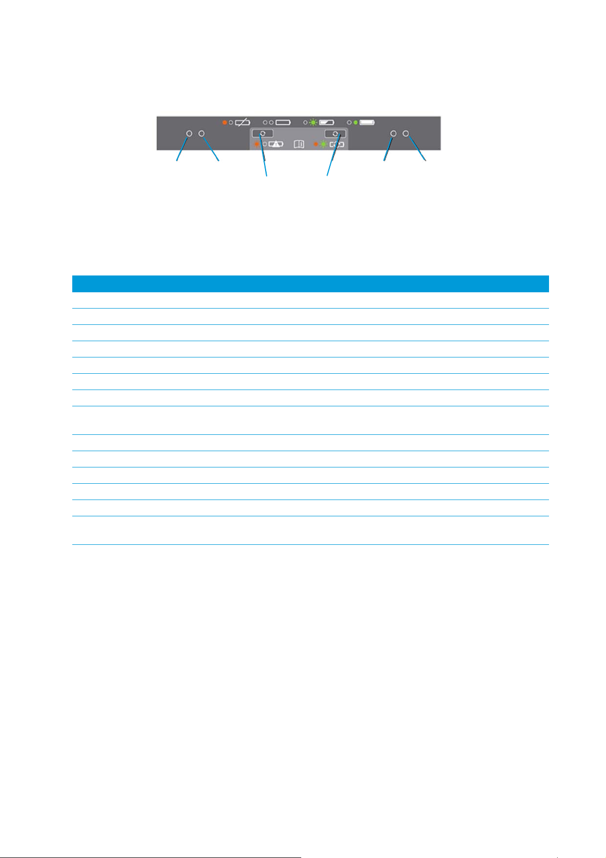
LED Status Indicator
Beside each slot are two LED indicators (Red + Green) to display the battery status.
Trimble S Series Total Station User Guide | 16
Page 17
2 Getting Started
Red LED Red LED Green LEDGreen LED
Conditioning
button
Conditioning
button
Figure 2.6 Dual Slot Charger control panel
Status Red LED Green LED
No battery detected (or battery defective) ON OFF
Battery detected (charging not started)
Conditioning not required OFF OFF
Conditioning required FLASHING OFF
Charging in progress
Conditioning not required OFF FLASHING
Conditioning required FLASHING FLASHING
Over/Under -temperature (Charge is inhibited) One flash every
2.5s
Conditioning in progress ON FLASHING
Conditioning done (battery fully charged) ON ON
Battery fully charged
Conditioning not required OFF ON
Conditioning required FLASHING ON
Power supply over/under -voltage OFF One flash every
FLASHING
2.5s
For more information regarding the Dual Slot Charger, please refer to the documentation delivered with
the charger.
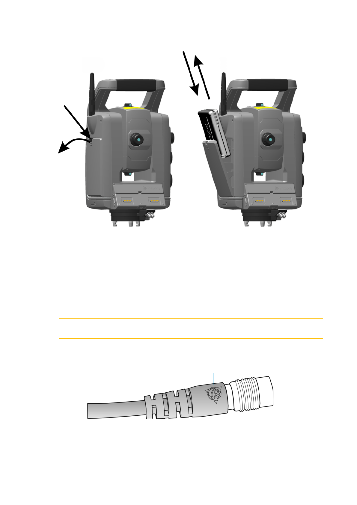
Connecting an Internal Battery
The instrument internal battery fits into the battery compartment on the side of the instrument. This
battery can easily be removed and replaced. To insert the battery:
1. Open the battery compartment hatch by pressing the lock release button.
2. Slide the battery into the battery compartment with the battery connectors positioned towards the
top of the instrument. See Figure 2.7
Trimble S Series Total Station User Guide | 17
Page 18
2 Getting Started
Press
Open
Trimbl e l ogo
Figure 2.7 Inserting and/or removing the internal battery
Connecting an External Battery
The instrument has two external connectors in the base of the instrument. Both connectors can be used
to connect an external power supply to the instrument. External power can be provided by one of the
following:
• Multi Battery Adapter, see Trimble Multi Battery Adapter, page 87
• Car battery, via cable with croc clips or via cable with cigarette lighter connector
CAUTION – Use only the gray cables with 6-pin Hirose connectors from Trimble when connecting
C
a cable to the instrument and Multi Battery Adapter.
TIP – When connecting the cable to the instrument, keep the Trimble logo on the connector
B
upward.
Trimble S Series Total Station User Guide | 18
Page 19
2 Getting Started
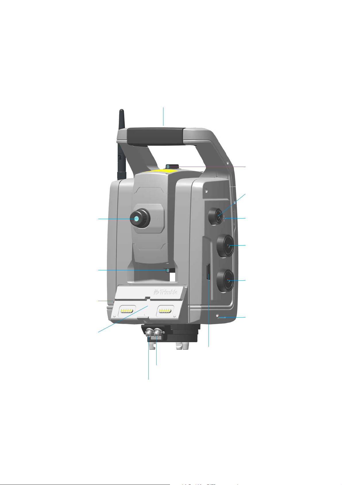
Trimble CU
controller
Foc us ing
servo knob
Vert ical moti on
servo knob
Horizontal motion
servo knob
Communication (COM) connector
Bottom instrument
Coarse sight
Eye-piece
Coarse sight
height mark
Removable
Instr. height mark
Power (+12V) connector
handle
USB
Connector
attachment
On/Off and trigger key
Instrument Description
This section describes the instrument controls. Trimble recommends that you take some time to
familiarize yourself with the names and the locations of the controls. See Figure 2.8 and Fi gure 2. 9
Figure 2.8 Operator’s view of the instrument
Trimble S Series Total Station User Guide | 19
Page 20
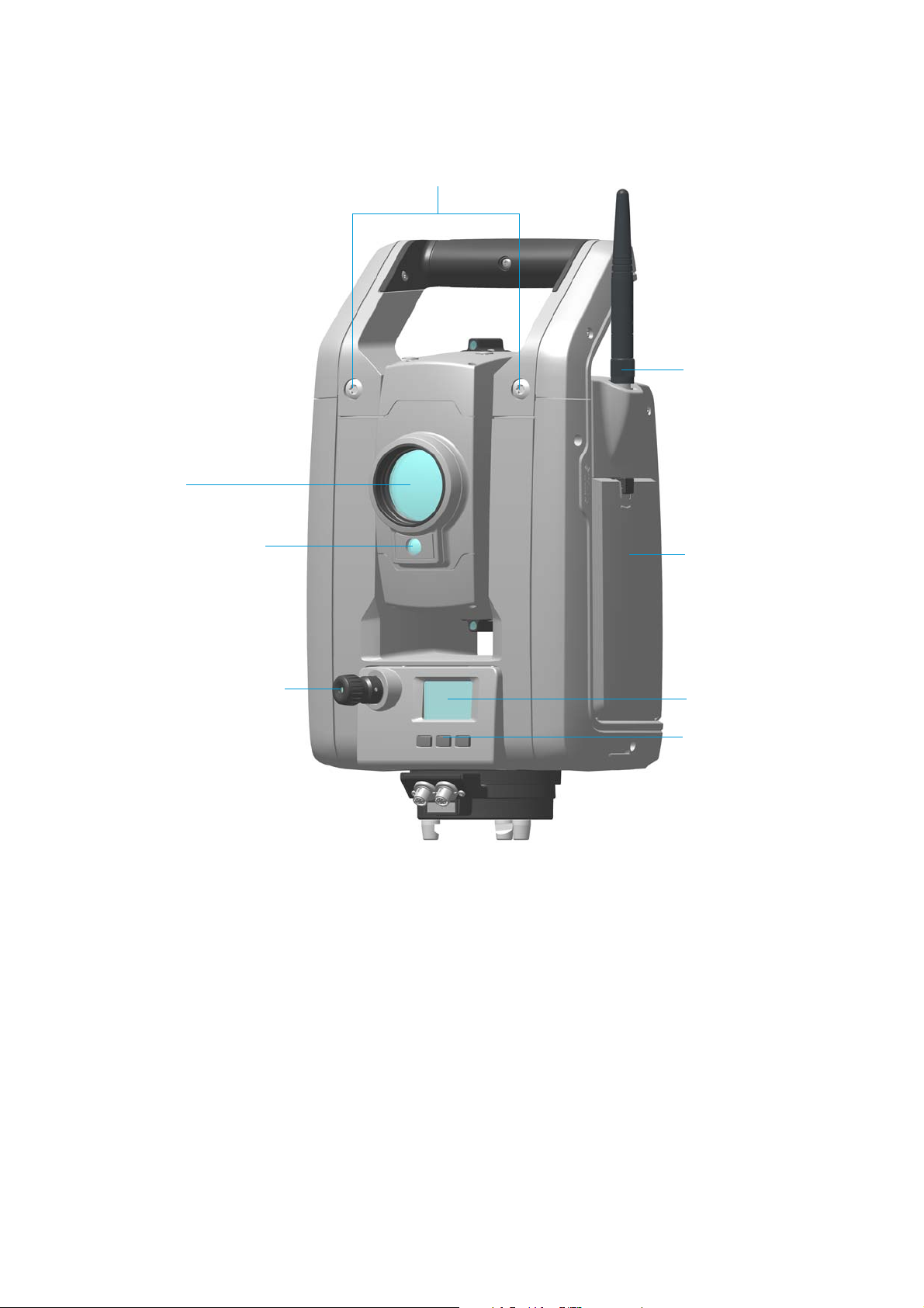
2 Getting Started
Radio antenna
Optical plummet
Fac e 2 display
Fac e 2 keyboard
Compartment for
connector
internal battery
Removable handle screws
Aperture for Tracklight,
Camera or Long Range
Fin eLo ck
Coaxial optics for angle and
distance measurements,
tracker and visible laser
pointer
Figure 2.9 Front view of the instrument
Tr i g g e r Ke y
When there is no Trimble CU attached to the instrument, the trigger key functions as an On/Off key. An
LED in the trigger key indicates if the instrument is turned on. A solid light indicates on and a flashing
light indicates suspend mode.
When there is a Trimble CU running a field application software connected to the instrument, the trigger
key performs the same function as the Enter key on the Trimble CU.
Trimble S Series Total Station User Guide | 20
Page 21
2 Getting Started
Change face
Enter
Scroll
1:250
Setup
Exit
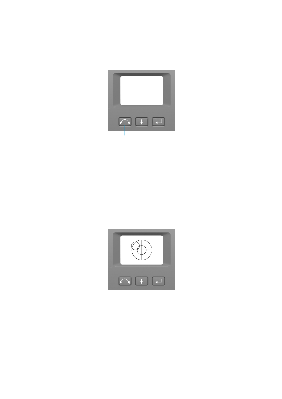
Face 2 Display
The face 2 display is a graphical display with a built-in backlight, and three control buttons. See
Fig ure 2 .10
Figure 2.10 Face 2 display and keyboard
When a secondary function is available on a button, an icon appears at the bottom of the display. To
access the secondary function, press and hold the appropriate key.
When a Trimble CU is attached to the instrument, the software running on the unit controls the face 2
display and keyboard, and determines which secondary functions are available. For details on how the
software controls the face 2 display, refer to the field software documentation.
When there is no Trimble CU attached to the instrument, and you turn on the instrument using the
trigger key, the face 2 display shows an electronic leveling screen. See Fig ure 2 .11
Figure 2.11 Electronic leveling screen on the face 2 display
For information on how to access the compensator menu and instrument setup menu from the face 2
display and keyboard. See Adjusting the Optical Plummet on page 57.
Trimble S Series Total Station User Guide | 21
Page 22
2 Getting Started
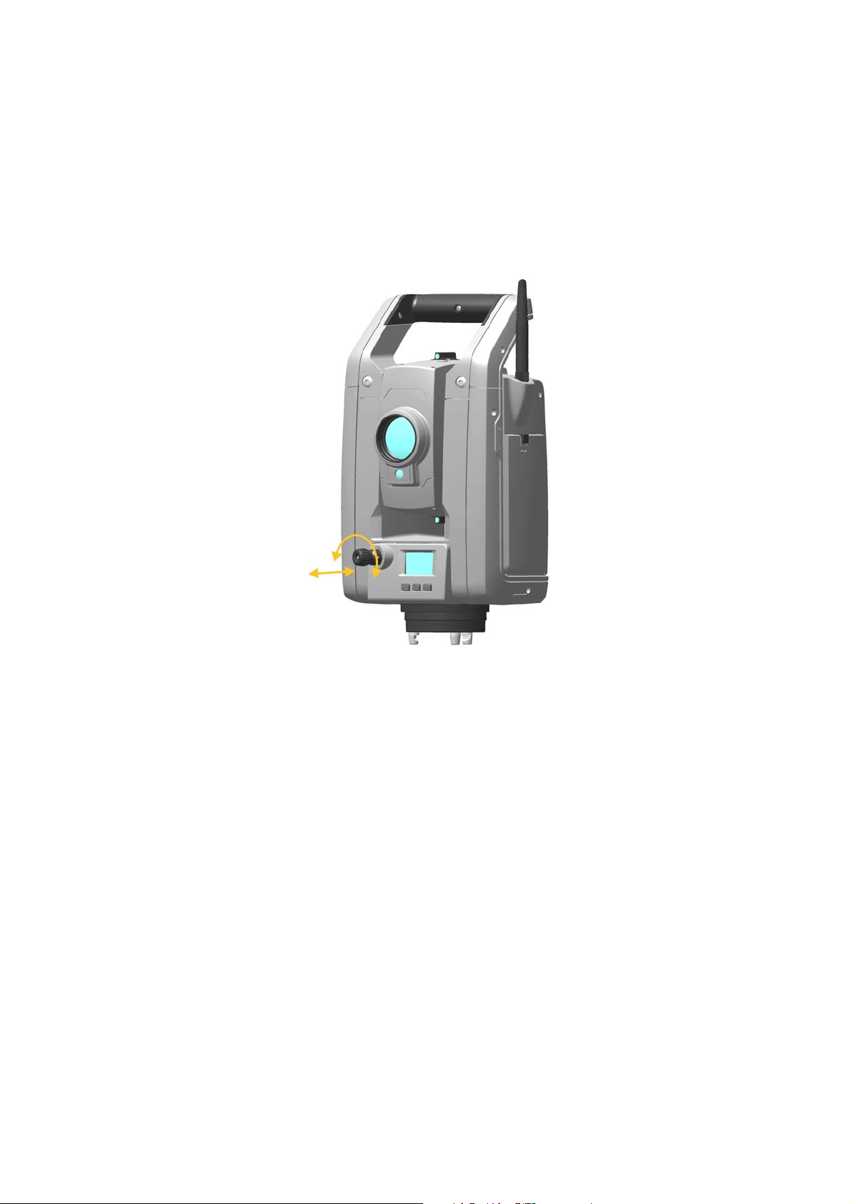
Optical Plummet
The instrument is equipped with an optical plummet, which has 2x magnification and a focusing range
of 0.5 m to infinity. The instrument can be positioned to an accuracy of 0.5 mm at 1.5 m over a ground
mark.
Figure 2.12 Optical plummet
As shown in Fig ure 2 .12:
• To focus the crosshairs, rotate the eye-piece.
• To focus the optical plummet to the ground, push in or pull out the optical plummet.
For information on how to adjust the optical plummet. See Adjusting the Optical Plummet on page 57.
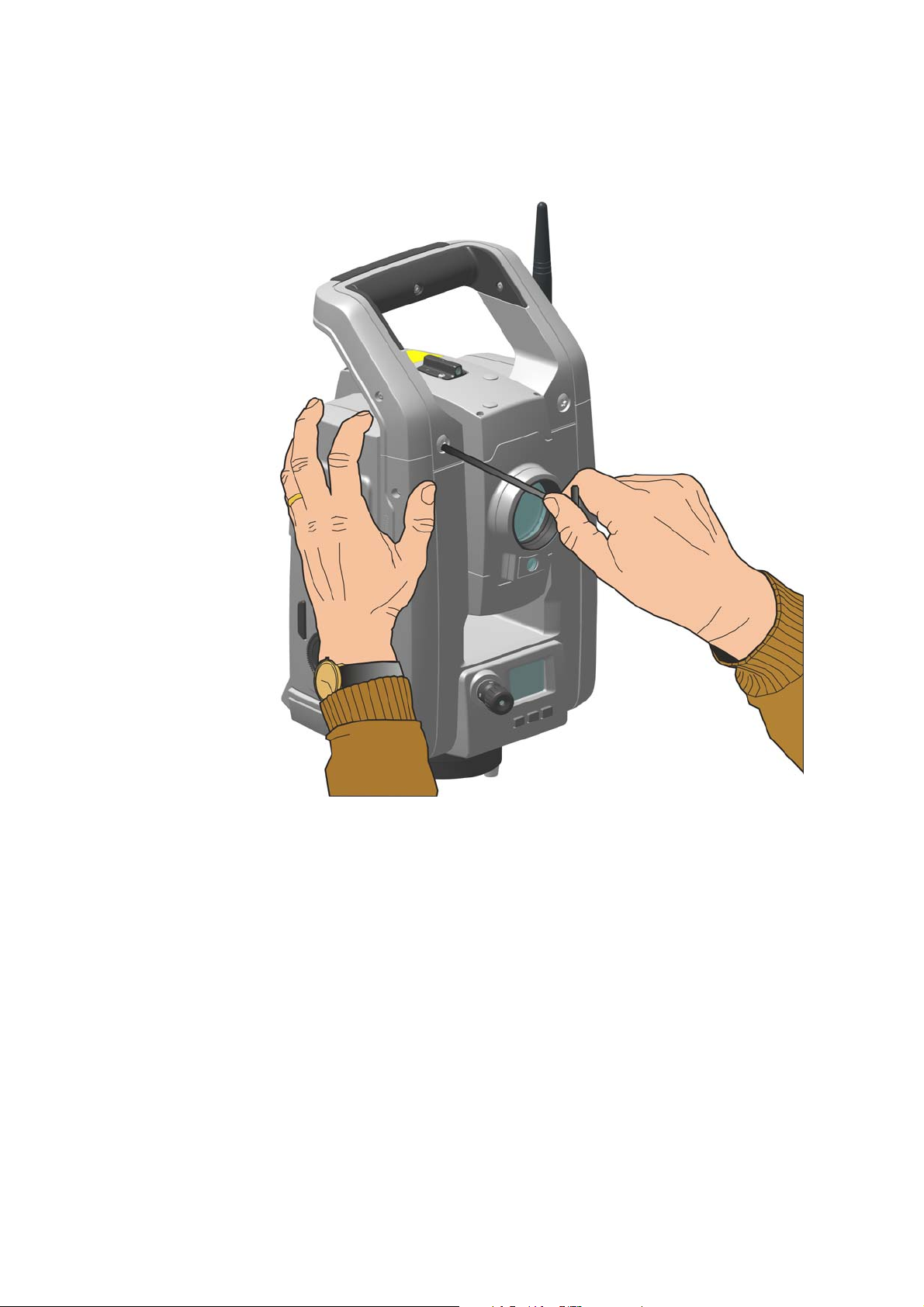
Handle
The handle on the instrument is detachable for measurements in confined spaces, or for instances
where the handle obstructs the sighting line.
The instrument handle is placed so that it will not obscure measurements in the face 1 position, or
restrict plumbing vertically beneath an overhead marker or sighting up a vertical shaft.
The handle can be removed by:
Trimble S Series Total Station User Guide | 22
Page 23
2 Getting Started
1. Unscrew the two Torx screws securing the handle to the instrument, use a T30 Torx key.
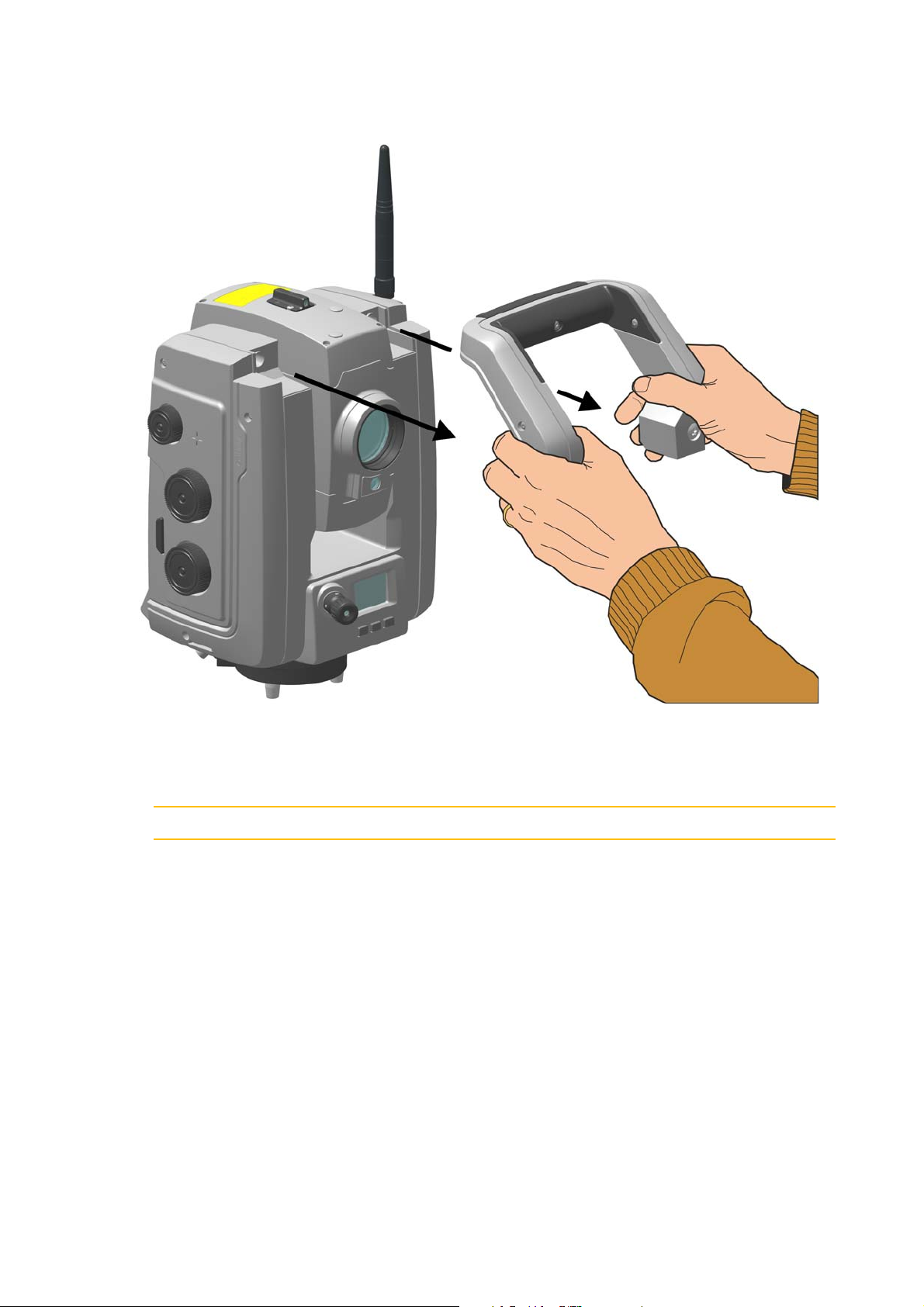
2. Slide the handle horizontally away from the front of the instrument. See Fig ure 2 .13 and Figure 2. 14
Figure 2.13 Removing the instrument handle
Trimble S Series Total Station User Guide | 23
Page 24
2 Getting Started
Figure 2.14 Detaching the instrument handle
Attaching the handle:
Attaching the handle is completed by reversing the above operations.
CAUTION – Make sure that the handle is firmly attached before you lift the instrument.
C
Trimble S Series Total Station User Guide | 24
Page 25

3
Set up
► Setup
► Starting the Instrument
► Leveling
► Instrument Setup
► The Laser Pointer
► Measuring the Instrument Height
► Adjusting the Optical Plummet
3
► Pre Measurement Check List
► Attaching the TCU to the Instrument
► Detaching the TCU
► Trimble TSC3 Controller
Trimble S Series Total Station User Guide | 25
Page 26
3 Set up
Setup
A stable setup is critical for high precision measurements.
Setup Stability
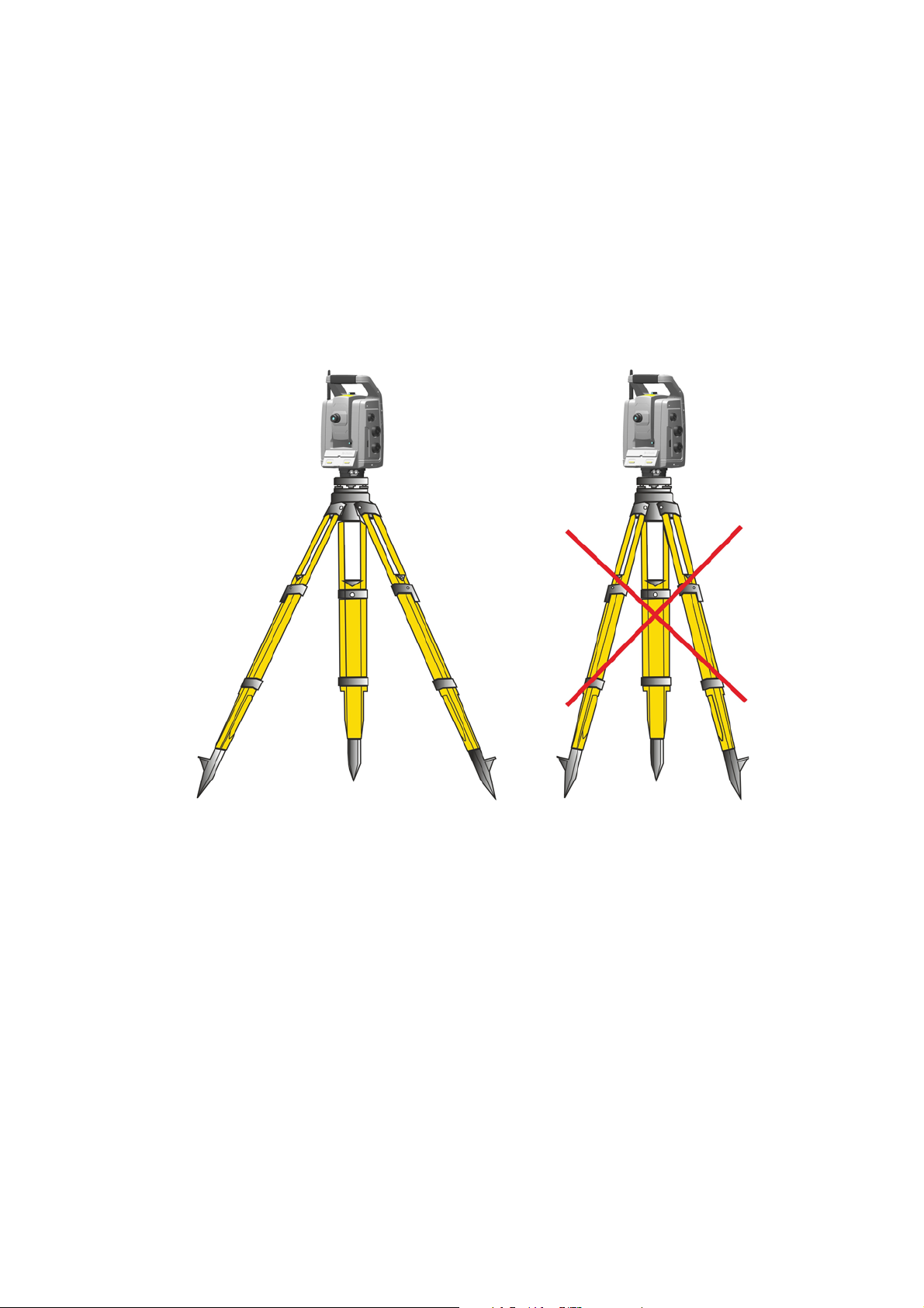
When an instrument is setup it is important to consider the following:
1. Set tripod legs wide apart to increase the stability of the setup. A setup where one leg is placed on e.g
asphalt and the other two on soil will still be a stable setup provided that the tripod legs are set wide
enough. If it is not possible to set the tripod legs wide apart due to obstacles, then the tripod can be
lowered to increase stability.
Figure 3.1 Correct instrument set up
2. Make sure that all the screws on the tripod and/or tribrach are tightened to avoid any play.
3. Any high quality tripod and tribrach can be used. However, Trimble strongly recommends the use of
tripod heads made of steel, aluminum or similar material. Tripod heads of fiberglass or other
composite materials are not recommended.
See Servo Technology on page 80 for more information.
Measurement Stability
Take into account that instruments require sufficient time to adjust to the ambient temperature. The
following rule-of-thumb for a high precision measurement applies: Temperature difference in degree
Celsius (°C) x 2 = duration in minutes required for the instrument to adjust to the new temperature.
Avoid sighting across fields with intense heat shimmer by sun light, e.g. at noon.
Trimble S Series Total Station User Guide | 26
Page 27
3 Set up
-Select Mode-
1:250
Setup
Exit
C
Waiting for
connection...
Ti m e - o u t
in 10 sec.
10
- setup -
>>
C
Channel 8
Network ID 10
>>Setup/Level
Radio settings
Reference HA
Bluetooth settings
Exit (to level)
Security
Starting the Instrument
NOTE – Before following any of the instructions below, put the instrument in the face 2 position, i.e. the
telescope eyepiece and face 2 keyboard and display are pointing towards you.
The face 2 display menus described in this chapter can only be accessed when there is no Trimble CU
attached, please remove the Trimble CU before starting the instrument.
Start the instrument by pressing the trigger key.
Once you start the instrument, the Select Mode menu appears in the face 2 display.
To g o to
Setup/Level
press C.
NOTE – If no selection is made within 10 seconds the instrument will go to suspend mode. To return to
the select mode menu press the trigger key.
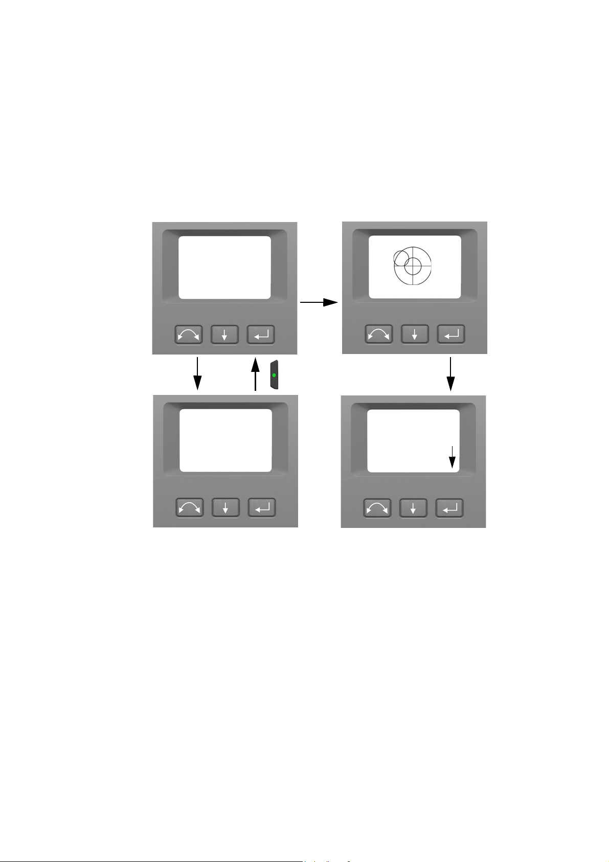
Leveling
Once you have selected Setup/Level, the face 2 display appears with the electronic bubble for leveling. If
there is a Trimble CU attached, the Trimble CU software controls the face 2 display. Fig ure 3.2 shows the
leveling process.
To toggle between a graphical or numerical display make a long press on A.
To change the graphical displays sensitivity (zoom) make a short press on a.
To accept and enter the setup menu press C.
NOTE – Due to the high speed servo it is important to use a high quality tripod and tribrach.
Trimble S Series Total Station User Guide | 27
Page 28
3 Set up
X:0.0054
Y:0 .014 5
C
- Setup -
>>
1:250
Setup
Exit
1:250
Setup
Exit
Radio settings
Reference HA
Bluetooth settings
Exit (to level)
Security
Long
press
A
- Setup -
>>
Radio settings
Reference HA
Bluetooth settings
Exit (to level)
Security
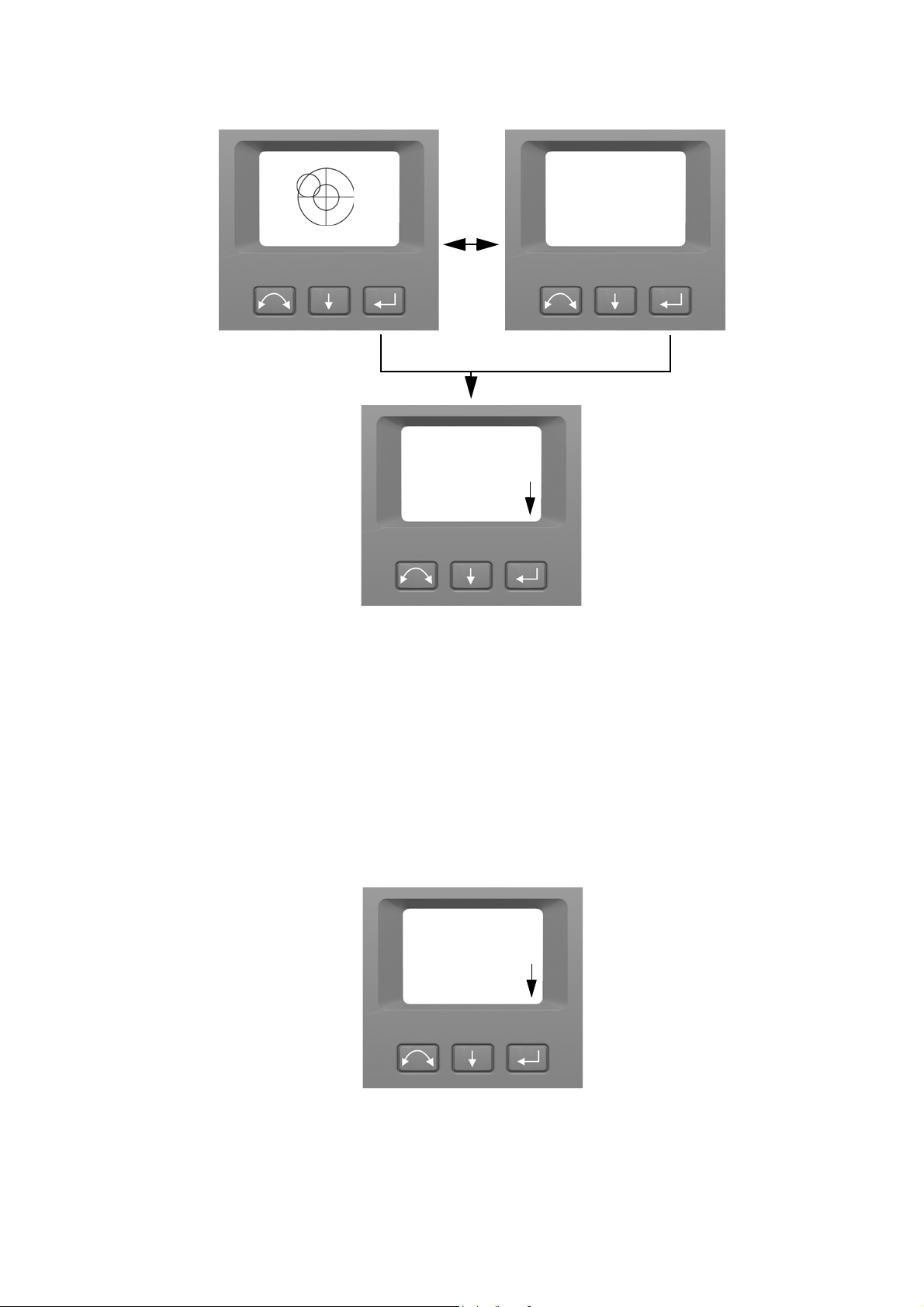
Figure 3.2 The leveling process
NOTE – If the instrument is inactive for longer than 300 seconds (5 minutes) it will go to suspend
mode. See Power Management on page 82
Instrument Setup
With the face 2 display, you can access a number of instrument functions and routines without a Trimble
CU attached:
In the leveling display select
NOTE – It is possible to access the instrument setup menu without leveling the instrument.
Setup
by pressing C, the Setup Menu appears:
Trimble S Series Total Station User Guide | 28
Page 29

The instrument Setup menu is structured as follows:
•Exit (to level)
• Security settings, See Security on page 29
• Radio settings. See page 34.
• Bluetooth
• Reference Horizontal Angle. See page 39.
• Adjustments. See page 39.
–Back
– Compensator calibration. See page 39.
– HA/VA and trunnion axis collimation. See page 41.
– Tracker collimation. See page 45.
– Laser pointer on/off. See page 46.
– Autofocus calibration. See page 47
• Firmware version information. See page 49.
•Service info, See Service Info on page 49
®
settings, See Bluetooth Device Settings on page 37
3 Set up
• Language settings, See Select Language on page 49
Security
To avoid unauthorized use of the instrument a PIN/PUK security code can be activated by the user.
PIN Code
The PIN Code is a four digit code where each digit can be set between 0-9 e.g. “1234”. The PIN Code can
be activated and changed by the user.
As default the PIN Code is set to “0000”. With this code set the security is not activated and the user will
not be prompted to enter PIN Code at start up.
NOTE – If the wrong code is entered more than 10 times, the instrument will be locked and the PUK
Code needs to be entered.
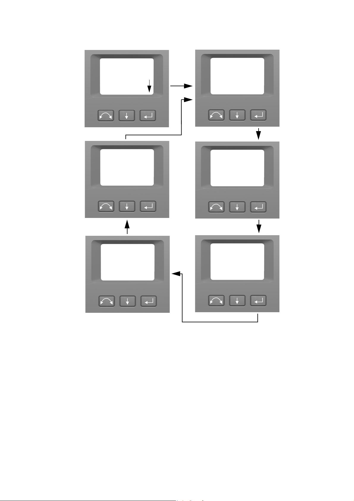
Activate or Change PIN Code
To activate the security PIN Code or change the PIN Code:
1. Press A to scroll to
2. Press A to scroll to
3. Enter the current PIN Code. The underlined digit is selected for change.
a. Press A to change the digit to the correct number.
Security
Change PIN
and then press C.
and then press C.
b. Press b to select the next digit.
c. When all four digits have been set to the correct PIN code press C.
4. Enter the new PIN Code of your choice and press C, follow the instructions 3a, 3b and 3c
5. To confirm the PIN Code press C.
Trimble S Series Total Station User Guide | 29
Page 30
3 Set up
- Setup -
>>
Radio settings
Reference HA
Bluetooth settings
Exit (to level)
Security
- Security -
>>
C
Back....
Change PIN
Get PUK
- Change PIN -
Enter current PIN
0000
Next
Change
Done
- Change PIN -
Enter new PIN
0420
Next
Change
Done
- Change PIN -
Confirm new PIN
0420
Next
Change
Done
- Change PIN -
OK
C
C
C
C
6. Press A to scroll to
Unlock Instrument With PIN Code
When the security PIN Code has been activated, the PIN Code needs to be entered at start up.
To unlock the instrument select
Back....
and then press C to return to the
Unlock Instrument
and press C
Setup
menu.
Trimble S Series Total Station User Guide | 30
Page 31

3 Set up
-Select Mode-
Setup/Level
Done
Next
C
Waiting for
connection...
10
Channel 8
Network ID 10
>>Unlock Instrument
Change
-Enter PIN-
0000
Ti m e - o u t
in 10 sec.
Instrument locked
NOTE – If no selection is made within 10 seconds the instrument will go to suspend mode. To return to
the select mode menu press the trigger key.
The PIN code is a four digit number. The underlined digit is selected for change.
1. Press A to change the digit to the correct number.
2. Press b to select the next digit.
3. When all four digits have been set to the correct PIN code press C.
Trimble S Series Total Station User Guide | 31
Page 32

3 Set up
C
-Enter PIN-
OK
Done
Next
Change
-Enter PIN-
0420
Setup
- setup -
>>
-Select Mode-
Setup/Level
>>Unlock Instrument
Exit
Radio settings
Reference HA
Bluetooth settings
Exit (to level)
Security
If the wrong PIN Code is entered more than ten times, you will be prompted to enter the PUK Code.
When the correct PUK Code has been entered, the PIN Code will be reset to “0000”. This means that the
PIN Code security will be inactivated.
Trimble S Series Total Station User Guide | 32
Page 33

3 Set up
C
-Enter PIN-
Done
Next
Change
-Enter PIN-
1234
Fa il ed
Failed >10 times
- Enter PUK -
0000000000
Done
C
PUK Code
The PUK Code is a ten digit code where each digit is set between 0-9 e.g. “0123456789”. The PUK Code
can not be changed by the user.
The PUK Code is set at the factory. A document with the PUK Code is supplied to the user when the
instrument is delivered. Please save this document in a safe place.
NOTE – If the PUK code has been lost, please contact your authorized Trimble distributor to retrieve the
PUK code.
NOTE – The PUK Code is needed to unlock the instrument if wrong PIN Code has been entered more
than ten times.
You can read out the PUK Code from the instrument:
1. Press A to scroll to
2. Press A to scroll to
3. Press C to return to the
Security
Get PUK
Security
and then press C.
and then press C.
menu.
Trimble S Series Total Station User Guide | 33
Page 34

3 Set up
- Setup -
>>
Radio settings
Reference HA
Bluetooth settings
Exit (to level)
Security
- Security -
>>
C
Back....
Change PIN
Get PUK
- Get PUK -
0123456789
Done
C
C
-Radio settings-
Set radio channel
Set network ID
Back...
>>
C
- Setup -
>>
Radio settings
Reference HA
Bluetooth settings
Exit (to level)
Security
Radio Settings
In the Radio settings menu it is possible to set the radio channel and network ID number.
Set Radio Channel
1. Press A to scroll to
2. Press A to scroll to
3. To change the radio channel number press A to select
Radio settings
Set radio channel
channel number in the display.
and then press C.
and then press C.
Next
and then press C to change the
Trimble S Series Total Station User Guide | 34
Page 35

3 Set up
Set radio channel
Channel: 1
C
next
set
>>
Set radio channel
Channel: 8
next
set
>>
For
example
7
short
presses
Set radio channel
Channel: 8
C
next
set
>>
Storing radio
parameters
-Radio settings-
Set radio channel
Set network ID
Back...
>>
NOTE – a short press on the enter key will increment the radio channel in increments of 1, pressing and
holding the enter key, will increment the radio channel in steps of 10.
Set
4. When you have found the channel number of your choice press A to select
to store this channel number. You will then be returned to the
Radio Settings
and then press C
menu.
5. If you want to cancel Press A to select
menu.
6. To return to the Setup menu Press A to scroll to
Cancel
and then press C to return to the
Back
and then press C.
Trimble S Series Total Station User Guide | 35
Radio Settings
Page 36

Set Network ID
C
-Radio settings-
Set radio channel
Set network ID
Back...
>>
- Setup -
>>
Radio settings
Reference HA
Bluetooth settings
Exit (to level)
Security
Set network ID
Network ID: 100
C
next
set
>>
Set network ID
next
set
>>
For
example
1
5
short press
long press
and
Network ID: 100
1. Press A to scroll to
Radio settings
3 Set up
and then press C.
2. Press A to scroll to
3. To change the network ID number press A to select
number in the display.
NOTE – a short press on the enter key will increment the network ID in increments of 1, pressing and
holding the enter key, will increment the network ID in steps of 10.
Network ID range 0-255
Set network ID
and then press C.
Next
and then press C to change the channel
4. When you have found the network ID number of your choice press A to select
C to store this network ID number. You will then be returned to the
Trimble S Series Total Station User Guide | 36
Radio Settings
Set
and then press
menu.
Page 37

3 Set up
Set network ID
Network ID: 115
C
next
set
>>
Storing radio
parameters
-Radio settings-
Set radio channel
Set network ID
Back...
>>
5. If you want to cancel Press A to select
6. To return to the Setup menu Press A to scroll to
Bluetooth Device Settings
The instrument are equipped with Bluetooth® wireless technology for cable free operations. The
Bluetooth device antenna is located directly beneath the controller attachment plate in the face 1
position. In order to facilitate communications between a TSC3 controller or Tablet computer and the
instrument, first enable the Bluetooth wireless technology option in the instrument. This is carried out
as follows.
C
Cancel
menu.
and then press C to return to the
Back
and then press C.
Radio Settings
CAUTION – Before starting the Bluetooth device, make sure that the regulations of the country
that you are working in allows the use of Bluetooth wireless technology.
Trimble S Series Total Station User Guide | 37
Page 38

3 Set up
- Setup -
>>
C
Bluetooth dev. is off
Set mode: off
next
set
>>
Radio settings
Reference HA
Bluetooth settings
Exit (to level)
Security
C
Bluetooth dev. is on
Set mode: on
next
set
>>
Bluetooth dev. is off
Set mode: off
next
set
>>
C
Bluetooth dev. is on
Set mode: on
next
set
>>
- Setup -
>>
Radio settings
Reference HA
Bluetooth settings
Exit (to level)
Security
1. Press A to scroll to
2. To change the Bluetooth device setting press A to select
Bluetooth settings
then press C.
Next
and then press C to select on or
off
3. When you have found the setting of your choice press A to select
this setting. You will then be returned to the
4. If you want to cancel Press A to select
NOTE – At delivery the Bluetooth device is by default in off mode. Any change to this setting made by
an operator will become the default setting until changed again.
NOTE – To reduce power consumption and extend operation time, Trimble recommends that the
Bluetooth device is switched off when not in use.
setup
menu.
Cancel
and then press C to return to the
Set
and then press C to store
setup
menu.
Trimble S Series Total Station User Guide | 38
Page 39

Reference HA
Aim at target
C
Cancel
OK
- Setup -
>>
Radio settings
Reference HA
Bluetooth settings
Exit (to level)
Security
-Adjustments-
Tracker collim.
HA/VA collimation
Compensator calib.
Laser pointer
Back...
>>
C
- Setup -
>>
Radio settings
Reference HA
Bluetooth settings
Adjustments
Security
3 Set up
1. Press A to scroll to
2. Aim the instrument in face 2 towards the target and then press enter C to set or b to cancel.
Since the instrument is aimed at the reference target in face 2 while setting the reference HA, the
instruments horizontal circle will be set to 180 degrees or 200 grads. This makes the reference HA 0
degrees or grads in face 1.
The Setup menu appears.
Reference HA
and then press C.
Adjustments Menu
The adjustments menu contains all the instrument collimation and calibration routines.
•Press A to scroll to
Adjustments
and then press C.
Compensator Calibration
To calibrate the compensator, the instrument needs to be in perfect balance. After calibration the
compensator sensor will automatically adjust and allow for changes in that balance caused by the
presence of a Trimble CU controller or the absence of an internal battery.
To minimize imbalance in the instrument:
• Do not have the Trimble CU mounted on the instrument.
• An internal battery must be present in the battery compartment.
• The instrument handle must be attached.
• The instrument will automatically position the telescope and distance unit for best balance.
Trimble S Series Total Station User Guide | 39
Page 40

3 Set up
To start the compensator calibration:
1. Level the instrument. The instrument will automatically check if the compensator is within range
before the calibration is started.
2. Press A to scroll to
Compensator calib.
and then press C.
3. Follow the instructions in the display. Figu re 3.3.
NOTE – Trimble recommends that you regularly carry out a compensator calibration, particularly when
measuring during high temperature variations and where the highest measurement accuracy is
required.
The calibration process involves the instrument automatically reading the compensator value at a
series of predetermined positions through the full rotation of the instrument. The process takes
approximately one minute to complete. During the process the instrument should be on a stable
platform, free from vibration and untouched by the user.
Trimble S Series Total Station User Guide | 40
Page 41

3 Set up
Ensure instrument
handle is installed.
Ensure control unit is
not installed.
Balancing...Compensating...
Compensation
complete!
C
C
C
-Adjustments-
Tracker collim.
HA/VA collimation
Compensator calib.
Laser pointer
Back...
>>
Next
Next
Figure 3.3 Compensator calibration routine
HA/VA Collimation and Trunnion Axis Tilt
The instrument utilizes precise angle and distance measurements to determine the position of the point
being measured. The instruments design facilitates the ability to measure all points with a single
pointing to the target in the face 1 position. All electronic total stations are subject to collimation errors
in both the horizontal and vertical angle measuring systems, and also errors caused by the axis of the
telescope not being truly perpendicular to the vertical of the instrument.
In order to compensate for these errors, the collimation routine allows the operator to accurately
determine the current errors in the instrument, and store the errors as corrections to be applied to all
measurements made in a single pointing to a target. In this way the instrument will always provide
accurate measurements:
Trimble S Series Total Station User Guide | 41
Page 42

3 Set up
HA: 0.0010
VA: 0.0012
Cancel
-Current values-
Continue
>>
C
-Adjustments-
Tracker collim.
HA/VA collimation
Compensator calib.
Laser pointer
Back...
>>
The Collimation errors and Trunnion axis tilt will change over time, the most common changes being
caused by
• Wear and tear with use
• Bumps and knocks during transit
• Large changes in operating temperature
Trimble recommends that a collimation check and tilt axis check be carried out routinely as follows:
• After any long uncontrolled transport of the instrument (e.g. after service or shipment to a new
location)
• After any accidental knock or drop
• At any time when the operating temperature changes by more than 10°C (18°F)
• At any time when the instrument changes it's height above sea level by more than 500m (1640 Feet)
• At any time when the highest accuracy positions are required
• Routinely on a periodic basis (Monthly, weekly etc.)
Trimble also recommends that the operator keep a record of the dates and values measured so that any
gross changes can easily be detected. Gross changes can indicate the need for a check by an approved
service center.
The adjustment of the instrument for HA/VA collimation and Trunnion Axis tilt is a two stage process.
The Horizontal and Vertical collimation and the trunnion axis tilt correction have been measured and
stored in the instrument at the factory.
In all calibrations, multiple sightings will be made in both faces to ensure that any minor pointing errors
can be eliminated in the accurate determination of current collimation error values.
In a new instrument the values should be close to zero, over time these will change. The instrument
allows a maximum value of 0.05 grads (0.045 degrees) in the HA, VA and Trunnion axis tilt values. If
these values are exceeded, the instrument will need service to rectify a mechanical problem.
1. Press A to scroll to
2. Press A to scroll to one of the following:
HA/VA collimation
The current collimation values appear.
–
–
Continue
Cancel
Then press C to continue the HA/VA collimation test.
. Then press C to return to the
and then press C.
Adjustments
menu.
Trimble S Series Total Station User Guide | 42
Page 43

If you select Continue:
Aim on target
New observation
Change face
>>
Fac e-1 obs : 0
New observation
Change face
Fac e-2 obs: 0
>>
C
3. Press A to scroll to one of the following:
–
New observation.
–
Change face
–
Cancel
. Then press C to return to the
If you select New observation:
Then press C to continue the HA/VA collimation test.
. Then press C to change between face 1 and 2.
Adjustments
3 Set up
menu.
a. Aim accurately in face 2 towards a point near the horizon at max. ±5 grads (± 4.5 degrees) to the
horizontal and at a minimum distance of 100 m (328 ft.).
b. Press A to scroll to
c. Re sight the instrument at the same point and press the enter key again. Repeat this process for a
minimum of 5 sightings in face 2.
d. Press A to scroll to
e. Aim accurately towards the same point as that used in face 2.
f. Press A to scroll to
g. Re sight the instrument at the same point and press the enter key again. Repeat this process for
the same number of times as in face 2.
As observations are made on the first face (either face 1 or face 2), the angle values are stored and
the counter increases. When one or more observations have been taken on each face, and the
number of observations on each face are the same, the software calculates and displays the new
horizontal and vertical collimation values.
4. Press A to scroll to one of the following:
–
Trunnion coll
–
Store correction
–
Cancel
. Then press C to continue to Trunnion collimation.
. Then press C to accept and store the new collimation values.
. Then press C to return to the
New observation
Change face
New observation
. Then press C to change to face 1.
. Then Press C to measure and record angles
. Then Press C to measure and record angles
adjustments
menu.
Trimble S Series Total Station User Guide | 43
Page 44

3 Set up
Fac e-1 obs: 5
New observation
Change face
Fac e-2 obs: 5
>>
HA: 0.0010
VA: 0.0 012
-Current values-
Trunnion coll.
>>
Store correction
Aim on target
New observation
Change face
>>
HA: 0.0010
VA: 0.0012
-Current values-
Trunnion coll.
>>
Store correction
C
Face-1 obs: 0
New observation
Change face
Face-2 obs: 0
>>
Face-1 obs: 5
New observation
Change face
Face-2 obs: 5
>>
C
Select
5. Press A to scroll to
Trunnion coll.
to continue with trunnion axis tilt collimation.
Trunnion coll.
Then press C to continue the Trunnion axis tilt test.
6. Press A to scroll to one of the following:
–
New observation
–
Change face
–
Cancel
. Then press C to return to the adjustments menu.
If you select
a. Aim accurately in face 2 towards a point at least 15 grads (13.5 degrees) above or below the point
where the collimation test was made at a minimum distance of 30 m (66 ft.).
b. Press C to measure and record angles.
. Then press C to continue the trunnion axis tilt test.
. Then press C to change face.
New observation
the number of observations in both faces appears:
Trimble S Series Total Station User Guide | 44
Page 45

3 Set up
Trunnion: 0.0003
Cancel
-Current values-
>>
Store correction
C
-Adjustments-
Tracker collim.
HA/VA collimation
Compensator calib.
Laser pointer
Back...
>>
c. Press A to scroll to
d. Aim accurately towards the point.
e. Press C to measure and record angles.
As observations are made on the first face (either face 1 or face 2), the angle values are stored and
the observation counter increases. When one or more observations has been taken on each face,
and the number of observations on each face are the same, the software calculates and displays the
new trunnion axis tilt value.
7. P r e s s A to scroll to one of the following:
–
Store correction
appears.
. Then press C to accept the new trunnion axis tilt value. The
Change face
. Then press C to change face.
Adjustments
menu
–
Cancel
. Then press C to return to the
NOTE – The instrument will prohibit a trunnion axis tilt test if it is made towards a point with an angle
less than 15 grads (13.5 degrees) from the point where the collimation test was made. The trunnion axis
tilt determination accuracy will improve with a steeper angle towards the measured point. The minimum
distance for the trunnion axis tilt measurement is 30 m (66 ft.).
NOTE – If the trunnion axis tilt correction value is greater than 0.05 grads (0.045 degrees), the
message
greater than 0.05 grads (0.045 degrees) and you answer No to the re measurement message, the
instrument uses the correction value previously stored in the instrument. If the value is greater than
0.05grads (0.045 degrees), then the instrument must be mechanically adjusted at the nearest
authorized Trimble service center.
Fail Remeasure?
appears. Press Yes and then repeat the measurement procedure. If the value is
Adjustments
menu.
Autolock Collimation
The instrument tracker unit is designed to be coaxial with the instrument cross hairs. If for any reason
the alignment of the tracker deviates from the line of the telescope cross hairs, then errors in position of
the point being measured would result. For this reason an Autolock collimation check needs to be
carried out on a regular basis (under the same conditions as the HA/VA collimation check) to ensure
that any slight misalignment is corrected for.
Perform the test over a similar distance as that you will be working on, but at least 100 m. The prism
target must be very still during the test (Trimble recommends that you use a tripod or bi-pod mount for
the target) and must be in clear line of sight without any obstructing traffic. The instrument is calibrated
to accurately point at the center of the target in both horizontal and vertical axes. The calibration is used
to correct the positions of all points measured using the Autolock function. The measured calibration
values are stored and used until a new set of calibration values are determined.
Trimble S Series Total Station User Guide | 45
Page 46

3 Set up
HA: 0.0010
VA: 0.0 012
Cancel
-Current values-
>>
Continue
C
-Adjustments-
Tracker collim.
HA/VA collimation
Compensator calib.
Laser pointer
Back...
>>
Aim at target
New observation
Change face
>>
HA: 0.0010
VA: 0.0012
Cancel
-Current values-
>>
Store correction
C
NOTE – The adjustment between the two optical axes, i.e. the Telescope and the Tracker, may differ.
See Aiming on page 77
1. Press A to scroll to
2. Accurately aim towards a prism.
3. Press A to scroll to
Tracker collim
New observation
then press C.
and then press C.
4. The instrument will measure to the target in both faces automatically and then display the current
5. Press A to scroll to one of the following:
6. Once the instrument has stored the correction values, the
Laser Pointer
The laser pointer is a visible laser that is emitted from the telescope along the line of sight. The laser is
used to visibly indicate the point being measured, and is especially useful when employing the DR
reflectorless EDM for measurement. The laser pointer is clearly visible in areas of shadow, inside
buildings and tunnels and also at night, however in bright sunshine it is generally not readily visible with
the human eye.
The following controls allow the laser pointer to be switched On and Off.
NOTE – The laser pointer is mechanically aligned to the telescope cross hairs. The laser may require
periodic adjustment to keep it perfectly aligned for measurement. In order to adjust the laser pointer it
has to be switched On, see page 3-50
values.
–
Store correction
–
Cancel
. Then press C to save the correction values.
. Then press C to return to the
Adjustments
menu
Adjustments
Trimble S Series Total Station User Guide | 46
menu appears.
Page 47

3 Set up
Set laser pointer
Set mode: Off
C
-Adjustments-
Tracker collim.
HA/VA collimation
Compensator calib.
Laser pointer
Back...
>>
Next
Set
>>
C
Set laser pointer
Set mode: On
Next
Set
>>
Set laser pointer
Set mode: Off
Next
Set
>>
C
Set laser pointer
Set mode: Off
Next
Set
>>
-Adjustments-
Tracker collim.
HA/VA collimation
Compensator calib.
Laser pointer
Back...
>>
1. Press A to scroll to
2. To change the laser pointer setting press A to select
Laser pointer
then press C.
Next
and then press C to select On or
Off
3. When you have found the setting of your choice press A to select
4. If you want to cancel Press A to select
Autofocus calibration
The instrument is equipped with an autofocus function. Before you can start using the autofocus, the
function needs to be calibrated.
To start the calibration
Set
and then press C to store
this setting. You will then be returned to the
With the laser pointer on, you can adjust the beam, For more information, see The Laser Pointer,
page 50.
Adjustments
Cancel
and then press C to return to the
menu.
Adjustments
menu.
Trimble S Series Total Station User Guide | 47
Page 48

3 Set up
-Adjustments-
Compensator calib.
HA/VA collimation
Tracker collim.
Laser pointer
Autofocus calib
>>
Aim at Prism and
focus manually
(Dist > 500m)
c
Calibrating
Calibration completed
successfully
- Setup-
>>
C
-Adjustments-
Tracker collim.
HA/VA collimation
Compensator calib.
Laser pointer
Back...
>>
Radio settings
Reference HA
Bluetooth device
Adjustments...
Firmware version
1. Remove the CU from the instrument
2. Level the instrument. The instrument will automatically check if the compensator is within range
before the calibration is started.
3. Press a to scroll to
4. Aim and manually focus at a target at a distance of at least 500 meters Then press c.
Autofocus calib
and press c
Back
1. To return to the
Setup
menu, press A to scroll to
Back...
and then press C.
Tr i mb le S S er ie s Tot al S t at i o n Us er G u ide | 48
Page 49

Firmware Version Information
version: RX.X.X
C
- Setup -
>>
Radio settings
Reference HA
Bluetooth device
Adjustments...
Firmware version
Next service date
C
- Setup -
>>
Reference HA
Bluetooth device
Adjustments...
Firmware version
Service info
2016-03-25
or
in242 Hours
3 Set up
1. Press A to scroll to
on the screen. The program will return automatically to the
Firmware version
and then press C. The instrument firmware version appears
Setup
menu.
Service Info
In the
Service info
many run time hours the instrument have left before service is recommended.
1. Press A to scroll to
screen. The program will return automatically to the
menu it is possible to see the date for the next recommended service occasion or how
Service info
and then press C. The instrument service info appears on the
Setup
menu.
Select Language
In the
1. Press A to scroll to
2. Press A to scroll through the available languages.
3. Press C to set language.
Select language
it is possible to select the language for the Face 2 display.
Select language
and then press C.
Tr i mb le S S er ie s Tot al S t at i o n Us er G u ide | 49
Page 50

Exit Menu
- Setup -
>>
Reference HA
Adjustments
Fir mware version
Select language
C
- Language Menu -
Language: ENG
cancel next set
Service info
C
- Setup -
>>
1:250
Setup
Exit
Radio settings
Reference HA
Bluetooth settings
Exit (to level)
Security
3 Set up
1. To exit the
appears.
NOTE – If the instrument is left idle for more than 300 seconds (5 minutes) during any of the above
routines, then the instrument goes to suspend mode.
Setup
menu press A to scroll to
Exit (to level)
and then press C. The electronic level
The Laser Pointer
The S9 HP Total Station uses a red laser beam to measure and as a laser pointer. The Trimble S5, S7, and
S9 Total Stations uses a red laser only as a laser pointer. The laser pointer is coaxial with the line of sight
of the telescope. If the instrument is well adjusted, the red laser pointer coincides with the line of sight.
External influences such as shock or large temperature fluctuations can displace the red laser pointer
relative to the line of sight.
The Trimble S9 High Precision can be equipped with an optional Class 3R High Power Laser Pointer. This
laser pointer is not coaxial with the telescope’s line of sight. For it’s location, see Figure 2.9
Aligning the Laser Pointer
C
CAUTION – Viewing the laser spot on the adjustment target through the telescope is safe. Do not
try to make the adjustment using a prism, the reflected light from a prism can be dazing.
Trimble S Series Total Station User Guide | 50
Page 51

3 Set up
CAUTION – Do not use the laser pointer as an aid when searching for prisms, the reflected light
C
can daze your eyes. The reflected light will not damage your eyes, but might be uncomfortable.
To avoid faulty measurements when using the laser pointer for aiming, use the supplied adjustment
target to check the laser alignment regularly and before you attempt precise distance measurements:
1. Setup the adjustment target 25–50 meter away, facing the instrument.
2. Aim the instrument to the center of the target plate and then inspect the position of the red laser
spot in relation to the telescope cross-hairs.
3. If the red laser spot lies outside the cross-hairs, adjust the direction of the beam until it matches the
cross-hairs, see Figure 3.4 or see Figure 3.5
Figure 3.4 Adjustment target for Trimble S5, S7,and S9 Total Station.
Figure 3.5 Adjustment target with reflective foil for Trimble S9 HP Total Station.
Trimble S Series Total Station User Guide | 51
Page 52

Adjusting the Laser Pointer
Access hole
for horizontal
adjustment
Access hole
for vertical
adjustment
1. Pull out the two plugs from the adjustment screw access holes on top of the telescope housing.
Fig ure 3.6
3 Set up
Figure 3.6 Access holes for the Laser pointer adjustment screws
2. To correct the vertical position of the laser spot, insert the Allen key into the access hole for the
vertical adjustment screw and turn it as shown in figure 3.7.
Trimble S Series Total Station User Guide | 52
Page 53

3 Set up
Clockwise = Down
Counter clockwise = Up
Figure 3.7 Laser pointer vertical position adjustment
3. To correct the horizontal position of the laser spot, insert the Allen key into the horizontal adjustment
port and turn it as shown in Figure 3.8.
Trimble S Series Total Station User Guide | 53
Page 54

3 Set up
Clockwise = Left
Counter Clockwise = Right
Figure 3.8 Laser pointer Horizontal position adjustment
4. Check the alignment of the laser spot and the cross-hairs. Throughout the adjustment procedure,
keep the telescope pointing to the adjustment target. The adjusting screws are of a high tension
because they are self locking. The screws tighten automatically after you adjust them.
5. Refit the plugs in the adjustment holes. Make sure that the plugs are correctly fitted for proper
sealing against the cover.
C
CAUTION – To keep out moisture and dust, make sure that the plugs are correctly fitted in the
adjustment ports.
Trimble S Series Total Station User Guide | 54
Page 55

3 Set up
Top ma rk
Bottom mark
Top ri dg e of
bottom mark
Measuring the Instrument Height
There are two measurement marks on the side of the instrument. The top mark corresponds to the
trunnion axis of the instrument. The bottom mark is 0.158 m (0.518 ft.) below the top mark. Measure
the bottom mark to the top ridge of the mark. Figure 3. 9
Figure 3.9 Instrument height marks
When there is a Trimble CU or TSC3 attached running a field application software, the software has
additional functions that reduce the bottom mark measurement to the required vertical instrument
height to the trunnion axis, see Figure 3.10 and the following paragraph.
Trimble S Series Total Station User Guide | 55
Page 56

3 Set up
0.158m
Hm Hc Ih
(0.518ft)
Ih 0 158 Hm20 091
2
–+=
Figure 3.10 Instrument height measurement
The measured distance (Hm) is corrected for the slope of the measurement to obtain a vertical
measurement to the bottom mark (Hc). The constant from the bottom mark to the top mark
(0.158 m/0.518 ft.) is added to the Hc to obtain the vertical instrument height from the ground mark to
the trunnion axis (Ih). For more information, refer to the field software documentation.
Alternatively, to obtain an accurate measurement to the top mark (Ih), you can manually measure the
slope distance from the ground to the bottom mark (Hm). To calculate the total instrument height (Ih),
insert the measured slope distance (Hm) into the formula below:
Trimble S Series Total Station User Guide | 56
Page 57

3 Set up
Adjusting the Optical Plummet
1. Set up the instrument and level it over a ground mark so that the tripod height is 1.5 m (±0.1 m)
(4.920 ft. (±0.328 ft.)). Fig ure 3.1 1
2. Note the position of the inner circle of the optical plummet in relation to the ground mark.
3. Turn the instrument 200 grads (180 degrees).
4. Note the position of the inner circle of the optical plummet in relation to the ground mark. If the inner
circle of the optical plummet reticule moves in relation to the ground mark, you must adjust the
plummet reticule location.
5. Adjust out half of the error with the four adjustments screws on the optical plummet.
6. Turn the instrument 200 grads (180 degrees).
7. If there is no movement between the inner circle of the optical plummet reticle in relation to the
ground mark, no further adjustment is needed.
CAUTION – When adjusting the optical plummet with the four adjustment screws it is important
C
that the screws are correctly adjusted. When one screw is adjusted the opposite screw must be
adjusted equally in the reverse direction, in order to keep the correct tension on the optics. Do not
over tighten the screws, this might damage the optics.
Trimble S Series Total Station User Guide | 57
Page 58

3 Set up
Optical plummet
Ground mark
reticule 4x Adjustment screws
Figure 3.11 Optical plummet adjustment
Pre Measurement Check List
Before you begin measurement or stake out operations, check the following items:
• Lenses are clean
• Instrument is correctly leveled
• Collimation error
• Tracker collimation error (if the instrument is equipped with Autolock capability)
• Trunnion axis tilt
• Correct radio channel is selected (robotic measurements only)
Trimble S Series Total Station User Guide | 58
Page 59

3 Set up
• Laser Pointer beam alignment
• Measure instrument height
• Allow sufficient time for the instrument to adjust to the ambient temperature, see page 26
Connecting a Controller
To perform surveying with the instrument a controller must be connected to the instrument running a
field software.
Trimble CU Controller
The Trimble CU controller (TCU) can be used as a controller for the instrument.
The TCU can use different methods to communicate with the instrument:
• Attached to the attachment on the instrument (A).
• Bluetooth wireless technology, when attached to Robotic Holder or Docking Station (B).
• Radio, with robotic instruments when attached to Robotic holder (C).
Figure 3.12 Connecting the TCU to the instrument
Trimble S Series Total Station User Guide | 59
Page 60

Attaching the TCU to the Instrument
1. Hook the top of the TCU over the top edge of the panel attachment, Figure 3.13
3 Set up
Figure 3.13 Attaching the TCU to the instrument
2. Push the bottom of the TCU toward the panel attachment until it clicks into place, Figure 3.14
Trimble S Series Total Station User Guide | 60
Page 61

3 Set up
(((Click)))
Figure 3.14 Attaching the TCU
Detaching the TCU
CAUTION – When the TCU is removed from the instrument it is recommended to have the TCU in
C
suspend or off mode.
To remove the Trimble CU from the instrument when in on mode will not damage the equipment,
but files that are being saved or written to when the TCU is being removed might be damaged or
lost.
1. Push the lock release button on the bottom of the TCU, Figure 3.15 (1)
2. Lift the bottom of the TCU away from the instrument, Figure 3.15 (2)
Trimble S Series Total Station User Guide | 61
Page 62

3 Set up
Push to unlock
Figure 3.15 Detaching the TCU
3. Unhook the top of the TCU from the top edge of the panel attachment and remove the TCU from the
instrument, Fig ure 3.16
Trimble S Series Total Station User Guide | 62
Page 63

3 Set up
Figure 3.16 Detaching the TCU
NOTE – When a Trimble CU Controller is not attached to the instrument the Panel Attachment Cover
P/N 50014012 should be attached for full ESD protection and to protect the connectors from
mechanical damage and corrosion. See ESD Information on page 4
Connecting With Bluetooth Wireless Technology
CAUTION – Before activating the Bluetooth device, make sure that the local regulations allows
C
the use of Bluetooth wireless technology.
The TCU has integrated Bluetooth wireless technology. Refer to the field software documentation
regarding how to activate and set up the TCU Bluetooth device.
The TCU must be attached to a Robotic Holder for power supply. To set up the Robotic Holder, See
Trimble Robotic Holder on page 95
Connecting with Radio
A robotic instrument is equipped with a radio that can communicate with the TCU through the radio in a
Robotic Holder. The TCU must be attached to a Robotic holder for power supply and connection to a
radio.
Trimble S Series Total Station User Guide | 63
Page 64

3 Set up
USB Port
The two radios must be set to the same channel to be able to establish communication. The radio
channel for the instrument radio can be set in the following ways:
•In the face 2 panel, see page 3-34
• In the TCU field software when the TCU is attached to the instrument attachment, see page 3-60
Trimble TSC3 Controller
The Trimble TSC3 controller (TSC3) can be used as a controller for the instrument.
The TSC3 can use different methods to communicate with the instrument:
• Cable connected to the instrument (A).
• Bluetooth wireless technology (B).
• Radio, with robotic instruments (C).
Figure 3.17 Connecting the TSC3 to the instrument
Connecting With Cable
The TSC3 is connected from the instrument com port to the USB connector on the TSC3 using cable
part number 73840001.
Trimble S Series Total Station User Guide | 64
Page 65

3 Set up
Connecting With Bluetooth Wireless Technology
CAUTION – Before starting the Bluetooth device, make sure that the local regulations allows the
C
use of Bluetooth wireless technology.
The TSC3 has integrated Bluetooth wireless technology. Refer to the field software documentation
regarding how to activate and set up the TSC3 Bluetooth device.
Connecting with Radio
A robotic instrument is equipped with a radio that can communicate with the TSC3 through the
integrated radio.
The radios must be set to the same channel to be able to establish communication. The radio channel
for the instrument radio can be set in the following ways:
•In the face 2 panel, see page 3-34
• In the TSC3 field software when the TSC3 is connected to the instrument with a cable, see Figure 3.17
Trimble S Series Total Station User Guide | 65
Page 66

4
Instrument Technology
► Angle Measuring Technology
► Distance Measuring Technology
► Autolock Technology
► Tr a c k l i g h t
► Tr im b le V IS I ON ™ Tec h no l og y
► SureScan Technology
► Locate2Protect Technology
4
► Servo Technology
► Power Management
► External Communication
Trimble S Series Total Station User Guide | 66
Page 67

4 Instrument Technology
Angle Measuring Technology
The principles of angle measurement are based on reading an integrated signal over two opposite areas
of the angle sensor and producing a mean angular value. This eliminates inaccuracies caused by
eccentricity and graduation.
In addition, the angle measurement system compensates for the following automatic corrections:
• Instrument mislevelment (deviation of the plumb axis).
• Horizontal and vertical collimation error.
• Trunnion axis tilt. See page 68
Correction for Mislevelment
The instrument automatically corrects for mislevelments up to ±6 ’. The instrument warns the operator
immediately of any mislevelments in excess of ±6 ’(±0.11 grads).
The instrument also utilizes SurePoint™ accuracy assurance technology to automatically correct the
pointing of the telescope for all mislevelment and trunnion axis errors in real time during operation.
Corrections for the horizontal angle, vertical angle, and slope distance are calculated in the field
application software and applied to all measurements.
Correction for Collimation Errors
The horizontal collimation error is the deviation of the sighting axis from its required position at right
angles to trunnion axis.
The vertical collimation error is the difference between the vertical circle zero and the plumb axis of the
instrument.
Traditionally, collimation errors were eliminated by observing angles in both instrument faces. In the
Trimble S Series Total Station, a pre-measurement collimation test is performed to determine the
collimation errors. Angular measurements are observed in both instrument faces, the collimation errors
are calculated, and the respective correction values are stored in the instrument. The collimation
correction values are then applied to all subsequent angle measurements. Angles observed in a single
face are corrected for collimation errors, which eliminates the need to measure in both instrument
faces.
Carry out a collimation test in the following situations:
• Whenever the instrument may have been roughly handled during transport.
• When the ambient temperature differs by more than 10°C (18°F) from the previous collimation test.
• Immediately prior to high precision angle measurements in one face.
Trimble S Series Total Station With Autolock technology
A Trimble S Series Total Station with Autolock technology can automatically lock on to and track a prism
and or active target. Pointing errors caused by slight misalignment of the instruments tracker have a
similar effect to the HA and VA Collimation errors detailed above.
To correct for the tracker collimation errors, carry out an Autolock collimation test. The Autolock
collimation test automatically observes angular measurements to a target in both faces, the tracker
collimation errors are calculated and the respective correction values are stored in the instrument. The
Trimble S Series Total Station User Guide | 67
Page 68

4 Instrument Technology
Trunnion axis
tilt error
Autolock collimation correction values are then applied to all subsequent angle measurements
observed when Autolock is enabled. Angles observed in a single face are corrected for collimation
errors, which removes the need to measure in both instrument faces.
Carry out an Autolock collimation test in the following situations:
• Whenever the instrument may have been roughly handled during transport.
• When the ambient temperature differs by more than 10°C (18°F) from the previous collimation test.
• Immediately prior to high precision angle measurements using Autolock in a single face.
Correction for Trunnion Axis Tilt
The trunnion axis tilt error is the deviation of the trunnion axis of the telescope from its required position
at right angles to the plumb axis of the instrument. See Figure 4.1
Figure 4.1 Trunnion axis tilt error
In the instrument, perform a pre-measurement trunnion axis tilt test to determine the trunnion axis tilt
error. Angular measurements are observed in both instrument faces, the trunnion axis tilt error is
calculated, and the respective correction value is stored in the instrument. The trunnion axis tilt
correction value is then applied to a correction to the horizontal angle value and an automatic repointing
of the telescope using Surepoint technology.
Carry out a trunnion axis tilt test in the following situations:
• Whenever the instrument may have been roughly handled during transport.
• When the ambient temperature differs by more than 10°C (18°F) from the previous collimation test.
Trimble S Series Total Station User Guide | 68
Page 69

4 Instrument Technology
• Immediately prior to high precision angle measurements in one face, especially where the vertical
angles significantly deviate from the horizontal plane.
Averaging Measurements to Reduce Sighting Errors
The instrument automatically reduces sighting errors caused by the misalignment of the instrument to
the target or by pole movement during measurement. The following techniques can be used:
• Use Autolock. When Autolock is enabled, the instrument automatically locks onto and tracks the
target. Manual sighting errors are reduced.
• Automatically average angles during distance measurement. When measuring in Standard mode,
the instrument takes approximately 1.2seconds to measure the distance. Angles returned to the
instrument at 1000 Hz, are averaged over the 1.2-second period to obtain an averaged angle
measurement. The resultant angle measurement is an average of over 1200 observations.
• Use average measurement methods in the field software.
Distance Measuring Technology
The instruments are equipped with a combined distance unit. This means that the instrument can
measure to a prism or to normal surfaces (direct reflex (DR) mode).
Trimble S9 HP Total Station EDM
The Trimble S9 HP Total Station’s EDM is a laser distance unit based on the phase comparison method.
The distance unit is coaxial with the line of sight and transmits an intensity modulated optical
measuring beam that is reflected by a prism or scattered by a natural surface on which the beam is
directed. The phase difference between the transmitted light and the reflected received light is detected
and represents the distance.
In prism-mode, the High Precision unit operates as a fast and precise long-range distance meter. In DRmode, the High Precision unit transmits a collimated visible red laser beam to the target point and then
calculates the distance between the transmitted and the received light.
The DR Standard distance unit software will detect erroneous single distance measurements such as
those caused by an obstruction passing through the measurement beam, and will ignore such readings
in the computation of the final distance.
Trimble S5, S7 and S9 Total Station EDM
The Trimble S5, S7 and S9 Total Station’s EDM is a pulsed laser distance unit that determines distances
by precisely measuring the flight time of the transmitted light pulse. The distance unit generates many
short laser pulses, which are transmitted through the telescope to the target. The pulses reflect off the
target surface and return to the instrument where the unit determines the time difference between the
transmitted pulses and the received pulses. The unit uses the time difference to calculate the distance
to the target.
The distance unit includes additional functions that allow you to control the accuracy and precision of a
DR measurement through the field application software.
Trimble S Series Total Station User Guide | 69
Page 70

4 Instrument Technology
field application software includes:
• Standard Deviation. This allows you to configure the required precision of the DR measurement
before the distance will be accepted. The distance measurement process will be carried out by the
instrument until the preset standard deviation value has been achieved. The default standard
deviation value is 0.003m. Setting this value to a higher number gives shorter measurement time but
is less accurate, especially when measuring to surfaces at greater distances or at oblique angles to
the line of sight.
• Weak Signal. This allows you to accept a DR measurement that is below the normal instrument
specification. This is useful when measuring to poor reflective surfaces, or when trying to achieve the
maximum range of the instrument.
• Min.-Max Range. This allows you to specify the DR measurement interval. For example, when you
measure to a small object at 50 m with a background object at 200 m, set the min.-max range from
2 m to 100 m. The distance meter is then tuned to provide a distance within the specified range and
to ignore any signal from outside the defined range. By default, the min.-max range is 2–300 m.
Beam Divergence
All distance meter measurement beams diverge as the range from the instrument increases. The
divergence of the distance meter beam relates to an increase in the size of the area being sampled, not
to a degradation of the measurement precision. See Figure 4.2
Trimble S Series Total Station User Guide | 70
Page 71

4 Instrument Technology
Figure 4.2 Beam divergence
A larger measuring area at longer range is generally better because it enables smaller objects, such as
power lines and antennas, to be detected and accurately measured. With a smaller measuring area,
these small objects can be easily missed. A smaller measuring area has advantages when measuring
Trimble S Series Total Station User Guide | 71
Page 72

4 Instrument Technology
Required
distance
Measured
distance
Required
distance
Measured
distance
tight corners and vertices at close range. When observing measurements to a tight corner, the distance
meter beam divergence introduces a range error caused by the size of the sampling area. See Figure 4. 3
Figure 4.3 Measuring to an inner and an outer corner
Although the problem is reduced with a beam that uses a smaller measuring area, the error can not be
completely eliminated. The most accurate solution to measure to tight corners and eliminates errors
caused by beam divergence, is to use an offset measurement method such as that used in the field
application software:
1. Measure two points on the face of the building.
2. Aim the instrument at the corner to store the correct horizontal and vertical angle. See Figu re 4.4
Trimble S Series Total Station User Guide | 72
Page 73

4 Instrument Technology
Point 2
Point 3
Point 1
Figure 4.4 Offset measurement
With offset measurements, you can accurately measure difficult locations with DR instruments, and
eliminate beam divergence errors. For more information, refer to the field application software
documentation.
Autolock Technology
The instrument is equipped with Autolock technology, which is used for a robotic or a conventional
measurement with Autolock.
Autolock technology controls the instrument servos and aims the instrument correctly towards the
target. See Figu re 4. 5
TIP – To assure maximum performance from the Autolock technology keep the lens clean and dry.
B
Trimble S Series Total Station User Guide | 73
Page 74

4 Instrument Technology
Figure 4.5 The Trimble S Series Total Station Autolock function.
The instrument can lock onto and track a target in two different modes depending on the type of target.
Passive mode:
In passive mode the instrument can lock onto and track a prism.
SplitVision:
When a Target ID is added to a prism the instrument will lock onto and track the active Target ID
horizontally and the passive prism vertically.
Selection of the appropriate mode can be made via the field software interface while selecting the 360
target with Target ID prism type.
NOTE – Make sure to select the correct target in the field software to ensure correct lock and tracking
of the target.
CAUTION – For precision measurements, when using the 360 degree prism, it is important to
C
turn the prism, so that one of the prisms is pointed at the instrument.
FineLock™ Technology
The Trimble S7, S9 and S9 HP Total Stations are equipped with FineLock™ technology. For the S5 Total
Station FineLock is available as an option. Similar to Autolock, FineLock technology is used to
automatically aim the instrument towards a target, however in FineLock mode the instrument uses a
much narrower field of view when aiming at a target. This is especially useful in engineering applications
such as monitoring and tunneling where multiple targets with very tight spacing are used.
Trimble S Series Total Station User Guide | 74
Page 75

4 Instrument Technology
FineLock technology enables the instrument to distinguish between and measure to targets that are
placed very close together. Some guidelines for target spacing are in the following table.
Range
(d)
Minimum Target
Spacing
25 m 0,1 m
100 m 0.4 m
200 m 0.8 m
300 m 1,2 m
400 m 1.6 m
500 m 2,0 m
To avoid disturbances it is recommended that FineLock mode is not used for distances shorter than 25
m when two prisms at different distances are in the field of view, see figure 4.6. The prism to be
measured (prism 1 in the figure) must be between d and 2d and the angle between both prisms > 0,25
gon (4 mrad).
FineLock is designed for measurements to static targets. It cannot be used to track a moving target
such as a robotic rod.
Enable FineLock mode when using the Measure Rounds routine in the application software
Trimble S Series Total Station User Guide | 75
Page 76

4 Instrument Technology
FineLock mode with 2 prisms in
the field of view, but at different
distances.
FineLock mode
d
> 4 mrad = 0,25 gon
Target spacing
d
2d
Prism 2
Prism 1
Figure 4.6 Measuring in FineLock mode
Long Range FineLock.
Long Range FineLock available on some models of Trimble S9 and S9 HP Total Stations works in the
same way as FineLock, but uses a second transmitter with a narrow beam, see figure 2.9. The intensity
of this beam is much higher, which makes it possible to measure and distinguish between targets at long
distances. The Long Range FineLock is to be used for monitoring applications and static targets. Due to
the geometry of the Long Range FineLock it is necessary to always measure in 2 face mode. In the
following table you will find some guide lines for target spacing.
Range
(d)
250 m 1,0 m
800 m 3,2 m
Minimum Target
Spacing
Trimble S Series Total Station User Guide | 76
Page 77

4 Instrument Technology
Manual aiming Autolock
Range
(d)
1500 m 6,0 m
2500 m 10,0 m
Minimum Target
Spacing
Aiming
The adjustment between the two optical axes, the telescope and the tracker, may differ. The difference
will make it seem like the instrument does not point towards the center of the prism, when using
Autolock, figure 4.7. This is not a problem since the two axis have their own separate collimation data. It
is however important to make collimation test for both axes.
Figure 4.7 Difference between aiming manually and Autolock
How to Check Aiming
You can check how well the instrument is calibrated by measuring toward the prism with and without
Autolock and compare the measured angles:
1. Aim manually at a prism and read out the horizontal and vertical angles.
2. Turn on Autolock and let the instrument lock on to the same prism automatically, read out the
horizontal and vertical angles.
3. Compare the angles between manual and Autolock aiming.
If the difference between the read out angles is significant, you should carry out both a horizontal and
vertical angle collimation adjustment, and a tracker collimation adjustment.
Tracklight
Some of the instrument models are equipped with Tracklight®. Tracklight is a visible guide light that
enables the rod holder to position themselves into the instruments current line of sight. The Tracklight
can be used during stakeout in all operational modes, and is also of great benefit when operating in
robotic mode as a means of checking that the instrument is tracking, or when trying to reacquire lock by
walking into the sight line of the tracker, or using the remote joystick control in robotic mode. Tracklight
consists of a flashing two-colored light, with each color lying in its own lateral projection sector. If the rod
Trimble S Series Total Station User Guide | 77
Page 78

4 Instrument Technology
holder is to the left of the measuring beam, they will see a red flashing light; if they are to the right, they
will see a green flashing light. See Figure 4.8
Figure 4.8 Tracklight
TIP – You can use the Tracklight for clearing sight lines and as an aid to find prisms in the dark or
B
unfavorable sighting conditions.
CAUTION – Do not use the laser pointer as an aid when searching for prisms, the reflected light
C
can dazzle your eyes. The reflected light will not damage your eyes, but might be uncomfortable.
Trimble VISION™ Technology
The Trimble S7 Total Station and some models of the Trimble S9 Total Station are equipped with
Tr i mbl e VIS I ON
instrument which allows live video to be streamed via radio connection to the controller. Trimble VISION
Technology can be used to take snap shots for documentation purposes, frame the area to be scanned
or give the user the view from the instrument real time in the display of the controller.
The user will be able to see the measured points in the display of the controller.
™
Te c hno l ogy. Tr i mb l e VI S ION Te chn o log y in corporates a calibrated camera into the
Trimble S Series Total Station User Guide | 78
Page 79

4 Instrument Technology
The user can also use the Trimble VISION Technology to control the instrument from the controllers
touch screen. Click on a point in the displayed picture and the instrument will point the telescope
towards this point.
For more information please refer to the field software documentation.
CAUTION – Do not make direct sun observations without a camera sun filter foil. this might
C
cause damage to the camera. The camera sun lens foil is available as an accessory, part number
71001011.
CAUTION – Take care when making steep observation, so that the instrument does not
C
accidentally point in to the sun. This might cause damage to the camera.
SureScan Technology
The Trimble S7 and S9 Total Stations with camera (VISION™ Technology) can be equipped with an
optional function for surface scanning. This function enables the instrument to measure the shape of a
surface for surface modeling and volume calculation etc.
The Trimble SureScan™ Technology optimizes the point grid to enhance the scanning performance.
With a standard scanning grid the distance between the observed points in the grid will be different
depending on the distance from the instrument. This gives a scanning grid that is dense close to the
instrument and more spread out with an increasing distance between the instrument and the observed
point.
SureScan will optimize the point grid so that the scanning grid will have the same density over the
scanned area.
Figure 4.9 Standard scanning grid compared to SureScan scanning grid.
Locate2Protect Technology
The instruments can be equipped with Locate2Protect (L2P) technology as an option.
NOTE – The L2P module is not activated when delivered from factory. Contact your local service
provider to get the L2P module activated.
Trimble S Series Total Station User Guide | 79
Page 80

4 Instrument Technology
With the L2P module activated it is possible to track the location of the instrument in real-time with the
web based service Trimble® InSphere™ Equipment Manager.
Apart from knowing where the instrument is located, it is also possible to receive alerts if the instrument
leaves a user definable geo fence area and/or if the instrument is subjected to shock or abuse.
The L2P module determines the location of the instrument with a GPS receiver. If the instrument is
placed so that the GPS receiver cannot receive signals from the satellites, e.g. indoors, the L2P module
determines the location of the instrument with Assisted GPS (A-GPS). A-GPS creates a triangle
connection to the nearest cellular towers to determine the location of the instrument.
Airplane Mode
Since the L2P module communicates via cellular technology it is necessary to check local regulations
before transporting this instrument by air, see Tra n sp o rt , p a ge 3
WARNING – Make sure that the L2P module is inactivated during air transport.
C
Inactivate L2P Module
With a valid subscription for the L2P module which has been activated through your local service
provider it will be possible to activate “Airplane mode” on the L2P module from the Insphere equipment
manager web interface.
Without a valid subscription for the L2P module it will not be possible to activate “Airplane mode” on the
L2P module from the Insphere equipment manager web interface. In this case you will need to make
sure that the internal battery and/or other external power sources are removed from the instrument
during transport. If not removed the L2P module will be powered and is able to search for network
status and therefore run the risk of violating regulations.
Servo Technology
The instrument is equipped with servo controlled motors to position the instrument and focus the
telescope.
Due to the high speed position servo and the SurePoint technology used in the instrument it is
important to use a high quality tripod and tribrach. It is also important to set up the tripod in a position
for best stability. If the setup, tripod and/or tribrach is/are unstable the instrument servos might
oscillate slightly in an effort to compensate for that instability. An unstable setup that could negatively
influence the resulting measurement precision. See Setup on page 26
Position Servo
The Trimble MagDrive™ servo technology is an electromagnetic direct drive system, which gives high
turning speeds and accuracy. The frictionless motion removes servo noise and reduces instrument
wear. The system provides endless horizontal and vertical motion, including endless fine adjustment.
The instrument uses servo when performing a number of different operations such as turning the
horizontal and vertical motion knobs, for automatic test and calibration, or when using Autolock
technology for robotic surveying. See Fig ure 4.1 0
NOTE – Due to the high speed servo it is important to use a high quality tripod and tribrach.
Trimble S Series Total Station User Guide | 80
Page 81

4 Instrument Technology
Up
Down
Right
Left
Vertical motion knob
Horizontal motion knob
Figure 4.10 Position servo
Focus Servo
The instrument is equipped with a focus servo. The focus motion knob is on the side of the instrument
for easy access.
Trimble S Series Total Station User Guide | 81
Page 82

4 Instrument Technology
Focus motion knob
The focus knob is connected to a servo motor that is integrated in the telescope. When you turn the
focus motion knob, the servo motor adjusts the focusing lens. See Figu re 4 .11
Figure 4.11 Focus servo
Power Management
The power management in the instrument can set the instrument to one of three different modes.
• Off mode
•On mode
• Suspend mode
Stand Alone
Instrument only, no Trimble CU connected.
Off Mode
In the off mode the Trigger key LED and face 2 display is off.
Press the Trigger key for 1 second. to turn on the instrument. The instrument will also turn on if you
connect a 12 V power supply or data communication cable to the foot connector.
NOTE – During startup the Trigger key LED will flash once every second.
Trimble S Series Total Station User Guide | 82
Page 83

4 Instrument Technology
On Mode
In the on mode the Trigger key LED will be on solid, the face 2 display will be on.
To turn off the instrument press the Trigger key for 3 seconds.
The instrument will go to off mode if the battery is very low (battery capacity less than 2%).
If not used for 300 seconds (5 min.) the instrument will go to Suspend mode.
Suspend Mode
In the suspend mode the Trigger key LED will flash once every other second, the face 2 display will be off.
To turn the instrument on press the Trigger key for 1 second or turn on the instrument from a remote
application.
To turn the instrument off press the Trigger key for 3 seconds.
In Suspend mode the instrument will turn off automatically at suspend time out. The suspend time out
is set in the Trimble CU operating system.
Instrument with Trimble CU Connected
Off Mode
In the off mode the Trigger key LED and face 2 display is off. The Trimble CU will be off or in suspend
mode.
To turn the instrument on press the Trigger key for 1 second or press the Trimble CU power key. The
instrument will also turn on if you connect a 12 V power supply or data communication cable to the foot
connector.
NOTE – During startup the Trigger key LED will flash once every second.
On Mode
In the on mode the Trigger key LED will be on solid, the face 2 display will be on. The face 2 display will be
controlled by the Trimble CU application program. The attached Trimble CU will be on and the suspend
mode back up battery in the Trimble CU will be charging.
To turn off the instrument press the Trigger key for 3 seconds or press the Trimble CU power key.
Depending on the settings in the Trimble CU operating system the instrument will turn off or go to
suspend mode.
The instrument will go to suspend mode if the battery is very low (battery capacity less than 2%).
Suspend Mode
In the suspend mode the Trigger key LED will flash once every other second, the face 2 display will be off.
The attached Trimble CU will be in suspend mode and the suspend mode back up battery in the Trimble
CU will be charging.
To turn the instrument on press the Trigger key for 1 second or press the Trimble CU power key.
To turn the instrument off press the Trigger key for 3 seconds.
This will only turn off the instrument. The Trimble CU will be in suspend mode until suspend time out
occurs.
Trimble S Series Total Station User Guide | 83
Page 84

4 Instrument Technology
CAUTION – When the Trimble CU is removed from the instrument it is recommended to have the
C
Trimble CU in suspend mode.
Removing the Trimble CU from the instrument when in on mode will not damage the equipment,
but files that are being saved or written to when the Trimble CU is being removed might be
damaged or lost.
Battery Low Message
If the battery capacity drops too low, the
the instrument shuts down. You must then change the battery within two hours to prevent loosing
instrument parameters and functions such as instrument height, target height, coordinates, bearing,
and dual axis compensation. After that time, the system resets all parameters and functions to default
values.
NOTE – This safety backup of the instrument parameters and functions will work only when
appears on the display: it will not function if you remove the battery during operation.
Bat Low
message appears in the Trimble CU display window and
Bat low
External Communication
Communication (Com) Connector
The communication (COM) Connector on the base of the instrument can be used for external
communications to a computer or data collector.
CAUTION – Use only the gray cables with 6-pin Hirose connectors from Trimble when connecting
C
a cable to the instrument.
USB Connector
The USB Connector, on the side of the panel attachment, can be used for communication between an
attached TCU and a USB memory.
Trimble S Series Total Station User Guide | 84
Page 85

4 Instrument Technology
USB Connector
Figure 4.12 The USB Connector.
Trimble S Series Total Station User Guide | 85
Page 86

5
Instrument Accessories
► Trimble Multi Battery Adapter
► Tr im b le S ta n da r d Rod
► Trimble Target ID
► Trimble MultiTrack™ Target
► Trimble Robotic Holder
► Radio
► Radio Antenna Extension Kit
5
Trimble S Series Total Station User Guide | 86
Page 87

5 Instrument Accessories
Hook Connector
Batteries
Battery cradle
Battery cradle
Trimble Multi Battery Adapter
WARNING – Use only the specified battery and cable with the Multi Battery Adapter. Use the
C
adapter only to provide power to the specified Trimble product. Never attempt to charge batteries
while they are in the adapter. Please refer to the Trimble S Series regulatory information
document delivered with the product.
The Multi Battery Adapter is an external battery adapter that holds and connects up to three instrument
batteries. The Multi Battery Adapter has a hook so that the adapter can be attached to the tripod. See
Fig ure 5 .1
Figure 5.1 Multi Battery Adapter
Connecting the Trimble Multi Battery Adapter
The Trimble Multi Battery Adapter can be connected to the instrument with a standard Trimble 6-pin
Hirose battery cable. See Figure 5.2
CAUTION – Use only the gray cables with 6-pin Hirose connectors from Trimble when connecting
C
a cable to the instrument and Multi Battery Adapter.
Trimble S Series Total Station User Guide | 87
Page 88

5 Instrument Accessories
Power (+12V) connector
Figure 5.2 Connecting the Multi battery Adapter
Trimble Standard Rod
The Trimble standard rod is available with the instrument. The rod contains the following features:
• Graduated scale in meters and feet.
• Fixed target height positions
• 360 ° prism comprising 7x25 mm prisms, prism constant 2 mm
• Leveling bubble
• Target id with mini rod (optional) can be fitted
The integrated mini rod can be easily connected to the standard rod or a conventional rod using the mini
pole adapter
The target height from the tip of the mini rod to the center of the prism is 0.115 m (0.377 ft.).
Trimble S Series Total Station User Guide | 88
Page 89

5 Instrument Accessories
ID number
Selection button
On / Mode button
Display
On for 60 seconds
On continuously
Battery low
Battery lid
Trimble Target ID
The target ID is an optional unit that connects to the Trimble standard rod to transform the prism from a
passive target to an active target. See Figure 5.3
Figure 5.3 Trimble Target ID
You can configure the target ID to eight different IDs, which are then used by the instrument to ensure
that the instrument locks onto and tracks only the target with the correct Target ID. Configure the Target
ID through its own LED display. See Figure 5.4
Figure 5.4 Target ID controls
Press the power button one or more times to access the following modes:
• On for 60 seconds
• On continuously
•Off
A bar appears beside the active mode.
When the Target ID is on, the current target ID appears. Press the ID number selection button to change
the current target ID number.
Trimble S Series Total Station User Guide | 89
Page 90

5 Instrument Accessories
Mini rod
Adapter
Spring lock
The Target ID is powered by two AA size batteries that will operate the unit for approximately 12 hours
continuous use. A dot appears beside the battery symbol when battery power is low.
Fitting and Removing the Target ID
1. Screw the adapter and mini rod on to the top of the rod and tighten.
2. Push the Target ID on to the mini rod until it locks in place. The spring lock will hold the Target ID in
place.
Removing the Target ID is the reverse operation to fitting.
Figure 5.5 Fitting or removing the Target ID.
Trimble S Series Total Station User Guide | 90
Page 91

5 Instrument Accessories
LED Aperture
Battery lid
Battery lid
securing screw
2x AA Size batteries
LED Information
The Target ID has been tested and complies with the regulations for a Class 1 LED product. See
Fig ure 5 .4.
Figure 5.6 Target ID LED Aperture
Changing the Batteries in the Target ID
1. Turn the screw securing the battery lid a quarter of a turn counter-clockwise and then remove the
battery lid.
2. Hold the target ID at an angle and let the two used batteries slide out.
3. Insert two new AA size batteries.
4. Fit the battery lid and then secure it by turning the screw a quarter of a turn clockwise. See Figure 5.7
Figure 5.7 Target ID battery change
Trimble S Series Total Station User Guide | 91
Page 92

5 Instrument Accessories
Trimble MultiTrack™ Target
The Trimble MultiTrack™ target prism technology provides fully coaxial passive and active tracking via
an integrated 360° prism ring and 2 active 360° LED rings. The active LED rings support the selection of
a unique ID to ensure that 8 different targets can be operated on a single site with full confidence that
the correct target is always used.
Features
Figure 5.8 Trimble MultiTrack Target features
Item Description
1 Battery compartment
2Battery locks
35/8” Thread
4 Channel select (on/off switch)
5 On/Off and battery low indicator LED
6 Position indicator
7 Circular level
Trimble S Series Total Station User Guide | 92
Page 93

Measures
Figure 5.9 Trimble MultiTrack Target measures
Fitting and Removing the Battery
5 Instrument Accessories
To fit the battery, push the battery in to the battery compartment (1) with the battery connectors (2)
facing upwards and inwards until the battery locks clicks (3) in place.
To remove the battery, slide the battery locks open (4), The battery can now slide out of the battery
compartment (5).
The battery is a Trimble 7.4 V Li-Ion battery
The Trimble MultiTrack Target will provide active tracking for up to 8 hours from one fully charged
battery. When the on/off and battery low indicator LED starts to flash the battery will have
approximately 40 minutes operation time remaining.
Trimble S Series Total Station User Guide | 93
Page 94

5 Instrument Accessories
Figure 5.10 Fitting and removing battery on a Trimble MultiTrack Target
Specification Label
To read the specification label unscrew the top cap of the target (1).
NOTE – The accuracy specification for Active mode is valid within 15° from horizontal. For vertical
angles outside of this range it is recommended to use passive mode or to use a tiltable target to ensure
the most precise results.
Figure 5.11 Location of Trimble MultiTrack Target specification label
Trimble S Series Total Station User Guide | 94
Page 95

5 Instrument Accessories
COM
+12V
Trimble Robotic Holder
The Trimble Robotic Holder holds the Trimble CU when the instrument is operating in robotic mode. See
Fig ure 5 .12
Figure 5.12 Trimble robotic holder with Trimble CU and radio
The Trimble Robotic Holder includes the following features:
• Secure Trimble CU connection with quick release
• Secure battery connection with quick release
• Integrated 2.4 GHz radio
• Rugged ergonomic design with safety bumper to protect the Trimble CU
• Quick release from pole connector
• Two ports for external power supply and external communications (USB)
The battery powers the Trimble CU and radio during robotic operation.
You can use a USB memory with the Trimble Robotic Holder to transfer data between the office and the
field or between two field devices. Connect the USB memory through the USB dongle cable to the
external communications port on the Trimble Robotic Holder. Use Microsoft® Windows® Explorer to
transfer the files from the Trimble CU to the memory.
CAUTION – Use only the gray cables with 6-pin Hirose connectors from Trimble when connecting
C
a cable to the Trimble Robotic Holder.
Trimble S Series Total Station User Guide | 95
Page 96

5 Instrument Accessories
Power Management
Off Mode
In the off mode the Robotic Holder will be off. The Trimble CU will be off or in suspend mode.
To turn on the Robotic Holder and the Trimble CU press the Trimble CU power key. The Robotic Holder
and Trimble CU will also turn on if you connect +12 V or data communication cable to the side
connector.
On Mode
In the on mode the Robotic Holder will be on. The attached Trimble CU will be on and the suspend mode
back up battery in the Trimble CU will be charging.
To turn off the Robotic Holder and the Trimble CU press the Trimble CU power key. Depending on the
settings in the Trimble CU operating system the instrument will turn off or go to suspend mode.
The Robotic Holder and the Trimble CU will go to suspend mode if the battery level is low (battery
capacity less than 2%).
Suspend Mode
In the suspend mode the Robotic Holder and the attached Trimble CU will be in suspend mode and the
suspend mode back up battery in the Trimble CU will be charging.
To turn on the Robotic Holder and the Trimble CU press the Trimble CU power key.
The Robotic Holder and the Trimble CU will be in suspend mode until suspend time out occurs.
CAUTION – When the Trimble CU is removed from the Robotic Holder it is recommended to have
C
the Trimble CU in suspend mode.
To remove the Trimble CU from the instrument when in on mode will not damage the equipment,
but files that are being saved or written to when the Trimble CU is being removed might be
damaged or lost.
Attaching a Battery
1. Fit the battery on to the hooks on the holder (1).
2. Push the battery on to the holder until it clicks into place (2). See Figure 5. 13
Trimble S Series Total Station User Guide | 96
Page 97

5 Instrument Accessories
1
2
Figure 5.13 Attaching a battery to the Trimble Robotic Holder
Detaching a Battery
1. Pull the battery lock mechanism away from the battery (1).
2. Lift up this side of the battery (2).
3. Remove the battery from the holder (3). See Fig ure 5.14.
Trimble S Series Total Station User Guide | 97
Page 98

5 Instrument Accessories
3
1
2
Figure 5.14 Detaching a battery from the Trimble Robotic Holder
Attaching a Trimble CU
1. Hook the top of the Trimble CU over the top edge of the holder (1).
2. Push the bottom of the Trimble CU towards the holder until it locks in place with a click (2),
Fig ure 5 .15 .
Trimble S Series Total Station User Guide | 98
Page 99

5 Instrument Accessories
1
2
.
Figure 5.15 Attach Trimble CU to Trimble Robotic Holder
Detaching a Trimble CU
CAUTION – Make sure to switch off the Trimble CU before it is detached from the instrument.
C
1. Push the lock release button on the bottom of the Trimble CU (1) and lift the bottom of the Trimble
CU away from the holder (2).
2. Unhook the top of the Trimble CU from the top edge of the panel attachment and remove the Trimble
CU from the holder (3), Figu re 5. 16.
Trimble S Series Total Station User Guide | 99
Page 100

5 Instrument Accessories
1
2
3
Figure 5.16 Detach Trimble CU from Trimble Robotic Holder
Attaching the Trimble Robotic Holder to the Rod
To attach the Trimble Robotic Holder, slide the holder onto the standard rod adapter until the holder
locks into place with a click, Figu re 5. 17.
Trimble S Series Total Station User Guide | 100
 Loading...