

Page 1
– 2 – – 3 –
–
5 – – 6 –
– 7 –
– 4 –
– 8 –
Introduction
Thank you for choosing the LG2 Spectra Precision®Laser from the
Trimble®family of precision hand-held lasers. This simple-to-use
tool allows you to generate two lines on the floor at 90° angles for
surface layout including tile, stone, brick, carpet, and hardwood
flooring. Unlike lines drawn from chalk, the LG2 projects two laser
beams over wet mastic or concrete. Precise angles of 90°, 67.5°, 45°,
and 22.5° are easily established with the LG2’s built-in protractor.
Before using the laser, be sure to read this operator’s manual
carefully. Included in it is information about setting up, using, and
maintaining the laser. Also included in this manual are CAUTIONS
and Notes. Each of these words represents a level or danger or
concern. A CAUTION indicates a hazard or unsafe practice that
could result in minor injury or property damage. A Note indicates
important information unrelated to safety.
Your comments and suggestions are welcome; please contact us at:
Trimble Construction Division
5475 Kellenburger Road
Dayton, Ohio 45424-1099 U.S.A.
Phone: (937) 245-5600
(800) 538-7800
FAX: (937) 233-9004
Internet: www.trimble.com
Installing/Removing the Batteries
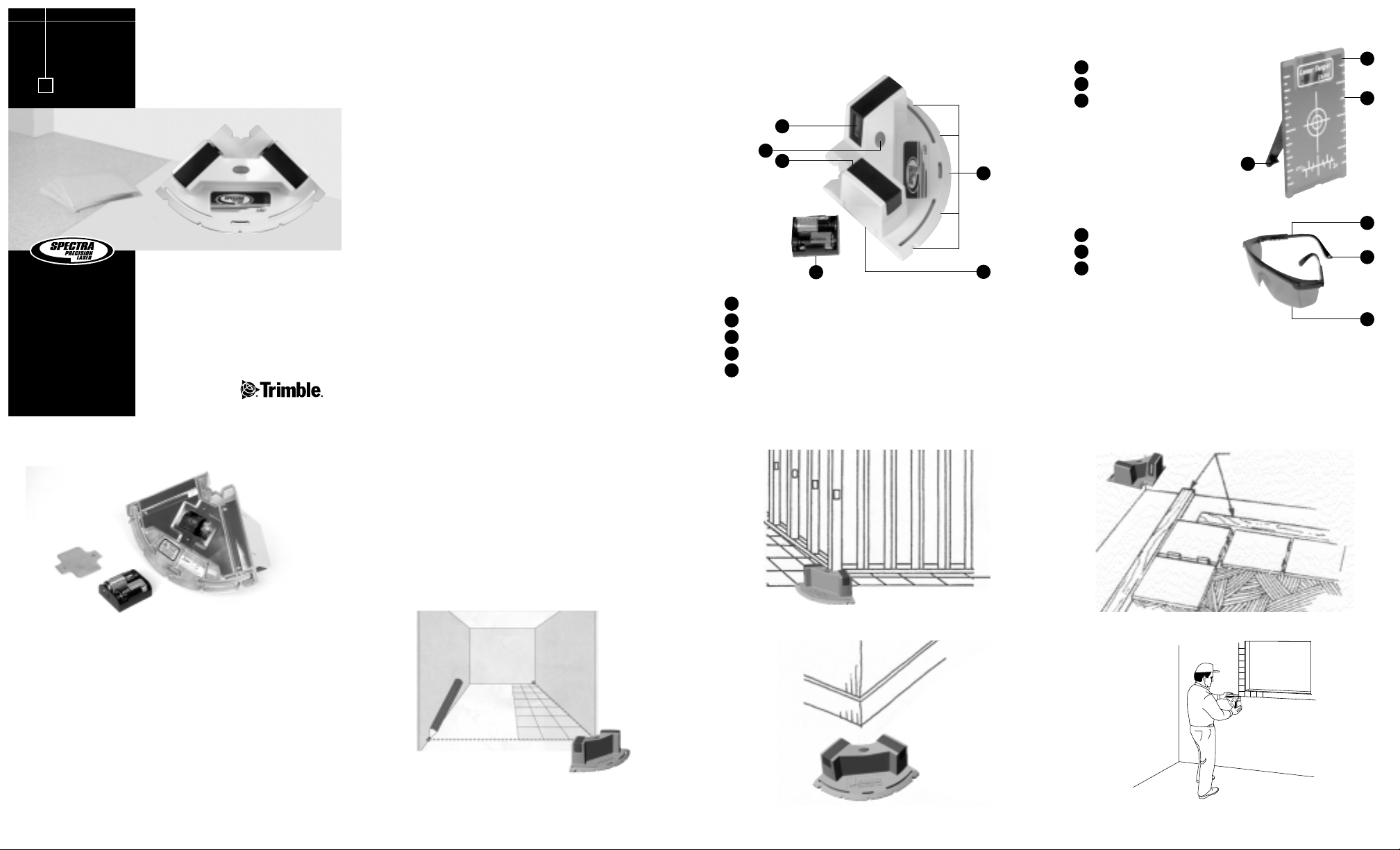
Features
Laser
Target
Reflective Surface
Reference Marks
Target Stand
Power Button
Lens
Angle References (90°, 67.5°, 45°, and 22.5°)
Battery Housing
Battery Pack
1
2
3
4
5
1
5
Laser Glasses
Adjustable Temples
Neck Cord Holes
Lens
CAUTION:The batteries should be removed when storing the laser
more than 30 days.
1. Turn the screws counterclockwise and remove the batteryhousing door.
2. Remove the battery pack from the battery housing.
3. Install/remove the 2 C-cell batteries.
Note: When installing the batteries, be sure to note the
positive (+) and negative (–) diagrams molded on the battery
pack. The laser has reverse-polarity protection so that if the
batteries are installed incorrectly, no damage occurs to the laser.
4. Insert the battery pack into the battery housing.
5. Put the battery-housing door in place. Insert the screws and turn
them clockwise.
Setting Up and Using the Laser
1. Press the power button.
2. Position the laser so that it’s appropriate for your application
needs.
3. If necessary, align the laser beam(s) with a reference point(s).
The freestanding target increases the beams’ visibility.
4. Use the laser beams as line references.
Note: When checking precision angles (90°, 67.5°, 45°, and
22.5°) or squaring walls, the laser beams can be aligned with
the walls or at an offset from them.
1
2
3
1
2
3
Checking Precision Angles
Squaring Walls Squaring Wall Cutouts & Fixtures
Installing Tile
LG2 Line Generator
User Guide
www.trimble.com
•
3
1
2
2
3
1
4
2
3
2
Wooden Batten
Page 2

– 9 – – 10 – – 11 –
–
13 – – 14 –
– 15 –
– 12 –
Establishing Common Angles
(90°, 67.5°, 45°, and 22.5°)
1. Mark the point on the floor where the laser beams intersect
(point A).
2. Using the angle references as a guide, mark the point on the floor
that corresponds to the angle you want to establish (point B).
3. Rotate the laser so that the 0°-angle reference is on point B.
Make sure that the laser beams still intersect at point A.
Increasing the Beams’ Visibility
The laser beams’ visibility can be increased when working in
really bright conditions, such as working near window openings
or outside walls.
1. Work toward the laser.
2. Use the target.
3. Use the laser glasses.
CAUTION: Do not use these glasses as safety glasses.
Note: The neck cord holes can be used to tie a string through so that
you can hang the glasses around your neck and have them available
when needed.
Note: The glasses should only be worn long enough to establish the
reference point. Wearing them longer than necessary can affect your
eyes’ sensitivity to seeing color.
Maintenance and Care
You will get years of service from your laser by following the
maintenance and care recommendations in this manual. However
well the product is designed, mishaps do occur and the most
common problems associated with these are covered in the following
areas. Any damage to the laser caused by improper maintenance and
care voids the warranty.
Handling Precautions
When transferring the laser from one location or job site to another,
be sure to carry it in its protective carrying case.
System Cleaning
For maximum performance and accuracy always keep the lenses
clean. Use only a good quality glass cleaner on a soft cloth to clean
the exterior of the laser, its lenses, and the laser glasses.
CAUTION: A dry cloth or abrasive organic cleaner could scratch or
damage these surfaces.
CAUTION: Do not submerge the laser.
Storage
When you’re not using the laser, store it in its protective case.
CAUTION: Do not store the laser in a wet case. If the case gets wet,
let it dry before storing the laser in it.
CAUTION:The batteries should be removed when storing the laser
more than 30 days.
Battery Disposal
Some states and local areas have regulations regarding the disposal of
batteries. Be sure to dispose of discharged batteries properly.
Laser Safety
This laser uses a Class 2 laser, which complies with the requirements
based on the IEC825-1/EN60825 standards (Class 2 based on
21CFR 1041). This laser may be operated without the need for any
additional protective measures. Nevertheless, as with the sun, care
should be taken to avoid looking directly into the light source.
CAUTION: Never look directly into the laser beam.
Please keep the laser out of the reach of children.
Specifications
Accuracy 6 mm @ 15 m
(1/4 in. @ 50 ft)
Working Range* 15 m nominal, up to 30 m
(50 ft nominal, up to 100 ft)
Laser Class 2
Laser Type 635 nm
Battery Type 2 C-cell alkaline
Battery Life 30 hours (alkaline)
Operating Temperature 0° to 45° C (32° to 113° F)
Range
Size (L x W x H) 36 x 30.5 x 20 cm
(14 x 12 x 8 in.)
Weight 1.3 kg (2.87 lb)
Protective Case Contains Laser, users guide, batteries,
target, and laser glasses
Warranty One year limited
*Depending on ambient condition
Checking Calibration
Before each use, be sure to check the laser for signs of damage. If the
laser has been dropped or subjected to other rough treatment, it
should be checked for accuracy.
Refer to the sketch for the location of the laser at each step and for
the location of the marks made at each step. All marks can be made
on the floor by following the beam to the floor. All marks are to the
beam center.
Locate an area at least 10 m x 5 m (30 ft x 15 ft)
1. Mark a point (A) on the floor at one end of the room.
2. Place the laser so that the laser beams intersect over point A with
one of the beams pointing toward the far end of the room.
3. Mark a point (B) on the floor at about the center of the room,
on the laser line.
Note: To ensure accuracy, the distances from B to A, to C, and
to D should be equal.
4. Mark a point (C) on the far wall close to or on the floor.
5. Place the laser so that the laser beams intersect over point B,
making sure that one of the beams is on point C. Mark point D.
6. Turn the laser 90° so that the intersecting laser beams are over
point B, making sure that one beam is over point D and the
other is pointing in the direction of point A. Mark point E as
close as possible to point A.
Existing Reference or
Chalk Line
90°
67.5°
45°
22.5°
0°
22.5°
A
90° Intersection
B
Trimble or its Authorized Service Center will repair or replace, at
its option, any defective part of components of which notice has
been given during the warranty period. A Warranty Registration
Card must be filled out properly and on file with Trimble Service
Department before warranty repair or replacement can be approved.
Travel and per diem expenses, if required, to and from the place
where repairs are made will be charged to the purchaser at the
prevailing rates.
Customers should send products to the nearest Authorized Factory
Service Center for warranty repairs, freight prepaid. In countries
with Trimble Service Subsidiary Centers, the repaired products will
be returned to the customer, freight prepaid.
Any evidence of negligent, abnormal use, accident, or any attempt to
repair equipment by other than factory-authorized personnel Trimble
certified or recommended parts, automatically voids the warranty.
Special precautions have been taken to ensure the calibration
of the laser; however, calibration is not covered by this warranty.
Maintenance of the calibration is the responsibility of the user.
The foregoing states the entire liability of Trimble regarding the
purchase and use of its equipment. Trimble will not be held
responsible for any consequential loss or damage of any kind.
This warranty is in lieu of all other warranties, except as set forth
above, including an implied warranty merchantability of fitness for
a particular purpose, is hereby disclaimed. This warranty is in lieu
of all other warranties, expressed or implied.
7. Measure the difference between points A and E and compare
with the following:
Room length or distance 90° angle is in calibration
between A and C if the distance between A
and E is:
10 m (30 ft) <3 mm (<1/8 inch)
If the difference is more than shown in the chart, contact your local
authorized service center for exchange or replacement.
C
B
A
D
E
Steps 1 & 2
Steps 3, 4, & 5
Steps 6 & 7
© 2002–2005, Trimble Navigation Limited. All rights reserved.
Reorder PN 0190-0220 Rev. C (07/05)
Warranty
Trimble warrants the Spectra Precision Laser LG2 to be free of
defects in material and workmanship for one year. This warranty
period is in effect from the date the system is delivered by Trimble
or its authorized Dealer to the purchaser, or is put into service by a
Dealer as a demonstrator or rental component.
Additionally, items covered by the standard Trimble one-year
warranty are the accessories. All other components not manufactured
Trimble but sold as a part of the system, such as tripods and grade
rods, will carry a 90 days warranty or the manufacturer’s warranty,
whichever is greater.
LASER LIGHT
DO NOT STARE
INTO BEAM
CLASS 2 LASER PRODUCT PER
IEC / EN 60825-1:2001 AND
CDRH 21 CFR 1040.10 AND 1040.11
POWER < 1 mW AVERAGE
WAVELENGTH 635-670 nm
Notice to Our European Union Customers
For product recycling instructions and more information,
please go to: www.trimble.com/environment/summary.html
Recycling in Europe
To recycle Trimble WEEE, call: +31 497 53 2430, and ask for the “WEEE
associate,” or
mail a request for recycling instructions to:
Trimble Europe BV
c/o Menlo Worldwide Logistics
Meerheide 45
5521 DZ Eersel, NL
 Loading...