

Page 1

Lassen-SK8™
Embedded GPS Module
System Designer Reference Manual
Part Number: 34149-01
Firmware: 7.20-7.52
Date: August 1997
Trimble Navigation Limited
Commercial Systems Group
645 North Mary Avenue
Post Office Box 3642
Sunnyvale, CA 94088-3642
U.S.A.
+1-800-827-8000 in North America
+1-408-481-8000 International
FAX: +1-408-730-2082
Page 2

U.S. Technical Assistance and Repair
+1-800--SOS-4-TAC in North America
+1-408-481-6940 International
FAX: +1-408-481-6020
European Technical Assistance and Repair
+44-1256-1622-858-421
Page 3

Copyrights
© 1997 Trimble Navigation Limited. All rights reserved. No part of this manual may be copied, photocopied,
reproduced, translated, or reduced to any electronic medium or machine-readable form without prior written consent
from Trimble Navigation Limited.
Printed in the United States of America. Printed on recycled paper.
Revision Notice
This is the first release of the Lassen-SK8™ Embedded GPS Module System Designer Reference Manual, Part
Number 34149-01, August 1997.
This manual supersedes the Lassen-SK8™ GPS Board for Embedded Applications, System Designer Reference
Manual, Part Number 29473-00, Revision B, June 1997, © 1996 Trimble Navigation Limited.
Trademarks
SVeeSix, SVeeSix-CM3, LASSEN-SK8, Acutis, Acutime, AcutimeII, and TSIP are trademarks of Trimble
Navigation Limited. IBM is a registered trademark of International Business Machines, Inc. MS-DOS and Windows
is a trademark of Microsoft Corporation. Intel is a trademark of Intel Corporation. All other brand names are
trademarks of their respective holders.
Disclaimer of Warranty
EXCEPT AS INDICATED IN “LIMITED WARRANTY” HEREIN, TRIMBLE HARDWARE, SOFTWARE, FIRMWARE
AND DOCUMENTATION IS PROVIDED “AS IS” AND WITHOUT EXPRESS OR LIMITED WARRANTY OF ANY KIND
BY EITHER TRIMBLE OR ANYONE WHO HAS BEEN INVOLVED IN ITS CREATION, PRODUCTION, OR
DISTRIBUTION INCLUDING BUT NOT LIMITED TO THE IMPLIED WARRANTIES OF MERCHANTABILITY AND
FITNESS FOR A PARTICULAR PURPOSE. THE ENTIRE RISK, AS TO THE QUALITY AND PERFORMANCE OF THE
TRIMBLE HARDWARE, SOFTWARE, FIRMWARE AND DOCUMENTATION, IS WITH YOU. SOME STATES DO NOT
ALLOW THE EXCLUSION OF IMPLIED WARRANTIES, SO THE ABOVE EXCLUSION MAY NOT APPLY TO YOU.
Limitation of Liability
IN NO EVENT WILL TRIMBLE OR ANY PERSON INVOLVED IN THE CREATION, PRODUCTION, OR DISTRIBUTION
OF THE TRIMBLE PRODUCT BE LIABLE TO YOU ON ACCOUNT OF ANY CLAIM FOR ANY DAMAGES, INCLUDING
ANY LOST PROFITS, LOST SAVINGS, OR OTHER SPECIAL, INCIDENTAL, CONSEQUENTIAL, OR EXEMPLARY
DAMAGES, INCLUDING BUT NOT LIMITED TO ANY DAMAGES ASSESSED AGAINST OR PAID BY YOU TO ANY
THIRD PARTY, RISING OUT OF THE USE, LIABILITY TO USE, QUALITY OR PERFORMANCE OF SUCH TRIMBLE
PRODUCT INCLUDING HARDWARE, SOFTWARE, FIRMWARE, AND DOCUMENTATION, EVEN IF TRIMBLE OR
ANY SUCH PERSON OR ENTITY HAS BEEN ADVISED OF THE POSSIBILITY OF DAMAGES, OR FOR ANY CLAIM
BY ANY OTHER PARTY. SOME STATES DO NOT ALLOW THE LIMITATION OR EXCLUSION OF LIABILITY FOR
INCIDENTAL OR CONSEQUENTIAL DAMAGES SO, THE ABOVE LIMITATIONS MAY NOT APPLY TO YOU.
Software and Firmware Limited Warranty
Trimble warrants that Software and Firmware products will substantially conform to the published specifications
provided it is used with the Trimble products, computer products, and operating system for which it was designed.
For a period of ninety (90) days, commencing thirty (30) days after shipment from Trimble, Trimble also warrants
that the magnetic media on which Software and Firmware are distributed and the documentation are free from defects
in materials and workmanship. During the ninety (90) day warranty period, Trimble will replace defective media or
documentation, or correct substantial program errors at no charge. If Trimble is unable to replace defective media or
documentation, or correct program errors, Trimble will refund the price paid for The Software. These are your sole
remedies for any breach in warranty.
Page 4

Hardware Limited Warranty
Trimble Navigation Limited products are warranted against defects in material and workmanship for a period of one
year. The warranty period shall commence thirty (30) days after shipment from Trimble’s factory. Warranty service
will be provided at a designated Trimble Service Center. Trimble will at its option either repair or replace products
that prove to be defective. The Customer shall pay all shipping charges for products returned to Trimble for warranty
service. Trimble shall pay all shipping charges for the return of products to the Customer.
This warranty shall not apply to defects resulting from one or more of the following:
• Improper or inadequate maintenance by the buyer
• Buyer-supplied software or interfacing
• Unauthorized modification or misuse
• Operation outside of the environmental specifications of the product
• Improper installation, where applicable
• Lightning or other electrical discharge
• Fresh or salt water immersion or spray
• Normal wear and tear on consumable parts (for example, batteries)
No other warranty is expressed or implied. Trimble Navigation Limited specifically disclaims the implied warranties
of fitness for a particular purpose and merchantability.
Page 5

Table of Contents
Preface
Scope and Audience . . . . . . . . . . . . . . . . . . . . . . . . . . . . . . . . . . . xix
Lassen-SK8 Manual Organization . . . . . . . . . . . . . . . . . . . . . . . . . . . . xx
Technical Assistance . . . . . . . . . . . . . . . . . . . . . . . . . . . . . . . . . . . xx
Email. . . . . . . . . . . . . . . . . . . . . . . . . . . . . . . . . . . . . . xx
Worldwide Web . . . . . . . . . . . . . . . . . . . . . . . . . . . . . . . . xxi
Internet FTP Address . . . . . . . . . . . . . . . . . . . . . . . . . . . . . xxi
FaxBack . . . . . . . . . . . . . . . . . . . . . . . . . . . . . . . . . . . . xxi
Reader Comment Form. . . . . . . . . . . . . . . . . . . . . . . . . . . . . . . . . . xxi
Document Conventions . . . . . . . . . . . . . . . . . . . . . . . . . . . . . . . . . . xxii
Notes, Tips, Cautions, and Warnings. . . . . . . . . . . . . . . . . . . . . . . . . . . xxii
1 Starter Kit
1.1 Lassen-SK8 Overview . . . . . . . . . . . . . . . . . . . . . . . . . . . . . . . . . . 1-2
1.1.1 Interface Protocols. . . . . . . . . . . . . . . . . . . . . . . . . . . . . . . 1-3
Port 1 . . . . . . . . . . . . . . . . . . . . . . . . . . . . . . . . . . . . . 1-3
Port 2 . . . . . . . . . . . . . . . . . . . . . . . . . . . . . . . . . . . . . 1-3
1.1.2 Starter Kit Components . . . . . . . . . . . . . . . . . . . . . . . . . . . . 1-3
1.2 GPS Receiver Module . . . . . . . . . . . . . . . . . . . . . . . . . . . . . . . . . . 1-5
1.3 Antenna. . . . . . . . . . . . . . . . . . . . . . . . . . . . . . . . . . . . . . . . . . 1-8
1.4 Power . . . . . . . . . . . . . . . . . . . . . . . . . . . . . . . . . . . . . . . . . . . 1-9
1.5 Hardware Setup . . . . . . . . . . . . . . . . . . . . . . . . . . . . . . . . . . . . . . 1-10
1.6 Running the TSIP Interface Program . . . . . . . . . . . . . . . . . . . . . . . . . . . 1-11
2 Hardware Integration
2.1 The Lassen-SK8 Receiver Module. . . . . . . . . . . . . . . . . . . . . . . . . . . . 2-1
2.2 Interface Connector . . . . . . . . . . . . . . . . . . . . . . . . . . . . . . . . . . . . 2-3
2.3 Power Requirement. . . . . . . . . . . . . . . . . . . . . . . . . . . . . . . . . . . . 2-3
2.4 Serial Interface . . . . . . . . . . . . . . . . . . . . . . . . . . . . . . . . . . . . . . 2-4
2.5 Pulse Per Second . . . . . . . . . . . . . . . . . . . . . . . . . . . . . . . . . . . . . 2-5
2.6 Mounting . . . . . . . . . . . . . . . . . . . . . . . . . . . . . . . . . . . . . . . . . 2-5
2.7 RF Shield . . . . . . . . . . . . . . . . . . . . . . . . . . . . . . . . . . . . . . . . . 2-5
Lassen-SK8 Embedded GPS Module v
Page 6

3 Software Interface
3.1 Start-up . . . . . . . . . . . . . . . . . . . . . . . . . . . . . . . . . . . . . . . . . . 3-1
3.2 Software Tool Kits . . . . . . . . . . . . . . . . . . . . . . . . . . . . . . . . . . . . 3-1
3.3 Communicating with the Lassen-SK8 Module. . . . . . . . . . . . . . . . . . . . . . 3-2
3.4 Protocol Summary . . . . . . . . . . . . . . . . . . . . . . . . . . . . . . . . . . . . 3-3
3.4.1 TSIP Data Output . . . . . . . . . . . . . . . . . . . . . . . . . . . . . . . 3-3
Configuring the SK 8 receiver output protocol from TSIP to TAIP protocol. 3-4
3.4.2 TAIP Data Output . . . . . . . . . . . . . . . . . . . . . . . . . . . . . . . 3-5
Configuring the SK 8 receiver output protocol from TAIP to TSIP protocol
TAIP message PR . . . . . . . . . . . . . . . . . . . . . . . . . . . . . . . 3-6
3.4.3 NMEA 0183 Data Output . . . . . . . . . . . . . . . . . . . . . . . . . . . 3-6
3.5 Timing Applications . . . . . . . . . . . . . . . . . . . . . . . . . . . . . . . . . . . 3-7
3.5.1 Effect of GPS Week Number Roll-over (WNRO) . . . . . . . . . . . . . . 3-7
Lassen/Palisade Family Firmware Version 7.xx Software Modifications . . 3-8
3.6 Differential GPS . . . . . . . . . . . . . . . . . . . . . . . . . . . . . . . . . . . . . 3-8
4 Operation and Performance
4.1 GPS Satellite Message . . . . . . . . . . . . . . . . . . . . . . . . . . . . . . . . . . 4-1
4.2 Satellite Acquisition and Time to First Fix. . . . . . . . . . . . . . . . . . . . . . . . 4-2
4.2.1 Cold-Start . . . . . . . . . . . . . . . . . . . . . . . . . . . . . . . . . . . 4-2
4.2.2 Warm Start. . . . . . . . . . . . . . . . . . . . . . . . . . . . . . . . . . . 4-2
4.2.3 Garage Search Strategy . . . . . . . . . . . . . . . . . . . . . . . . . . . . 4-3
4.2.4 Hot Start . . . . . . . . . . . . . . . . . . . . . . . . . . . . . . . . . . . . 4-3
4.3 Satellite Mask Settings . . . . . . . . . . . . . . . . . . . . . . . . . . . . . . . . . . 4-3
4.3.1 Elevation Mask . . . . . . . . . . . . . . . . . . . . . . . . . . . . . . . . 4-4
4.3.2 SNR Mask . . . . . . . . . . . . . . . . . . . . . . . . . . . . . . . . . . . 4-4
4.3.3 PDOP Mask . . . . . . . . . . . . . . . . . . . . . . . . . . . . . . . . . . 4-4
4.3.4 PDOP Switch . . . . . . . . . . . . . . . . . . . . . . . . . . . . . . . . . 4-5
4.4 Standard Operating Modes . . . . . . . . . . . . . . . . . . . . . . . . . . . . . . . . 4-5
4.4.1 Fix Modes . . . . . . . . . . . . . . . . . . . . . . . . . . . . . . . . . . . 4-5
2D Manual. . . . . . . . . . . . . . . . . . . . . . . . . . . . . . . . . . . 4-5
3D Manual. . . . . . . . . . . . . . . . . . . . . . . . . . . . . . . . . . . 4-6
2D/3D Automatic . . . . . . . . . . . . . . . . . . . . . . . . . . . . . . . 4-6
4.5 Differential GPS Operating Modes . . . . . . . . . . . . . . . . . . . . . . . . . . . . 4-6
4.5.1 DGPS On . . . . . . . . . . . . . . . . . . . . . . . . . . . . . . . . . . . 4-6
4.5.2 DGPS Off . . . . . . . . . . . . . . . . . . . . . . . . . . . . . . . . . . . 4-6
4.5.3 DGPS Automatic . . . . . . . . . . . . . . . . . . . . . . . . . . . . . . . 4-6
4.5.4 Differential GPS Operation . . . . . . . . . . . . . . . . . . . . . . . . . . 4-7
4.6 Position Accuracy . . . . . . . . . . . . . . . . . . . . . . . . . . . . . . . . . . . . 4-7
vi Lassen-SK8 Embedded GPS Module
Page 7

4.6.1 Selective Availability (SA) . . . . . . . . . . . . . . . . . . . . . . . . . . 4-7
4.6.2 Differential GPS (DGPS) . . . . . . . . . . . . . . . . . . . . . . . . . . . 4-7
4.7 Coordinate Systems. . . . . . . . . . . . . . . . . . . . . . . . . . . . . . . . . . . . 4-8
4.7.1 TSIP Coordinate Systems . . . . . . . . . . . . . . . . . . . . . . . . . . . 4-8
4.7.2 NMEA 0183 . . . . . . . . . . . . . . . . . . . . . . . . . . . . . . . . . . 4-9
4.7.3 TAIP . . . . . . . . . . . . . . . . . . . . . . . . . . . . . . . . . . . . . . 4-9
4.8 Performance Characteristics . . . . . . . . . . . . . . . . . . . . . . . . . . . . . . . 4-9
4.8.1 Update Rate . . . . . . . . . . . . . . . . . . . . . . . . . . . . . . . . . . 4-9
4.8.2 Dynamic Limits . . . . . . . . . . . . . . . . . . . . . . . . . . . . . . . . 4-9
4.8.3 Re-Acquisition. . . . . . . . . . . . . . . . . . . . . . . . . . . . . . . . . 4-9
4.9 GPS Timing. . . . . . . . . . . . . . . . . . . . . . . . . . . . . . . . . . . . . . . . 4-10
4.9.1 Serial Time Output . . . . . . . . . . . . . . . . . . . . . . . . . . . . . . 4-10
4.9.2 Timing Pulse Output (PPS) . . . . . . . . . . . . . . . . . . . . . . . . . . 4-11
4.10 System Architecture . . . . . . . . . . . . . . . . . . . . . . . . . . . . . . . . . . . 4-11
A Trimble Standard Interface Protocol
A.1 Interface Scope . . . . . . . . . . . . . . . . . . . . . . . . . . . . . . . . . . . . . . A-1
A.2 Automatic Output Packets . . . . . . . . . . . . . . . . . . . . . . . . . . . . . . . . A-2
A.3 Customizing Receiver Operations . . . . . . . . . . . . . . . . . . . . . . . . . . . . A-3
A.3.1 TAIP Customizing. . . . . . . . . . . . . . . . . . . . . . . . . . . . . . . A-3
A.3.2 NMEA Customizing. . . . . . . . . . . . . . . . . . . . . . . . . . . . . . A-3
A.3.3 Reconfiguring to Factory Default Settings . . . . . . . . . . . . . . . . . . A-3
A.4 Automatic Position and Velocity Reports . . . . . . . . . . . . . . . . . . . . . . . . A-5
A.5 Warm Start Packets. . . . . . . . . . . . . . . . . . . . . . . . . . . . . . . . . . . . A-6
A.6 Packets Output at Power-Up . . . . . . . . . . . . . . . . . . . . . . . . . . . . . . . A-7
A.7 Differential GPS Packets . . . . . . . . . . . . . . . . . . . . . . . . . . . . . . . . . A-7
A.8 Timing Packets . . . . . . . . . . . . . . . . . . . . . . . . . . . . . . . . . . . . . . A-8
A.9 Satellite Data Packets. . . . . . . . . . . . . . . . . . . . . . . . . . . . . . . . . . . A-8
A.10 Background Packets . . . . . . . . . . . . . . . . . . . . . . . . . . . . . . . . . . . A-8
A.11 Backwards Incompatibility of Lassen-SK8 Packets with Previous TSIP Versions . . . A-9
A.12 Recommended TSIP Packets. . . . . . . . . . . . . . . . . . . . . . . . . . . . . . . A-11
A.13 Command Packets Sent to the Receiver . . . . . . . . . . . . . . . . . . . . . . . . . A-13
A.14 Report Packets Sent by the GPS Receiver to the User . . . . . . . . . . . . . . . . . . A-15
A.15 Key Setup Parameters or Packet BB . . . . . . . . . . . . . . . . . . . . . . . . . . . A-16
A.15.1 Packet 0xBB - Set Fix Mode . . . . . . . . . . . . . . . . . . . . . . . . . A-17
A.15.2 Dynamics Code . . . . . . . . . . . . . . . . . . . . . . . . . . . . . . . . A-17
A.15.3 Elevation Mask . . . . . . . . . . . . . . . . . . . . . . . . . . . . . . . . A-17
A.15.4 Signal Level Mask. . . . . . . . . . . . . . . . . . . . . . . . . . . . . . . A-18
A.15.5 DOP Mask and Switch . . . . . . . . . . . . . . . . . . . . . . . . . . . . A-18
Lassen-SK8 Embedded GPS Module vii
Page 8

A.15.6 Packet 0xBB - Set DGPS Mode . . . . . . . . . . . . . . . . . . . . . . . . A-19
A.16 Packet Structure . . . . . . . . . . . . . . . . . . . . . . . . . . . . . . . . . . . . . A-19
A.17 Packet Descriptions. . . . . . . . . . . . . . . . . . . . . . . . . . . . . . . . . . . . A-20
A.17.1 Command Packet 0x1D . . . . . . . . . . . . . . . . . . . . . . . . . . . . A-20
A.17.2 Command Packet 0x1E . . . . . . . . . . . . . . . . . . . . . . . . . . . . A-20
A.17.3 Command Packet 0x1F . . . . . . . . . . . . . . . . . . . . . . . . . . . . A-20
A.17.4 Command Packet 0x21 . . . . . . . . . . . . . . . . . . . . . . . . . . . . A-20
A.17.5 Command Packet 0x23 . . . . . . . . . . . . . . . . . . . . . . . . . . . . A-21
A.17.6 Command Packet 0x24 . . . . . . . . . . . . . . . . . . . . . . . . . . . . A-21
A.17.7 Command Packet 0x25 . . . . . . . . . . . . . . . . . . . . . . . . . . . . A-21
A.17.8 Command Packet 0x26 . . . . . . . . . . . . . . . . . . . . . . . . . . . . A-21
A.17.9 Command Packet 0x27 . . . . . . . . . . . . . . . . . . . . . . . . . . . . A-21
A.17.10 Command Packet 0x28 . . . . . . . . . . . . . . . . . . . . . . . . . . . . A-21
A.17.11 Command Packet 0x2A . . . . . . . . . . . . . . . . . . . . . . . . . . . . A-22
A.17.12 Command Packet 0x2B . . . . . . . . . . . . . . . . . . . . . . . . . . . . A-23
A.17.13 Command Packet 0x2D . . . . . . . . . . . . . . . . . . . . . . . . . . . . A-23
A.17.14 Command Packet 0x2E . . . . . . . . . . . . . . . . . . . . . . . . . . . . A-23
A.17.15 Command Packet 0x31 . . . . . . . . . . . . . . . . . . . . . . . . . . . . A-24
A.17.16 Command Packet 0x32 . . . . . . . . . . . . . . . . . . . . . . . . . . . . A-24
A.17.17 Command Packet 0x35 . . . . . . . . . . . . . . . . . . . . . . . . . . . . A-24
A.17.18 Command Packet 0x37 . . . . . . . . . . . . . . . . . . . . . . . . . . . . A-26
A.17.19 Command Packet 0x38 . . . . . . . . . . . . . . . . . . . . . . . . . . . . A-27
A.17.20 Command Packet 0x39 . . . . . . . . . . . . . . . . . . . . . . . . . . . . A-28
A.17.21 Command Packet 0x3C . . . . . . . . . . . . . . . . . . . . . . . . . . . . A-28
A.17.22 Report Packet 0x41 . . . . . . . . . . . . . . . . . . . . . . . . . . . . . . A-29
A.17.23 Report Packet 0x42 . . . . . . . . . . . . . . . . . . . . . . . . . . . . . . A-30
A.17.24 Report Packet 0x43 . . . . . . . . . . . . . . . . . . . . . . . . . . . . . . A-30
A.17.25 Report Packet 0x45 . . . . . . . . . . . . . . . . . . . . . . . . . . . . . . A-31
A.17.26 Report Packet 0x46 . . . . . . . . . . . . . . . . . . . . . . . . . . . . . . A-32
A.17.27 Report Packet 0x47 . . . . . . . . . . . . . . . . . . . . . . . . . . . . . . A-33
A.17.28 Report Packet 0x48 . . . . . . . . . . . . . . . . . . . . . . . . . . . . . . A-33
A.17.29 Report Packet 0x4A . . . . . . . . . . . . . . . . . . . . . . . . . . . . . . A-33
A.17.30 Main 0x4A Report Packet Type. . . . . . . . . . . . . . . . . . . . . . . . A-34
A.17.31 Second 0x4A Packet Type. . . . . . . . . . . . . . . . . . . . . . . . . . . A-34
Reference Altitude. . . . . . . . . . . . . . . . . . . . . . . . . . . . . . . A-34
Altitude Flag. . . . . . . . . . . . . . . . . . . . . . . . . . . . . . . . . . A-35
A.17.32 Report Packet 0x4B . . . . . . . . . . . . . . . . . . . . . . . . . . . . . . A-35
A.17.33 Report Packet 0x4D . . . . . . . . . . . . . . . . . . . . . . . . . . . . . . A-36
A.17.34 Report Packet 0x4E . . . . . . . . . . . . . . . . . . . . . . . . . . . . . . A-36
viii Lassen-SK8 Embedded GPS Module
Page 9

A.17.35 Report Packet 0x55 . . . . . . . . . . . . . . . . . . . . . . . . . . . . . . A-37
A.17.36 Report Packet 0x56 . . . . . . . . . . . . . . . . . . . . . . . . . . . . . . A-39
A.17.37 Report Packet 0x57 . . . . . . . . . . . . . . . . . . . . . . . . . . . . . . A-39
A.17.38 Report Packet 0x58 . . . . . . . . . . . . . . . . . . . . . . . . . . . . . . A-40
A.17.39 Report Packet 0x59 . . . . . . . . . . . . . . . . . . . . . . . . . . . . . . A-44
A.17.40 Report Packet 0x5A . . . . . . . . . . . . . . . . . . . . . . . . . . . . . . A-45
A.17.41 Report Packet 0x5C . . . . . . . . . . . . . . . . . . . . . . . . . . . . . . A-47
A.17.42 Command Packet 0x60 -. . . . . . . . . . . . . . . . . . . . . . . . . . . . Type
1 Differential GPS CorrectionsA-48
A.17.43 Command Packet 0x61 -. . . . . . . . . . . . . . . . . . . . . . . . . . . . Set
Differential GPS CorrectionsA-49
A.17.44 Command Packet 0x62 . . . . . . . . . . . . . . . . . . . . . . . . . . . . A-49
A.17.45 Command Packet 0x65 . . . . . . . . . . . . . . . . . . . . . . . . . . . . A-50
A.17.46 Report Packet 0x6D . . . . . . . . . . . . . . . . . . . . . . . . . . . . . . A-50
A.17.47 Command Packet 0x6E — Set or Request Synchronized
Measurement Parameters . . . . . . . . . . . . . . . . . . . . . . . . . . . A-51
Enable / Disable Synchronized Measurements . . . . . . . . . . . . . . . . A-51
Output Level. . . . . . . . . . . . . . . . . . . . . . . . . . . . . . . . . . A-51
A.17.48 Report Packet 0x6E — Synchronized Measurements. . . . . . . . . . . . . A-52
A.17.49 Report Packet 0x6F, Subcode 1 . . . . . . . . . . . . . . . . . . . . . . . . A-52
A.17.50 Command Packet 0x70 . . . . . . . . . . . . . . . . . . . . . . . . . . . . A-54
A.17.51 Report 0x70 . . . . . . . . . . . . . . . . . . . . . . . . . . . . . . . . . . A-54
A.17.52 Command Packet 0x7A . . . . . . . . . . . . . . . . . . . . . . . . . . . . A-55
A.17.53 Report Packet 0x7B . . . . . . . . . . . . . . . . . . . . . . . . . . . . . . A-56
A.17.54 Report Packet 0x82 . . . . . . . . . . . . . . . . . . . . . . . . . . . . . . A-56
A.17.55 Report Packet 0x83 . . . . . . . . . . . . . . . . . . . . . . . . . . . . . . A-57
A.17.56 Report Packet 0x84 . . . . . . . . . . . . . . . . . . . . . . . . . . . . . . A-57
A.17.57 Report Packet 0x85 . . . . . . . . . . . . . . . . . . . . . . . . . . . . . . A-58
A.17.58 Packets 0x8E and 0x8F . . . . . . . . . . . . . . . . . . . . . . . . . . . . A-58
A.17.59 Command Packet 0xBB. . . . . . . . . . . . . . . . . . . . . . . . . . . . A-59
A.17.60 Report Packet 0xBB . . . . . . . . . . . . . . . . . . . . . . . . . . . . . . A-60
A.17.61 Command Packet 0xBC. . . . . . . . . . . . . . . . . . . . . . . . . . . . A-60
A.17.62 Report Packet 0xBC . . . . . . . . . . . . . . . . . . . . . . . . . . . . . . A-61
A.18 TSIP Superpackets . . . . . . . . . . . . . . . . . . . . . . . . . . . . . . . . . . . . A-62
A.18.1 Command Packet 0x8E-15 - Set/Request Datum . . . . . . . . . . . . . . . A-62
A.18.2 Command Packet 0x8E-19 . . . . . . . . . . . . . . . . . . . . . . . . . . A-64
A.18.3 Command Packet 0x8E-20 . . . . . . . . . . . . . . . . . . . . . . . . . . A-64
A.18.4 Command Packet 0x8E-26 . . . . . . . . . . . . . . . . . . . . . . . . . . A-65
A.18.5 Report Packet 0x8F-15 - Current Datum Values . . . . . . . . . . . . . . . A-65
A.18.6 Report Packet 0x8F-17 . . . . . . . . . . . . . . . . . . . . . . . . . . . . A-66
Lassen-SK8 Embedded GPS Module ix
Page 10

A.18.7 Report Packet 0x8F-18 . . . . . . . . . . . . . . . . . . . . . . . . . . . . A-66
A.18.8 Report Packet 0x8F-19 . . . . . . . . . . . . . . . . . . . . . . . . . . . . A-67
A.18.9 Report Packet 0x8F-20 . . . . . . . . . . . . . . . . . . . . . . . . . . . . A-67
A.18.10 Report Packet 0x8F-26 . . . . . . . . . . . . . . . . . . . . . . . . . . . . A-69
A.19 Datums . . . . . . . . . . . . . . . . . . . . . . . . . . . . . . . . . . . . . . . . . . A-70
A.20 Reference Documents . . . . . . . . . . . . . . . . . . . . . . . . . . . . . . . . . . A-75
B TSIP User's Guide
C Trimble ASCII Interface Protocol (TAIP)
C.1 Message Format . . . . . . . . . . . . . . . . . . . . . . . . . . . . . . . . . . . . . C-2
C.1.1 Start of a New Message . . . . . . . . . . . . . . . . . . . . . . . . . . . . C-2
C.1.2 Message Qualifier . . . . . . . . . . . . . . . . . . . . . . . . . . . . . . . C-2
C.1.3 Message Identifier . . . . . . . . . . . . . . . . . . . . . . . . . . . . . . . C-3
C.1.4 Data String. . . . . . . . . . . . . . . . . . . . . . . . . . . . . . . . . . . C-3
C.1.5 Vehicle ID . . . . . . . . . . . . . . . . . . . . . . . . . . . . . . . . . . . C-3
C.1.6 Checksum . . . . . . . . . . . . . . . . . . . . . . . . . . . . . . . . . . . C-3
C.1.7 Message Delimiter. . . . . . . . . . . . . . . . . . . . . . . . . . . . . . . C-3
C.2 Sample PV Message . . . . . . . . . . . . . . . . . . . . . . . . . . . . . . . . . . . C-4
C.3 Time and Distance Reporting . . . . . . . . . . . . . . . . . . . . . . . . . . . . . . C-5
C.4 Latitude and Longitude Conversion . . . . . . . . . . . . . . . . . . . . . . . . . . . C-6
C.5 Message Data Strings. . . . . . . . . . . . . . . . . . . . . . . . . . . . . . . . . . . C-7
C.23 Communication Using TAIP . . . . . . . . . . . . . . . . . . . . . . . . . . . . . . . C-27
C.23.1 Query for Single Sentence. . . . . . . . . . . . . . . . . . . . . . . . . . . C-27
C.23.2 The Response to Query or Scheduled Report . . . . . . . . . . . . . . . . . C-27
C.23.3 The Set Qualifier . . . . . . . . . . . . . . . . . . . . . . . . . . . . . . . C-28
C.23.4 Sample Communication Session . . . . . . . . . . . . . . . . . . . . . . . C-28
D GPSSK User's Guide (TAIP)
D.1 The GPSSK Files . . . . . . . . . . . . . . . . . . . . . . . . . . . . . . . . . . . . D-1
D.2 TAIP.C Source File. . . . . . . . . . . . . . . . . . . . . . . . . . . . . . . . . . . . D-2
D.3 GPSSK Start-up . . . . . . . . . . . . . . . . . . . . . . . . . . . . . . . . . . . . . D-2
D.4 On-line Help . . . . . . . . . . . . . . . . . . . . . . . . . . . . . . . . . . . . . . . D-2
D.5 Connecting the GPS Sensor . . . . . . . . . . . . . . . . . . . . . . . . . . . . . . . D-3
E NMEA 0183
E.1 The NMEA 0183 Communication Interface . . . . . . . . . . . . . . . . . . . . . . . E-1
E.2 NMEA 0183 Message Format . . . . . . . . . . . . . . . . . . . . . . . . . . . . . . E-2
E.3 NMEA 0183 Message Options . . . . . . . . . . . . . . . . . . . . . . . . . . . . . . E-2
x Lassen-SK8 Embedded GPS Module
Page 11

E.4 NMEA 0183 Message Formats. . . . . . . . . . . . . . . . . . . . . . . . . . . . . . E-3
E.4.1 GGA - GPS Fix Data . . . . . . . . . . . . . . . . . . . . . . . . . . . . . E-3
E.4.2 GLL - Geographic Position - Latitude/Longitude. . . . . . . . . . . . . . . E-4
E.4.3 GSA - GPS DOP and Active Satellites . . . . . . . . . . . . . . . . . . . . E-4
E.4.4 GSV - GPS Satellites in View. . . . . . . . . . . . . . . . . . . . . . . . . E-5
E.4.5 RMC - Recommended Minimum Specific GPS/Transit Data. . . . . . . . . E-6
E.4.6 VTG - Track Made Good and Ground Speed . . . . . . . . . . . . . . . . . E-6
E.4.7 ZDA - Time & Date . . . . . . . . . . . . . . . . . . . . . . . . . . . . . . E-7
F Specifications and Mechanical Drawings
F.1 GPS Receiver. . . . . . . . . . . . . . . . . . . . . . . . . . . . . . . . . . . . . . . F-1
F.1.1 General . . . . . . . . . . . . . . . . . . . . . . . . . . . . . . . . . . . . . F-1
F.1.2 Accuracy. . . . . . . . . . . . . . . . . . . . . . . . . . . . . . . . . . . . F-1
F.1.3 DGPS Accuracy . . . . . . . . . . . . . . . . . . . . . . . . . . . . . . . . F-1
F.1.4 Datum . . . . . . . . . . . . . . . . . . . . . . . . . . . . . . . . . . . . . F-1
F.1.5 Acquisition Rate . . . . . . . . . . . . . . . . . . . . . . . . . . . . . . . . F-2
F.1.6 Dynamics . . . . . . . . . . . . . . . . . . . . . . . . . . . . . . . . . . . F-2
F.2 Environmental Characteristics . . . . . . . . . . . . . . . . . . . . . . . . . . . . . . F-2
F.2.1 Temperature . . . . . . . . . . . . . . . . . . . . . . . . . . . . . . . . . . F-2
F.2.2 Vibration. . . . . . . . . . . . . . . . . . . . . . . . . . . . . . . . . . . . F-2
F.2.3 Altitude . . . . . . . . . . . . . . . . . . . . . . . . . . . . . . . . . . . . F-2
F.2.4 Humidity. . . . . . . . . . . . . . . . . . . . . . . . . . . . . . . . . . . . F-2
F.3 Physical Characteristics . . . . . . . . . . . . . . . . . . . . . . . . . . . . . . . . . F-3
F.3.1 Size . . . . . . . . . . . . . . . . . . . . . . . . . . . . . . . . . . . . . . F-3
F.3.2 Weight . . . . . . . . . . . . . . . . . . . . . . . . . . . . . . . . . . . . . F-3
F.3.3 Power . . . . . . . . . . . . . . . . . . . . . . . . . . . . . . . . . . . . . F-3
F.4 Input/Output . . . . . . . . . . . . . . . . . . . . . . . . . . . . . . . . . . . . . . . F-3
F.4.1 Interface . . . . . . . . . . . . . . . . . . . . . . . . . . . . . . . . . . . . F-3
F.4.2 Protocols Available . . . . . . . . . . . . . . . . . . . . . . . . . . . . . . F-3
F.5 Pulse Per Second . . . . . . . . . . . . . . . . . . . . . . . . . . . . . . . . . . . . . F-4
F.5.1 Timing . . . . . . . . . . . . . . . . . . . . . . . . . . . . . . . . . . . . . F-4
F.5.2 Pulse Width . . . . . . . . . . . . . . . . . . . . . . . . . . . . . . . . . . F-4
F.5.3 Output . . . . . . . . . . . . . . . . . . . . . . . . . . . . . . . . . . . . . F-4
F.6 RF Interference . . . . . . . . . . . . . . . . . . . . . . . . . . . . . . . . . . . . . . F-4
F.6.1 Jamming . . . . . . . . . . . . . . . . . . . . . . . . . . . . . . . . . . . . F-4
F.6.2 Burnout . . . . . . . . . . . . . . . . . . . . . . . . . . . . . . . . . . . . F-4
F.7 Lassen-SK8 Crystal Specifications. . . . . . . . . . . . . . . . . . . . . . . . . . . . F-5
F.7.1 Electrical. . . . . . . . . . . . . . . . . . . . . . . . . . . . . . . . . . . . F-5
F.7.2 Environmental . . . . . . . . . . . . . . . . . . . . . . . . . . . . . . . . . F-5
Lassen-SK8 Embedded GPS Module xi
Page 12

F.7.3 Mechanical . . . . . . . . . . . . . . . . . . . . . . . . . . . . . . . . . . . F-5
Glossary
Index
xii Lassen-SK8 Embedded GPS Module
Page 13

List of Figures
Figure 1-1. The Module Installed Inside the Interface Unit . . . . . . . . . . . . . . . . . . . 1-5
Figure 1-2. Receiver Module . . . . . . . . . . . . . . . . . . . . . . . . . . . . . . . . . . . 1-6
Figure 1-3. Starter Kit Interface Unit . . . . . . . . . . . . . . . . . . . . . . . . . . . . . . . 1-7
Figure 1-4. Open Collector PPS . . . . . . . . . . . . . . . . . . . . . . . . . . . . . . . . . 1-7
Figure 1-5. Magnetic Mount GPS Antenna. . . . . . . . . . . . . . . . . . . . . . . . . . . . 1-8
Figure 1-6. Hard Mount GPS Antenna . . . . . . . . . . . . . . . . . . . . . . . . . . . . . . 1-8
Figure 1-7. Bullet II GPS Antenna . . . . . . . . . . . . . . . . . . . . . . . . . . . . . . . . 1-9
Figure 1-8. DC Power Cable . . . . . . . . . . . . . . . . . . . . . . . . . . . . . . . . . . . 1-9
Figure 1-9. AC/DC Power Converter. . . . . . . . . . . . . . . . . . . . . . . . . . . . . . . 1-10
Figure 1-10. Interconnect Diagram . . . . . . . . . . . . . . . . . . . . . . . . . . . . . . . . 1-11
Figure 1-11. TSIPCHAT Command Window and Report Window . . . . . . . . . . . . . . . . 1-12
Figure 2-1. Motherboard Connection Points . . . . . . . . . . . . . . . . . . . . . . . . . . . 2-1
Figure 2-2. Removing the Receiver Module . . . . . . . . . . . . . . . . . . . . . . . . . . . 2-2
Figure 2-3. Interface Connector Pin Identification . . . . . . . . . . . . . . . . . . . . . . . . 2-3
Figure 4-1. Lassen-SK8 Block Diagram . . . . . . . . . . . . . . . . . . . . . . . . . . . . . 4-12
Figure F-1. Lassen-SK8 Mechanical Drawing - Circuit Board and Shield. . . . . . . . . . . . F-6
Figure F-2. Lassen-SK8 Mechanical Drawing - Motherboard Schematic . . . . . . . . . . . . F-7
Figure F-3. Lassen-SK8 Mechanical Drawing - Miniature Antenna . . . . . . . . . . . . . . . F-8
Figure F-4. Lassen-SK8 Mechanical Drawing - Trimble Bulkhead Antenna . . . . . . . . . . F-9
Figure F-5. Lassen-SK8 Mechanical Drawing - Bullet II Antenna . . . . . . . . . . . . . . . . F-10
Lassen-SK8 Embedded GPS Module xiii
Page 14

xiv Lassen-SK8 Embedded GPS Module
Page 15

List of Tables
Table 1-1. Lassen-SK8 Starter Kit. . . . . . . . . . . . . . . . . . . . . . . . . . . . . . . . 1-4
Table 1-2. Lassen-SK8 Modules. . . . . . . . . . . . . . . . . . . . . . . . . . . . . . . . . 1-4
Table 1-3. Lassen SK-8 Optional Antennas . . . . . . . . . . . . . . . . . . . . . . . . . . . 1-4
Table 2-1. I/O Connector Signals . . . . . . . . . . . . . . . . . . . . . . . . . . . . . . . . 2-3
Table 2-2. Power Requirements . . . . . . . . . . . . . . . . . . . . . . . . . . . . . . . . . 2-4
Table 3-1. Default Serial Port Characteristics . . . . . . . . . . . . . . . . . . . . . . . . . . 3-2
Table 3-2. TSIP Message Description . . . . . . . . . . . . . . . . . . . . . . . . . . . . . . 3-6
Table 4-1. Default Satellite Mask Settings. . . . . . . . . . . . . . . . . . . . . . . . . . . . 4-3
Table 4-2. Lassen-SK8 Operating Limits . . . . . . . . . . . . . . . . . . . . . . . . . . . . 4-9
Table A-1. Automatic Output Packets . . . . . . . . . . . . . . . . . . . . . . . . . . . . . . A-2
Table A-2. Customizing Receiver Operation I/Os . . . . . . . . . . . . . . . . . . . . . . . . A-4
Table A-3. Automatic Position and Velocity Reports Control Setting Bits . . . . . . . . . . . A-5
Table A-4. Warm Start Packet Commands. . . . . . . . . . . . . . . . . . . . . . . . . . . . A-6
Table A-5. Packet Power-up Output Messages. . . . . . . . . . . . . . . . . . . . . . . . . . A-7
Table A-6. Differential GPS Packet TSIP Control Commands . . . . . . . . . . . . . . . . . A-7
Table A-7. Timing Packet TSIP Control Commands . . . . . . . . . . . . . . . . . . . . . . A-8
Table A-8. Satellite Date Packet Data I/O Descriptions . . . . . . . . . . . . . . . . . . . . . A-8
Table A-9. Background Packet Output Messages . . . . . . . . . . . . . . . . . . . . . . . . A-8
Table A-10. Supported Auto-Output Packet Command Backward Compatibility . . . . . . . . A-9
Table A-11. TSIP Command Backward Incompatibility . . . . . . . . . . . . . . . . . . . . . A-10
Table A-12. Recommended TSIP Packet Data . . . . . . . . . . . . . . . . . . . . . . . . . . A-11
Table A-13. User-Selected Command Packet Options . . . . . . . . . . . . . . . . . . . . . . A-13
Table A-14. User-Selected Report Packet Options . . . . . . . . . . . . . . . . . . . . . . . . A-15
Table A-15. Setup Parameters . . . . . . . . . . . . . . . . . . . . . . . . . . . . . . . . . . . A-16
Table A-16. Command Packet 0x1E Format . . . . . . . . . . . . . . . . . . . . . . . . . . . A-20
Table A-17 Command Packet 0x23 Data Format. . . . . . . . . . . . . . . . . . . . . . . . . A-21
Table A-18. Packet 0x2A Set Altitude Only Description . . . . . . . . . . . . . . . . . . . . . A-22
Table A-19. Reset Altitude Flag Description . . . . . . . . . . . . . . . . . . . . . . . . . . . A-22
Table A-20. Command Packet 0x23 Data Format. . . . . . . . . . . . . . . . . . . . . . . . . A-23
Table A-21. Command Packet 0x2E Data Formats . . . . . . . . . . . . . . . . . . . . . . . . A-23
Table A-22. Command Packets 0x35 and 0x55 Data Descriptions . . . . . . . . . . . . . . . . A-25
Table A-23. Command Packet 0x38 Data Formats . . . . . . . . . . . . . . . . . . . . . . . . A-27
Lassen-SK8 Embedded GPS Module xv
Page 16

Table A-24. Command Packet 0x39 Data Formats . . . . . . . . . . . . . . . . . . . . . . . . A-28
Table A-25. Command Packet 0x3C Data Format. . . . . . . . . . . . . . . . . . . . . . . . . A-28
Table A-26. Report Packet 0x41 Data Formats . . . . . . . . . . . . . . . . . . . . . . . . . . A-29
Table A-27. Packets 0x41 and 0x46 Status Code Relationships. . . . . . . . . . . . . . . . . . A-29
Table A-28. Report Packet 0x42 Data Formats . . . . . . . . . . . . . . . . . . . . . . . . . . A-30
Table A-29. Report Packet 0x43 Data Formats . . . . . . . . . . . . . . . . . . . . . . . . . . A-30
Table A-30. Report Packet 0x45 Data Formats . . . . . . . . . . . . . . . . . . . . . . . . . . A-31
Table A-31. Report Packet 0x46 Data Formats . . . . . . . . . . . . . . . . . . . . . . . . . . A-32
Table A-32. Report Packet 0x46 Bit Positions and Descriptions . . . . . . . . . . . . . . . . . A-32
Table A-33. Report Packet 0x47 Data Formats . . . . . . . . . . . . . . . . . . . . . . . . . . A-33
Table A-34. Report Packet 0x4A Data Formats . . . . . . . . . . . . . . . . . . . . . . . . . . A-34
Table A-35. Reference Altitude . . . . . . . . . . . . . . . . . . . . . . . . . . . . . . . . . . A-35
Table A-36. Report Packet 0x4B Data Formats . . . . . . . . . . . . . . . . . . . . . . . . . . A-35
Table A-37. Report Packet 0x4B Bit Positions and Descriptions . . . . . . . . . . . . . . . . . A-35
Table A-38. Report Packet 0x4E Data Formats . . . . . . . . . . . . . . . . . . . . . . . . . . A-36
Table A-39. Command Packets 0x55 and 0x35 Data Descriptions . . . . . . . . . . . . . . . . A-37
Table A-40. Report Packet 0x56 Data Formats . . . . . . . . . . . . . . . . . . . . . . . . . . A-39
Table A-41. Report Packet 0x57 Data Formats . . . . . . . . . . . . . . . . . . . . . . . . . . A-39
Table A-42. Report Packet 0x58 Data Formats . . . . . . . . . . . . . . . . . . . . . . . . . . A-40
Table A-43. Report Packet 0x58 Almanac Data . . . . . . . . . . . . . . . . . . . . . . . . . . A-41
Table A-44. Report Packet 0x58 Almanac Health Data . . . . . . . . . . . . . . . . . . . . . . A-41
Table A-45. Report Packet 0x58 Ionosphere Data. . . . . . . . . . . . . . . . . . . . . . . . . A-42
Table A-46. Report Packet 0x58 UTC Data . . . . . . . . . . . . . . . . . . . . . . . . . . . . A-42
Table A-47. Report Packet 0x58 Ephemeris Data . . . . . . . . . . . . . . . . . . . . . . . . . A-42
Table A-48. Report Packet 0x59 Data Formats . . . . . . . . . . . . . . . . . . . . . . . . . . A-44
Table A-49. Report Packet 0x5A Data Formats . . . . . . . . . . . . . . . . . . . . . . . . . . A-45
Table A-50. Report Packet 0x5C Data Formats . . . . . . . . . . . . . . . . . . . . . . . . . . A-47
Table A-51. Report Packet 0x60 Data Formats . . . . . . . . . . . . . . . . . . . . . . . . . . A-48
Table A-52. Report Packet 0x60 Data Formats for Health and Power . . . . . . . . . . . . . . A-48
Table A-53. Command Packet 0x61 Data Formats . . . . . . . . . . . . . . . . . . . . . . . . A-49
Table A-54. Report Packet 0x6D Data Formats . . . . . . . . . . . . . . . . . . . . . . . . . . A-50
Table A-55. Set Synchronized Measurement Parameters . . . . . . . . . . . . . . . . . . . . . A-51
Table A-56. Request Synchronized Measurement Parameters . . . . . . . . . . . . . . . . . . A-51
Table A-57. Set Synchronized Measurement Parameters . . . . . . . . . . . . . . . . . . . . . A-52
Table A-58 Synchronized Measurements Report . . . . . . . . . . . . . . . . . . . . . . . . . A-52
Table A-59 FLAGS1 Bit Assignments . . . . . . . . . . . . . . . . . . . . . . . . . . . . . . A-53
Table A-60. Command and Report Packet 0x70 Field Descriptions . . . . . . . . . . . . . . . A-54
Table A-61. Command Packet 0x7A Data Formats . . . . . . . . . . . . . . . . . . . . . . . . A-55
xvi Lassen-SK8 Embedded GPS Module
Page 17

Table A-62. Command Packet 0x7A Data Formats for Setting NMEA Interval and Message MaskA55
Table A-63. Report Packet 0x7B Message Mask Settings . . . . . . . . . . . . . . . . . . . . A-56
Table A-64. Report Packet 0x83 Data Formats . . . . . . . . . . . . . . . . . . . . . . . . . . A-57
Table A-65. Report Packet 0x84 Data Formats . . . . . . . . . . . . . . . . . . . . . . . . . . A-57
Table A-66. Report Packet 0x85 Data Formats . . . . . . . . . . . . . . . . . . . . . . . . . . A-58
Table A-67. Report Packet 0x85 Summary Status Code Encoding . . . . . . . . . . . . . . . . A-58
Table A-68. Command Packet 0xBB Query Mode Data Format . . . . . . . . . . . . . . . . . A-59
Table A-69. Command and Report Packet 0xBB Field Descriptions . . . . . . . . . . . . . . . A-59
Table A-70. Command Packet 0xBC Port Characteristics Query Field Descriptions. . . . . . . A-60
Table A-71. Command Packet 0xBC Field Descriptions . . . . . . . . . . . . . . . . . . . . . A-60
Table A-72. Report Packet 0xBC Field Descriptions . . . . . . . . . . . . . . . . . . . . . . . A-61
Table A-73. Command Packet 0x8E-15 Field Descriptions. . . . . . . . . . . . . . . . . . . . A-63
Table A-74. Command Packet 0x8E-15 Datum Index Field Descriptions . . . . . . . . . . . . A-63
Table A-75. Command Packet 0x8E-15 Eccentricity of the Ellipse Parameter Field Descriptions A-63
Table A-76. Command Packet 0x8E-19Field Description . . . . . . . . . . . . . . . . . . . . A-64
Table A-77. Command Packet 0x8E-20 Field Descriptions. . . . . . . . . . . . . . . . . . . . A-64
Table A-78. Command Packet 0x8E-26 Definitions . . . . . . . . . . . . . . . . . . . . . . . A-65
Table A-79. Report Packet 0x8F-15 Field Descriptions for Converting Ellipsoid
ECFF XYZ to Coordinate System LLA . . . . . . . . . . . . . . . . . . . . . . . A-65
Table A-80. Report Packet 0x8F-17 Field Descriptions. . . . . . . . . . . . . . . . . . . . . . A-66
Table A-81. Report Packet 8F-18 Field Descriptions . . . . . . . . . . . . . . . . . . . . . . . A-67
Table A-82. Command Packet 0x8F-19 Field Descriptions . . . . . . . . . . . . . . . . . . . . A-67
Table A-83. Report Packet 0x8F-20 Data formats. . . . . . . . . . . . . . . . . . . . . . . . . A-67
Table A-84. Report Packet 0x8F-20 Fix SVs . . . . . . . . . . . . . . . . . . . . . . . . . . . A-69
Table A-85. Report Packet 0x8F-26 Field Descriptions. . . . . . . . . . . . . . . . . . . . . . A-69
Table A-86. Datums . . . . . . . . . . . . . . . . . . . . . . . . . . . . . . . . . . . . . . . . A-70
Table C-1. Message Formats . . . . . . . . . . . . . . . . . . . . . . . . . . . . . . . . . . . C-2
Table C-2 Message Format Qualifiers. . . . . . . . . . . . . . . . . . . . . . . . . . . . . . C-2
Table C-3. Time and Distance Reporting Message Format Qualifiers. . . . . . . . . . . . . . C-4
Table C-4. Time and Distance Reporting Message Format Qualifiers. . . . . . . . . . . . . . C-5
Table C-5. Message Data String Descriptions . . . . . . . . . . . . . . . . . . . . . . . . . . C-7
Table C-6. Altitude/Up Velocity Data String Descriptions . . . . . . . . . . . . . . . . . . . C-8
Table C-7. Auxiliary Port Characteristics Data String Descriptions. . . . . . . . . . . . . . . C-9
Table C-8. Compact Position Solutions Data String Descriptions . . . . . . . . . . . . . . . . C-10
Table C-9. RTCM-104 Record Types 1 and 9 Data String Descriptions . . . . . . . . . . . . C-11
Table C-10. Delta Differential Corrections Data String Descriptions. . . . . . . . . . . . . . . C-12
Table C-11. Delta Differential Corrections Data String Descriptions. . . . . . . . . . . . . . . C-13
Table C-12. Identification Number Data String Descriptions . . . . . . . . . . . . . . . . . . . C-14
Table C-13. Initial Position Data String Descriptions . . . . . . . . . . . . . . . . . . . . . . . C-15
Lassen-SK8 Embedded GPS Module xvii
Page 18

Table C-14. Long Navigation Message Data String Descriptions. . . . . . . . . . . . . . . . . C-16
Table C-15. PR Data String Descriptions . . . . . . . . . . . . . . . . . . . . . . . . . . . . . C-17
Table C-16. Port Characteristic Data String Descriptions . . . . . . . . . . . . . . . . . . . . . C-18
Table C-17. Position/Velocity Solution Data String Descriptions. . . . . . . . . . . . . . . . . C-19
Table C-18. IReporting Mode Data String Descriptions. . . . . . . . . . . . . . . . . . . . . . C-20
Table C-19. Reset Mode Data String Descriptions . . . . . . . . . . . . . . . . . . . . . . . . C-21
Table C-20. IData String Hex Characters . . . . . . . . . . . . . . . . . . . . . . . . . . . . . C-22
Table C-21. Tracking Status Code . . . . . . . . . . . . . . . . . . . . . . . . . . . . . . . . . C-22
Table C-22. Error Codes: Nibble 1 . . . . . . . . . . . . . . . . . . . . . . . . . . . . . . . . C-23
Table C-23. Error codes: Nibble 2 . . . . . . . . . . . . . . . . . . . . . . . . . . . . . . . . . C-23
Table C-24. Error Codes – Nibble 4 . . . . . . . . . . . . . . . . . . . . . . . . . . . . . . . . C-24
Table C-25. TM Time/Data Data String Descriptions . . . . . . . . . . . . . . . . . . . . . . . C-25
Table C-26. Version Number Data String Descriptions . . . . . . . . . . . . . . . . . . . . . . C-26
Table E-1. NMEA 0183 Characteristics . . . . . . . . . . . . . . . . . . . . . . . . . . . . . E-1
Table E-2. Lassen-SK8 NMEA Messages . . . . . . . . . . . . . . . . . . . . . . . . . . . . E-3
Table E-3. GGA - GPS Fix Data Message Parameters. . . . . . . . . . . . . . . . . . . . . . E-3
Table E-4. GLL - Geographic Position - Latitude / Longitude Message Parameters . . . . . . E-4
Table E-5. GSA - GPS DOP and Active Satellites Message Parameters . . . . . . . . . . . . E-4
Table E-6. GSV - GPS Satellites in View Message Parameters . . . . . . . . . . . . . . . . . E-5
Table E-7. RMC - Recommended Minimum Specific GPS / Transit Data Message Parameters E-6
Table E-8. VTG - Track Made Good and Ground Speed Message Parameters . . . . . . . . . E-6
Table E-9. ZDA - Time & Date Message Parameters . . . . . . . . . . . . . . . . . . . . . . E-7
xviii Lassen-SK8 Embedded GPS Module
Page 19

Preface
The Global Positioning System (GPS) is a satellite based navigation system operated and
maintained by the U.S. Department of Defense. The GPS consists of a constellation of 24
satellites providing world-wide, 24 hour, three dimensional (3-D) coverage. Although
originally conceived for military needs, GPS has a broad array of civilian applications
including surveying, marine, land, aviation, and vehicle navigation. GPS is the most
accurate technology available for vehicle navigation.
As a satellite based system, GPS is immune to the limitations of land based systems such
as Loran. Loran navigation is limited in coverage and is encumbered by adverse weather.
In addition, the accuracy of Loran navigation varies with geographic location and, even
under ideal conditions, cannot compare with GPS. By computing the distance to GPS
satellites orbiting the earth, a GPS receiver can calculate an accurate position. This process
is called satellite ranging. A 2-D position calculation requires three satellite ranges. A 3-D
position calculation, which includes altitude, requires four satellite ranges. GPS receivers
can also provide precise time, speed, and course measurements which are beneficial for
vehicle navigation.
Differential GPS (DGPS) is a sophisticated form of GPS navigation which provides even
greater positioning accuracy. Differential GPS relies on error corrections transmitted from
a GPS receiver placed at a known location. This receiver, called a reference station,
calculates the error in the satellite range data and outputs corrections for use by other GPS
receivers. These GPS receivers are designated as mobile units and can be dispersed as far
as 100 Km from the base station. Differential GPS eliminates virtually all the
measurement error in the satellite ranges and enables a highly accurate position
calculation. The Lassen-SK8 is differential-ready for applications requiring DGPS
accuracy.
Scope and Audience
Even if you have used other Global Positioning System (GPS) receivers, we recommend
that you spend some time reading this manual. The following section provides you with a
guide to this manual, as well as to other documentation included with this product.
Lassen-SK8 Embedded GPS Module xix
Page 20

Preface
Lassen-SK8 Manual Organization
All of the information required to integrate and operate theLassen-SK8 is contained in this
Manual. This manual contains the following chapters and appendices:
Chapter 1: Starter Kit
Chapter 2: Hardware Integration
Chapter 3: Software Interface
Chapter 4: Operation and Performance
Appendix A:Trimble Standard Interface Protocol
Appendix B:TSIP User's Guide
Appendix C:Trimble ASCII Interface Protocol (TAIP)
Appendix D:GPSSK User's Guide (TAIP)
Appendix E:NMEA 0183
Appendix F:Specifications and Mechanical Drawings
Glossary
The Lassen-SK8 is easy to integrate and simple to use. Before proceeding with Chapter 1,
please review the information contained in this Preface for an overview of the Global
Positioning System.
Technical Assistance
If you have problems and cannot find the information you need in this document, call the
Trimble Technical Assistance Center (TAC). The phone numbers are:
You can call the Technical Assistance Center phones between 6 AM (0600) to 5:30 PM
(1730) Pacific Standard Time. A support technician will take your call, help you
determine the source of your problem, and provide you with any technical assistance you
might need.
Email
You can send email to the Technical Assistance Center at any time. Asupport technician
will respond to your email questions or comments. The email address is:
+1-800-SOS-4TAC (North America)
+1-408-481-6940 (International)
+1-408-481-6020 (FAX)
xx Lassen-SK8 Embedded GPS Module
trimble_support@trimble.com.
Page 21

Worldwide Web
Check the Trimble worldwide web site on the Internet (http://www.trimble.com) for the
latest news on new products and releases.
Internet FTP Address
You can visit the Trimble Public FTP site at any time to access software patches, utilities,
service bulletins, and FAQs. The FTP site address is:
ftp.trimble.com/pub/sct/embeded/bin.
FaxBack
FaxBack is a completely automated fax response system for selecting documents and
catalogs (lists of available documents) to be faxed back to a fax machine. Call from a tonedialing phone and FaxBack guides you through the call by playing a pre-recorded voice
message.
The FaxBack system is available 24 hours a day, seven days a week. You can order a
variety of documents, including; data sheets, application notes, technical documentation,
configuration guides, assembly drawings, and general information.
Preface
To call the FaxBack service, dial the following number and follow the instructions:
+1-408-481-7704
Reader Comment Form
A reader comment form is provided at the end of this guide. If this form is not available,
comments and suggestions can be sent to:
Trimble Navigation Limited
645 North Mary Avenue
Post Office Box 3642, Sunnyvale, CA 94088-3642
All comments and suggestions become the property of Trimble Navigation Limited.
Lassen-SK8 Embedded GPS Module xxi
Page 22

Preface
Document Conventions
Italics Software menus, menu commands, dialog boxes and fields.
SMALL CAPITALS DOS commands, directories, filenames, and filename extensions.
Courier Represents what is printed on the computer screen.
Courier Bold Information that to be typed in a software screen or window.
[Return] or [Ctrl] + [C] Identifies a hardware function key or key combination that must be pressed on
a computer keyboard.
Helvetica Bold represents a software command button.
Notes, Tips, Cautions, and Warnings
Notes, tips, cautions, and warnings are used to emphasize important information.
*
F
I
M
Note – Notes give additional significant information about the subject to increase your
knowledge, or guide your actions. A note can precede or follow the text it references.
Tip – Indicates a shortcut or other time or labor-saving hint that can help you make better
use of the product.
Caution – Cautions alert you to situations that could cause hardware damage or software
error. A caution precedes the text it references.
Warning – Warnings alert you to situations that could cause personal injury or
unrecoverable data loss. A warning precedes the text it references.
xxii Lassen-SK8 Embedded GPS Module
Page 23

1 Starter Kit
The Lassen-SK8, based on SierraTM GPS technology, delivers an unmatched level of
performance for embedded GPS applications. Sierra technology is Trimble's 8-channel
GPS architecture based on two ASICs, the Scott RF ASIC and the Scorpion DSP.
The Scott RF ASIC features:
• Double down-conversion process
• Higher sensitivity
• Lowest power consumption
The double down-conversion process improves immunity to in-band jammers. The system
provides a higher sensitivity which allows Lassen-SK8 to track weak satellites and
improves position availability in environments with obscured coverage.
The Scorpion ASIC provides the following features in a single package:
• Integrates an 8-channel DSP with 4 correlators per channel
• 32-bit microprocessor
• Real-time clock
• DUART
The 8-channel, 32-correlator design provides extremely fast cold starts while delivering 2
meter DGPS performance. The high level of integration provides a small footprint (3.25"
x 1.25" x 0.40") and contributes to the lowest power consumption (.75 watts) for a
complete GPS receiver. The combination of small size and low power consumption allows
Lassen-SK8 to be embedded in small battery operated devices and in devices where heat
dissipation must be minimized.
The Starter Kit makes it simple to evaluate the Lassen-SK8 module's exceptional
performance. The kit includes the following:
• Lassen-SK8 receiver installed inside an interface unit
• Magnetic mount antenna
• AC power adapter
• Serial interface cable
• GPS Tool Kit Software used to communicate with the GPS module
Lassen-SK8 Embedded GPS Module 1-1
Page 24

Starter Kit
The interface unit is a sturdy metal enclosure containing an interface motherboard. The
motherboard accepts 9 - 32 VDC power and provides regulated +5V and +3.6V BBU
power to the Lassen-SK8 receiver module. The motherboard also provides two RS-232
connectors for quick and direct connection to a PC COM port. The Lassen-SK8 board can
be removed from the motherboard for integration into the user's application (see Chapter
2, Hardware Integration).
1.1 Lassen-SK8 Overview
The Lassen-SK8 is a complete 8-channel parallel tracking GPS receiver designed to
operate with the L1 frequency, Standard Position Service, Coarse Acquisition code. Using
two highly integrated Trimble custom integrated circuits, the receiver is designed in a
modular format especially suited for embedded applications. The Lassen-SK8 features
Trimble's latest signal processing code, a high-gain RF section for compatibility with
standard 25 dB active gain GPS antennas, and a CMOS TTL level pulse-per-second (PPS)
output for timing applications or as a general purpose synchronization signal
The Lassen-SK8 acquires a position fix with minimal delay after power cycling. The
information necessary to help track satellites is stored in RAM using backup power for the
following:
M
• Almanac
• Ephemeris
• Real-time clock
• Last position
User settings, including port parameters and receiver processing options, are stored in a
non-volatile electrically erasable ROM (EEROM) that does not require backup power.
The Lassen-SK8 has two independently configurable serial I/O communication ports.
Port1 is a bi-directional control and data port utilizing the Trimble Standard Interface
Protocol (TSIP) or Trimble ASCII interface protocol TAIP. Port 2 is a bi-directional port
used to receive differential GPS (DGPS) corrections in industry standard RTCMSC-104
format and for output of industry standard ASCII NMEA sentences. The dual data I/O port
characteristics and other options are user programmable and stored in non-volatile
memory.
Warning – When customizing port assignments or characteristics, confirm that your
changes do not effect your ability to communicate with the receiver module
(see Chapter 3, Software Interface).
1-2 Lassen-SK8 Embedded GPS Module
Page 25

1.1.1 Interface Protocols
The Lassen-SK8 operates using either of three protocols — Trimble Standard Interface
Protocol (TSIP), Trimble ASCII Interface Protocol (TAIP), and NMEA 0183 and are
physically located at the following ports:
• Port 1 TSIP or TAIP
• Port 2 NMEA 0183
Port 1
TSIP is a powerful binary packet protocol that allows the system designer maximum
configuration control over the GPS receiver for optimum performance in any number of
applications. TSIP supports over 40 commands and their associated response packets for
use in configuring the Lassen-SK8 receiver module to meet user requirements.
TAIP is designed for easy integration using programmable ASCII characters in the form
of 2-character message types which provide position.
Port 2
NMEA 0183 is an industry standard protocol common to marine applications. NMEA
provides direct compatibility with other NMEA-capable devices such as chart plotters,
radars, etc. The Lassen-SK8 receiver module supports most NMEA messages for GPS
navigation. NMEA messages and output rates can be user selected as required. RTCM SC104 is the GPS industry standard for differential correction data. The receive side of port 2
is configured to accept RTCM data.
Starter Kit
1.1.2 Starter Kit Components
The Lassen-SK8 is available in a developer's Starter Kit or as individual boards. The
Starter Kit includes all the components necessary to quickly test and integrate the module.
Lassen-SK8 Embedded GPS Module 1-3
Page 26

Starter Kit
The Starter Kit components and the accessory part numbers are listed in Table 1-1 and
Table 1-2.
Table 1-1. Lassen-SK8 Starter Kit
Starter Kit Part Reference Part Number
Lassen-SK8 Starter Kit 29467-00
8-channel Lassen-SK8 receiver module (Socketed) 28479-99-D
SK8 Interface Unit 28832-10
Magnetic Mount GPS Antenna with Cable 28367-00
AC Power Adapter 29938
Power Cable 20260
Interface Cable DB9M/DB9F 19309-00
GPS Toolkit Disk 30643-01
System Designer Reference Manual 34149-01
Table 1-2. Lassen-SK8 Modules
*
Starter Kit Part Reference Part Number
Standard Temperature Module 28835-10
Extended Temperature Module 28835-20
Table 1-3. Lassen SK-8 Optional Antennas
Antenna Reference Part Number
Hard Mount GPS Antenna 28367-70
Rooftop Antenna Kit with 75 foot cable 23726-00
Note – Part numbers are subject to change. Confirm part numbers with your Trimble
representative when placing your order.
1-4 Lassen-SK8 Embedded GPS Module
Page 27
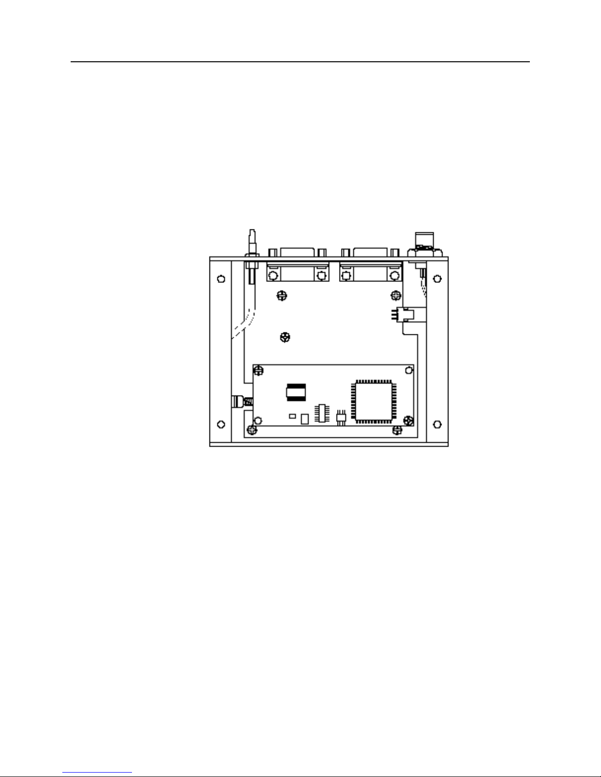
1.2 GPS Receiver Module
In the Starter Kit, the Lassen-SK8 is installed on an interface motherboard which is
housed in a metal enclosure (see Figure 1-1). This packaging simplifies testing and
evaluation of the module by providing an RS-232 serial interface which is compatible with
most PC communication ports, and by providing a DC power supply which converts a 9 to
32 volts DC input to the regulated 5 volts required by the module. The DB9 connectors
provide an easy connection to the PC's serial port using the interface cable provided in the
kit. The metal enclosure protects the module and motherboard for testing outside of the
laboratory environment.
Starter Kit
Figure 1-1. The Module Installed Inside the Interface Unit
Lassen-SK8 Embedded GPS Module 1-5
Page 28
Starter Kit
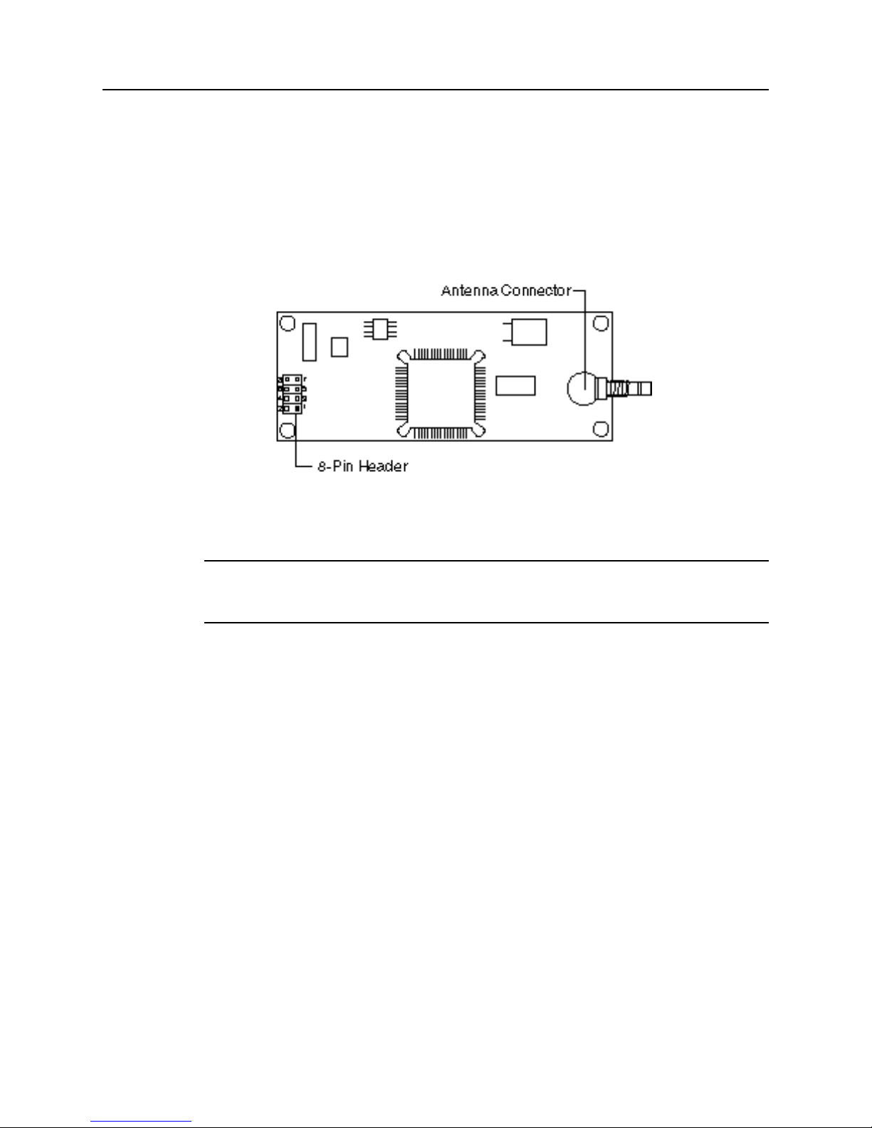
The receiver module (see Figure 1-2) consists of a single 3.25" x 1.25" x 0.40" module. A
standard SMB RF connector (J1) supports the GPS antenna connection. The center
conductor supplies +5 VDC for the Low Noise Amplifier of the active antenna. An 8-pin,
0.1 inch header (J4) supports the serial interface (CMOS TTL level), the pulse-per-second
(PPS) signal (CMOS TTL level), and the input power (+5 VDC). This module connects to
the motherboard via the 8-pin header and is secured by two standoffs. An RF-interface
cable connects the antenna port to an SMB connector on the enclosure panel.
*
Figure 1-2. Receiver Module
Note – The receiver included in the Starter Kit contains a socket for the firmware ROM.
This socketed board may be used to evaluate future releases of firmware. The standard
OEM module is not equipped with a socket.
1-6 Lassen-SK8 Embedded GPS Module
Page 29
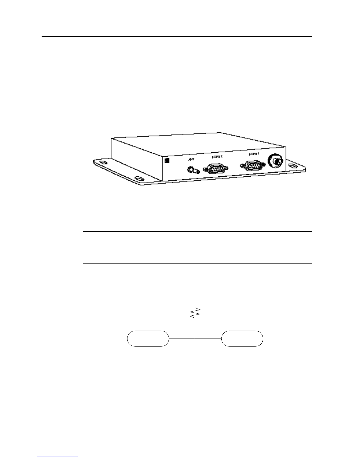
Starter Kit
The interface motherboard includes a 9 to 32 VDC switching power supply which
provides a regulated +5 VDC to the receiver. It also converts the TTL-level I/O to RS-232
for a direct interface to a computer. The motherboard provides an open-collector interface
for the PPS and also includes a 3.6V lithium backup battery enabling lightening-fast hot
starts. The Starter Kit includes an AC/DC converter for powering the module from an AC
wall socket. The metal enclosure (see Figure 1-3) provides 2 interface port connectors, an
antenna connector and a power connector. The mounting plate is secured to the metal
enclosure with four screws. The eight pin header plugs into the corresponding 8-pin socket
on the motherboard as shown in Figure 1-3.
*
Figure 1-3. Starter Kit Interface Unit
Note – Due to the open-collector interface, the polarity of the PPS signal is inverted. The
pulse is a 10µs negative-going pulse with the falling edge synchronized to UTC. When
removed from the motherboard, the receiver provides a TTL level, positive-going pulse. In
order to pull up the 1pps use a 10k pull up resister as shown in the following illustration.
.
+5Vdc
10K ohm
PORT 1
Pin 9
Figure 1-4. Open Collector PPS
The Starter Kit interface unit provides fifty percent of the duty cycle on the PPS line.
•
PPS
Pin 9
Lassen-SK8 Embedded GPS Module 1-7
Page 30
Starter Kit
1.3 Antenna
The GPS antenna receives the GPS satellite signals and passes them to the receiver.
Because the GPS signals are spread spectrum signals in the 1575 MHz range and do not
penetrate conductive or opaque surfaces, the GPS antenna must be located outdoors with a
clear view of the sky. The Lassen-SK8 requires an active antenna. The received GPS
signals are very low power, approximately -140 dB, at the surface of the earth. Trimble's
active antennas include a preamplifier that filters and amplifies the GPS signals before
delivery to the receiver.
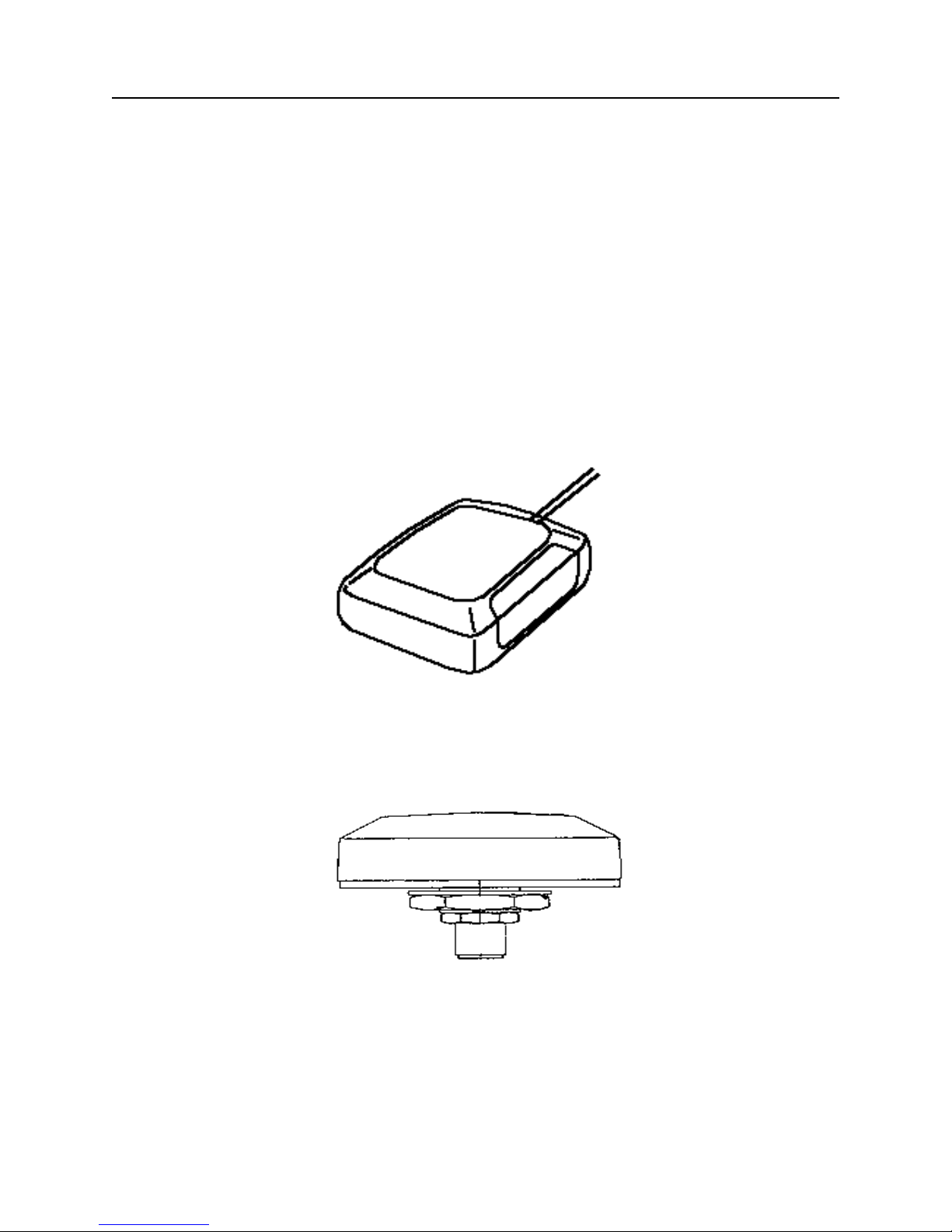
Trimble offers a variety of antennas for use with the Lassen-SK8. The compact magnetic
mount GPS antenna and integral cable supplied with the Starter Kit is ideal for portable
and mobile applications. A permanent, bulkhead mount antenna is also available. A
compact, pole-mount rooftop antenna is available for fixed-site installations. Refer to
Appendix F for mechanical outline drawings of the GPS antennas.
Figure 1-5. Magnetic Mount GPS Antenna
Figure 1-6. Hard Mount GPS Antenna
1-8 Lassen-SK8 Embedded GPS Module
Page 31

1.4 Power
Starter Kit
Figure 1-7. Bullet II GPS Antenna
The receiver module is designed for embedded applications and requires a regulated +5.0
VDC input (+4.75 to +5.25 VDC). See Power Requirements in Chapter 4 for detailed
specifications. In the Starter Kit, the motherboard includes a DC power regulator which
converts a 9 to 32 VDC input to the regulated 5 VDC required by the module. Power can
be applied to the Starter Kit module using one of two options: the DC power cable (see
Figure 1-8) or the AC/DC power converter (see Figure 1-9).
Figure 1-8. DC Power Cable
The DC power cable is ideal for bench-top or automotive testing environments. The power
cable is terminated at one end with a 3-pin plastic connector which mates with the power
connector on the metal enclosure. The unterminated end of the cable provides easy
connection to a DC power supply. Connect the red power lead to a source of DC positive
+9 to +32 VDC, and connect the black power lead to ground. This connection supplies
power to both the receiver module and the antenna. The combined power consumption of
the receiver module and the antenna is 200 milli-amps.
Lassen-SK8 Embedded GPS Module 1-9
Page 32

Starter Kit
*
Note – The yellow wire is not used in the Starter Kit. Battery back-up is provided by a
factory installed 3.6V lithium battery on the motherboard.
The AC/DC power converter may be used as an alternate power source for the Starter Kit
module. The AC/DC power converter converts 110 or 220 VAC to a regulated 12 VDC
compatible with the Starter Kit module. The AC/DC power converter output cable is
terminated with a 3-pin connector compatible with the power connector on the metal
enclosure. The AC power cable is not provided in the kit, since this cable is countryspecific. The input connector is a standard 3-prong connector used on many desktop PCs.
Figure 1-9. AC/DC Power Converter
1.5 Hardware Setup
The Lassen-SK8 supports TSIP, TAIP, and NMEA protocols. Port 1 is used for TSIP or
TAIP I/O and port 2 is used to input RTCM corrections and output NMEA messages.
Follow the steps below to setup the Starter Kit. Figure 1-10 illustrates the setup.
1. For TSIP or TAIP Protocols, connect one end of the 9-pin serial interface cable to
Port 1 (or Port 2 to view NMEA data) of the receiver module. Connect the other
end of the cable to COM1 or COM2 on a PC. A 9-pin-to-25-pin adapter may be
required for the serial interface connection to a PC, if your PC has a 25-pin
communication port.
2. Connect the antenna cable to the interface unit. This connection is made by
pushing the antenna cable connector onto the SMB connector on the unit (to
remove the antenna cable, simply pull the antenna connector off of the SMB
connector). Place the antenna so that it has a clear view of the sky.
3. Using either the DC power cable or AC/DC power converter, connect to the 3-pin
power connector on the interface unit.
- DC Power Cable — Connect the terminated end of the power cable to the
power connector on the interface unit. Connect the red lead to DC positive
voltage (+9 to +32 VDC) and black power lead to DC ground. The yellow
wire is not used. Switch on the DC power source.
1-10 Lassen-SK8 Embedded GPS Module
Page 33

Starter Kit
Power Converter
Electrical
- AC/DC Power Converter — Connect the output cable of the converter to the
3-pin power connector on the interface unit. Using the appropriate 3-prong
AC power cable (not provided), connect the converter to an AC wall socket
(110 VAC or 220 VAC). The AC power cable is not provided in the Starter
Kit.
Antenna
Figure 1-10. Interconnect Diagram
1.6 Running the TSIP Interface Program
The Starter Kit includes a disk containing TSIP interface programs which run on a PCDOS platform. These programs aid system integrators in monitoring the receiver module's
performance and in developing the software interface for the GPS module. The TSIP
programs are described in detail in Appendix B, TSIP User's Guide.
1. Connect one end of the serial interface cable to Port 1 of the Starter Kit interface
unit. Connect the other end of the cable to COM1 or COM 2 of your PC.
2. Turn on the DC power source or plug in the AC/DC converter.
3. Turn on the PC.
4. Insert the GPS Tool Kit disk in the disk drive.
5. Go to the directory where you wish to establish the GPS tool kit sub directory. In
most cases, this will be the root directory on the C: drive.
*
Note – For detailed installation guidelines, read the install text file A:\README.TXT. The
toolkit disk contains a self-extracting zip file that installs the program onto your DOS
computer.
Lassen-SK8 Embedded GPS Module 1-11
Page 34

Starter Kit
6. At the DOS prompt, type A:\INSTALL. The executable program creates a sub
directory called TOOLKIT and installs the tool kit files.
7. Type the appropriate path name to execute the TSIPCHAT program (e.g.
C:\TOOLKIT\TSIPCHAT). TSIPCHAT provides full access to the TSIP protocol. It
converts binary TSIP packets into printable ASCII characters and vice versa.
When TSIPCHAT is initiated, it configures the PC serial port to the default TSIP
settings (9600 baud, 8-Odd-1).
8. After the TSIPCHAT title screen appears, press [?], and the primary TSIPCHAT
screen shown in Figure 1-11 is displayed.
9. To test the connection, press [V]. This message requests the firmware version
numbers from the GPS module. If connected and operating properly, the module
should respond with a software version report within one second. This report will
be displayed in the command window.
When a GPS antenna is connected to a receiver and has achieved a position fix, the
transmitted position reports scroll through the report window (see Figure 1-11). These
reports include position, velocity and other GPS information. A receiver health report is
sent every few seconds, even when no satellites are being tracked.
Figure 1-11. TSIPCHAT Command Window and Report Window
The upper (shaded) portion of the screen is the command/response window and the lower
portion of the screen is the automatic report window (auto window). The auto window
displays a running account of the messages which are automatically output by the GPS
module in the lower half of the screen. The most common reports are the position and
velocity reports. Other automatic reports include receiver status and health information.
1-12 Lassen-SK8 Embedded GPS Module
Page 35

Starter Kit
When the GPS module has completed a position fix and starts transmitting position
reports, the position reports will begin scrolling in the auto window. An automatic receiver
health report is sent every few seconds, even when no satellites are being tracked.
If the auto window is not displaying messages, then the GPS module may not be
connected properly to the computer. To test the connection, press [V].
If the message, WAITING FOR REPLY appears continuously in the command window,
then the GPS module is not communicating with the computer. If this occurs, re-check the
interface cable connections and verify the serial port selection. If the communication
failure still occurs after checking all connections and settings, please call the Trimble
Technical Assistance Center (TAC) for assistance.
Lassen-SK8 Embedded GPS Module 1-13
Page 36

Starter Kit
1-14 Lassen-SK8 Embedded GPS Module
Page 37

2 Hardware Integration
The integration of the Lassen-SK8 receiver module is discussed in two sections: Hardware
Integration and Software Interface. This chapter, Hardware Integration, includes
instructions for mounting the GPS module and physically connecting the module to the
antenna, the host processor, and the power source. Chapter 3, Software Interface, provides
guidelines for configuring the Lassen-SK8 receiver module to communicate with the host
processor.
2.1 The Lassen-SK8 Receiver Module
In the Starter Kit, the Lassen-SK8 receiver module is installed on the interface
motherboard to facilitate testing and evaluation. The receiver module can be detached
from the motherboard for installation into a specific device.
The receiver module is connected to the motherboard at four points: the antenna
connector, the interface connector, and two standoffs (see Figure 2-1). Follow the steps
below to remove the receiver module from the motherboard.
Figure 2-1. Motherboard Connection Points
Lassen-SK8 Embedded GPS Module 2-1
Page 38

Hardware Integration
I
Caution – Before disassembling the interface unit, disconnect the unit from any external
power source and confirm that both you and your work surface are properly grounded for
ESD protection. The interface unit motherboard contains a 3.6V lithium battery. Exercise
caution when removing it from the Lassen-SK8 unit.
1. Remove the four screws which secure the bottom plate to the base of the metal
enclosure. Set the bottom plate aside.
2. Remove the two screws securing the Lassen-SK8 module to the standoffs on the
motherboard. These screws are located at opposite ends of the receiver module
(see Figure 2-2)
Figure 2-2. Removing the Receiver Module
*
3. Carefully pull the module straight off the motherboard to disengage the 8-pin
header from the 10-pin socket on the motherboard (see Figure 2-2). Do not rotate
or flex the module while disengaging the header, since this could damage the
connector or the board components. Pull straight up, keeping the Lassen-SK8
parallel to the motherboard.
4. Disconnect the RF cable connecting the Lassen-SK8 module to the SMB
connector on the enclosure. This connection was made by pushing the antenna
cable connector onto the SMB connector on the receiver. To remove the antenna
cable, grasp the cable connector and pull it straight off of the antenna connector.
Do not twist the cable or attempt to pull it off at an angle, as this may damage the
connector.
5. To reinstall the Lassen-SK8 board in the motherboard, follow steps 1 - 4 in
reverse order.
Note – The Lassen-SK8 is designed for embedded applications. The digital I/O lines and
power lines are not designed with additional ESD protection as a stand-alone module
would be. Use standard CMOS ESD handling precautions when removing and installing
the receiver module.
2-2 Lassen-SK8 Embedded GPS Module
Page 39

2.2 Interface Connector
The Lassen-SK8 power and data I/O functions are integrated into a single 8-pin header
connector, J4. The J4 connector uses 0.025 inch pins on 0.10 inch spacing (refer to the
mechanical outline drawing in Appendix F).
Table 2-1. I/O Connector Signals
Pin # Function Description
1 TXD 2 Port 2 transmit, CMOS/TTL
2 Prime Power 5VDC ±5%, 150 mA typical
3 TXD 1 Port 1 transmit, CMOS/TTL
4 Backup Power +3.2VDC to +5.25VDC, 2uA typical
5 RXD 1 Port 1 receive, CMOS/TTL
6 1 PPS Pulse-Per-Second, CMOS/TTL
7 RXD 2 Port 2 receive, CMOS/TTL
8 GND Ground, Power and Signal
Pins 3 and 5 on J4 are also referred to as the primary serial port. Pins 1 and 7 are also
referred to as the secondary serial port.
Hardware Integration
1
2
3
4
5
5
5
6
7
8
Figure 2-3. Interface Connector Pin Identification
2.3 Power Requirement
The Lassen-SK8 receiver module requires +5 volts DC ±5% at 150 mA, typically
excluding the antenna. For power-on surge design considerations, the prime power should
be able to source up to a maximum load of 200 mA. The on-board capacitance on prime
power is 10 µF. An important design consideration for power is the receiver module's
internal clock frequency at 12.504 MHz ± 3 KHz. Interference spurs on prime power in
this narrow frequency band should be kept to less than 1mV.
Lassen-SK8 Embedded GPS Module 2-3
Page 40

Hardware Integration
The receiver does not require any special power up or down sequencing. The receiver
power is supplied through pin 2 of the I/O connector. Refer to Table 2-2 for the +5 VDC
power specifications.
The Lassen-SK8 module provides an input for battery back-up (BBU) power to keep the
module's RAM memory alive and to power the real-time clock when the receiver's prime
power is turned off. RAM memory is used to store the GPS almanac, ephemeris, and last
position. User configuration data, including port parameters and receiver processing
options, are stored in non-volatile EEROM which does not require back-up power. By
using battery back-up, time to first fix is reduced to 20 seconds (typical). Though not
required, providing BBU power can reduce power-on time. A 3.6 volt lithium battery used
for back-up power can last up to five years.
*
*
Note – 3.2V is the minimum allowable voltage. When the power output drops below 3.2V,
the real-time clock may not operate over the specified full temperature range.
Table 2-2. Power Requirements
Signal Voltage Current J4 Pin
VCC +4.75 to +5.25 200 mA 2
Battery Backup +3.2 to +5.25 0uA with prime power; 2uA
@ 3.5V, 25°C without prime
power
Ground 0 - 8
The Lassen-SK8 receiver module will maintain full performance specification when the
prime power line is coupled with less than 100 mV of ripple noise, peak to peak from 1Hz
to 1MHz.
Note – The Lassen-SK8 Starter Kit motherboard contains a 3.6V lithium battery.
4
2.4 Serial Interface
As an embedded design, the Lassen-SK8 receiver module provides direct CMOS
compatible TTL level serial I/O. The RX and TX signals on the J4 I/O connector are
driven directly by the DUART on the Lassen-SK8. Interfacing these signals directly to a
DUART in your application circuitry provides direct serial communication without the
complication of RS-232 or RS-422 line drivers.
*
2-4 Lassen-SK8 Embedded GPS Module
Note – The serial I/O signals on J4 are TTL level. They are not inverted or driven to RS232 levels.
Page 41

2.5 Pulse Per Second
A ten microsecond wide, CMOS compatible TTL level pulse is available on pin 6 of the J4
I/O connector. This pulse is issued once per second with the rising edge of the pulse
synchronized with UTC. The pulse will be shaped by the distributed impedance of the
attached signal line and input circuit. The rising edge is typically less than 20 nSec. The
falling edge should not be used.
The timing accuracy is ± 100 nanosecond (1Σ) and is available only when valid position
fixes are being reported. Repeatability checks of 10 sets of 100 one second samples taken
over a period of 20 minutes showed an average variation of approximately 100
nanoseconds (not allowing for SA).
2.6 Mounting
The Lassen-SK8 provides four 0.125 inch mounting holes that will accept 3/16 inch round
or hex standoffs with 3/8 inch height, and #4 or M3 mounting screws. Space constrained
environments may require a different stand-off. Refer to the mechanical outline drawing
in Appendix F for dimensions and clearances.
Hardware Integration
2.7 RF Shield
An optional RF shield is available for production versions of the standard temperature
Lassen-SK8 module. The production versions of the Lassen-SK8 do not have a socketed
EPROM. This RF shield protects the GPS module from interference with other electronics
and also makes the module compliant with the CE emission specification. The RF shield is
not compatible with the socketed board provided in the Starter Kit nor with the extended
temperature board that has a TCXO oscillator.
*
Note – Many installations do not require the optional shield. The Lassen-SK8 is designed
to be immune to most interference.
Lassen-SK8 Embedded GPS Module 2-5
Page 42

Hardware Integration
2-6 Lassen-SK8 Embedded GPS Module
Page 43

3 Software Interface
This chapter describes the Lassen-SK8 software interface, the start-up characteristics for
the interface protocols, a description of the receiver operating modes, and a brief
discussion of the interface protocols.
3.1 Start-up
ACE GPS is a complete 8-channel parallel tracking GPS receiver designed to operate with
the L1 frequency, standard position service, Coarse Acquisition code. Using two highly
integrated Trimble custom integrated circuits, the receiver is designed in a modular format
especially suited for embedded applications.
When connected to an external GPS antenna, the receiver contains all the circuitry
necessary to automatically acquire GPS satellite signals, track up to 8 GPS satellites, and
compute location, speed, heading, and time. The receiver will automatically begin to
search for and track GPS satellite signals at power-up.
The performance of a GPS receiver at power-on is determined largely by the availability
and accuracy of the satellite ephemeris data and the availability of a GPS system almanac.
Refer to Chapter 4 for additional information. The first time the receiver is powered-up, it
is searching for satellites from a cold start (no almanac). While the receiver will begin to
compute position solutions within the first two minutes, it actually takes the receiver about
15 minutes to download a complete almanac. This initialization process should not be
interrupted. With a complete almanac and back-up power, the time to first fix can typically
be shortened to less than 20 seconds. The receiver will respond to commands almost
immediately after power-up.
3.2 Software Tool Kits
Trimble provides a Software Developers Tool Kit to support the TSIP and TAIP
protocols. The Kit contains a user-friendly program to communicate with the receiver and
includes sample C source code and reusable routines to aid in developing applications.
The following Appendices provide additional information:
• TSIP
- Appendix A, Trimble Standard Interface Protocol
- Appendix B, TSIP User's Guide
• TAIP
- Appendix D, GPSSK User's Guide (TAIP)
- Appendix E, NMEA 0183.
Lassen-SK8 Embedded GPS Module 3-1
Page 44

Software Interface
3.3 Communicating with the Lassen-SK8 Module
The Lassen-SK8 supports three I/O message protocols: TSIP, TAIP, and NMEA. The
protocols are discussed at the end of this chapter, and are explained in detail in
Appendices A through E.
Communication with the Lassen-SK8 module is through two CMOS compatible, TTL
level serial ports. The port characteristics can be changed to accommodate your
application requirements. Port parameters are stored in a non-volatile electrically erasable
ROM (EEROM) that does not require backup power. Table 3-1 lists the default
characteristics for each port.
Table 3-1. Default Serial Port Characteristics
Input
Port
1 TAIP Baud Rate: 4800
1 TSIP Baud Rate: 9600
2 RTCM Baud Rate: 4800
Protocol Default Setup
Data Bits: 8
Parity: Odd
Stop Bits: 1
No Flow Control
Data Bits: 8
Parity: Odd
Stop Bits: 1
No Flow Control
Data Bits: 8
Parity: None
Stop Bits: 1
No Flow Control
Output
Language Default Setup
TAIP Baud Rate: 4800
Data Bits: 8
Parity: Odd
Stop Bits: 1
No Flow Control
TSIP Baud Rate: 9600
Data Bits: 8
Parity: Odd
Stop Bits: 1
No Flow Control
NMEA Baud Rate: 4800
Data Bits: 8
Parity: None
Stop Bits: 1
No Flow Control
Any standard serial communications program, such as Windows Terminal or
PROCOMM, can be used with the TAIP or NMEA interface protocol. TSIP is a binary
protocol and outputs raw serial data onto the screen which cannot be read. Trimble
encourages the use of the DOS compatible software tool kit provided for TSIP. The serial
port drivers in the Trimble tool kit, TSIPCHAT, match the Lassen-SK8 serial port
characteristics. The TSIPPRNT program converts binary data logged with the TSIPCHAT
program into ASCII characters that may be printed and displayed.
M
3-2 Lassen-SK8 Embedded GPS Module
Warning – When using the TSIP protocol to change port assignments or characteristics,
confirm that your changes do not affect the ability to communicate with the receiver
module.
Page 45

3.4 Protocol Summary
The Lassen-SK8 receiver is shipped from the factory with the following configuration:
• TSIP
- 9600 baud 8-odd-1 on Port 1
• NMEA out/RTCM in
- 4800 baud 8-none-1 on Port 2
The receiver can easily be reconfigured for other combinations of language and port baud
rate and parity. These settings are kept in BBRAM (Battery Backed Random Access
Memory) and can be saved into non-volatile memory if desired. The commands include:
• TSIP command: 0xBC
• TAIP command: PT
Refer to Appendix A.3, Customizing Receiver Operations, for additional information on
protocols.
If the receiver is not talking to application programs, the ports may be configured to an
unknown setting. Use the following Toolkit program commands to return the receiver to
the factory default setting:
Software Interface
• TSIP: SK8BREAK
• TAIP: SK8TAIP
3.4.1 TSIP Data Output
The Trimble Standard Interface Protocol (TSIP) is the native language for the LassenSK8. TSIP is a binary language, with a wide variety of commands and reports. TSIP
reports can be output automatically, or they can be output as responses to queries. The
format of the automatic reports can be easily configured. Refer to Appendix A.3,
Customizing Receiver Operations and Appendix A.4, Automatic Position and Velocity
Reports for further information. The receiver is shipped from the factory configured for
single precision Latitude-Longitude-Altitude. Customized position and velocity formats
can be created by using the information in Appendix A.3, Customizing Receiver
Operations.
The TSIPCHAT program in the Lassen-SK8 Starter Kit permits using a computer keyboard
to send the Request Packets to the GPS receiver. The responses to these requests are then
displayed on a DOS computer screen in ASCII format. C source code routines for the
TSIPCHAT program are also provided in the Starter Kit. C source can be used as a
software design guide by programmers who need to communicate system integration
information with the Lassen-SK8.
Lassen-SK8 Embedded GPS Module 3-3
Page 46

Software Interface
Configuring the ACE GPS receiver output protocol from TSIP to TAIP
protocol.
TSIP command packet 0xBC can be configured in accordance with the following
procedure:
1. Run TSIPCHAT -Cx (Where x = Host Computer COM Port).
2. Once TSIPCHAT is running:
a. Press [?]. The following will be displayed:
Keystroke Command List
3. Initiate the 0xBC Command Packet. Refer to Packet BC in the Appendix A,
Trimble Standard Interface Protocol for further information.
a. Press [U]
b. Press the [SPACE{BAR] to cycle through the options. Enter the following:
c. Set (1)
d. Press [Enter]
4. Select the Port to be configured: Do the following:
a. Press the [SPACE{BAR] to cycle through the options
b. Select Port 1 (0)
c. Press [Enter]
5. Set the Receiver Port configuration Input Baud rate:
a. Press the [SPACE{BAR] to cycle through the options
b. Make a selection
c. Press [Enter]
6. Set the Receiver Port configuration Output Baud Rate:
a. Cycle through the options by pressing the [SPACE{BAR]
b. Select the Output Baud Rate
c. Press [Enter]
7. Set the Data Bits.
a. Select the appropriate Data Bits. TAIP is the default: TAIP =8.
b. Press [Enter]
8. Set Parity.
a. Select the appropriate Parity. TAIP is the default: TAIP =Odd.
b. Press[Enter]
9. Set Stop Bits.X
a. Select the appropriate Stop Bits. TAIP is the default: TAIP =8:
b. Press [Enter]
3-4 Lassen-SK8 Embedded GPS Module
Page 47

Software Interface
10. Set the Flow Control
a. Press the [SPACE{BAR] to cycle through the options
b. Select the appropriate Flow Control. TAIP is the default: TAIP =Off
c. Press[Enter]
11. Set Protocol In:
a. Press the [SPACE{BAR] to cycle through the options
b. Select TAIP (0)
c. Press [Enter]
12. Set Protocol Out:
a. Press the [SPACE{BAR] to cycle through the options
b. Select TAIP (0)
c. Press [Enter]
13. If satisfied with these selections:
a. Press [Y] — Saves the configuration
b. Press [N] — Aborts the configuration and displays the message: ABORTED
3.4.2 TAIP Data Output
The Trimble ASCII Interface Protocol (TAIP) is a Trimble-specified digital
communication interface based on printable ASCII characters over a serial data link. TAIP
interface provides the means to configure the Lassen-SK8 receiver to output various
sentences in response to query or on a scheduled basis. TAIP messages may be scheduled
for output at a user specified rate starting on a given epoch from top of the hour. For
communication robustness, the protocol optionally supports checksums on all messages. It
also provides the user with the option of tagging all messages with the unit's user specified
identification number (ID). This greatly enhances the functional capability of the unit in a
network environment. This protocol is described in Appendix C, Trimble ASCII
Interface Protocol (TAIP).
The receiver can easily be configured to TAIP with the program SK8TAIP contained in
the Toolkit. This program re-configures the Lassen-SK8 to Default TAIP settings: TAIP at
4800 8-none-1 on Port 1, RTCM in / silent out at 4800 8-none-1 on Port 2. The program
stores these settings, along with all the other defaults, to non-volatile memory. The
GPSSK program can now be used to control and re-configure the receiver.
Receiver configurations created in GPSSK can be stored in non-volatile memory using the
RT command. As mentioned above, the receiver ports can also be set to TAIP through a
TSIP port using TSIPCHAT and the TSIP command 0xBC.
Lassen-SK8 Embedded GPS Module 3-5
Page 48

Software Interface
Configuring the ACE GPS receiver output protocol from TAIP to TSIP
protocol TAIP message PR
Configuring the receiver output from TAIP to TSIP will display binary data in now
displayed on the screen.
Where:
Table 3-2. TSIP Message Description
1. Run GPSSK /x. Press [x] to select the Host Computer COM Port
2. When the GPS Main screen appears, press [ENTER]
3. Type the following message to set the receiver to TSIP.
>SPR;TAIP=FF;TSIP=TF;<
ELEMENT DESCRIPTION
> Beginning of command sentence
S The Set Command
PR The TAIP protocol message
TSIP The desired protocol
FF Port 1 off
Port 2 off
TF Port 1 in /out
Port 2 off
I/O Port 1 in
Port 2 output
< End of command sentence
4. Press [ENTER] to complete the change
Use TSIPCHAT to make additional changes.
3.4.3 NMEA 0183 Data Output
The National Marine Electronics Association (NMEA) protocol is an industry standard
data protocol which was developed for the marine industry. Trimble has chosen to adhere
stringently to the NMEA 0183 data specification as published by the NMEA. Although
the Trimble Lassen-SK8 supports seven NMEA sentences that contain GPS information,
the standard Lassen-SK8 only outputs the GGA and VTG data strings.
*
3-6 Lassen-SK8 Embedded GPS Module
Note – Contact your Trimble sales representative if you need access to all or a subset of
the other five NMEA sentences.
Page 49

NMEA data is output in standard ASCII sentence formats. Message identifiers are used to
signify what data is contained in each sentence. Data fields are separated by commas
within the NMEA sentence. In the Lassen-SK8, NMEA is an output only protocol. The
NMEA protocol is described in detail in Appendix E, NMEA 0183.
The receiver is shipped from the factory with NMEA output on Port 2. Port 2 settings can
be changed using TSIPCHAT and command 0xBC. TSIP command 0x7A changes the
NMEA output sentences and output rates. The new settings are saved to BBRAM or they
can be saved to non-volatile memory using TSIP command 0x8E-26.
3.5 Timing Applications
The Lassen-SK8 is an excellent source for accurate system timing. Examples of
applications requiring accurate time are environmental data acquisition or synchronization
of communications networks. The timing functions of the receiver are supported by the
TSIP protocol. See Report Packet 41 in Appendix A for a description of the time function
reports for TSIP.
Software Interface
*
Note – Note that GPS time differs from UTC (Universal Coordinated Time) by a variable
integer number of seconds: UTC = (GPS time) - (GPS UTC Offset)
As of July 1997, the GPS UTC offset was 12 seconds. The offset increases by 1 second
approximately every 18 months. System designers should plan to read the offset value as a
part of the timing interface to obtain UTC. The GPS week number is in reference to a base
week (Week #0), starting January 6, 1980.
The current GPUSTC offset is contained within the almanac transmitted by the GPS
system. The Lassen-SK8 must have a complete almanac before the offset data is valid.
3.5.1 Effect of GPS Week Number Roll-over (WNRO)
At 0000 hours Greenwich Mean Time (GMT) on 21/22 August 1999, the GPS Week
Number will roll-over from 1023 to zero. Trimble receivers have numerous built-in
protections to prevent this from being a catastrophic event. Systems may benefit however,
from extra care with the first power-up after WNRO.
*
Note – GPS Week Numbers occupy a range from zero to 1023 such that the Week
Number Roll Over (WNRO) occurs every 1024 weeks, or approximately every 19 years 8
months. August 1999 is the first roll-over for the GPS system since the beginning of GPS
time on 06 January 1980.
Lassen-SK8 Embedded GPS Module 3-7
Page 50

Software Interface
The following two known issues for previous versions of receivers exist as a result of
testing a representative sample of Trimble OEM receivers.
There is no impact for TSIP users on position or time information. The reported GPS week
number will reset to zero however, and users that require this information may need to
make a software modification to accommodate this change.
ACE GPS/Palisade Family Firmware Version 7.xx Software Modifications
The Lassen-SK8 receiver has been designed to handle WNRO and there are no problems
with either dates or the first fix after WNRO through the year 2015.
• An almanac recorded prior to WNRO is not correct after WNRO. This problem
only exists when the receiver main power is OFF and battery back-up power is
ON at the moment of WNRO. Once the receiver is cold started, a post-WNRO
almanac is collected and the receivers behavior returns to normal.
• Day-month-year representations will be incorrect after WNRO when using
specific TAIP and NMEA messages. Time and day information will not be
effected however.
I
Caution – Trimble OEM GPS receivers have reported the true GPS Week Number in
TSIP messages 0x41 and 0x8F-20 as a number between 0 and 1023. The Lassen-SK8
however, outputs the Extended GPS Week Number as the absolute number of weeks
since the beginning of GPS time or 06 January 1980. If the true GPS Week Number is
desired, the system developer should ignore the extra MSBs of the Extended GPS Week
Number and use only the 10 LSBs.
3.6 Differential GPS
The Lassen-SK8 module can use differential corrections to compute a Differential GPS
position (DGPS). DGPS can provide position accuracy of 2 meters (1 sigma).
RTCM SC-104, the industry standard format for differential corrections, is available from
most DGPS reference stations, Coast Guard beacon transmissions, and commercial DGPS
subscription services. The Lassen-SK8 is fully compatible with RTCM SC-104 Version
2.1. The Lassen-SK8 is configured to accept RTCM SC-104 correction data over port 2
(J4, pin 7) at 4800 baud, 8 data bits, 1 stop bit and no parity. The DGPS operating mode is
set to Automatic which means that the receiver will provide differential GPS solutions
when valid correction data is available and will output standard GPS solutions when no
valid correction data is available.
No setup is required to use RTCM SC-104 differential corrections, however, you may
need to reconfigure the serial port characteristics (baud rate, data bits, stop bits and parity)
to match the characteristics of your RTCM SC-104 data source using the TSIP packet
BCh. See Appendix A for more information on this message. Table 3-1 summarizes the
default characteristics for the Lassen-SK8 serial ports.
3-8 Lassen-SK8 Embedded GPS Module
Page 51

Software Interface
Alternatively, you may use Trimble's TSIP packets 60h and 61h to apply differential
corrections through the Lassen-SK8 port 1 (J4, pin 5). These packets can be interleaved
with the TSIP command stream. Packets 60h and 61h are useful in applications which
require the use of a single communications channel between the Lassen-SK8 and the
system. Note that using these messages requires you to reformat the RTCM SC-104
differential correction data into the 60h/61h message format. See Appendix A for more
information on these messages.
Lassen-SK8 Embedded GPS Module 3-9
Page 52

Software Interface
3-10 Lassen-SK8 Embedded GPS Module
Page 53

4 Operation and Performance
This chapter describes the Lassen-SK8 satellite acquisition and tracking processes,
performance characteristics and system architecture. This discussion assumes that you are
familiar with the basic theory of the Global Positioning System. Before proceeding to the
detailed discussion of the satellite acquisition and tracking process, please review the GPS
satellite message description on the next page.
The Lassen-SK8 satellite acquisition and tracking algorithms can achieve a position
solution without any initialization. The receiver automatically selects and tracks the best
combination of satellites to compute position and velocity. As satellites move out of view,
the Lassen-SK8 automatically acquires new satellites and includes them in the solution set
as required.
4.1 GPS Satellite Message
Every GPS satellite transmits the Coarse/Acquisition (C/A) code and satellite data
modulated onto the L1 carrier frequency (1575.42 MHz). The satellite data transmitted by
each satellite includes a satellite almanac for the entire GPS system, its own satellite
ephemeris and its own clock correction.
The satellite data is transmitted in 30-second frames. Each frame contains the clock
correction and ephemeris for that specific satellite, and two pages of the 50-page GPS
system almanac. The almanac is repeated every 12.5 minutes. The ephemeris is repeated
every 30 seconds.
The system almanac contains information about each of the satellites in the constellation,
ionospheric data, and special system messages. The GPS system almanac is updated
weekly and is typically valid for months. The ephemeris contains detailed orbital
information for a specific satellite. Ephemeris data changes hourly, but is valid for up to
four hours. The GPS control segment updates the system almanac weekly and the
ephemeris hourly through three ground-based control stations. During normal operation,
the Lassen-SK8 module updates its ephemeris and almanac as needed.
The performance of a GPS receiver at power-on is determined largely by the availability
and accuracy of the satellite ephemeris data and the availability of a GPS system almanac.
Lassen-SK8 Embedded GPS Module 4-1
Page 54

Operation and Performance
4.2 Satellite Acquisition and Time to First Fix
4.2.1 Cold-Start
The term “cold-start” describes the performance of a GPS receiver at power-on when no
navigation data is available. “Cold” signifies that the receiver does not have a current
almanac, satellite ephemeris, initial position, or time. The cold-start search algorithm
applies to a Lassen-SK8 which has no memory of its previous session (i.e., is powered on
without the memory backup circuit connected to a source of DC power). This is the “out
of the box” condition of the GPS module as received from the factory.
In a cold-start condition the receiver automatically selects a set of eight satellites and
dedicates an individual tracking channel to each satellite, to search the Doppler range
frequency for each satellite in the set. If none of the eight selected satellites is acquired
after a pre-determined period of time (time-out), the receiver will select a new search set
of eight satellites and will repeat the process, until the first satellite is acquired. As
satellites are acquired, the receiver automatically collects ephemeris and almanac data.
The Lassen-SK8 uses the knowledge gained from acquiring a specific satellite to eliminate
other satellites, those below the horizon, from the search set. This strategy speeds the
acquisition of additional satellites required to achieve the first position fix.
The cold-start search sets are established to ensure that at least three satellites are acquired
within the first two time-out periods. As soon as three satellites are found, the receiver will
compute an initial position fix. The typical time to first fix is less than 2 minutes.
A complete system almanac is not required to achieve a first position fix. However, the
availability and accuracy of the satellite ephemeris data and the availability of a GPS
almanac can substantially shorten the time to first fix.
*
Note – When installed in the interface unit, the Lassen-SK8 receives back-up power from
a lithium battery. This battery enables the Lassen-SK8 to always start from either a warm
or hot start. To force a cold start, issue the 1E TSIP command ([Control] + [K] in the TSIP
chat program on the GPS toolkit diskette in the Starter Kit).
4.2.2 Warm Start
In a warm start condition, the receiver has been powered down for a period of 1-6 hours
but has a current almanac and an initial position and time stored in memory.
When connected to an external backup battery and power is applied, the Lassen-SK8
retains the almanac, approximate position, and time to aid in satellite acquisition and
reduce the time to first fix. When an external back-up battery is not used, the TSIP
protocol allows the almanac, an initial position, and time to be uploaded to the receiver via
the serial port, to initiate a warm start.
During a warm start, the Lassen-SK8 identifies the satellites which are expected to be in
view, given the system almanac, the initial position and the approximate time. The
receiver calculates the elevation and expected Doppler shift for each satellite in this
expected set and directs the eight tracking channels in a parallel search for these satellites.
4-2 Lassen-SK8 Embedded GPS Module
Page 55

The warm start time to first fix, when the receiver has been powered down for more than
60 minutes (i.e. the ephemeris data is old) is usually less than 45 seconds.
4.2.3 Garage Search Strategy
During a warm start search, the Lassen-SK8 knows which satellites to search for, based on
the system almanac, the initial position (last known position) and the current time. In some
cases, the receiver may not be able to acquire the expected satellite signals (e.g. a vehicle
parked in a garage or a vessel in a covered berth). Trimble's patented “garage search”
strategy, also known as a split search, is designed for such situations.
If the receiver does not acquire the expected set of satellites within 5 minutes of power-on,
some of the eight tracking channels will continue to search for the expected satellites
(warm search) while the remaining channels are directed in a cold start search. This
strategy minimizes the time to first fix in cases where the stored almanac, position and
time are invalid. The stored information is flushed from memory, if the cold start search
proves effective and the warm search fails.
4.2.4 Hot Start
Operation and Performance
A hot start strategy applies when the Lassen-SK8 has been powered down for less than 60
minutes, and the almanac, position, ephemeris, and time are valid. The hot start search
strategy is similar to a warm start, but since the ephemeris data in memory is considered
current and valid, the acquisition time is typically less than 20 seconds.
4.3 Satellite Mask Settings
Once the Lassen-SK8 has acquired and locked onto a set of satellites, which pass the mask
criteria listed in this section, and has obtained a valid ephemeris for each satellite, it will
output regular position, velocity and time reports according to the protocol selected.
The default satellite masks observed by the Lassen-SK8 are listed in Table 4-1. These
masks serve as the screening criteria for satellites used in fix computations and ensure that
position solutions meet a minimum level of accuracy. The Lassen-SK8 will only output
position, course, speed and time when a satellite set can be acquired which meets all of the
mask criteria. The satellite masks can be adjusted in GPS receivers accepting the TSIP
protocol. (See the section titled Key Setup Parameters, located in Appendix A.)
Table 4-1. Default Satellite Mask Settings
Mask Setting
Elevation 5°
SNR 2
PDOP 10
PDOP Switch 5
Lassen-SK8 Embedded GPS Module 4-3
Page 56

Operation and Performance
4.3.1 Elevation Mask
Satellites below a 5° elevation are not used in the position solution. Although low
elevation satellites can contribute to a lower/better PDOP, the signals from low elevation
satellites are poorer quality, since they suffer greater tropospheric and ionospheric
distortion than the signals from higher elevation satellites. These signals travel further
through the ionospheric and tropospheric layers.
In addition, low elevation satellites can contribute to frequent constellation switches, since
the signals from these satellites are more easily obscured by buildings and terrain.
Constellation switches can cause noticeable jumps in the position output. Since worldwide
GPS satellite coverage is generally excellent, it is not usually necessary to use satellites
below a 5° elevation to improve GPS coverage time. In some applications, like urban
environments, a higher mask may be warranted to minimize the frequency of constellation
switches and the impact of reflected signals.
4.3.2 SNR Mask
Although the Lassen-SK8 is capable of tracking signals with SNRs as low as 0, the default
SNR mask is set to 3 to eliminate poor quality signals from the fix computation and
minimize constellation switching. Low SNR values may result from:
• Low Elevation Satellites
• Partially Obscured Signals (e.g. Dense Foliage)
• Multi-Reflected Signals (Multi-Path)
The distortion of signals and the frequent constellation switches associated with lowelevation satellites were discussed above. In mobile applications, the attenuation of signals
by foliage is typically a temporary condition. Since the Lassen-SK8 can maintain lock on
signals with SNRs as low as 0, it offers excellent performance when traveling through
heavy foliage.
Multi-reflected signals, also known as Multi-path, can degrade the position solution.
Multi-path is most commonly found in urban environments with many tall buildings and a
preponderance of mirrored glass, which is popular in modern architecture. Multi-reflected
signals tend to be weak (low SNR value), since each reflection attenuates the signal. By
setting the SNR mask to 2 or higher, the impact of multi-reflected signals is minimized.
4.3.3 PDOP Mask
Position Dilution of Precision (PDOP) is a measure of the error caused by the geometric
relationship of the satellites used in the position solution. Satellite sets which are tightly
clustered or aligned in the sky will have a high PDOP and will contribute to a lower
position accuracy. For most applications, a PDOP mask of 10 offers a satisfactory tradeoff between accuracy and GPS coverage time. With world-wide GPS coverage now
available, the PDOP mask can be lowered even further for many applications without
sacrificing coverage. For differential GPS applications, PDOP related error can be the
major contributor to position error. For differential GPS applications requiring the highest
level of accuracy, the PDOP mask should be set to 7 or below.
4-4 Lassen-SK8 Embedded GPS Module
Page 57

4.3.4 PDOP Switch
The default positioning mode for the Lassen-SK8 is Automatic. In this mode, the receiver
attempts to generate a 3-dimensional (3D) position solution, when four or more satellites
meeting the mask criteria are visible. If such a satellite set cannot be found, the receiver
will automatically switch to 2-dimensional (2D) mode. The PDOP switch establishes the
trade-off between 3D positioning and PDOP. With the PDOP Switch set to 6, the receiver
will compute a 2D position with a HDOP below 6 rather than a 3D position with a PDOP
greater than 6, even when four or more satellites are visible.
Operation and Performance
*
Note – PDOP Switch is only used in Auto mode. If the PDOP Switch is greater than the
PDOP Mask, it will stay in 3D mode.
4.4 Standard Operating Modes
The tracking mode controls the allocation of the receiver's tracking channels and the
method used for computing position fixes. The output of GPS data is controlled by two
operating modes:
• Fix Modes (2D, 3D, or Automatic)
• Differential GPS Mode (On, Off, or Auto)
Each of these operating modes is described below.
4.4.1 Fix Modes
The Lassen-SK8 offers three positioning modes: 2D Manual, 3D Manual, and Automatic
2D/3D. Automatic 2D/3D is the default mode for the Lassen-SK8. The positioning mode
can be modified in receivers accepting TSIP commands. See Appendix A for more
information on the TSIP protocol.
2D Manual
In 2D Manual mode, the Lassen-SK8 will only generate 2-dimensional (2D) position
solutions (latitude and longitude only), regardless of the number of visible satellites. If the
altitude is not entered, the receiver uses mean sea level as the default altitude. The greater
the deviation between the actual and default altitudes, the greater the error in the 2D
position. For TSIP applications, enter local altitude in MSL/HAE via TSIP packet 2AH
(see Appendix A).
*
Lassen-SK8 Embedded GPS Module 4-5
Note – 2D Manual mode is not recommended for differential GPS applications since any
deviation in altitude will cause a significant error in the latitude and longitude. Only use the
2D Manual mode for flat land or marine applications where the elevation is known or
constant. For DGPS applications, the 3D Manual mode is the recommended positioning
mode for the highest level of accuracy.
Page 58

Operation and Performance
3D Manual
In 3D Manual mode, the Lassen-SK8 will only generate 3-dimensional (3D) position
solutions (latitude, longitude, and altitude). A 3D solution requires at least four visible
satellites which pass the mask criteria. If less than four conforming satellites are visible,
the Lassen-SK8 will suspend position data outputs. 3D Manual mode is recommended for
differential GPS applications requiring the highest level of accuracy.
2D/3D Automatic
The default operating mode for the Lassen-SK8 is 2D/3D Automatic. In this mode, the
Lassen-SK8 attempts to generate a 3-dimensional (3D) position solution, if four or more
satellites meeting the mask criteria are visible. If only three satellites are visible which
meet the mask criteria, the Lassen-SK8 will automatically switch to 2-dimensional (2D)
mode and will use the last calculated altitude, if available, or the default altitude in the
position solution. In 2D/3D Automatic mode, the PDOP switch is active.
4.5 Differential GPS Operating Modes
The default mode for the Lassen-SK8 is DGPS Automatic. The Lassen-SK8 supports
three DGPS Modes: On, Off, and Automatic, and the mode may be changed by issuing the
appropriate TSIP command. See Appendix A for information on TSIP commands. The
three DGPS operating modes are described below.
4.5.1 DGPS On
When DGPS On is selected, the Lassen-SK8 will only provide differential GPS solutions.
If the source of correction data is interrupted or becomes invalid, the Lassen-SK8 will
suspend all output of position, course and speed data. When a valid source of correction
data is restored, the Lassen-SK8 will resume outputting corrected data.
4.5.2 DGPS Off
When DGPS Off is selected, the Lassen-SK8 will not provide differential GPS solutions,
even if a valid source of correction data is supplied. In this mode, the receiver will only
supply standard GPS data.
4.5.3 DGPS Automatic
DGPS Automatic is the default operating mode for the Lassen-SK8. In this mode, the
Lassen-SK8 will provide differential GPS solutions when valid correction data is
available. If a set of differentially correctable satellites cannot be found which meets the
satellite mask settings, the receiver will transition to output standard GPS solutions. The
Lassen-SK8 automatically switches between DGPS and standard GPS based on the
availability of valid correction data.
4-6 Lassen-SK8 Embedded GPS Module
Page 59

4.5.4 Differential GPS Operation
The Lassen-SK8 is capable of accepting and decoding RTCM SC-104 data. RTCM SC104 is an industry standard protocol for differential correction data. The Lassen-SK8 is
configured to accept RTCM SC-104 correction data over Port 2 (J4, pin 7). Alternatively,
you can use TSIP packets 60 and 61 or the TAIP and DD messages to input differential
corrections through the primary serial port (J4, pin 5).
4.6 Position Accuracy
GPS position accuracy is degraded by atmospheric distortion, satellite and receiver clock
errors, and Selective Availability (SA). Effective models for atmospheric distortion of
satellite signals have been developed to minimize the impact of tropospheric and
ionospheric effects. The impact of satellite clock errors is minimized by incorporating the
clock corrections transmitted by each satellite used in the position solution. SA is the most
significant contributor to position error and cannot be effectively combated except with
differential GPS.
4.6.1 Selective Availability (SA)
Operation and Performance
The U.S. Department of Defense, through a program called Selective Availability,
intentionally degrades GPS accuracy for civilian users. The SA program creates position
errors by modifying the apparent position of each satellite and introducing random dither
into each satellite's clock.
In extreme cases all sources of error (natural, PDOP, and SA) can combine to produce
large position errors. The DOD's definition of accuracy under SA is 100 meters 2 dRMS
(horizontal 2 dimensional, 95% of the time). In April 1996, the U.S. government approved
plans for disabling SA.
4.6.2 Differential GPS (DGPS)
Differential GPS is an effective technique for overcoming the effects of SA and other
sources of position error. DGPS relies on GPS error corrections transmitted by a reference
station placed at a known location. The reference station compares its GPS position
solution to its precisely surveyed position and calculates the error in each satellite's range
measurement. The industry standard protocol for GPS correction data is RTCM SC-104.
The GPS corrections are broadcast to mobile GPS receivers in neighboring areas. The
mobile receivers incorporate the GPS corrections in their position solution to achieve
excellent accuracy. For marine applications, corrections are typically modulated on
marine radio beacon broadcasts. For land-based applications, the correction data can be
transmitted over FM sub-carrier, cellular telephone or dedicated UHF or VHF radio links.
DGPS can reduce position error to under 5 meters, 95% of the time under steady state
conditions. The DGPS accuracy is highly dependent on the quality and age of the
differential corrections and the proximity of the mobile receiver to the reference site.
Lassen-SK8 Embedded GPS Module 4-7
Page 60

Operation and Performance
4.7 Coordinate Systems
Once the Lassen-SK8 achieves its first fix, it is ready to commence output of position,
velocity, and time information.
This information is output over serial communication channel in either the TSIP, TAIP, or
NMEA protocol, as determined by the settings of the receiver. These protocols are defined
in the following Appendices:
• TSIP - Appendix A
• TAIP - Appendix C
• NMEA - Appendix E
To change from one protocol to another, please see “Configuring your Receiver” in
Appendix A.
4.7.1 TSIP Coordinate Systems
TSIP has the widest choice of coordinate systems. The output format is chosen by TSIP
command 0x35. The output formats include the following:
• LLA position — Latitude, longitude, altitude (LLA) according to the WGS
ellipsoid or one of over a hundred other datums. See Appendix A, Table A-86 for
a list of available datums. Altitude can be chosen to be height above ellipsoid
(HAE) or height above mean sea level (MSL).
• ENU velocity — ENU velocity is the velocity in East, North, and Up coordinates.
These coordinates are easily converted to speed and heading.
• ECEF position and velocity — ECFF position and velocity is Earth-Centered,
Earth-Fixed frame is a Cartesian coordinate frame with its center at the earth's
center, the z-axis through the North Pole, and the x-axis through longitude 0
degrees, latitude 0 degrees. Velocity is reported relative to the same axes.
• UTM — Universal Transverse Mercator (UTM) is a mapping coordinate system
used by many government agencies.
There are also two time coordinate systems:
• GPS time — GPS time is determined by an ensemble of atomic clocks operated
by the Department of Defense (DOD).
• UTC time — UTC time is the world standard maintained by an ensemble of
atomic clocks operated by government organizations around the world.
GPS time is steered relative to Universal Coordinated Time (UTC). GPS does not
recognize leap seconds resulting in a situation where GPS time is currently 12 seconds
ahead of UTC time. Time tags for most output messages can be in either UTC time or GPS
time, as chosen by TSIP command 0x35.
4-8 Lassen-SK8 Embedded GPS Module
Page 61

4.7.2 NMEA 0183
The NMEA 0183 protocol only supports LLA format and UTC time. Velocity is always
described as horizontal speed and heading; vertical speed is not output.
4.7.3 TAIP
The TAIP protocol only supports LLA position output. Timetags are GPS, except for the
TM time mark message.
4.8 Performance Characteristics
4.8.1 Update Rate
The Lassen-SK8 computes and outputs position solutions once per second, on the second.
NMEA outputs can be scheduled at a slower rate using TSIP command 7Ah. Refer to
Appendix A.
Operation and Performance
4.8.2 Dynamic Limits
The dynamic operating limits for the Lassen-SK8 are listed below. These operating limits
assume that the GPS module is correctly embedded and that the overall system is designed
to operate under the same dynamic conditions.
Table 4-2. Lassen-SK8 Operating Limits
Operation Limit
Acceleration 4 g (39.2 m/s2)
Jerk 20 m/s
Speed 500 m/s
Altitude 18,000 m
4.8.3 Re-Acquisition
Re-acquisition time for a momentary signal blockages is typically under 2 seconds.
When a satellite signal is momentarily interrupted during normal operation, the receiver
continues to search for the lost signal at the satellite's last known Doppler frequency. If the
signal is available again within 15 seconds, the receiver will normally re-establish track
within two seconds. If the lost signal is not re-acquired within 15 seconds, the receiver
initiates a broader frequency search. The receiver will continue to search for the satellite
until it falls below the elevation mask.
3
Lassen-SK8 Embedded GPS Module 4-9
Page 62

Operation and Performance
4.9 GPS Timing
In many timing applications, such as time/frequency standards, site synchronization
systems and event measurement systems, GPS receivers are used to discipline local
oscillators.
The GPS constellation consists of 24 orbiting satellites. Each GPS satellite contains a
highly-stable atomic (Cesium) clock, which is continuously monitored and corrected by
the GPS control segment. Consequently, the GPS constellation can be considered a set of
24 orbiting clocks with worldwide 24-hour coverage.
GPS receivers use the signals from these GPS “clocks” to correct its internal clock, which
is not as stable or accurate as the GPS atomic clocks. GPS receivers like the Lassen-SK8
output a highly accurate timing pulse (PPS) generated by its internal clock, which is
constantly corrected using the GPS clocks. This timing pulse is synchronized to UTC
within ±500 ns.
In addition to serving as a highly accurate stand-alone time source, GPS receivers are used
to synchronize distant clocks in communication or data networks. This synchronization is
possible since all GPS satellite clocks are corrected to a common master clock. Therefore,
the relative clock error is the same, regardless of which satellite or satellites are used. For
timing applications requiring a “common clock”, GPS is the ideal solution.
GPS time accuracy is bounded by the same major source of error affecting position
accuracy, Selective Availability. The position and time errors are related by the speed of
light. Therefore, a position error of 100 meters corresponds to a time error of
approximately 333 ns. The hardware and software implementation affects the GPS
receiver's PPS accuracy level. The receiver's clocking rate determines the PPS steering
resolution.
The Lassen-SK8 clocking rate is 3.126 MHz. This rate corresponds to a steering resolution
of ±160 ns. Software techniques such as over-determined clock algorithm can achieve
PPS accuracy greater than Selective Availability because more satellites are used to give a
higher timing accuracy.
4.9.1 Serial Time Output
Both the TSIP, TAIP, and NMEA protocols include time messages. Refer to Report
Packet 41 in Appendix A or the ZDA descriptions in Appendix D for a description of the
time reports for each protocol and the TAIP TM message.
*
Note – GPS time differs from UTC (Universal Coordinated Time) by a variable, integer
number of seconds UTC = (GPS time) - (GPS / UTC offset).
As of June 1997, the GPS / UTC offset was 11 seconds. The offset has historically
increased by 1 second about every 18 months. System designers should plan to read the
offset value as a part of the timing interface to obtain UTC. The GPS week number is in
reference to a base week (Week #0), starting January 6, 1980.
4-10 Lassen-SK8 Embedded GPS Module
Page 63

4.9.2 Timing Pulse Output (PPS)
A pulse-per-second (PPS), ten microsecond wide pulse is available on the Lassen-SK8
8-pin interface connector. The pulse is sent once per second and the rising edge of the
pulse is synchronized with UTC. The pulse shape is affected by the distributed
capacitance of the attached cabling and input circuit. The rising edge is typically less than
20 ns wide. The falling edge should never be used for timing applications.
Operation and Performance
*
Note – The PPS signal output by the Lassen-SK8 is a CMOS/TTL level signal. If this
signal must be furnished to a remote location, the system designer should provide an RS422 driver for the timing pulse.
When the Lassen-SK8 is installed on the interface motherboard (supplied in the Starter
Kit), the PPS signal is connected to an open collector circuit and the polarity of the signal
is inverted.
4.10 System Architecture
The Lassen-SK8 module (see Figure 4-1) uses eight processing channels operating on the
L1 frequency of 1575.42 MHz and using the coarse acquisition (C/A) code. The module
uses custom integrated circuitry designed by Trimble to track the GPS satellite signals.
These ICs also contain support circuitry to the navigation processor. An integrated 32-bit
microprocessor is used for tracking, computing a position, and performing the I/O
operations.
The module receives the GPS satellite signals through the antenna feed line connector,
amplifies the signals, and then passes them to the RF down converter. A highly stable
crystal reference oscillator operating at 12.504 MHz is used by the down converter to
produce the signals used by the 8-channel signal processor. The 8-channel signal
processor tracks the GPS satellite signals and extracts the carrier code information as well
as the navigation data at 50 bits per second.
Operation of the tracking channels is controlled by the navigation processor. The tracking
channels are used to track the highest eight satellites above the horizon. The navigation
processor will then use the optimum satellite combination to compute a position. The
navigation processor also manages the ephemeris and almanac data for all of the satellites,
and performs the data I/O.
Lassen-SK8 Embedded GPS Module 4-11
Page 64

Operation and Performance
RF IN
From Active antenna
(20 to 40 db gain)
Ant. Pwr
Protect/
Detect
Band Pass
Filter
IF Filter
SCOTT
RF/IF
CUSTOM
ROM
4Mb
Base Band
IC
Filter
SClock
12.504 MHz
I Q
TTLTTL
8 CHANNEL
GPS DSP
12.504 MHz
Oscillator
12.5 MHz TTL
SCORPION
CUSTOM IC
DUART
Calibration
Port A
Port B
RAM
1 Mb
Prime Power
PWR
MON
Backup Power
SK8 Functional Block Diagram
sk8fbd.dwg 12/28/95
Figure 4-1. Lassen-SK8 Block Diagram
RTC
RESET
CONTROL
32 BIT
CPU
SEE
A/D, D/A, PWM
32.768KHz
Crystal
1 PPS
4-12 Lassen-SK8 Embedded GPS Module
Page 65

A Trimble Standard Interface
Protocol
The Trimble Standard Interface Protocol (TSIP) provides the system designer with over
75 commands that may be used to configure a GPS receiver for optimum performance in a
variety of applications. TSIP enables the system designer to customize the configuration
of a GPS module to meet the requirements of a specific application.
This appendix provides the information needed to make judicious use of the powerful
features TSIP has to offer, to greatly enhance overall system performance and to reduce
the total development time. The reference tables beginning on Page 2 will help you
determine which packets apply to your application. For those applications requiring
customizing, see Page 3 for a detailed description of the key setup parameters. Application
guidelines are provided for each TSIP Command Packet, beginning on
Page 20.
A.1 Interface Scope
The Trimble Standard Interface Protocol is used in Trimble 6-channel and 8-channel
receiver designs. The protocol was originally created for the Trimble Advanced
Navigation Sensor (TANS) and is colloquially known as the TANS protocol even though
the protocol applies to many other devices.
The Lassen-SK8 has two independently configurable serial I/O communication ports.
Port1 is a bi-directional control and data port utilizing a Trimble Standard Interface
Protocol (TSIP) or Trimble ASCII Interface Protocol (TAIP). Port 2 is a bi-directional
port used to receive differential GPS (DGPS) corrections in the industry standard
RTCMSC-104 format and for output of industry standard ASCII NMEA sentences. Port 1
can also be configured to TAIP I/O using the TSIP command. The dual data I/O port
characteristics and other options are user programmable and stored in non-volatile
memory.
The TSIP protocol is based on the transmission of packets of information between the user
equipment and the unit. Each packet includes an identification code (1 byte, representing 2
hexadecimal digits) that identifies the meaning and format of the data that follows. Each
packet begins and ends with control characters.
Lassen-SK8 Embedded GPS Module A-1
Page 66

Trimble Standard Interface Protocol
This document describes in detail the format of the transmitted data, the packet
identification codes, and all available information over the output channel to allow the
user to choose the data required for his particular application. As will be discussed, the
receiver transmits some of the information (position and velocity solutions, etc.)
automatically when it is available, while other information is transmitted only on request.
Additional packets may be defined for particular products and these will be covered in the
specifications for those products as necessary.
The TSIPCHAT utility, part of the GPS Tool Kit, is designed to exercise many of the TSIP
packets. The GPSSK Utility, part of the GPS Took Kit, is designed to exercise many of the
TSIP messages.
A.2 Automatic Output Packets
The Lassen-SK8 receiver module is configured to automatically output the following
packets. For minimal system implementations, these output packets provide all of the
information required for operation including time, position, velocity, and receiver and
satellite status and health. Position and velocity are reported using one or more of the
packets listed below, depending on the selected I/O options. While there are other packets
automatically output, the following packets provide the information most commonly used.
No input packets are required.
‘
Table A-1. Automatic Output Packets
Reporting
Output Packet ID Description
0x41 GPS time 5 seconds
0x42, 0x83, 0x4A,
0x84, 0x43, 0x56,
0x8F-17, 0x8F-18,
0x8F-20
0x43, 0x56, 0x8F-20 velocity (choose packet with I/O options) 1 second
0x46 health of receiver 5 seconds
0x4B machinecode/status (includes antenna
0x6D all-in-view satellite selection 1 second
0x82 DGPS position fix mode (only in DGPS
Note – See page A-16 for a detailed description of the key receiver setup parameters.
position (choose packet with I/O options) 1 second
fault detect)
mode)
Interval
5 seconds
1 second
A-2 Lassen-SK8 Embedded GPS Module
Page 67

A.3 Customizing Receiver Operations
To customize the Lassen-SK8 receiver output for your application:
1. Set up the receiver using TSIP commands until the receiver operation is as desired
2. Use command 0x8E-26 to store the settings in non-volatile memory
These settings will control receiver operation whenever the receiver is cold-started, or
when battery back-up is lost. Table A-2 shows all of the commands that can be stored in
SEEPROM.
A.3.1 TAIP Customizing
To customize the receiver for TAIP on either Port 1 or Port 2, use command 0x8E-40
which sets the TAIP default settings. Then use command 0xBC to change port baud
settings and set the language to TAIP.
.If Port 1 is used, TSIP communication will stop so, use TAIP command RT, specifically:
>SRTSAVE_CONFIG<
to store to non-volatile memory instead of 0x8E-26 settings.
Trimble Standard Interface Protocol
A.3.2 NMEA Customizing
To customize the NMEA output on Port 2, use the command 0x7A
A.3.3 Reconfiguring to Factory Default Settings
To reset the receiver configuration to factory default settings, use TSIP command 0x1E
with data byte-F. This will negate all previous 0x8E-26 settings.
I
M
Caution – Whenever using command 0x8E-26 or 0x1E, wait two seconds before
removing power. This allows the process of writing to non-volatile memory to be
completed.
Warning – When changing port settings, record the new settings for future reference.
These settings must be used whenever the receiver is powered up. If the port settings are
lost, use theTPRESET program in the Toolkit disk to return the board to the factory default
settings.
Lassen-SK8 Embedded GPS Module A-3
Page 68

Trimble Standard Interface Protocol
Table A-2. Customizing Receiver Operation I/Os
Input ID Description Output ID
0xBB set/request query receiver configuration BB
0xBC set/request query port configuration BC
0x35 set input/output options 55
0x70 enable/disable PV/altitude filters 70
0x7A set NMEA schedule 7B
0x8E-15 set datums 8F-15
0x8E-19 enable UTM 8F-19
0x8E-20 enable superpacket
0x8E-26 save settings
*
Note – After setting wait 2 seconds.
A-4 Lassen-SK8 Embedded GPS Module
Page 69

A.4 Automatic Position and Velocity Reports
The receiver automatically outputs position and velocity reports at set intervals.
Automatic report packets are controlled by Packet 35. Setting the control bits as indicated
in the table below allows you to control which position and velocity packets are output.
Table A-3. Automatic Position and Velocity Reports Control Setting Bits
Trimble Standard Interface Protocol
Packet
ID Description
0x42 single
precision XYZ
position
0x83 double-
precision XYZ
position
0x4A single-
precision LLA
position
0x84 double-
precision LLA
position
0x43 velocity fix
(XYZ, ECEF)
0x56 velocity fix
(ENU)
0x8F-17 Single
Precision
0x8F-18 Single
Precision
ELEF
0x8F-20 LLA & ENU 1
Byte 0
Bit 0
1 0
1 1
Byte 0
Bit 1
1 0
1 1
Byte 0
Bit 4
0 1
0 1
Byte 0
Bit 5
Byte 1
Bit 0
1
Byte 1
Bit 1
1
Lassen-SK8 Embedded GPS Module A-5
Page 70

Trimble Standard Interface Protocol
A.5 Warm Start Packets
If the receiver is connected to a back-up power source such as a lithium battery, the data
required to cause a warm start is retained even when main power is turned off. Before
power off, check the following automatic outputs to ensure a warm start will occur on the
next power on cycle:
• The value of Packet 0x4B (byte 1, bit 3) is 0 which indicates that the almanac is
complete and current.
• The position input (0x42,4A, 0x83, 0x84, 0x8F-17, 0x8F-18, 0x8F-20) are correct.
See Table A-4.
• The time in Packet 41 is correct.
• Turning on main power will cause a warm start.
If however you are not supplying the receiver with battery power when main power is off,
you can still warm start the receiver by sending the following commands after the receiver
has completed its internal initialization and has sent Packet 82 (see Table A-5).
Table A-4. Warm Start Packet Commands
INPUT Description
0x2B initial position
0x2E initial time
0x38-02 almanac (for each SV)
0x38-03 almanac health
0x38-04 ionosphere page
0x38-05 UTC correction
A-6 Lassen-SK8 Embedded GPS Module
Page 71

A.6 Packets Output at Power-Up
The following table lists the messages output by the receiver at power-up. After
completing its self-diagnostics, the receiver automatically outputs a series of packets
which indicate the initial operating condition of the receiver. Messages are output in the
following order. After Packet 82 is output, the sequence is complete and the receiver is
ready to accept commands.
Table A-5. Packet Power-up Output Messages
Output ID Description Notes
0x41 GPS time This Packet is only output
0x45 software version -0x46 receiver health -0x4B machine code/status -As chosen, see Table A-4 position/Velocity output As chosen, see Table A-
82 DGPS position fix mode --
Trimble Standard Interface Protocol
if GPS time is available.
4.
A.7 Differential GPS Packets
For differential GPS applications you may need to implement the following TSIP control
commands.
Table A-6. Differential GPS Packet TSIP Control Commands
Input ID Description Output ID
0xBC Port configuration 0xBC
0x60 Differential GPS corrections (types 1 and 9) -0x61 Differential GPS corrections (type 2) -0xBB Differential Auto or Manual operating mode. Maximum
age that differential corrections will be used
0x65 Differential correction data request 0x85
0xBB
Lassen-SK8 Embedded GPS Module A-7
Page 72

Trimble Standard Interface Protocol
A.8 Timing Packets
If you are using the Lassen-SK8 as a timing system, you may need to implement the
following TSIP control commands.
Table A-7. Timing Packet TSIP Control Commands
Input ID Description Output ID
0x21 get the current GPS time. 0x41
0xBB setup static mode if desired. 0xBB
0x38-05 request UTC parameters. 0x58-05
A.9 Satellite Data Packets
The following packets contain a variety of GPS satellite data.
Table A-8. Satellite Date Packet Data I/O Descriptions
Input ID Description Output ID
0x27 request signal levels 0x47
0x28 request GPS system message 0x48
0x38 request/load satellite system data 0x58
0x39 set/request satellite disable or ignore health 0x59
0x3A/auto request last raw measurement 0x5A
0x3C request tracking status 0x5C
auto Synchronized Measurement measurement packet 0x6F
A.10 Background Packets
The receiver automatically outputs a set of packets that the user may want to monitor for
changes in receiver operations. These messages are output at the rates indicated in the
table below.
Table A-9. Background Packet Output Messages
Output ID Description Notes
0x41 GPS time If the receiver's GPS clock is set and the
0x46, 0x4B receiver health messages Receiver health messages are output
0x6D mode packets Mode packets are output every second.
receiver is not outputting positions, time is
output approximately every 5 seconds.
every 5 seconds.
A-8 Lassen-SK8 Embedded GPS Module
Page 73

Trimble Standard Interface Protocol
A.11 Backwards Incompatibility of Lassen-SK8 Packets with Previous
TSIP Versions
Several new TSIP command packets have been made available with the release of the
Lassen-SK8 receiver module, and some existing packets have been modified or are no
longer supported. Table A-10 identifies the backwards compatibility of auto-output
packets. Table A-11 identifies the backwards compatibility of the TSIP command packets.
Unless otherwise noted, the commands and their corresponding output packets are still
supported in the firmware.
Table A-10. Supported Auto-Output Packet Command Backward
Compatibility
Old
Packet Control New Packet Control Notes
0x40 auto 0x58-02 0x38-02 no longer auto
0x44 auto 0x6D 0x38-06 0x44 not supported
0x5A auto 0x6F auto
0x5B auto 0x58-06 no longer auto
0x5E auto 0x5E not supported
0x8F-01,
0x8F-02
auto 0x8F-20 auto 0x01, 0x02 not
supported
Lassen-SK8 Embedded GPS Module A-9
Page 74

Trimble Standard Interface Protocol
A-10 Lassen-SK8 Embedded GPS Module
Page 75

A.12 Recommended TSIP Packets
Table A-11. Recommended TSIP Packet Data
Function Description Input Output
Protocol and port setup set/query port configuration 0xBC 0xBC
set/query NMEA configuration 0x7A 0x7B
set/query I/O options
(autoreport and format options)
Packet output control 0x6E-01 0x6E-01
Navigation GPS time 0x21 0x41
position & velocity (superpacket) 0x8E-20
double-precision LLA 0x37/auto 0x84
double-precision XYZ 0x37/auto 0x83
ENU velocity 0x37/auto 0x56
XYZ velocity 0x37/auto 0x43
Satellite and tracking
information
Receiver settings query software version 0x1F 0x45
DGPS query DGPS corrections 0x65 0x85
query receiver state (health) 0x26 0x46, 0x4B
query current satellite selection 0x24 0x6D
query signal levels 0x27 0x47
query satellite information
(azimuth, elevation, etc.)
Synchronized Measurement
packet
set/query datum values 0x8E-15 0x8F-15
query receiver ID & error status 0x26 0x4B, 0x46
set/query satellite flags 0x39 0x59
set/query receiver configuration 0xBB 0xBB
set altitude for 2D mode 0x2A 0x4A
disable PV/altitude filters 0x70 0x70
set/query positioning mode (2D
v. 3D)
query DGPS operating mode &
status
load DGPS Type 1 correction 0x60
load DGPS Type 2 correction 0x61
Trimble Standard Interface Protocol
0x35 0x55
0x8F-20
or 0x37 or
auto
0x3C 0x5C
0x6F
0xBB 0xBB
0x62 0x82
Lassen-SK8 Embedded GPS Module A-11
Page 76

Trimble Standard Interface Protocol
Table A-11. Recommended TSIP Packet Data (Continued)
Function Description Input Output
GPS system query/load GPS system data 0x38 0x58
Initialization full reset (clear battery backup
GPS system message 0x28 0x48
0x1E
and/or non-volatile settings)
soft reset 0x25
set GPS time 0x2E 0x4E
set exact LLA 0x32
set approx. XYZ 0x23
set approx. LLA 0x2B
set exact XYZ 0x31
A-12 Lassen-SK8 Embedded GPS Module
Page 77

A.13 Command Packets Sent to the Receiver
The table below summarizes the command packets sent to the receiver. The table includes
the input Packet ID, a short description of each packet, and the associated response packet.
In some cases, the response packets depend on user-selected options. These selections are
covered in the packet descriptions beginning on page A-13.
Table A-12. User-Selected Command Packet Options
Input ID Packet Description Output ID
0x1E clear battery back-up/reset See Note 1
0x1F software version 0x45
0x21 current time 0x41
0x23 initial position (XYZ ECEF) -0x24 request receiver position fix mode 0x6D
0x25 soft reset & self-test See Note 1
0x26 receiver health 0x46, 0x4B
0x27 signal levels 0x47
0x28 GPS system message 0x48
0x2A altitude for 2-D mode 0x4A
0x2B initial position (Lat, Lon, Alt) -0x2D oscillator offset 0x4D
0x2E set GPS time 0x4E
0x31 accurate initial position (XYZ Cartesian ECEF) -0x32 accurate initial position -0x35 I/O options 0x55
0x37 status and values of last position and velocity 0x57
0x38 load or request satellite system data 0x58
0x39 satellite disable 0x59
0x3A last raw measurement 0x5A, see Note 2
0x3C tracking status 0x5C, see Note 2
0x60 type 1 differential correction -0x61 set differential correction -0x62 request differential GPS position fix mode 0x82
0x65 differential correction status 0x85, see Note 2
0x6E Synchronized Measurement output control 0x6E
0x70 filter configuration 0x70
0x7A set/request NMEA output configuration 0x7B
0xBB set receiver configuration 0xBB
0xBC set port configuration 0xBB
Trimble Standard Interface Protocol
Lassen-SK8 Embedded GPS Module A-13
Page 78

Trimble Standard Interface Protocol
Table A-12. User-Selected Command Packet Options (Continued)
Input ID Packet Description Output ID
0x8E-15 set/request current datum values 0x8F-15
0x8E-20 last fix with extra information (fixed point) 0x8F-20
*
*
*
Note 1. – Output is determined by Packet 0x35 settings. See Table A-5 to determine
which messages are output at power-up.
Note 2. – No response sent if data is not available.
Note 3. – Not all Packet 0x39 operations have a response. See Packet 0x39 description.
A-14 Lassen-SK8 Embedded GPS Module
Page 79

Trimble Standard Interface Protocol
A.14 Report Packets Sent by the GPS Receiver to the User
The table below summarizes the packets output by the receiver. The table includes the
output Packet ID, a short description of each packet, and the associated input packet. In
some cases, the response packets depend on user-selected options. These selections are
covered in the packet descriptions beginning on page A-23.
Table A-13. User-Selected Report Packet Options
Output ID Packet Description Input ID
0x41 GPS time 0x21, auto
0x42 single-precision XYZ position 0x25, 0x37, auto
0x43 velocity fix (XYZ ECEF) 0x37, auto
0x45 software version information 0x1F, power-up
0x46 health of Receiver 0x26, auto, power-up
0x47 signal level for all satellites 0x27
0x48 GPS system message 0x28
0x4A single-precision LLA position 0x37, auto
0x4B machine code/status 0x26, auto, power-up
0x4D oscillator offset 0x2D
0x4E response to set GPS time 0x2E
0x55 I/O options 0x35
0x6E Synchronized Measurement packet output
control
0x6F Synchronized Measurement packet Auto
0x56 velocity fix (ENU) 0x37, auto
0x57 information about last computed fix 0x37
0x58 GPS system data/acknowledge 0x38
0x59 sat enable/disable & health heed 0x39
0x5A raw measurement data 0x3A
0x5C satellite tracking status 0x3C
0x6D all-in-view satellite selection 0x24, auto
0x82 differential position fix mode 0x62, auto
0x83 double-precision XYZ auto, 0x37
0x84 double-precision LLA auto, 0x37
0x85 differential correction status 0x65
0x8F-20 last fix with extra information (fixed point) auto, 0x37, 0x8E-20
0x8F-17 UTM auto, 0x37
Lassen-SK8 Embedded GPS Module A-15
Page 80

Trimble Standard Interface Protocol
A.15 Key Setup Parameters or Packet BB
Selecting the correct operating parameters has significant impact on receiver performance.
Packet 0xBB (set receiver configuration) controls the key setup parameters.
The default operating parameters allow the receiver to perform well in almost any
environment. The user can optimize the receiver to a particular application if the vehicle
dynamics and expected level of obscuration are understood. If the receiver is then taken
out of this environment, the specifically tuned receiver may not operate as well as a
receiver with the default options.
The table below lists suggested parameter selections as a function of obscuration and
whether accuracy or fix density is important. In this table, NA indicates that the operating
parameter is not applicable, DC (don't care) indicates that the user may choose the
operating parameter.
Table A-14. Setup Parameters
Packet Parameter Accuracy Fixes
0xBB Fix mode Man 3D AUTO AUTO
0xBB Dynamics code Land Land Land
0xBB Elevation mask 10° 5° 5°
0xBB Signal mask 6.0 4.0 2.0
0xBB DOP mask 6.0 12.0 12.0
0xBB DOP switch NA 8.0 5.0
0xBB DGPS correction age 10 Seconds N/A 30 Seconds
Factory
Default
The default values in Table A-15 allow the receiver to operate well under the most varied
and demanding conditions. A user may choose to change the default parameters if the
receiver is only required to perform in a specific or limited environment. The user should
be warned that when the receiver is exposed to operating conditions which are different
from the conditions described by the user setup, then the performance may be degraded.
Initially, the user must consider the environment in which the receiver is expected to
operate. There is a trade-off between how frequently a position fix is output versus the
absolute accuracy of the fix. The user must decide which takes priority and then make the
appropriate selections. This becomes increasingly important when frequent satellite
blockages are expected, as in downtown “urban canyon” environments and heavily
foliated areas.
Following is a description of the key fields in Packet 0xBB.
A-16 Lassen-SK8 Embedded GPS Module
Page 81

A.15.1 Packet 0xBB - Set Fix Mode
Packet 0xBB is used to choose the appropriate position fix mode for your application: 2-D,
3-D or AUTO. The default mode is AUTO 2-D/3-D, where the receiver first attempts to
obtain a 3-D solution with a PDOP below both the DOP mask and DOP switch. If this is
not possible, then the receiver attempts to obtain a 2-D solution with a DOP less than the
DOP mask. This mode supplies fairly continuous position fixes even when there is
frequent obscuration. This mode is preferable for most land or air applications, where
altitude changes are occurring and there is occasional obscuration.
The highest accuracy fix mode is 3-D manual, where altitude is always calculated along
with the latitude, longitude, and time. However, this requires four satellites with a PDOP
below the DOP mask set in Packet BB in order to obtain a position. Normally, this will
provide the most accurate solution. Thus, if only 3-D solutions are desired, then the user
should request 3-D manual mode. Depending on how the PDOP mask is set, this may be
restrictive when the receiver is subjected to frequent obscuration, or when the geometry is
poor due to an incomplete constellation.
Alternatively, if the user only wants a 2-D solution, then 2-D manual should be requested.
In this case, the receiver uses either the last altitude obtained in a 3-D fix, or the altitude
supplied by the user. However, any error in the assumed altitude will affect the accuracy
of the latitude and longitude solution.
Trimble Standard Interface Protocol
High accuracy users should avoid the 2-D mode and should expect fixes with accuracies
which are at best as accurate as the supplied altitude. If a marine user enters sea-level as
the altitude, then small errors in the horizontal solution will occur when the sea state is
rough or there are high tidal variations. However, these errors may be smaller than the
altitude errors induced by SA, so 2-D may be preferable for a marine user who does not
want to observe “unusual” altitudes.
A.15.2 Dynamics Code
The feature default is LAND mode, where the receiver assumes a moderate dynamic
environment. In this case, the satellite search and re-acquisition routines are optimized for
vehicle type environments. In SEA mode, the search and re-acquisition routines assume a
low acceleration environment and reverts to user entered altitude in 2-D auto. In AIR
mode, the search and re-acquisition routines are optimized for high acceleration
conditions.
A.15.3 Elevation Mask
This is the minimum elevation angle for satellites to be used in a solution output by the
receiver. Satellites which are near the horizon are typically more difficult to track due to
signal attenuation, and are also generally less accurate due to higher variability in the
ionospheric and tropospheric corruption of the signal. When there are no obstructions, the
receiver can generally track a satellite down to near the horizon. However, when this mask
is set too low, the receiver may experience frequent constellation switching due to low
elevation satellites being obscured.
Lassen-SK8 Embedded GPS Module A-17
Page 82

Trimble Standard Interface Protocol
Frequent constellation switching is undesirable because position jumps may be
experienced when SA is present and DGPS is not available to remove these effects. The
benefit of a low elevation mask is that more satellites are available for use in a solution
and a better PDOP may be yielded. The current mask is set to five degrees and provides a
reasonable trade-off of the benefits and drawbacks. High accuracy users may prefer a
mask angle around ten degrees, where the ionosphere and troposphere begin to be more
predictable
A.15.4 Signal Level Mask
This mask defines the minimum signal strength for a satellite used in a solution. There is
some internal hysteresis on this threshold which allows brief excursions below the
threshold if lock is maintained and the signal was previously above the mask. The factory
default mask has been set to zero. High accuracy users may use a slightly higher mask of
6.0-8.0, since weaker measurements may be slightly noisier and are often caused by
reflected signals which provide erroneous ranges.
One should also resist the temptation to set the elevation and SNR masks too low. The
satellite geometry is sometimes improved considerably by selecting low elevation
satellites. They are, however, subject to significant signal degradation by the greater
ionospheric and tropospheric attenuation that occurs. They are also subject to more
obscuration by the passing scenery when the receiver is in a moving vehicle. The code
phase data from those satellites is therefore more difficult to decode and therefore has
more noise.
*
Note – A level of hysteresis in the signal level mask is allowed in the core operating
software. The hysteresis allows the receiver to continue using satellite signals which fall
slightly below the mask and prevents the receiver from incorporating a new signal until the
signal level slightly exceeds the mask. This feature minimizes constellation changes
caused by temporary fluctuations in signal levels.
A.15.5 DOP Mask and Switch
The DOP mask is the maximum DOP limit for any 2-D or 3-D position solution will be
made. The DOP switch is the level at which the receiver stops attempting a 3-D solution,
and tries for a 2-D solution when in automatic 2-D, 3-D mode. The switch level has no
effect in either manual mode. Raising the DOP mask will generally increase the fix
density during obscuration, but the fixes with the higher DOP will be less accurate
(especially with SA present). Lowering the mask will improve the average accuracy at the
risk of lowering the fix density.
A-18 Lassen-SK8 Embedded GPS Module
Page 83

A.15.6 Packet 0xBB - Set DGPS Mode
Packet 0xBB is used to set the differential GPS operating mode. The factory default mode
is OFF. If differential corrections are available, the recommended mode is DGPS Auto.
In this mode, the receiver computes differentially corrected positions whenever valid
corrections are available. Otherwise, the receiver computes non-differentially corrected
positions.
In manual DGPS mode, the receiver only computes solutions if corrections are available
for the selected satellites. This is the most accurate mode but it is also the most selective,
since the fix density is dependent on the availability of corrections. The applicability of
corrections is determined by the maximum age which can be set using Packet 0xBB.
The AUTO mode avoids the fix density problem but opens the possibility of going in and
out of DGPS mode, potentially resulting in position and velocity jumps. In differential
OFF mode, the receiver will not use corrections even if they are valid. If accuracy is
critical, use MANUAL DGPS mode. If fix density is critical, AUTO DGPS is the
recommended mode.
A.16 Packet Structure
Trimble Standard Interface Protocol
TSIP packet structure is the same for both commands and reports. The packet format is:
<DLE> <id> <data string bytes> <DLE> <ETX>
Where:
• <DLE> is the byte 0x10
• <ETX> is the byte 0x03
• <id> is a packet identifier byte, which can have any value excepting <ETX> and
<DLE>.
The bytes in the data string can have any value. To prevent confusion with the frame
sequences <DLE> <id> and <DLE> <ETX>, every <DLE> byte in the data string is preceded
by an extra <DLE> byte ('stuffing'). These extra <DLE> bytes must be added ('stuffed')
before sending a packet and removed after receiving the packet. Notice that a simple
<DLE> <ETX> sequence does not necessarily signify the end of the packet, as these can be
bytes in the middle of a data string. The end of a packet is <ETX> preceded by an odd
number of <DLE> bytes.
Multiple-byte numbers (integer, float, and double) follow the ANSI / IEEE Std. 754 IEEE
Standard for binary Floating-Point Arithmetic. They are sent most-significant byte first.
This may involve switching the order of the bytes as they are normally stored in Intel
based machines. Specifically:
• INTEGER — A 16 bit unsigned number sent in two's complement format.
• SINGLE — Float, or 4 byte REAL has a precision of 24 significant bits, roughly
6.5 digits.
• DOUBLE — 8 byte REAL has a precision of 52 significant bits. It is a little better
than 15 digits.
Lassen-SK8 Embedded GPS Module A-19
Page 84

Trimble Standard Interface Protocol
A.17 Packet Descriptions
A.17.1 Command Packet 0x1D
This packet commands the GPS receiver to set or clear the oscillator offset in batterybacked memory. This is normally used for servicing the unit.
To clear the oscillator offset, one data byte is sent: the ASCII letter 'C' = 0x43.
To set the oscillator offset, four data bytes are sent: the oscillator offset in Hertz as a
Single real value.
A.17.2 Command Packet 0x1E
This packet commands the GPS receiver to clear all battery back-up data and to perform a
software reset. This packet contains one data byte.
I
Caution – All almanac, ephemeris, current position, mode, and communication port setup
information is lost by the execution of this command. In normal use this packet should not
be sent. It is very helpful to keep a fresh copy of the current almanac, which is stored in
the file GPSALM.DAT collected by the TSIPCHAT command “!”. This allows nearinstantaneous recuperation by the receiver in case of power loss or clearing of batterybacked memory by using the TSIPCHAT command “@” to load it back into the receiver
memory.
.
Table A-15. Command Packet 0x1E Format
Byte Item Type Value Meaning
0 Reset
Mode
A.17.3 Command Packet 0x1F
This packet requests information about the version of software running in the Navigation
and Signal Processors. This packet contains no data. The GPS receiver returns Packet
0x45.
BYTE 0x46
ASCII “F”
0x4B Erase BBRAM and Reset
Erase BBRAM, reset
nonvolatile memory to factory
default, and restart
A.17.4 Command Packet 0x21
This packet requests current GPS time. This packet contains no data. The GPS receiver
returns Packet 0x41.
A-20 Lassen-SK8 Embedded GPS Module
Page 85

A.17.5 Command Packet 0x23
This packet provides the GPS receiver with an approximate initial position in XYZ
coordinates. This packet is useful if the user has moved more than a 1,000 miles after the
previous fix. (Note that the GPS receiver can initialize itself without any data from the
user; this packet merely reduces the time required for initialization.) This packet is ignored
if the receiver is already calculating positions. The data format is shown below.
To initialize with latitude-longitude-altitude, use Command Packet 0x2B.
Table A-16 Command Packet 0x23 Data Format
Byte Item Type Units
0-3 X Single Meters
4-7 Y Single Meters
8-11 Z Single Meters
A.17.6 Command Packet 0x24
This packet requests current position fix mode of the GPS receiver. This packet contains
no data. The GPS receiver returns Packet 0x6D.
Trimble Standard Interface Protocol
A.17.7 Command Packet 0x25
This packet commands the GPS receiver to perform a software reset. This is equivalent to
cycling the power. The GPS receiver performs a self-test as part of the reset operation.
This packet contains no data. Following completion of the reset, the receiver will output
the start-up messages (see Table A-5). The GPS receiver sends Packet 0x45 only on
power-up and reset (or on request); thus if Packet 0x45 appears unrequested, then either
the GPS receiver power was cycled or the GPS receiver was reset.
A.17.8 Command Packet 0x26
This packet requests health and status information from the GPS receiver. This packet
contains no data. The GPS receiver returns packet0x 46 and 0x4B.
A.17.9 Command Packet 0x27
This packet requests signal levels for all satellites currently being tracked. This packet
contains no data. The GPS receiver returns Packet 0x47.
A.17.10 Command Packet 0x28
This packet requests the most recent GPS system ASCII message sent with the navigation
data by each satellite. This packet contains no data. The GPS receiver returns Packet 0x48.
Lassen-SK8 Embedded GPS Module A-21
Page 86

Trimble Standard Interface Protocol
A.17.11 Command Packet 0x2A
*
*
*
Note – This packet sets or requests the altitude parameters used for the Manual 2-D
mode: Reference Altitude and Altitude Flag. Packet 0x4A (type 2) is returned.
Reference Altitude is the altitude used for manual 2-D positions if the altitude flag is set.
Altitude is in units of HAE WGS-84 or MSL depending on the selected I/O options for the
position. The Altitude Flag determines whether or not the Reference Altitude will be used.
If set, it will be used. If cleared, altitude hold (last 3-D altitude) is used.
Note – With no data bytes, this packet requests the current values of these altitude
parameters. In this case, the GPS receiver returns Packet 4A.
Table A-17. Packet 0x2A Set Altitude Only Description
Byte Item Type Meaning
0-3 Altitude SINGLE Reference altitude for 2-D
Note – Sets the Altitude Flag.
Table A-18. Reset Altitude Flag Description
Byte Item Type Value Meaning
0 Altitude Flag BYTE 0 x 00 Clear Altitude flag
A-22 Lassen-SK8 Embedded GPS Module
Page 87

A.17.12 Command Packet 0x2B
This packet provides the GPS receiver with an approximate initial position in latitude and
longitude coordinates (WGS-84). This packet is useful if the user has moved more than
1,000 miles after the previous fix. (Note that the GPS receiver can initialize itself without
any data from the user; this packet merely reduces the time required for initialization.)
This packet is ignored if the receiver is already calculating positions. To initialize with
ELEF position, use Command Packet 0x23. The data format is shown inTable A-19:
Table A-19. Command Packet 0x23 Data Format
Byte Item Type Units
0-3 Latitude Single Radians, north
4-7 Longitude Single Radians, east
8-11 Altitude Single Meters
A.17.13 Command Packet 0x2D
This packet requests the calculated offset of the GPS receiver master oscillator. This
packet contains no data. The GPS receiver returns Packet 0x4D. This packet is used
mainly for service. The permissible oscillator offset varies with the particular GPS
receiver unit.
Trimble Standard Interface Protocol
A.17.14 Command Packet 0x2E
This packet provides the approximate GPS time of week and the week number to the GPS
receiver. The GPS receiver returns Packet 0x4E. The data format is shown below. The
GPS week number reference is Week # 0 starting January 6, 1980. The seconds count
begins at the midnight which begins each Sunday morning. This packet is usually not
required when the battery back-up voltage is applied as the internal clock keeps time to
sufficient accuracy. This packet is ignored if the receiver has already calculated the time
from tracking a GPS satellite.
*
Note – See A.17.22, Report Packet 41 for information on the Extended GPS week
number.
Table A-20. Command Packet 0x2E Data Formats
Byte Item Type Units
0-3 GPS time of week Single Seconds
4-5 Extended GPS week
Integer Weeks
number
Lassen-SK8 Embedded GPS Module A-23
Page 88

Trimble Standard Interface Protocol
A.17.15 Command Packet 0x31
This packet is identical in content to Packet 0x23. This packet provides an initial position
to the GPS receiver in XYZ coordinates. However, the GPS receiver assumes the position
provided in this packet to be accurate. This packet is used for satellite acquisition aiding in
systems where another source of position is available and in time transfer (one-satellite
mode) applications. For acquisition aiding, the position provided by the user to the GPS
receiver in this packet should be accurate to a few kilometers. For high-accuracy time
transfer, position should be accurate to a few meters.
A.17.16 Command Packet 0x32
This packet is identical in content to Packet 0x2B. This packet provides the GPS receiver
with an approximate initial position in latitude, longitude, and altitude coordinates.
However, the GPS receiver assumes the position provided in this packet to be accurate.
This packet is used for satellite acquisition aiding in systems where another source of
position is available and in time transfer (one-satellite mode) applications. For acquisition
aiding, the position provided by the user to the GPS receiver in this packet should be
accurate to a few kilometers. For high-accuracy time transfer, position should be accurate
to a few meters.
A.17.17 Command Packet 0x35
This packet requests the current I/O option states and optionally allows the I/O option
states to be set as desired.
To request the option states without changing them, the user sends the packet with no data
bytes included. To change any option states, the user includes 4 data bytes with the values.
The I/O options, their default states, and the byte values for all possible states are shown
below. These option states are held in battery-backed memory and can be set into nonvolatile RAM (EEPROM) with the 0x8E-26 command. The GPS receiver returns Packet
0x55. See A.3 for information on saving the settings to non-volatile memory.
These abbreviations apply to the following table: ALT (Altitude), ECEF (Earth-centered,
Earth-fixed), XYZ (Cartesian coordinates), LLA (latitude, longitude, altitude), HAE
(height above ellipsoid), WGS-84 (Earth model (ellipsoid)), MSL geoid (mean sea level),
and UTC (coordinated universal time).
A-24 Lassen-SK8 Embedded GPS Module
Page 89

Trimble Standard Interface Protocol
Table A-21. Command Packets 0x35 and 0x55 Data Descriptions
Default
Parameter
Byte
Name
0 position 0 (LSB) 1 XYZ ECEF Output
0 position 5 0 0: output no Super
1 velocity 0 1 XYZ ECEF Output
Bit
Position
Bit
Value Option
0: off
1: on
1 0 LLA Output
0: off
1: on
2 0 LLA ALT Output
0: HAE (datum)
1: MSL geoid
3 0 ALT input
0: HAE (datum)
1: MSL geoid
4 0 Precision-of-position
output
0: Send single-precision
packet
1: Send doubleprecision packet
Packets
1: output all enabled
Super Packets
6-7 0 not used
0: off
1: on
1 0 ENU Output
0: off
1: on
2-7 0 not used
Associated
Packet
0x42 or
0x83
0x4A or
0x84
0x4A or
0x84
0x8F-17
0x8F-18
0x2A
0x42/4A/8F17
0x83/84/8F18
0x8F-17,
0x8F-18
0x8F-20
0x43
0x56
Lassen-SK8 Embedded GPS Module A-25
Page 90

Trimble Standard Interface Protocol
Table A-21. Command Packets 0x35 and 0x55 Data Descriptions
(Continued)
Parameter
Byte
2 timing 0 0 time type
3 Auxiliary PR
Name
meas.
Default
Bit
Position
1 0 reserved
2 0 reserved
3 0 reserved
4 0 reserved
5-7 0 not used
0 0: off 0x5A
1 0: raw 0: raw Pr’s in 5A
2 reserved
3 0: off
4-7 reserved
Bit
Value Option
0: GPS time
1: UTC
1: filtered PR’s in 5A
output dBHz instead of
1: on
AMU
Associated
Packet
0x42, 0x43,
0x4A, 0x83,
0x84, 0x56,
0x8F-17,
0x8F-18
0x5A
0x5A, 0x5C,
0x47,
0x6F
*
*
Note – Automatic output of 5 A messages is supported in the Lassen-SK8 for backwards
compatibility with older TSIP applications.
Note – See the associated superpacket output, described later in this appendix. Packet
8E must be used to specify which superpacket is to be output.
A.17.18 Command Packet 0x37
This packet requests information regarding the last position fix and is only used when the
receiver is not automatically outputting positions. The GPS receiver returns the position/
velocity auto packets specified in the 0x35 message as well as message 0x57.
A-26 Lassen-SK8 Embedded GPS Module
Page 91

A.17.19 Command Packet 0x38
This packet requests current satellite data (almanac, ephemeris, etc.) or permits loading
initialization data from an external source (for example, by extracting initialization data
from an operating GPS receiver unit via a data logger or computer and then using that data
to initialize a second GPS receiver unit). The GPS receiver returns Packet 0x58. (Note that
the GPS receiver can initialize itself without any data from the user; it merely requires
more time.)
To request data without loading data, use only bytes 0 through 2; to load data, use all
bytes. Before loading data, observe the caution notice below. The data formats are located
in Report Packet 0 x 5B.
Table A-22. Command Packet 0x38 Data Formats
Byte Item Type Value Meaning
0 Operation Byte 1
1 Type of
data
2 Sat PRN# Byte 0
3 length (n) Byte number of bytes of data to be
4 to n+3 data n Bytes
Byte 1
2
2
3
4
5
6
1 - 32
Trimble Standard Interface Protocol
Request data from SVeeSix;
Load data into SVeeSix
not used
Almanac
Health page, T_oa, WN_oa
Ionosphere
UTC
Ephemeris; request only
data that is not satellite - ID
specific
satellite PRN number
loaded
I
Caution – Proper structure of satellite data is critical to SVeeSix operation. Requesting
data is not hazardous; Loading data improperly is hazardous. Use this packet only with
extreme caution. The data should not be modified in any way. It should only be retrieved
and stored for later reload.
Note – Ephemeris can not be loaded into the receiver in Version 7.52.
*
Lassen-SK8 Embedded GPS Module A-27
Page 92

Trimble Standard Interface Protocol
A.17.20 Command Packet 0x39
Normally the GPS receiver selects only healthy satellites (based on transmitted values in
the ephemeris and almanac) which satisfy all mask values, for use in the position solution.
This packet allows you to override the internal logic and force the receiver to either
unconditionally disable a particular satellite or to ignore a bad health flag. The GPS
receiver returns Packet 0x59 for operation modes 3 and 6 only.
It should be noted that when viewing the satellite disables list, the satellites are not
numbered but are in numerical order. The disabled satellites are signified by a “1” and
enabled satellites are signified by a “0”.
Table A-23. Command Packet 0x39 Data Formats
Byte Item Type Value Meaning
0 Operation Byte 1
1 Satellite # Byte 0
2
3
4
5
6
1 - 32
Enable for selection (default)
Disable for selection
Request enable - or - disable
status of all 32 satellites
Heed health on satellite
(default)
Ignore health on satellite
Request heed - or - ignore
health on all 32 satellites
all 32 satellites
any one satellite PRN number
This information is not held in battery-backed memory. At power-on and after a reset the
default values are set for all satellites.
I
Caution – Ignoring satellite health flags can cause the GPS receiver software to lock up.
An unhealthy satellite may contain defective data. Use extreme caution when ignoring
satellite health flags.
A.17.21 Command Packet 0x3C
This packet requests the current satellite tracking status. The GPS receiver returns Packet
0x5C if data is available.
Table A-24. Command Packet 0x3C Data Format
Byte Item Type Value Meaning
0 Satellite # Byte 0
1 - 32
All satellites in the current
tracking set
Desired satellite
A-28 Lassen-SK8 Embedded GPS Module
Page 93

A.17.22 Report Packet 0x41
This packet provides the current GPS time of week and the week number. The GPS
receiver sends this packet in response to Packet 0x21 and during an update cycle. Update
cycles occur approximately every 5 seconds. The data format is shown below.
Table A-25. Report Packet 0x41 Data Formats
Byte Item Type Units
0-3 GPS time of week SINGLE seconds
4-5 Extended GPS week number INTEGER weeks
6-9 GPS/UTC offset SINGLE seconds
Trimble Standard Interface Protocol
*
I
Note – UTC time lags behind GPS time by an integer number of seconds
UTC = (GPS time) - (GPS UTC offset).
Caution – GPS week numbers run from 0 to 1023 and then cycles back to week #0. Week
# 0 began January 6, 1980. There will be another week #0 beginning August 22, 1999.
The extended GPS week number however, does not cycle back to 0. For example, August
22, 1999 starts week number 1024.
The seconds count begins with “0” each Sunday morning at midnight GPS time. A
negative indicated time-of-week indicates that time is not yet known; in that case, the
packet is sent only on request. The following table shows the relationship between the
information in Packet 0x41, and the Packet 0x46 status code.
Table A-26. Packets 0x41 and 0x46 Status Code Relationships
Approximate Time
Accuracy Time Source Sign (TOW)
none no time at all - 0x01
unknown approximate time
from real-time
clock or Packet
2E
20-50 msec + clock drift time from satellite + not 0x01
full accuracy time from GPS
solution
+ 0x01
+ 0x00
Packet 46
Status Code
*
Lassen-SK8 Embedded GPS Module A-29
Note – Before using the GPS time from Packet 0x41, verify that the Packet 0x46 status
code is 00 (“Doing position fixes”). This will ensure the most accurate GPS time.
Page 94

Trimble Standard Interface Protocol
A.17.23 Report Packet 0x42
This packet provides current GPS position fix in XYZ ECEF coordinates. If the I/O
“position” option is set to “XYZ ECEF” and the I/O “precision-of-position output” is set
to single-precision, then the GPS receiver sends this packet each time a fix is computed.
The data format is shown below.
Table A-27. Report Packet 0x42 Data Formats
Byte Item Type Units
0-3 X SINGLE meters
4-7 Y SINGLE meters
8-11 Z SINGLE meters
12-15 time-of-fix SINGLE seconds
The time-of-fix is in GPS time or UTC as selected by the I/O “timing” option. Packet 83
provides a double-precision version of this information.
A.17.24 Report Packet 0x43
This packet provides current GPS velocity fix in XYZ ECEF coordinates. If the I/O
“velocity” option is set to “XYZ ECEF, then the GPS receiver sends this packet each time
a fix is computed. The data format is shown below.
Table A-28. Report Packet 0x43 Data Formats
Byte Item Type Value
0-3 X velocity SINGLE meters/second
4-7 Y velocity SINGLE meters/second
8-11 Z velocity SINGLE meters/second
12-15 bias rate SINGLE meters/second
16-19 time-of-fix SINGLE seconds
The time-of-fix is in GPS time or UTC as selected by the I/O “timing” option.
A-30 Lassen-SK8 Embedded GPS Module
Page 95

A.17.25 Report Packet 0x45
This packet provides information about the version of software in the Navigation and
Signal Processors. The GPS receiver sends this packet after power-on and in response to
Packet 0x1F.
Table A-29. Report Packet 0x45 Data Formats
Byte Item Type
0 Major version number BYTE
1 Minor version number BYTE
2 Month BYTE
3 Day BYTE
4 Year number minus 1900 BYTE
5 Major revision number BYTE
6 Minor revision number BYTE
7 Month BYTE
8 Day BYTE
9 Year number minus 1900 BYTE
Trimble Standard Interface Protocol
The first 5 bytes refer to the Navigation Processor and the second 5 bytes refer to the
Signal Processor.
Lassen-SK8 Embedded GPS Module A-31
Page 96

Trimble Standard Interface Protocol
A.17.26 Report Packet 0x46
This packet provides information about the satellite tracking status and the operational
health of the Receiver. The receiver sends this packet after power-on or software-initiated
resets, in response to Packet 0x26 and, during an update cycle. Packet 0x4B is always sent
with this packet.
Table A-30. Report Packet 0x46 Data Formats
Byte Item Type Value Meaning
0 Status Code BYTE 0 h Doing position fixes
1 Status codes BYTE 0-7 b See Table A-31
01 h Don't have GPS time yet
02 h need initialization
03 h PDOP is too high
08 h No usable satellites
09 h Only 1 usable satellite
0A h Only 2 usable satellites
0B h Only 3 usable satellites
0C h The chosen satellite is unusable
The error codes in Byte 1 of Packet 0x46 are encoded into individual bits within the byte.
The bit positions and their meanings are shown below.
Table A-31. Report Packet 0x46 Bit Positions and Descriptions
Status Code Bit
Position Meaning if bit value = 1
0 (LSB)
1
2
3
4
5
6
7 (MSB)
Note – After this status is detected, its bit remains set until the receiver is reset.
*
A.17.27 Report Packet 0x47
No battery back-up at start-up (note 1)
not used
not used
not used
Antenna feed line fault (open or short)
not used
not used
not used
This packet provides received signal levels for all satellites currently being tracked or on
which tracking is being attempted (i.e., above the elevation mask and healthy according to
A-32 Lassen-SK8 Embedded GPS Module
Page 97

Trimble Standard Interface Protocol
the almanac). The receiver sends this packet only in response to Packet 0x27. The data
format is shown below.
Table A-32. Report Packet 0x47 Data Formats
Byte Item Type
0 Count BYTE
1 Satellite number 1 BYTE
2- 5 Signal level 1 SINGLE
6 Satellite number 2 BYTE
7-10 Signal level 2 SINGLE
(etc.) (etc.) (etc.)
Up to 8 satellite number/signal level pairs may be sent, indicated by the count field. Signal
level is normally positive. If it is zero then that satellite has not yet been acquired. If it is
negative then that satellite is not currently in lock. The absolute value of signal level field
is the last known signal level of that satellite. The signal level provided in this packet is a
linear measure of the signal strength after correlation or de-spreading. Units, either AMU
or dBHz, are controlled by Packet 0x35.
A.17.28 Report Packet 0x48
This packet provides the most recent 22-byte ASCII message broadcast in the GPS
satellite navigation message. The receiver sends this packet in response to Packet 0x28.
The message effectively is a bulletin board from the Air Force to GPS users. The format is
free-form ASCII and is often enabled or encrypted. The message may be blank.
A.17.29 Report Packet 0x4A
This packet provides current GPS position fix in LLA (latitude, longitude, and altitude)
coordinates. If the I/O “position” option is set to “LLA” and the I/O “precision-of-position
output” is set to single-precision, then the receiver sends this packet each time a fix is
computed.
Lassen-SK8 Embedded GPS Module A-33
Page 98

Trimble Standard Interface Protocol
A.17.30 Main 0x4A Report Packet Type
The data format is shown below:
Table A-33. Report Packet 0x4A Data Formats
Byte Item Type Units
0-3 Latitude SINGLE radians; + for north, - for south
4-7 Longitude SINGLE radians; + for east, - for west
8-11 Altitude SINGLE meters (HAE or MSL)
2-15 Clock Bias SINGLE meters
6-19 Time-of-Fix SINGLE seconds (GPS or UTZ)
The LLA conversion is done according to the datum selected using Packet 0x8E-15. The
default is WGS-84. Altitude is referred to the datum ellipsoid or the MSL Geoid,
depending on which I/O “LLA altitude” option is selected. The time-of-fix is in GPS time
or UTC, depending on which I/O “timing” option is selected.
This packet also is sent at start-up with a negative time-of-fix to report the current known
position. Packet 0x84 provides a double-precision version of this information
I
Caution – When converting from radians to degrees, significant and readily visible errors will be
introduced by use of an insufficiently precise approximation for the constant PI. The value of the
constant PI as specified in ICD-GPS-200 is 3.1415926535898.
A.17.31 Second 0x4A Packet Type
Report Packet 0x4A is also sent in response to the setting or requesting of the Reference
Altitude Parameters using Command Packet 0x2A. These parameters can be used in the
Manual 2-D mode.
Reference Altitude
The altitude used for manual 2-D positions if the altitude flag is set. Altitude is in units of
HAE WGS-84 or MSL depending on the selected I/O options for the position.
A-34 Lassen-SK8 Embedded GPS Module
Page 99

Altitude Flag
A flag that determines whether or not the Reference Altitude will be used. If set, it will be
used. If cleared, altitude hold (last 3-D altitude) will be used. The data format is shown in
the following table.
Table A-34. Reference Altitude
Byte Item Type Units
0-3 Reference Altitude SINGLE Meters
4-7 Reserved SINGLE
8 Altitude flag BYTE
A.17.32 Report Packet 0x4B
The receiver transmits this packet in response to packets 0x25 and 0x26 and following a
change in state. In conjunction with Packet 0x46, “health of receiver,” this packet
identifies the receiver and may present status messages. The machine ID can be used by
equipment communicating with the receiver to determine the type of receiver to which the
equipment is connected. Then the interpretation and use of packets can be adjusted
accordingly.
Trimble Standard Interface Protocol
Table A-35. Report Packet 0x4B Data Formats
Byte Item Type/Value Status/Meaning
0 Machine ID BYTE 6-channel receiver
1 Status 1 BYTE see Table A-36
2 Status 2 BYTE Bit 0 = Super packets supported
The status codes are encoded into individual bits within the bytes. The bit positions and
their meanings are shown in Table A-36.
Table A-36. Report Packet 0x4B Bit Positions and Descriptions
Status 1 Bit
Position Meaning if bit value = 1
0 (LSB) not used
1 not used
2 not used
3 The almanac stored in the receiver, is not complete and
current
4-7 not used
Lassen-SK8 Embedded GPS Module A-35
Page 100

Trimble Standard Interface Protocol
A.17.33 Report Packet 0x4D
This packet provides the current value of the receiver master oscillator offset in Hertz at
carrier. This packet contains one SINGLE number. The receiver sends this packet in
response to Packet 0x2D. The permissible offset varies with the receiver unit.
A.17.34 Report Packet 0x4E
Indicates whether the receiver accepted the time given in a Set GPS time packet. the
receiver sends this packet in response to Packet 0x2E. This packet contains one byte.
Table A-37. Report Packet 0x4E Data Formats
Value Meaning
ASCII “Y” The receiver accepts the time entered via Packet 2E. The receiver has
not yet received the time from a satellite.
ASCII “N” The receiver does not accept the time entered via Packet 2E. The
receiver has received the time from a satellite and uses that time. The
receiver disregards the time in Packet 0x 2E.
A-36 Lassen-SK8 Embedded GPS Module
 Loading...