

Page 1

Lassen™ iQ GPS Receiver
System Designer Reference Manual
Part Number 54854-00
Revision A
February 2005
Page 2

Corporate Office
Release Notice
Trimble Navigation Limited
Components Technologies Division
749 North Mary Avenue
Post Office Box 3642
Sunnyvale, CA 94088-3642
U.S.A.
Phone: +1-408-481-8940, 1-800-545-7762
Fax: +1-408-481-7744
www.trimble.com
Support Offices
Trimble Navigation Limited
Components Technologies Division
749 North Mary Avenue
Post Office Box 3642
Sunnyvale, CA 94088-3642
U.S.A.
Phone: +1-408-481-8940, 1-800-545-7762
Fax: +1-408-481-7744
Trimble Navigation Europe Limited
Trimble House
Meridian Office Park
Osborn Way, Hook
Hampshire RG27 9HX
England
Phone: +44-1256-760-150
Fax: +44-1-256-760-148
Copyright and Trademarks
© 2005 Trimble Navig ation Limited. All rights
reserved. No part of this manual may be copied,
reproduced, translated, or reduced to any
electronic medium or machine-readable form for
any use other than with the Lassen™ iQ GPS
Receiver.
This is the February 2005 release (Revision A) of
the Lassen™ iQ GPS Receiver System Designer
Reference Manual, part number 54854-00.
The following limited warranties giv e you specific
legal rights. You may have others, which vary
from state/jurisdiction to state/jurisdiction.
Waste Electrical and Electronic Equipment
(WEEE) Notice
This Trimble product is furnished on an OEM
basis. By incorporating this Trimble product with
your finished goods product(s) you shall be
deemed the “producer” of all such products under
any laws, regulations or other statutory scheme
providing for the marking, collection, recycling
and/or disposal of electrical and electronic
equipment (collectively, “WEEE Regulations”) in
any jurisdiction whatsoever, (such as for example
national laws implementing EC Directiv e 2002/96
on waste electrical and electronic equipment, as
amended), and shall be solely responsible for
complying with all such applicable WEEE
Regulations.
Hardware Limited Warranty
Trimble warrants that this Trimble hardware
product (the “Product”) shall be free from defects
in materials and workmanship and will
substantially conform to Trimble’s applicable
published specifications for the Product for a
period of one (1) year, starting from the date of
delivery. The warranty set forth in this paragraph
shall not apply to software/firmware products.
The Globe & Triangle logo, Trimble, Colossus,
FirstGPS, and Lassen, are trademarks of Trimble
Navigation Limited.
The Sextant logo with Trimble is a trademark of
Trimble Navigation Limited, registered in the
United States Patent and Trademark Office.
All other trademarks are the property of their
respective owners.
Page 3

Software and Firmware License, Limited
Warranty
This Trimble software and/or firmware product
(the “Software”) is licensed and not sold. Its use is
governed by the provisions of the applicable End
User License Agreement (“EULA”), if any,
included with the Software. In the absence of a
separate EULA included with the Software
providing different limited warranty terms,
exclusions, and limitations, the following terms
and conditions shall apply. Trimble warrants that
this Trimble Software product will substantially
conform to Trimble’s applicable published
specifications for the Software for a period of
ninety (90) days, starting from the date of
delivery.
Warranty Remedies
Trimble's sole liability and your exclusive remedy
under the warranties set forth above shall be, at
Trimble’s option, to repair or replace any Product
or Software that fails to conform to such warranty
(“Nonconforming Product”), or refund the
purchase price paid by you for any such
Nonconforming Product, upon your return of any
Nonconforming Product to Trimble in accordance
with Trimble’ s standard return material
authorization procedures.
Warranty Exclusions and Disclaimer
These warranties shall be applied only in the event
and to the extent that: (i) the Products and
Software are properly and correctly installed,
configured, interfaced, maintained, stored, and
operated in accordance with Trimble’s relevant
operator's manual and specifications, and; (ii) the
Products and Software are not modified or
misused.
The preceding warranties shall not apply to, and
Trimble shall not be responsible for defects or
performance problems resulting from (i) the
combination or utilization of the Product or
Software with products, information, data,
systems or devices not made, supplied or specified
by Trimble; (ii) the operation of the Product or
Software under any specification other than, or in
addition to, Trimble's st andard specifications for
its products; (iii) the unauthorized modification or
use of the Product or Software; (iv) damage
caused by accident, lightning or other electrical
discharge, fresh or salt water immersion or spray;
or (v) normal wear and tear on consumable parts
(e.g., batteries).
THE WARRANTIES ABOVE STATE TRIMBLE'S
ENTIRE LIABILITY, AND YOUR EXCLUSIVE
REMEDIES, RELATING TO PERFORMANCE OF
THE PRODUCTS AND SOFTWARE. EXCEPT AS
OTHERWISE EXPRESSLY PROVIDED HEREIN,
THE PRODUCTS, SOFTWARE, AND
ACCOMPANYING DOCUMENTATION AND
MATERIALS ARE PROVIDED “AS-IS” AND
WITHOUT EXPRESS OR IMPLIED WARRANTY
OF ANY KIND BY EITHER TRIMBLE
NAVIGATION LIMITED OR ANYONE WHO HAS
BEEN INVOLVED IN ITS CREATION,
PRODUCTION, INSTALLATION, OR
DISTRIBUTION, INCLUDING, BUT NOT LIMITED
TO, THE IMPLIED WARRANTIES OF
MERCHANTABILITY AND FITNESS FOR A
PARTICULAR PURPOSE, TITLE, AND
NONINFRINGEMENT. THE STATED EXPRESS
WARRANTIES ARE IN LIEU OF ALL
OBLIGATIONS OR LIABILITIES ON THE PART
OF TRIMBLE ARISING OUT OF, OR IN
CONNECTION WITH, ANY PRODUCTS OR
SOFTWARE. SOME STATES AND
JURISDICTIONS DO NOT ALLOW LIMITATIONS
ON DURATION OR THE EXCLUSION OF AN
IMPLIED WARRANTY, SO THE ABOVE
LIMITATION MAY NOT APPLY TO YOU.
TRIMBLE NAVIGATION LIMITED IS NOT
RESPONSIBLE FOR THE OPERATION OR
FAILURE OF OPERATION OF GPS SATELLITES
OR THE AVAILABILITY OF GPS SATELLITE
SIGNALS.
Page 4

Limitation of Liability
TRIMBLE’S ENTIRE LIABILITY UNDER ANY
PROVISION HEREIN SHALL BE LIMITED TO
THE GREATER OF THE AMOUNT PAID BY YOU
FOR THE PRODUCT OR SOFTWARE LICENSE OR
U.S.$25.00. TO THE MAXIMUM EXTENT
PERMITTED BY APPLICABLE LAW, IN NO
EVENT SHALL TRIMBLE OR ITS SUPPLIERS BE
LIABLE FOR ANY INDIRECT, SPECIAL,
INCIDENTAL, OR CONSEQUENTIAL DAMAGES
WHATSOEVER UNDER ANY CIRCUMSTANCE
OR LEGAL THEORY RELATING IN ANY WAY TO
THE PRODUCTS, SOFTWARE, AND
ACCOMPANYING DOCUMENTATION AND
MATERIALS, (INCLUDING, WITHOUT
LIMITATION, DAMAGES FOR LOSS OF
BUSINESS PROFITS, BUSINESS INTERRUPTION,
LOSS OF BUSINESS INFORMATION, OR ANY
OTHER PECUNIARY LOSS), REGARDLESS OF
WHETHER TRIMBLE HAS BEEN ADVISED OF
THE POSSIBILITY OF ANY SUCH LOSS AND
REGARDLESS OF THE COURSE OF DEALING
WHICH DEVELOPS OR HAS DEVELOPED
BETWEEN YOU AND TRIMBLE. BECAUSE SOME
STATES AND JURISDICTIONS DO NOT ALLOW
THE EXCLUSION OR LIMITATION OF LIABILITY
FOR CONSEQUENTIAL OR INCIDENTAL
DAMAGES, THE ABOVE LIMITATION MAY NOT
APPLY TO YOU.
Page 5

Table of Contents
1 Starter Kit
Product Overview . . . . . . . . . . . . . . . . . . . . . . . . . . . . .2
Starter Kit . . . . . . . . . . . . . . . . . . . . . . . . . . . . . . . . .3
Receiver Performance . . . . . . . . . . . . . . . . . . . . . . . . . . .5
Interface Protocols. . . . . . . . . . . . . . . . . . . . . . . . . . . . .6
Ordering Starter Kit Components . . . . . . . . . . . . . . . . . . . . .7
Starter Kit Interface Unit . . . . . . . . . . . . . . . . . . . . . . . . . .8
Power . . . . . . . . . . . . . . . . . . . . . . . . . . . . . . . . . . 13
Hardware Setup . . . . . . . . . . . . . . . . . . . . . . . . . . . . . 15
Software Toolkit . . . . . . . . . . . . . . . . . . . . . . . . . . . . . 17
2 Hardware Integration
General Description . . . . . . . . . . . . . . . . . . . . . . . . . . . 20
Connectors . . . . . . . . . . . . . . . . . . . . . . . . . . . . . . . 21
Power Requirements . . . . . . . . . . . . . . . . . . . . . . . . . . 25
Serial Interface. . . . . . . . . . . . . . . . . . . . . . . . . . . . . . 27
Serial Port Connections . . . . . . . . . . . . . . . . . . . . . . . . . 28
Pulse-Per-Second (PPS) . . . . . . . . . . . . . . . . . . . . . . . . 31
Mounting . . . . . . . . . . . . . . . . . . . . . . . . . . . . . . . . . 32
GPS Antennas . . . . . . . . . . . . . . . . . . . . . . . . . . . . . . 33
Table of Contents
3 Software Interface
Start-up . . . . . . . . . . . . . . . . . . . . . . . . . . . . . . . . . 38
Communicating with the Lassen iQ GPS Receiver . . . . . . . . . . . 39
Port Protocol and Data Output Options . . . . . . . . . . . . . . . . . 42
Custom Port Configuration . . . . . . . . . . . . . . . . . . . . . . . 47
Timing Applications . . . . . . . . . . . . . . . . . . . . . . . . . . . 51
Known Anomalies in Firmware Release 1.10 . . . . . . . . . . . . . . 52
4 Operation and Performance
Introduction . . . . . . . . . . . . . . . . . . . . . . . . . . . . . . . 54
GPS Satellite Message . . . . . . . . . . . . . . . . . . . . . . . . . 55
Satellite Acquisition and Time to First Fix . . . . . . . . . . . . . . . . 56
Satellite Mask Settings . . . . . . . . . . . . . . . . . . . . . . . . . 60
Standard Operating Modes . . . . . . . . . . . . . . . . . . . . . . . 63
Lassen iQ GPS Receiver
Page 6

Table of Contents
Differential GPS Operating Modes . . . . . . . . . . . . . . . . . . . 64
Position Accuracy . . . . . . . . . . . . . . . . . . . . . . . . . . . . 65
Coordinate Systems . . . . . . . . . . . . . . . . . . . . . . . . . . . 66
Performance Characteristics . . . . . . . . . . . . . . . . . . . . . . 68
Lassen iQ GPS Receiver Sensitivity Modes. . . . . . . . . . . . . . . 70
Lassen iQ GPS Receiver Aided GPS Feature. . . . . . . . . . . . . . 75
GPS Timing . . . . . . . . . . . . . . . . . . . . . . . . . . . . . . . 78
Pulse-Per-Second (PPS) . . . . . . . . . . . . . . . . . . . . . . . . 80
System Architecture . . . . . . . . . . . . . . . . . . . . . . . . . . . 82
A Trimble Standard Interface Protocol (TSIP)
Interface Scope . . . . . . . . . . . . . . . . . . . . . . . . . . . . . 86
Packet Structure . . . . . . . . . . . . . . . . . . . . . . . . . . . . . 87
Automatic Output Packets . . . . . . . . . . . . . . . . . . . . . . . . 88
Customizing Receiver Operations . . . . . . . . . . . . . . . . . . . . 89
Automatic Position and Velocity Reports . . . . . . . . . . . . . . . . 89
Initialization Packets to Speed Start-up . . . . . . . . . . . . . . . . . 90
Packets Output at Power-Up . . . . . . . . . . . . . . . . . . . . . . 91
Timing Packets . . . . . . . . . . . . . . . . . . . . . . . . . . . . . 91
Satellite Data Packets . . . . . . . . . . . . . . . . . . . . . . . . . . 92
Backwards Compatibility. . . . . . . . . . . . . . . . . . . . . . . . . 92
Recommended TSIP Packets . . . . . . . . . . . . . . . . . . . . . . 93
Command Packets Sent to the Receiver . . . . . . . . . . . . . . . . 94
Report Packets Sent by the Receiver to the User . . . . . . . . . . . . 96
Key Setup Parameters or Packet BB . . . . . . . . . . . . . . . . . . 97
Packet Descriptions . . . . . . . . . . . . . . . . . . . . . . . . . . 102
TAIP Message Output (Packet 0x7E) . . . . . . . . . . . . . . . . . 145
TSIP Superpackets . . . . . . . . . . . . . . . . . . . . . . . . . . 156
B TSIP Tool kit User’s Guide
iQ_Monitor . . . . . . . . . . . . . . . . . . . . . . . . . . . . . . . 165
Lassen iQ GPS Receiver
Page 7

C Trimble ASCII Interface Protocol (TAIP)
Message Format. . . . . . . . . . . . . . . . . . . . . . . . . . . . 169
Sample PV Message . . . . . . . . . . . . . . . . . . . . . . . . . 173
Time and Distance Reporting . . . . . . . . . . . . . . . . . . . . . 174
Latitude and Longitude Conversion . . . . . . . . . . . . . . . . . . 176
Message Data Strings . . . . . . . . . . . . . . . . . . . . . . . . . 177
Communication Scheme for TAIP . . . . . . . . . . . . . . . . . . . 200
D GPSSK User’s Guide (TAIP)
E NMEA 0183
The NMEA 0183 Communication Interface . . . . . . . . . . . . . . 210
NMEA 0183 Message Format . . . . . . . . . . . . . . . . . . . . . 211
Field Definitions . . . . . . . . . . . . . . . . . . . . . . . . . . . . 212
NMEA 0183 Message Options . . . . . . . . . . . . . . . . . . . . 214
NMEA 0183 Message Formats . . . . . . . . . . . . . . . . . . . . 215
Exception Behavior . . . . . . . . . . . . . . . . . . . . . . . . . . 222
F Specifications and Mechanical Drawings
Lassen iQ GPS Receiver Specifications. . . . . . . . . . . . . . . . 226
Ultra Compact Embedded Antenna . . . . . . . . . . . . . . . . . . 232
Compact Magnetic Mount Antenna . . . . . . . . . . . . . . . . . . 235
Compact Unpackaged Antenna . . . . . . . . . . . . . . . . . . . . 240
Table of Contents
G Glossary
Lassen iQ GPS Receiver
Page 8

Table of Contents
Lassen iQ GPS Receiver
Page 9

About this Manual
Welcome to System Designer Reference Manual for the Lassen iQ
GPS receiver. This manual describes how to integrate and operate the
Lassen iQ GPS receiver.
If you are not familiar with GPS, visit Trimble’s website,
www.trimble.com, for an interactive look at Trimble and GPS.
Trimble assumes that you are familiar with Microsoft Windows and
know how to use a mouse, select options from menus and dialogs,
make selections from lists, and refer to online help.
Technical Assistance
If you have a problem and cannot find the information you need in the
product documentation, contact the Trimble Technical Assistance
Center at 800-767-4822.
Your Comments
Your feedback about the supporting documentatio n helps us to
improve it with each revision. To forward your comments, send an
e-mail to ReaderFeedback@trimble.com.
Lassen iQ GPS Receiver
Page 10

About this Manual
6 Lassen iQ GPS Receiver
Page 11

CHAPTER
1
Starter Kit 1
■ Product Overview
■ Starter Kit
■ Receiver Performance
■ Interface Protocols
■ Ordering Starter Kit Components
■ Starter Kit Interface Unit
■ Power
■ Hardware Setup
■ Software Toolkit
Page 12

1 Starter Kit
1.1 Product Overview
The Lassen iQ GPS receiver is a full featured, ultra low power recei ver
on a miniature form factor, suitable for a variety of mobile, embedded
applications. The Lassen iQ GPS receiver incorporates Trimble’s
FirstGPS
TM
architecture in the form of two ASICS: Colossus RF do wn
converter and IO-C33 baseband chip.
The IO-C33 integrates Trimble’s IO digital signal processor with the
Epson C33 RISC processor, real-time clock, UART, and 1Mbit
memory. Together with the colossus RF, this implementation of
FirstGPS technology makes possible one of the smallest
(26 mm x 26 mm x 6mm) and lowest power (less than 89 mW) GPS
modules available.
The Lassen iQ GPS receiver outputs a complete position, velocity, and
time (PVT) solution in the NMEA Version 3.0 ASCII protocol, the
Trimble ASCII Interface Protocol (TAIP), and the Trimble TSIP
binary protocol. A Pulse-Per-Second signal is available for very
accurate timing applications.
2 Lassen iQ GPS Receiver
Page 13

1.2 Starter Kit
The Starter Kit makes it simple to evaluate the Lassen iQ GPS
receiver’s exceptional performance. The Starter Kit can be used as a
platform for configuring the receiver module and as a platform for
troubleshooting your design. The Starter Kit includes:
• Shielded Lassen iQ GPS module mounted on an interface
• Compact Magnetic-Mount GPS Antenna with a 5 meter cable.
Starter Kit 1
motherboard in a durable metal enclosure. The motherboard
accepts 9 - 32 VDC power and provides regulated +3.3V power to
the Lassen iQ GPS receiver. The motherboard also contains:
– 3.6V lithium battery that provides back-up power to the
receiver.
– Circuitry to convert the TTL output to RS-232, enabling
the user to connect the RS-232 ports in the Starter Kit to
the PC COM port via an RS-232 cable connection.
• Ultra-Compact Embedded Antenna with an 8 cm cable.
• 9-pin RS-232 interface cable.
• AC/DC power supply adapter (input: 100-240VAC,
output: 12 VDC).
• DC power cable.
• Cigarette lighter adapter power cable.
• CD containing software tools used to communicate with the
receiver, the System Designer Reference Manual, and “C”
programming source routines to be used as software templates for
communicating directly with the receiver.
Lassen iQ GPS Receiver 3
Page 14

1 Starter Kit
1.2.1 Removing the Lassen iQ GPS Module
The Lassen iQ GPS module is secured to the motherboard with
double-sided adhesive tape allowing for easy removal and integration
with the user’s application. (The adhesive tape used by Trimble is 3M
Scotch, part number 4945).
Follow these steps to remove the module from the motherboard:
• Unplug the I/O cable and the RF cable from the module.
• Use a small flat-head screw driver to pry the Lassen iQ GPS
receiver module off the motherboard.
Warning – When the Lassen iQ GPS receiver module is removed from
the motherboard, the double-sided tape looses some of it’s adhesive
quality. This adhesive tape may only be re-used for laboratory testing. The
original adhesive tape should not be re-used for drive testing the Starter
Kit interface unit because the module could loosen and cause short circuit
when contacting other motherboard components. If drive testing is
required, use a new piece of double-sided adhesive tape to re-attach the
Lassen iQ GPS receiver module to the motherboard.
4 Lassen iQ GPS Receiver
Page 15

1.3 Receiver Performance
The Lassen iQ GPS receiver is a complete 12-channel parallel tracking
GPS receiver designed to operate with the L1 frequency, Standard
Position Service, Coarse Acquisition code. Using two highly
integrated Trimble custom integrated circuits, the receiver is designed
in a modular format especially suited for embedded applications
where small size and extremely low power consumption are required.
The receiver features Trimble's latest signal processing code, a highgain RF section for compatibility with standard 27 dB active gain GPS
antennas, and a CMOS TTL level pulse-per-second (PPS) output for
timing applications or for use as a general purpose synchronization
signal.
The Lassen iQ GPS receiver acquires a position fix with minimal
delay after power cycling. The battery back-up RAM is used to keep
the Real Time clock (RTC) alive, and to store the following:
• Almanac
Starter Kit 1
• Ephemeris
• Last position
User settings such as port parameters, NMEA, and TAIP
configurations can be stored in the receiver’s non-volatile (Flash)
memory. These settings are retained without application of main
power or battery back-up power.
The Lassen iQ GPS receiver has two configurable serial I/O
communication ports.
Warning – When customizing port assignments or characteristics,
confirm that your changes do not affect your ability to communicate with
the receiver (see Chapter 3, Software Interface).
Lassen iQ GPS Receiver 5
Page 16

1 Starter Kit
1.4 Interface Protocols
The Lassen iQ GPS receiver operates using one of three protocols —
Trimble Standard Interface Protocol (TSIP), Trimble ASCII Interface
Protocol (TAIP), or NMEA 0183. Protocol selection and port
characteristics are user configurables. The factory default settings are:
• Port 1, TSIP bi-directional
• Port 2, NMEA 0183 OUT/RTCM SC-104 V2.1 IN
1.4.1 TSIP
TSIP is a powerful binary packet protocol that allows the system
designer maximum configuration control over the GPS receiver for
optimum performance in any number of applications. TSIP supports
over 20 commands and their associated response packets for use in
configuring the Lassen iQ GPS receiver to meet user requirements.
1.4.2 TAIP
TAIP is the Trimble ASCII interface protocol designed specif ically for
vehicle tracking applications. It is a bi-directional protocol using
simple ASCII commands with the associated ASCII responses.
1.4.3 NMEA
NMEA 0183 is an industry standard protocol common to marine
applications. NMEA provides direct compatibility with other NMEAcapable devices such as chart plotters, radars, etc. The Lassen iQ GPS
receiver supports most NMEA messages for GPS navigation. NMEA
messages and output rates can be user selected as required.
1.4.4 DGPS
The Lassen iQ GPS receiver can be configured for RTCM SC-104
input which is the GPS industry standard for differential correction
data. The receive side of Port 2 is factory configured to accept RTCM
data.
6 Lassen iQ GPS Receiver
Page 17

1.5 Ordering Starter Kit Components
The Lassen iQ GPS receiver is available in a Starter Kit or as an
individual module and associated antenna. The Starter Kit
(PN 51099-00) includes all the components necessary to quickly test
and integrate the module:
• Compact Magnetic-Mount Antenna with 5m cable
• Ultra-Compact Embedded Antenna with 8cm cable
• AC/DC power supply adapter
• DC Power cable (3-wire)
• RS-232 interface cable DB9M/DB9F (pin to pin)
• Cigarette lighter adapter power cable
• CD-ROM containing software tools and the System Designer
Reference Manual
Starter Kit 1
Table 1.1 provides ordering information for the Lassen iQ GPS
module and the associated antennas and cables.
Table 1.1 Lassen iQ GPS Receiver Ordering Information
Products Part Number
Lassen iQ GPS receiver Module 46240-10/46240-20
Lassen iQ GPS receiver Starter Kit 51099-00
Antenna transition cable, MCX-HFL connector 47274
Antenna transition cable, SMA-HFL connector 49894-05
Ultra-Compact Embedded Antenna, 3.3V, 8cm cable 45336-00
Compact Unpackaged Antenna, 3V, 11cm cable, MCX connector 39265-51
Compact Magnetic Mount Antenna, 3V, 5m cable, MCX connector 39265-50
Compact Magnetic Mount Antenna, 3V, 5m cable, SMA connector 39265-52
Note – Part numbers are subject to change. Confirm part numbers
with your Trimble representative when placing your order.
Lassen iQ GPS Receiver 7
Page 18

1 Starter Kit
1.6 Starter Kit Interface Unit
The Starter Kit interface unit consists of a Lassen iQ GPS module
attached to an interface motherboard, housed in a sturdy metal
enclosure. This packaging simplifies testing and evaluation of the
module by providing two RS-232 serial interfaces which are
compatible with most PC communication ports. Power (9-32 VDC) is
supplied through the power connector on the front of the interface
unit. The motherboard features a switching power supply which
conv erts this voltage input to the 3.3 volts required by the module. The
two DB9 connectors allo w for easy connection to a PC serial port
using the serial interface cable provided in the Starter Kit. The metal
enclosure protects the module and the motherboard for testing outside
of the laboratory environment.
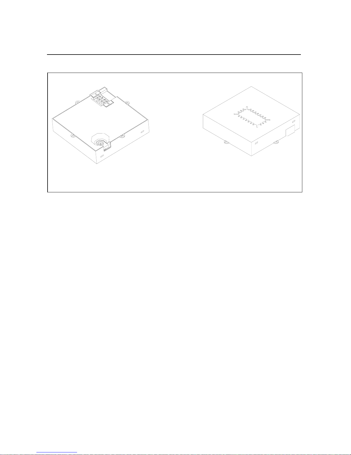
The Lassen iQ GPS receiver is a single module encased in a sturdy
metal enclosure. The dimensions of the receiver in this enclosure are
26 mm H x 26 mm L x 6 mm H (1.02” W x 1.02” L x 0.24” H). A
straight-in, panel-mount RF connector (J1) supports the GPS antenna
connection. The center conductor of the coaxial connector also
supplies +3.3 VDC for the Low Noise Amplif ier of the acti ve antenna.
An 8-pin (2x4), 0.09 inch header (J2) supports the tw o serial interfaces
(CMOS TTL level), the pulse-per-second (PPS) signal (CMOS TTL
level), and the input power (+3.3 VDC). Figure 1.1 illustrates the
module in the metal enclosure.
8 Lassen iQ GPS Receiver
Page 19
Starter Kit 1
Bottom Shield
Figure 1.1 Lassen iQ GPS receiver Module
The interface motherboard includes a 9 to 32 VDC switching power
supply which provides re gulated +3 .3 VDC power to the receiver, and
contains circuitry which provides two RS-232 interface ports. A 3.6V
lithium backup battery enables quick hot starts. The TTL level PPS is
brought directly out to Pin 9 of the Port 2 DB9 connector on the front
of the interface unit.
The Starter Kit includes an AC/DC converter for powering the module
from an AC wall socket. The metal enclosure (see Figure 1.2.)
provides 2 DB9 interface port connectors, an antenna connector, and a
power connector. Port 1 and Port 2 are used for serial I/O.
Top Shield
Lassen iQ GPS Receiver 9
Page 20
1 Starter Kit
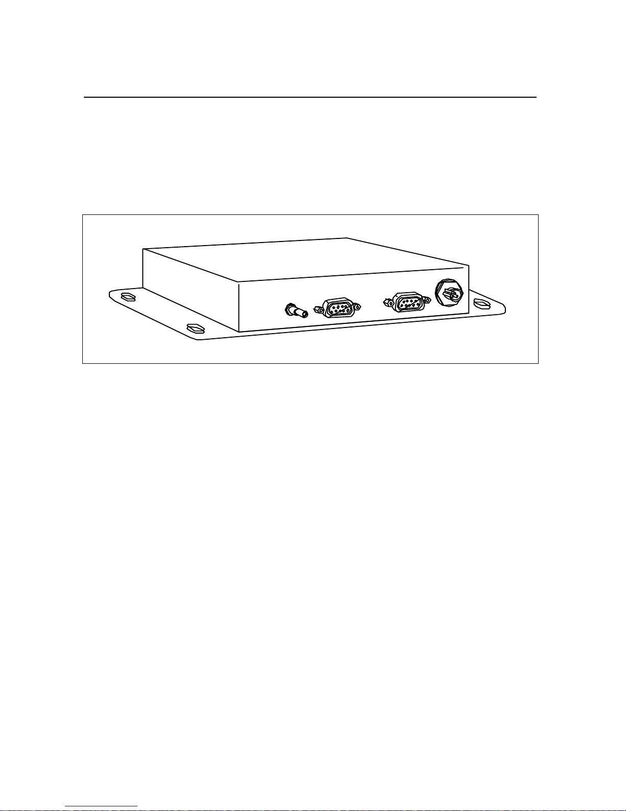
The mounting plate is secured to the metal enclosure with four screws.
The eight pin I/O header on the receiver module connects to a mating
connector on a ribbon cable. The ribbon cable is attached to a mating
I/O connector on the interface motherboard. Figure 1.2 illustrates the
Starter Kit interface unit.
Figure 1.2 Starter Kit Interface Unit
Port 2
Port 1
10 Lassen iQ GPS Receiver
Page 21

1.6.1 Serial Port Interface
The Starter Kit interface unit is a DCE (Data Communication
Equipment) device. To connect to a host computer, or DTE (Data
Term inal Equipment) device, use a straight through cable. To connect
a Differential Radio (DCE device) to the receiver (DCE Device) use a
cross over cable or null modem cable.
Table 1.2 Port 1 Pinouts
Pin Description
1NC
2TX
3RX
4NC
5GND
6NC
Starter Kit 1
7NC
8NC
9NC
Table 1.3 Port 2 Pinouts
Pin Description
1NC
2TX
3RX
4NC
5GND
6NC
7NC
8NC
9 PPS Out
Lassen iQ GPS Receiver 11
Page 22

1 Starter Kit
1.6.2 Pulse-Per-Second (PPS)
The Lassen iQ GPS receiver provides a four microsecond wide,
CMOS compatible TTL level Pulse-Per-Second (PPS). The PPS is a
positive pulse available on pin 9 of the port 2 DB9 connector of the
interface unit (see Table 1.3). The rising edge of the PPS pulse is
synchronized with respect to UTC. The timing accuracy is ±50
nanoseconds when valid position fixes are being reported.
The rising edge of the pulse is typically less than 20 nanoseconds. The
distributed impedance of the attached signal line and input circuit can
affect the pulse shape and rise time. The PPS can drive a load up to
5mA without damaging the module. The falling edge of the pulse
should not be used. The PPS is always on (early PPS) and is dri v en by
the Real Time Clock (RTC) until the receiver acquires GPS time from
the satellite and generates position fixes. The PPS is output
immediately after main power is applied, and continues even if the
receiver loses GPS lock. The drift of the PPS, when the receiver is not
tracking satellites, is unspecified and should not be used for
synchronization.
Note – Trimble has measured better than 50 nanosecond accuracy on
the Lassen iQ GPS receiver’s PPS signal in static mode. For more
information on use of the Lassen iQ GPS receiver in timing
applications, contact your Trimble sales representative.
12 Lassen iQ GPS Receiver
Page 23
1.7 Power
Starter Kit 1
The Lassen iQ GPS receiver receiver is designed for embedded
applications and requires a regulated +3.3 VDC input (+3.0 to +3.6
VDC). The receiver provided in the Starter Kit is installed on a
motherboard, providing a DC power regulator which converts a 9 to
32 VDC input to the regulated 3.3 VDC required by the receiver.
Power can be applied to the interface unit using one of three options:
the DC power cable (Figure 1.3), the AC/DC power converter
(Figure 1.4), or the cigarette lighter adapter.
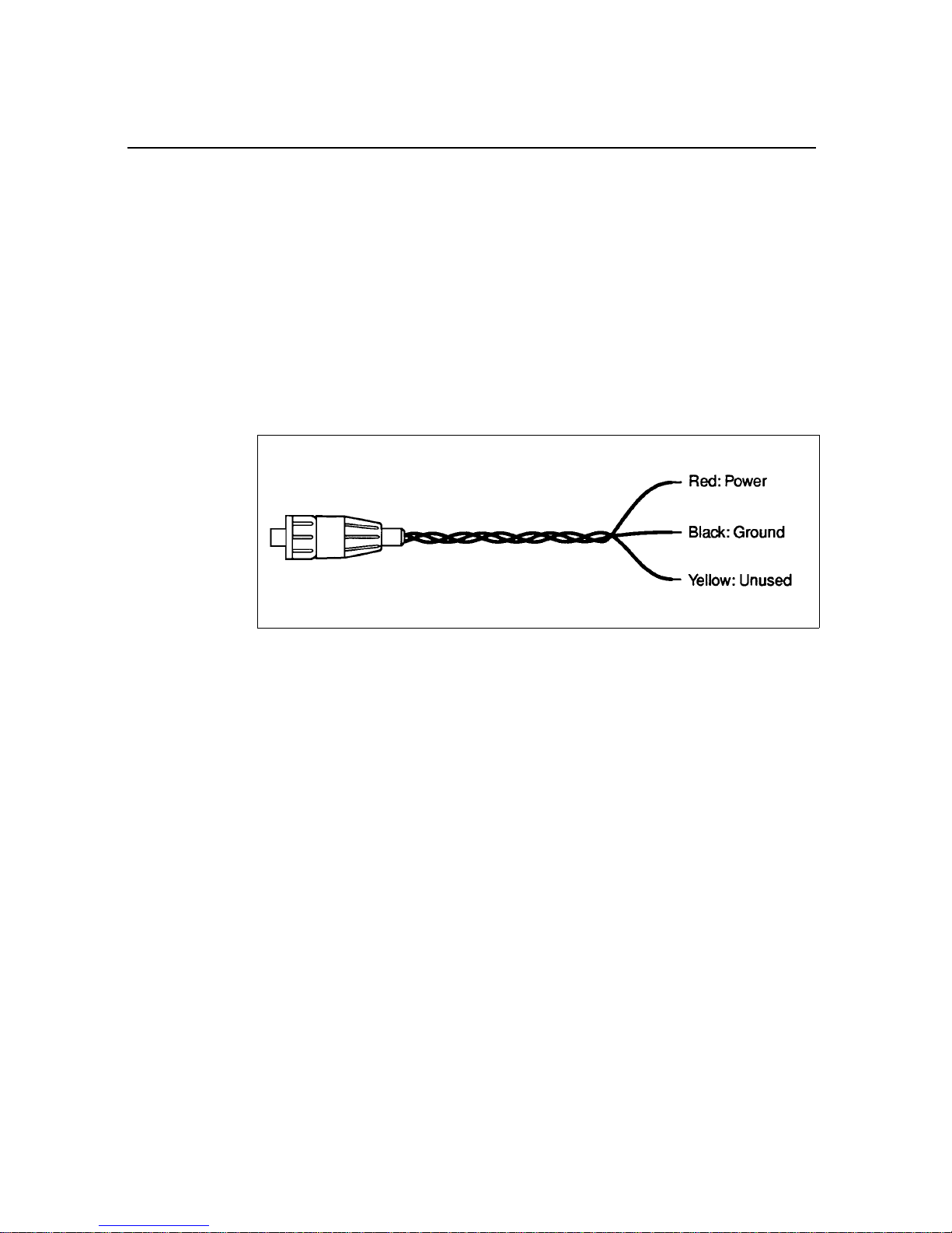
Figure 1.3 DC Power Cable
The DC power cable is ideal for bench-top or automotive testing
environments. The power cable is terminated at one end with a 3-pin
plastic connector which mates with the power connector on the metal
enclosure. The un-terminated end of the cable provides easy
connection to a DC power supply. Connect the red power lead to a
source of DC positive +9 to +32 VDC, and connect the black power
lead to ground. This connection supplies power to both the receiver
and the antenna.
Note – To ensure compliance with CE conducted emissions
requir ements when using the DC power cable, the Starter Kit interface
unit must be bonded to a ground plane.
Note – The yellow wire of the DC power cable is not used. Battery
back-up power is provided by a factory installed 3.6V lithium battery
on the motherboard.
Lassen iQ GPS Receiver 13
Page 24
1 Starter Kit
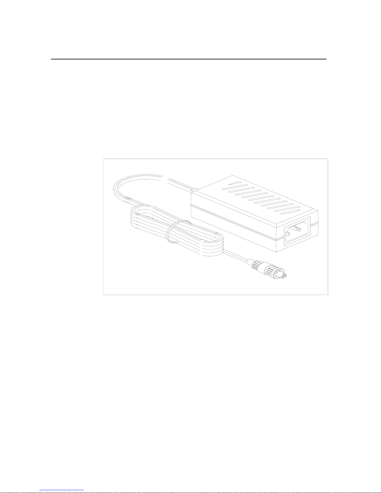
The AC/DC po wer con verter may be used as an alternate po wer source
for the interface unit. The AC/DC po wer con verter co nv erts 110 or 220
VAC to a regulated 12 VDC compatible with the interface unit. The
AC/DC power converter output cable is terminated with a 3-pin
connector compatible with the power connector on the metal
enclosure. The AC power cable is not provided in the kit, since this
cable is country-specific. The input connector is a standard 3-prong
connector used on many desktop PCs.
Figure 1.4 AC/DC Power Converter
14 Lassen iQ GPS Receiver
Page 25
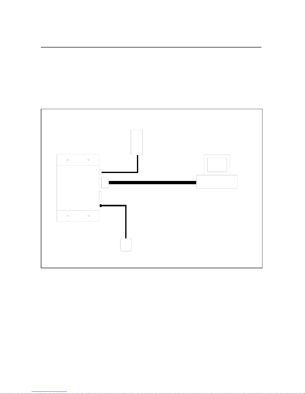
1.8 Hardware Setup
r
The Lassen iQ GPS receiver supports the TSIP and NMEA protocols.
A single port supports both the input/output of TSIP messages and the
output of NMEA messages. Follow the steps belo w to setup the Starter
Kit
interface unit. Figure 1.5 illustrates the setup.
Starter Kit 1
Po w e
Supply
Lassen iQ GPS
Star ter Kit
GPS
DCE
9 to 32 VDC
Re c e i v e r
DCE
GPS
Antenna
Figure 1.5 Starter Kit Interface Unit
DTE
Computer
Lassen iQ GPS Receiver 15
Page 26

1 Starter Kit
1. For use with the TSIP or TAIP protocols, connect one end of the
9-pin serial interface cable to Port 1 (or Port 2 to view NMEA
data) of the receiver module. Connect the other end of the cable
to COM1 or COM2 on a PC. If your PC has a 25-pin
communication port, a 9-pin-to-25-pin adapter may be requ ired
for this serial interface connection.
2. Connect the antenna cable to the interface unit. This connection
is made by pushing the antenna cable connector onto the MCX
connector on the module. Place the antenna so that it has a clear
view of the sky.
Note – To remove the antenna cable, grasp the antenna mating MCX
connector and pull from the MCX connector mounted on the interface
unit.
3. Using either the DC po wer cable or an A C/DC po wer converter,
connect to the 3-pin power connector on the interface unit.
– DC Power Cable — connect the terminated end of the
power cable to the power connector on the interface unit.
Connect the red lead to DC positive voltage (+9 to +32
VDC) and black power lead to DC ground. The yellow
wire is not used. Switch on the DC power source.
– AC/DC Po wer Con verter — connect the output cable of the
Warning – If the Lassen iQ GPS Starter Kit is powered-up and attached to
a PC COM port, the Windows operating system may recognize the Starter
Kit as a new serial device and assign it to the mouse driver. This can
cause erratic mouse control. To disable serial mouse detection at start-up,
add one of the following lines in the BOOT.INI file in the root directory:
/NOSERIALMICE (detection is disabled on all serial ports) or
/NOSERIALMICE=COMx,COMy,COMz (detection is disabled on one or
more specified com ports)
16 Lassen iQ GPS Receiver
converter to the 3-pin power connector on the interface
unit. Using the appropriate 3-prong AC power cable (not
provided), connect the conv erter to an AC wall socket (110
VAC or 220 VAC). The AC power cable is not provided in
the Starter Kit.
Page 27

1.9 Software Toolkit
The CD provided in the Starter Kit contains the iQ_Monitor, the
iQ_CHAT, and the GPSSK interface programs used to monitor GPS
performance and to assist system integrators in developing a software
interface for the GPS module. These applications are described in
detail in Appendix B, TSIP User's Guide.
iQ_Monitor runs on the Windows 95/98/2000/XP platforms.
iQ_CHAT runs under the DOS operating system on a 386 or higher
processor.
Following are quick start instructions for using the iQ_Monitor
application to monitor the receiver’s performance.
1. Connect one end of the serial interface cable to Port 1 of the
interface unit. Connect the other end of the cable to the COM
port of your PC.
2. Turn on the DC power source or plug in the AC/DC converter.
Starter Kit 1
3. Insert the CD in the computer’s CD-ROM drive.
4. The iQ_Monitor program may be run directly off the CD or it
may be copied onto your computer’s hard drive. To run the
program off the CD, initiate the iQ_Monitor.exe file.
5. When the iQ_Monitor screen appears, the TX and RX
indicators appear in the lower left corner of the status bar. A
blinking TX indicates that the PC is transmitting commands to
the receiver; a blinking RX indicates that the PC is receiving
reports from the receiver. If either of these indicators stop
blinking, there is no activity. The PC COM port settings appear
in the lower right corner of this same status bar.
6. After a GPS antenna is connected to the receiver and the
receiver has achieved a position fix, the transmitted position
reports, time, velocity, satellites tracked, and GPS receiver
status appear on the screen. The receiver also sends a health
report every few seconds, even if satellites are not being
tracked.
Lassen iQ GPS Receiver 17
Page 28

1 Starter Kit
Note – If the iQ_Monitor program displays a question mark (?) in a
data field, the receiver has not reported a status for this field. If a (?)
remains in the data field, the GPS module may not be communicating
with the computer. Re-check the interface cable connections and verify
the serial port selection and settings. If the communication failure
continues after checking all connections and settings, please call the
Trimble Technical Assistance Center (TAC) at 1 (800) 767-4822.
18 Lassen iQ GPS Receiver
Page 29

CHAPTER
2
Hardware Integration 2
In this chapter:
■ General Description
■ Connectors
■ Power Requirements
■ Serial Interface
■ Pulse-Per-Second (PPS)
■ Mounting
■ GPS Antennas
Page 30
2 Hardware Integration
2.1 General Description
Trimble’s new Lassen iQ GPS receiver adds complete GPS
functionality to mobile products, in a postage-stamp-sized footprint
with ultra-low power consumption. Using Trimble’s breakthrough
FirstGPS™ architecture, the module delivers complete position,
velocity and time (PVT) solutions for use in mobile, battery-powered
applications such as hand-held devices, PDAs, asset tracking devices,
and navigation applications.
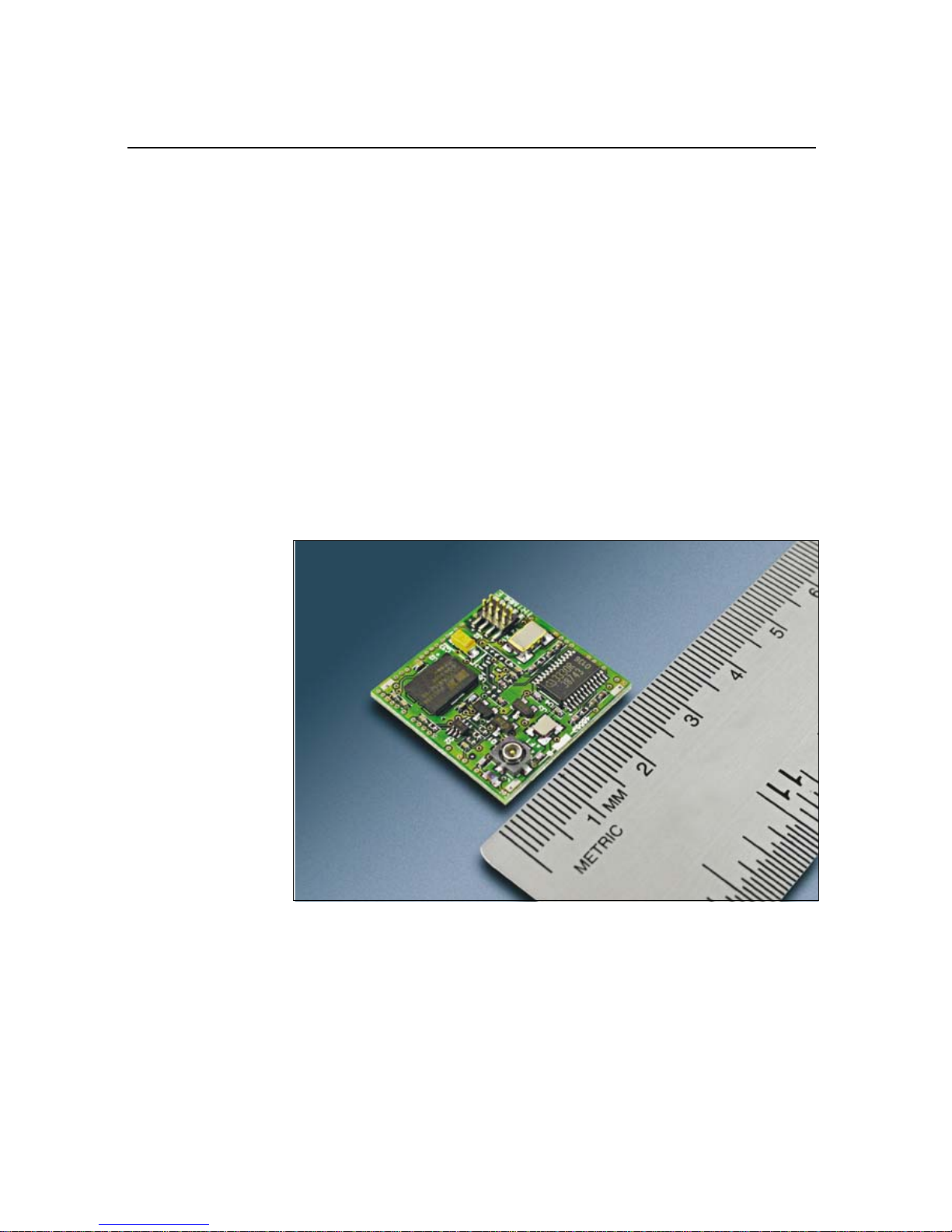
The Lassen iQ GPS module is packaged in a tiny form factor
(26 mm x 26 mm x 6 mm, including the metal shield). It typically
requires only less than 89 mW of power (at 3.3 VDC). The module
includes flash memory for firmware upgrades and storing the user
configuration.
Figure 2.1 Lassen iQ GPS Receiver Board without Shield
20 Lassen iQ GPS Receiver
Page 31

2.2 Connectors
2.2.1 Digital IO/Power Connector
The Lassen iQ GPS module uses a single 8-pin (2x4) male header
connector for both power and data I/O. The power and I/O connec to r,
J2, is a surface mount micro terminal strip. This connector uses 0.09
inch (2.286mm) high pins on 0.05 inch (1.27mm) spacing. The
manufacturer of this connector is Samtec, part number
ASP 69533-01.
Note – See Appendix F for mechanical drawings and specifications.
Mating Connectors
The customer must supply his own mating connector to the Lassen iQ
GPS receiver 8-pin (2x4) connector. There are two mating connectors
available:
Hardware Integration 2
• Surface-Mount Mating Connector
A recommended surface mount mating connector is Samtec’s
part number CLP-104-02.
When a surface-mount mating connector is chosen, the RF
connector must be attached to the Lassen iQ GPS module prior
to securing the module to the user’s PCB. The mounting tabs
may be used for securing the Lassen iQ GPS module to the PCB
when using the surface-mount mating scheme.
Lassen iQ GPS Receiver 21
Page 32

2 Hardware Integration
• Cable Strip Mating Connector
A low profile, cable strip mating connector is the second I/O
mating method. A recommended cable strip part is Samtec’s
part number FFSD-04-?-XX part. The user will need to
substitute the following letters and numbers into the part
number when ordering this part where the '?' and 'XX' symbols
occur: for the '?' symbol substitute the letter S for single end or
D for double end; for the 'XX' symbol substitute the overall
length in inches, ± 1/8 inch, with a 2 inch minimum. Since the
signals are CMOS TTL level signals, Trimble does not
recommend cable lengths of longer than six inches.
If the cable strip I/O connector scheme is used, the connector
side of the Lassen iQ GPS receiver will be facing up and the
mounting tabs will be on the top of the module away from PCB.
The RF connector is easily accessible, using this interfacing
methodology.
Figure 2.2 Cable Strip Mating Connector
22 Lassen iQ GPS Receiver
Page 33

2.2.2 RF Connector
The RF connector mounted on the Lassen iQ GPS receiver is a Hirose
connector, part number H.FL-R-SMT (10) 50 Ohm. The mating RF
connector is Hirose H.FL-LP-XXX where XXX depends on the cable
type.
Hardware Integration 2
Figure 2.3 Lassen iQ GPS Module with Connectors
Possible cable manufactures include the following:
• 1.48 mm diameter (single shield) cable:
– CO-6F/FH-SB manufactured by Hitachi Cable Ltd.
– UL1979 manufactured by Junkosha Co., Ltd.
– 0.8DS-PBE manufactured by Sumitomo Electric Industry
Co., Ltd.
• 1.32 mm diameter cable (double shield):
– A12B0733 manufactured by Junkosh a Co ., Ltd.
• 1.47 mm diameter cable (single shield):
– CXN2571 manufactured by W.L. Gore & Associated, Inc.
Lassen iQ GPS Receiver 23
Page 34

2 Hardware Integration
Trimble of fers three antennas for use with the Lassen iQ GPS receiver
receiver: The Ultra-Compact Embedded Antenna, which mates
directly to the RF connector. The Compact Unpackaged Antenna and
the Compact Magnetic-Mount Antenna, which mate through the
optional RF transition cable to the module’s RF connector. For more
information on the antennas, see page 33.
2.2.3 Digital IO/Power Connector Pinout
The digital IO/Power connector pinout information is listed in
Table 2.1.
Table 2.1 J2 I/O Conn ec tor Signals
Pin number Function Description
1 TXD A Serial Port A transmit, 3.3 V TTL
CMOS
2 GND Ground, Power and Signal
3 RXD A Serial Port A receive, 3.3 V TTL CMOS
4 PPS Pulse-Per-Second, 3.3 V TTL CMOS
5 TXDB Serial port B transmit, 3.3V TTL CMOS
6 RXDB Serial port B receive, 3.3V TTL CMOS
7 Prime Power (VCC) +3.3 VDC to
8 Battery Backup
Power
+2.5 VDC to + 3.6 VDC
± 0.3 VDC
24 Lassen iQ GPS Receiver
Page 35

2.3 P ower Requirements
The Lassen iQ GPS module requires +3.3 VDC ±0.3 VDC at 33 mA,
typical excluding the antenna. The on-board capacitance is 10 µF. An
important design consideration for power is the module's internal
clock frequency at 12.504 MHz ± 3 KHz. Interference spurs on prime
power in this narrow frequency band should be kept to less than 1mV.
The receiver does not require any special power up or down
sequencing. The receiver power is supplied through pin 7 of the I/O
connector. See Table 2.2 for the +3.3 VDC power specifications.
Warning – The Lassen iQ GPS receiver is ready to accept TSIP
commands approximately 2.1 seconds after power -up. If a command is
sent to the receiver within this 2.1 second window, the receiver will ignore
the command. The Lassen iQ GPS receiver will not respond to commands
sent within the 2.1 second window and will discard any associated
command data.
Hardware Integration 2
Battery Back-up
The Lassen iQ GPS receiver provides an input for battery back-up
(BBU) power to keep the module's RAM memory alive and to power
the real-time clock when the receiver's prime power is turned off.
RAM memory is used to store the GPS almanac, ephemeris, and last
position. User configuration data, including port parameters and
receiver processing options can be stored in non-volatile Flash which
does not require back-up power. By using battery back -up, time to first
fix in a hot start is reduced to 10 seconds (typical). Though not
required, providing BBU power can reduce time to first fix. A 3.6 v olt
lithium battery used for back-up power can last up to three years.
Lassen iQ GPS Receiver 25
Page 36

2 Hardware Integration
Warning – If battery power is not present, the receiver’s power can be
turned off and then back on to force a system reset and a cold start. The
receiver should be off for no less than 3 minutes to ensure that the RAM
memory does not retain any old data due to the residual voltage from the
power supply. To avoid waiting the 3 minutes, turn the receiver unit back
on immediately and issue TSIP command 0x1E with the value 4B. This
packet forces a cold start and clears battery backed RAM.
Note – 2.5V is the minimum allowable battery back-up voltage. When
the battery back-up power output dr ops below 2.5V, the real-time clock
may not operate over the specified temperature range. This can also
significantly extend the time to first fix. Trimble does not recommend
the use of Super Caps as battery back-up.
Table 2.2 Power Requirements
Signal Voltage Current J2 Pin #
VCC 3.0 to 3.6 27 mA 7
Battery Back-up 2.5 to 3.6 20µA
(at 3.3 volts, +25
Ground 0 -- 2
8
°C)
Note – For proper operation when using battery back-up , the voltage
value of the battery should be 10% less than the value of the VCC.
26 Lassen iQ GPS Receiver
Page 37

2.4 Serial Interface
As an embedded design, the Lassen iQ GPS module provides direct
CMOS compatible TTL level serial I/O. The RX and TX signals on
the J2 I/O connector are driven directly by the DUART on the Lassen
iQ GPS receiver. Interfacing these signals directly to a UART in your
application circuitry provides direct serial communication without the
complication of RS-232 or RS-422 line drivers.
Note – The serial I/O signals on J2 are TTL level. They are not
inverted or driven to RS-232 levels.
Hardware Integration 2
Lassen iQ GPS Receiver 27
Page 38

2 Hardware Integration
2.5 Serial Port Connections
Below are the required connections for the Lassen iQ GPS Rx pins
when they are not used for communication. This is required for
firmware release 1.10 and recommended for all subsequent firmware
releases.
Table 2.3 Serial Port Connections for Rx Pins
Serial Port Pin # Assignment Default Required
1 Pin 3 RxA TSIP-IN High (VCC)
2 Pin 6 RxB RTCM-IN High (VCC)
Below are the allowable connections for the Lassen iQ GPS Tx pins
when the pins are not used for communication. This configuration
applies to all firmware versions.
Connections
(via pullup)
(via pullup)
Table 2.4 Serial Port Connections for Tx Pins
Serial Port Pin # Assignment Default Allowable
1 Pin 1 TxA TSIP-OUT Floating or High
2 Pin 5 TxB NMEA-OUT Floating or High
Note – Attaching the Tx lines (pins 1 and 5) to VCC and using pullup
resistors is not required. Use of pullup r esistor s and at taching to VCC
on Rx lines (pins 3 and 6) is mandatory (for f irmwar e release 1.10 and
recommended for subsequent firmware releases) if these pints are not
otherwise connected to the system’s communication ports.
28 Lassen iQ GPS Receiver
Connections
(VCC) (via pullup)
(VCC) (via pullup)
Page 39

Hardware Integration 2
Below are the failure modes that will be experienced if the Lassen iQ GPS
pins are not connected as recommended (see above).
Table 2.5 Serial Port Connections for Tx and Rx Pins
Pin # High (VCC) Low (GND) Floating
Pin 1
(TxA, SI01
Pin 3
RxA, SI01
Pin 5
(TxB, SI02
Pin 6
RxB, SI02
Works Board will be
damaged
Works Will never produce a
position fix
Works Board will be
damaged
Works Do not choose this
option! Operation
cannot be
guaranteed. Failure
modes: may never
produce a position
fix, may output
potentially bad fixes
intermittently
Works
Do not choose this
option for firmware
release 1.10.
Operation cannot be
guaranteed. Failure
mode: will never
produce a position fix
Works
Do not choose this
option for firmware
release 1.10.
Operation cannot be
guaranteed. Failure
modes: may never
produce a position fix,
may output potentially
bad fixes
intermittently
Note – The table above indicates that the Tx pins 1 and 5 should not
be tied to Ground. As there are no internal pullups or current limiting
resistors, tying Tx to Ground will directly pull down the VCC rail
through the chip. This will pull excessive current, stressing the chip
beyond specification until it eventually fails.
Lassen iQ GPS Receiver 29
Page 40

2 Hardware Integration
2.5.1 Pullup Resistor
A pullup resistor should be added to the board in the range of 1K to
100K ohms for connecting the above-mentioned pins to VCC. One
end of the pullup resistor is connected to the iQ pin and the other end
is connected to the positive supply voltage VCC.
Note – The pullup resistor does not have to be powered by VCC. A
separate power source can be used, as long as it is not greater tha n
VCC. The minimum power for the pullup is 2.0V.
Resistor Impact on PCB Power Consumption
The pullups do not affect the Lassen iQ GPS power consumption since
the resistors will be external to the board. The overall power
consumption of the user’s PCB will increase slightly. Assuming 3.3V
VCC and 100k-pullup resistor, the power consumption increase will
be 109uW or 33uA per pullup. With a 1k pullup resistor, the power
consumption increase will be 10.9mW or 3.3mA per pullup.
To reduce the current draw, the users can choose higher value pullup
resistors in the allowable resistor range of 1K-100K ohms. To
minimize the overall power consumption of the user’s board, 100K
ohms pullup can be selected.
To keep BOM items to a minimum, the user can choose the highest
value resistor used on their board.
30 Lassen iQ GPS Receiver
Page 41

2.6 Pulse-Per-Second (PPS)
The Lassen iQ GPS receiver provides a four microsecond wide,
CMOS compatible TTL level Pulse-Per-Second (PPS). The PPS is a
positive pulse available on pin 4 of the power and I/O connector. The
rising edge of the PPS pulse is synchronized with respect to UTC. The
timing accuracy is ±50 nanoseconds when valid position fixes are
being reported.
The rising edge of the pulse is typically less than 20 nanoseconds. The
distributed impedance of the attached signal line and input circuit can
affect the pulse shape and rise time. In early PPS mode, the PPS can
drive a load up to 5mA without damaging the module. The falling
edge of the pulse should not be used. In it’s default mode PPS is
always on (early PPS) and is driven by the Real Time Clock (RTC)
until the receiver acquires GPS time from the satellite and is getting
fixes. In early PPS mode, the PPS is output immediately after main
power is applied, and continues even if the receiver loses GPS lock.
The drift of the PPS, when the Lassen iQ GPS receiver is not tracking
satellites, is unspecified and should not be used for synchronization.
Hardware Integration 2
The PPS output modes can be controlled with TSIP packet 0x35. The
modes are Always on (default), Fix Based, or Al ways Of f. Cable delay
compensation is available through the use of TSIP packet 0x8E-4A.
After a specific mode is selected, it can be stored in non-volatile
memory (FLASH) using TSIP command 0x8E-26. For more
information, see Appendix A.
Note – Trimble Navigation has measured better than 50 nanoseconds
accuracy on the Lassen iQ GPS receiver PPS signal in static mode.
For more information on the use of the Lassen iQ GPS module in
timing applications, contact your Trimble sales representative.
Lassen iQ GPS Receiver 31
Page 42

2 Hardware Integration
2.7 Mounting
The Lassen iQ GPS PCB is encased in a metal enclosure. The
enclosure acts as a protective case. There are four mounting solder
tabs on the bottom of the enclosure. When the surface-mount mating
connector is used, the mounting tabs may be used for securing the
Lassen iQ GPS module on the user’s PCB. When the cable strip I/O
connector scheme is used, the connector side of the Lassen iQ GPS
module will be faced up and the mounting tabs will be on the top of
the module away from PCB.
The Lassen iQ GPS module can be attached to the integrator platform
by many methodologies including solder, glue, double sided adhesive
tape, and custom hold down mounts for the module's mounting tabs.
Note – See Appendix F for mechanical drawings and specifications
regarding the spacing of the mounting tabs and the dimensions of the
enclosure.
32 Lassen iQ GPS Receiver
Page 43

2.8 GPS Antennas
The antenna receives the GPS satellite signals and passes them to the
receiver. The GPS signals are spread spectrum signals in the 1575
MHz range and do not penetrate conductive or opaque surfaces.
Therefore, the antenna must be located outdoors with a clear view of
the sky. The Lassen iQ GPS receiver requires an active antenna. The
received GPS signals are approximately -130 dBm, at the surface of
the earth (in typical environments). T rimble's active antennas include a
preamplifier that filters and amplifies the GPS signals before delivery
to the receiver.
Trimble of fers three antennas for use with the Lassen iQ GPS receiver
described below and in Appendix D.
1. The Ultra-Compact Embedded GPS Antenna with an HFL
connector, is ideal for portable and mobile applications. This
unpackaged antenna is approximately the same size as the
module itself, and can be easily integrated into mobile
applications. This antenna is supplied with the Starter Kit (see
Figure 2.4).
Hardware Integration 2
2. A Compact Unpackaged Antenna with an MCX connector,
slightly larger than the ultra-compact model (see #1 above),
mates to the Hirose connector on the Lassen iQ GPS module
with an optional RF transition cable (see Figure 2.5).
Lassen iQ GPS Receiver 33
Page 44

2 Hardware Integration
3. A Compact Magnetic-Mount GPS Antenna with a 5 m cable
Warning – When magnetic-mount or permanent-mount GPS antennas
are installed on a metal surface for prolonged periods, care must be taken
to insulate the antennas in order to prevent galvanic corrosion.
and an MCX or SMA connector. This antenna provides for a
flexible, movable installation. The MCX or SMA output
connector mates to the Hirose connector on the Lassen iQ GPS
module with an optional RF transition cable. The antenna with
the MCX connector is supplied with the Starter Kit (see
Figure 2.6). The MCX connector on the end of the antenna
cable mates to the MCX connector in the front of the Starter Kit
interface unit. The two scre w holes on the bottom of the antenna
can be used to mount the antenna to a metal plate. The
dimensions of these holes are 2.06 mm in diameter and 5mm in
depth.
34 Lassen iQ GPS Receiver
Page 45

Hardware Integration 2
Figure 2.4 Ultra-Compact Embedded GPS Antenna
Figure 2.5 Compact Unpackaged GPS Antenna
Figure 2.6 Compact Magnetic-Mount GPS Antenna
Lassen iQ GPS Receiver 35
Page 46

2 Hardware Integration
36 Lassen iQ GPS Receiver
Page 47

CHAPTER
3
Software Interface 3
In this chapter:
■ Start-up
■ Communicating with the Lassen iQ GPS Receiver
■ Port Protocol and Data Output Options
■ Custom Port Configuration
■ When prompted, select the factory default option.
Page 48

3 Software Interface
3.1 Start-up
Lassen iQ GPS receiver module is a complete 12-channel parallel
tracking GPS receiver designed to operate with the L1 frequency,
standard position service, Coarse Acquisition code. When connected
to an external GPS antenna, the receiver contains all the circuitry
necessary to automatically acquire GPS satellite signals, track up to 12
GPS satellites, and compute location, speed, heading, and time. The
receiver will automatically begin to search for and track GPS satellite
signals at power-up.
The performance of a GPS receiver at power-on is determined largely
by the availability and accurac y of the satellite ephemeris data and the
availability of a GPS system almanac.
The first time the receiver is powered-up, it is searching for satellites
from a cold start (no almanac). While the receiver will begin to
compute position solutions within the first two minutes, the receiver
must continuously track satellites for approximately 15 minutes to
download a complete almanac. This initialization process should not
be interrupted. With a complete almanac and back-up power, the time
to first fix can typically be shortened to less than 42 seconds. The
receiver will respond to commands almost immediately after power-up
(see Warning below).
Note – See Chapter 4 for further detail on ephemeris data and the
GPS almanac.
Warning – The Lassen iQ GPS Receiver is ready to accept TSIP
commands approximately 2.1 seconds after power -up. If a command is
sent to the receiver within this 2.1 second window, the receiver will ignore
the command. The Lassen iQ GPS Receiver will not respond to
commands sent within the 2.1 second window and will discard any
associated command data.
38 Lassen iQ GPS Receiver
Page 49

Software Interface 3
3.2 Communicating with the Lassen iQ GPS Receiver
The Lassen iQ GPS Receiver supports three message protocols: TSIP,
TAIP, and NMEA. Communication with the module is through two
CMOS compatible, TTL level serial ports. The port characteristics can
be modified to accommodate your application requirements. Port
parameters can be stored in non-volat ile memory (FLASH) which
does not require backup power. Table 3.1. lists the default port
characteristics.
3.2.1 Software Tools
The Software Tools provided on the Starter Kit CD-ROM include both
user friendly Windows and DOS applications to facilitate
communication with the receiver, via the Trimble Standard Interface
Protocol (TSIP). This CD also includes sample C source code and
reusable routines to aid in developing applications.
Note – The TSIP, TAIP, and NMEA protocols are discussed beginning
on page 42 of this chapter, and in the Appendices of this document.
Lassen iQ GPS Receiver 39
Page 50

3 Software Interface
3.2.2 Port Configuration
The Lassen iQ GPS receiver module has two I/O ports. Table 3.1
provides the default protocols and port configurations for the receiv er,
as delivered from the factory. TSIP IN/OUT is the default protocol on
Port 1 and RTCM-IN and NMEA-OUT is the default protocol on
Port 2.
Table 3.1 Default Protocols and Port Configurations
Port Input
Protocol
1 TSIP Baud Rate: 9600
2 RTCM Baud Rate: 4800
Default Setup
Data Bits: 8
Parity: Odd
Stop Bits: 1
No Flow Control
Data Bits: 8
Parity: None
Stop Bits: 1
No Flow Control
Output
Language
TSIP Baud Rate: 9600
NMEA Baud Rate: 4800
Default Setup
Data Bits: 8
Parity: Odd
Stop Bits: 1
No Flow Control
Data Bits: 8
Parity: None
Stop Bits: 1
No Flow Control
The Lassen iQ GPS Receiver can also be configured to output TAIP
messages. The Trimble standard port characteristics for TAIP are:
• Baud Rate: 4800
• Data Bits: 8
• Parity: None
• Stop Bits:1
•No Flow Control
Any standard serial communications program, such as Windows
Hyper-Terminal or PROCOMM, can be used to view the NMEA or
TAIP output messages. TSIP is a binary pro t ocol and outputs raw
binary serial data that cannot be read when using Windows Terminal
or PROCOMM. To view the output of the TSIP protocol in text
format, use the iQ_CHAT or the iQ_Monitor program (see the CDROM provided in the Starter Kit).
40 Lassen iQ GPS Receiver
Page 51

Software Interface 3
The serial port driver in the iQ_CHAT Tool Kit matches the Lassen iQ
GPS receiver serial port characteristics. The TSIPPRNT program
converts binary data logged with the
iQ_CHAT program into text that
may be printed and displayed. Both of these tools are included in the
Software Developer’s Toolkit.
Warning – When using the TSIP protocol to change port assignments or
settings, confirm that your changes do not affect the ability to
communicate with the receiver (e.g., selecting the PC COM port settings
that do not match the receiver’s, or changing the output protocol to TSIP
while not using iQ_CHAT).
Lassen iQ GPS Receiver 41
Page 52

3 Software Interface
3.3 P ort Protocol and Data Output Options
3.3.1 Protocol Configuration and Interface
The factory default I/O protocol for Port 1 of the Lassen iQ GPS
receiver is the Trimble Standard Interface Protocol (TSIP) for both
input and output. The settings for Port 1 are 9600 baud 8-odd-1. The
factory default protocol for Port 2 is RTCM-IN and NMEA-OUT. The
settings for Port 2 are 4800 baud 8-none-1. The receiver pro tocol can
be re-configured using TSIP command packet 0xBC, in conjunction
with iQ_CHAT, iQ_Monitor, or a user written serial interface
program. See Appendix A for details on the 0xBC command packet.
iQ_CHAT provides the simplest means to communicate with the
receiver using a PC (386 or higher) running either the DOS or
Windo ws operating systems. Responses are displayed on the computer
monitor in text format.
iQ_Monitor, a Windows-based GUI, provides a versatile graphical
interface for monitoring TSIP data. This application allo ws the user to
view complete receiver operations including data output, status and
configuration. In this application, the entry of command packets is
replaced by traditional point and click pull-down menus.
C source code routines for iQ_CHAT are also provided on the CD
contained in the Starter Kit. When used as software design templates,
this source code can significantly speed-up code development.
The protocol settings and options are stored in battery-backed
Random-Access-Memory (BBRAM). They can also be saved into the
non-volatile memory (Flash), if desired, using command 0x8E-26. See
to Appendix A for additional information on Flash storage for custom
operation.
42 Lassen iQ GPS Receiver
Page 53

3.3.2 TSIP Data Output Modes
TSIP is the default protocol for Port 1 on the Lassen iQ GPS receiver.
This binary language offers users a wide variety of commands and
reports. TSIP enables the Lassen iQ GPS receiver to operate in two
data output modes, both available during operation. In Query Mode,
packet data is returned in response to input query packets. In
Automatic Mode, a selected group of data packets is output
continuously at two fix ed rates – e v er y second and every five seconds.
The format and ensemble of the automatic output packets is
configured using packets 0x35, 0x70, and 0x8E-20 (see Appendix A
for packet details). Packet settings are stored in BBRAM. They can
also be saved in non-volatile memory (Flash) using command packet
0x8E-26. See Appendix A for additional information on Flash storage
for custom operation.
3.3.3 Default TSIP Output Settings
Default 0x35 setting (byte 0=2, 1= 2, 2=0, 3=0):
Software Interface 3
• Position and v el ocity data precision: single precision floating point
• Position output option and format (byte 0 setting):
– Latitude – radian
– Longitude – radian
– Altitude – meters (WGS-84)
• No super-packet output
• Velocity output option and format:
– East Velocity – meters/sec.; + for East
– North Velocity – meters/sec.; + for North
– Up Velocity – meters/sec.; + for Up
• Timing
– GPS Time Output
– PPS Always ON
• Auxiliary/Pseudo Range Measurement
– Raw Measurements OFF
– Raw Pseudo Ranges OFF
– Output AMU val ue s
Lassen iQ GPS Receiver 43
Page 54

3 Software Interface
Default 0x70 setting (byte 0=1, 1=1. 2=1. 3=0):
• Position-Velocity Dynamic Filter enabled
• Position-Velocity static Filter enabled
• Altitude Filter enabled
Default 0x8E-20 setting (byte 1 = 1):
• 0x8F-20 o utput is included in the super-packet for automatic out put
IF packet 0x35 selects the super-packet for automatic output
options
3.3.4 Automatic TSIP Output Packets (fixed rate)
One second interval:
• 0x4A – (1) GPS position fix; (2) clock bias and time of fix; {20
byte format}
• 0x56 – velocity fix
• 0x6D – (1) list of satellites used for position fixes; (2) PDOP,
HDOP, VDOP; (3) fix mode
• 0x82 – DGPS position fi x mode
Five second interval:
• 0x41 – (1) GPS time of the week (seconds); (2) extended GPS
week number; (3) GPS UTC offset (seconds)
• 0x46 – health of receiver
• 0x4B – (1) Machine/Code ID; (2) Real-time-clock a vailability
status; (3) almanac validity status; (4) having super-packet support
status
44 Lassen iQ GPS Receiver
Page 55

3.3.5 Packet Output Order
After power up or a software reset (packet 0x1E), seven start-up
packets are sent, only once, by the receiver in this order: 45, 46, 4B,
4A, 56, 41, 82
Before position fixes are available, the 1 second and 5 second interval
packets are sent in this order, periodically:
• Every one second for 5 seconds: 6D, 82
• Every five seconds 41, 46, 4B
When position fixes are available, the 1 second and 5 second interval
packets are sent in this order, periodically:
• Every one second for 4 seconds: 4A, 56, 6D, 82
• Every 5 seconds: 4A, 56, 41, 46, 4B, 6D, 82
Software Interface 3
Lassen iQ GPS Receiver 45
Page 56

3 Software Interface
3.3.6 NMEA 0183 Protocol and Data Output Options
The National Marine Electronics Association (NMEA) protocol is an
industry standard data protocol which was developed for the marine
industry. Trimble has chosen to adhere stringently to the NMEA 0183
data specification as published by the NMEA. The Lassen iQ GPS
receiver also adheres to the NMEA 0183, Version 3.0 specification.
NMEA data is output in standard ASCII sentence formats. Message
identifiers are used to signify what data is contained in each sentence.
Data fields are separated by commas within the NMEA sentence. In
the Lassen iQ GPS receiver, NMEA is an output only protocol. The
NMEA protocol is described in detail in Appendix E.
The receiver is shipped from the factory with the TSIP protocol
configured on Port 1 and RTCM-IN/NMEA-OUT on Port 2. The Port
2 characteristics conform to the NMEA industry standard:
• 4800 baud
• 8 data bits
• No parity
• 1 st op bit
• No flow control
The receiver can be reconfigured using TSIP command packet 0xBC,
in conjunction with iQ_CHAT, iQ_Monitor, or a user written serial
interface program.
The NMEA output messages selection and message output rate can be
set using TSIP command packet 0x7A. The default setting on Port 2 is
to output the GGA and VTG messages at a 1 second interval.
If the NMEA configuration is permanently changed for the
application, the protocol configuration (0xBC) and NMEA message
output setting (0x7A) can be stored in the non-volatile memory (onboard FLASH) using TSIP command 0x8E-26.
46 Lassen iQ GPS Receiver
Page 57

3.4 Custom Port Configuration
iQ_CHAT can be used to customize the Lassen iQ GPS receiver
configuration settings and to save a configuration to non-volatile
memory. The most recent port configuration is stored in BBRAM.
This eliminates the need to repeat setup each time the receiver power
is cycled. However, if the battery-backed power is accidentally lost,
the port configuration automatically resets to either what wa s sa ved in
the non-volatile memory (FLASH) or to the factory default.
Tip – To ensure continuous operation, store all port configuration changes
in the non-volatile memory.
Following are step-by-step instructions for using iQ_CHAT to
customize Lassen iQ GPS receiver port configuration.
Customizing the Configuration
Software Interface 3
1. Insert the CD in the CD-ROM drive of your computer.
2. Open a DOS windo w and set the path to the iQ_CHAT location.
3. To run the program, type iQ_CHAT –c1 if attached to PC
COM1, or type iQ_CHAT –c2 if attached to PC COM2.
4. Power-up the receiver. Automatic report streams should be
scrolling up in the DOS window. Assuming that your receiver is
set to the default configuration, the settings will be: 9600 baud,
8-odd-1.
Note – If data is not being output after receiver power up, use the “^I”
command in iQ_CHAT to reset the COM1/COM2 setting in PC (not
the receiver).
Tip – Entering “?” in the iQ_CHAT window displays all the available
commands and their corresponding TSIP packets.
Lassen iQ GPS Receiver 47
Page 58

3 Software Interface
5. To re-configure the port settings and protocol, type “U” and
Saving the Configuration
1. Before storing the new configuration in FLASH, confirm that
Warning – Record the new serial port settings. If power is lost, this will
speed-up recovery. Alternatively, the receiver can always be returned to
the default configuration.
2. To save the configuration to Flash:
respond to the input prompts. At the end of this procedure,
select the option that resets the PC COM port to match the new
settings. Communication should resume almost immediately.
the receiver has been configured to the desired settings.
– Enter “=” to access the command list page for the 0x8E
command packet.
– Enter “s”, to send the 0x8E-26 command packet.
– Communication is momentarily suspended while the
configuration is being stored in Flash.
3. To confirm that the configuration changes have been saved,
turn-off the power supply and the battery back-up for a few
minutes. Then, power-up the receiver and confirm that the
configuration changes have been retained. Alternativ ely, you
can use Packet 1E to command a cold start.
Note – Command packet 0x8E-26 executes storage of various types of
receiver settings in addition to the port and pr otocol. See Table 3.2 for
a complete list of the settings that can be stored in FLASH memory.
48 Lassen iQ GPS Receiver
Page 59

Returning to the Factory Settings
At any time, the receiver can be returned to the factory default
configuration, using command packet 0x1E.
1. Type “^k” to invoke the 0x1E command.
2. When prompted, select the factory default option.
Table 3.2 iQ_CHAT Command Settings Stored in Flash Memory
Command Packet 0x8E-26
Software Interface 3
TSIP Command ID iQ_CHAT
Keystroke
0x35 ‘O’ TSIP input/output formatting
0x69 ‘e’ Enhanced Sensitivity Mode
0x70 ‘l’ Position filter controls
Description TSIP Response ID
– Superpacket output (on/off)
– Position format (LLA and/or
ECEF)
– Precision (double or single)
– altitude format (MSL or HAE)
– Timetag format (GPS or UTC)
– PPS modes
– SNR format (AMU or C/N
– Automatic pseudorange
output
Control
– Position filter on/off
– Static filter on/off
– Altitude filter on/off
0x55
0
0x89
0x70
0x7A ‘q’ NMEA message formats and
0x7e ‘a’ TAIP message formats and
0x7B
schedule
– NMEA output messages
– NMEA output interval
0x7F
schedules
Lassen iQ GPS Receiver 49
Page 60

3 Software Interface
Table 3.2 iQ_CHAT Command Settings Stored in Flash Memory
Command Packet 0x8E-26 (Continued)
TSIP Command ID iQ_CHAT
Description TSIP Response ID
Keystroke
0xBB ‘p’ GPS configuration parameters
– Operating dimension
(2D, 3D,...)
– DGPS mode
– Dynamics mode
– Elevation mask
–SNR mask
– DOP mask
– PDOP switch
– DGPS correction age
0xBC ‘U’ Serial port configuration
– Protocol: input, output
– Baud, data bits, parity, stop
bits
0x8E-20 ‘= g’ Fixed point superfix control
(default = on)
0xBB
0xBC
0x8F-20
50 Lassen iQ GPS Receiver
Page 61

3.5 Timing Applications
The Lassen iQ GPS receiver is an excellent source for accurate system
timing. Two examples of applications requiring accurate time are
environmental data acquisition and synchronization of
communications networks. The timing functions of the receiver are
supported by the TSIP protocol and the PPS signal. See Report Packet
0x41 or Super Packet 0x8F-20 in Appendix A for a description of the
time function reports for TSIP.
Note – GPS time differs from UTC (Universal Coordinated Time) by a
variable integer number of seconds: UTC = (GPS time) - (GPS UTC
Offset)
As of April 2002, the GPS UTC offset was 13 seconds. The offset
increases by 1 second approximately every 18 months. System
designers should plan to read the offset value as a part of the timing
interface to obtain UTC. The GPS week number is in reference to a
base week (Week #0), starting January 6, 1980.
Software Interface 3
The current GPS UTC offset is contained within the almanac
transmitted by the GPS system. The Lassen iQ GPS Receiver must
have a complete almanac before the offset data is valid.
Note – As of January 2005, the GPS Control Organization has not
added leap seconds on the usual 18 month schedule. As a result, the
offset has remained at 13 seconds.
3.5.1 Extended GPS Week Number
The Lassen iQ GPS Receiver outputs the Extended GPS Week
Number as the absolute number of weeks since the beginning of GPS
time or January 6, 1980. If the true GPS Week Number is desired,
ignore the extra MSBs of the Extended GPS Week Number and use
only the 10 LSBs (bytes 4 and 5 of Packet 0x41).
Note – After week number 2331, in year 2024, the TSIP week number
rolls back to 1308. All dates reported in NMEA and TAIP, will be
invalid.
Lassen iQ GPS Receiver 51
Page 62

3 Software Interface
3.6 Known Anomalies in Firmware Release 1.10
The following are know anomalies found in Lassen iQ FW v1.10.
These anomalies will be fixed in all follow on versions:
• Position outages during the Weekend Rollover
The receiver would experience satellites being dropped and thus
several seconds of position outages during the weekend rollover,
which happens during Saturday to Sunday at midnight each week.
This anomaly is found in Lassen iQ GPS receiver f irmw are version
1.10 and will be fixed in all future firmware releases.
• Position outages during WNRO (Week Number Rollover)
The receiver would experience satellites being dropped and thus
several seconds of position outages during the next week number
rollover, which will happen on April 7, 2019 (GPS time). This
problem is caused by the End-Of-the-Week Rollover problem as
End-Of-the-Week Rollover occurs during WNRO. Th is anomaly is
found in Lassen iQ GPS receiver f irmware v ersion 1.10 and will be
fixed in all future firmer releases.
• Extended TTFF times in year 2023 - 2024
The user would experience extended warm and hot startup times
between years 2023 to 2024. This anomaly is found in the Lassen
iQ GPS receiver firmware version 1.10 and will be fixed in all
future firmware releases.
• Static Filter issue
The static filter can be turned and stay on/off, based on user
configuration or by TSIP packet 0x70. However, when it is set to
off, it will be turned on internally after 255 position fixes are
generated. The query on the status of the static filter would still
indicate that it is being turned off ev en though it has been turned on
internally. This anomaly is found in Lassen iQ GPS receiver
firmware v ersion 1.10 and will be f ix ed in all future f irmer releases.
• TSIP packet 0x65 is not functional in Lassen iQ GPS receiver FW
v1.10. It will be fixed in all future firmware releases.
52 Lassen iQ GPS Receiver
Page 63

CHAPTER
4
Operation and Performance 4
In this chapter:
Introduction
GPS Satellite Message
Satellite Acquisition and Time to First Fix
Satellite Mask Settings
Standard Operating Modes
Position Accuracy
Coordinate Systems
Performance Characteristics
Lassen iQ GPS Receiver Sensitivity Modes
Lassen iQ GPS Receiver Aided GPS Feature
GPS Timing
System Architecture
Page 64

4 Operation and Performance
4.1 Introduction
This chapter describes the Lassen iQ GPS receiv er satellite acquisition
and tracking processes, performance characteristics, and system
architecture. This discussion assumes that you are familiar with the
basic theory of the Global Positioning System. Before proceeding to
the detailed discussion of the satellite acquisition and tracking process,
please revie w the GPS satellite message description on the next page.
The Lassen iQ GPS receiver satellite acquisition and tracking
algorithms can achieve a position solution without any initialization.
The receiver automatically selects and tracks the best combination of
satellites to compute position and velocity. As satellites move out of
view, the Lassen iQ GPS receiver automatically acquires ne w satellites
and includes them in the solution set as required.
54 Lassen iQ GPS Receiver
Page 65

4.2 GPS Satellite Message
Every GPS satellite transmits the Coarse/Acquisition (C/A) code and
satellite data modulated onto the L1 carrier frequency (1575.42 MHz).
The satellite data transmitted by each satellite includes a satellite
almanac for the entire GPS system, its own satellite ephemeris and its
own clock correction.
The satellite data is transmitted in 30-second frames. Each frame
contains the clock correction and ephemeris for that specific satellite,
and two pages of the 50-page GPS system almanac. The alman ac is
repeated every 12.5 minutes. The ephemeris is repeated every 30
seconds.
The system almanac contains information about each of the satellites
in the constellation, ionospheric data, and special system messages.
The GPS system almanac is updated weekly and is typically valid for
months. The ephemeris contains detailed orbital information for a
specific satellite. Ephemeris data changes hourly, but is valid for up to
four hours. The GPS control segment updates the system almanac
weekly and the ephemeris hourly through three ground-based control
stations. During normal operation, the Lassen iQ GPS receiver module
updates its ephemeris and almanac as needed.
Operation and Performance 4
The performance of a GPS receiver at power-on is determined largely
by the availability and accurac y of the satellite ephemeris data and the
availability of a GPS system almanac.
Lassen iQ GPS Receiver 55
Page 66

4 Operation and Performance
4.3 Satellite Acquisition and Time to First Fix
4.3.1 Cold-Start
The term “cold-start” describes the performance of a GPS receiver at
power-on when no navigation data is available. “cold” signifies that
the receiver does not have a current almanac, satellite ephemeris,
initial position, or time. The cold-start search algorithm applies to a
Lassen iQ GPS receiver which has no memory of its previous session
(i.e., is powered on without the memory backup circuit connected to a
source of DC power). This is the “out of the box” condition of the GPS
module as received from the factory.
In a cold-start condition the receiver automatically selects a set of
eight satellites and dedicates an individual tracking channel to each
satellite, to search the Doppler range frequency for each satellite in the
set. If none of the eight selected satellites is acquired after a predetermined period of time (time-out), the receiver will select a new
search set of eight satellites and will repeat the process, until the first
satellite is acquired. As satellites are acquired, the receiver
automatically collects ephemeris and almanac data. The Lassen iQ
GPS receiver uses the knowledge gained from acquiring a specific
satellite to eliminate other satellites, those below the horizon, from the
search set. This strategy speeds the acquisition of additional satellites
required to achieve the first position fix.
The cold-start search sets are established to ensure that at least three
satellites are acquired within the first two time-out periods. As soon as
three satellites are found, the receiver will compute an initial position
fix. The typical time to first fix is less than 2 minutes.
A complete system almanac is not required to achieve a first position
fix. However, the availability and accuracy of the satellite ephemeris
data and the availability of a GPS almanac can substantially shorten
the time to first fix.
56 Lassen iQ GPS Receiver
Page 67

4.3.2 Wa rm Start
In a warm-start condition the receiver has been powered down for at
least one hour but has stored a current almanac, an initial position, and
time, in memory.
When connected to an external back-up power source (battery
back-up), the Lassen iQ GPS receiver retains the almanac,
approximate position, and time to aid in satellite acquisition and
reduce the time to first fix. When an external back-up battery is not
used, the TSIP protocol allows the almanac, an initial position, and
time to be uploaded to the receiver via the serial port, to initiate a
warm start.
During a warm start, the Lassen iQ GPS receiver identifies the
satellites which are expected to be in view, given the system almanac,
the initial position and the approximate time. The receiver calculates
the elevation and expected Doppler shift for each satellite in this
expected set and directs the eight tracking channels in a parallel search
for these satellites.
Operation and Performance 4
The warm start time to first fix, when the receiver has been powered
down for more than 60 minutes (i.e. the ephemeris data is old), is
usually less than 45 seconds.
4.3.3 Hot Start
A hot start strategy applies when the Lassen iQ GPS receiv er has been
powered down for less than 60 minutes, and the almanac, position,
ephemeris, and time are valid. The hot start search strategy is similar
to a warm start, but since the ephemeris data in memory is considered
current and valid, the acquisition time is typically less than 20
seconds.
Lassen iQ GPS Receiver 57
Page 68

4 Operation and Performance
4.3.4 Garage Search Strategy
During a warm start search, the Lassen iQ GPS receiver knows which
satellites to search for, based on the system almanac, the initial
position (last known position) and the current time. In some cases, the
receiver may not be abl e to acquire the expected satellite signals (e.g.,
a vehicle parked in a garage or a vessel in a covered berth). Trimble's
patented “garage search” strategy, also known as a split search, is
designed for such situations.
If the receiver does not acquire the expected set of satellites within
5 minutes of power-on, some of the eight tracking channels will
continue to search for the expected satellites (warm search) while the
remaining channels are directed in a cold start search. This strategy
minimizes the time to first fix in cases where the stored almanac,
position and time are invalid. The stored information is flushed from
memory, if the cold start search proves effective and the warm search
fails.
4.3.5 System Reset
The Lassen iQ GPS receiver can be reset with software commands or
by cycling power. A system reset will cause the receiver to restart and
begin the satellite acquisition and tracking process again. There are
three types of system resets: soft reset, hard reset, and factory reset.
The TSIP protocol supports all three resets using the 0x1E command.
Power cycling can be used for either the soft reset or the hard reset.
A soft reset is a system restart. In a soft reset, the system will attempt
to acquire satellites using the satellite information and last position
data stored in RAM, and the time information supplied by the realtime clock. There are two ways to initiate a soft reset:
• Cycling main power while keeping the memory and the realtime clock alive with back-up power.
• Issuing Command Packet 0x25.
A soft reset is the same as a warm or hot start, if the information
contained in memory and supplied by the real-time clock is valid.
58 Lassen iQ GPS Receiver
Page 69

Operation and Performance 4
A hard reset is a system restart that results in satellite acquisition
search using a default search set. Any data contained within RAM
memory is discarded and the real-time clock is re-initialized. Even if
back-up power is supplied, the information from memory and the realtime clock is not used. There are two ways to initiate a soft reset:
• Issuing the 0x1E command with a value of 0x4B.
• Cycling power without back-up power applied. Using this
method, power must be removed for at least 3 minutes to ensure
any residual memory storage is erased. If power is cycled
rapidly, the 0x1E command with a value of 0x4B must then be
issued to the receiver 2.5 seconds after power is restored to
ensure a hard reset.
A factory reset is used to restore all the factory default settings into the
receiver. Any user settings stored in Flash memory will be erased.
Issuing the 0x1E command with a value of 0x46 will initiate a factory
reset.
Lassen iQ GPS Receiver 59
Page 70

4 Operation and Performance
4.4 Satellite Mask Settings
Once the Lassen iQ GPS receiver has acquired and locked onto a set of
satellites, which pass the mask criteria listed in this section, and has
obtained a valid ephemeris for each satellite, it will output regular
position, velocity and time reports according to the protocol selected.
The default satellite masks observed by the Lassen iQ GPS receiver
are listed in Table 1. These masks serve as the screening criteria for
satellites used in fix computations and ensure that position solutions
meet a minimum level of accuracy. The Lassen iQ GPS receiver will
only output position, course, speed and time when a satellite set can be
acquired which meets all of the mask criteria. The satellite masks can
be adjusted in GPS receivers accepting the TSIP protocol. (See
Appendix A for details on key setup parameters.)
Table 4.1 Satellite Mask Settings
Mask Setting
Elevation 5°
SNR 2
PDOP 12
PDOP Switch 6
60 Lassen iQ GPS Receiver
Page 71

4.4.1 Elevation Mask
Satellites below a 5° elevation are not used in the position solution.
Although low elevation satellites can contribute to a lower/better
PDOP, the signals from low elevation satellites are poorer quality,
since they suffer greater tropospheric and ionospheric distortion than
the signals from higher elev ation satellites. These signals trav el further
through the ionospheric and tropospheric layers.
In addition, low elevation satellites can contribute to frequent
constellation switches, since the signals from these satellites are more
easily obscured by buildings and terrain. Constellation switches can
cause noticeable jumps in the position output. Since worldwide GPS
satellite coverage is generally excellent, it is not usually necessary to
use satellites below a 5° elevation to improve GPS coverage time. In
some applications, like urban environments, a higher mask may be
warranted to minimize the frequency of constellation switches and the
impact of reflected signals.
Operation and Performance 4
4.4.2 SNR Mask
Although the Lassen iQ GPS receiver is capable of tracking signals
with SNRs as low as 0, the default SNR mask in Standard Sensitivity
Mode is set to 2 to eliminate poor quality signals from the fix
computation and minimize constellation switching. Low SNR values
may result from:
• Low Elevation Satellites
• Partially Obscured Signals (e.g. Dense Foliage)
• Multi-Reflected Signals (Multi-Path)
The distortion of signals and the frequent constellation switches
associated with low-elevation satellites were discussed above. In
mobile applications, the attenuation of signals by foliage is typically a
temporary condition. Since the Lassen iQ GPS receiver can maintain
lock on signals with SNRs as low as 0, it offers excellent performance
when traveling through heavy foliage.
Lassen iQ GPS Receiver 61
Page 72

4 Operation and Performance
Multi-reflected signals, also known as Multi-path, can degrade the
position solution. Multi-path is most commonly found in urban
environments with many tall buildings and a preponderance of
mirrored glass, which is popular in modern architecture. Multireflected signals tend to be weak (low SNR value), since each
reflection attenuates the signal. By setting the SNR mask to 3 or
higher, the impact of multi-reflected signals is minimized.
4.4.3 DOP Mask
Position Dilution of Precision (DOP) is a measure of the error caused
by the geometric relationship of the satellites used in the position
solution. Satellite sets which are tightly clustered or aligned in the sky
will have a high DOP and will contribute to a lower position accuracy.
For most applications, a DOP mask of 12 offers a satisf actory trade-of f
between accuracy and GPS coverage time. With world-wide GPS
coverage now available, the DOP mask can be lowered even further
for many applications without sacrificing coverage.
4.4.4 PDOP Switch
The default positioning mode for the Lassen iQ GPS receiver is
Automatic. In this mode, the receiver attempts to generate a 3dimensional (3D) position solution, when four or more satellites
meeting the mask criteria are visible. If such a satellite set cannot be
found, the receiver will automatically switch to 2-dimensional (2D)
mode. The PDOP switch establishes the trade-off between 3D
positioning and PDOP. With the PDOP Switch set to 6, the receiver
will compute a 2D position with a HDOP below 6 rather than a 3D
position with a PDOP greater than 6, ev en when four or more satellites
are visible.
Note – PDOP Switch is only used in Auto mode.
62 Lassen iQ GPS Receiver
Page 73

4.5 Standard Operating Modes
The tracking mode controls the allocation of the receiver's tracking
channels and the method used for computing position fixes.
4.5.1 Fix Modes
The Lassen iQ GPS receiver offers three positioning modes: 2D
Manual, 3D Manual, and Automatic 2D/3D. Automatic 2D/3D is the
default mode for the Lassen iQ GPS receiver. The positioning mode
can be modified in receivers accepting TSIP commands. (See
Appendix A for more information on the TSIP protocol.)
2D Manual
In 2D Manual mode, the Lassen iQ GPS receiver will only generate
2-dimensional (2D) position solutions (latitude and longitude only),
regardless of the number of visible satellites. If the altitude is not
entered, the receiver uses zero as the default altitude. The greater the
deviation between the actual and default altitudes, the greater the error
in the 2D position. For TSIP applications, enter local altitude in
MSL/HAE via TSIP packet 2AH (see Appendix A).
Operation and Performance 4
3D Manual
In manual 3D mode, the Lassen iQ GPS receiver will only generate
3-dimensional (3D) position solutions (latitude, longitude, and
altitude). A 3D solution requires at least four visible satellites which
pass the mask criteria. If less than four conforming satellites are
visible, the Lassen iQ GPS receiv er will suspend posi tion data outputs.
Lassen iQ GPS Receiver 63
Page 74

4 Operation and Performance
2D/3D Automatic
The default operating mode for the Lassen iQ GPS receiver is 2D/3D
Automatic. In this mode, the Lassen iQ GPS receiver attempts to
generate a 3-dimensional (3D) position solution, if four or more
satellites meeting the mask criteria are visible. If only three satellites
are visible which meet the mask criteria, the Lassen iQ GPS receiver
will automatically switch to 2-dimensional (2D) mode and will use the
last calculated altitude, if available, or the default altitude in the
position solution. In 2D/3D Automatic mode, the PDOP switch is
active.
4.5.2 Differential GPS Operating Modes
The default mode for the Lassen iQ GPS receiv er is DGPS Automatic.
The receiver supports three DGPS Modes: On, Off, and Automatic.
The mode may be changed by issuing the appropriate TSIP command
(see Appendix A for details).
DGPS On
When DGPS On is selected, the Lassen iQ GPS receiver will only
provide differential GPS solutions. If the source of the correction data
is interrupted or becomes invalid, the receiver will suspend output of
all position, course and speed data. When a valid source of correction
data is restored, the receiver will resume outputting data.
DGPS Off
When DGPS Off is selected, the Lassen iQ GPS receiver will not
provide differential GPS solutions even if a valid source of correction
data is supplied. In this mode, the receiver will only supply standard
GPS position data.
64 Lassen iQ GPS Receiver
Page 75

Operation and Performance 4
DGPS Automatic
DGPS Automatic is the default operating mode for the Lassen iQ GPS
receiver. In this mode, the receiver will provide differential GPS
suitableness when valid correction data is available. If a set of
differentially correctable satellites cannot be found which meet the
satellite mask settings, the receiver will transition to output standard
GPS solutions. The Lassen iQ GPS receiver automatically switches
between DGPS and standard GPS based on the availability of valid
correction data.
Differential GPS Operation
The Lassen iQ GPS receiver is capable of accepting and decoding
RTCM-104 data, the industry standard protocol for differential
correction data. The receiver is configured to accept RTCM SC-104
correction data over Port 2 (PIN 6). Alternatively, you can use TSIP
packet 60 or the TAIP DC message to input differential corrections
through the primary serial port (PIN 3).
4.6 Position Accuracy
GPS position accuracy is degraded by atmosp heric distortion, satellite
geometry, satellite clock errors, and receiver clock errors. Effective
models for atmospheric distortion of satellite signals have been
developed to minimize the impact of tropospheric and ionospheric
effects. The impact of satellite clock errors is minimized by
incorporating the clock corrections transmitted by each satellite used
in the position solution.
Lassen iQ GPS Receiver 65
Page 76

4 Operation and Performance
4.7 Coordinate Systems
Once the Lassen iQ GPS receiver achieves its first fix, it is ready to
commence output of position, velocity, and time information. This
information is output over serial co mmun icatio n channel in either the
TSIP or NMEA protocol, as determined by the sett ings of the recei v er.
These protocols are defined in the Appendices. To change from one
protocol to another, see Appendix A.
4.7.1 TSIP Coordinate Systems
TSIP has the widest choice of coordinate systems. The output format
is chosen by TSIP command 0x35. The output formats include the
following:
• LLA position — Latitude, longitude, altitude (LLA) according
to the WGS-84 ellipsoid. Altitude can be chosen to be height
above ellipsoid (HAE) or height above mean sea level (MSL).
• ENU velocity — ENU velocity is the velocity in East, North,
and Up coordinates. These coordinates are easily converted to
speed and heading.
• ECEF position and velocity — ECFF position and velocity is
Earth-Centered, Earth-Fixed frame is a Cartesian coordinate
frame with its center at the earth's center, the z-axis through the
North Pole, and the x-axis through longitude 0 degrees, latitude
0 degrees. Velocity is reported relative to the same axes.
66 Lassen iQ GPS Receiver
Page 77

There are also two time coordinate systems:
• GPS time — GPS time is determined by an ensemble of atomic
clocks operated by the Department of Defense (DOD).
• UTC time — UTC time is the world standard maintained by an
ensemble of atomic clocks operated by government
organizations around the world. UTC time replaced GMT
(Greenwitch Mean Time) as the world standard, in 1986.
GPS time is steered relative to Universal Coordinated Time (UTC).
GPS does not recognize leap seconds resulting in a situation where
GPS time is currently 13 seconds ahead of UTC time. Time tags for
most output messages can be in either UTC time or GPS time, as
chosen by TSIP command 0x35.
4.7.2 NMEA 0183
The NMEA 0183 protocol only supports LLA format and UTC time.
Velocity is always described as horizontal speed and heading; vertical
speed is not output.
Operation and Performance 4
Lassen iQ GPS Receiver 67
Page 78

4 Operation and Performance
4.8 Performance Characteristics
4.8.1 Update Rate
The Lassen iQ GPS receiver computes and outputs position solutions
once per second, on the second. NMEA outputs can be scheduled at a
slower rate using TSIP command 0x7A (see Appendix A). TAIP
outputs may be controlled with TSIP packet 0x7E.
4.8.2 Dynamic Limits
The dynamic operating limits for the Lassen iQ GPS receiver are listed
below. These operating limits assume that the GPS module is correctly
embedded and that the overall system is designed to operate under the
same dynamic conditions.
Table 4.2 Lassen iQ GPS Receiver Operating Limits
Operation Limit
2
Acceleration 4 g (39.2 m/s
Jerk 20 m/s
Speed 500 m/s
Altitude 18,000 m
3
)
Note – The Lassen iQ GPS Receiver firmware contains an algorithm
that allows either the speed limit or altitude limit to be exceeded, but
not both. This allows the receiver to be used in high altitude (research
balloon) applications without a special factory configuration.
68 Lassen iQ GPS Receiver
Page 79

4.8.3 Re-Acquisition
Re-acquisition time for a momentary signal blockages is typically
under 2 seconds.
When a satellite signal is momentarily interrupted during normal
operation, the receiver continues to search for the lost signal at the
satellite's last known Doppler frequency. If the signal is available
again within 15 seconds, the receiver will normally re-establish track
within two seconds. If the lost signal is not re-acquired within 15
seconds, the receiver initiates a broader frequenc y search. The recei ver
will continue to search for the satellite until it falls below the ele v ati on
mask.
Operation and Performance 4
Lassen iQ GPS Receiver 69
Page 80

4 Operation and Performance
4.9 Lassen iQ GPS Receiver Sensitivity Modes
The Lassen iQ GPS receiver features two sensitivity modes: Standard
Sensitivity (default) and Enhanced Sensitivity.
4.9.1 Standard Sensitivity Mode
In the Standard Sensitivity mode, the recei ver acquires GPS satellite
signals in Cold Start, Warm Start, and Hot Start TTFF using 1 ms PDI
(P
re-Detection Integration) setting to search the frequency range.
Considering the fact that the minimum integration time of the GPS signal
(1 ms PDI) has been applied, the receiver is optimized for faster
acquisition times.
In the standard mode, the default setting for the AMU mask (A
easurement Unit) is 2. AMU mask establishes the minimum signal
M
strength that the receiver will use for GPS (position, velocity and time)
calculations.
The standard mode settings are AMU Mask = 2 and PDI = 1 ms. These
standard mode settings are the factory recommendations for fastest
acquisition and best performance under normal signal conditions.
4.9.2 Enhanced Sensitivity Mode
Enhanced Sensitivity mode enables the receiver to acquire lower strength
GPS satellite signals and generate position fixes under poor signal
conditions. When the Enhanced Mode is enabled, the receiver will begin
its search for GPS satellite signals using a 1ms PDI acquisition. If no valid
GPS satellite signals are detected after one complete frequency search, the
receiver will switch to the extended PDI acquisition of 5 ms. Using a
longer PDI allows the unit to detect lower level signals but does require
longer to complete the frequency search.
mplitude
70 Lassen iQ GPS Receiver
Page 81

Operation and Performance 4
In addition to the automatic switch to an extended PDI if needed, the
Enhanced Sensitivity mode also uses a lower AMU mask. When
Enhanced Sensitivity mode is enabled, the AMU mask is immediately
set to the lower value of 1.2. This lower setting allo ws weaker signals
to pass the filters of the GPS system and be used for calculating the
position.
The default AMU mask for the Enhanced Sensitivity is 1.2. The user
can change the AMU mask to a different value. When this is done, the
receiver will overwrite the default setting of 1.2 and use the selected
AMU.
The enhanced mode settings for the first frequency sweep are AMU
Mask= 1.2 and PDI = 1 ms. If the receiver can not acquire after the
first frequency sweep, the enhanced mode settings are AMU Mask=
1.2 and PDI = 5 ms. The user will also experience extended startup
times.
4.9.3 Extended Startup Times
Due to the extended PDI acquisition in the Enhanced Sensitivity
Mode, longer TTFF times (T
Enhanced Sensitivity Mode, the receiver is optimized for increased
sensitivity, 6 dB more sensitive than the standard setting, at the cost of
the longer startup times. This means that operating in the higher
sensitivity mode is a trade-off between the faster start up times of the
standard mode versus the higher sensitivity of the Enhanced
Sensitivity mode. Therefore, the user must determine for each
particular application which sensitivity mode will provide the best
performance.
The following tables illustrate the comparison between the TTFF
times in Standard and Enhanced Sensitivity modes. Note that the
Enhanced Mode is not applicable for Cold Starts.
ime to First Fix) is normal. In the
Lassen iQ GPS Receiver 71
Page 82

4 Operation and Performance
Table 4.3 Standard Sensitivity Mode TTFF Times
Standard Sensitivity Mode 50% (sec) 90% (sec)
Hot Start 10 13
Warm Start 38 42
Table 4.4 Enhanced Sensitivity Mode TTFF Times
Standard Sensitivity Mode 50% (sec) 90% (sec)
Hot Start TBD TBD
Warm Start TBD TBD
4.9.4 Enabling the Enhanced Sensitivity Mode
New TSIP Command
The Lassen iQ GPS receiver is configured from the factory with the
Enhanced Sensitivity feature turned off. A new TSIP (T
tandard Interface Protocol) command and a new set of APIs have
S
rimble
been generated for switching between the Standard and the Enhanced
Sensitivity Modes. You can turn the Enhanced Sensitivity feature on,
using one of three tools:
• The iQ_CHAT program found in the iQ Starter Kit or
• The iQ_Monitor program found in the iQ Starter Kit or
• The new TSIP Command Packet 0x69. The Lassen iQ GPS
receiver will respond with the new TSIP response packet 0x89.
A soft reset is required to make the switch effective. Following
are the details of the command packet 0x69 and report packet
0x89.
72 Lassen iQ GPS Receiver
Page 83

Operation and Performance 4
Table 4.5 Command Packet 0x69 Set/Request
Enhanced Sensitivity Mode
Byte Item Type Value Definition
0 Enhanced
Sensitivity Mode
1 Reserved
Table 4.6 Report Packet 0x89 Report Enhanced Sensitivity Mode
Byte Item Type Value Definition
0 Current
Enhanced
Sensitivity Mode
1 Enhanced
Sensitivity Mode
After Reset
Byte 0
Byte 0
Byte 0
Off (standard)
1
1
1
On (enhanced)
Off (standard)
On (enhanced)
Off (standard)
On (enhanced)
In order to change the receiver to the Enhanced Sensitivity Mode
completely and take effect, a soft reset is required. To permanently set
the Lassen iQ GPS receiver to the Enhanced Sensitivity mode, the
settings can be saved to flash memory using the TSIP 8Ex2 6
Command.
Lassen iQ GPS Receiver 73
Page 84

4 Operation and Performance
Setting the Enhanced Sensitivity Mode
Following is a 'typical' scenario using the TSIP packets 0x69 and
0x89.
1. Request the current sensitivity status from a factory configured
Lassen iQ GPS receiver.
Send Packet 0x69 with no data. The Lassen iQ GPS receiver
will respond with Packet 0x89; byte 0 = 0; byte 1 = 0.
2. Turn on the Enhanced Sensitivity feature.
Send Packet 0x69 with byte 0 = 1. The Lassen iQ GPS receiver
will respond with Packet 0x89; byte 0 = 0; byte 1 = 1.
Send Packet 0x25 (soft reset). The Lassen iQ GPS receiver will
respond with Packet 0x45 (Software Version Information)
Send Packet 0x69 with no data. The Lassen iQ GPS receiver
will respond with Packet 0x89; byte 0 = 1; byte 1 = 1.
3. The Lassen iQ GPS receiver is now in Enhanced Sensitivity
mode until a cold start command is executed or a power cy cle is
initiated.
To Permanently set The Enhanced Sensitivity Mode
1. Execute the 8Ex26 command before the cold start or power
cycle is executed.
2. The 8Ex26 command sets the enhanced sensitivity
configuration into flash memory.
74 Lassen iQ GPS Receiver
Page 85

Operation and Performance 4
4.10Lassen iQ GPS Receiver Aided GPS Feature
This feature allows the Lassen iQ GPS receiver to take advantage of
the fast startup times of hot start. The fast hot startup times can be
achieved by uploading almanac, ephemeris, time, and position to the
receiver using TSIP packets. There are two methodologies to provide
this information. One is to use the iQ_Monitor program by
downloading and uploading the information through the Starter kit.
The second methodology is for the user to write an application using
TSIP commands to download and upload the appropriate information
in his own application.
Warning – To ensure proper format of the ephemeris file and almanac file,
a Trimble receiver must be used to gather this data. Using almanac files
from non-Trimble receivers may not be in proper format and thus may not
work, i.e. almanac files downloaded from the Internet.
4.10.1 iQ_Monitor Method
1. Attach the Lassen iQ GPS receiver starter box to your PC.
2. Place the GPS antenna, where there is a clear view of sky.
3. Allow the starter kit box to run and to calculate fixes.
4. On the main screen, wait for the almanac indicator to turn green
indicating that the receiver has collected almanac.
Note – It takes 12,5 minutes of uninterrupted iQ operation to collect
almanac from the satellites.
5. Click on the initialized pulldown menu and use the download
features on the bottom of the pulldown to download the
almanac, position, time and ephemeris to files on your PC.
6. Now that you have collected these files, you can upload them
using the upload features on the initialize pulldown windo w in
iQ_Monitor.
Lassen iQ GPS Receiver 75
Page 86

4 Operation and Performance
Note – The collected ephemeris will be only good for appr oximately 2
hours.
The TSIP Commands Method
1. Allow the receiver to run long enough to collect almanac.
Note – It takes 12,5 minutes of uninterrupted iQ operation to collect
almanac from the satellites.
2. Use packet 0 x 26 to request the health of the receiver. The
response packets 0x46 and 0x4B indicate when the almanac is
complete and current.
3. Use packet 0x 38 to request the almanac and the ephemeris. The
receiver responses with packet 0 x 58.
4. Use packet 0 x 21 to request time from the receiver. The
receiver responses with packet 0x 41 and this can be used to set
your own off-board clock.
5. You also need to request position from the receiv er. This can be
done by using packets 0x42, 0x4A, 0x83 0r 0x84.
To upload this information back to the receiver, the following order of
the upload commands shall be followed:
1. Upload the time using packet 0x2E. Wait for upload
confirmation report packet 0x41.
2. Upload position using packet 0x31 or 0x32. No confirmation
report packet available.
3. Upload the ephemeris, using packet 0x38. Wait for upload
confirmation report packet 0x58.
4. Upload almanac using packet ox 38. Wait for upload
confirmation report packet 0x58.
Note – For details regarding all the mentioned TSIP packets, see
Appendix A.
76 Lassen iQ GPS Receiver
Page 87

Operation and Performance 4
Warning – To operate the Lassen iQ GPS receiver under Hot Start
conditions, the following conditions are required. 1) The almanac must be
valid. Almanac data is generally valid for 4-6 months. The Lassen iQ GPS
receiver automatically flushes almanac every 8 weeks. 2) The ephemeris
must be less than 2 hours old. 3) The position must be within 100 Km of
the current iQ position. 4) Time must be within 5 minutes of UTC.
Lassen iQ GPS Receiver 77
Page 88

4 Operation and Performance
4.11GPS Timing
In many timing applications, such as time/frequency standards, site
synchronization systems and event measurement systems, GPS
receivers are used to discipline local oscillators.
The GPS constellation consists of 24 orbiting satellites. Each GPS
satellite contains a highly-stable atomic (Cesium) clock, which is
continuously monitored and corrected by the GPS control segment.
Consequently, the GPS constellation can be considered a set of 24
orbiting clocks with worldwide 24-hour coverage.
GPS receivers use the signals from these GPS “clocks” to correct its
internal clock, which is not as stable or accurate as the GPS atomic
clocks. GPS receivers lik e the Lassen iQ GPS receiver output a highly
accurate timing pulse (PPS) generated by its internal clock, which is
constantly corrected using the GPS clocks. This timing pulse is
synchronized to UTC within ±50 ns.
In addition to serving as a highly accurate stand-alone time source,
GPS receivers are used to synchronize distant clocks in
communication or data networks. This synchronization is possible
since all GPS satellite clocks are corrected to a common master clock.
Therefore, the relative clock error is the same, regardless of which
satellite or satellites are used. For timing applications requiring a
“common clock”, GPS is the ideal solution.
The position and time errors are related by the speed of light.
Therefore, a position error of 100 meters corresponds to a time error of
approximately 333 ns. The hardware and software implementation
affects the GPS receiver's PPS accuracy level. The receiver's cloc king
rate determines the PPS steering resolution.
The Lassen iQ GPS receiver clocking rate is 12.504 MHz. This rate
corresponds to a steering resolution of ±40 ns.
78 Lassen iQ GPS Receiver
Page 89

4.11.1 Serial Time Output
The TSIP, TAIP, and NMEA protocols include time messages. See
report packets 41 and 8F-20 in Appendix A for a description of the
time reports for the TSIP protocol. See the TAIP Appendix for a
description of the TM message. See the NMEA Appendix for a
description of the ZDA message.
Note – GPS time differs from UTC (Universal Coordinated Time) by a
variable, integer number of seconds UTC=(GPS time)-(GPS UTC
offset).
As of January 2005, the GPS UTC offset was 13 seconds. The offset
has historically increased by 1 second about every 18 months. The
GPS Control Organization has not added leap seconds on its usual 18
month schedule. As a result, the offset remains at 13 seconds. System
designers should plan to read the offset value as a part of the timing
interface to obtain UTC. The GPS week number is in reference to a
base week (Week #0), starting January 6, 1980.
Operation and Performance 4
Lassen iQ GPS Receiver 79
Page 90

4 Operation and Performance
4.12Pulse-Per-Second (PPS)
The Lassen iQ GPS receiver provides a four microsecond wide,
CMOS compatible TTL level Pulse-Per-Second (PPS). The PPS is a
positive pulse available on pin 4 of the Lassen iQ GPS receiver power
and I/O connector. The rising edge of the PPS pulse is synchronized
with respect to UTC. The timing accuracy is ±50 nanoseconds when
valid position fixes are being reported.
The rising edge of the pulse is typically less than 20 nanoseconds. The
distributed impedance of the attached signal line and input circuit can
affect the pulse shape and rise time. The PPS can drive a load up to
5mA without damaging the module. The falling edge of the pulse
should not be used. The PPS is always on (early PPS) and is dri v en by
the Real Time Clock (RTC) until the receiver acquires GPS time from
the satellite and is obtaining fixes. The PPS is output immediately
after main power is applied, and continues even if the receiver loses
GPS lock. The drift of the PPS, when the Lassen iQ GPS receiver is
not tracking satellites, is unspecified and should not be used for
synchronization.
4.12.1 PPS Output Mode
PPS output mode can be controlled by TSIP command packet 0 x 35.
Once a specific mode is selected, it can be stored in non-volatile
memory (flash) using TSIP command 0x8E-26. The following PPS
modes are supported.
Always Off
When the Always Off mode is selected, the PPS output remains low at
all times. Disabling the PPS output has no affect on normal receiver
operations, and position fixes are calculated as usual. This mode can
be selected at any time during receiver operation. The PPS output is
immediately switched off (disabled) when the TSIP command for this
mode is received.
80 Lassen iQ GPS Receiver
Page 91

Operation and Performance 4
Always On (default)
When the PPS output is configured for Always On (early PPS), it is
driven by the Real Time Clock (RTC) until the receiver acquires GPS
time is generating position fixes. In this mode, the PPS output
continues even if the receiver loses GPS tracking. The maximum drift
of the PPS pulse when not tracking satellites could be quite large,
therefore the PPS output should not be used for precise
synchronization when no position fix occurs. The PPS can be switched
to Always On mode any time during normal operation. This mode is
the factory default setting.
Fix Based
In this mode, the PPS output is turned on only while fixes are taking
place. If the receiver is not tracking satellites, the PPS output is turned
off until the signals are required and position fixes are valid again. If
the receiver is switched from Always On to Fix Mode, and the receiv er
has not yet started generating position fixes, the PPS output will turn
off until a new fix is obtained.
Programmable Characteristics - Signal Offset (Cable Delay
Compensation)
The receiver firmware also enables the user to offset the delay of the
PPS pulse with reference to the actual UTC second tick. This delay is
the result of antenna cable length and propagation delay of the PPS
output signal. The delay compensation parameter can be set (in nano
seconds) using TSIP super packet 0x8E-4A. Note that the current
firmware ve rsion only allows the update of the PPS of fset parameter of
the PPS definition packet (0x8E-4A). Other parameters are read only.
The PPS offset selection can be stored in non-volatile memory by
sending command packet 0x8E-26 to the receiver.
Note – Trimble Navigation has measured better than 50 nanoseconds
accuracy of the Lassen iQ GPS r eceiver PPS signal in static mode. For
more information on timing applications, contact your Trimble sales
representative.
Lassen iQ GPS Receiver 81
Page 92

4 Operation and Performance
4.13System Architecture
The Lassen iQ GPS receiver (see Figure 4.7) uses twelve processing
channels operating on the L1 frequency of 1575.42 MHz and using the
coarse acquisition (C/A) code. The module uses custom integrated
circuitry designed by Trimble to track the GPS satellite signals. These
ICs also contain support circuitry to the navigation processor. An
integrated 32-bit microprocessor is used for tracking, computing a
position, and performing the I/O operations.
The Lassen iQ GPS receiver receives the amplified GPS satellite
signals through the antenna feed line connector and passes them to the
RF down converter. A highly stable crystal reference oscillator
operating at 12.504 MHz is used by the down converter to produce the
signals used by the 12-channel signal processor. The12-channel signal
processor tracks the GPS satellite signals and extracts the carrier code
information as well as the navigation data at 50 bits per second.
Operation of the tracking channels is controlled by the navigation
processor. The tracking channels are used to track the highest twelve
satellites above the horizon. The na vigation processor will then use the
optimum satellite combination to compute a position. The navigation
processor also manages the ephemeris and almanac data for all of the
satellites, and performs the data I/O.
82 Lassen iQ GPS Receiver
Page 93

Operation and Performance 4
Figure 4.7 Lassen iQ GPS receiver Block Diagram
Lassen iQ GPS Receiver 83
Page 94

4 Operation and Performance
84 Lassen iQ GPS Receiver
Page 95

APPENDIX
A
Trimble Standard Interface
Protocol (TSIP)
The Trimble Standard Interface Protocol (TSIP) provides the system
designer with over 20 commands that may be u sed to conf igu re a GPS
receiver for optimum performance in a variety of applications. TSIP
enables the system designer to customize the configuration of a GPS
module to meet the requirements of a specific application.
This appendix provides the information needed to make judicious use
of the powerful features TSIP has to offer, to greatly enhance overall
system performance, and to reduce the total development time. The
provided reference tables will help you determine which packets apply
to your application. For those applications requiring customization see
Customizing Receiver Operations, page 89 for a detailed description
of the key setup parameters. Application guidelines are provided for
each TSIP Command Packet, beginning on page 102.
A
Page 96

A Trimble Standard Interface Protocol (TSIP)
A.1 Interface Scope
The Trimble Standard Interface Protocol is used extensively in
Trimble receiver designs. The protocol was originally created for the
Trimble Advanced Navigation Sensor (TANS) and is colloquially
known as the TANS protocol even thou gh the protocol applies to many
other devices.
The Lassen iQ GPS receiver has two serial I/O communications ports.
These are bi-directional control and data ports. The data I/O port
characteristics, protocol definitions, and other options are user
programmable and can be stored in non-volatile FLASH memory.
The TSIP protocol is based on the transmission of packets of
information between the user equipment and the unit. Each packet
includes an identification code (1 byte, representing 2 hexadecimal
digits) that identifies the meaning and format of the data that follows.
Each packet begins and ends with control characters.
This document describes in detail the format of the transmitted data,
the packet identification codes, and all available information over the
output channel to allow the user to choose the data required for his
particular application. As will be discussed, the receiver transmits
some of the information (position and velocity solutions, etc.)
automatically when it is available, while other information is
transmitted only on request. Additional packets may be defined for
particular products and these will be covered in the specifications for
those products as necessary.
The iQ_CHAT utility , part of the GPS Tool Kit, is designed to exercise
many of the TSIP packets.
86 Lassen iQ GPS Receiver
Page 97

A.2 Packet Structure
TSIP packet structure is the same for both commands and reports. The
packet format is:
<DLE> <id> <data string bytes> <DLE> <ETX>
Where:
• <DLE> is the byte 0x10
• <ETX> is the byte 0x03
• <id> is a packet identifier byte, which can have an y value excepting
<ETX> and <DLE>.
The bytes in the data string can have any value. To prevent confusion
with the frame sequences
<DLE> byte in the data string is preceded by an extra <DLE> byte
('stuffing'). These extra
sending a packet and removed after receiving the packet. Notice that a
simple
<DLE> <ETX> sequence does not necessarily signify the end of
the packet, as these can be bytes in the middle of a data string. The end
of a packet is
Trimble Standard Interface Protocol (TSIP) A
<DLE> <ID> and <DLE> <ETX>, every
<DLE> bytes must be added ('stuffed') before
<ETX> preceded by an odd number of <DLE> by tes.
Multiple-byte numbers (integer, float, and double) follow the
ANSI/IEEE Std. 754 IEEE Standard for binary Floating-Point
Arithmetic. They are sent most-significant byte f irst. This may in v olve
switching the order of the bytes as they are normally stored in Intel
based machines. Specifically:
• UINT8 = Byte: An 8 bit unsigned integer.
• UINT16 = Word: A 16 bit unsigned integer.
•INT16 = Integer: A 16 bit integer .
• INT32 = Long: A 32 bit integer.
• UINT32 = ULong: A 32 bit unsigned integer.
• Single — Float, or 4 byte REAL has a precision of 24 significant
bits, roughly 6.5 digits.
• Double — 8 byte REAL has a precision of 52 significant bits. It is a
little better than 15 digits.
Lassen iQ GPS Receiver 87
Page 98

A Trimble Standard Interface Protocol (TSIP)
A.3 Automatic Output Packets
The Lassen iQ GPS receiver receiver is configured to automatically
output the following packets. For minimal system implementations,
these output packets provide all of the information required for
operation including time, position, velocity, and receiver and satellite
status and health. Position and velocity are reported using one or more
of the packets listed below, depending on the selected I/O options.
While there are other packets automatically output, the following
packets provide the information most commonly used. No input
packets are required.
Table A.1 Automatic Output Packets
Output Packet ID Description Reporting
Interval
0x41 GPS time 5 seconds
0x42, 0x83, 0x4A, 0x84,
0x8F-20
0x43, 0x56, 0x8F-20 velocity (choose packet with I/O options) 1 second
0x46 health of receiver 5 seconds
0x4B machinecode/status (includes antenna fault
0x6D all-in-view satellite selection, DOPs, Fix Mode 1 second
0x82 DGPS position fix mode (only in DGPS mode) 1 second
position (choose packet with I/O options) 1 second
5 seconds
detect)
88 Lassen iQ GPS Receiver
Page 99

Trimble Standard Interface Protocol (TSIP) A
A.4 Customizing Receiver Operations
For information on customizing receiver operations, see the following
tables on selecting report data.
A.5 Automatic Position and Velocity Reports
The receiver automatically outputs position and velocity reports at set
intervals. Automatic report packets are controlled by Packet 35.
Setting the control bits as indicated in the table below allows you to
control which position and velocity packets are output.
Ta ble A.2 Packet 35: Automatic Position and Velocity Reports Control Setting Bits
Packet 0x35, Byte 0 Packet 0x35, Byte 1
Report
Packet ID
Requested
Setting
Bit 0 Bit 1 Bit 4 Bit 5 Bit 0 Bit 1
0x42 single precision
XYZ position
0x83 double-precision
XYZ position
0x4A single-precision
LLA position
0x84 double-precision
LLA position
0x43 velocity fix (XYZ,
ECEF)
0x56 velocity fix
(ENU)
0x8F-20 LLA and ENU 1
10
11
1
(default)
11
0
1
1
(default)
Lassen iQ GPS Receiver 89
Page 100

A Trimble Standard Interface Protocol (TSIP)
A.6 Initialization Packets to Speed Start-up
If you are not supplying the receiver with battery power when main
power is off, you can still “warm-start” the receiver by sending the
following commands after the receiver has completed its internal
initialization and has sent Packet 82.
Table A.3
Input Byte Description
0x2B initial position
0x2E initial time
0x38 almanac (for each SV)
0x38 almanac health
0x38 ionosphere page
0x38 UTC correction
90 Lassen iQ GPS Receiver
 Loading...