

Page 1

CrossCheck® GSM
Mobile Unit Operation Manual
Part Number 43458-00-ENG
Revision D
July 2001
Page 2

Corporate Office
Hardware Limited Warranty
Trimble Navigation Limited
645 North Mary Avenue
Post Office Box 3642
Sunnyvale, CA 94088-3642
U.S.A.
Phone: +1-408-481-8940, 1-800-545-7762
www.trimble.com
Copyright and Trademarks
© 1997–2001, Trimble Navigation Limited.
All rights reserved.
Printed in the United States of America. Printed
on recycled paper.
The Globe & Triangle, Trimble, Colossus,
Echo
are trademarks of Trimble Navigation Limited.
The Sextant logo with Trimble, CrossCheck, and
FleetVision are trademarks o f Trimble Navi ga ti on
Limited, registered in the United States Pa tent a nd
Trademark Office. All other trademarks are the
property of their respective owners.
Release Notice
This is July 2001 release (Revision D) of the
CrossCheck® GSM Mobile Unit Operation
Manual, Part Number 43458-00-ENG. Use this
manual with the TAIP/IQ
Manual, version 1.10, Part Number 38341-00
(Revision C or later).
The following limited warranties gi ve you specif ic
legal rights. You may have others, which vary
from state/jurisdiction to state/jurisdiction.The
following limited warra nt ies give you specific
legal rights. You may have others, which vary
from state/jurisdiction to state/jurisdiction.
, FirstGPS, IQ
RTX
EventEngine
EventEngine
, and Placer
Reference
Trimble warrant s that this Trimble hardware
product (the “Product”) shall be free from defects
in materials and workmanship and will
substantially conform to Trimble’s applicable
published specifications for the Product for a
period of one (1) year, starting from the date of
delivery. The warranty set forth in this paragraph
shall not apply to software/firmware products.
Software and Firmware License, Limited
Warranty
This Trimble software and/or firmware product
(the “Software”) is licensed and not sold . Its use is
governed by the provisions of the applicable End
User License Agreement (“EULA”), if any,
included with the Software. In the absence of a
separate EULA included with the Software
providing different limited warranty terms,
exclusions, and limitations, the following terms
and conditions shall apply. Trimble warrants that
this Trimble Software product will substantially
conform to Trimble’s applicable published
specifications for the Software for a period of
ninety (90) days, starting from the date of
delivery.
Warranty Remedies
Trimble's sol e lia bil ity a nd you r exclusive remedy
under the warranties set forth above shall be, at
Trimble’s option, to repair or replace any Product
or Software that fails to c onf or m to suc h warra nt y
(“Nonconforming Product”), or refund the
purchase price paid by you for any such
Nonconforming Product, upon your return of any
Nonconforming Product to Trimble in accordance
with Trimble’s standard return material
authorization procedures.
Page 3

Warranty Exclusions and Disclaimer
These warranties shall be applied only in t he e vent
and to the extent that: (i) the Products and
Software are properly and correctly installe d,
configured, interfaced, maintained, stored, and
operated in accordance with Trimble's relevant
operator's manual and specifications, and; (ii) the
Products and Sof tware are not modified or
misused. The preceding warranties shall not apply
to, and Trimble shall not be responsible for defects
or performance problems resulting from (i) the
combination or utilization of the Product or
Software with products, information, data,
systems or devices not made, supplied or specified
by Trimble; (ii) the opera tion of the Product or
Software under any specification other than, or in
addition to, Trimble's standard specifications for
its products; (iii) the unauthor ized modif i cation or
use of the Product or Software; (iv) damage
caused by accident, li ghtning or other ele c trical
discharge, fresh or salt water immersion or spray;
or (v) normal wear and tear on consumable parts
(e.g., ba tteries).
HE WARRANTIES ABOVE STATE TRIMBLE'S
T
ENTIRE LIABILITY, AND YOUR EXCLUSIVE
REMEDIES, RELATING TO PERFORMANCE OF
THE PRODUCTS AND SOFTWARE. EXCEPT AS
OTHERWISE EXPRESSLY PROVIDED HEREIN
THE PRODUCTS, SOFTWARE, AND
ACCOMPANYING DOCUMENTATION AND
MATERIALS ARE PROVIDED “AS-IS” AND
WITHOUT EXPRESS OR IMPLIED WARRANTY
OF ANY KIND BY EITHER TRIMBLE
NAVIGATION LIMITED OR ANYONE WHO HAS
BEEN INVOLVED IN ITS CREATION
PRODUCTION, INSTALLATION, OR
DISTRIBUTION INCLUDING, BUT NOT LIMITED
TO, THE IMPLIED WARRANTIES OF
MERCHANTABILITY AND FITNESS FOR A
PARTICULAR PURPOSE, TITLE, AND
NONINFRINGEMENT. THE STATED EXPRESS
WARRANTIES ARE IN LIEU OF ALL
OBLIGATIONS OR LIABILITIES ON THE PART
OF TRIMBLE ARISING OUT OF, OR IN
CONNECTION WITH, ANY PRODUCTS OR
SOFTWARE. SOME STATES AND
JURISDICTIONS DO NOT ALLOW LIMITATIONS
ON DURATION OR THE EXCLUSION OF AN
IMPLIED WARRANTY, SO THE ABOVE
LIMITATION MAY NOT APPLY TO YOU
,
,
.
TRIMBLE NAVIGATION LIMITED IS NOT
RESPONSIBLE FOR THE OPERATION OR
FAILURE OF OPERATION OF GPS
SATELLITES OR THE AVAILABILITY OF
GPS SATELLITE SIGNALS.
Limitation of Liability
RIMBLE’S ENTIRE LIABILITY UNDER ANY
T
PROVISION HEREIN SHALL BE LIMITED TO
THE GREATER OF THE AMOUNT PAID BY YOU
FOR THE PRODUCT OR SOFTWARE LICENSE OR
U.S.$25.00. TO
PERMITTED BY APPLICABLE LAW, IN NO
EVENT SHALL TRIMBLE OR ITS SUPPLIERS BE
LIABLE FOR ANY INDIRECT, SPECIAL
INCIDENTAL OR CONSEQUENTIAL DAMAGES
WHATSOEVER UNDER ANY CIRCUMSTANCE
OR LEGAL THEORY RELATING IN ANY WAY TO
THE PRODUCTS, SOFTWARE AND
ACCOMPANYING DOCUMENTATION AND
MATERIALS
LIMITATION, DAMAGES FOR LOSS OF
BUSINESS PROFITS, BUSINESS INTERRUPTION
LOSS OF BUSINESS INFORMATION, OR ANY
OTHER PECUNIARY LOSS
WHETHER TRIMBLE HAS BEEN ADVISED OF
THE POSSIBILITY OF ANY SUCH LOSS AND
REGARDLESS OF THE COURSE OF DEALING
WHICH DEVELOPS OR HAS DEVELOPED
BETWEEN YOU AND TRIMBLE
SOME STATES AND JURISDICTIONS DO NOT
ALLOW THE EXCLUSION OR LIMITATION OF
LIABILITY FOR CONSEQUENTIAL OR
INCIDENTAL DAMAGES, THE ABOVE
LIMITATION MAY NOT APPLY TO YOU
THE MAXIMUM EXTENT
INCLUDING, WITHOUT
, (
REGARDLESS
),
. B
,
ECAUSE
.
,
Page 4

Notices
Regulatory Approvals
Class B Statement – Notice to Users. This
equipment has been t ested and found to comply
with the limits for a Class B digital device,
pursuant to Part 15 of the FCC rules. These limits
are designed to provide reasonable prot ect ion
against harmful interference in a residential
installation. This equipment generates, uses, and
can radiate radio frequency energy and, if not
installed and use d in accordance with the
instructions, may cause harmful interference to
radio communicati on. However, there is no
guarantee that interference will not occur in a
particular installation. If this equipment does
cause harmf ul interference to radio or television
reception, which can b e dete rmined b y turn ing the
equipment off and on, the user is encouraged to
try to correct the interference by one or more of
the following measures:
– Reorient or relocate the receiving antenna.
– Increase the separation between the equipment
and the receiver.
– Connect the equipment into an outlet on a
circuit different from that to which the receiver
is connected.
– Consult the dealer or an experienced radio/ TV
technician for help.
Changes and modifications not expre ssly
approved by the manufacturer or registrant of this
equipment can void your authority to operate this
equipment under Federal Communications
Commission rules.
CrossCheck GSM 900/1800
CE
The CrossChec k GSM 900/18 00 product c omplies
with the essential requirements of the R&TTE
Directive 199/5/EC as stated by the EC
Declaration of Conformity (CE0681) and the EC
R&TTE Type Examination Certificate.
The CrossChec k GSM 900/18 00 product c omplies
with the European Telecommunications Standards
Institute Specifications ETS300-342-1 (EMC for
GSM 900MHZ and DCS 18 00MHZ Radio
Equipment and Systems).
EEC
The CrossCheck GSM 900/1800 product complies
with Directive 72/245/EEC as amended by
Directive 95/54/EC (el*72/245*95/54).
CrossCheck GSM 1900
FCC
The CrossCheck GSM 1900 product complies
with the FCC Part 15, FCC Part 24, and Industry
Canada requirements.
The CrossCheck GSM 1900 product complies
with Part 15 of the FCC rules. Op eration is subje ct
to the following two conditio ns:
(1) This device may not cause harmful
interference, and
(2) This device must accept any interference
received, includi ng interfe renc e that may
cause undesir e d operation.
Page 5

Contents
About this Manual
Related Information. . . . . . . . . . . . . . . . . . . . . . . . . . . xii
Technical Assistance . . . . . . . . . . . . . . . . . . . . . . . . . . xiii
Your Comments . . . . . . . . . . . . . . . . . . . . . . . . . . . . . xiii
Document Conventions . . . . . . . . . . . . . . . . . . . . . . . . . xiv
Notes, Cautions, and Warnings . . . . . . . . . . . . . . . . . . . . . xiv
1Overview
Introduction. . . . . . . . . . . . . . . . . . . . . . . . . . . . . . . . 2
Regulatory Approvals - CrossCheck GSM 900/1800 . . . . . . . 2
Regulatory Approvals - CrossCheck GSM 1900. . . . . . . . . . 2
The CrossCheck GSM Mobile Unit . . . . . . . . . . . . . . . . . . . 3
CrossCheck GSM Standard Features . . . . . . . . . . . . . . . 3
CrossCheck GSM Options . . . . . . . . . . . . . . . . . . . . . 4
Antenna Requirements. . . . . . . . . . . . . . . . . . . . . . . 5
Subscriber Identity Module (SIM). . . . . . . . . . . . . . . . . 5
CrossCheck GSM System Accessories . . . . . . . . . . . . . . 6
CrossCheck GSM Applications. . . . . . . . . . . . . . . . . . . . . . 8
Global System for Mobile Communications . . . . . . . . . . . . . . . 9
GSM Cellular Phone System. . . . . . . . . . . . . . . . . . . . 9
The Global Positioning System. . . . . . . . . . . . . . . . . . . . . 12
GPS Receiver . . . . . . . . . . . . . . . . . . . . . . . . . . . . . . 12
GSM Operation . . . . . . . . . . . . . . . . . . . . . . . . . . . . . 13
CrossCheck GSM Mobile Unit Operation Manual
v
Page 6

Contents
2 Installation
Introduction . . . . . . . . . . . . . . . . . . . . . . . . . . . . . . . 16
Installing the CrossCheck GSM Mobile Unit . . . . . . . . . . . . . 16
CrossCheck GSM Connections. . . . . . . . . . . . . . . . . . . . . 17
GSM Antenna . . . . . . . . . . . . . . . . . . . . . . . . . . 17
Power and Discrete I/O Pinout. . . . . . . . . . . . . . . . . . 18
GPS Antenna. . . . . . . . . . . . . . . . . . . . . . . . . . . 19
MDT/Aux Port . . . . . . . . . . . . . . . . . . . . . . . . . . 19
Inspecting and Unpacking the Shipment . . . . . . . . . . . . . . . . 20
Installer Supplied Parts . . . . . . . . . . . . . . . . . . . . . . . . . 21
Mounting the CrossCheck GSM . . . . . . . . . . . . . . . . . . . . 21
Connecting CrossCheck GSM to the Vehicle Chassis . . . . . . 24
Choosing the GPS Antenna Mounting Location . . . . . . . . . . . . 25
Miniature BulkHead GPS Antenna with Flange (P/N 31192-00) 30
Miniature Bulkhead GPS Antenna without Flange (P/N 32434) 32
Miniature Magnetic GPS Antenna (P/N 40767-40) . . . . . . . 34
Routing the GPS Antenna Cable . . . . . . . . . . . . . . . . . . . . 35
Choosing a GSM Antenna Mounting Location. . . . . . . . . . . . . 36
Routing the GSM Antenna Cable . . . . . . . . . . . . . . . . 38
Connecting the Power and I/O Cable . . . . . . . . . . . . . . . . . . 39
Inputs (IP0 to IP3) . . . . . . . . . . . . . . . . . . . . . . . . 41
Outputs (XP0 to XP2) . . . . . . . . . . . . . . . . . . . . . . 42
Connecting a Computer or Mobile Data Terminal
with the Serial I/O Cable. . . . . . . . . . . . . . . . . . . . . 44
CrossCheck GSM Power . . . . . . . . . . . . . . . . . . . . . . . . 46
Connections For Power Management . . . . . . . . . . . . . . 48
Continuous Power Connection (No Power Management) . . . . 50
Installing the CrossCheck GSM Voice Upgrade Kit . . . . . . . . . . 52
Mounting the Cradle Mounting Bracket . . . . . . . . . . . . . 55
Mounting the External Speaker . . . . . . . . . . . . . . . . . 57
Installing the Extension Cable . . . . . . . . . . . . . . . . . . 58
Choosing a Location for the Microphone. . . . . . . . . . . . . . . . 60
The Subscriber Identity Module (SIM) . . . . . . . . . . . . . . . . . 62
CrossCheck GSM Mobile Unit Operation Manual
vi
Page 7

3 Configuration
Introduction . . . . . . . . . . . . . . . . . . . . . . . . . . . . . . . 66
Communications Session Language . . . . . . . . . . . . . . . . . . 66
Installing the HyperTerminal Initialization File . . . . . . . . . . . . 66
Configuring the CrossCheck GSM . . . . . . . . . . . . . . . . . . . 67
Connecting the PC to the CrossCheck GSM. . . . . . . . . . . 67
Starting the HyperTerminal Program . . . . . . . . . . . . . . 68
Testing the Serial Link with the CrossCheck GSM . . . . . . . 69
Initializing the CrossCheck GSM. . . . . . . . . . . . . . . . . . . . 69
Configuring and Activating the SIM. . . . . . . . . . . . . . . 70
SIMs and the Network . . . . . . . . . . . . . . . . . . . . . . 72
Programming the GSM PIN and Calling Options . . . . . . . . 73
Setting the TAIP ID . . . . . . . . . . . . . . . . . . . . . . . 75
Circuit-Switched versus Short Message Service Mode . . . . . 75
Testing the Handset Installation. . . . . . . . . . . . . . . . . . . . . 76
Voice Mode Test . . . . . . . . . . . . . . . . . . . . . . . . . 76
4 Operation
Introduction . . . . . . . . . . . . . . . . . . . . . . . . . . . . . . . 78
LED Indicators . . . . . . . . . . . . . . . . . . . . . . . . . . . . . 79
LED States . . . . . . . . . . . . . . . . . . . . . . . . . . . . 79
LED Power-On Sequence . . . . . . . . . . . . . . . . . . . . 80
GPS and GSM LED States. . . . . . . . . . . . . . . . . . . . 80
GPS Receiver Operation . . . . . . . . . . . . . . . . . . . . . . . . 81
Contents
5IQ
EventEngine
Firmware Overview
Introduction . . . . . . . . . . . . . . . . . . . . . . . . . . . . . . . 84
IQEventEngine Firmware. . . . . . . . . . . . . . . . . . . . . . . . 85
Event Triggers . . . . . . . . . . . . . . . . . . . . . . . . . . 86
Event Reports and Event Actions . . . . . . . . . . . . . . . . 87
Wireless Communications . . . . . . . . . . . . . . . . . . . . . . . 88
Data Log . . . . . . . . . . . . . . . . . . . . . . . . . . . . . . . . 90
MDT Interface . . . . . . . . . . . . . . . . . . . . . . . . . . . . . 91
CrossCheck GSM Mo bile Unit Operation Manual
vii
Page 8

Contents
Discrete I/O . . . . . . . . . . . . . . . . . . . . . . . . . . . . . . . 92
Power Management. . . . . . . . . . . . . . . . . . . . . . . . . . . 92
Password Protection. . . . . . . . . . . . . . . . . . . . . . . . . . . 93
6 Troubleshooting
Introduction . . . . . . . . . . . . . . . . . . . . . . . . . . . . . . . 96
No Power . . . . . . . . . . . . . . . . . . . . . . . . . . . . . . . . 97
Cabling Problems . . . . . . . . . . . . . . . . . . . . . . . . 97
Connection Problems. . . . . . . . . . . . . . . . . . . . . . . 97
Fuse Problems . . . . . . . . . . . . . . . . . . . . . . . . . . 97
Battery Problems. . . . . . . . . . . . . . . . . . . . . . . . . 98
GPS Reception Problems . . . . . . . . . . . . . . . . . . . . . . . . 98
GPS Antenna Location. . . . . . . . . . . . . . . . . . . . . . 98
GPS Jamming . . . . . . . . . . . . . . . . . . . . . . . . . . 99
GPS Antenna Cable and Connectors. . . . . . . . . . . . . . . 99
Defective GPS Antenna . . . . . . . . . . . . . . . . . . . . .100
Poor GSM Coverage . . . . . . . . . . . . . . . . . . . . . . . . . .100
GSM Antenna Location . . . . . . . . . . . . . . . . . . . . . 101
GSM Jamming . . . . . . . . . . . . . . . . . . . . . . . . . .101
GSM Antenna Cable and Connectors . . . . . . . . . . . . . . 102
Defective GSM Antenna . . . . . . . . . . . . . . . . . . . . . 102
No Data Communication with Base . . . . . . . . . . . . . . . . . . 103
Base Modem Configuration . . . . . . . . . . . . . . . . . . .103
Defective CrossCheck GSM . . . . . . . . . . . . . . . . . . .103
No Modem Connection with Base Station. . . . . . . . . . . .104
Base Station Software . . . . . . . . . . . . . . . . . . . . . . 104
Updating Firmware in the Field. . . . . . . . . . . . . . . . . . . . .105
LED Diagnostic Errors . . . . . . . . . . . . . . . . . . . . . . . . . 106
Understanding Power-up Tests . . . . . . . . . . . . . . . . . . . . . 107
Power-up Self-Test. . . . . . . . . . . . . . . . . . . . . . . . 107
CrossCheck GSM Mobile Unit Operation Manual
viii
Page 9

A Specifications
Introduction . . . . . . . . . . . . . . . . . . . . . . . . . . . . . . . 1 10
Standard Components. . . . . . . . . . . . . . . . . . . . . . . . . . 110
Environmental Specifications. . . . . . . . . . . . . . . . . . . . . .116
Accessories (ordered separately) . . . . . . . . . . . . . . . . . . . . 119
I/O Characteristics . . . . . . . . . . . . . . . . . . . . . . . . . . . 120
CrossCheck GSM Part Numbers . . . . . . . . . . . . . . . . . . . . 121
B Voice Operation
Introduction . . . . . . . . . . . . . . . . . . . . . . . . . . . . . . . 1 24
Handset Menus Quick Guide . . . . . . . . . . . . . . . . . . . . . .124
The CrossCheck GSM Handset. . . . . . . . . . . . . . . . . . . . .126
Handset Controls and Indicators . . . . . . . . . . . . . . . . . . . .128
LCD . . . . . . . . . . . . . . . . . . . . . . . . . . . . . . . 128
Soft Keys. . . . . . . . . . . . . . . . . . . . . . . . . . . . . 128
Navigation Key. . . . . . . . . . . . . . . . . . . . . . . . . . 129
Call Control Keys . . . . . . . . . . . . . . . . . . . . . . . .129
Keypad . . . . . . . . . . . . . . . . . . . . . . . . . . . . . . 129
Hands-Free Mode Key . . . . . . . . . . . . . . . . . . . . . . 129
Settings . . . . . . . . . . . . . . . . . . . . . . . . . . . . . . . . . 130
Setting the Language. . . . . . . . . . . . . . . . . . . . . . . 130
Setting the Keybeep . . . . . . . . . . . . . . . . . . . . . . . 131
Basic Operation . . . . . . . . . . . . . . . . . . . . . . . . . . . . . 132
Init Screen . . . . . . . . . . . . . . . . . . . . . . . . . . . . 132
No SIM Screen. . . . . . . . . . . . . . . . . . . . . . . . . . 133
Start Screen. . . . . . . . . . . . . . . . . . . . . . . . . . . . 133
Making a Call . . . . . . . . . . . . . . . . . . . . . . . . . . 134
Adjusting Volume . . . . . . . . . . . . . . . . . . . . . . . .136
Switching between Handset and Hands-free Mode . . . . . . . 136
Ending a Call. . . . . . . . . . . . . . . . . . . . . . . . . . .136
Last Number Redial . . . . . . . . . . . . . . . . . . . . . . . 137
Answering or Rejecting a Call . . . . . . . . . . . . . . . . . .137
Contents
CrossCheck G SM Mob il e U nit Operation Manual
ix
Page 10

Contents
Phonebook . . . . . . . . . . . . . . . . . . . . . . . . . . . . . . . 138
Finding Names and Numbers . . . . . . . . . . . . . . . . . .138
Dialing a Number from the Phonebook . . . . . . . . . . . . . 138
Adding Names and Numbers. . . . . . . . . . . . . . . . . . . 139
Copying Names and Numbers . . . . . . . . . . . . . . . . . .140
Editing Names and Numbers. . . . . . . . . . . . . . . . . . .140
Erasing Names and Numbers . . . . . . . . . . . . . . . . . .140
Emergency Calls . . . . . . . . . . . . . . . . . . . . . . . . . . . . 141
Bibliography
Glossary
Index
CrossCheck GSM Mobile Unit Operation Manual
x
Page 11

About this Manual
Welcome to the CrossCheck® GSM Mobile Unit Operation Manual.
This manual covers two separate and distinct products. They operate
on different frequency bands:
• The CrossCheck GSM 900/1800 mobile unit operates on
900 MHz and 1800 MHz.
• The CrossCheck GSM 1900 mobile unit operates on
900 MHz and 1900 MHz.
This manual describes how to install, set up, configure, operate, and
troubleshoot both products. It also describes how to install the
CrossCheck GSM and how to configure it for end-to-end Event
Reporting and Automatic Vehicle Location systems.
Note – Both products are referred to as CrossCheck GSM receivers.
Where operation and specifications differ, the differences are noted in
the text.
Even if you have used other Global Positioning System (GPS)
products before, Trimble recommends that you spend some time
reading this manual to learn about the special features of this product.
If you are not familiar with GPS, visit Trimble’s Web site
(www.trimble.com) for an interactive look at Trimble and GPS.
Trimble assumes that you are familiar with Microsoft Windows and
know how to use a mouse, select options from menus and dialogs,
make selections from lists, and refer to online help.
CrossCheck G SM Mob il e U nit Operation Manual
xi
Page 12

About this Manual
Related Information
Use this manual with:
• the TAIP/IQEventEngine™ Reference Manual version 1.10
Part Number 38341-00 (Revision C or later).
As well as being supplied in hard copy, this manual is available in
portable document format (PDF) from the following Web site:
http://www.trimble.com/support
Other sources of related information are:
• Release notes – the release notes describe new features of the
product, information not included in the manuals, and any
changes to the manuals. The release notes are available for
download from the above Web address.
• Mobile Positioning and Communications area of the Trimble
Web site – application notes, technical notes, and other useful
product information are available from this site. These
documents contain important information about software and
hardware changes.
• ftp.trimble.com – use the Trimble FTP site to send files or to
receiv e file s such as softw are patch es, utilities, service b ulleti ns,
and FAQs. Alternatively, access the FTP site from the Trimble
Web site: www.trimble.com/support.
CrossCheck GSM Mobile Unit Operation Manual
xii
Page 13

Technical Assistance
If you have a problem and ca nnot f ind the infor mation you nee d in the
product documentation, contact your local Distributor.
Prospective resellers (not under contract) can get general information
about the CrossCheck GSM by sending email to:
sales_info@trimble.com
or by searching the Web site for information such as the
CrossCheck GSM data sheet.
Existing resellers can obtain additional information about the
CrossCheck GSM by sending email to:
crosscheck@trimble.com
or by contacting your local sales office or sales engineer.
Your Comments
Your feedback about the supporting documentation helps us to
improve it with each revision. To forward your comments, do one of
the following:
About this Manual
• Send an e-mail to ReaderFeedback@trimble.com.
• Complete the Reader Comment Form at the back of this manual
and mail it according to the instructi ons at the bottom of the
form.
If the reader comment form is not available, send comments and
suggestions to the address in the front of this manual. Please mark it
Attention: Technical Publications Group.
CrossCheck GSM Mobile Unit Operation Manual
xiii
Page 14

About this Manual
Document Convention s
The document conventions are as follows:
Convention Definition
Italics
Helvetica Narrow
Helvetica Bold
“Select
[Ctrl]
Italics/Italics
Is an example of a hard ware function k ey tha t you
Identifies software menus, menu commands,
dialog boxes, and the dialog box fields.
Represents the commands sent to the
CrossCheck GS M and the respon se or messa ges
returned by the unit.
Identifies a software command button or a soft
key menu option on the handset.
” Identifies the sequence of menus, commands, or
dialog boxes that you must choose in order to
reach a given screen.
must press on a personal computer (PC). If you
must press more than one of these at the same
time, this is represented by a plus sign, for
example,
[Ctrl]+[C]
Notes, Cautions, and Warnings
Notes, cautions, and warnings are used to emphasize important
information.
Note – Notes provide additional significant information about the
subject to increase your knowledge, or guide your actions.
.
xiv
,
CrossCheck GSM Mobile Unit Operation Manual
Caution –
damage or software error.
Warning –
injury.
Cautions alert you to situations that could cause hardware
Warnings alert you to situations that could cause personal
Page 15

CHAPTER
1
Overview
In this chapter:
■
Introduction
■
The CrossCheck GSM Mobile Unit
■
CrossCheck GSM Applications
■
Global System for Mobile Communications
■
The Global Positioning System
■
GPS Receiver
■
GSM Operation
1
Page 16

Overview
1
Introduction
1.1
This manual covers two separate and distinct CrossCheck GSM
mobile units operating on different frequency bands:
• The CrossCheck GSM 900/1800 operates on 900 MHz and
1800 MHz.
• The CrossCheck GSM 1900 operates on 900 MHz and
1900 MHz.
Note – Both products are referred to as CrossCheck GSM receivers.
Where operation and specifications differ, the differences are noted in
the text.
1.1.1
1.1.2
Regulatory Approvals - CrossCheck GSM 900/1800
CE
The CrossCheckGSM 900/1800 product complies with the es sen t ia l
requirements of the R&TTE Directive 199/5/EC as stated by the EC
Declaration of Conformity (CE0681) and the EC R&TTE Type Examination
Certificate.
The CrossCheckGSM 900/1800 product complies with the Europ ea n
Telecommunications Standards Institute Specifications ETS300-342-1
(EMC for GSM 900MHZ and DCS 1800MHZ Radio Equipment and Systems).
EEC
The CrossCheck GSM 900/1800 product complies with Directive
72/245/EEC as amended by Directive 95/54/EC (el*72/245*95/54).
Regulatory Approvals - CrossCheck GSM 1900
FCC
The CrossCheck GSM 1900 product complies with the FCC Part 15,
FCC Part 24, and Industry Canada requirements.
The CrossCheck GSM 1900 product complies with Part 15 of the FCC rules.
Operation is subject to the following two conditions:
(1) This device may not cause harmful interference, and
(2) This device must accept any interference received, including interference
that may cause undesired operation.
CrossCheck GSM Mobile Unit Operation Manual
2
Page 17

The CrossCheck GSM Mobile Unit
1.2
The CrossCheck GSM mobile unit is housed in a single, compact
enclosure that simplifies installation and leads to greater reliability.
This package is a mobile communications system module for
Automatic Vehicle Location (AVL) and mobile asset management
applications. It operates over the GSM cellular network and allows
simple, fast, and efficient transfer of information between a vehicle
and a base station.
The CrossCheck GSM mobile unit integrates the following into a
single package:
• A GSM 900/1800 MHz or GSM 900/1900 MHz cellular
transceiver module.
• A high-sensitivity, 8-channel GPS receiver.
• The controller, featuring the IQEventEngine firmware and
integrated datalogging functions.
The products’ features and functions are similar to other products in
the CrossCheck family, including the CrossCheck AMPS and
CrossCheck XR.
Overview
1
1.2.1
CrossCheck GSM Standard Features
The CrossCheck GSM includes the following:
• Eight-channel GPS receiver.
• A sophisticated event handler, the IQEventEngine firmware,
that allo ws the CrossCh eck GSM to be con f igur ed to respond to
a wide variety of events and signals. (Refer to Chapter 5.)
• One serial port for RS-232 (DCE) serial communications with
data throughput of 300, 600, 1200, 2400, 4800, 9600 (default),
19200, or 38400 bps.
• Extensive discrete I/O (inputs and outputs) for vehicle
peripheral support.
CrossCheck GSM Mobile Unit Operation Manual
3
Page 18

Overview
1
• Password-protected data communications.
• NMEA-0183 Version 2.1 sentence output.
• Support for the Trimble Standard Interface Protocol (TSIP),
allowing you to set GPS parameters using the serial port.
• Support for Trimble ASCII In terface Protocol (TAIP).
• User-defined param eters:
– 10 destination addresses for outgoing reports
– 50 simple or compound events
– 10 time and distance sets
– 50 time windows
– 50 region windows
– 50 heading windows
– 20 speed limits
– Combination of 10 counters, timers, and distancers
• Data and Event Reporting support by either Circuit Switched
Data mode or Short Message Service (SMS) mode.
• Support for datalogging that allows the CrossCheck GSM to
store 2500 to 3000 records for subsequent download.
1.2.2
CrossCheck GSM Options
The following options are available:
• Voice Upgrade Ki t, pro vidi ng for v oice communicati on ov er th e
GSM network using an optional handset with an inte gral ke ypad
and display. For safety and security this feature supports handsfree operation using an external speaker and a separate
microphone. See Figure 1.1 and Figure 2.20.
• EchoRTX™ Mobile Data Terminal (MDT), the messaging
component of a mobile asset-management system. The
EchoRTX terminal connects to the CrossCheck GSM to receive
and display text messages from the base station.
CrossCheck GSM Mobile Unit Operation Manual
4
Page 19

Overview
The EchoRTX provides a platform for developers to create their
own MDT configuration and base station applications. When
used with the EchoRTX Software Developer’s Kit (SDK),
developers can customize the display and messages for their
particular requirements. The SDK also provides information to
aid developers in creating the base station component of a
messaging system. For developers using the Trimble
FleetVision® base station software, the EchoRTX SDK also
provides a simple sample application that can be used together
with the FleetVision External System Interface (ESI) interface.
• Trimble FleetVision softwa re, including the External System
Interface (ESI) package. This gives system integrators and
application developers the ability to customize the system by
interfacing to third-party back office systems such as order and
stock processing, route optimization systems, and the like.
1
1.2.3
1.2.4
Antenna Requirements
GSM and GPS antennas are required for operation. Bulkhead and
magnetic mount GPS antennas are available from Trimble. Chapter 2
describes the antennas and antenna installation.
The standard CrossCheck GSM configuration does not include a GPS
or GSM antenna because the type of antenna required depends on the
application. Antennas must be ordered separately.
Subscriber Identity Module (SIM)
You must install a Subscriber Identity Module (SIM) that has been
initialized by y our GSM service provider. For more information, see
The Subscriber Identity Module (SIM), page 62, and Configuring and
Activating the SIM, page 70.
CrossCheck GSM Mobile Unit Operation Manual
5
Page 20

Overview
1
1.2.5
CrossCheck GSM System Accessories
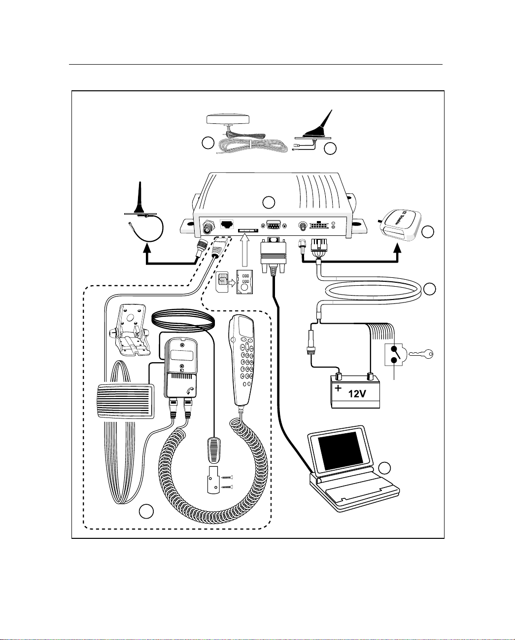
Figure 1.1 illustrates the CrossCheck GSM System Accessories.
CrossCheck GSM mobile unit
1
Voice Upgrade Kit including:
2
a. Handset
b. Mounting bracket
c. Handset cradle
d. Hands-free microphone
e. Extension cable
f. External speaker
Power and discrete I/O cable
3
GPS antenna
4
Laptop (not available from Trimble)
5
Combo GSM/GPS antennas (not available from Trimble)
6
CrossCheck GSM Mobile Unit Operation Manual
6
Page 21
Combo PCS/GPS or GSM/GPS
Overview
1
GSM
Antenna
6
CrossCheck
1
6
GPS
Antenna
4
SIM
SIM
Carrier
Ignition
Sense
3
2
Figure 1.1 CrossCheck GSM System Access ories
CrossCheck GSM Mobile Unit Operation Manual
5
7
Page 22

Overview
1
CrossCheck GSM Applications
1.3
Trimble Mobile Posi tioning & Communica tion (MPC) g roup pro vides
you with the core products around which you can build systems and
applications for managing your transport and logistics assets.
MPC products address the need for an end-to-end solution. They
provide the building blocks at both ends of the asset management
system including the on-board units mounted in the vehicle and the
software installed at the fixed base station.
The on-board components are centered on the CrossCheck GSM
receiver. You can use the receiver as a standalone unit, or you can
interface it with e xterna l accessories and sensors to make i t function as
part of an on-board system.
Optional EchoRTX external units include:
• Mobile Data Terminal (MDT) to provide a driver interface to
exchange messages or generate manual event reports
• A handset for use where voice communication is required
You can use the Trimble FleetVision software package at the base
station, as a standalone fleet-management system, or as the
communications platform for an integrated system. FleetVision
features include:
• Event and alarm reporting
• Data handling
• Map displays, allowing you to view the positions of mobile
assets in real-time or replayed for analysis purposes
CrossCheck GSM Mobile Unit Operation Manual
8
Page 23

Global System for Mobile Communicati on s
1.4
Cellular mobile tel ephone syst ems are wid ely a v ailable throughout the
world. However, because cellular mobile telephone systems are
regulated at the national level, these systems are not generally
compatible with each other. To resolve the dilemma of being able to
communicate from almost anywhere, but only within your own
system, the European tel ec ommu nic at ion s operators—the Conference
of European Postal and Telecommunications Administration
(CEPT)—designed a new mobile telephone networ k. This network has
evolved into GSM, and CEPT has turned over management of GSM to
the European Technical Standards Institute (ETSI). GSM is the
predominant mobile communications system throughout Europe.
GSM is also widely available throughout the world.
The European GSM system operate s a t 90 0 MHz and 1800 MHz. The
the American GSM system operates at 1900 MHz.
Overview
1
1.4.1
GSM Cellular Phone System
The Global System for Mobil e (GSM) pro tocol of f ers a v ar iety of da ta
services that allow users to send and receive data at rates of up to
9600 bps. Data can be delivered over ISDN, Packet Switched or
Circuit Switched Data Networks (PSDN or CSDN) and via the Short
Message Service (SMS).
SMS is a store-and-forward service for the bi-directional exchange of
alphanumeric messages of up to 160 characters.
Architecture of the GSM network
An Automatic Vehicle Location (AVL) or Asset Management System
based on GSM consists of several distinct components.
The Crosscheck GSM is th e mobil e u nit that is installed in the vehicl e
and contains the Subscriber Identity Module (SIM). The SIM card
contains a unique International Mobile Subscribe r Identity (IMSI)
number. This enables the network to identify the user and therefore
allow the termin al to have access to specific, subscriber services .
CrossCheck GSM Mobile Unit Operation Manual
9
Page 24

Overview
1
The GSM cloud (shown in Figure 1.2) is made up of two sections:
• The Base Station Subsystem that controls the radio link with the
mobiles through local cells
• The Network Subsystem that controls the switching of calls
between the network users, mobile to mobile, and between
mobile and fixed lines
The Network Subsystem st ores all administrative informa tion
including the current cell being used by the mobile unit which allows
call routing and the roaming ability of GSM. An important feature of
GSM is this ability to move across international and network borders,
a feature that is described as “roaming.” If arrangements have been
made with the service provider, the SIM card will be enabled for
roaming.
• Mobile Station (MS)
– The CrossCheck GSM includes a radio transmitter,
receiver and voice encoder, decoder. The optional Voice
Upgrade Kit includes a handset.
– Subscriber Identity Module (SIM) – an electronic card
containing a computer chip. The chip contains the
subscriber information and operating system parameters.
SIMs provide authentication, encryption, information
storage, and subscriber account protection services
(including Personal Identity Number or PIN, and Pin
Unblocking Key or PUK). GSM users can move the SIM
from one CrossCheck GSM to another.
• Other network components (part of the GSM network)
– Voicemail System (VMS) – deliv ers message s and pages to
GSM users.
– Short Message Service Center (SMSC) – delivers text
messages (up to 160 characters) to GSM users.
CrossCheck GSM Mobile Unit Operation Manual
10
Page 25
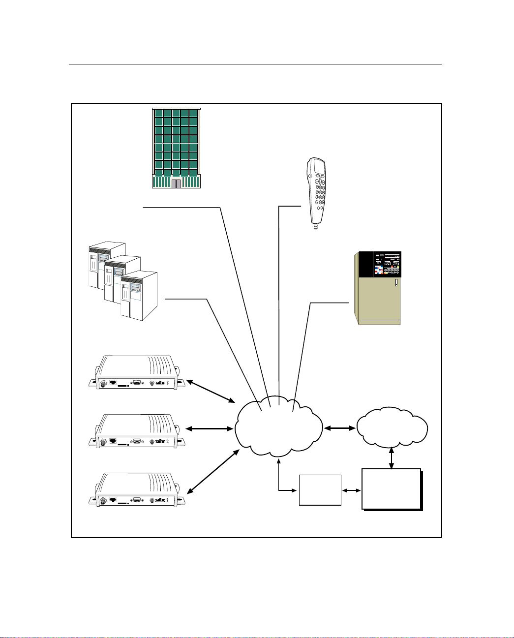
Figure 1.2 illustrates the GSM cellular network topology.
Overview
1
Operations and
Maintenance Center
CrossCheck GSM
CrossCheck GSM
CrossCheck GSM
Network
Subsystem
Mobile
Station
GSM Network
Operations
Subsystem
GSM
Modem
PSTN/ISDN
Base Station
Computer
Mobile V ehicles
Figure 1.2 GSM Cellular Network Topology
CrossCheck GS M M ob ile U nit O pe r ation Manual
11
Page 26

Overview
1
The Global Positioning System
1.5
The Global Positioning System (GPS ) is a satellite-based navigation
system operated and maintained by the U.S. Department of Defense.
GPS consists of a constellation of 24 satellites providing world-wide,
24-hour, three-dimensional (3D) coverage. Although originally
conceived for military needs, GPS has a broad array of civilian
applications including timing, surveying, fleet management, marine,
land, aviation, and vehicle navigation.
GPS is the most accurate technology available for navigation. As a
satellite-based system, GPS is immune from the limitations of landbased systems, which have limited coverage and whose accuracy
varies with geographic location and, even under ideal conditions,
cannot compare with GPS.
By computing the distance to GPS satellites orbiting the earth, a GPS
receiver can calculate an accurate position. This process is called
satellite ranging. GPS receivers can also provide precise time, speed,
and course measurements which are important for vehicle mobile
positioning and communications applications.
GPS Receiver
1.6
The CrossCheck GSM includes an advanced GPS receiver, which
provides the pos it io n, course, speed and time information requir ed f or
AVL and fleet mana gement applications. A brief overv iew of the GPS
receiver’s architecture and operation is provided below.
The CrossCheck GSM’s GPS receiver features an eight-channel
digital signal processor (DSP) which operates at the GPS L1
frequency (1575.42 MHz) and processes the Coarse/Acquisition
(C/A) code portion of the GPS signal. The RF and digital signal
processing components of the GPS module are custom ASICs
designed by Trimble.
CrossCheck GSM Mobile Unit Operation Manual
12
Page 27

GSM Operation
1.7
At power up, the Cros sCheck GSM automatically searches for a GSM
network using a set of tables on the SIM card to determine which
GSM network the phone should try to reach. These tables are the
Public Land Mobile Network (PLMN) tables and each GSM network
has its own uni que PLMN number . Thi s number is the Mobile Country
Code (MCC) and the Mobile Network Code (MNC), which are also
the first numbers of the subscriber’s IMSI. (The IMSI is the MCC,
plus the MNC, plus the MSIN.)
The PLMN table finds either the subscriber’s home network or a
network that will allo w service , and regi sters to the netw ork consis tent
with the handset. The responding network’s Mobile Switching Center
(MSC) passes this request for service to the Visitor Location Register
(VLR). If the VLR has information about thi s IMSI, then it passes the
request to the authentication center. If the VLR cannot find any
information on this IMSI, it must pass the request to the HLR and get
approval before passing on the request.
Once the VLR has approval to grant the request for service, it knows
the user identity, what features are authorized, and the authentication
codes. The VLR then passes the request back to the MSC for routing
to the number being called.
Overview
1
If the number being called is a l and-based numb er , the MSC passes the
call to the Public Switched Telephone Network (P STN) for
connection. If the number being called is another mobile number, the
MSC repeats the process described above to locate the number being
dialed. Depending on se rvice s suppo rted, the call will be ans wered, b e
routed to voicemail, be intercepted by a live answering service, or
simply time out with the message that the number being dialed is not
available. In any case, the transmission is digital and encrypted so
information cannot be intercepted easily.
CrossCheck GS M M ob ile U nit O pe r ation Manual
13
Page 28

Overview
1
CrossCheck GSM Mobile Unit Operation Manual
14
Page 29

CHAPTER
2
Installation
In this chapter:
■
Introduction
■
Installing the CrossCheck GSM Mobile Unit
■
CrossCheck GSM Connections
■
Inspecting and Unpacking the Shipment
■
Installer Supplied Part s
■
Mounting the CrossCheck GSM
■
Choosing the GPS Antenna Mounting Location
■
Routing the GPS Antenna Cable
■
Choosing a GSM Antenna Mounting Location
■
Connecting the Power and I/O Cable
■
Connecti ng a Co m pu t er or Mo bi le D at a Te rminal with the Serial I/O C a ble
■
CrossCheck GSM Power
■
Installing the CrossCheck GSM Voice Upgrade Kit
■
Choosing a Location for the Microphone
■
The Subscriber Identity Module (SIM)
2
Page 30

Installation
2
Introduction
2.1
This chapter presents instructions for installing the CrossCheck GSM
mobile unit in a vehicle.
Installing the CrossCheck GSM Mobile Unit
2.2
The CrossCheck GSM mobile unit can be installed before or after
configuring its IQEventEngine (IQEE) firmware. For example, you
might want to configure all of the units for a fleet of vehicles prior to
installation. If you pref er to configure the CrossCheck GSM unit f i rs t,
read Chapter 3, Configur ation, befor e installing t he CrossCheck GSM.
Note – If you plan to install the CrossCheck GSM receiver before
configuring the unit, be sure to leave adequate clearance to the
MDT/Aux port and other connectors. Adequate clear ance must e xist to
connect a laptop or Mobile Data Device to the unit, and you must be
able to read the LED indicators if troubleshooting is required.
CrossCheck GSM Mobile Unit Operation Manual
16
Page 31

CrossCheck GSM Connections
2.3
This section describes the CrossCheck GSM component connections.
Figure 2.1 shows the CrossCheck GSM connections.
2
1
3
Antenna
1
Mini-UHF receptacle for CrossCheck 900/1800
TNC receptacle for CrossCheck 1900
Hands-free cradle
2
SIM slot
3
MDT/Aux
4
GPS Antenna
5
Power and Discrete I/O
6
Installation
4
5
6
2
Figure 2.1 CrossCheck GSM Connection s
2.3.1
GSM Antenna
The CrossCheck 900/1800 uses a mini-UHF connector for the GSM
antenna. The CrossCheck 1900 uses a TNC connector for the GSM
antenna. For more information, see Appendix A.
CrossCheck GS M M ob ile U nit O pe r ation Manual
17
Page 32

Installation
2
2.3.2
Power and Discrete I/O Pinout
Table 2.1 lists how the power and discrete I/O cable carries signals.
Table 2.1 Power and Discrete I/O Pinout
Pin Signal Function
1V
2 GND Ground
3 CHAS Chassis Ground
4 GND Ground
5 IGN Input: Ignition Sense
6 IP3 Discrete Input 3
7 IP2 Discrete Input 2
8 XP2 Discrete Output 2
9 IP1 Discrete Input 1
10 XP1 Discrete Output 1
11 IP0 Discrete Input 0
12 XP0 Discrete Output 0
BATT
Input: Power 9–32V
Figure 2.2 illustrates the power and discrete I/O pinout.
12108642
1197531
Figure 2.2 Power and Discrete I/O Pinout
CrossCheck GSM Mobile Unit Operation Manual
18
Page 33

Installation
2
2.3.3
2.3.4
GPS Antenna
The GPS antenna uses an SMA female connector. For more
information, see Appendix A, Table A.4.
MDT/Aux Port
Figure 2.3 illustrates the MDT port pi n confi guration, a sta ndard 9-pin
DCE configuration.
12345
6789
Figure 2.3 MDT/Aux Pinout
Table 2.2 shows the MDT connector pinout.
Table 2.2 MDT Connector Pinout
Pin # Signal Connection
1 DCD Output: Carrier Detect
2 RxD Output: Serial Data
3 TxD Input: Serial Data
4 DTR Input: Data Terminal Ready
5 GND Ground
6 DSR Output: Data Set Ready
7 RTS Input: Request to Send
8 CTS Output: Clear to Send
9 N/A Output: Always inactive (not supported)
CrossCheck GS M M ob ile U nit O pe r ation Manual
19
Page 34

Installation
2
Inspecting and Unpacking the Shipment
2.4
The CrossCheck GSM may be shipped in one or more cartons,
depending on the number of units and the options ordered with the
shipment. Before opening the shipping containers, inspect the cartons
for punctures or damage and immediately report any damage to the
shipping carrier. Then open the shipping cartons individually and
check their contents against the packing slip.
Table 2.3 identifies the CrossCheck GSMs and bundles and the
included components.
Table 2.3 CrossCheck GSM Units and Bundles
Part No. Description
43455-00 CrossCheck GSM 900/1800 Mobile Unit (includes GPS
antenna, power and I/O cable, manual, hands et quick
reference, and the Voice Upgrade Kit).
43455-10 CrossCheck GSM 900/1800 Mobile Unit 10-Unit Bundle
(includes 10 CrossCheck GSMs without GPS antennas or
accessories).
43455-01 CrossCheck GSM 1900 Mobile Unit (includes GPS antenna,
power and I/O cable, manual, handset quick reference, and
the Voice Upgrade Kit).
43455-11 CrossChec k GS M 1900 Mobile Unit 10-Unit Bundle
10 CrossCheck GSMs without GPS antennas or
accessories).
(includes
Additional cartons may be included in the shipment for GPS and
cellular antennas, interface cables, and Voice Upgrade Kit options.
For a complete listing of CrossCheck GSM and component part
numbers, see CrossCheck GSM Part Numbers on page 121.
CrossCheck GSM Mobile Unit Operation Manual
20
Page 35

Installer Supplied Parts
2.5
The installer must supply the following parts:
• Mounting fasteners for the CrossCheck GSM.
• Fasteners for mounting the GPS antenna if the antenna is the
bulkhead type.
• Cable ties for securing cables to the vehicle.
• Any special connectors and adapters required to connect
interface devices and power leads. The power and I/O cable is
supplied only with the CrossCheck GSM 900/1800
PN 43455-00 and CrossCheck GSM 1900 PN 43455-01.
• Subscriber Identity Module (SIM) cards.
• GSM antenna.
• GPS antenna (supplied only with the CrossCheck GSM
PN 43455-00 and 43455-01).
Note – The required accessories are not supplied with the 10-Unit
Bundles.
Installation
2
Mounting the CrossCheck GSM
2.6
The CrossCheck GSM can be installed inside any type of vehicle and
in any orientat ion. It can be in stalled i n an enclosed co mpartment or in
a location with limited accessibility, as long as the environmental
specifications are maintained to ensure reliable operation. For
example, the CrossCheck GSM can be installed on the floor under a
seat or on a wall behind a seat.
Note – The CrossCheck GSM cannot be installed inside the engine
compartment, wheel well, chassis, or on any exterior surface of the
vehicle.
CrossCheck GS M M ob ile U nit O pe r ation Manual
21
Page 36

Installation
2
Choose a location for the CrossCheck GSM w hich allows for
conv enie nt routing and connectio n of the antenn a and inte rface cables,
and which has access to a power source. When selecting a mounting
location, consider the specifications listed in Appendix A, Table A.8,
and avoid the following hazards:
• Direct exposure to weather
• Excessive heat (exhaust manifolds)
• Excessive cold (refrigeration units)
• High-vibration areas (engine compartment, transmission)
• Corrosive fluids and gases (acids, petroleum products)
• Direct expos ure to water (The CrossCheck GSM is no t
waterproof.)
To mount the CrossCheck GSM:
1. Choose the mounting location.
The CrossCheck GSM can be mounted horizontally, vertically,
or in any convenient orientation. During normal system
operation, the user does not need to see the CrossCheck GSM
LED indicators. However, the ability to see the LED indicators
is a definite advantage when troubleshooting the unit.
The integral mounting flange is designed to secure the
CrossCheck GSM to a flat surfac e. The flange has fou r holes for
securing the unit with fasteners.
2. Use se lf -t apping screws or machine screws to se cur e the unit to
the mounting surface.
,
CrossCheck GSM Mobile Unit Operation Manual
22
Caution –
tightening the mounting screws can cause the plastic to crack. Use
washers sized small enough that they do not tighten down on the
plastic cover of the CrossCheck GSM when the mounting screws are
secured. Tightening screws without using washers can lead to
compressing, cracking, or deforming the mounting surface.
Over-stressing the plastic mounting surface when
Page 37

Figure 2.4 shows the mounting dimensions.
205.5
Figure 2.4 CrossCheck GSM Mounting Dimensions (in millimeters)
Installation
4.8
69.9
2
The installer must provide an appropriate selection of fasteners
to secure the CrossCheck GSM to the mounting surface.
a. When using self-tapping screws, select an appropriate size
and length for the mounting surface. The hole size leaves
some allowance for holes drilled slightly off center from
the specified dimensions.
b. When using machine screws:
Select a screw length which e xtends a s afe dist ance be yond
the mounting surface.
Secure the screw with a washer and nut. Lock washers are
recommended to prevent vehicle vibration from loosening
the fasteners.
In general, Trimble recommends the use of number m3.5
(or number 6) pan - head machi ne screws.
CrossCheck GS M M ob ile U nit O pe r ation Manual
23
Page 38

Installation
2
2.6.1
Connecting CrossCheck GSM to the Vehicle Chassis
For proper operation, the aluminum chassis of the CrossCheck GSM
must be connected electr ic ally ( grounde d) to t he chass is of t he v ehi cle
on which it installed. This can be accomplished in two ways:
• Direct connection through metal screws (preferred)
• Connection through the chassis ground wire
Direct Connection through Mounting Screws
To mount the CrossCheck GSM mobile unit on a metal surface that is
permanently attached to the vehicle chassis (for example, the base of
the trunk, or a mounting plate that is permanently attached to the
chassis using metal screws):
1. Fasten down the CrossCheck GSM mobile unit using metal
screws driven through the metal tabs on the sides of the unit.
2. Use star washers to ensure a reliable electrical contact to the
metal tabs.
3. Make sure the screws are tight, an d tha t t h ey make contact both
with the metal on the CrossCheck GSM and with the vehicle
chassis.
Note – If this direct connection through mounting screws method is
used for chassis connection, then the chassis ground (pin 3 on the
power and discrete I/O connector) on the Cros sCheck GSM should be
left unconnected.
CrossCheck GSM Mobile Unit Operation Manual
24
Page 39

Connection through the Chassis Ground Wire
If the CrossCheck GSM cannot be moun ted directly on a metal surf ace
that is attached to the vehicle, then use the chassis ground wire (pin 3
on the power and discrete I/O connector) to make electrical contact to
the vehicle chassis:
1. Use a wire with gauge of at least 18 AWG to connect the
CrossCheck GSM power connector to the vehicle chassis.
2. Use a metal screw with a star washer to ensure a reliable
electrical contact to the vehicle chassis.
3. Keep the wire length as short as possible by selecting a
connection point in the vehicle chassis that is close to the
CrossCheck GSM.
Choosing the GPS Antenna Mounting Location
2.7
Antenna location is crit ical for optim um GPS perfo rmance. Wh en
choosing a location for the GPS antenna, consider these guidelines:
Installation
2
• The antenna has an unobstructed view of the sky.
• The antenna is safe from damage during normal vehicle
operation and maintenance.
• The antenna is not shielded from satellite signals by metal
objects or other impenetrable materials.
GPS signals can penetrate plastic, glass and tinted glass (except
metalized glass), fiberglass, and plexiglass materials as long as the
surface is re lati v ely dr y. GPS satellite signal s do not pe netrate metal o r
dense wood.
Since GPS satellite signals can penetrate plastic, fiberglass, and glass,
the GPS antenna can also be installed on a dashboard under a sloped
windshield (if the windshield is not metallized) or under a plastic
fender or bumper. These alternative locations are likely to offer less
satellite co verage, s ince the meta l components of the vehic le shield the
antenna from portions of the sky.
CrossCheck GS M M ob ile U nit O pe r ation Manual
25
Page 40

Installation
2
,
Caution –
windshield, such as those used in some vehicles for window
de-fogging or de-icing systems. However, the GPS antenna can be
mounted under a tinted-glass windshield.
Disclaimer –
GPS antennas sold by Trimble and may not apply to third-party
products. There are many other GPS antennas available on the
market which may or may not be compatible with the CrossCheck
GSM, including combined GPS/GSM cellular antenna solutions which
have not yet been tested and certified by Trimble.
Do not mount the GPS antenna under a metalized glass
The instructions included in this section apply to the
Additional guidelines to follow include:
• Mount the antenna in a horizontal position (see Figure 2.5)
facing the sky.
• If the antenna must be located in the vicinity of other antennas
(radio, cellular phone), locate the GPS antenna at least 46 cm
(approximately 18 in.) away.
• Avoid areas of high vibration (for example, engine hoods).
• For permanent installations, choose a location with access both
above and below the antenna mounting surface. This access is
required for installing fasteners and for routing the antenna
cable.
Note – The standard length of magnetic-mount and bulkhead-mount
GPS antenna cables supplied by Trimble is 5 m (appr oximate ly 16 ft.).
Longer bulkhead-mount antenna cables can be prepared by the
installer using the guidelines presented in Appendix A.
CrossCheck GSM Mobile Unit Operation Manual
26
Page 41

Installation
Figure 2.5 shows typical antenna-mounting locations for an
automobile.
2
Best Performance
Figure 2.5 Antenna Mounting Locations for Automobile
Reduced Performance
CrossCheck GS M M ob ile U nit O pe r ation Manual
27
Page 42

Installation
2
Figure 2.6 shows the typical antenna mounting locations for a van.
1
Best Performance the GPS antenna
should be mounted in a location with
a clear unobstructed view of the sky
1
3
Figure 2.6 Antenna Mounting Locations for Van
2
Reduced Performance - avoid locations
where the antenna does not have a
clear unobstructed view of the sky
3
Unacceptable Locations
.
2
CrossCheck GSM Mobile Unit Operation Manual
28
Page 43

Installation
The antenna can be mount ed under a fiberglass wi nd def le ctor such as
those used on conventional and cabover trucks (see Figure 2.7). Make
sure the wind deflector is not painted with a metallic finish.
Note: Must be
fiberglass
Figure 2.7 Antenna Mounted under Fiberglass Canopy
2
Note – The GPS antenna may be subject to performance degradation
when covered by a heavy layer of snow or ice. If these are typical
conditions for your application, mount the antenna in an accessible
location so snow can be easily removed.
The CrossCheck GSM can receive GPS signals from one of two typ es
of optional Miniature BulkHead GPS antennas or a Miniature
Magnetic GP S antenna, all available from Trimble. Follow the
applicable procedure (below) to mount the GPS antenna.
CrossCheck GS M M ob ile U nit O pe r ation Manual
29
Page 44

Installation
2
2.7.1
Miniature BulkHead GPS Antenna with Flange
(P/N 31192-00)
Two cables are available for the Miniature Bulkhead Antenna
with Flange:
• A straight TNC-Plug-to-SMA-Plug antenna cable (P/N 36107)
• A right-angle TNC-Plug-to-straight SMA-Plug antenna cable
(P/N 36106)
For more infor mation, see Appendix A.
Figure 2.8 shows the Miniature Bulkhead GPS antenna mounting.
Mounting Lug
Gasket
Figure 2.8 Miniature Bulkhead GPS Antenna with Flange (P/N 31192-00)
CrossCheck GSM Mobile Unit Operation Manual
30
Cable
Mounting hardware.
Only two of four sets
shown for clarity.
Page 45

Installation
To mount the Miniature Bulkhead GPS Antenna with Flange:
1. Drill holes in the mounting surface using the antenna mounting
template shown in Figure 2.9.
19 mm
(0.75 in)
7.6 cm
(3.0 in)
3.8 mm
(0.15 in)
Figure 2.9 Mounting Hole Dimensions
2
2. Sl ip the an tenn a thro ugh the la r ger hol e in the center of the ho le
pattern and rotate the ant enna unt il the four hol es in t he an tenna
mounting flange are aligned to the hole circle.
3. Sec ure the antenna with the four s cre ws, l ock was hers, and nuts .
4. Connect the TNC connector on the antenna cable to the TNC
connector on the antenna.
5. Route the cable to the CrossCheck GSM mounting location.
Use cable ties to secure the cable along the routing path.
6. Connect the cable to the GPS antenna connector on the front of
the CrossCheck GSM.
For detailed cable routing guidelines, see Routing the GPS Antenna
Cable on page 35.
CrossCheck GS M M ob ile U nit O pe r ation Manual
31
Page 46

Installation
2
2.7.2
Miniature Bulkhead GPS Antenna without Flange
(P/N 32434)
Two cables are available for the Miniature Bulkhead Antenna
without Flange:
• A straight TNC-Plug-to-SMA-Plug antenna cable (P/N 36107)
• A right-angle TNC-Plug-to-straight-SMA-Plug antenna cable
(P/N 36106)
For more infor mation, see Appendix A.
Check the metal thickness at the mounting location before drill ing the
mounting hole. The bulkhead mount on the antenna is designed to
attach to metal surfaces with a thickness of 48 mm (0.1875 in.) or less.
Gasket
Sheet Metal
Figure 2.10 Miniature Bulkhead GPS Antenna without Flange (P/N 32434)
CrossCheck GSM Mobile Unit Operation Manual
32
Metal Washer
Mounting Nut
Jam Nut
Page 47

Installation
To mount the antenna:
1. Choose the antenna mounting location (see Choosing the GPS
Antenna Mounting Location on page 25).
2. Drill a 19 mm (0.75 in.) hole at the mounting location.
3. Remove the large nut from the bottom of the antenna.
4. Mount the gasket as shown in Figure 2.10.
5. Slip the antenna through the mounting hole, and secure it with
the large nut.
6. Connect the antenna cable as shown in Figure 2.10.
7. Route the cable to the CrossCheck GSM mounting location
8. Connect the cable to the GPS Antenna connector.
9. Use cable ties to secure the cable along the routing path.
For detailed cable routing guidelines, see Routing the GPS Antenna
Cable on page 35.
2
CrossCheck GS M M ob ile U nit O pe r ation Manual
33
Page 48

Installation
2
2.7.3
Miniature Magnetic GPS Antenna (P/N 40767-40)
The Miniature Magnetic Antenna features a magnetic mount for
attaching the unit to ferrous metal surfaces and an integr al 5-m cable
with SMA connector.
,
Caution –
the antenna end of the cable and is not recommended for permanent
installations.
Figure 2.11 Miniature Magnetic GPS Antenna
To mount the Magnetic GPS Antenna:
1. Choose the antenna mounting location (see Choosing the GPS
The magnetic-mount antenna cable has no strain relief at
Antenna Mounting Location on page 25).
2. Mount the antenna to a ferrous surface.
The antenna can be mounted on the exterior of the vehicle or
inside the vehicle.
3. Route the antenna cable.
The antenna features a permanent antenna cable which must be
routed to the location where the CrossCheck GSM is mounted.
,
CrossCheck GSM Mobile Unit Operation Manual
34
Caution –
environment. Wind could cause damage to the cable; use tie wraps to
secure the cable along its route.
See Routing the GPS Antenna Cable in the next section.
The magnetic-mount antenna cable is exposed to the
Page 49

Routing the GPS Antenna Cable
2.8
The Magnetic GPS Antenna has an integral antenna cable, and the
Miniature Bulkhead GPS Antennas have a separate 5-m
(approximately 16-ft.) cable.
If you are using one of the Miniature Bulkhead GPS Antennas, attach
the antenna cable to the connector on the base of the antenna prior to
routing the cable.
When routing the cable, s tart at the ante nna and choos e the most direc t
path to the CrossCheck GSM while avoiding the following hazards:
• Make sure that at least 5.1 cm (2 in.) of clearance exists
between the CrossCheck GSM’s antenna connector and the
nearest ob stacle.
• Make all cable bends, especially the bend at the SMA strain
relief to the Antenna connector, with at least 1.3 cm (0.5-in.)
bend radius.
• Provide an adequ ate servi ce loop when routi ng the cabl e around
vehicle hinges to ensure that the cable is not pinched when a
hinged door opens or closes.
Installation
2
• Make sure that the coa x cabl e is not rou ted through areas whe re
vehicle movement can abrade the cable surface.
• Never coil the excess antenna cable, particularly the Magnetic
GPS antenna cable. A coiled cable can act as an antenna and
may receive interference.
• Protect cables from exposure to corrosive fluids.
Once the cable is routed and secured, attach the cable to the
CrossCheck GSM GPS (SMA) connector.
CrossCheck GS M M ob ile U nit O pe r ation Manual
35
Page 50

Installation
2
Choosing a GSM Antenn a Mounting Location
2.9
Cellular antenna placement is important, although not as critical as
GPS antenna placement. Mount t he cellular whip antenna in a ver ti cal
orientation in a location where it is safe from damage during normal
vehicle operation and maintenance.
Note – Automated vehicle washes may damage poorly placed
cellular antennas.
If you are installi ng multiple an tennas, main tain a separa tion of at l east
46 cm (approximately 18 in.) between the cellular (or other) and GPS
antennas (see Figure 2.12). If you are using a combination
GPS/cellular antenna, maintain a separation of at least 46 cm
(approximately 18 in.) between the combination antenna and any
other antennas.
Figure 2.12 illustrates the suggested distance between antenna
locations.
GPS
Antenna
Figure 2.12 Distance Between Antenna Locations
CrossCheck GSM Mobile Unit Operation Manual
36
46cm
(18 in)
minimum
Cellular
Antenna
Page 51

Installation
In general, the larger the separation, the less chance of interference.
For permanent antenna installations, choose a location with access
both above and below the antenna-mounting surface. This access is
required for installing fasteners and for routing the antenna cable.
Cellular phone dealers and installers are experts on cellular antenna
placement. For some installations, the installer can substitute a glassmount antenna as long as it conforms to the requirements listed in
Appendix A.
2
CrossCheck GS M M ob ile U nit O pe r ation Manual
37
Page 52

Installation
2
2.9.1
Routing the GSM Antenna Cable
The next step in the installation process is routing and connecting the
antenna cable to the CrossCheck GSM.
,
Caution –
operations is not permitted.
When routing the cable, s tart at the ante nna and choos e the most direc t
path to the CrossCheck GSM. Avoid the following hazards:
• Sharp bends or kinks in the cable.
• Excessiv e heat .
• Exposure to corrosive fluids.
• Excess coils in the antenna cable, particularly the cellular
• Pinching the cable in a hinged d oor . Pro vide an adeq uate servic e
• Vehicle movement that might cause cable damage. Make sure
Use of the CrossCheck GSM in portable (hand-carried)
antenna cable. A coiled cable can act as an antenna and may
receive interference.
loop when routing the cable around vehicle hinges.
that the coax cable is not routed through areas where vehicle
movement can ab rade the cab le surface.
• Exposure to environmental damage. If your cellular antenna
cable is exposed to the environment, use tie wraps to secure the
cellular antenna cable along its route to prevent wind damage.
,
CrossCheck GSM Mobile Unit Operation Manual
38
Caution –
8 in.) must be maintained between the radiating GSM antenna and
the user for this device to satisfy the RF Exposure requirements of the
FCC. For fixed-mount operation, the antenna co-location
requirements of Section 1.1307(b)(3) of the FCC rules must be
satisfied. For fixed-mount operation, the maximum gain of the antenna
must not exceed 7 dBi. For mobile operation, the maximum gain of the
GSM antenna must not exceed 3 dBi.
A minimum separation distance of 20 cm (approximately
Page 53

Connecting the Power and I/O Cable
2.10
Use the flexible power and I/O cable (P/N 40358) to connect power
and a variety of input and output peripherals to the CrossCheck GSM
(see Figure 2.13).
2
4
8
10 12
6
9
57
3
1
Front View
Side View
11
Connector
Molex Micro-Fit 3.0 12-Pin
Molex P/N 43025-1200
Molex female
templated contact
Molex P/N 43030-0001
Installation
Pins
2
36
Batt. GND
Chassis GND
AGC 2A@250V
Fast Acting
6
V
batt
GND
IGN
IP3
IP2
XP2
IP1
XP1
IP0
XP0
Figure 2.13 Power and I/O Cable
The power and I/O cable is 91 cm (3 ft.) long with 12 wire leads.
It connects to the CrossCheck GSM’s I/O port.
1 Vbatt Red Input Power 9-32V
2 GND Black Batt. GND
3 GND Green Chassis GND
4 GND Blk/White GND
5 IGN White Ignition Sense Input
6 IP3 Blue Input 3
7 IP2 Purple Input 2
8 XP2 Orange Discrete Output 2
9 IP1 Yellow Input 1
10 XP1 Gray Discrete Output 1
11 IP0 Purple/White Input 0
12 XP0 Brown Discrete Output 0
CrossCheck GS M M ob ile U nit O pe r ation Manual
39
Page 54

Installation
2
Table 2.4 provides pinout information for the I/O cable. Each of the
connections is described in Table 2.4.
Table 2.4 Power and I/O Cable Pinout
Pin # Signal Function
1V
2 GND Ground
3 CHAS Chassis Ground
4 GND Ground
5 IGN Input: Ignition Sense
6 IP3 Discrete Input 3
7 IP2 Discrete Input 2
8 XP2 Discrete Output 2
9 IP1 Discrete Input 1
10 XP1 Discrete Output 1
11 IP0 Discrete Input 0
12 XPO Discrete Output 0
Batt
Input: Power 9–32V
If you want to mak e y our o wn po we r and I /O cab le, re fer t o Figur e 2.2
on page 18 for the spe cif i catio ns for the cabl e conne ct ors ( Mole x
43025-1200) and contacts (Molex P/N 43030-0001).
You must include an AGC 2A@250V fast-acting fuse connected to
Pin 1.
CrossCheck GSM Mobile Unit Operation Manual
40
®
P/N
Page 55

Installation
2
2.10.1
Inputs (IP0 to IP3)
The CrossCheck GSM supports four discrete inputs. The circuit
diagram is shown in Figure 2.14.
3.3V/10m/A
330K
Input
Figure 2.14 Input Circuit Diagram
Input Logic High:
Input Logic Low:
Input Current
(Max)
Input Protection:
3K
470pf
Open circuit or V
< 0.6 VDC
V
in
The inputs must remain in either state for at least
200 milliseconds before the CrossCheck GSM
detects the input.
< 3 milliamps
I
in
1 milliamp is typical at 12 VDC.
Protected up to at least VBatt continuous
100K
1.0µF
> 2.4 VDC
in
To logic
Each input floats to a logic-high state (inactive) when left open.
Grounding an input causes a logi c- low state (active). The CrossCheck
GSM can be configured to detect either logic-high or logic-low states
at the inputs whenever the unit is powered on.
CrossCheck GS M M ob ile U nit O pe r ation Manual
41
Page 56

Installation
2
Note – When the CrossCheck GSM is powered off or in Power
Management mode, it can only detect a logic-low (grounded) input.
The discrete inputs ar e compat ible wi th prop er ly conne cted r elays a nd
switches or with sta nda rd 3.3 VDC l ogi c l evels. A properly connecte d
relay or switch allows the input to float high in one position and
grounds the input in the other position.
The input must be held in a particular logic state for at least 200 msec
(configurable up to 1 sec) so the CrossCheck GSM can detect it.
2.10.2
Outputs (XP0 to XP2)
The CrossCheck GSM features three discrete outputs (XP0-XP2) for
driving external devices such as relays.
• When inactiv e (use stat e), the discr ete outputs ar e tied to v ehicle
battery voltage (nominally 12 VDC) through a 15 kOhm
resistor.
• When active, the outputs are shorted to ground through a
bipolar junction transistor. In the active (low) state, the outputs
can sink up to 200 milliamps.
CrossCheck GSM Mobile Unit Operation Manual
42
Page 57

Figure 2.15 shows a diagram of a discrete output.
Vbatt
Installation
2
15K
0.2A
Output
36V
470pf
Figure 2.15 Output Circuit Diagram
Output Inactive:
Output Active:
Output Protection:
Output Sink Current
Capability
15 kOhms through V
Tied to ground through a saturated bipolar
junction transistor, V
200 milliamps; V
10 milliamps
Protected against direct shorts to ground
Up to 200 milliamps
0.01uF
out
< 0.5 VDC at
out
vehicle-battery
1.5 VDC at
For more information about discrete outputs, refer to the
TAIP/IQEventEngine Reference Manual, Digital Inputs and Outputs.
CrossCheck GS M M ob ile U nit O pe r ation Manual
43
Page 58

Installation
2
Connecting a Computer or Mobile Data Terminal
2.11
with the Serial I/O Cable
The D-9 connector is an RS-232 (receptacle) DCE (Data
Communication Equipment) serial port, making it compatible with
most personal computers and Mobile Data Devices.
You can configure the MDT/Aux port with the TAIP MT command.
(For more information on TAIP commands, refer to the
TAIP/IQEventEngine Reference Manual.)
The MDT port supports the following modes:
• Normal – Supports any combination of TAIP, TSIP, and
NMEA protocols.
• PAD – All input is converted into TAIP TX messages, all output
is text stripped from TX messages.
• AT – Traffic consists of AT commands and data from the MDT
device to GSM, and GSM responses to the MDT device.
±
The MDT inputs (Rx) accept
less than –3 VDC (typical). A high-input signal is greater than
+3 VDC. The MDT outputs (Tx) range from
depending on the load.
3to ±15 VDC. A low-input signal is
±
5 VDC to ±8 VDC,
Note – During normal operation, the MDT/Aux service port
communicates with a PC or Mobile Data De vice us ing TAIP messages
at 9600 bps, 8-N-1, and no flow control. The baud rate and other
communications parameters can be set to match the PC or Mobile
Data Device settings. For more information, see Chapter 5 in this
manual and the TAI P/IQEventEngine Reference Manual.
CrossCheck GSM Mobile Unit Operation Manual
44
Page 59

Installation
Figure 2.16 shows the cable connections between a PC and the
CrossCheck GSM.
CrossCheck GSM
MDT/Aux Port
To Serial Port on Laptop
Serial I/O Cable
Straight - no null modem
2
Figure 2.16 PC to CrossCheck GSM Connections
CrossCheck GS M M ob ile U nit O pe r ation Manual
45
Page 60

Installation
2
CrossCheck GSM Power
2.12
The CrossCheck GSM operates on input voltages from 9–32 VDC.
The low-noise amplifier integrated on the GPS antenna draws power
from the CrossCheck GSM through the antenna cable. The
CrossCheck GSM does not require any special power-up or down
sequencing.
The CrossCheck GSM’s power circuitry is desig ned to prote ct the unit
from random power fluctuations and conditions. Input circuits protect
against transient voltage spikes found in most auto and truck
environments. An external fuse p rotects against excessive current.
For more information on the CrossCheck GSM power requirements,
see Appendix A.
CrossCheck GSM Mobile Unit Operation Manual
46
Page 61

Figure 2.17 illustrates the power and I/O cable.
2
4
8
10 12
6
11
9
57
3
1
Front View
Side View
Molex Micro-Fit 3.0 12-Pin
Installation
Connector
Molex P/N 43025-1200
Pins
Molex female
templated contact
Molex P/N 43030-0001
2
36
Batt. GND
Chassis GND
AGC 2A@250V
Fast Acting
6
V
batt
GND
IGN
IP3
IP2
XP2
IP1
XP1
IP0
XP0
Figure 2.17 Power and I/O Cable (P/N 40358)
Note – T r imbl e recommends installing the power and ground leads as
close to the battery as possible to ensure that the CrossCheck GSM is
connected to the cleanest possible source of power.
1 Vbatt Red Input Power 9-32V
2 GND Black Batt. GND
3 GND Green Chassis GND
4 GND Blk/White GND
5 IGN White Ignition Sense Input
6 IP3 Blue Input 3
7 IP2 Purple Input 2
8 XP2 Orange Discrete Output 2
9 IP1 Yellow Input 1
10 XP1 Gray Discrete Output 1
11 IP0 Purple/White Input 0
12 XP0 Brown Discrete Output 0
CrossCheck GS M M ob ile U nit O pe r ation Manual
47
Page 62

Installation
2
The CrossCheck GSM is protected against both input power overvoltage and reverse polarity. The primary power cable has a built-in
AGC 2A@250V fast-acting fuse. The DC ground line connects to the
vehicle’s DC ground. The ignitio n-sens e lead , if conn ected t o a sour ce
of ignition-switched battery voltage, senses when the vehicle’s
ignition is active. There are three connection options for connecting
the power, ground, and ignition-sense wires. These options are
described in the next three sections.
Note – The CrossCheck GSM (including the cellular phone) will
power down automatically when input voltage drops below 9 VDC or
exceeds 32 VDC. See the input power specification in Appendix A.
IQEventEngine signals for under - and over-v oltage ar e availabl e, with
default values of 9.5 VDC and 31.5 VDC, respectively. For
configurations, refer to the TAIP PM message description in the
TAIP/IQEventEngine Reference Manual.
2.12.1
Connections For Power Management
For the Power Management configuration, the CrossCheck GSM
operates and draw s po wer (1 50 milliamps nominal) continuously only
when the vehicle is running. When the ignition is off, the CrossCheck
GSM responds to the cha nge in the stat e of th e igni tion- sense lead a nd
goes to sleep (at programmed intervals), drawing reduced power
(< 10 milliamps).
When the IQEventEngine is configured for Power Management, the
CrossCheck GSM can be scheduled to:
• Wake up periodically, typically long enough to refresh its
GPS position then return to standby mode
• Wake up when triggered by an externa l signal
Therefore, even though the CrossCheck GSM is drawing power while
awake, its duty cycle is a fraction of what it would be under
Continuous Power, and battery life is extended.
CrossCheck GSM Mobile Unit Operation Manual
48
Page 63

Installation
Note – For the Power Management mode, make sure that the
Command parameter is set to A using the PM message. (For more
information, refer to PM Message in the TAIP/IQEventEngine
Reference Manual.) Power Management is disabled (Command
parameter is s et to D) by default which i s equival ent to t he Continuou s
Power mode.
Figure 2.18 illustrates the Power Management connections.
To
CrossCheck
GSM
Power and I/O
Cable
AGC 2A@250V
batt
Fast Acting
Red
V
2
BATT. GND
CHASSIS GND
GND
IGN
IP3
IP2
XP2
IP1
XP1
IP0
XP0
Black
Green
White
Figure 2.18 Power Management Connections
CrossCheck GS M M ob ile U nit O pe r ation Manual
49
Page 64

Installation
2
T o ins tall the po we r cable for use with the Po we r Managem ent fe ature :
1. Connect the primary power line to a nonswitched/continuous
source of DC power, such as the vehi cle’s batte ry.
2. Connect the ignition-sense line to ignition-switched battery
power so that this line is active when the ignition is on.
2.12.2
Continuous Power Connection (No Power Management)
For the Continuous Power configuration (see Figure 2.19), the
CrossCheck GSM operates an d dr aws power continuously, even when
the vehicle is not running:
• Without the Voice Upgrade Kit, 50 milliamps is typical.
• With the Voice Upgrade Kit, 325 milliamps is typical.
,
Caution –
GSM may drain a car battery in 1 to 3 weeks, depending on the
battery quality and remaining life span, and whether or not the vehicle
is operating during the entire time.
using this connection option.
automatically power off when the voltage drops below 9 VDC.
With the Continuous Power Configuration, the CrossCheck
Observe extreme care when
The CrossC heck GSM will
CrossCheck GSM Mobile Unit Operation Manual
50
Page 65

Figure 2.19 illustrates connections for Continuous Power.
To
CrossCheck
GSM
Power and I/O
Cable
AGC 2A@250V
batt
Fast Acting
Red
V
Installation
2
BATT. GND
CHASSIS GND
GND
IGN
IP3
IP2
XP2
IP1
XP1
IP0
XP0
Black
Green
White
Figure 2.19 Continuous Power Connections
To connect the power cable to Continuous Power:
1. Connect the primary power line.
2. Connect the ignition-sense line to a nonswitched/continuous
source of DC power, such as the vehi cle’s batte ry.
CrossCheck GS M M ob ile U nit O pe r ation Manual
51
Page 66

Installation
2
Installing the CrossCheck GSM Voice Upgrade Kit
2.13
The Voice Upgrade Kit (P/N 43456) includes the items shown in
Figure 2.20.
Fasteners
RJ-45 10-pin Extension Cable
Microphone
Handset Cradle
Figure 2.20 Vo ic e Upg r ade Kit Components
To perform the installation, use the following components from the
Voice Upgrade Kit:
• Handset
• Cradle Mounting Bracket
• 5-m (approximately 16-ft.) RJ-45 Extension Cable for
connecting to the CrossCheck GSM
Handset
External Speaker
Cradle Mounting
• Microphone
CrossCheck GSM Mobile Unit Operation Manual
52
Page 67

Installation
• Handset Cradle
• Mounting Fasteners
• External Speaker
As an example, Figure 2.21 shows the typical cable interconnection
scheme between a CrossCheck GSM mounted in a car trunk using the
RJ-45 Extension Cable.
2
Handset
and
Cradle
Microphone
Speaker
GPS
Antenna
CrossCheck
GSM
Cellular
Antenna
Figure 2.21 Typical Voice Upgrade Kit Installation for Car with the CrossCheck GSM Mounted
in Trunk
Installer-Supplied Components
The parts listed in Table 2.5 must be supplied by the installer.
Table 2.5 Items Supplied by Installer
Qty Item Supplied by Installer
1 Mounting S tand (if necessary)
varies Appropriate Screws for installing the Mounting Stand
CrossCheck GS M M ob ile U nit O pe r ation Manual
53
Page 68

Installation
2
Figure 2.22 illustrates the Voice Upgrade Kit installation.
a
a
Microphone
Figure 2. 22 Installation of the Voice Upgrade Kit
The following sections provide installation illustrations and
instructions for the Voice Upgrade Kit components.
a
Speaker Mounting Options
a
a
CrossCheck GSM Mobile Unit Operation Manual
54
Page 69

Installation
2
2.13.1
Mounting the Cradle Mounting Bracket
The Handset Cradle, Cradle Mounting Bracket, and fasteners are
included with the Voice Upgrade Kit. Figure 2.23 shows the assembly
of the Handset Cradle and the Cradle Mounting Bracket.
Microphone
Speaker
Figure 2.23 Cradle Mounting Bracket Assembly
CrossCheck GS M M ob ile U nit O pe r ation Manual
55
Page 70

Installation
2
The Cradle Mounting Bracket can be mounted on the vehicle
dashboard or at another location within easy reach for the driver.
To install the Cradle Mounting Bracket:
1. Choose an appropriate location to install the Cradle Mounting
Bracket, ensuring that the location meets these conditions:
– The material is firm enough to provide a stable mount.
– No hazards are in the w ay wh en dr iving in the self-tapping
screws (for example: wiring or fuel tank).
– The Cradle Mounting Bracket does not interfere with seat
travel or gear-shift movement.
– The handset is positioned for comfortable viewing.
– There is easy access to the handset from the driver’s seat.
Note – If a suitable mounting location cannot be found for the Cradle
Mounting Bracket, a 2-, 4-, or 6-in. pedestal mount, or a right-angle
swivel bracket and bracket adapter latch can be used.
2. Orient the base of the Cradle Mounting Bracket in the most
accessible direction for grasping the handset.
3. Use the holes in the Cradle Mounting Bracket as a hole drilling
template for marking holes at the mounting location.
4. Secure the Cradle Mounting Bracket t o the dash or oth er vehicl e
mounting location using the appropriate fasteners.
5. Insert the handset into the Handset Cradle and press down until
the handset snaps into the Cradle.
CrossCheck GSM Mobile Unit Operation Manual
56
Page 71

Installation
2
2.13.2
Mounting the External Speaker
Figure 2.24 illustrates how to mount the external speaker.
Speaker Mounting Options
Figure 2.24 Mounting the External Speaker
CrossCheck GS M M ob ile U nit O pe r ation Manual
57
Page 72

Installation
2
Two brackets are provided for mounting the speaker. To mount
the speaker:
1. Select the appropriate bracket for your application.
2. Screw the bracket to the dashboard.
3. Select the appropriate angle or fixed position for the speaker.
4. Tighten the screws.
2.13.3
Installing the Extension Cable
,
Caution –
cable for the 10-pin, RJ-45 Extension Cable. The 10-pin, RJ-45
Extension Cable is a 10-conductor cable, not an 8-conductor RJ-11
phone cable or a regular 8-pin RJ-45 LAN cable.
To install the extension cable:
1. Route the RJ-45 extension cable through the vehicle chassis to
2. Connect one end of the RJ-45 extension cabl e to the RJ-45 jack
Hands-Free Operation Considerations
For echo cancellat ion and hand s-fr ee operat ion, the CrossCheck GSM
has full-duplex , hands-free capability. This means that both parties in a
conversation can speak simultaneously, allowing for natural
conversation to take place. The listener can interrupt the speaker or
several people can speak into the hands-free microphone at the
same time.
Do not substitute an RJ-11, or regular RJ-45, extension
the CrossCheck GSM.
on the CrossCheck GSM and the o the r end to the RJ-45 jack on
the handset cradle.
CrossCheck GSM Mobile Unit Operation Manual
58
Page 73

Installation
In hands-free mode, the CrossCheck GSM uses an adaptive echocancellation algor it hm to prevent the sounds generated by the ext er n al
speaker from getting into the microphone and causing an echo on the
called phone.
There are se ver al situ ations t hat can a ff ect the performanc e of the echo
cancellation:
• Distance from the microphone to the speaker. The further away
the microphone is from the speaker, the better the system will
work. Trimble recommends that the microphone be installed at
a minimum distance of 45 cm (18 in.) from the speaker.
• Direction of the microphone and speaker. Confirm that the
microphone and the speaker are not facing each other.
• Volume of the speaker. Depending on the phone that is
communicating with the CrossCheck GSM, different external
speaker volume settings may be required. If a volume level is
set too high, the person at the dialed number might hear an
echo. If this occurs, reduce the volume setting of the
CrossCheck GSM external speaker.
2
CrossCheck GS M M ob ile U nit O pe r ation Manual
59
Page 74

Installation
2
Choosing a Location for the Microphone
2.14
Figure 2.25 illustrates the recom mended locations for pl acement of
the microphone.
A
B
A = best location
B = alternative
C = worst case
C
Speech
Direction
Figure 2.25 CrossCheck GSM Mi cro pho ne
CrossCheck GSM Mobile Unit Operation Manual
60
Adhesive Tape
Screws
Mounting
Page 75

Installation
The microphone cable carries low-amplitude signals from the
microphone to the hands-free cradle and is susceptible to picking up
radiated electrical noise. The microphone and the microphone cable
must be installed corre ctly to avoid noise pick -up f rom th e v eh icle and
from other RF sources.
The microphone and microphone cable must be at least 45 cm (18 in.)
away from the CrossCheck GSM box, the GSM antenna, and the GSM
antenna cable.
Other sources that can induce electrical noise in the microphone cable
are the vehicle’s:
• Alternator
• Distributor
• Ignition system (spark plugs, spark plug cables, and so on)
The microphone and microphone cable should be placed as far away
from these components as possible.
Note – Excess microphone cable should be bundled tightly using tie-
wraps or straps. Avoid loops in the microphone cable.
2
CrossCheck GS M M ob ile U nit O pe r ation Manual
61
Page 76

Installation
2
The Subscriber Iden tit y Mo d ule (SIM)
2.15
To move your GSM account to another CrossCheck GSM or standard
GSM handset, insert your SIM into that device.
Note – For information about obtaining and actuating a SIM, see
Configuring and Activating the SIM on page 70.
Figure 2.26 shows how to insert the SIM, in SIM carrier, into the
CrossCheck GSM.
SIM Socket
Figure 2.26 SIM Module and SIM Carrier
To insert the SIM:
1. Before inserting the SIM, align both sides of the SIM carrier
with the SIM carrier socket rails.
2. Slide, but do not forc e, the SIM carrier into th e CrossCheck
GSM SIM socket.
CrossCheck GSM Mobile Unit Operation Manual
62
Release
Button
SIM Carrier
SIM
Page 77

Installation
To eject the SIM:
1. Press the release button with the point of a ball-point pen.
2. Carefully slide out the SIM carrier.
2
,
Caution –
complete the configuration procedures described in Chapter 3. Failure
to complete the configuration procedures may cause permanent
blocking of the SIM.
Before powering up and testing the installation, you must
CrossCheck GS M M ob ile U nit O pe r ation Manual
63
Page 78

Installation
2
CrossCheck GSM Mobile Unit Operation Manual
64
Page 79

CHAPTER
3
Configuration
In this chapter:
■
Introduction
■
Communications Session Language
■
Installing the HyperTerminal Initialization File
■
Configuring the CrossCheck GSM
■
Initializing the CrossChe ck GSM
■
Testing the Handset Installation
3
Page 80

Configuration
3
Introduction
3.1
This chapter describes how to use TAIP messages and the Microsoft
Windows 95/98/NT/2000 HyperTerminal program to configure the
CrossCheck GSM’s IQEventEngine firmware.
Communications Sessio n Language
3.2
Trimble ASCII Interf ace Protoc ol (TAIP) serves as the communicatio n
session language for initializing, configuring, and monitoring the
CrossCheck GSM. For detai led in formati on about IQEE and the TAIP
format, refe r to the TAIP/IQEventEngine Reference Manual (P/N
38341-00).
Note – For a more elegant approach to configuring the CrossCheck
GSM, the IQEventEngine Configuration Tool (software) can be used.
For more information, see the Trimble Web site:
http://www.trimble.com/support.
Installing the HyperTerminal Initialization File
3.3
T o install the HyperTerminal initialization file for Windows 95/98/NT:
1. Download the file CrossCheck GSM.ht) from the Trimble
support site:
http://www.trimble.com/support
2. Place the CrossCheck GSM.ht file in the HyperTerminal
directory.
If Windows is installed on drive C, the HyperTe rminal program
should be installed in th e following location:
C:\Program Files\Accessories\HyperTerminal
Detailed instructions for creating shortcuts are included in the
Microsoft Windows documentation and Help system.
CrossCheck GSM Mobile Unit Operation Manual
66
Page 81

Configuring the CrossCheck GSM
3.4
The instructions in the remainder of this chapter show you how to
configure the CrossCheck GSM using the HyperTerminal program
CrossCheck GSM.ht file. However, you can use any communication
program capable of ha ndling the direct e xc hange o f ASCII data across
an RS-232 serial connection, including communication programs for
other operating systems.
The following sections describe the basic steps:
1. Connect the PC to the CrossCheck GSM.
2. Start the HyperTerminal program.
3. Test the serial link with the CrossCheck GSM.
4. Initialize the CrossCheck GSM and the Subscriber Identity
Module (SIM).
5. Test the handset installation.
Configuration
3
3.4.1
Connecting the PC to the CrossCheck GSM
Connect a PC serial port to the MDT/Aux port on the CrossCheck
GSM. For instructions, see Connecting the Power and I/O Cable on
page 39.
CrossCheck GS M M ob ile U nit O pe r ation Manual
67
Page 82

Configuration
3
3.4.2
Starting the HyperTerminal Program
To start the HyperTerminal program, double-click the Startup menu
shortcut. The HyperTerminal window appears:
Figure 3.1 HyperTerminal Window
The titlebar should begin with the CrossCheck GSM configuration
file name.
By default, the Cross Check GSM.ht f ile conf igures th e HyperTerminal
program to look for the CrossCheck GSM on COM1. If the
CrossCheck GSM is connected to another port (COM2, for example):
1. Select File / Properties.
2. Configure the HyperTerminal program to use the correct
serial port.
Refer to Help in the Properties dialog for assistance in setting
the parameters correctly.
CrossCheck GSM Mobile Unit Operation Manual
68
Page 83

Configuration
3
3.4.3
Testing the Serial Link with the CrossCheck GSM
To test the CrossCheck GSM for proper operation:
1. Apply power to the CrossCheck GSM.
2. Send a simple query message.
For example, you can type the following message in the
HyperTerminal window to send the following message to query
the CrossCheck GSM for the product name and software
version:
>QVR<
If the CrossCheck GSM is operating properly, it will
acknowledge the query by sending a response such as:
>RVRCrossCheck (TM) GSM;VERSION 1.00
(date); PROD=06.00;TAIP=01.10;ID:0000;
<checksum><
Note – Version nu mbers may vary.
Initializing the CrossCheck GSM
3.5
This section describes how to configure your Subscriber Identity
Module (SIM), program your GSM PIN and calling options, and set
the TAIP ID.
The following sections describe the basic steps:
1. Obtain a SIM.
2. Obtain a data number.
3. Set a PIN if required.
4. Program the PIN in the CrossCheck GSM.
5. Verify the PIN in the CrossCheck GSM.
CrossCheck GS M M ob ile U nit O pe r ation Manual
69
Page 84

Configuration
3
3.5.1
Configuring and Activating the SIM
T o operate the CrossCheck GSM, you need a SIM card. The SIM card
is the true identity of any GSM phone as far as the mobile network is
concerned. A SIM is a smart card containing a microprocessor and
associated logic. It is about the size of a postage stamp. SIMs can be
obtained from a netw ork pro vide r , a se rvice pr ovide r , o r from a mobi le
phone shop.
Obtaining a SIM
You need to select a GSM service provider, purchase a SIM, and have
the service provider initialize your SIM.
When you obtain a SIM, make sure that it is configured for data and
voice operation as well as SMS services that normally come with
GSM cellular service.
• If the circuit-switc hed connecti on is to be made f rom a land line
connection (PSTN/ISDN), you need a data number in addition
to the standard voice number.
• If the circuit-switched connection is between two GSMs
(CrossCheck and GSM phone at t he ba se) , a voice number may
be sufficient. In this case, the voice number supports voice,
SMS, and CSW modes.
Note – You can use SMS for simple reportin g, eit her queryi ng fr om the
base or exc eption reporting fr om the mobil e unit . It shoul d not be used
for lengthy sessions, such as log download.
Setting a PIN number
Once you have obtained a SIM card, the network you have chosen
may require that you set a Personal Identity Number (PIN). A PIN is a
four-to-eight digit number that is used to protect the SIM from
unauthorized use. You can set the PIN on the SIM by putting the SIM
into a standard mobile phone and using that phone's PIN-setting
function.
CrossCheck GSM Mobile Unit Operation Manual
70
Page 85

Configuration
You will also need to supply the PIN t o the Cross Check GSM as it will
be initializing the SIM on your behalf.
• Trimble recommends setting the PIN in the CrossCheck GSM
before inserting the SIM, as this avoids having old PINs
rejected by the SIM.
3
,
• Set the PIN using the PC message (
>SPCGE;PIN=x...x<
) as
described in Programming the GSM PIN and Calling Options
on page 73.
Caution –
blocked. For more information on blocked SIMs, see SIMs and the
Network.
Incorrect entry of the PIN could cause the SIM to be
After setting the PIN, Trimble recommends that you:
1. Verify that the PIN i s correct, (
>QPC<
).
2. Remove power from the CrossCheck GSM.
3. Insert the SIM.
4. Apply power to the unit.
The SIM supplier will provide additional information. If you inte nd to
send Short Message Service (SMS) messages, make sure you are
provided with a Service Center Address (SCA). This is the telephone
number of an SMSC (Short Message Service Center) and is required
by the CrossCheck GSM in order for it to send SMS messages. Set the
SCA using the
>SPCGE;SCA=nnnnn...<
command where
nnnnn
is the SCA.
Note – Typically, each network provider has one or more SMSCs. Be
aware that there are some reports of SMS interoperability issues
between some networks or subnetworks, but these are few and there
should not be a problem if you are operating within a single network.
CrossCheck GS M M ob ile U nit O pe r ation Manual
71
Page 86

Configuration
3
3.5.2
SIMs and the Network
The SIM controls network access by verifying th at the PIN matc hes
the PIN supplied by the CrossCheck GSM f irmwar e. If the numbe rs do
not match, or if the SIM is not inserted in the CrossCheck GSM, the
amber GSM LED fast blinks and one of the following messages is
output to the MDT port:
>SPCGE;SIM=PIN ERR<- PIN in PC message does not match SIM
>SPCGE;SIM=BLANKPIN<- PIN field in PC message is empty
>SPCGE;SIM=ABSENT<- SIM card is not present
Access to the GSM network is then prevented.
Once a PIN mismatch occurs, the CrossCheck GSM firmware will not
attempt to in itialize the SIM with its PIN (even afte r a power cycle)
until another set pin command (
to prevent the SIM being blocked.
After a PIN mismatch, subseq uent Cr ossC heck GSM re sets causes th e
GSM LED to fast blink, and the following message is output to the
MDT port:
>SPCGE;SIM=PIN ERR<
Once a new set PIN command has been entered, the Cr ossCheck GSM
firmware attemp ts once more to initialize the SIM with the PIN. This
occurs even if an ide ntical PIN is entered in the set PIN command to
allow for the condition where the PIN is correct but an incorrect SIM
was inserted.
) has been entered. This is d one
>SPC...<
,
Caution –
If this is the case, the Comms LED on the CrossCheck GSM fast
blinks, and the following message is output to the MDT port:
>SPCGE;SIM=PUK REQ<
After three consecutive PIN errors, the SIM will be blocked.
You will now have to supply a Personal Unblocking Key (PUK). You
will need to obtain this eight-digit number from the network operator.
To enter this number, you will need to place the SIM in a standard
mobile phone and use its PUK capabilities.
CrossCheck GSM Mobile Unit Operation Manual
72
Page 87

Configuration
After ten consecutive wrong entries of a PUK, the SIM will be
permanently blocked from GSM operation. A permanently blocked
SIM causes the CrossCheck GSM amber LED to fast blink, and the
following message is output to the MDT port:
>SPCGE;SIM=FAILED<
You can check the status of the SIM at anytime by usin g the query:
>QPC;SIM=<
Additional Inf ormation
There are a variety of sources of additional information on the Web
(for example, the use of PIN2, number lockouts, and PC utilities for
configuring SIMs). Trimble recommends that you search the Web for
this information. It changes frequently.
The European Telecommunications Standards Institute ( ETSI) is also
a good source of definitive material (http://www.etsi.org). Another
good source is the GSM association (http://www.gsmworld.com).
3
3.5.3
Programming the GSM PIN and Calling Options
Enter the cellular PIN using the TAIP PC message:
>SPCGE;PIN=x...x<
where
the CrossCheck GSM’s SIM slot.
If no PIN is defined for the SIM card, you do not need to enter a PIN.
Once a PIN is entered, it is maintained in non-volatile (batterybacked) memory, and is used on each CrossCheck GSM power-up to
initialize the GSM module. Whenever the SIM card is changed, the
PIN must be re-entered.
is the PIN currently defined for the SIM that is inserted in
x...x
CrossCheck GS M M ob ile U nit O pe r ation Manual
73
Page 88

Configuration
3
Factory Defaults
Note – The f ac tor y de faul t s et ti ngs f or t he CrossCheck GSM me ssages
always include the unit’s Vehicle ID and an appended checksum. For
brevity, these two parameter settings are ignored in the examples
below.
To query the CrossCheck GSM for the current configuration, send the
following message:
>QPC<
A new CrossCheck GSM (out of the carton) responds with a message
containing the factory default parameters for the protocol
configuration:
>RPCGE;RADIO=26;RX=ALL;TX=CSW,PSTN,DTRDCD,0,500,1500;S
CA=; PIN=; TRACE=0;
BRN=0060,04;BRA=0060,04;ALH=1;ROUTE=0<
The Protocol Type is always set to G (GSM) and the Protocol Enable
Flag is always set to
(Enabled).
E
For circuit-switched (CSW) calls:
• The
BRN
and
parameters allow adjustment of the
BRA
CrossCheck GSM’s built-in scheme for retry attempts when a
circuit-switched call to the base station cannot be connected.
• The
parameters adjust the retry scheme for Normal
BRN
connections (when no alarm messages are queued).
• The
parameters adjust the retry scheme for Alarm
BRA
connections (when at least one alarm message is queued).
Note – When CrossCheck GSM is in Circuit Switched Data mode, it
can support either PSTN or ISDN connections. Contact your network
operator for information on which connection is supported.
The parameters consist of a back-off time (in seconds) and a
maximum number of retries. The back-of f time specif ies only the ti me
until the first r etry attempt; subsequent retry times ar e determined by
the back-off / retry algorithm.
CrossCheck GSM Mobile Unit Operation Manual
74
Page 89

Configuration
For CSW calls, Alarm Handling mode (ALH) is one of three Alarm
mode parameter settings. These modes determine how Alarm
messages are processed when an active CSW call is in progress.
Note – For detailed information about each message parameter, refer
to PC Message in the TAIP/IQEventEngine Reference Manual.
3
3.5.4
3.5.5
Setting the TAIP ID
To set the TAIP ID, you need to send the ID message with the
qualifier. Each CrossCheck GSM should be assigned a unique
S
alphanumeric ID to give the vehicle a unique identity.
To set the ID to
>SIDCA20<
, enter the following message:
CA20
The CrossCheck GSM should reply with the following response:
>RIDCA20<
Note – The CrossCheck GSM will accept a four- to eight-digit
TAIP ID. However, FleetVision will accept only four digits.
Circuit-Switched versus Short Message Service Mode
Circuit-switched (CSW) calls rely on connection-oriented
communications for sen ding da ta bet ween parties . A t ypica l CSW call
occurs in a data trans fer between t wo computers. The calling co mputer
sends its call request through a modem, which sets up the call to the
modem connected to the receiving computer. Once the connection is
established, the data is transferred between the modems.
Short Message Service (SMS) calls do not require a direct connection
to the party being called. Instead of setting up a connection between
two parties, SMS messages go to a SMS center (SMSC). This central
processing facility then buffers the message until the recipient phone
becomes active.
CrossCheck GS M M ob ile U nit O pe r ation Manual
75
Page 90

Configuration
3
The difference between the two services is:
• CSW data is a modulated and demodulated signal. CSW mode
is efficient for large volumes of data.
• SMS is a alphanumeric message containing up to
160 characters, much like a pager message. SMS is best for
short messages.
CrossCheck GSM can be configured to use SMS to provide
cost-effective data transfer capabilities.
Testing the Handset Installation
3.6
Before you consider the installation complete, test the CrossCheck
GSM in both handset and hands-free voice mode. You must have
obtained a SIM and followed the instructions in Programming the
GSM PIN and Calling Options on page 73.
3.6.1
Voice Mode Test
To test the Voice mode:
1. Place a call to a test number.
2. Test the handse t and hands-f ree mode to ass ure proper ope ration
during the call.
3. End the call.
4. Have someone call your cellular phone number.
5. End the call.
CrossCheck GSM Mobile Unit Operation Manual
76
Page 91

CHAPTER
4
Operation
In this chapter:
■
Introduction
■
LED Indicators
■
GPS Receiver Operation
4
Page 92

Operation
4
Introduction
4.1
Once you have installed and configured the CrossCheck GSM, it is
ready for operation. When power is applied, the CrossCheck GSM
operates automatically without user intervention, based on its
IQEventEngine configuration.
This chapter provides a basic overview of the CrossCheck GSM’s
operation, including:
• LED Indicators
• GPS Receiver
• GSM Phone
The IQEventEngine controls the CrossCheck GSM’s operation and
interfaces with both the GPS receiver and the GSM phone. For
detailed information, see the TAIP/IQEventEngine Reference Manual.
CrossCheck GSM Mobile Unit Operation Manual
78
Page 93

LED Indicators
4.2
The CrossCheck GSM includes two LED indicators: GPS and GSM.
The IQEventEngine firmware:
• Continuously monitors the GPS receiver and the
• Controls the two LED indicators (see Figure 4.1).
CrossCheck GSM phone operation
Operation
4
GSM LED (Amber)
GPS LED (Green)
Figure 4.1 CrossCheck GSM LED Indicators
4.2.1
LED States
The GPS and GSM LED have three states: On, Off, and Blink.
When both LED indicators are off, the CrossCheck GSM’s power is
off. When one or more LED indicators are on or blinking, the power
is on.
CrossCheck GS M M ob ile U nit O pe r ation Manual
79
Page 94

Operation
4
4.2.2
LED Power-On Sequence
When the CrossCheck GSM’s ignition input and power inputs are
activated:
• The LEDs blink once.
• Both turn off for approximately 5 seconds.
• Both remain on for approximately 2 seconds.
The GPS LED is on for approximately 2 seconds, then blinks until the
first positi on fix i s computed. During thi s period, the GSM LED blinks
until the unit is established in a GSM area, at which point the GSM
LED turns off. When a call is active, the GSM LED stays on for the
duration of the call.
4.2.3
GPS and GSM LED States
Table 4.1 identifies the GPS LED states.
Table 4.1 GPS LED States (Green LED)
GPS LED State Meaning
On Computing GPS position fixes.
Blink Not computing GPS position fixes.
Off No power is avail able, or CrossChe ck GSM is in Sleep mode.
Table 4.2 identifies the GSM LED states.
Table 4.2 GSM LED States (Amber LED - when GPS green LED is on or flashing)
GSM LED State Meaning
On Data or voice call in progress.
Slow Blink No GSM coverage is available; the CrossCheck GSM is not registered
with network.
Fast Blink SIM error (no SIM or PIN error).
Off GSM coverage is available; no call in progress.
CrossCheck GSM Mobile Unit Operation Manual
80
Page 95

GPS Receiver Operation
4.3
At power-up, the GPS receiver initializes with the last-known position.
Using this information, the GPS receiver acquires satellite signals.
• During the satellite acquisition process—which normally
requires less than 2 minutes—the green GPS LED blinks.
• Once three or more satellites are acquired, the GPS receiver
computes positions, course, speed and time fixes, and the GPS
LED remains on.
A blinking GPS LED indicates that the GPS receiver is not tracking
enough satellites to calculate a current position. This occurs
occasionally when the vehicle is obscured from satellite signals by
terrain, buildings, trees, tunnels or other structures. During this
period—called satellite reacquisition—the GPS receiver continuously
searches for the obscured satellites and expands its search to other
satellites to continue position computations. For brief blockages, the
GPS receiver normally reacquires a lost satellite signal and resumes
position fixes in less than 2 seconds.
Operation
4
CrossCheck GS M M ob ile U nit O pe r ation Manual
81
Page 96

Operation
4
CrossCheck GSM Mobile Unit Operation Manual
82
Page 97

CHAPTER
5
IQ
EventEngine
Overview
In this chapter:
■
Introduction
■
IQ
EventEngine
■
Wireless Communications
■
Data Log
■
MDT Interface
■
Discrete I/O
■
Power Management
■
Password Protection
Firmware
Firmware
5
Page 98

EventEngine
IQ
5
Introduction
5.1
Overview
TheIQEventEngine (IQEE) firmware manages the operation of the
CrossCheck GSM and allows intelligent, autonomous reporting to:
• a base station
• an internal log for later r etrieval
• the MDT/Aux port.
By selectively transmitting its position and status only when userdefined events occur, the CrossCheck GSM can provide specific data
for fleet and mobile asset management, while significantly reducing
communications costs.
The IQEE is configu rable and ca n be tailored t o a wide v ariet y of AVL
applications. Its event-based reporting engine can trigger events and
event actions based on user-configurable specifications. The
CrossCheck GSM operation can be automatically changed to react to
real-time conditions in the vehicle.
The IQEE incorporates the element s outlined in Table 5.1 to manage
the CrossCheck GSM operation.
Table 5.1 Elements for Managing CrossCheck GSM Operation
Element Function
IQ
EventEngine
Wireless Communications Queue messages to selected destinations, establish
Data Log Store and retrieve event, status, and configuration data in the
MDT Interface Integrate a mobile data te rminal or other d ata de vic e to pas s data
CrossCheck GSM Mobile Unit Operation Manual
84
Monitor configured event triggers, generate events, initiate event
actions
communications, and handle retries when wireless
communications are busy or unavailable
internal Data Log
to/from custom software at the base station
Page 99

IQ
EventEngine
Table 5.1 Elements for Managing CrossCheck GSM Operation (Continued)
Element Function
Discrete I/O Monitor external device inputs as event triggers and allow control
of external devices based on IQEE events
Power Management Provide configurable power-saving strategies
Password Protection Allow secure access to CrossCheck GSM configuration and
status data
Overview
The following sections contain brief descriptions of these elements
and the associated TAIP message(s) used for configuration and status.
For a detailed description of the IQEE and the TAIP protocol, please
refer to the TAIP/IQEventEngine Refer ence Manual.
IQ
EventEngine
5.2
Firmware
The IQEventEngine firmware is a simple, yet powerful application
that reacts to real-time conditions in the vehicle and controls
CrossCheck GSM reporting and internal operation.
5
The IQEE:
• Monitors a set of trigger signals
• Evaluates user-configured events
• Generates event reports
• Initiates other user-specified event actions
The strengths of the IQEE include:
• Configurability – Event triggers and actions are co mpletely
user-specified.
• Self-modifying capabili ty – Event actions can enable or modi f y
the current configuration.
• Autonomy – The IQEE can respond to changing conditions
without user intervention or when communications are not
available.
CrossCheck GS M M ob ile U nit O pe r ation Manual
85
Page 100

IQ
5
EventEngine
Overview
5.2.1
Event Triggers
An event definition contains a set of conditions or triggers that cause
an event to occur. The elemental triggers are listed below, but events
are typically triggered by a Boolean combination of triggers.
For example, an event could be defined to occur when the vehicle
enters or leaves a specified region while cellular coverage is available
and a discrete input is active.
The following elemental triggers are available:
• Position inside/outside a region
• Time elapsed and/or distance traveled
• Time of day, date
• Speed
• Heading
• Ignition on/off (depending on power wiring)
• Discrete Input/Output signals active/inactive
• Counter reaches a specified number
• Data received on MDT port
• Data log over/under 80% full
• GPS status (position fix, antenna connected)
• Communications status (available, roaming, open data
connection)
• Power management status (active, about to sleep, reason
for wakeup)
• User Flags true/false
• Battery voltage low/high/OK
CrossCheck GSM Mobile Unit Operation Manual
86
 Loading...