

Page 1

REFERENCE MANUAL
Copernicus® II
GPS Receiver
Page 2

Page 3

REFERENCE MANUAL
®
Copernicus
Modules with firmware version 1.07, for use with:
Copernicus IIA (P/N 67415-00)
Copernicus II (P/N 63530-00)
Copernicus II (P/N 63530-10)
Silvana antenna companion module (P/N 68677-30)
Anapala antenna companion module (P/N 68677-60)
Silvana starter kit (P/N 75976-25)
II GPS Receiver
Copernicus II on carrier board (P/N 63531-00)
Version 1.0
Revision A
Part Number 68340-06-ENG
July 2011
F
Page 4

Corporate Office
Trimble Nav igatio n Limited
Component Technologies
935 Stewart Drive
Sunnyvale, CA 94085
U.S .A.
Phone: 1-800-767-4822
www.trimble.com
Support Offices
Trimble Nav igatio n Limited
Component Technologies
935 Stewart Drive
Sunnyvale, CA 94085
U.S .A.
Phone: 1-800-767-4822
Legal Notices
Copyright and Trademarks
© 2009–2011, Trimble Navigation Limited.
Trimble, the Globe & Triangle logo, and th
Colossus, FirstGPS, Lassen, Copernicus, and Copernicus II are trademarks of
Trimble Navigation Limited, registered in the United States and in other
countries. TrimCore is a trademark of Trimble Navigation Limited.
Microsoft and Windows Visual C++ are either registered trademarks or
r
ademarks of Microsoft Corporation in the United States and/or other
t
countries.
e Sextant logo with Trimble,
All other trademarks are the property of their respective owners.
All rights reserved. No part of this manual may be copied, reproduced,
ated, or reduced to any electronic medium or machine-readable form for
transl
any use other than with the Copernicus II® GPS Receiver.
Release Notice
pernicus II GPS Receiver
This is the July 2011 release (Revision B) of the C
Reference Manual, part number 68340-06-ENG.
LIMITED WARRANTY TERMS AND CONDITIONS
o
Product Limited Warranty
Subject to the following terms and conditions, Trimble Navigation Limited
(“T
rimble”) warrants that for a period of one (1) year from date of purchase this
Trimble product (the “Product”) will substantially conform to Trimble's
publicly available specifications for the P roduct and that the hardware and any
storage media components of the Product will be substantially free from
defects in materials and workmanship.
Product Software
Product software , whether built into hardware circuitr y as firmware, provi ded
t
andalone computer software product, embedded in flash memory, or
as a s
stored on magnetic or other media, is licensed solely for use with or as an
integral part of the Product and is not sold. If accompanied by a separate end
user license agreement (“EULA”), use of any such software will be subject to the
terms of such end user license agreement (including any differing limited
warranty terms, exclusions, and limitations), which shall control over the
terms and conditions set forth in this limited warranty.
Software Fixes
During the limited warranty period you will be entitled to receive such Fixes to
roduct software that Trimble releases and makes commercially available
e P
th
and for which it does not charge separately, subject to the procedures for
delive ry to purch asers of Trimbl e products g enerally. If you have purchas ed the
Product from an authorized Trimble dealer rather than from Trimble directly,
Trimble may, at its option, forward the software Fix to the Trimble dealer for
final distribution to you. Minor Updates, Major Upgrades, new products, or
substantially new software releases, as identified by Trimble, are expressly
excluded from this update process and limited warranty. Receipt of software
Fixes or other enhancements shall not serve to extend the limited warranty
period.
For purposes of this warranty the following definitions shall apply: (1) “ Fix(es)”
e
ans an error correction or other update created to fix a previous software
m
version that does not substantially conform to its Trimble specifications; (2)
“Minor Update” occurs when enhancements are made to current features in a
software program; and (3) “Major Upgrade” occurs when significant new
features are added to software, or when a new product containing new features
replaces the further development of a current product line. Trimble reserves
the right to determine, in its sole discretion, what constitutes a Fix, Minor
Update, or Major Upgrade.
Warranty Remedies
If the Trimble Product fails during the warranty period for reasons covered by
s
limited warranty and you notify Trimble of such failure during the
thi
warranty period, Trimble will repair OR replace the nonconforming Product
with new, equivalent to new, or reconditioned parts or Product, OR refund the
Product purchase price paid by you, at Trimble’s option, upon your return of
the Product in accordance with Trimble's product return procedures then in
effect.
How to Obtain Warranty Service
To obtain warranty service for the Product, please contact your local Trimble
u
thorized dealer. Alternatively, you may contact Trimble to request warranty
a
service at +1-408-481-6940 (24 hours a day) or e-mail your request to
trimble_support@trimble.com. Please be prepared to provide:
– your name, address, and telephone numbers
– proof of purchase
– a copy of this Trimble warranty
– a description of the nonconforming Product including the model number
– an explanation of the problem
The customer service representative may need additional information from
u depending on the nature of the problem.
o
y
Warranty Exclusions and Disclaimer
This Product limited warranty shall only apply in the event and to the extent
at
(a) the Product is properly and correctly installed, configured, interfaced,
th
maintained, stored, and operated in accordance with Trimble's applicable
operator's manual and specifications, and; (b) the Product is not modified or
misused. This Product limited warranty shall not apply to, and Trimble shall
not be responsible for, defects or performance problems resulting from (i) the
combination or utilization of the Product with hardware or software products,
information, data, systems, interfaces, or devices not made, supplied, or
specified by Trimble; (ii) the operation of the Product under any specification
other than, or in addition to, Trimble's standard specifications for its products;
(iii) the unauthorized installation, modification, or use of the Product; (iv)
damage caused by: accident, lightning or other electrical discharge, fresh or
salt water immersion or spray (outside of Product specifications); or exposure
to environmental conditions for which the P roduct is not intended; (v) normal
wear and tear on consumable parts (e.g., batteries); or (vi) cosmetic damage.
Trimble does not warrant or guarantee the results obtained through the use of
the Product, or that software components will operate error free.
NOTICE REGARDING PROD UCTS EQUIPPED WITH TECHNOLOGY
CAPABLE OF TRACKING SATELLITE SI GNALS FROM SATELLITE BASED
AUGMENTATION SYSTEM S (SBAS) (WAAS/EGNOS, AND MSAS),
OMNISTAR, GPS, MODERNIZED GPS OR GLONASS SATELLITES, OR
FROM IALA BEACON SOURCES: TRIMBLE IS NOT RESPONSI BLE FOR
THE OPERATION OR FAILURE OF OPERATION OF ANY SATELLITE BASED
POSITIONING SYSTEM OR THE AVAILABILITY OF ANY SATELLITE BASED
POSITIONING SIGNALS.
THE FOREGOING LIM ITED WARRANTY TERMS STATE TRIMBLE’S ENTIRE
LIABILITY, AND YOUR EXCLUSIVE REMEDI ES, RELATING TO TH E TRIMBLE
PRODUCT. EXCEPT AS OTHERWISE EXPRESSLY PROVIDED HEREIN, THE
PRODUCT, AND ACCOMPANYING DOCUMENTATION AND MATERIALS ARE
PROVIDED “AS-IS” AND WITHOUT EXPRESS OR IMPLIED WARRANTY OF ANY
KIND, BY EITHER TRIMBL E OR ANYONE WHO HAS BEEN INVOLVED IN ITS
CREATION, PRODUCTION, INSTALLATION, OR DISTRIBUTION, INCLUDING, BUT
NOT LIMITED TO, THE IMPLI ED WARRANTIES OF MERCHANTABILITY AND
FITNESS FOR A PARTICULAR PURPOSE, TITLE, AND NONINFRINGEMENT . THE
STATED EXPRESS WARRANTIES ARE IN LIEU OF ALL OBLIGATIONS OR
LIABILITIES ON THE PART OF TRIMBLE ARISING OUT OF, OR IN CONNECTION
WITH, ANY PRODUCT. BECAUSE SOME STATES AND JURIS DICTIONS DO NOT
ALLOW LIMITATIONS ON DURATION OR THE EXCLUSION OF AN IMPLIED
WARRANTY, THE ABOVE LIMITATION MAY NOT APPLY OR FULLY APPLY TO
YOU.
Limitation of Liability
TRIMBLE'S ENTIRE LIABILITY UNDER ANY PROVISION HEREIN SHALL BE
LIMITED TO THE AMOUNT PAID BY YOU FOR THE PRODUCT. TO THE MAXIMUM
EXTENT PERMITTED BY APPLICABLE LAW, IN NO EVENT SHALL TRIMBLE OR ITS
SUPPLIERS BE LIABLE FOR ANY INDIRECT, SPECIAL, INCIDENTAL, OR
CONSEQUENTIAL DAMAGE WHATSOEVER UNDER ANY CIRCUMSTANCE OR
LEGAL THEORY RELAT ING IN ANYWAY TO THE PRODUCTS, SOFTWARE AND
ACCOMPANYING DOCUMENTATION AND MATERIALS, (INCLUDING, WITHOUT
LIMITATION, DAMAGES FOR LOSS OF BUSIN ESS PROFITS, BUSINESS
INTERRUPTION, LOSS OF DATA, OR ANY OTHER PECUNIARY LOSS), REGARDLESS
OF WHETHER TRIMBLE HAS BEEN ADVISED OF THE POSSIBILITY OF ANY SUCH
LOSS AND REGARDLE SS OF THE COURSE OF DEALING WHICH DEVELOPS OR
HAS DEVELOPED BETWEEN YOU AND TRIMBLE. BECAUSE SOME STATES AND
JURISDICTIONS DO NOT ALLOW THE EXCLUSION OR LIMITATION OF LIABILITY
FOR CONSEQUENTIAL OR INCIDENTAL DAMAGES, THE ABOVE LIMITATION
MAY NOT APPLY OR FULLY APPLY TO YOU.
PLEASE NOTE: THE ABOVE TRIMBLE LIMIT ED WARRANTY PROVISIONS
WILL NOT APPLY TO PRODUCTS PURCHASED IN THOSE JURISDICTIONS
E.G., MEMBER STATES OF THE EUROPEAN ECONOMIC AREA) IN WHICH
(
PRODUCT WARRANTIES ARE THE RESPON SIBILITY OF THE LOCAL
TRIMBLE AUTHORIZED DEALER FROM WHOM THE PRODUCTS ARE
ACQUIRED. IN SUCH A CASE, PLEASE CONTACT YOUR LOCAL TRIMBLE
AUTHORIZED DEALER FOR APPLICABLE WARRANTY INFORMATION.
Official Language
THE OFFI CIAL LANGUAGE OF THESE TERMS AND CONDITIONS IS ENGLISH. IN
THE EVENT OF A CONFLICT BETWEEN ENGLISH AND OTHER LANGUAGE
VERSIONS, THE ENGLISH LANGUAGE SHALL CONTROL.
Notice to Our European Union Customers
For product recycling instructions and more information, please go to
www.trimble.com/ev.shtml.
Recycling in Europe: To recycle Tri
Electronic Equipment, products that run on electrical power.), Call
+31 497 53 24 30,
ecycling instructions to:
for r
Trimble Euro pe BV
c/o Menlo Worldwide Logistics
Meerheide 45
5521 DZ Eersel, NL
and ask for the "WEEE Associate". Or, mail a request
m
ble WEEE (Waste Electrical and
2 Copernicus II GPS Receiver Reference Manual
Page 5

Contents
1 Introduction . . . . . . . . . . . . . . . . . . . . . . . . . . . . . . . . . . . 11
Operation . . . . . . . . . . . . . . . . . . . . . . . . . . . . . . . . . . . . . . . . . . . . . . . . . . . . . . 12
Starter kit . . . . . . . . . . . . . . . . . . . . . . . . . . . . . . . . . . . . . . . . .
Use and care . . . . . . . . . . . . . . . . . . . . . . . . . . . . . . . . . . . . . . . . .
Technical assistance . . . . . . . . . . . . . . . . . . . . . . . . . . . . . . . . . . . . . .
2 Starter Kit. . . . . . . . . . . . . . . . . . . . . . . . . . . . . . . . . . . . . 15
Starter kit components . . . . . . . . . . . . . . . . . . . . . . . . . . . . . . . . . . . . . . . . . . . . . 16
Interface unit. . . . . . . . . . . . . . . . . . . . . . . . . . . . . . . . . . . . . . . . .
Interface connections . . . . . . . . . . . . . . . . . . . . . . . . . . . . . . . . . . . . . .
Removing the reference board from the interface unit . . . . . . . . . . . . . . . . . . . . . 19
Antenna . . . . . . . . . . . . . . . . . . . . . . . . . . . . . . . . . . . . . . . . . .
Using a passive antenna. . . . . . . . . . . . . . . . . . . . . . . . . . . . . . . . . . . . .
3 Copernicus II GPS Receiver: Features and Performance Specification. . . 21
Key features. . . . . . . . . . . . . . . . . . . . . . . . . . . . . . . . . . . . . . . . . . . . . . . . . . . . . 22
Feature differences between the Copernicus II and Copernicus IIA . . . . . . . . . . . . . 22
Block diagram . . . . . . . . . . . . . . . . . . . . . . . . . . . . . . . . . . . . . . . . .
Specifications . . . . . . . . . . . . . . . . . . . . . . . . . . . . . . . . . . . . . . . .
Performance . . . . . . . . . . . . . . . . . . . . . . . . . . . . . . . . . . . . . . . . . .
Interface . . . . . . . . . . . . . . . . . . . . . . . . . . . . . . . . . . . . . . . . .
Electrical . . . . . . . . . . . . . . . . . . . . . . . . . . . . . . . . . . . . . . . . .
Physical . . . . . . . . . . . . . . . . . . . . . . . . . . . . . . . . . . . . . . . . . .
Environmental . . . . . . . . . . . . . . . . . . . . . . . . . . . . . . . . . . . . . . . .
Absolute minimum and maximum limits . . . . . . . . . . . . . . . . . . . . . . . . . . . . . . . . .
Input/Output pin threshold levels . . . . . . . . . . . . . . . . . . . . . . . . . . . . . . . . . .
Normal operating conditions. . . . . . . . . . . . . . . . . . . . . . . . . . . . . . . . . . . .
Power consumption over temperature and voltage. . . . . . . . . . . . . . . . . . . . . . . . . . . . 27
Run mo
ESD protection . . . . . . . . . . . . . . . . . . . . . . . . . . . . . . . . . . . . . . . . .
de . . . . . . . . . . . . . . . . . . . . . . . . . . . . . . . . . . . . . . . . .
. . . . . . . . . . . . . 12
. . . . . . . . . . . 12
. . . . . . . . . 13
. . . . . . . . . . . 16
. . . . . . . . 18
. . . . . . . . . . . . . 19
. . . . 19
. . . . . . 23
. . . . . . . . . . . 24
. . . . . . 24
. . . . . . . . . 25
. . . . . . . . . 25
. . . . . . . . . 25
. . . . . . 25
. 26
26
. . . . . . 27
. . . . . . . . 27
. . . . . . . . . 28
4 Receiver Interface . . . . . . . . . . . . . . . . . . . . . . . . . . . . . . . . 29
Pin assignments . . . . . . . . . . . . . . . . . . . . . . . . . . . . . . . . . . . . . . . . . . . . . . . . . . 30
Pin description . . . . . . . . . . . . . . . . . . . . . . . . . . . . . . . . . . . . . . .
Detailed pin descriptions . . . . . . . . . . . . . . . . . . . . . . . . . . . . . . . . . . . . .
Protocols . . . . . . . . . . . . . . . . . . . . . . . . . . . . . . . . . . . . . . . . . .
Port B serial communication . . . . . . . . . . . . . . . . . . . . . . . . . . . . . . . . . . . .
Serial port default settings . . . . . . . . . . . . . . . . . . . . . . . . . . . . . . . . . . .
GPS timing . . . . . . . . . . . . . . . . . . . . . . . . . . . . . . . . . . . . . . . . . .
Serial time output . . . . . . . . . . . . . . . . . . . . . . . . . . . . . . . . . . . . . .
Assisted GPS (A-GPS) . . . . . . . . . . . . . . . . . . . . . . . . . . . . . . . . . . . . . .
Copernicus II GPS Receiver Reference Manual 3
. . . . . . . . . . . 31
. . . 32
. . . . . . . . 35
. 36
. . . . . . . . 36
. . . . . . . . . . . 36
. . . . . . 37
. . . . . . . . 38
Page 6

Contents
Enabling A-GPS with the Trimble GPS Studio software . . . . . . . . . . . . . . . . . . . . . 38
Enabling A-GPS with TSIP . . . . . . . . . . . . . . . . . . . . . . . . . . . . . . . . . . . . . . . 38
Pulse-Per-Second (PPS) . . . . . . . . . . . . . . . . . . . . . . . . . . . . . . . . . . . . .
Stationary mode . . . . . . . . . . . . . . . . . . . . . . . . . . . . . . . . . . . . . . .
. . . . . . . . 39
. . . . . . 40
5 Operating Modes. . . . . . . . . . . . . . . . . . . . . . . . . . . . . . . . . 41
Copernicus II GPS receiver operating modes. . . . . . . . . . . . . . . . . . . . . . . . . . . . . . . . 42
Run mode . . . . . . . . . . . . . . . . . . . . . . . . . . . . . . . . . . . . . . . . .
Standby mode . . . . . . . . . . . . . . . . . . . . . . . . . . . . . . . . . . . . . . . . .
Monitor mode . . . . . . . . . . . . . . . . . . . . . . . . . . . . . . . . . . . . . . . . .
Switching between operating modes. . . . . . . . . . . . . . . . . . . . . . . . . . . . . . . . . .
Using the XSTANDBY pin to switch modes . . . . . . . . . . . . . . . . . . . . . . . . . . . . 43
Using serial ports to switch modes. . . . . . . . . . . . . . . . . . . . . . . . . . . . . . . . . .
Saving almanac, ephemeris, and position data to Flash memory. . . . . . . . . . . . . . . 44
Graceful Shutdown. . . . . . . . . . . . . . . . . . . . . . . . . . . . . . . . . . . . . .
SBAS . . . . . . . . . . . . . . . . . . . . . . . . . . . . . . . . . . . . . . . . . . .
WAAS . . . . . . . . . . . . . . . . . . . . . . . . . . . . . . . . . . . . . . . . . . .
GPS receiver acquisition sensitivity. . . . . . . . . . . . . . . . . . . . . . . . . . . . . . . . . .
. . . . . . . . . . . . . . 44
. . . . . . . . 42
. . . . . . 42
. . . . . . 42
. . . 42
43
. . . . . . 44
. . . . . . . . . 44
. . . . 45
6 Application Circuits . . . . . . . . . . . . . . . . . . . . . . . . . . . . . . . 47
Passive antenna—Minimum connections. . . . . . . . . . . . . . . . . . . . . . . . . . . . . . . . . . 48
Passive antenna—Hardware activated standby . . . . . . . . . . . . . . . . . . . . . . . . . . . . . .
Active antenna—Full connection . . . . . . . . . . . . . . . . . . . . . . . . . . . . . . . . . . .
Active antenna—Short circuit connection . . . . . . . . . . . . . . . . . . . . . . . . . . . . . . . .
Active antenna—No antenna status . . . . . . . . . . . . . . . . . . . . . . . . . . . . . . . . . .
. . . . 50
49
. 52
. . . 54
7 RF Layout Considerations . . . . . . . . . . . . . . . . . . . . . . . . . . . . 55
General recommendations . . . . . . . . . . . . . . . . . . . . . . . . . . . . . . . . . . . . . . . . . . . 56
Design considerations for RF track topologies . . . . . . . . . . . . . . . . . . . . . . . . . . . . . .
PCB considerations. . . . . . . . . . . . . . . . . . . . . . . . . . . . . . . . . . . . . . .
Microstrip transmission lines . . . . . . . . . . . . . . . . . . . . . . . . . . . . . . . . . .
Stripline transmission lines. . . . . . . . . . . . . . . . . . . . . . . . . . . . . . . . . . . .
. . . . . . . . . 58
. 57
. . . 58
. . . 59
8 Mechanical Specifications. . . . . . . . . . . . . . . . . . . . . . . . . . . . 61
Mechanical outline drawing . . . . . . . . . . . . . . . . . . . . . . . . . . . . . . . . . . . . . . . . . . 62
Soldering the Copernicus II GPS receiver to a PCB . . . . . . . . . . . . . . . . . . . . . . . . . . . .
Solder mask . . . . . . . . . . . . . . . . . . . . . . . . . . . . . . . . . . . . . . . .
Pad pattern. . . . . . . . . . . . . . . . . . . . . . . . . . . . . . . . . . . . . . . . .
Paste mask . . . . . . . . . . . . . . . . . . . . . . . . . . . . . . . . . . . . . . . . .
. . . . . . . . 63
. . . . . . . . 64
. . . . . . . . 65
63
9 Packaging . . . . . . . . . . . . . . . . . . . . . . . . . . . . . . . . . . . . . 67
Introduction . . . . . . . . . . . . . . . . . . . . . . . . . . . . . . . . . . . . . . . . . . . . . . . . . . . . 68
Reel . . . . . . . . . . . . . . . . . . . . . . . . . . . . . . . . . . . . . . . . . . .
Weight. . . . . . . . . . . . . . . . . . . . . . . . . . . . . . . . . . . . . . . . . . . .
Tapes . . . . . . . . . . . . . . . . . . . . . . . . . . . . . . . . . . . . . . . . . . . .
. . . . . . . . . . . . . . . 69
. . . . . . . . 69
. . . . . . . . . . . . . 70
4 Copernicus II GPS Receiver Reference Manual
Page 7

Contents
10 Shipping and Handling . . . . . . . . . . . . . . . . . . . . . . . . . . . . . 71
Shipping and handling guidelines . . . . . . . . . . . . . . . . . . . . . . . . . . . . . . . . . . . . . . . 72
Handling . . . . . . . . . . . . . . . . . . . . . . . . . . . . . . . . . . . . . . . . . .
Shipment . . . . . . . . . . . . . . . . . . . . . . . . . . . . . . . . . . . . . . . . . .
Storage . . . . . . . . . . . . . . . . . . . . . . . . . . . . . . . . . . . . . . . . . .
Moisture indicator . . . . . . . . . . . . . . . . . . . . . . . . . . . . . . . . . . . . . . . .
Floor life . . . . . . . . . . . . . . . . . . . . . . . . . . . . . . . . . . . . . . . . .
Moisture precondition . . . . . . . . . . . . . . . . . . . . . . . . . . . . . . . . . . . . . .
Baking procedure . . . . . . . . . . . . . . . . . . . . . . . . . . . . . . . . . . . . . . . .
Soldering paste . . . . . . . . . . . . . . . . . . . . . . . . . . . . . . . . . . . . . . .
Solder reflow . . . . . . . . . . . . . . . . . . . . . . . . . . . . . . . . . . . . . . . . .
Recommended soldering profile. . . . . . . . . . . . . . . . . . . . . . . . . . . . . . . . . . . .
Optical inspection . . . . . . . . . . . . . . . . . . . . . . . . . . . . . . . . . . . . . . .
Cleaning . . . . . . . . . . . . . . . . . . . . . . . . . . . . . . . . . . . . . . . . . .
. . . . . . . . . . . . . 76
Soldering guidelines . . . . . . . . . . . . . . . . . . . . . . . . . . . . . . . . . . . . . .
Repeated reflow soldering . . . . . . . . . . . . . . . . . . . . . . . . . . . . . . . . . . . .
Wave soldering . . . . . . . . . . . . . . . . . . . . . . . . . . . . . . . . . . . . . . . .
Hand soldering . . . . . . . . . . . . . . . . . . . . . . . . . . . . . . . . . . . . . . . .
Rework. . . . . . . . . . . . . . . . . . . . . . . . . . . . . . . . . . . . . . . . . . .
. . . . . . . . . . . . . 76
Conformal coating . . . . . . . . . . . . . . . . . . . . . . . . . . . . . . . . . . . . . . .
Grounding the metal shield. . . . . . . . . . . . . . . . . . . . . . . . . . . . . . . . . . . . .
. . . . . . . . 72
. . . . . . . . 72
. . . . . . . . . 72
. . . . 72
. . . . . . . . . 72
. . . . . . . . 73
. . . . . . . . . 74
. . . . . . . . . . . 74
. . . . . . . . . . . 74
. . . . 75
. . . . . . . . . 75
. . . . . . . . . 76
. . . 76
. . . . . . 76
. . . . . . 76
. . . . . . . . . 76
. . . . . . 77
11 Copernicus II Reference Board . . . . . . . . . . . . . . . . . . . . . . . . . 79
Description . . . . . . . . . . . . . . . . . . . . . . . . . . . . . . . . . . . . . . . . . . . . . . . . . . . . . 80
Reference board block diagram . . . . . . . . . . . . . . . . . . . . . . . . . . . . . . . . . . . .
Reference board schematic . . . . . . . . . . . . . . . . . . . . . . . . . . . . . . . . . . . . .
LED status circuit . . . . . . . . . . . . . . . . . . . . . . . . . . . . . . . . . . . . . .
Antenna status detection circuit . . . . . . . . . . . . . . . . . . . . . . . . . . . . . . . . . .
Reference board I/O and power connector . . . . . . . . . . . . . . . . . . . . . . . . . . . . . . . .
Reference board power requirement . . . . . . . . . . . . . . . . . . . . . . . . . . . . . . . . . .
Reference board component locations. . . . . . . . . . . . . . . . . . . . . . . . . . . . . . . . .
Top of board . . . . . . . . . . . . . . . . . . . . . . . . . . . . . . . . . . . . . . . .
Bottom of board. . . . . . . . . . . . . . . . . . . . . . . . . . . . . . . . . . . . . . . .
. . . . 81
. . . . . . 82
. . . . . . 83
. 84
. 85
. . . 85
. . . 86
. . . . . . . . 86
. . . . . . 86
A Trimble Standard Interface Protocol. . . . . . . . . . . . . . . . . . . . . . 87
Interface scope . . . . . . . . . . . . . . . . . . . . . . . . . . . . . . . . . . . . . . . . . . . . . . . . . . 88
Run mode packet structure. . . . . . . . . . . . . . . . . . . . . . . . . . . . . . . . . . . . .
Automatic output packets . . . . . . . . . . . . . . . . . . . . . . . . . . . . . . . . . . . . .
Automatic position and velocity reports . . . . . . . . . . . . . . . . . . . . . . . . . . . . . . .
Notes on usage of TSIP packets with UTC . . . . . . . . . . . . . . . . . . . . . . . . . . . . . . . .
Initialization packets to speed start-up . . . . . . . . . . .
. . . . . . . . . . . . . . . . . . . . . . . . 92
Packets output at start-up . . . . . . . . . . . . . . . . . . . . . . . . . . . . . . . . . . .
Timing packets . . . . . . . . . . . . . . . . . . . . . . . . . . . . . . . . . . . . . . . . .
Satellite data packets. . . . . . . . . . . . . . . . . . . . . . . . . . . . . . . . . . . . . .
. . . . . . 88
. . . . . . 89
. . . 90
. 91
. . . . . . . . 92
. . . . . . . . . 92
. . . . . . . . . 93
Copernicus II GPS Receiver Reference Manual 5
Page 8

Contents
Backwards compatibility to Lassen iQ receiver . . . . . . . . . . . . . . . . . . . . . . . . . . . . . . 93
Recommended TSIP packets . . . . . . . . . . . . . . . . . . . . . . . . . . . . . . . . . . . . . . . . . 95
Command packets sent to the receiver . . . . . . . . . . . . . . . . . . . . . . . . . . . . . . . .
Report packets sent by the receiver to the user . . . . . . . . . . . . . . . . . . . . . . . . . . . . .
Key setup parameters or packet BB. . . . . . . . . . . . . . . . . . . . . . . . . . . . . . . . . .
Dynamics code . . . . . . . . . . . . . . . . . . . . . . . . . . . . . . . . . . . . . . . .
Elevation mask . . . . . . . . . . . . . . . . . . . . . . . . . . . . . . . . . . . . . . . .
Packet descriptions. . . . . . . . . . . . . . . . . . . . . . . . . . . . . . . . . . . . . . .
Packet descriptions used in Run mode . .
. . . . . . . . . . . . . . . . . . . . . . . . . . . . .100
. . . . . . . . .100
Command packet 0x1E – Clear battery backup, then reset . . . . . . . . . . . . . . . . . .101
Command packet 0x1F – Request software versions . . . . . . . . . . . . . . . . . . . . . .102
Command packet 0x21 – Request current time. . . . . . . . . . . .
. . . . . . . . . . . . . . 102
Command packet 0x23 – Initial position (XYZ ECEF). . . . . . . . . . . . . . . . . . . . . .102
Command packet 0x24 – Request GPS receiver position fix mode . . . . . . . . . . . . . .102
Command packet 0x25 – Initiate soft reset & self test. . . . . . . . . . . . . . . . . . . . . . 102
Command packet 0x26 – Request health . . . . . . . . . . . . . . . . . . . . . . . . . . . . . . 102
Command packet 0x27 – Request signal levels . . . . . . . . . . . . . . . . . . . . . . . . . .103
Command packet 0x2B – Initial position (Latitude, Longitude, Altitude). . . . . . . . . . 103
Command packet 0x2D – Request oscillator offset . . . . . . . . . . . . . . . . . . . . . . . 103
Command packet 0x2E – Set GPS time . . . . . . . . . . . . . . . . . . . . . . . . . . . . . . . 103
Command packet 0x31 – Accurate initial position (XYZ ECEF) . . . . . . . . . . . . . . . 104
Command packet 0x32 – Accurate initial position, (Lati
tude, Longitude, Altitude) . . . 104
Command packet 0x35 – Set request I/O options . . . . . . . . . . . . . . . . . . . . . . . .104
Command packet 0x37 – Request status and values of last position and velocity . . . .106
Command packet 0x38 – Request/load satellite system data . . . . . . . . . . . . . . . . .107
Command packet 0x3A – Request last raw measurement . . . . . . . . . . . . . . . . . . .107
Command packet 0x3C – Request current satellite tracking st
atus . . . . . . . . . . . . .108
Report packet 0x41 – GPS Time. . . . . . . . . . . . . . . . . . . . . . . . . . . . . . . . . . .
Report packet 0x42 – Single-precision position fix, XYZ ECEF . . . . . . . . . . . . . . . .109
Report packet 0x43 – Velocity fix, XYZ ECEF . . . . . . . . . . . . . . . . . . . . . . . . . . . 109
Report packet 0x45 – Software version information
. . . . . . . . . . . . . . . . . . . . . . .110
Report packet 0x46 – Health of receiver. . . . . . . . . . . . . . . . . . . . . . . . . . . . . . .1
Report packet 0x47 - Signal levels for all satellites . . . . . . . . . . . . . . . . . . . . . . . .111
Report packet 0x4A – Single precision LLA position fix. . . . . . .
. . . . . . . . . . . . . . 112
Report packet 0x4B – Machine/code ID and additional status . . . . . . . . . . . . . . . . 113
Report packet 0x4D – Oscillator offset . .
. . . . . . . . . . . . . . . . . . . . . . . . . . . . .113
Report packet 0x4E – Response to set GPS time . . . . . . . . . . . . . . . . . . . . . . . . . 113
Report packet 0x55 – I/O options . . . . . . . . . . . . . . . . . . . . . . . . . . . . . . . . . .
Report packet 0x56 – Velocity fix, East-North-Up (ENU) . . . . . . . . . . . . . . . . . . . .115
Report packet 0x57 – Information about last computed fix . . . . . . . . . . . . . . . . . .115
Report packet 0x58 – Satellite system data/acknowledge f
rom receiver . . . . . . . . . .116
Report packet 0x5A – Raw measurement data . . . . . . . . . . . . . . . . . . . . . . . . . . 119
Report packet 0x5C – Satellite tracking status . . . . . . . . . . . . . . . . . . . . . . . . . .120
Report packet 0x5F – Diagnostic use only . . . . . . . . . . . . . . . . . . . . . . . . . . . . .120
. . . 96
. 97
. . . . 98
. . . . . . 98
. . . . . . 99
.108
11
114
6 Copernicus II GPS Receiver Reference Manual
Page 9

Command packet 0x69 – Receiver acquisition sensitivity mode . . . . . . . . . . . . . . .120
Report packet 0x6D – All-in-view satellite selection . . . . . . . . . . . . . . . . . . . . . . . 121
Command packet 0x7A – NMEA settings and interval . . . . . . . . . . . . . . . . . . . . . 122
Report packet 0x7B – NMEA settings and interval . . . . . . . . . . . . . . . . . . . . . . . .122
Command packet 0x7E – TAIP message output . . . . . . . . . . . . . . . . . . . . . . . . .122
Report packet 0x82 – SBAS correction status . . . . . . . . . . . . . . . . . . . . . . . . . . . 124
Report packet 0x83 – Double-precision XYZ position fi
Report packet 0x84 – Double-precision LLA position f
x and bias information . . . . . .125
ix and bias information . . . . . .126
Report packet 0x89 – Receiver acquisition sensitivity mode . . . . . . . . . . . . . . . . . . 126
Packets 0x8E and 0x8F – Superpacket. . . . . . . . . . . . . . . . . . . . . . . . . . . . . . . .12
Command packet 0xBB – Navigation configuration . . . . . . . . . . . . . . . . . . . . . . . 126
Command packet 0xBC – Protocol configuration . . . . . . . . . . . . . . . . . . . . . . . .127
Command packet 0xC0 – Graceful Shutdown and Go To Standb
y mode. . . . . . . . . . 128
Command packet 0xC2 – SBAS SV mask . . . . . . . . . . . . . . . . . . . . . . . . . . . . . . 129
TSIP Superpackets . . . . . . . . . . . . . . . . . . . . . . . . . . . . . . . . . . . . . . .
. . . . . . . . .130
Command packet 8E-15 – Set/request datum. . . . . . . . . . . . . . . . . . . . . . . . . . .130
Command packet 0x8E-17 – Request last position or auto-report position in UTM single
precision format . . . . . . . . . . . . . . . . . . . . . . . . . . . . . . . . . . . . . . .
Command packet 8E-18 – Request last position or
auto-report position in UTM double
precision format . . . . . . . . . . . . . . . . . . . . . . . . . . . . . . . . . . . . . . .
Command packet 0x8E-20 – Request last fix with extra information .
Command packet 0x8E-21 – Request accuracy information. . . . .
Command packet 0x8E-23 – Request last compact fix information
. . . . . . . . . . .131
. . . . . . . . . . . . . 132
. . . . . . . . . . . . .132
Command packet 0x8E-26 – Non-volatile memory storage . . . . . . . . . . . . . . . . . .132
Command packet 0x8E-2A – Request fix and channel tracking
Command packet 0x8E-2B – Request fix and channel tracking
info, type 1 . . . . . . . .133
info, type 2 . . . . . . . .133
Command packet 8E-4A – Set/request Copernicus II GPS receiver cable delay and PPS
polarity . . . . . . . . . . . . . . . . . . . . . . . . . . . . . . . . . . . . . . . . .
. . . . . . . .133
Command packet 0x8E-4F – Set PPS width . . . . . . . . . . . . . . . . . . . . . . . . . . . .134
Report packet 0x8F-15 – Current datum values. . . . . . . . . . . . . . . . . . . . . . . . . . 134
Report packet 8F-17 – UTM single precision output. . . . . . . . .
. . . . . . . . . . . . . . 134
Report packet 8F-18 – UTM double precision output . . . . . . . . . . . . . . . . . . . . . . 135
Report packet 0x8F-20 – Last fix with extra information (b
Report packet 0x8F-21 – Request accuracy information .
Report packet 0x8F-23 – Request last compact fix information. . .
inary fixed point) . . . . . . . 136
. . . . . . . . . . . . . . . . . . . 138
. . . . . . . . . . . . . 138
Report packet 0x8F-26 – Non-volatile memory status. . . . . . . . . . . . . . . . . . . . . .139
Report packet 0x8F-2A – Fix and channel tracking info, type 1 . . . . . . . . . . . . . . . .139
Report packet 0x8F-2B – Fix and channel tracking info, type 2 . . .
Response packet 8f-4A – Copernicus II GPS receiv
er cable delay and POS polarity . . . 143
. . . . . . . . . . . . .141
Report packet 0x8F-4F – Set PPS width . . . . . . . . . . . . . . . . . . . . . . . . . . . . . . .14
Datums . . . . . . . . . . . . . . . . . . . . . . . . . . . . . . . . . . . . . . . . . .
. . . . . . . . . . . . . 143
Contents
6
. . . .131
. . . .131
3
B Trimble ASCII Interface Protocol (TAIP) . . . . . . . . . . . . . . . . . . . 151
Protocol overview. . . . . . . . . . . . . . . . . . . . . . . . . . . . . . . . . . . . . . . . . . . . . . . . .152
Message format . . . . . . . . . . . . . . . . . . . . . . . . . . . . . . . . . . . . . . . . .
Copernicus II GPS Receiver Reference Manual 7
. . . . . . . . .153
Page 10

Contents
Start of a new message . . . . . . . . . . . . . . . . . . . . . . . . . . . . . . . . . . . . . . . . . 153
Message qualifier . . . . . . . . . . . . . . . . . . . . . . . . . . . . . . . . . . . . . . . . . . . . . 153
Message identifier . . . . . . . . . . . . . . . . . . . . . . . . . . . . . . . . . . . . . .
Data string . . . . . . . . . . . . . . . . . . . . . . . . . . . . . . . . . . . . . . . . .
Vehicle ID. . . . . . . . . . . . . . . . . . . . . . . . . . . . . . . . . . . . . . . . . .
Checksum . . . . . . . . . . . . . . . . . . . . . . . . . . . . . . . . . . . . . . . . .
Message delimiter . . . . . . . . . . . . . . . . . . . . . . . . . . . . . . . . . . . . . . . .
Sample PV message . . . . . . . . . . . . . . . . . . . . . . . . . . . . . . . . . . . . . . .
Time and distance reporting . . . . . . . . . . . . . . . . . . . . . . . . . . . . . . . . . . . .
Latitude and longitude conversion. . . . . . . . . . . . . . . . . . . . . . . . . . . . . . . . . .
Message data strings . . . . . . . . . . . . . . . . . . . . . . . . . . . . . . . . . . . . . .
AL – Altitude/up velocity. . . . . . . . . . . . . . . . . . . . . . . . . . . . . . . . . . . . .
CP – Compact position solution . . . . . . . . . . . . . . . . . . . . . . . . . . . . . . . . . .
ID – Identification number. . . . . . . . . . . . . . . . . . . . . . . . . . . . . . . . . . . .
IP – Initial position. . . . . . . . . . . . . . . . . . . . . . . . . . . . . . . . . . . . .
LN – Long navigation message . . . . . . . . . . . . . . . . . . . . . . . . . . . . . . . . . . .
PR – Protocol . . . . . . . . . . . . . . . . . . . . . . . . . . . . . . . . . . . . . . .
PT – Port characteristic. . . . . . . . . . . . . . . . . . . . . . . . . . . . . . . . . . . . .
PV – Position/velocity solution . . . . . . . . . . . . . . . . . . . . . . . . . . . . . . . . . . .
RM – Reporting mode . . . . . . . . . . . . . . . . . . . . . . . . . . . . . . . . . . . . . . .
RT – Reset mode . . . . . . . . . . . . . . . . . . . . . . . . . . . . . . . . . . . . . . . . .
ST – Status . . . . . . . . . . . . . . . . . . . . . . . . . . . . . . . . . . . . . . . . .
TM – Time/date . . . . . . . . . . . . . . . . . . . . . . . . . . . . . . . . . . . . . . . . .
VR – Version number . . . . . . . . . . . . . . . . . . . . . . . . . . . . . . . . . . . . . .
X1 – Extended status . . . . . . . . . . . . . . . . . . . . . . . . . . . . . . . . . . . . . .
Communication scheme for TAIP. . . . . . . . . . . . . . . . . . . . . . . . . . . . . . . . . . .
Query for single sentence . . . . . . . . . . . . . . . . . . . . . . . . . . . . . . . . . . . . .
Scheduled reporting frequency interval. . . . . . . . . . . . . . . . . . . . . . . . . . . . . . .16
The Response to query or scheduled report . . . . . . . . . . . . . . . . . . . . . . . . . . . . 168
The set qualifier. . . . . . . . . . . . . . . . . . . . . . . . . . . . . . . . . . . . . . . .
Sample communication session . . . . . . . . .
. . . . . . . . . . . . . . . . . . . . . . . . . .169
. . . . . .153
. . . . . . . .154
. . . . . . . .154
. . . . . . . .154
. . . .154
. . . . . . . .155
. . . . . .155
. . . .156
. . . . . . . . .157
. . .158
.159
. . .159
. . . . . . .160
.160
. . . . . . . .161
. . . .162
.163
. . .164
. . . .165
. . . . . . . .165
. . . .167
. . . .167
. . . .168
. . . .168
. . .168
8
. . . . . .169
C NMEA 0183 . . . . . . . . . . . . . . . . . . . . . . . . . . . . . . . . . . . 171
Overview . . . . . . . . . . . . . . . . . . . . . . . . . . . . . . . . . . . . . . . . . . . . . . . . . . . . . . 172
The NMEA 0183 communication interface . . . . . . .
Port B serial communication . . . . . . . . . . . . . . . . . . . . . . . . . . . . . . . . . . . .
NMEA 0183 message format . . . . . . . . . . . . . . . . . . . . . . . . . . . . . . . . . . . . . .
Field definitions . . . . . . . . . . . . . . . . . . . . . . . . . . . . . . . . . . . . . . .
Invalid command set . . . . . . . . . . . . . . . . . . . . . . . . . . . . . . . . . . . . . .
Checksum. . . . . . . . . . . . . . . . . . . . . . . . . . . . . . . . . . . . . . . . . . .
Exception behavior . . . . . . . . . . . . . . . . . . . . . . . . . . . . . . . . . . . . . . .
Power-up with no back-up data on SRAM . . . . . . . . . . . . . . . . . . . . . . . . . . . . . 175
Power-up with back-up data on SRAM . . . . . . . . . . . . . . . . . . . . . . . . . . . . . . .176
Interruption of GPS signal . . . . . . . . . . . . . . . . . . . . . . . . . . . . . . . . . . . .
8 Copernicus II GPS Receiver Reference Manual
. . . . . . . . . . . . . . . . . . . . . . . . . .172
.172
. . . .173
. . . . . . . . . . .174
. . . .175
. . . . . . . . . . .175
. . . . . . . . .175
. . .176
Page 11

Contents
General NMEA parser requirements. . . . . . . . . . . . . . . . . . . . . . . . . . . . . . . . .176
NMEA 0183 message options . . . . . . . . . . . . . . . . . . . . . . . . . . . . . . . . . . . . . . . . .176
NMEA 0183 message formats . . . . . . . . . . . . . . . . . . . . . . . . . . . . . . . . . . . . .
GGA – GPS fix data . . . . . . . . . . . . . . . . . . . . . . . . . . . . . . . . . . . . . . .
. . . .178
. . . .178
GLL – Geographic position (Latitude/Longitude) . . . . . . . . . . . . . . . . . . . . . . . .178
GSA – GPS DOP and active satellites . . . . . . . . . . . . . . . . . . . . . . . . . . . . . . . .
GST – GPS accuracy information. . . . . . . . . . . . . . . . . . . . . . . . . . . . . . . . . . .
GSV – GPS satellites in view . . . . . . . . . . . . . . . . . . . . . . . . . . . . . . . . . . .
179
179
. . .179
RMC – Recommended minimum specific GPS/transit data . . . . . . . . . . . . . . . . . .180
VTG – Track made good and ground speed . . . . . . . . . . . . . . . . . . . . . . . . . . . . 181
ZDA – Time & Date . . . . . . . . . . . . . . . . . . . . . . . . . . . . . . . . . . . . . . .
AH – Almanac health . . . . . . . . . . . . . . . . . . . . . . . . . . . . . . . . . . . . . .
AL – Almanac page . . . . . . . . . . . . . . . . . . . . . . . . . . . . . . . . . . . . . . .
AS – Almanac status. . . . . . . . . . . . . . . . . . . . . . . . . . . . . . . . . . . . . . .
BA – Antenna status. . . . . . . . . . . . . . . . . . . . . . . . . . . . . . . . . . . . . . .
CR – Configure receiver . . . . . . . . . . . . . . . . . . . . . . . . . . . . . . . . . . . . .
EM – Enter monitor mode . . . . . . . . . . . . . . . . . . . . . . . . . . . . . . . . . . . .
EP – Ephemeris . . . . . . . . . . . . . . . . . . . . . . . . . . . . . . . . . . . . . . . .
FS – Acquisition sensitivity mode . . . . . . . . . . . . . . . . . . . . . . . . . . . . . . . . .
IO – Ionosphere . . . . . . . . . . . . . . . . . . . . . . . . . . . . . . . . . . . . . . . .
KG – Set initial position. . . . . . . . . . . . . . . . . . . . . . . . . . . . . . . . . . . . .
NM – Automatic message output . . . . . . . . . . . . . . . . . . . . . . . . . . . . . . . . . .
PS – PPS configuration . . . . . . . . . . . . . . . . . . . . . . . . . . . . . . . . . . . . .
PT – Serial port configuration . . . . . . . . . . . . . . . . . . . . . . . . . . . . . . . . . .
RT – Reset . . . . . . . . . . . . . . . . . . . . . . . . . . . . . . . . . . . . . . . . .
SV – Set bit mask for SBAS SV. . . . . . . . . . . . . . . . . . . . . . . . . . . . . . . . . . . .
TF – Receiver status and position fix . . . . . . . . . . . . . . . . . . . . . . . . . . . . . . . .
UT – UTC . . . . . . . . . . . . . . . . . . . . . . . . . . . . . . . . . . . . . . . . .
VR – Version . . . . . . . . . . . . . . . . . . . . . . . . . . . . . . . . . . . . . . . .
. . . .181
. . . .182
. . . .183
. . . .183
. . . .184
. . . .184
. . .185
. . . . . .185
.187
. . . . . .187
. . . .188
188
. . . .190
. . .190
. . . . . . . .191
.192
193
. . . . . . . .193
. . . . . . . .194
D Silvana and Anapala Antenna Companion Modules . . . . . . . . . . . . 195
Introduction . . . . . . . . . . . . . . . . . . . . . . . . . . . . . . . . . . . . . . . . . . . . . . . . . . . .196
Environmental specifications . . . . . . . . . . . . . . . . . . . . . . . . . . . . . . . . . . .
Product specifications (Silvana and Anapala) . . . . . . . . . . . . . . . . . . . . . . . . . . .198
Tracking. . . . . . . . . . . . . . . . . . . . . . . . . . . . . . . . . . . . . . . . . .
. . . . . . . . .198
Low-profile SMT connector . . . . . . . . . . . . . . . . . . . . . . . . . . . . . . . . . . . .
TXD (pin 3). . . . . . . . . . . . . . . . . . . . . . . . . . . . . . . . . . . . . . . . .
RXD (pin 5). . . . . . . . . . . . . . . . . . . . . . . . . . . . . . . . . . . . . . . . .
Vin (pin 7) . . . . . . . . . . . . . . . . . . . . . . . . . . . . . . . . . . . . . . . . .
Enable (pin 8) . . . . . . . . . . . . . . . . . . . . . . . . . . . . . . . . . . . . . . .
. . . . . . . .199
. . . . . . . .199
. . . . . . . .199
. . . . . . . .199
Open / Short (pin 12) . . . . . . . . . . . . . . . . . . . . . . . . . . . . . . . . . . . . . .
PPS (pin 20) . . . . . . . . . . . . . . . . . . . . . . . . . . . . . . . . . . . . . . . .
. . . . . . . .199
XRESET (pin 22) . . . . . . . . . . . . . . . . . . . . . . . . . . . . . . . . . . . . . . .
Reserved pins . . . . . . . . . . . . . . . . . . . . . . . . . . . . . . . . . . . . . . . . .
Copernicus II GPS Receiver Reference Manual 9
. . . . . .198
. . . . . .200
. . . . . .200
.198
. . . .199
Page 12

Contents
Communicating with the GPS receiver . . . . . . . . . . . . . . . . . . . . . . . . . . . . . . . . . . . 200
Mechanical specification Silvana with U.FL connector . . . . . . . . . . . . . . . . . . . . . . . . . 201
10 Copernicus II GPS Receiver Reference Manual
Page 13

CHAPTER
1
Introduction 1
In this chapter:
Operation
Starter kit
Use and care
Technical assistance
The Copernicus II GPS Receiver Reference Manual
describes how to integrate and operate the
Tri mble
instructions in this manual assume that you
know how to use the primary functions of a
Microsoft
The Trimble Copernicus II GPS module is a
drop-i
and time data in three different protocols.
For more information on GPS, go to
htt
®
Copernicus® II GPS module. The
®
Windows® operating system.
n receiver that provides position, velocity,
p://www.trimble.com/gps/index.shtml.
Copernicus II GPS Receiver Reference Manual 11
Page 14

1 Introduction
Operation
The Trimble Copernicus II GPS receiver delivers proven performance and Trimble
quality for a new generation of position-enabled products. It features the TrimCore
™
GPS navigation software for extremely fast startup times and high performance in
foliage canopy and urban canyon environments.
The Copernicus II module is a complete 12-channel GPS receiver in a 19 mm x 19 mm
m
x 2.54 m
thumbnail-sized module. The module is packaged in tape and reel for high
speed pick-and-place manufacturing processes; 28 edge castellations provide RF and
I/O interface without the need for connectors.
The sensitive Copernicus II GPS receiver can autonomously acquire GPS satellite
si
gnals and quickly generate reliable position fixes in extremely challenging
environments and under poor signal conditions. The unit also accepts aided GPS
(A-GPS) data for faster startups in very weak conditions.
In Stationary Mode the Copernicus II GPS receiver can produce an accurate and stable
PP
S with an indoor antenna.
Features include:
• Self survey
Starter kit
• TRAIM on clock and frequency
• Noise filter to reduce PPS variance
The Copernicus II GPS module is a complete drop-in, ready-to-go receiver that
pr
ovides position, velocity, and time data in a user’s choice of three protocols:
• The powerful Trimble TSIP protocol offers complete control over receiver
operation and provides detailed satellite information.
• The TAIP protocol is an easy-to-use ASCII protocol designed specifically for
track and trace applications.
• The bi-directional NMEA 0183 version 3.0 protocol offers industry-standard
data messages and a command set for easy interface to mapping software.
The starter kit makes it simple to evaluate the performance of the Copernicus II
module. It can be used as a platform for configuring the receiver software or as a
platform for troubleshooting your design.
For a complete description of the starter kit, see Chapter 2, Starter Kit.
Use and care
The Copernicus II GPS receiver is a high-precision electronic instrument and should
be treated with reasonable care.
12 Copernicus II GPS Receiver Reference Manual
Page 15

Introduction 1
C
CAUTION – There are no user-serviceable parts inside the Copernicus II and any
modification to the unit by the user voids the warranty.
Technical assistance
If you have a problem and cannot find the information you need in the product
documentation, contact the Trimble Technical Assistance Center at 800-767-4822 or
email ctsupport@trimble.com.
Copernicus II GPS Receiver Reference Manual 13
Page 16

1 Introduction
14 Copernicus II GPS Receiver Reference Manual
Page 17

CHAPTER
2
Starter Kit 2
In this chapter:
Starter kit components
Interface unit
Interface connections
Antenna
This chapter provides a detailed description of
the starter kit components.
The starter kit provides everything you need to
int
grate state-of-the-art GPS capability into
e
your application.
For complete instructions on connecting the
sta
rter kit, download the Trimble GPS Studio User
Guide. Go to:
http://www.trimble.com/embeddedsystems/
o
pernicus2.aspx?dtID=support
c
Copernicus II GPS Receiver Reference Manual 15
Page 18
2 Starter Kit
Starter kit components
The RoHS compliant (lead-free) Copernicus II GPS starter kit includes the following:
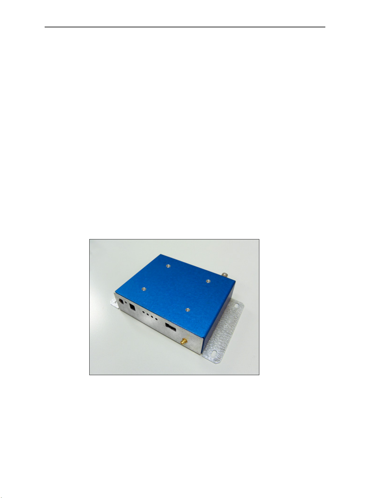
• An interface unit with reference board. The reference board provides a visual
layout of the Copernicus II GPS receiver on a printed circuit board (PCB), and
includes the RF signal trace, the RF connector, and the I/O connections of the 28
signal pins.
• Copernicus II GPS receivers (3)
• AC/DC power supply converter
• Universal power adapters for the major standard wall outlets
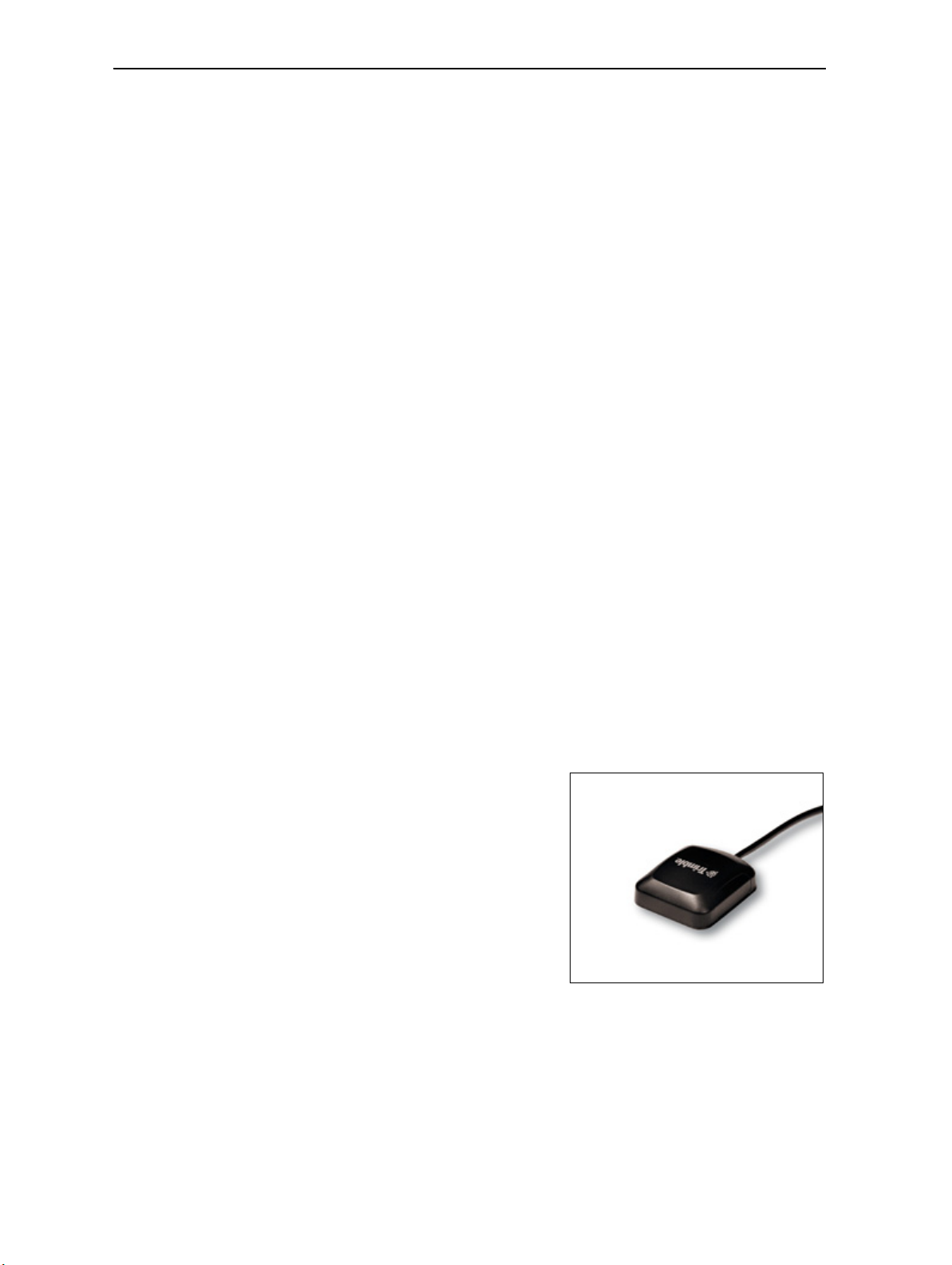
• Magnetic-mount GPS antenna, 3.3 V, MCX connector, 5 meter cable
• USB cable
• Cigarette lighter adapter power cable
• Quick Start Guide
• Software to evaluate the Copernicus II GPS when it is added to your
application—download the software from the Trimble Support website
Interface unit
Inside the starter kit interface unit, the Copernicus II GPS reference board is placed on
a shelf above the motherboard. It is supported by 4 standoffs. The antenna transition
cable is mounted to the outside of the unit and connects to the MCX connector on the
reference board. An 8-wire ribbon cable interfaces the power and I/O between the
reference board and the motherboard.
16 Copernicus II GPS Receiver Reference Manual
Page 19
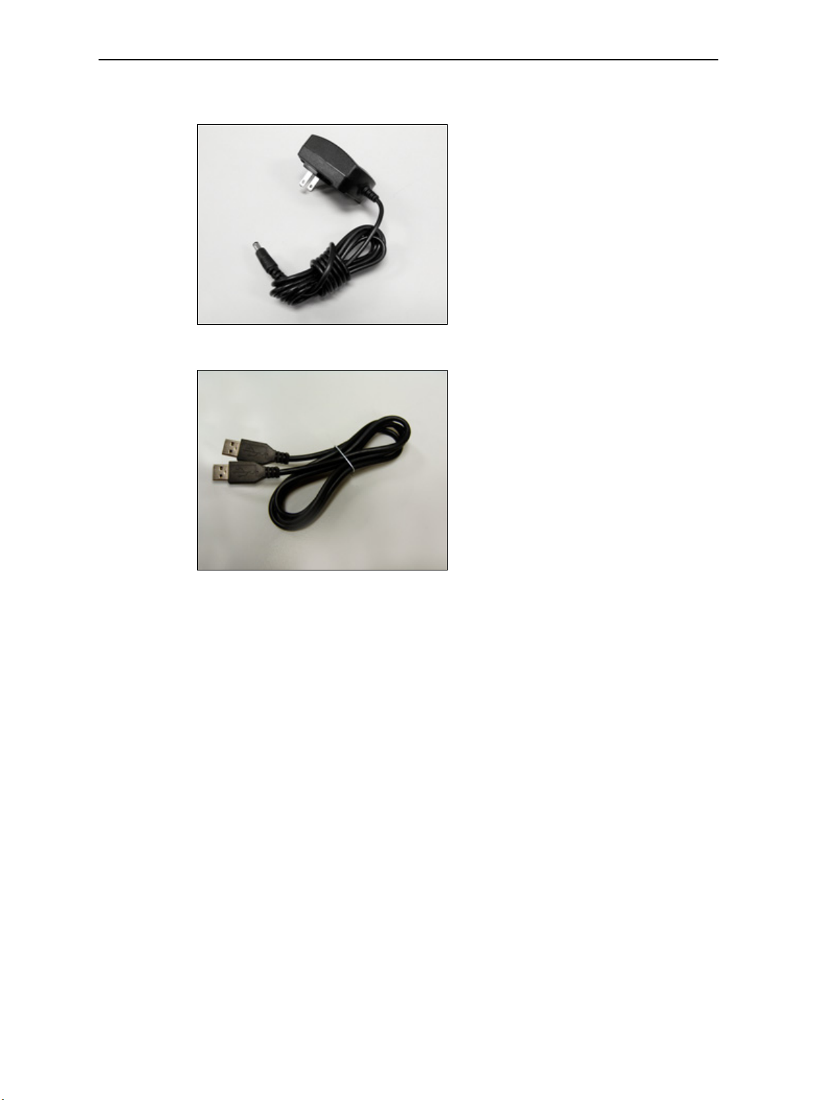
The following image shows the AC/DC power supply converter:
The following image shows the USB cable:
Starter Kit 2
Copernicus II GPS Receiver Reference Manual 17
Page 20
2 Starter Kit
c
d
efgh
ij
k
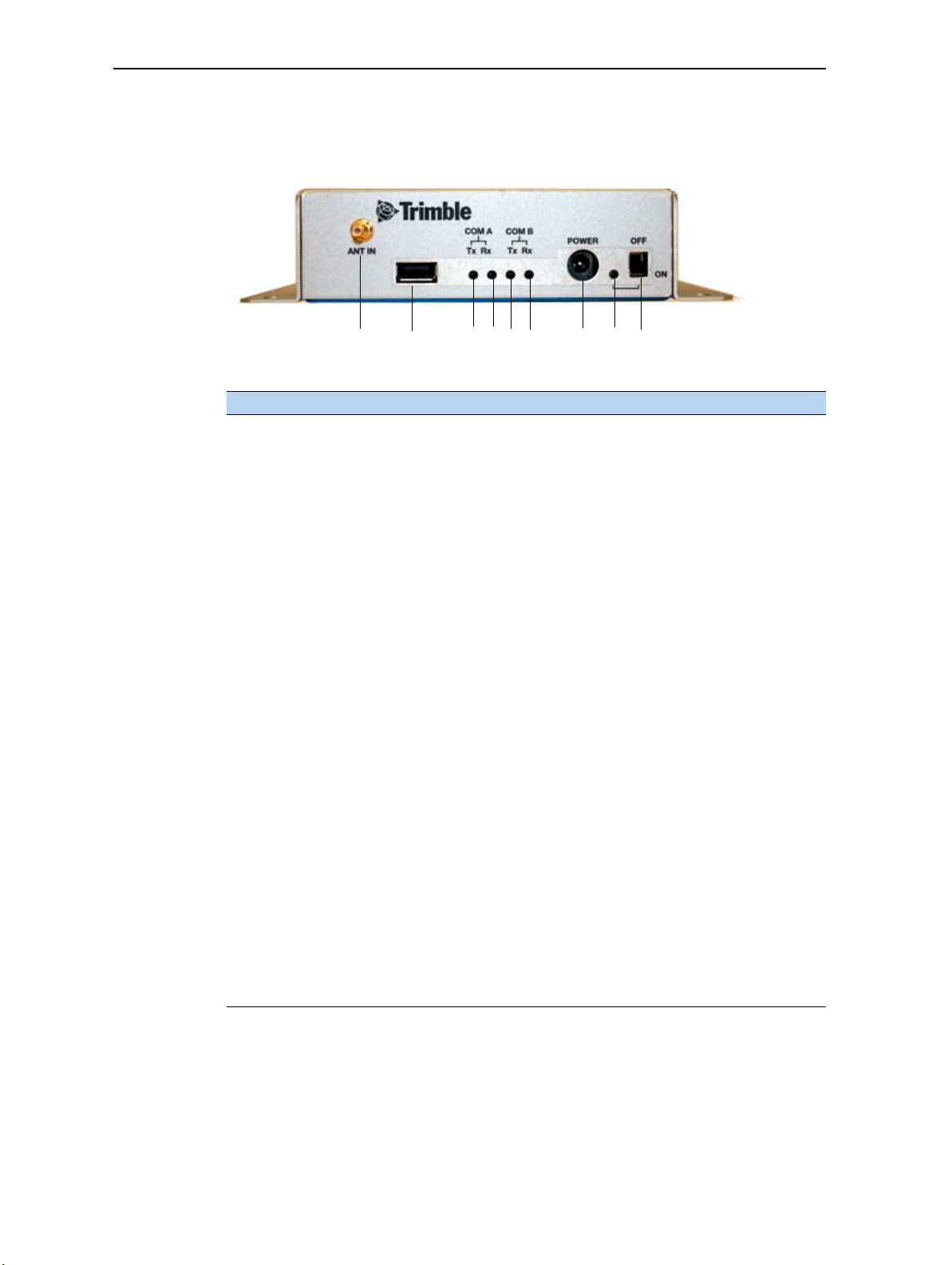
Interface connections
The front of the Copernicus II GPS interface unit has the following items:
Element Description
Antenna connector MCX-type connector for use with the supplied 3.0 V antenna. It
c
USB connector A-type USB connector that is USB 2.0 and 1.1 compatible. You
d
Port A-TX LED Blinks red if the user device is transmitting data to the
e
Port A-RX LED Blinks red if the Copernicus II GPS receiver is transmitting data to
f
Port B-TX LED Blinks red if the user device is transmitting data to the
g
Port B-RX LED Blinks red if the Copernicus II GPS receiver is transmitting data to
h
Power connector
i
(barrel connector)
Power LED Indicates that the receiver is powered by main power (VCC) from
j
Power switch Turns on or turns off the receiver.
k
connects to the Copernicus II GPS reference board antenna
connector.
can also use this connection to power the starter kit and GPS
receiver.
When you use the USB connection for power
run on AC power (not battery power), to ensure proper voltage
levels to the interface unit.
Copernicus II GPS receiver on port A.
the user device on port A.
Copernicus II GPS receiver on port B.
the user device on port B.
Connects to the AC/DC power converter supplied with the
starter kit. The power converter converts 100–240 VAC to 12 or
24 VDC. The power connector can accept 9 to 32 VDC.
the main power connector.
Main power is controlled by the power switch (see below). When
the switch
supplied to the receiver. When the switch is OFF, the LED is not lit
and the receiver is powered only by the standby regulator or
battery.
Note – For the Copernicus II
standby power, the power source must be from the main power
connector (#6), not from the USB connector.
is ON, the LED illuminates green and main power is
GPS receiver to operate with
the computer must
,
PPS BNC is located on the back of the interface unit. The BNC connector provides a
5 V TTL
by th
18 Copernicus II GPS Receiver Reference Manual
level PPS pulse output by the receiver. The output configuration is controlled
e receiver, not the starter kit driver circuit. This output can drive a 50 Ω load.
Page 21
Note – The Starter Kit motherboard contains a number of configuration jumpers for use
with various Trimble GPS receivers. Jumpers JP5 and JP15 must be in place for use with the
Copernicus II GPS receiver.
Removing the reference board from the interface unit
To remove the Copernicus II GPS reference board from the interface unit:
Starter Kit 2
Antenna
1. Before disassembling the interface unit, disc
onnect the unit from any external
power source and confirm that both you and your work surface are correctly
grounded for ESD protection.
2. Remove the four screws that secure the bottom plate of the interface unit to the
base o
f the metal enclosure. Set the bottom plate aside.
3. Remove the two screws that secure the Copernicus II GPS reference board to the
s
andoffs. These screws are located at opposite ends of the receiver module.
t
4. Disconnect the 8-way ribbon cable.
5. Remove the RF connector.
The Copernicus II receiver can work with both an active and a passive antenna:
• An "active" GPS antenna has a Low Noise Amplifier (LNA). The LNA makes up
for the signal loss that is inherent in all antenna cables. Active antennas require
power from the GPS receiver to power the LNA, which puts extra drain on the
receiver’s batteries.
• A “passive” GPS antenna does not include an LNA and therefore does not require
power. Because this type of GPS antenna is not powered, cable length usually
cannot exceed one meter.
The Copernicus II GPS starter kit comes with
an active mini magnetic mount 3.0 V GPS
e
nna. This antenna connects to the MCX
ant
connector on the interface unit. The reference
board supplies power to the active antenna
through the RF transition cable.
Using a passive antenna
To test performance with a passive antenna (not supplied in the Copernicus II GPS
Starter Kit) and ensure minimal signal loss, connect it directly to the MCX connector
on the reference board.
Copernicus II GPS Receiver Reference Manual 19
Page 22

2 Starter Kit
Since the passive antenna has no LNA, the antenna detection and short circuit will not
report a true antenna condition. If the passive antenna is a patch antenna (DC open),
the firmware reports an antenna open condition.
20 Copernicus II GPS Receiver Reference Manual
Page 23

CHAPTER
3
Copernicus II GPS Receiver: Features and Performance Specification
In this chapter:
Key features
Specifications
Absolute minimum and maximum
limits
Normal operating conditions
Power consumption over
temperature and voltage
ESD protection
This chapter describes the Copernicus II GPS
receiver features and performance specifications.
Note – Th
he Copernicus II and the Copernicus IIA unless
t
explicitly stated otherwise.
e content in this chapter applies to both
3
Copernicus II GPS Receiver Reference Manual 21
Page 24

3 Copernicus II GPS Receiver: Features and Performance Specification
Key features
• Thumbnail-sized shielded unit
• Ultra-thin design (2.54 mm)
• No I/O or RF connector—28 reflow-solderable edge castellations
• Ultra-low power usage, typically less than 132 mW
• Highly sensitive:
– −160 dBm tracking sensitivity
– –148 dBm acquisition sensitivity (hot start with ephemeris, otherwise
–144 dBm)
• Fast Time To First Fix (TTFF) from cold start
• Supports active or passive antenna designs
• 12-channel simultaneous operation
• Supports SBAS
• Supports NMEA 0183, TSIP, and TAIP protocols
• RoHS-compliant (lead-free)
• Manufactured and factory tested to Trimble highest quality standards
• Fast installation—tape and reel packaging, pick and place assembly
• Reference board and starter kit available for Copernicus II only. For Silvana and
Anapala options that contain the Copernicus IIA GPS module, see Appendix D,
Silvana and Anapala Antenna Companion Modules.
Feature differences between the Copernicus II and Copernicus IIA
Feature 63530-00 63530-10 67415-00
Standby serial command supported No Yes No
SHORT pin can be pulled HIGH when not used Yes Yes No (SHORT must be "no
co
ect" if not used)
nn
22 Copernicus II GPS Receiver Reference Manual
Page 25
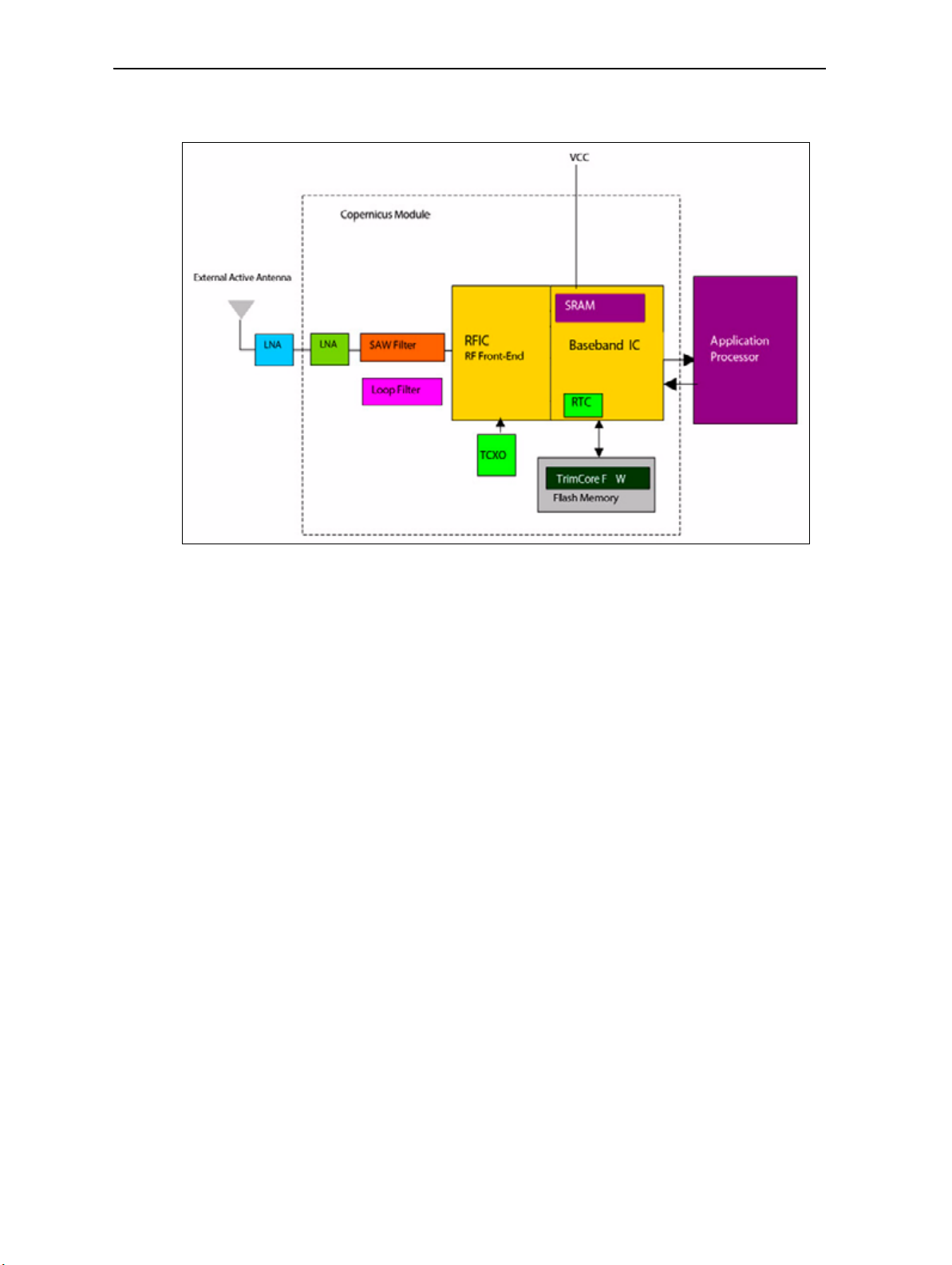
Block diagram
Copernicus II GPS Receiver: Features and Performance Specification 3
Copernicus II GPS Receiver Reference Manual 23
Page 26

3 Copernicus II GPS Receiver: Features and Performance Specification
Specifications
The following specifications apply to both the Copernicus II and the Copernicus IIA
module, unless explicitly stated otherwise.
Performance
The GPS module is an L1 (1575.42 MHz) frequency, C/A code, 12-channel, continuous
tracking receiver.
Update rate
TSIP 1 Hz
NMEA 1 Hz
TAIP 1 Hz
Accuracy (24 hour static)
Horizontal (without SBAS) <2.5 m 50%, <5 m 90%
Horizontal (with SBAS) <2.0 m 50%, <4 m 90%
Altitude (without SBAS) <5 m 50%, <8 m 90%
Altitude (with SBAS) <3 m 50%, <5 m 90%
Velocity 0.06 m/sec
PPS (static) ±60 ns RMS
PPS (stationary mode indoors at –145 dBm) ±350 ns RMS
Acquisition (autonomous operation)
Re-acquisition 2 sec
Hot start 3 sec
Hot start without battery back-up 8 sec (ephemeris not older than 4 hours)
Warm start 35 sec
Cold start 38 sec
Out of the box 41 sec
Sensitivity
Tracking –160 dBm
Acquisition sensitivity (standard sensitivity mode) –142 dBm
Acquisition sensitivity (high sensitivity mode) –148 dBm (hot start with ephemeris);
Operational
Speed limit 515 m/s
–144 dBm (otherwise)
24 Copernicus II GPS Receiver Reference Manual
Page 27

Interface
Connectors 28 surface-mounted edge castellations
Serial port 2 serial ports (transmit/receive)
PPS 3.0 V CMOS-compatible TTL-level pulse, once per second
Protocols Trimble Standard Interface Protocol (TSIP)
Electrical
Prime power 2.7 VDC to 3.3 VDC
Power consumption
(typical)
Backup power 2.7 VDC to 3.3 VDC
Ripple noise Max 50 mV, peak-to-peak from 1 Hz to 1 MHz
Copernicus II GPS Receiver: Features and Performance Specification 3
Trimble ASCII Interface Protocol (TAIP)
National Marine Electronics Association (NMEA) 0183 version 3.0
(bi-directional NM
44 mA (132 mW) at 3.0 V
EA messages)
Physical
Enclosure Metal shield
Dimensions (W x L x H) 19 mm x 19 mm x 2.54 mm (0.75" x 0.75" x 0.1")
Weight 1.7 grams (0.06 ounce), including shield
Environmental
Operating temperature –40 °C to +85 °C ( –40 °F to 185 °F)
Storage temperature –55 °C to +105 °C ( –67 °F to 221 °F)
Vibration 0.008 g
Operating humidity 5% to 95% R.H. n
2
/Hz, 5 Hz to 20 Hz
2
0.05 g
/Hz, 20 Hz to 100 Hz
-3 dB/octave, 100 Hz to 900 Hz
on-condensing, at 60 °C (140 °F)
Copernicus II GPS Receiver Reference Manual 25
Page 28

3 Copernicus II GPS Receiver: Features and Performance Specification
Absolute minimum and maximum limits
Absolute maximum ratings indicate conditions beyond which permanent damage to
the device may occur. Electrical specifications shall not apply when operating the
device outside its rated operating conditions.
Parameter Min Max Unit
Power supply
Power supply voltage (VCC) on Pin 12
Standby voltage (Vbat) on Pin 6
Antenna
Input power at RF input +10 dBm
Input gain at RF input 0 (passive antenna) 36 dB
-0.3 3.6 V
-0.3 3.6 V
Note – See S
tandby mode, page 42 for information on the standby current.
Input/Output pin threshold levels
Input pin voltage (RXD-A, RXD-B, Open, Short, Reserved Pins,XSTANDBY)
Status Min Max Unit
High 2.0 3.6 V
Low 0 0.8 V
Input pin voltage (XRESET)
Status Min Max Unit
High 2.0 3.6 V
Low 0 0.1 V
Output pin voltage (TXD-A, TXD-B, LNA_XEN)
Status Min Max Unit
High (loh = 1 mA) 0.8 * VCC VCC V
Low (lol = 1 mA) 0 0.2 * VCC V
26 Copernicus II GPS Receiver Reference Manual
Page 29

Copernicus II GPS Receiver: Features and Performance Specification 3
Normal operating conditions
Minimum and maximum limits apply over full operating temperature range unless
otherwise noted.
Parameter Conditions Min Typ Max Unit
Primary supply voltage The rise time to VCC must
140 μsecs. The user can use one source of
power
on Pin 12 (VCC) for both main and
standby power.
Current draw, continuous
tracking,
Power consumption,
nuous tracking,
conti
Power consumption
Absolute maximum
Current draw
Standby mode (XSTANDBY)
Standby mode (software)
Supply ripple noise 1 Hz to 1MHz
Typical: 25 °C (77 °F), 3.0 V 44 mA
Typical: 25 °C (77 °F), 3.0 V 132 mW
Typical: 25 °C (77 °F), 3.0 V
be greater than
2.7 3.3 * V
60
180
7
12
50
mA
mW
uA
uA
mVpp
GPS TCXO frequency 16.368 MHz ± 5 kHz
Hardware reset Assert XRESET pin to clear standby memory 100 us
1
Power consumption over temperature and voltage
Run mode
• Tracking with almanac complete: < 132 mW average at 2.7 VDC, –40 °C to +85 °C
(–40 °F to 185 °F)
• Standby mode: < 30 μW at 3.0 VDC, typical at 25 °C (77 °F); < 200 μW under all
conditions.
At 2.7 V Average current (mA) Average power consumption (mW)
–40 °C (–40 °F) 40 108
Room temperature 43 116
85 °C (185 °F) 46 124
At 3.0 V Average current (mA) Average power consumption (mW)
–40 °C (–40 °F) 40 120
Room temperature 43 129
85 °C (185 °F) 46 138
mVpp
Copernicus II GPS Receiver Reference Manual 27
Page 30

3 Copernicus II GPS Receiver: Features and Performance Specification
At 3.3 V Average current (mA) Average power consumption (mW)
–40 °C (–40 °F) 41 135
Room temperature 44 145
85 °C (185 °F) 47 155
ESD protection
ESD testing was performed using JDEC test standard JESD-A114C.01. All inputs and
outputs are protected to ±500 V ESD level. The RF input pin is protected up to 1 kV.
If a higher level of compliance is required, additional electrostatic and surge protection
st be added.
mu
28 Copernicus II GPS Receiver Reference Manual
Page 31

CHAPTER
4
Receiver Interface 4
In this chapter:
Pin assignments
Pin description
Serial port default settings
GPS timing
Assisted GPS (A-GPS)
Pulse-Per-Second (PPS)
This chapter provides a detailed description of
the Copernicus II GPS receiver interface.
Copernicus II GPS Receiver Reference Manual 29
Page 32

4 Receiver Interface
Pin assignments
30 Copernicus II GPS Receiver Reference Manual
Page 33

Receiver Interface 4
Pin description
Pin Name Description Function Note
1 GND Ground Ground Signal ground.
Connect to common ground.
2 GND RF Ground Ground One of two RF grounds adjacent to RF input.
Connect to RF ground system.
3 RF Input GPS RF input Input 50 Ω unbalanced (coaxial) RF input.
4 GND RF Ground Ground One of two RF grounds adjacent to RF input.
Connect to RF ground system.
5 LNA_XEN LNA Enable Output Can be used with active antennas only. Active low
lo
level signal to control external LNA.
gic
6 Vbat Battery backup Power Voltage supply for backup battery 2.7
7 OPEN Antenna OPEN Input Logic level from external antenna detection circuit.
S
ee the antenna detect truth table on page 33.
8 SHORT Antenna SHORT Input/
Output
9 Reserved Reserved Input Do not connect.
10 Reserved Reserved Input Do not connect.
11 XRESET Reset Input Active low logic level reset.
12 VCC Supply voltage Power Module power supply, 2.7 VDC to 3.3 VDC.
13 GND Ground Ground Signal ground.
14 GND Ground Ground Signal ground.
15 GND Ground Ground Signal ground.
16 XSTANDBY Run/Standby Input Selects “RUN” or “STANDBY” mode. ‘
17 Reserved Reserved Input/
Output
18 Reserved Reserved Input/
Output
19 PPS Pulse per second Output Logic level timing signal at 1 Hz.
20 RXD_B Serial port B receive Input Logic level secondary serial port
21 RX
22 Reserved
23 TXD_A Serial port A transmit Output Logic level primary serial port tr
24 TXD_B Serial port B transmit Output Logic level secondary serial port transmit.
25 Reserved Reserved I
D_A Serial port A receive Input Logic level primary serial port receive.
Reserved Input/
Output
nput/
Output
Logic level from external antenna detection circuit.
S
ee the antenna detect truth table on page 33.
Do not connect if not used.
Connect to common ground.
Connect to common ground.
Connect to common ground.
Connect to VCC if not used (run only).
Do not connect.
Do not connect.
Do not connect if not used.
Pull HIGH
Do not connect.
Do not connect.
if not co
nnected.
V to 3.3 V.
receive.
ansmit.
Copernicus II GPS Receiver Reference Manual 31
Page 34

4 Receiver Interface
Pin Name Description Function Note
26 Reserved Reserved Input/
Output
27 GND Ground Ground Signal ground.
28 GND Ground Ground Signal ground.
Do not connect.
Connect to common ground.
Connect to common ground.
Detailed pin descriptions
RF input
The RF input pin is the 50 Ω unbalanced GPS RF input, and can be used with active or
pa
ssive antennas.
• Passive antennas: You can connect the RF input pin to the passive GPS
antenna by a low-loss 50 Ω unbalanced transmission system if loss is minimal
(< 2 dB). Trimble recommends that you use an external LNA with a passive
enna.
ant
• Active antennas: You can also connect the RF input pin to the output of an
external low-noise amplifier, which amplifies GPS signals from the antenna. The
LNA gain must be great enough to overcome transmission losses from the LNA
output to this pin. The specification for noise for the module is < 3 dB at room
temperature and <4 dB over the specified temperature range, –40 °C to +85 °C
(–40 °F to +185 °F). Locate the external LNA so that the loss from the GPS
t
enna connection to the LNA input is minimized, preferably <1 dB. The noise
an
figure of the LNA should be as low as possible, preferably <2 dB. This
specification is provided to enable a cascaded noise figure design calculation.
Active antennas must be powered with a single bias-tee circuit.
LNA_XEN
Use this logic level output to control power to an external LNA or other circuitry. The
lo
gic of this signal is such that when the module is running (that is, not in standby
mode), the signal is low. In standby mode, the signal is high. You can use this pin to
control the gate of a p-channel FET that is used as a switch.
Open/Short pins
When you use an active antenna, Trimble recommends that you implement an
nna detection circuit with short circuit protection. Two pins are provided for
ante
reporting the antenna status: OPEN and SHORT.
You can use the logic level inputs in the
detection circuit (with or without protection) to monitor the status of the external
f an active antenna by the module.
LNA o
32 Copernicus II GPS Receiver Reference Manual
antenna detect truth table on page 33 with a
Page 35

Receiver Interface 4
The truth table for the logic of these signals is provided in the table below. These input
pins conform to the Input / Output Pin threshold levels described on page 26.
A typical active antenna draws between 10 mA to 20 mA.The antenna protect/detect
ci
cuit trips as a short circuit at around 100 mA. It is therefore advisable to keep the
r
antenna current below 75 mA. An open circuit is determined if the antenna current
falls below approximately 2 mA.
The antenna detect truth table below shows the condition of the logic signals:
Antenna reports Short Open
Antenna open reported 1 1
Antenna normal teported 1 0
Antenna shorted reported 0 0
Undefined 0 1
When you use a passive antenna with the OPEN pin floating, the receiver reports an
condition. If a normal condition from the receiver is required when using a
open
passive antenna, leave the SHORT pin unconnected (there is an internal pull-up) and
set the logic level of the OPEN pin to low.
XRESET
This logic-level, active low input is used to issue hardware or power-on reset to the
le. It may be connected to external logic or to a processor to issue reset. To reset
modu
the module, take this pin low for at least 100 microseconds. Do not connect the pin if
not used. See Absolute minimum and maximum limits, page 26 for pin threshold
values.
Copernicus II GPS Receiver Reference Manual 33
Page 36

4 Receiver Interface
XRESET circuit recommendations
The XRESET pin has to be pulled below 100 mV for at least 100 us to assure correct
set operation. The Copernicus II module should be externally reset by a
re
power-on-supervisor or host CPU.
The XRESET pin should be driven actively by an external power-on-reset circuit. It will
e c
ompatible with a CMOS totem-pole or open-drain driver:
b
The circuit below shows an example of a FET circuit used to invert a positive RESET
sig
nal:
VCC
This is the primary voltage supply pin for the module.
34 Copernicus II GPS Receiver Reference Manual
Page 37

Receiver Interface 4
Vbat
This pin provides power during standby mode (backup mode).
XSTANDBY
This logic level input is used to control the run/standby state of the module. If this
si
gnal is high, the unit runs normally. If it is low, the unit goes to standby mode. See
Absolute minimum and maximum limits, page 26 for pin threshold values.
PPS
Pulse-per-second. This logic level output provides a 1 Hz timing signal to external
device
s. The positive going 4.2 μsec pulse width is controllable by TSIP packet 0x8E-4F.
The cable delay and polarity is controllable by TSIP packet 0x8E-4A. The PPS mode is
set by TSIP packet 0x35. This output meets the input/output pin threshold
specifications (see Absolute minimum and maximum limits, page 26.)
RXD_A and RXD_B
These logic level inputs are the primary (A) and secondary (B) serial port receive lines
(d
ata input to the module). This meets the input/output pin threshold specifications
(see Absolute minimum and maximum limits, page 26). The baud rate for the two
ports is under software control.
RXD_A should be pulled High if not used. RXD_B already has an internal pull up.
TXD_A and TXD_B
These logic level outputs are the primary (A) and secondary (B) serial port transmit
line
s (data moving away from the module). This output meets the input/output pin
threshold specifications (see Absolute minimum and maximum limits, page 26). The
baud rate for the two ports is under firmware control
.
Reserved pins
There are 7 reserved pins on the Copernicus II GPS receiver. For the recommended pin
conn
ections for these reserved pins, see the Pin description table, page 31.
Protocols
The following protocols are available for the Copernicus II GPS receiver:
Protocols Specification Direction Serial port
support
NMEA 0183,
version 3.0
TSIP Trimble proprietory binary protocol Input / Output Both serial ports
TAIP Trimble proprietory ASCII protocol Input / Output Both serial ports
Bidirectional with extended NMEA
sentences
Input / Output Both serial ports
Copernicus II GPS Receiver Reference Manual 35
Page 38

4 Receiver Interface
Port B serial communication
Note the following to avoid problems with missing or mistimed NMEA messages.
• How does Port B affect Port A? Every second, GPS data comes out on Port A
first, then on Port B. If Port B generates a lot of serial traffic and takes up a
significant amount of time, Port A will not send out data on time during the
following second.
For example, if the Trimble GPS Studio application is used with AUTO-QUERY
at a 4800 baud rate on Port B, this will overload the unit. To run the Trimble
ON
GPS Studio application on Port B with minimum impact, change the baud rate
appropriately. A count of the bytes sent will determine which baud rates will
work correctly.
• If Port B is not used, turn it off completely with this TSIP 0xBC Protocol
Configuration command:
10 BC 01 06 06 03 00 00 00 00 00 00 10 03
Serial port default settings
The Copernicus II GPS receiver supports two serial ports. The default settings are:
Port Port
direction
A TXD-A 23 TSIP-Out 38.4 K 8 None 1 NO
RXD-A 21 TSIP-IN 38.4 K 8 None 1 NO
B TXD-B 24 NMEA-Out 4800 8 None 1 NO
RXD-B 20 NMEA-IN 4800 8 None 1 NO
Pin # Protocol Characteristics
Baud rate Data bits Parity Stop bits Flow control
Note – You can configure the protocol and Baud rates on
ly. For a detailed description of
these protocols, see the Appendices.
GPS timing
In many timing applications, such as time/frequency standards, site synchronization
systems, and event measurement systems, GPS receivers are used to discipline local
oscillators.
The GPS constellation consists of 24 orbiting satellites. Each GPS satellite contains a
hig
hly-stable atomic (Cesium) clock that is continuously monitored and corrected by
the GPS control segment. Consequently, the GPS constellation can be considered a set
of 24 orbiting clocks with worldwide 24-hour coverage.
36 Copernicus II GPS Receiver Reference Manual
Page 39

Receiver Interface 4
GPS receivers use the signals from these GPS clocks to correct their internal clock
which is not as stable or accurate as the GPS atomic clocks. GPS receivers like the
Copernicus II output a highly accurate timing pulse (PPS) generated by an internal
clock which is constantly corrected using the GPS clocks. This timing pulse is
synchronized to UTC within ±60 ns rms.
In addition to serving as a highly accurate stand-alone time source, GPS receivers are
used to
synchronize distant clocks in communication or data networks. This
synchronization is possible since all GPS satellite clocks are corrected to a common
master clock. Therefore, the relative clock error is the same, regardless of which
satellite or satellites are used. For timing applications requiring a common clock, GPS
is the ideal solution.
Position and time errors are related by the speed
of light. Therefore, a position error of
100 meters corresponds to a time error of approximately 333 ns. The hardware and
software implementation affects the GPS receiver's PPS accuracy level. The receiver's
clocking rate determines the PPS steering resolution.
Serial time output
You must take time from the timing messages in the protocol you are using as position
messages contain a timestamp that is usually 1 to 2 seconds in the past.
Protocol Timing Message
TSIP Report packets 41 and 8F-21
TAIP TM message
NMEA ZDA message
Note – GPS time differs from UTC (Universal Coordinated Time) by a variable, integer
n
umber of seconds UTC=(GPS time) – (GPS UTC offset). As of January 2009, the UTC offset
is 15 seconds. Read the offset value as a part of the timing interface to obtain UTC. The
GPS week number is in reference to a base week (Week #0), starting January 6, 1980.
Acquiring the correct time
Do the following:
1. Confirm that the almanac is complete and that the receiver is generating 3D
fi
xes. This eliminates the UTC offset jump.
2. Confirm that the receiver is configured for the late PPS option (that is, it only
outp
uts a PPS on a 3D fix).
3. If you are using TSIP, capture the time from TSIP packet 0x41 or TSIP packet
0x
0.
8F-2
4. Once time is acquired, add 1 to the whole second on the next PPS to read the
rrect time.
co
Note – The minimum time resolution is 1 second.
Copernicus II GPS Receiver Reference Manual 37
Page 40

4 Receiver Interface
Assisted GPS (A-GPS)
The Copernicus II GPS receiver is equipped with assisted GPS (A-GPS), which enables
it to obtain a position fix within seconds using almanac, ephemeris, time, and position
data. This position data can be uploaded to the device using TSIP packets or the
Trimble GPS Studio application. When A-GPS is enabled, the Copernicus II GPS
receiver can achieve fast start-up times that are characteristic of a hot start.
To download current almanac, ephemeris, time, and position information, and then
uplo
ad this data to the starter kit module through TSIP or the Trimble GPS Studio
application do the following:
C
CAUTION – To ensure correct formatting of the ephemeris file and almanac file, you must
use a Trimble receiver to gather this data. Almanac files from non-Trimble receivers or
elsewhere (for example, downloaded from the Internet) may not be in the correct format
and may not work.
Enabling A-GPS with the Trimble GPS Studio software
1. Attach the Copernicus II interface unit to your computer.
2. Place the GPS antenna where there is a clear view of sky.
3. Allow the starter kit to run and calculate fixes.
4. On the main screen, wait for the almanac indicator to turn green. This confirms
th
at the receiver has collected a current almanac.
Note – It takes 12½ minutes of uninterrupted Coper
from the satellites.
5. Click the initialized drop-down menu and
bottom of the menu to download the almanac, position, time, and ephemeris
files to your computer.
6. Use the upload features on the initiali
interface to upload the features.
nicus II operation to collect almanac
the download features at the
use
ze pull-down window in the Trimble
Note – The collected ephemeris is only good for approximately 2 hours.
Enabling A-GPS with TSIP
1. Allow the receiver to run long enough to collect a current almanac.
Note – It takes 12.5 minutes of uninterrupted Coper
from the satellites.
2. Use packet 0 x 26 to request the health of the receiver. The response packets
and 0x4B indicate when the almanac is complete and current.
0x46
3. Use packet 0x38 to request the almanac and the ephemeris. The receiver
re
sponds with packet 0 x 58.
38 Copernicus II GPS Receiver Reference Manual
nicus II operation to collect almanac
Page 41

Receiver Interface 4
4. Use packet 0 x 21 to request time from the receiver. The receiver responds with
packet 0x 41. This data can be used to set your own off-board clock.
5. Use packets 0x42, 0x4A, 0x83 0r 0x84 to request a position from the receiver.
To upload this information back to the receiver, follow this procedure in the specified
or
er:
d
1. Upload the time using TSIP packet 0x2E. Wait for upload confirmation report
pac
et 0x41.
k
2. Upload position using TSIP packet 0x31 or 0x32. No confirmation report packet
ailable.
av
3. Upload the ephemeris using TSIP packet 0x38. Wa
report TSIP packet 0x58.
Note – S
ee Appendix A for details on the TSIP protocol.
Pulse-Per-Second (PPS)
The Copernicus II GPS receiver provides a CMOS compatible TTL level
Pulse-Per-Second (PPS). The PPS is a positive pulse and is available on pin 19 of the
Copernicus II GPS receiver. The rising edge of the PPS pulse is synchronized with
respect to UTC. The timing accuracy is ±60 ns when valid position fixes are reported.
The precise UTC or GPS time is reported in TSIP message 0x41 and NMEA message
EDA
. The line reports are sent within 500 ms after the corresponding PPS is sent.
The rising edge of the pulse is typically less than 6 nanoseconds. The distributed
imp
ance of the attached signal line and input circuit can affect the pulse shape and
ed
rise time. The PPS can drive a load up to 1mA without damaging the module. The
falling edge of the pulse should not be used.
The Copernicus II default PPS output mode is Always On, sometimes called “Early
PP
S”. In Always On mode, PPS is output immediately after main power is applied. The
PPS is driven by the Real Time Clock (RTC) until the receiver acquires GPS time from
the satellite and begins outputting fixes. In Always On mode, the PPS continues even if
the receiver loses GPS lock. The drift of the PPS, when the Copernicus II GPS receiver is
not tracking satellites, is unspecified and should not be used for synchronization.
it for the upload confirmation
The PPS output modes can be controlled with TSIP packet 0x35 and the NMEA PS
packet. Th
compensation is available through the use of TSIP packet 0x8E-4A and the NMEA PS
packet. PPS pulse width is controlled by TSIP packet 0x8E-4F and the NMEA PS
packet.
After a specific mode is selected, it can be st
TSIP command 0x8E-26.
e modes are Always On (default), Fix Based, or Always Off. Cable delay
ored in non-volatile (Flash) memory, using
Copernicus II GPS Receiver Reference Manual 39
Page 42

4 Receiver Interface
Stationary mode
Note – PPS can be configured as positive or negative polarity; the factory default is
positive. The PPS pulse width can also be configured; the factory default is 4.2
microseconds.
In addition to the LAND, SEA, and AIR dynamics mode, the Copernicus II can operate
in Stationary mode to produce an accurate and stable PPS using an indoor antenna. In
this mode, the receiver conducts a self-survey of about 10 minutes with a clear view, or
for a longer period with an obstructed view. When the self-survey is complete, the
device outputs PPS while tracking one or more satellites.
Features include:
• TRAIM on clock and frequency
• Noise filter to reduce PPS variance
Note – Use TSIP Command 0xBB or NMEA Command CR to set Stationary mode. When
he receiver is in Stationary mode, the dimension type in TSIP packet 0x6D and in the
t
NMEA GSA messages is 2D.
40 Copernicus II GPS Receiver Reference Manual
Page 43

CHAPTER
5
Operating Modes 5
In this chapter:
Copernicus II GPS receiver
operating modes
Switching between operating
modes
SBAS
GPS receiver acquisition
sensitivity
This chapter describes the primary Copernicus II
GPS receiver operating modes and provides
guidelines for receiver operation.
Copernicus II GPS Receiver Reference Manual 41
Page 44

5 Operating Modes
Copernicus II GPS receiver operating modes
Run mode
This is the continuous tracking or normal mode.
Standby mode
This is backup power or low power mode.
In Standby mode the Copernicus II GPS receiver's RAM memory is kept alive and the
rea
l-time clock runs while the rest of the receiver is turned off. RAM memory is used to
store the GPS almanac, ephemeris, and last position.
Using this information, together with the time information provided by the real-time
cloc
k, the receiver normally provides faster startup times. The type of start-up after
Standby mode depends on the state of the receiver before entering Standby mode and
on the length of time the receiver spent in Standby mode.
If the receiver has almanac, ephemeris, an
Standby mode, and the time spent in Standby mode is less than two hours, the receiver
typically performs a hot start.
If the receiver has all of the information list
mode is more than two hours, the receiver typically performs a warm start.
The GPS almanac, ephemeris and recent position are automatically stored in
non-
olatile Flash memory. Even without time, the receiver can use the information
v
stored in Flash memory to shorten the start-up time. In all cases, the receiver uses all of
the available information to start up as quickly as possible.
Note – In Standby mode, the power consumption of the unit is very low. See St
page 42.
Monitor mode
Monitor mode is Flash upgrading mode.
Monitor mode is the operating mode for upgrading the firmware stored in the Flash
mem
ory. See also Chapter 12, Firmware Upload.
Switching between operating modes
d position information before entering
ed above, but the time spent in Standby
andby mode,
To switch the receiver between Run mode and Standby mode, you can do one of the
following:
• Use the XSTANDBY pin, see page 43.
• Use the serial ports under user control, see page 43.
42 Copernicus II GPS Receiver Reference Manual User Guide
Page 45

Operating Modes 5
Note – If you use the XSTANDBY pin, do not use the serial ports to control the modes. If you
use the serial port option, the XSTANDBY pin must be held high. You cannot use serial
ports to switch to RUN mode if the XSTANDBY pin was used to enter STANDBY mode.
Using the XSTANDBY pin to switch modes
Use the XSTANDBY pin (pin #16) to put the receiver into Standby mode or switch back
to Run mode.
As long as the pin is held high, the receiver operates normally in Run mode. When the
taken low, the receiver goes to Standby mode.
pin is
When the pin is taken high again, the receiver performs a hot or warm restart and
re
turns to normal operation. The receiver will hot start if the ephemeris is still valid.
Note – E
xcessive noise on the XSTANDBY pin can trigger the receiver to reset.
Using serial ports to switch modes
Alternatively, using TSIP packet 0xC0 or NMEA packet RT to put the receiver into
Standby mode.
There are two conditions that could trigger the receiver to exit Standby mode and reset
to no
rmal operations:
• Serial port activity
• Exit after elapsed time
These conditions are described below.
Serial port activity
When the receiver enters Standby mode through the software protocol commands, the
fi
rst condition for exiting Standby mode is using serial port A activity or serial port B
activity. The condition is identical for both ports A and B.
To ensure that the receiver detects and responds to serial port activity, issue a null
chara
cter on the selected serial port to bring the unit out of Standby mode. In Standby
mode, the receiver samples for serial port activity at a rate of 32.768 kHz. A null
character will bring the selected RX line low for 9 bits so even at the highest baud rate
of 115200, a null character should be detectable at the sample rate.
When shutting down, it may take up to 3 seconds to enter Standby mode. Once in
Stand
by mode wait for at least 3 seconds before returning the unit to Run mode.
Exit after elapsed time
Use the TSIP command Packet 0xC0 or NMEA packet R
T to force the receiver to exit
Standby mode after a defined elapsed time. Specify the number of seconds the receiver
should remain in Standby mode. Once this time has elapsed, the receiver resets and
starts operating normally.
Copernicus II GPS Receiver Reference Manual User Guide 43
Page 46

5 Operating Modes
Saving almanac, ephemeris, and position data to Flash memory
Graceful Shutdown
SBAS
The almanac, ephemeris, and recent position data contained in RAM is automatically
saved to Flash memory.
The Graceful Shutdown command is issued using TSIP packet 0xC0 or NMEA
command RT with the “Store RAM to Flash” flag enabled. The reset type depends on
the Graceful Shutdown command parameters. On start-up, the unit uses the almanac,
ephemeris, and position from RAM first. If the RAM is not available, the unit uses the
almanac from the Flash memory.
The Satellite Based Augmentation System (SBAS) includes implementation of the
current standard for the Wide Area Augmentation System (WAAS) and the European
Geostationary Navigation Overlay Service (EGNOS) operated by the European Space
Agency, as well as other compatible systems that will be available in the future.
WAAS
The Wide Area Augmentation System (WAAS) is an extremely accurate navigation
system developed for civil aviation by the Federal Aviation Administration (FAA). The
system augments GPS to provide the additional accuracy, integrity, and availability
information to enable users to rely on GPS for all phases of flight for all qualified
airports within the WAAS coverage area.
The worst-case accuracy is within 7.6 meters of the true position 95% of the time. This
achieved using a network of ground stations located throughout North America,
is
which monitor and measure the GPS signal. Measurements from the reference stations
are routed to two master stations, which generate and send the correction messages to
geostationary satellites. Those satellites broadcast the correction messages back to
Earth, where WAAS-enabled GPS receivers apply the corrections to their computed
GPS position.
Number of channels
The Copernicus II GPS receiver tracks one WA
and tracking a WAAS satellite, one tracking channel is set aside for this purpose,
leaving eleven tracking channels which are used for GPS satellites.
AS satellite at a time. When acquiring
44 Copernicus II GPS Receiver Reference Manual User Guide
Page 47

Operating Modes 5
Acquisition
The receiver acquires a WAAS satellite after it has a GPS-based position fix. After a
o-minute position fix outage, the receiver stops tracking and acquires the WAAS
tw
satellite. The WAAS satellite is re-acquired once the GPS-based position fix is reestablished.
Usage
The receiver only uses the data from a WAAS satellite for position fix corrections. It
does
not use a WAAS satellite for computing position solutions.
Almanac collection
The receiver collects WAAS almanac data and automatically stores the WAAS satellite
lo
, and abbreviated almanac and health data.
cation
The receiver does no
set of WAAS corrections.
ollect or store WAAS ephemeris data. The module stores one
t c
GPS receiver acquisition sensitivity
By default, the Copernicus II GPS receiver’s Acquisition Sensitivity is set to Standard. If
your application requires frequent operation indoors or in obscured GPS signal
conditions, switch to High Sensitivity Mode. When High Sensitivity mode is enabled, if
the initial search fails to find a strong GPS signal, then the receiver enters deep search
mode and the time-to-first fix may take longer than normal. If during this period the
receiver is moved into bright signal conditions, the time-to-first-fix may also take
longer than normal. To avoid this issue, operate the receiver in the Standard
Acquisition Sensitivity mode.
Note – The Acquisition Sensitivity Mode setting does not affect tracking sensitivity
pe
rformance.
Copernicus II GPS Receiver Reference Manual User Guide 45
Page 48

5 Operating Modes
46 Copernicus II GPS Receiver Reference Manual User Guide
Page 49

CHAPTER
6
Application Circuits 6
In this chapter:
Passive antenna—Minimum
connections
Passive antenna—Hardware
activated standby
Active antenna—Full connection
Active antenna—Short circuit
connection
Active antenna—No antenna
status
This chapter describes the Copernicus II GPS
receiver passive and active antenna connections.
For a description of passive and active antenna
co
nections, see page 19.
n
Copernicus II GPS Receiver Reference Manual User Guide 47
Page 50

6 Application Circuits
Passive antenna—Minimum connections
The minimum connection set for the Copernicus II GPS receiver is shown above:
• A passive antenna is used. The receiver has an on-board LNA and an automatic
gain control circuit.
• The pin LNA_XEN is not necessary and is not connected.
• There is no hardware reset ability through the pin XRESET, since the XRESET
pin is not connected.
• There is no hardware-initiated Standby mode through the pin XSTANDBY, since
XSTANDBY pin is tied High to VCC. The software serial command to Standby
mode will still apply.
• There is no separate power for STANDBY power.
• One serial port is used.
• No Antenna open and short detection or protection is provided. When Open
(Pin 7) and Short (Pin 8) are kept unconnected ( floating), the receiver reports an
open antenna condition. If a normal condition is desired, tie Open Low. See the
antenna detect truth table on page 33.
48 Copernicus II GPS Receiver Reference Manual User Guide
Page 51

Passive antenna—Hardware activated standby
Application Circuits 6
In the figure above:
• A passive antenna is used. The receiver has an on-board LNA and an automatic
gain control circuit.
• The pin LNA_XEN is not necessary and not connected.
• There is no hardware reset ability through the pin XRESET.
• Hardware-initiated Standby mode through the pin XSTANDBY is possible, since
XSTANDBY pin is not tied High to VCC. The software serial command to
Standby mode can still be used as a second method to force the module into
Standby mode. See Switching between operating modes, page 42.
• There is no separate power for STANDBY power.
• One serial port is used.
• No Antenna open and short detection or protection is provided. When Open
(Pin 7) and Short (Pin 8) are kept unconnected ( floating), the receiver reports an
open antenna condition. If a normal condition is desired, tie Open Low. See the
antenna detect truth table on page 33.
Copernicus II GPS Receiver Reference Manual User Guide 49
Page 52

6 Application Circuits
Active antenna—Full connection
In the figure above, the Copernicus II GPS receiver has short circuit antenna detection,
and uses a second source to power the unit when it is in Standby mode:
• An active antenna is used.
• The pin LNA_XEN is connected.
• Hardware reset ability is possible through pin XRESET.
• Hardware-initiated Standby mode is possible through pin XSTANDBY, since
XSTANDBY pin is not tied High to VCC. See Standby mode, page 42.
• A second power source is applied for the standby voltage.
• Both serial ports are used.
• Antenna open and short detection and protection is provided. The combination
of the two pins Open (pin 7) and Short (pin 8) report the antenna status (see
Open/Short pins, page 32).
50 Copernicus II GPS Receiver Reference Manual User Guide
Page 53

Application Circuits 6
• The component information is shown below:
Component Description Manufacturer Part Number
C1 0.1 uF, 0402 capacitor, X7R CAL-CHIP GMC04X7R104K16NTLF
C2 18 PF, 0402 capacitor, C0G KEMET C0402C180J5GAC
Q1A P-Channel MOSFET Fairchild FDG6316P
J1 MCX Connector Johnson Components 133-3711-312
L1 100 nH, 0603 inductor,
surface mount
Q2 PNP Transistor Central Semiconductor CMPT404A (MMBTA70LT1 may be used
Q3 NPN Transistor Philips MMBT3904
Q4 PNP Transistor Philips MMBT3906
Q5 PNP Transistor Philips MMBT3906
DI Switching Diode ON Semiconductor MMBD914LTIG
Coil Craft 0603CS - R10XJLU
if 12 V
required)
lt back voltage tolerance is not
o
Copernicus II GPS Receiver Reference Manual User Guide 51
Page 54

6 Application Circuits
Active antenna—Short circuit connection
In the figure above, the Copernicus II GPS receiver has short circuit antenna detection,
and uses a second source to power the unit when it is in Standby mode:
• An active antenna is used.
• The pin LNA_XEN is connected.
• Hardware reset ability is possible through pin XRESET.
• Hardware-initiated Standby mode is possible through pin XSTANDBY, since the
pin is not tied High to VCC. See Standby mode, page 42.
• A second power source is applied for the standby voltage.
• Both serial ports are used.
• Antenna short detection and protection is provided. The combination of the
two pins Open (pin 7) and Short (pin 8) report the antenna status (see
Open/Short pins, page 32).
52 Copernicus II GPS Receiver Reference Manual User Guide
Page 55

Application Circuits 6
• Component information is shown below:
Component Description Manufacturer Part Number
C1 0.1 uF, 0402 capacitor, X7R CAL-CHIP GMC04X7R104K16NTLF
C2 18 PF, 0402 capacitor, C0G KEMET C0402C180J5GAC
Q1A P-Channel MOSFET Fairchild FDG6316P
J1 MCX Connector Johnson Components 133-3711-312
L1 100 nH, 0603 inductor, surface
mo
unt
Q2 PNP Transistor Central Semiconductor CMPT404A (MMBTA70LT1 may be
Q3 NPN Transistor Philips MMBT3904
DI Switching Diode ON Semiconductor MMBD914LTIG
Co
il Craft 0603CS - R10XJLU
used
if 12 Volt back voltage
tolerance is not required)
Copernicus II GPS Receiver Reference Manual User Guide 53
Page 56

6 Application Circuits
Active antenna—No antenna status
In the figure above, the Copernicus II GPS receiver has no antenna detection and no
separate power source for Standby mode:
• An active antenna is used.
• The pin LNA_XEN is not connected.
• There is no hardware reset ability through the pin XRESET.
• Hardware-initiated Standby mode is possible through the pin XSTANDBY, since
XSTANDBY pin is not tied High to VCC. See Standby mode, page 42.
• There is no separate power for STANDBY power.
• Both serial ports are used.
• Antenna open and short detection or protection is not provided. If pins 7 and 8
are left floating, they will cause the unit to report an antenna open condition. If a
normal condition is desired, tie Open Low (see Open/Short pins, page 32).
54 Copernicus II GPS Receiver Reference Manual User Guide
Page 57

CHAPTER
7
RF Layout Considerations 7
In this chapter:
General recommendations
Design considerations for RF track
topologies
PCB considerations
This chapter outlines RF and PCB design
considerations for the Copernicus II GPS
receiver.
Copernicus II GPS Receiver Reference Manual 55
Page 58

7 RF Layout Considerations
General recommendations
The design of the RF transmission line that connects the GPS antenna to the
Copernicus II GPS receiver is critical to system performance. If the overall RF system is
not implemented correctly, the receiver performance may be degraded.
The radio frequency (RF) input on the Copernicus II GPS module is a 50 Ω, unbalanced
input. T
castellation on pin 3. This RF input may be connected to the output of an LNA which
has a GPS antenna at its input or to a passive antenna via a low-loss 50 Ω, unbalanced
tr
If the GPS antenna must be located any significant distance from the receiver, the use
o
from the antenna to the Copernicus II GPS module. Trimble recommends that, in the
case of a passive antenna, the transmission line losses from the antenna to the module
are less than 2 dB. Otherwise an LNA should be added to the system.
The specifications for the external LNA required can be determined as follows:
here are ground castellations, pins 2 and 4, on both sides of the RF input
ansmission line system.
an LNA at the antenna location is necessary to overcome the transmission losses
f
• The specification of noise figure for the Copernicus II GPS module is 3 dB at
room temperature and 4 dB over the temperature range −40 °C to ± 85 °C (−40 °F
to ± 185 °F).
• The noise figure for the external LNA should be as low as possible, with a
recommended maximum of 1.5 dB. Trimble recommends that the gain of the
LNA exceeds the loss as measured from the LNA output to the module input by
10 dB. For example, if the loss from the external LNA output is 10 dB, the
recommended minimum gain for the LNA is 20 dB. To keep losses at the LNA
input to a minimum, Trimble recommends that you connect the antenna
directly to the LNA input, to ensure the minimum loss possible.
• Connections to either the LNA output or to a passive antenna must be made
using a 50 Ω unbalanced transmission system. This transmission system may
any form, such as microstrip, coaxial, stripline or any 50 Ω characteristic
take
imp
edance unbalanced, low-loss system.
• You must keep noise sources with frequencies at or near 1575 MHz away from
the RF input. In the case of a passive antenna, the antenna must not be placed in
a noisy location (such as too close to digital circuitry) as this may degrade
performance. You may use shielded transmission line systems (stripline, coaxial)
to route the signal if noise ingress is a concern.
• If you use an active antenna and you want to power this antenna from the RF
transmission line, a bias-tee will be required at the Copernicus II GPS module
end. A simple series inductor (that is parallel resonant at 1575 MHz) and shunt
capacitor (series resonant at 1575 MHz) to which the bias voltage is supplied is
sufficient. You can also use an open/short detection and over-current
protection circuit. See Chapter 6, Application Circuits.
56 Copernicus II GPS Receiver Reference Manual
Page 59

• In the printed circuit board (PCB) layout, Trimble recommends that you keep
the copper layer on which the receiver is mounted clear of solder mask and
copper (vias or traces) under the module. This is to ensure mating of the
castellations between the Copernicus II GPS module and the board to which it is
mounted, so that there is no interference with features beneath the receiver that
cause it to lift during the re-flow solder process.
• For a microstrip RF transmission line topology, Trimble recommends that the
layer immediately below the one to which the receiver is mounted is the ground
plane. Use low-inductance connections to connect pins 2 and 4 directly to the
ground plane. You can use the correct geometry for a 50 Ω to route pin 3 (the RF
put) on the top layer.
in
Design considerations for RF track topologies
For the RF layout of the Copernicus II GPS receiver, consider the following:
• PCB track connection to the RF antenna input must have an impedance of 50 Ω
and be as short as possible.
• If you are using an external antenna, the PCB track connection to the RF
antenna input must transition from the circuit board to the external antenna
cable. This is typically an RF connector.
RF Layout Considerations 7
• If there are any ground planes on the same layer as the microstrip trace, see the
Coplaner Waveguide design. This is not included in this user guide.
• Route PCB track connection to the RF antenna input away from potential noise
sources such as oscillators, transmitters, digital circuits, switching power
supplies, and so on.
• RF and bypass grounding must be direct to the ground plane through its own
low-inductance via.
• You may use active or passive antennas. When using a passive antenna, the
connection to the antenna input must be very short. You can mount the patch
antenna on the same PCB as the Copernicus II GPS module. Designers must be
aware of noise generating circuitry and must ensure correct design precautions
( for example, shielding) are taken.
v
The PCB track connection to the RF antenna input must not ha
• Sharp bends.
• Components overlaying the track.
• Routing between components to avoid undesirable coupling.
e:
Copernicus II GPS Receiver Reference Manual 57
Page 60

7 RF Layout Considerations
PCB considerations
The minimum implementation is a two-layer PCB substrate with all the RF signals on
one side and a solid ground plane on the other. You can also use multilayer boards.
Two possible RF transmission line topologies are microstrip and stripline.
Microstrip transmission lines
Ground plane design
Trimble recommends that you use a complete ground plane immediately under the
B layer on which the Copernicus II GPS module is mounted. Around the signal
PC
tracks on the same layer as the module, flood or “copper pour” and then use lowinductance vias to connect the module to the ground plane. A single ground plane is
adequate for both analog and digital signals.
Microstrip transmission line design
You must use a 50 Ω unbalanced transmission system to connect to the LNA output or
to a pass
• Track width (W)
• PCB substrate thickness (H)
• PCB substrate permittivity (ε
• To a lesser extent, PCB copper thickness
ive antenna. The following PCB parameters affect impedance:
)
r
(T) and proximity of same layer ground
plane.
58 Copernicus II GPS Receiver Reference Manual
Page 61

RF Layout Considerations 7
The following table shows typical track widths for an FR4 material PCB substrate
(permittivity ε
of 4.6 at 1.5 GHz) and different PCB thicknesses. One ounce copper is
r
assumed for the thickness of the top layer. If a multilayer PCB is used, the thickness is
the distance from signal track to nearest ground plane:
Substrate
material
FR4 4.6 1.6 2.91
Permittivity Substrate thickness
H (mm)
1.2 2.12
1.0 1.81
0.8 1.44
0.6 1.07
0.4 0.71
0.2 0.34
Track width
W (mm)
Microstrip design
Trimble recommends that you route the antenna connection PCB track around the
ide of the module outline, keep it on a single layer and make sure that there are no
outs
bends greater than 45 degrees. For production reasons, do not route the track under
the module.
Stripline transmission lines.
Ground plane design
The stripline topology requires three PCB layers: two for ground planes and one for
gnal. One of the ground plane layers may be the layer to which the Copernicus II GPS
si
module is mounted. If this is the case:
• Flood the top layer with ground plane and connect the top layer to all ground
castellations on the Copernicus II GPS module.
• Use a via to connect the RF input to the signal layer below.
• The layer below the signal layer is the second ground plane.
Copernicus II GPS Receiver Reference Manual 59
Page 62

7 RF Layout Considerations
• Use the vias adjacent to the signal trace to connect the two ground planes.
• Use vias to route other signals of the Copernicus II GPS module to additional
For the symmetric stripline topology where the signal trace is equal distance from each
gr
ound plane, the following table applies:
layers.
Substrate
material
FR4 4.6 1.6 0.631
Permittivity Substrate thickness
H (mm)
1.2 0.438
1.0 0.372
0.8 0.286
0.6 0.2
0.4 0.111
0.2 N/A
Tra c k widt h
W (mm)
60 Copernicus II GPS Receiver Reference Manual
Page 63

CHAPTER
8
Mechanical Specifications 8
In this chapter:
Mechanical outline drawing
Soldering the Copernicus II GPS
receiver to a PCB
This chapter provides product drawings and
instructions for soldering the Copernicus II GPS
receiver to a printed circuit board (PCB).
Copernicus II GPS Receiver Reference Manual 61
Page 64

8 Mechanical Specifications
IMAGE TO COME
Top v iew
Bottom view
Mechanical outline drawing
The outline dimensions are:
62 Copernicus II GPS Receiver Reference Manual
Page 65

Soldering the Copernicus II GPS receiver to a PCB
No solder mask
or copper traces
under the unit.
Solder mask
When soldering the Copernicus II GPS receiver to a PCB, keep an open cavity
underneath the Copernicus II GPS module (i.e., do not place copper traces or solder
mask underneath the module). The diagram below illustrates the required user solder
mask. The units in brackets, [], are in millimeters:
Mechanical Specifications 8
Copernicus II GPS Receiver Reference Manual 63
Page 66

8 Mechanical Specifications
No solder mask
or copper traces
under the unit.
Pad pattern
Below is the required user pad pattern. The units in brackets, [], are in millimeters.
64 Copernicus II GPS Receiver Reference Manual
Page 67

Mechanical Specifications 8
Paste mask
To ensure good mechanical bonding with sufficient solder to form a castellation solder
joint, use a solder mask ratio of 1:1 with the solder pad. When using a 5 ±1 Mil stencil
to deposit the solder paste, we recommend a 4 Mil toe extension on the stencil. The
units in brackets, [], are in millimeters.
Copernicus II GPS Receiver Reference Manual 65
Page 68

8 Mechanical Specifications
66 Copernicus II GPS Receiver Reference Manual
Page 69

CHAPTER
9
Packaging 9
In this chapter:
Introduction
Reel
Tapes
Follow the instructions in this chapter to ensure
the integrity of the packaged and shipped
Copernicus II GPS receiver modules.
Copernicus II GPS Receiver Reference Manual 67
Page 70

9 Packaging
Introduction
The Copernicus GPS modules are packaged in tape and reel for mass production. The
reel is sealed in a moisture proof Dry Pack bag. Follow all the directions printed on the
package for handling and baking.
The Copernicus GPS modules are packaged in two quantities: a reel with 100 pieces
and a r
The following image shows the Copernicus II GPS receiver packaged in tape:
eel with 500 pieces, 20 piece trays are also available.
68 Copernicus II GPS Receiver Reference Manual
Page 71

Reel
Packaging 9
The 13-inch reel can be mounted in a standard feeder for the surface mount pick and
place machine. The reel dimensions are the same regardless of the quantity on the reel.
Figure 9.1 Reel Diagram
Weight
100 pieces with reel packaging + desiccant + humidity indicator = approximately
0.79 kg (1.74 lb).
500 pieces with reel packaging + desiccant + humidi
1.47 kg (3.24 lb).
100 pieces with reel packaging + desiccant +
humi
approximately 1.02 kg (2.24 lb).
500 pieces with reel packaging + desiccant + humi
approximately 1.70 kg (3.74 lb).
ty indicator = approximately
dity indicator + white pizza box =
dity indicator + white pizza box =
Copernicus II GPS Receiver Reference Manual 69
Page 72

9 Packaging
Feeding direction
ROUND HOLE
S/N 05011234
52979-00-D
Made in China
52979-00-D
S/N 05011234
Made in China
S/N 05011234
52979-00-D
Made in China
S/N 05011234
52979-00-D
Made in China
S/N 05011234
52979-00-D
Made in China
S/N 05011234
52979-00-D
Made in China
Tapes
The tape dimensions illustrated in the diagram below are in inches. The metric units
appear in brackets [].
The feeding direction is shown below:
70 Copernicus II GPS Receiver Reference Manual
Page 73

CHAPTER
10
Shipping and Handling 10
In this chapter:
Shipping and handling guidelines
Moisture precondition
Baking procedure
Soldering paste
Solder reflow
Recommended soldering profile
Optical inspection
Cleaning
Soldering guidelines
Rework
Conformal coating
Grounding the metal shield
This chapter provides detailed guidelines for
shipping and handling the Copernicus II GPS
receiver to ensure compliance with the product
warranty.
Copernicus II GPS Receiver Reference Manual 71
Page 74

10 Shipping and Handling
Shipping and handling guidelines
Handling
The Copernicus II GPS module is shipped in tape and reel for use with an automated
surface mount machine. This is a lead-free module with silver plating. Do not allow
bodily fluids or lotions to come in contact with the bottom of the module.
C
WARNING – The Copernicus II GPS module is packed according to ANSI/EIA-481-B and
J-STD-033A. All of the handling and precaution procedures must be followed. Deviation
from following handling procedures and precautions voids the warranty.
Shipment
The reel of Copernicus II GPS modules is packed in a hermetically sealed moisture
barrier bag (DryPac) and then placed in an individual carton. Handle with care to avoid
breaking the moisture barrier.
Storage
The shelf life for the sealed DryPac is 12 months and it must be stored at <40 °C and
<90% relative humidity.
Moisture indicator
A moisture indicator is packed individually in each DryPac to monitor the
environment. All five indicating spots are shown blue from the factory. If the indicator
shows pink, follow the instructions printed on the indicator and then bake as
necessary. See Baking procedure, page 74 for baking instructions.
Floor life
The reel of Copernicus II GPS modules is vacuum sealed in a moisture barrier bag
(DryPac). Once the bag is opened, moisture will bond with the modules. In a
production floor environment, an open reel needs to be processed within 72 hours,
unless it is kept in a nitrogen purged dry chamber. If the moisture indicator has
changed to pink, follow the baking instructions printed on the moisture barrier.
The Copernicus II GPS module is a lead free component for RoHS compliance. The
also plated with immersion silver for better solderability. The silver may tarnish
unit is
over time and show yellow in color, but tarnish should not affect the solderability.
C
72 Copernicus II GPS Receiver Reference Manual
WARNING – Operators should not touch the bottom silver solder pads by hand or with
contaminated gloves. No hand lotion or regular chlorinated faucet water can be in
contact with this module before soldering.
Page 75

Moisture precondition
Precautions must be taken to minimize the effects of the reflow thermal stress on the
module. Plastic molding materials for integrated circuit encapsulation are hygroscopic
and absorb moisture dependent on the time and the environment. Absorbed moisture
will vaporize during the rapid heating of the solder reflow process, generating pressure
to all the interface areas in the package, followed by swelling, delamination, and even
cracking of the plastic. Components that do not exhibit external cracking can have
internal delamination or cracking which affects yield and reliability.
Shipping and Handling 10
Figure 10.1 Moisture precondition label
Copernicus II GPS Receiver Reference Manual 73
Page 76

10 Shipping and Handling
Baking procedure
If baking is necessary, Trimble recommends baking in a nitrogen purge oven.
Temperature: 125 °C
Duration: 24 hours.
After baking: Store in a nitrogen-purged cabi
C
WARNING – Do not bake the units within the tape and reel packaging. Repeated baking
processes reduce the solderablity.
Soldering paste
The Copernicus II GPS module itself is not hermetically sealed. Trimble strongly
recommends using the “No Clean” soldering paste and process. The castellation solder
pad on the module is plated with silver plating. Use Type 3 or above soldering paste to
maximize the solder volume. An example is provided below:
Solder paste: Kester EM909
Alloy composition: Sn96.5Ag3Cu.5 (SAC305) 96.5% Tin/ 3%Silver/ 0.5% Copper
Liquid Temperature: 221 °C
Stencil Thickness: 5 Mil (0.005")
Stencil opening requires 4-mil toe over paste in the X and Y directions.
Note – Consult solder paste manufacturer and the assembly process for the approved
rocedures.
p
net or dry box to prevent absorption
of moisture.
Solder reflow
A hot air convection oven is strongly recommended for solder reflow. For the lead-free
solder reflow, we recommend using a nitrogen-purged oven to increase the solder
wetting. Reference IPC-610D for the lead free solder surface appearance.
C
74 Copernicus II GPS Receiver Reference Manual
WARNING – Follow the thermal reflow guidelines from the IPC-JEDEC J-STD-020C.
The size of this module is 916.9 mm3. According to J-STD-020C, the peak component
temperature during reflow is 245 +0 °C.
Page 77

Recommended soldering profile
Shipping and Handling 10
Figure 10.2 Recommended soldering profile
Select the final soldering thermal profile very carefully. The thermal profile depends on
the choice of the solder paste, thickness and color of the carrier board, heat transfer,
and size of the penalization.
C
WARNING – For a double-sided surface-mount carrier board, the unit must be placed on
the secondary side to prevent falling off during reflow.
Optical inspection
After soldering the Copernicus II GPS module to the carrier board, follow IPC-610
specification to visually inspect using 3X magnification lens to verify the following:
• Each pin is properly aligned with mount pad.
• Pads are properly soldered.
• No solder is bridged to the adjacent pads. X-ray the bottom pad if necessary.
Copernicus II GPS Receiver Reference Manual 75
Page 78

10 Shipping and Handling
Cleaning
When the Copernicus II GPS module is attached to the user board, a cleaning process
voids the warranty. Use a “no-clean” process to eliminate the cleaning process. The
silver plated Copernicus II GPS module may discolor with cleaning agent or
chlorinated faucet water.
C
WARNING – Any other form of cleaning solder residual may cause permanent damage
and will void the warranty.
Soldering guidelines
Repeated reflow soldering
The Copernicus II GPS lead-free silver plated module can withstand two-reflow solder
processes. If the unit must mount on the first side for surface-mount reflow, add glue
on the bottom of the module to prevent falling off when processing the second side.
Wave soldering
The Copernicus II GPS module cannot soak in the solder pot. If the carrier board is
mixed with through-hole components and surface mount devices, it can be processed
with one single lead-free wave process. The temperature of the unit will depend on the
size and the thickness of the board. Measure the temperature on the module to ensure
that it remains under 180 °C.
Hand soldering
For the lead-free Copernicus II GPS module, use a lead-free solder core, such as Kester
275 Sn96.5/Ag3/Cu0.5. When soldering the module by hand, keep the soldering iron
below 260 °C.
Rework
The Copernicus II GPS module can withstand one rework cycle. The module can heat
up to the reflow temperature to precede the rework. Never remove the metal shield
and rework on the module itself.
Conformal coating
Conformal coating on the Copernicus II GPS module is not allowed. Conformal
coating will void the warranty.
76 Copernicus II GPS Receiver Reference Manual
Page 79

Grounding the metal shield
The Copernicus II GPS module is designed with numerous ground pins that, along
with the metal shield, provide the best immunity to EMI and noise. Any alteration by
adding ground wires to the metal shield is done at the customer's own risk and may
void the warranty.
Shipping and Handling 10
Copernicus II GPS Receiver Reference Manual 77
Page 80

10 Shipping and Handling
78 Copernicus II GPS Receiver Reference Manual
Page 81

CHAPTER
11
Copernicus II Reference Board 11
In this chapter:
Description
Reference board block diagram
Reference board schematic
Reference board I/O and power
connector
Reference board power
requirement
Reference board component
locations
This chapter provides schematics for the
Copernicus II reference board.
Copernicus II GPS Receiver Reference Manual 79
Page 82

11 Copernicus II Reference Board
Description
The Copernicus II GPS surface-mount receiver is installed on a carrier board defined
as the Copernicus II GPS Reference Board. This board can also be used as a design
reference, providing a visual layout of the Copernicus II GPS module on a PCB
including the RF signal trace, RF connector, and the I/O connections of the 28 signal
pins. The reference board demonstrates how an 8-pin header connector can be
connected to the I/O and power sections of Copernicus II GPS, and how an RF
connector can be attached to the RF section. An antenna open and short detection
and protection application circuit has also been included on the reference board. The
Copernicus II GPS reference board is RoHS compliant (lead-free).
The Copernicus II GPS reference board is installed on the starter kit motherboard to
fa
cilitate testing and evaluation of the Copernicus II GPS receiver. It provides
everything the user needs to integrate state-of-the-art GPS capability into an
application.
80 Copernicus II GPS Receiver Reference Manual
Page 83

Reference board block diagram
Copernicus II Reference Board 11
Copernicus II GPS Receiver Reference Manual 81
Page 84

11 Copernicus II Reference Board
Reference board schematic
Note – Reference board schematics may differ from the recommendations outlined in Pin
description, page 31 due to the test mode requirements for Trimble’s internal use..
82 Copernicus II GPS Receiver Reference Manual
Page 85

LED status circuit
Copernicus II Reference Board 11
Copernicus II GPS Receiver Reference Manual 83
Page 86

11 Copernicus II Reference Board
Antenna status detection circuit
84 Copernicus II GPS Receiver Reference Manual
Page 87

Reference board I/O and power connector
The Copernicus II GPS reference board power and data I/O functions are integrated
into a single 8-pin header connector designated J2. The J2 connector uses 0.15 inch
(3.8 mm) high pins on 0.0787 inch (2 mm) spacing.
Pin # Function Description
1 TXD-B Port B transmit, CMOS/TTL
2 VCC 3.0 VDC to 3.6 VDC
3 TXD-A Port A transmit, CMOS/TTL
4 Vback 3.0 VDC to 3.3 VDC
The STANDBY supply shall be at least 0.3V less than VCC.
5 RXD-A Port A receive, CMOS/TTL
6 1 PPS Pulse-Per-Second, CMOS/TTL
7 RXD-B Port B receive, CMOS/TTL
8 GND Ground, Power and Signal
Reference board power requirement
Copernicus II Reference Board 11
The Copernicus II GPS reference board requires +3.0 VDC to 3.6 VDC. The receiver
power is supplied through pin 2 of the I/O connector.
The Copernicus II GPS reference board also prov
ides an input for back-up power used
in Standby mode and when prime power is turned off. Back-up power is used to keep
the receiver RAM memory alive and to power the real-time clock. RAM memory is
used to store the GPS almanac, ephemeris, last position, and user configuration data,
including port parameters.
Copernicus II GPS Receiver Reference Manual 85
Page 88

11 Copernicus II Reference Board
Reference board component locations
Top of board
Bottom of board
86 Copernicus II GPS Receiver Reference Manual
Page 89

APPENDIX
A
Trimble Standard Interface Protocol A
In this appendix:
Interface scope
Run mode packet structure
Automatic output packets
Automatic position and velocity
reports
Initialization packets to speed
start-up
Packets output at start-up
Timing packets
Satellite data packets
Backwards compatibility to
Lassen iQ receiver
Recommended TSIP packets
Command packets sent to the
receiver
Report packets sent by the
receiver to the user
The Trimble Standard Interface Protocol (TSIP)
provides the system designer with over 20
commands that may be used to configure a GPS
receiver for optimum performance in a variety of
applications. TSIP enables the system designer to
customize the configuration of a GPS module to
meet the requirements of a specific application.
This appendix provides the information needed
to mak
e judicious use of the powerful features
TSIP has to offer, to greatly enhance overall
system performance, and to reduce the total
development time. The provided reference tables
will help you determine which packets apply to
your application. See page 98 for a detailed
description of key setup parameters. Application
gu
idelines are provided for each TSIP command
packet, beginning on page 100.
Key setup parameters or packet
BB
Packet descriptions
TSIP Superpackets
Datums
Copernicus II GPS Receiver Reference Manual 87
Page 90

A Trimble Standard Interface Protocol
Interface scope
The Trimble Standard Interface Protocol (TSIP) is used extensively in Trimble receiver
designs.
The Copernicus II GPS receiver has two serial I/O communication ports, a
b
directional control and a data port. You can program the data I/O port
i
characteristics, protocol definitions, and other options and store them in non-volatile
Flash memory.
The TSIP protocol is based on the transmission of packets of information between the
user equipment and th
representing 2 hexadecimal digits) that identifies the meaning and format of the data
that follows. Each packet begins and ends with control characters.
This appendix describes the format of the transmitted data, the packet identification
des, and all available information over the output channel to allow you to choose the
co
data required for your application. As will be discussed, the receiver transmits some of
the information (position and velocity solutions, and so on) automatically when it is
available, while other information is transmitted only on request. Additional packets
may be defined for particular products and these will be covered in the specifications
for those products as required.
e unit. Each packet includes an identification code (1 byte,
The Copernicus II GPS monitor included in the to
TSIP packets.
Run mode packet structure
The TSIP packet structure is the same for both commands and reports. The packet
format is:
<DLE> <id> <data string bytes> <DLE> <ETX>
Where:
<DLE>
<ETX>
<id>
The bytes in the data string can have any value. To prevent confusion with the frame
sequen
preceded by an extra
(“stuffed”) before sending a packet and removed after receiving the packet.
Note – A simple
as these can be bytes in the middle of a data string. The end of a packet is
by an odd number of
is the byte 0x10
is the byte 0x03
is a packet identifier byte that can have any value excepting <ETX> and <DLE>
ces
<DLE> <ID> and <DLE> <ETX>, every <DLE> byte in the data string is
<DLE> byte (“stuffing”). These extra <DLE> bytes must be added
<DLE> <ETX> sequence does not necessarily signify the end of the packet,
<DLE> bytes.
o
l kit is designed to use many of the
<ETX>, preceded
Multiple-byte numbers (integer, float, and double) follow the ANSI / IEEE Std. 754 IEEE
dard for binary Floating-Point Arithmetic. They are sent most-significant byte
Stan
first. You must switch the byte order on Intel-based machines.
88 Copernicus II GPS Receiver Reference Manual
Page 91

The data types used in the Copernicus II TSIP are as follows:
Data type Description
UINT8 Byte: An 8- bit unsigned number.
SINT8 Word: An 8-bit unsigned integer.
INT16 Integer: A 16-bit integer.
INT32 Long: A 32-bit integer
UINT32 ULong: A 32-bit unsigned integer
Single Float (4 byte REAL), 24 bit precision, roughly 6.5 digits.
Double Float (8 bytes REAL) 52- bit precision, a little better than 15 digits
Automatic output packets
The Copernicus II GPS receiver is configured to automatically output the following
packets. For minimal system implementations, these output packets provide all the
information required for operation including time, position, velocity, and receiver and
satellite status and health. Position and velocity are reported using one or more of the
packets listed below, depending on the selected I/O options. While other packets are
automatically output, the following packets provide the information most commonly
used. No input packets are required.
Trimble Standard Interface Protocol A
Output packet ID Description Reporting interval
0x41 GPS time 1 second
0x42, 0x83, 0x4A, 0x84,
0x8
F-20
0x43, 0x56, 0x8F-20 Velocity (choose packet with I/O opt
0x46 Health of receiver 1 second
0x4B Machine code/status (includes antenna
0x6D All-in-view satellite selection, DOPs, Fix Mode 1 second
0x82 SBAS fix mode (always the last packet of the
osition (choose packet with I/O options) 1 second
P
ions) 1 second
1 second
1 second
tect)
de
fix inf
rmation)
o
fault
Copernicus II GPS Receiver Reference Manual 89
Page 92

A Trimble Standard Interface Protocol
Automatic position and velocity reports
The receiver automatically outputs position and velocity reports at set intervals.
Automatic report packets are controlled by packet 35. Setting the control bits as
indicated in the table below allows you to control which position and velocity packets
are output.
Packet 0x35, Byte 0 Packet 0x35, Byte 1
Report
packet ID
0x42 Single precision
0x83 Double-precision
0x4A Single-precision
0x84 Double-precision
0x43 Velocity fix (XYZ,
0x5
6 Velocity fix (ENU) 1
0x8F-20 LLA and ENU 1
Request
settings
Z position
XY
XY
Z position
LLA po
sition
LLA po
sition
ECEF)
Bit 0 Bit 1 Bit 4 Bit 5 Bit 0 Bit 1
1 0
1 1
1 0
1
(default)
1
1
(default)
Note – In packets 0x42, 0x83, 0x4A, 0x84, 0x43, 0x5
6, 0x8F-17, and 0x8F-18 when the Time
of Fix parameter is reported as -1, this means that the fix information is not calculated by
the Copernicus II GPS receiver, but comes from another source such as SRAM, Flash
memory, or user input. In packet 8F-20, this information is denoted by the Invalid Fix
parameter: if this is set to 1 then the fix comes from another source besides the Copernicus
II GPS receiver.
90 Copernicus II GPS Receiver Reference Manual
Page 93

Notes on usage of TSIP packets with UTC
Many TSIP messages give the option of outputting the time of fix in UTC time rather
than GPS time. UTC time in these messages is output as time-of-week, rather than the
UTC standard (year / month / day - hour: min: second). In the following instances,
conversion from time-of-week to time-of-day may be inaccurate or may require some
interpretation:
• At startup, there may be no knowledge of the UTC-GPS offset. In this case, the
time-of-week is GPS time. When the UTC-GPS offset is decoded from the GPS
broadcast, you will see a jump backward in time of over 10 seconds. This
condition can be detected by looking at the UTC offset data field in the TSIP
0x41 messages, which are automatically output. If the UTC-GPS offset is
unknown, the UTC-GPS offset value in the 0x41 is zero, and you should
anticipate the backward leap in time tag within the first fifteen minutes of
clear-view.
• Every few months a leap second is added, and the UTC-GPS offset increments
by one. This is done at the end of the UTC day on 30 June or 31 December. For
the remainder of the week, the conversion of the UTC time-of-week to the UTC
time-of-day is out by one second. In most applications, this is acceptable. If it is
critical to maintain correct UTC time, the condition can be detected as follows:
Trimble Standard Interface Protocol A
– Query the GPS broadcast message TSIP 0x58-05, which contains the
current UTC-GPS offset LS, the future UTC-GPS offset LSF, and the
week-number (WNLSF) and day-of-week (DLSF) of the change to LSF.
– If LS does not equal LSF, and the current week number = WNLS, and the
time-of-week is after the end of the day specified by DLS, the UTC time
should be adjusted by (LSF - LS).
Copernicus II GPS Receiver Reference Manual 91
Page 94

A Trimble Standard Interface Protocol
Initialization packets to speed start-up
If you are not supplying the receiver with battery power when main power is off, you
can still “warm-start” the receiver by sending the following sequence of commands
after the receiver has completed its internal initialization and has sent packet 82.
Hot start times can be achieved using packet 0x38-06 to upload the ephemeris. Only
time
and position are necessary for the hot start since the almanac and ephemeris are
stored in flash. Position is also stored in flash which improves first fix accuracy.
Input byte Description
0x2E Initial time
0x38 Almanac (for each SV)
0x38 Ephemeris
0x38 Ionosphere page
0x38 UTC corrections
0x38 Almanac health
0x2B Initial position
Packets output at start-up
The following table lists the messages output by the receiver at power-up:
Output ID Description Notes
0x45 software version --
0x46 receiver health --
0x4B machine code/status --
As chosen, default: 0x84, 0x56 position/velocity output As chosen, see page 90.
0x41 GPS time
0x82 SBAS fix mode See command 0xBB to
After completing its self-diagnostics, the receiver automatically outputs a series of
packets
which indicate the initial operating condition of the receiver. Messages are
output as listed in the table below. After packet 82 is output, the sequence is complete
and the receiver is ready to accept commands.
Timing packets
If you are using the Copernicus II GPS as a timing reference, you may need to
implement the following TSIP control commands:
e
able/disable SBAS
n
Input ID Description Output ID
0x21 Get the current GPS time 0x41
0x38-05 Request UTC parameters 0x58-05
92 Copernicus II GPS Receiver Reference Manual
Page 95

Trimble Standard Interface Protocol A
Satellite data packets
The following packets contain a variety of GPS satellite data:
Input ID Description Output ID
0x27 Request signal levels 0x47
0x38 Request/load satellite system data 0x58
0x3C Request tracking status 0x5C
Backwards compatibility to Lassen iQ receiver
The following list describes the differences between TSIP used in the Lassen® iQ/SQ
receiver and the Copernicus II GPS receiver:
• 0x41, 0x46, 0x4B automatic packets are output every 1 second instead of every 5
seconds.
• DGPS is not supported in the Copernicus II GPS receiver. Thus the following
packets are not supported:
– 0x60 /0x61
– 0x65/0x85
• 0x70 packet is not supported in the Copernicus II GPS receiver. The receiver
supports only Kalman Filter and it cannot be turned off. A PV filter is not
available for the Copernicus II GPS receiver.
• Packet 0xC0 – Graceful Shutdown and Go To Standby Mode is supported in the
Copernicus II GPS receiver.
• In Key Setup Parameters of Packet BB, Packet BB is still the same, but:
– Cannot set signal mask.
– Fix mode/DOP mask/DOP switch/DGPS correction age are not supported.
– The dynamic modes are Land, Sea, and Air.
• In the packet description of 0xBB, navigation configuration:
– Byte 1: only value 0, automatic is supported
– Byte 2: now used for SBAS
– Byte 3: only values 1, 2, and 3 are supported
– Bytes 9-12: change AMU mask (not supported)
– Bytes 13-21: are changed to reserved.
• In packet 0x1E, byte 0 – add 0x4D for enter Monitor mode. The response packet
is 0x5F-FF-‘*’-‘*’-‘*’-‘ ‘-‘M’-‘O’-‘N’-‘I’-‘T’-‘O’-‘R’-‘ ‘-‘*’-‘*’-‘*’.
• 0x35/0x55 packets – Filtered PR’s in 5A is not supported.
Copernicus II GPS Receiver Reference Manual 93
Page 96

A Trimble Standard Interface Protocol
• 0x3A/0x5A packets, Raw Measurement diagnostic packets have been added to
the Copernicus II GPS receiver.
• 0x45 packet, Byte 9, “Year number minus 1900” instead of “Year number minus
2000.
• In the 0x7A packet of the Copernicus II GPS receiver, the NMEA sentences TF
and BA have been added.
• 0xBC, Protocol Configuration:
– Byte 1: Two new baud rates have been added: value 10 (57600 baud), and
value 11 (115200 baud)
– Byte 3: only value 3 (8 data bits) is supported.
– Byte 4: only value 0 (No Parity) is supported.
– Byte 5: only value 0 (1 Stop Bit) is supported.
• 8E-4A, PPS Configuration, byte 3, Polarity, BYTE, 0 = Positive, 1 = Negative
• 0x8E-17/0x8E-18, Set/Request UTM output are supported in Copernicus II GPS
receiver.
• The new packet 0x1C has been added to the Copernicus II GPS receiver. Lassen
iQ FW v1.16 also supports this packet.
94 Copernicus II GPS Receiver Reference Manual
Page 97

Recommended TSIP packets
Function Description Input Output
Protocol and port setup Set/query port configuration 0xBC 0xBC
Set/query NMEA configuration 0x7A 0x7B
Set/query I/O options (autoreport and
format options)
Navigation GPS time 0x21 0x41
Position & velocity (s
Double-precision LLA 0x37/auto 0x84
Double-precision XYZ ECEF 0x37/auto 0x83
ENU velocity 0x37/auto 0x56
XYZ ECEF velocity 0x37/auto 0x43
Satellite and tracking
informat
Receiver settings Query software version 0x1C 0x1C-81
GPS system
initialization
ion
ery receiver state (health) 0x26 0x46,
Qu
Query current satellite selection 0x24 0x6D
Query signal levels 0x27 0x47
Query satellite information (azimuth,
e
evation, etc.)
l
Query receiver ID & error status 0x26 0x4B,
query receiver configuration 0xBB 0xBB
Set/
Query/load GPS system data 0x38 0x58
Full reset (clear battery backup and/or
no
n-
Soft reset 0x25
Set GPS time 0x2E 0x4E
Set approx. LLA 0x2B
Set approx. XYZ ECEF 0x23
Set exact LLA 0x32
Set exact XYZ ECEF 0x31
volatile settings)
Trimble Standard Interface Protocol A
0x35 0x55
erpacket) 0x8E-20 or
up
0x37 or
auto
0x3C 0x5C
0x1E
0x8F-20
0x4B
0x
46
Note – Automatic output is determined by packet 0x35. See Command packet 0x35 – Set
request I/O options, page 104 to determine messages output at startup.
Copernicus II GPS Receiver Reference Manual 95
Page 98

A Trimble Standard Interface Protocol
Command packets sent to the receiver
The table below summarizes the command packets sent to the receiver. The table
includes the input packet ID, a short description of each packet, and the associated
response packet. In some cases, the response packets depend on user-selected options.
These selections are covered in the packet descriptions beginning on page 100.
Input ID Packet description Output ID
0x1C Hardware and firmware versions numbers 0x1
0x1E Clear battery back-up/reset
0x1F Software version 0x45
0x21 Current time 0x41
0x23 Initial position (XYZ ECEF) --
0x24 Request receiver position fix mode 0x6D
0x25 Soft reset & self-test
0x26 Receiver health 0x46, 0x4B
0x27 Signal levels 0x47
0x2B Initial position (LLA) --
0x2D Oscillator offset 0x4D
0x2E Set GPS time 0x4E
0x31 Accurate initial position (XYZ ECEF) --
0x32 Accurate initial position --
0x35 I/O options 0x55
0x37 Status and values of last
0x38 Load or request satellite sy
0x3C Tracking status 0x5C
0x69 Receiver acquisition sensitivity mode 0x89
0x7A Set/request NMEA output configuration 0x7B
0x8E-20 Last fix with extra info
0X8E-21 Request accuracy information 0x8F-21
0x8E-23 Request last compact fix information 0x8F-23
0x8E-26 Store settings in Flash memory. 0x8F-26
0x8E-4A Set Copernicus II GPS Cable Delay and PPS Polarity 0x8F-4A
0xBB Set receiver configuration 0xBB
0xBC Set port configuration 0xBC
0xC0 Go to BBRAM backup state and/or store BBRAM to flash
0xC2 SBAS SV Mask 0xC2
position and velocity 0x5
stem data 0x58
rm
ation (fixed point) 0x8F-20
C-81
7
Note –
Automatic output is determined by packet 0x35. See Command packet 0x35 – Set
request I/O options, page 104 to determine which messages are output at power-up. No
response sent if data is not available.
96 Copernicus II GPS Receiver Reference Manual
Page 99

Trimble Standard Interface Protocol A
Report packets sent by the receiver to the user
The table below summarizes the packets output by the receiver. The auto response and
power-up packets may depend on user-selected options (see Report packet 0x57 –
Information about last computed fix, page 115).
Output ID Packet Description Input ID
0x13
0x1C-81 Hardware and firmware version numbers 0x1C
0x41 GPS time 0x21, auto
0x42 Single-precision XY
0x43 Velocity fix (XYZ ECEF) 0x37, auto
0x45 Software version information 0x1F, power-up
0x46 Health of Receiver 0x26, auto, power-up
0x47 Signal level for all satellites 0x27
0x4A Single-precision LLA
0x4B Machine code/status 0x26, auto, power-up
0x4D Oscillator offset 0x2D
0x4E Response to set GPS time 0x2E
0x55 I/O options 0x35
0x56 Velocity fix (ENU) 0x37, auto
0x57 Information about last computed
0x58 GPS system data/ack
0x5C Satellite tracking status 0x3C
0x6D All-in-view satellite selection 0x24, auto
0x82 SBAS position fix mode 0x62, auto
0x83 Double-precision XYZ auto, 0x37
0x84 Double-precision LLA auto, 0x37
0x89 Receiver acquisition sensitivity mode 0x69
0x8F-20 Last fix with extra informati
0x8F-21 Request accuracy information 0x8E-21
0x8F-23 Request last compact
0x8F-2A Request Fix and Channel Tracking info, Type 1 0x8E-2A
0x8F-2B Request Fix and Channel Tracking info, Type 2 0x8E-2B
0x8F-4A Set Copernicus II GPS Cable Delay and PPS polarity 0x8E-4A
0xBB GPS navigation configuration 0xBB
0xBC Receiver port configuration 0xBC
0xC1 Bit Mask for GPIOs in Standby Mode 0xC1
0xC2 SBAS SV Mask 0xC2
Indicates that there was an error in parsing the
TSIP command packet
Z position 0x
position 0x37, auto
fix 0x
nowledge 0x38
on (fixed point) auto, 0x37, 0x8E-20
information 0x8E-23
fix
37, auto
37
Copernicus II GPS Receiver Reference Manual 97
Page 100

A Trimble Standard Interface Protocol
Key setup parameters or packet BB
Selecting the correct operating parameters has a significant impact on receiver
performance. Packet 0xBB (set receiver configuration) controls the key setup
parameters.
The default operating parameters allow the receiver to perform well in almost any
env
ironment. The user can optimize the receiver to a particular application if the
vehicle dynamics and expected level of obscuration are understood. If the receiver is
then taken out of this environment, the specifically tuned receiver may not operate as
well as a receiver with the default options:
Parameter Factory Default
Dynamics code Land
Elevation mask 5°
SBAS on/off WAAS_Auto
The default values in the table above allow the receiver to operate well under the most
varied and
parameters if the receiver is only required to perform in a specific or limited
environment. The user should be warned that when the receiver is exposed to
operating conditions which are different from the conditions described by the user
setup, then the performance may be degraded.
demanding conditions. A user may choose to change the default
Initially, the user must consider the environment in which the receiver is expected to
oper
ate. There is a trade-off between how frequently a position fix is output versus the
absolute accuracy of the fix. The user must decide which takes priority and then make
the appropriate selections. This becomes increasingly important when frequent
satellite blockages are expected, as in downtown “urban canyon” environments and
heavily foliated areas.
Following is a description of the key fields in packet 0xBB.
Dynamics code
The feature default is LAND mode, where the receiver assumes a moderate dynamic
environment. In this case, the satellite search and re-acquisition routines are
optimized for vehicle type environments. In SEA mode, the search and re-acquisition
routines assume a low acceleration environment. In AIR mode, the search and
re-acquisition routines are optimized for high acceleration conditions.
t
There are a number of operational sanity limi
exceeded the receiver will cease data output until the device is back within operational
range.
• Dynamics mode
Land: Altitude [-2000 m, 9000 m] Speed < 120 m/s Acceleration < 10 m/s^2
s in the Copernicus II GPS that when
• Dynamics mode
Sea: Altitude [-2000 m, 9000 m] Speed < 45 m/s Acceleration < 10 m/s^2
98 Copernicus II GPS Receiver Reference Manual
 Loading...