

Page 1

CrossCheck
GSM 1900
withIQ
Operation Manual, DRAFT
Event Engine
Part Number: 43458-00
Revision: C
Date: February, 2001
Page 2

Copyrights
Trimble Navigation Limited
Mobile Positioning and Communications
645 North Mary Avenue
Post Office Box 3642
Sunnyvale, CA 94088-3642
U.S.A.
+1-800-827-8000 in North America
+1-408-481-8000 International
FAX: +1-408-481-8214
www.trimble.com
Trimble Navigation Limited
European Office
Trimble Navigation Europe Limited
Trimble House
Meridian Office Park
Osborn Way
Hook, Hampshire, RG27 9HX
ENGLAND
Phone: +44-1256-760-150
FAX: +44-1256-760-148
VoiceMail: +44-1256-761-130
© 1997-2001 Trimble Navigation Limited. All rights reserved. No part of this manual may be
copied, photocopied, reproduced, translated, or reduced to any electronic medium or machinereadable form without prior written consent from Trimble Navigation Limited.
Printed in the United States of America. Printed on recycled paper.
Revision Notice
This is a pre-release of the CrossCheck GSM Operation Manual, Part Number 43458-00, Revision C,
February, 2001, Draft 1.
Page 3

Trademarks
Trimble and the Trimble logo are trademarks of Trimble Navigation Limited, registered in the
United States and other countries. FleetVision is a registered trademark of Trimble Navigation
Limited in the United States. Placer, CrossCheck and IQEvent Engine are trademarks of
Trimble Navigation Limited. All other trademarks are property of their respective companies.
Disclaimer of Warranty
EXCEPT AS OTHERWISE EXPRESSLY PROVIDED IN THE “S
L
IMITED WARRANTY
” AND “H
ARDWARE LIMITED WARRANTY
OFTWARE AND FIRMWARE
” SECTIONS BELOW, ALL
TRIMBLE HARDWARE, SOFTWARE, FIRMWARE AND DOCUMENTATION IS
PROVIDED “AS IS” AND WITHOUT EXPRESS OR IMPLIED WARRANTY OF ANY
KIND BY EITHER TRIMBLE NAVIGATION LIMITED OR ANYONE WHO HAS BEEN
INVOLVED IN ITS CREATION, PRODUCTION, INSTALLATION, OR DISTRIBUTION,
INCLUDING BUT NOT LIMITED TO THE IMPLIED WARRANTIES OF
MERCHANTABILITY AND FITNESS FOR A PARTICULAR PURPOSE. THE ENTIRE
RISK, AS TO THE QUALITY AND PERFORMANCE OF THE TRIMBLE HARDWARE,
SOFTWARE, FIRMWARE AND DOCUMENTATION, IS WITH YOU. SOME STATES
DO NOT ALLOW THE EXCLUSION OF IMPLIED WARRANTIES, SO THE ABOVE
EXCLUSION MAY NOT APPLY TO YOU.
YOU ACKNOWLEDGE AND AGREE THAT TRIMBLE NAVIGATION LIMITED IS
NOT RESPONSIBLE FOR THE OPERATION OR FAILURE OF OPERATION OF GPS
SATELLITES OR THE AVAILABILITY OF GPS SATELLITE SIGNALS.
Limitation of Liability
IN NO EVENT WILL TRIMBLE NAVIGATION LIMITED OR ANY PERSON
INVOLVED IN THE CREATION, PRODUCTION, INSTALLATION, OR DISTRIBUTION
OF THE TRIMBLE HARDWARE, SOFTWARE, FIRMWARE OR DOCUMENTATION
BE LIABLE TO YOU OR ANY THIRD PARTY ON ACCOUNT OF ANY CLAIM FOR
ANY DAMAGES, INCLUDING ANY LOST PROFITS, LOST SAVINGS, OR OTHER
SPECIAL, INCIDENTAL, CONSEQUENTIAL, OR EXEMPLARY DAMAGES,
INCLUDING BUT NOT LIMITED TO ANY DAMAGES ASSESSED AGAINST OR PAID
BY YOU TO ANY THIRD PARTY, ARISING OUT OF THE USE, INABILITY TO USE,
QUALITY OR PERFORMANCE OF SUCH TRIMBLE PRODUCT, EVEN IF TRIMBLE
NAVIGATION LIMITED OR ANY SUCH PERSON OR ENTITY HAS BEEN ADVISED
OF THE POSSIBILITY OF DAMAGES, OR FOR ANY CLAIM BY ANY OTHER PARTY.
SOME STATES DO NOT ALLOW THE LIMITATION OR EXCLUSION OF LIABILITY
FOR INCIDENTAL OR CONSEQUENTIAL DAMAGES SO, THE ABOVE
LIMITATIONS MAY NOT APPLY TO YOU.
Page 4

Software and Firmware Limited Warranty
For a period of ninety (90) days, commencing thirty (30) days after shipment from Trimble,
Trimble Navigation Limited warrants that Software and Firmware products will substantially
conform to the published specifications provided it is used with the Trimble products,
computer products, and operating system for which it was designed. Trimble also warrants for
such period that the magnetic media on which Software and Firmware are distributed and the
documentation are free from defects in materials and workmanship. Such warranty shall not
apply in the event or to the extent that data supplied by you contains errors or is improperly or
incorrectly installed. During the ninety (90) day warranty period, Trimble will replace
defective media or documentation, or correct substantial program errors at no charge. If
Trimble is unable to replace defective media or documentation, or correct program errors,
Trimble will refund the price paid for the Software or Firmware. These are your sole remedies
for any breach of warranty.
Trimble Software and Firmware is provided subject to the further terms and conditions of the
relevant End User License Agreement included with such product.
Hardware Limited Warranty
Trimble Navigation Limited products are warranted against defects in material and
workmanship for a period of one year. The warranty period shall commence thirty (30) days
after shipment from Trimble’s factory. Warranty service will be provided at a designated
Trimble Service Center . T rimble will at its option either repair or replace products that pro ve to
be defective. If Trimble is unable to replace the products, Trimble will refund the price paid for
the products. The Customer shall pay all shipping charges for products returned to Trimble for
warranty service. Trimble shall pay all shipping charges for the return of products to the
Customer. Trimble reserves the right to use either new, or warranted as new, replacement parts
to repair the defective product. All used parts shall become the property of Trimble. These are
your sole remedies, and Trimble’s sole liability, for any breach of warranty. The above
warranty shall not apply to defects resulting from:
1. Improper or inadequate maintenance by the buyer
2. Buyer-supplied software or interfacing
3. Unauthorized modification or misuse
4. Operation outside of the environmental specifications of the product
5. Improper installation, where applicable
6. Lightning or other electrical discharge
7. Fresh or salt water immersion or spray
8. Normal wear and tear on consumable parts (for example, batteries and cables)
Page 5

REGULATORY APPROVALS
FCC FCC Part 24, Part 15
Industry Canada
This device complies with part 15 of the FCC Rules.
Operation is subject to the following two conditions:
(1) This device may not cause harmful interference, and
(2) This device must accept any interference received, including interference that
may cause undesired operation
Page 6

Page 7

Contents
Preface
Aims and Objectives . . . . . . . . . . . . . . . . . . . . . . . . xix
Organization . . . . . . . . . . . . . . . . . . . . . . . . . . . . xix
Related Information . . . . . . . . . . . . . . . . . . . . . . . . xxi
Update Notes . . . . . . . . . . . . . . . . . . . . . . . . . . . . xxi
WWW Site . . . . . . . . . . . . . . . . . . . . . . . . . . . . . xxi
Product Information . . . . . . . . . . . . . . . . . . . . . . . . xxi
Reader Comment Form. . . . . . . . . . . . . . . . . . . . . . . xxii
Document Conventions. . . . . . . . . . . . . . . . . . . . . . . xxii
Notes, Cautions, and Warnings . . . . . . . . . . . . . . . . . . . xxii
1 Overview
1.1 The CrossCheck GSM Mobile Unit . . . . . . . . . . . . . . . . 1-1
1.2 CrossCheck GSM Applications . . . . . . . . . . . . . . . . . . 1-4
1.3 CrossCheck GSM Features. . . . . . . . . . . . . . . . . . . . . 1-5
1.4 Global Systems for Mobile Communications . . . . . . . . . . . 1-7
1.4.1 GSM Cellular Phone System . . . . . . . . . . . . . . 1-7
Architecture of the GSM network . . . . . . . . . . . . 1-7
1.5 The Global Positioning System. . . . . . . . . . . . . . . . . . . 1-11
1.6 GPS Receiver. . . . . . . . . . . . . . . . . . . . . . . . . . . . 1-11
1.7 GSM Operation. . . . . . . . . . . . . . . . . . . . . . . . . . . 1-12
vii
Page 8

CrossCheck GSM Operation Manual
2 Installation
2.1 CrossCheck GSM Connections. . . . . . . . . . . . . . . . . . . 2-2
2.1.1 GSM Antenna . . . . . . . . . . . . . . . . . . . . . . 2-3
2.1.2 Power and Discrete I/O Pinout . . . . . . . . . . . . . 2-3
2.1.3 GPS Antenna. . . . . . . . . . . . . . . . . . . . . . . 2-4
2.1.4 MDT/Aux Port. . . . . . . . . . . . . . . . . . . . . . 2-4
2.2 Inspecting and Unpacking the Shipment . . . . . . . . . . . . . . 2-5
2.3 Installer Supplied Parts . . . . . . . . . . . . . . . . . . . . . . . 2-6
2.4 Mounting the CrossCheck GSM . . . . . . . . . . . . . . . . . . 2-6
2.4.1 Connecting CrossCheck GSM to the Vehicle
Chassis. . . . . . . . . . . . . . . . . . . . . . . . . . 2-9
Direct Connection through Mounting Screws. . . . . . 2-9
Connection through the Chassis Ground Wire . . . . . 2-10
2.5 Choosing the GPS Antenna Mounting Location . . . . . . . . . . 2-10
2.5.1 Miniature BulkHead GPS Antenna with Flange
(P/N 31192-00) . . . . . . . . . . . . . . . . . . . . . 2-15
2.5.2 Miniature Bulkhead GPS Antenna without Flange
(P/N 32434) . . . . . . . . . . . . . . . . . . . . . . . 2-17
2.5.3 Miniature Magnetic GPS Antenna (P/N 37167). . . . . 2-19
2.6 Routing the GPS Antenna Cable . . . . . . . . . . . . . . . . . . 2-20
2.7 Choosing a GSM Antenna Mounting Location. . . . . . . . . . . 2-21
2.7.1 Routing the GSM Antenna Cable . . . . . . . . . . . . 2-22
2.7.2 Connecting the Magnetic GSM Antenna Cable . . . . . 2-23
2.7.3 Connecting the Permanent-Mount GSM Cable . . . . . 2-23
2.8 Connecting the Power and I/O Cable. . . . . . . . . . . . . . . . 2-24
2.8.1 Inputs (IP0 to IP3) . . . . . . . . . . . . . . . . . . . . 2-26
2.8.2 Outputs (XP0 to XP2) . . . . . . . . . . . . . . . . . . 2-27
2.9 Connecting a Computer or Mobile Data Device with the
Serial I/O Cable. . . . . . . . . . . . . . . . . . . . . . . . . . . 2-29
2.10 CrossCheck GSM Power . . . . . . . . . . . . . . . . . . . . . . 2-31
2.10.1 Connections For Power Management . . . . . . . . . . 2-34
viii
Page 9

CrossCheck GSM Operation Manual
2.10.2 Continuous Power Connection
(No Power Management) . . . . . . . . . . . . . . . . 2-36
2.11 Installing the CrossCheck GSM Voice Upgrade Kit . . . . . . . . 2-38
Installer-Supplied Components . . . . . . . . . . . . . 2-40
2.11.1 Mounting the Cradle Mounting Bracket. . . . . . . . . 2-40
2.11.2 Installing the Extension Cable. . . . . . . . . . . . . . 2-42
2.12 Choosing a Location for the Microphone . . . . . . . . . . . . . 2-43
2.13 The Subscriber Identity Module . . . . . . . . . . . . . . . . . . 2-43
3 Configuration
3.1 Communications Session Language . . . . . . . . . . . . . . . . 3-1
3.2 Installing the HyperTerminal Initialization File . . . . . . . . . . 3-2
3.3 Preparing to Configure the CrossCheck GSM Unit . . . . . . . . 3-2
3.3.1 Connecting the PC to the CrossCheck GSM Unit. . . . 3-2
3.3.2 Starting the HyperTerminal Program . . . . . . . . . . 3-3
3.3.3 Testing the Serial Link with the CrossCheck GSM
Unit . . . . . . . . . . . . . . . . . . . . . . . . . . . 3-4
3.4 Initializing the CrossCheck GSM Unit. . . . . . . . . . . . . . . 3-5
3.4.1 SIM Configuration and Activation. . . . . . . . . . . . 3-5
3.4.2 SIMs and the Network. . . . . . . . . . . . . . . . . . 3-6
3.4.3 Further Information . . . . . . . . . . . . . . . . . . . 3-8
3.4.4 Programming the GSM PIN and Calling Options. . . . 3-8
Factory Defaults . . . . . . . . . . . . . . . . . . . . . 3-8
3.4.5 Setting the TAIP ID . . . . . . . . . . . . . . . . . . . 3-10
3.4.6 Circuit-Switched versus Short Message Service
Mode. . . . . . . . . . . . . . . . . . . . . . . . . . . 3-11
3.5 Testing the Handset Installation . . . . . . . . . . . . . . . . . . 3-12
3.5.1 Service Provider Configuration . . . . . . . . . . . . . 3-12
3.5.2 Voice Mode Test . . . . . . . . . . . . . . . . . . . . . 3-12
ix
Page 10

CrossCheck GSM Operation Manual
4 Operation
4.1 LED Indicators . . . . . . . . . . . . . . . . . . . . . . . . . . . 4-2
4.1.1 LED States. . . . . . . . . . . . . . . . . . . . . . . . 4-2
4.1.2 GPS and GSM LED States . . . . . . . . . . . . . . . 4-3
4.1.3 LED Power-on Sequence . . . . . . . . . . . . . . . . 4-4
4.2 GPS Receiver Operation . . . . . . . . . . . . . . . . . . . . . . 4-4
4.3 GSM Operation. . . . . . . . . . . . . . . . . . . . . . . . . . . 4-5
5IQ
Event Engine
5.1 Event Engine . . . . . . . . . . . . . . . . . . . . . . . . . . . . 5-2
5.1.1 Event Triggers . . . . . . . . . . . . . . . . . . . . . . 5-2
5.1.2 Event Reports and Event Actions . . . . . . . . . . . . 5-3
5.2 Wireless Communications . . . . . . . . . . . . . . . . . . . . . 5-4
5.3 Data Log . . . . . . . . . . . . . . . . . . . . . . . . . . . . . . 5-6
5.4 MDT Interface . . . . . . . . . . . . . . . . . . . . . . . . . . . 5-6
5.5 Discrete I/O. . . . . . . . . . . . . . . . . . . . . . . . . . . . . 5-7
5.6 Power Management. . . . . . . . . . . . . . . . . . . . . . . . . 5-7
5.7 Password Protection . . . . . . . . . . . . . . . . . . . . . . . . 5-8
Overview
6 Troubleshooting
6.1 No Power . . . . . . . . . . . . . . . . . . . . . . . . . . . . . . 6-2
6.1.1 Cabling Problems . . . . . . . . . . . . . . . . . . . . 6-2
6.1.2 Connection Problems . . . . . . . . . . . . . . . . . . 6-2
6.1.3 Fuse Problems . . . . . . . . . . . . . . . . . . . . . . 6-3
6.1.4 Battery Problems . . . . . . . . . . . . . . . . . . . . 6-3
6.2 GPS Reception Problems. . . . . . . . . . . . . . . . . . . . . . 6-3
6.2.1 GPS Antenna Location . . . . . . . . . . . . . . . . . 6-3
6.2.2 Jamming . . . . . . . . . . . . . . . . . . . . . . . . . 6-4
6.2.3 Antenna Cable and Connectors . . . . . . . . . . . . . 6-4
6.2.4 Defective GPS Antenna . . . . . . . . . . . . . . . . . 6-5
x
Page 11

CrossCheck GSM Operation Manual
6.3 Poor GSM Coverage . . . . . . . . . . . . . . . . . . . . . . . . 6-5
6.3.1 GSM Antenna Location . . . . . . . . . . . . . . . . . 6-5
6.3.2 GSM Jamming. . . . . . . . . . . . . . . . . . . . . . 6-6
6.3.3 Antenna Cable and Connectors . . . . . . . . . . . . . 6-6
6.3.4 Defective GSM Antenna. . . . . . . . . . . . . . . . . 6-7
6.4 No Data Communication with Base . . . . . . . . . . . . . . . . 6-7
6.4.1 Base Modem Configuration . . . . . . . . . . . . . . . 6-7
6.4.2 Defective CrossCheck GSM Unit . . . . . . . . . . . . 6-7
6.4.3 No Modem Connection with Base Station . . . . . . . 6-8
6.4.4 Base Station Software . . . . . . . . . . . . . . . . . . 6-8
FleetVision. . . . . . . . . . . . . . . . . . . . . . . . 6-8
Other Tracking Software . . . . . . . . . . . . . . . . 6-9
6.5 Updating Firmware in the Field . . . . . . . . . . . . . . . . . . 6-9
6.6 LED Diagnostic Errors . . . . . . . . . . . . . . . . . . . . . . . 6-9
6.7 Understanding Power-up Tests . . . . . . . . . . . . . . . . . . . 6-10
6.7.1 Power-up Self-Test. . . . . . . . . . . . . . . . . . . . 6-10
A Specifications
A.1 Standard Components . . . . . . . . . . . . . . . . . . . . . . . A-1
A.2 Environmental Specifications. . . . . . . . . . . . . . . . . . . . A-6
A.3 Accessories (ordered separately) . . . . . . . . . . . . . . . . . . A-9
A.4 I/O Characteristics . . . . . . . . . . . . . . . . . . . . . . . . . A-10
A.5 CrossCheck GSM Part Numbers . . . . . . . . . . . . . . . . . . A-12
B Voice Operation
B.1 Handset Menus . . . . . . . . . . . . . . . . . . . . . . . . . . . B-1
B.2 The CrossCheck GSM Handset . . . . . . . . . . . . . . . . . . B-3
B.2.1 Supported Features . . . . . . . . . . . . . . . . . . . B-3
B.3 Handset Controls and Indicators . . . . . . . . . . . . . . . . . . B-4
B.3.1 LCD . . . . . . . . . . . . . . . . . . . . . . . . . . . B-4
xi
Page 12

CrossCheck GSM Operation Manual
B.3.2 Call Control Keys . . . . . . . . . . . . . . . . . . . . B-4
B.3.3 Keypad. . . . . . . . . . . . . . . . . . . . . . . . . . B-5
B.3.4 Hands-Free Key . . . . . . . . . . . . . . . . . . . . . B-5
B.4 Screen Elements . . . . . . . . . . . . . . . . . . . . . . . . . . B-5
B.4.1 B.2.2 Start Screen . . . . . . . . . . . . . . . . . . . . B-6
GSM Status Elements . . . . . . . . . . . . . . . . . . B-6
Error Messages Elements . . . . . . . . . . . . . . . . B-6
Error Message Elements. . . . . . . . . . . . . . . . . B-7
Number Entry Screen . . . . . . . . . . . . . . . . . . B-7
Dialing Telephone Numbers. . . . . . . . . . . . . . . B-8
B.5 Handset Menu . . . . . . . . . . . . . . . . . . . . . . . . . . . B-8
B.5.1 Accessing the Handset Menus. . . . . . . . . . . . . . B-8
B.5.2 Navigating Through the Handset Menus . . . . . . . . B-9
Soft Function Keys . . . . . . . . . . . . . . . . . . . B-9
Up/Down Keys . . . . . . . . . . . . . . . . . . . . . B-9
Call End Key (Red) . . . . . . . . . . . . . . . . . . . B-10
Call Key (Green) . . . . . . . . . . . . . . . . . . . . B-10
B.5.3 Set Languages to Another Language . . . . . . . . . . B-11
B.5.4 Set Keybeep . . . . . . . . . . . . . . . . . . . . . . . B-12
B.5.5 Adjust Handset and Hands-Free Volume . . . . . . . . B-13
B.6 Phone Book (Future Enhancement) . . . . . . . . . . . . . . . . B-13
B.6.1 Dialing a Number from Phone book. . . . . . . . . . . B-14
B.7 Change to Hands-Free Mode . . . . . . . . . . . . . . . . . . . . B-15
C TSIP Implementation
C.1 Supported TSIP Packets . . . . . . . . . . . . . . . . . . . . . . C-2
D NMEA Implementation
D.1 NMEA-0183 Sentence Structure . . . . . . . . . . . . . . . . . . D-2
D.1.1 Symbols and Delimiters . . . . . . . . . . . . . . . . . D-4
xii
Page 13

CrossCheck GSM Operation Manual
D.1.2 Checksum Values . . . . . . . . . . . . . . . . . . . . D-5
D.1.3 Field Formats . . . . . . . . . . . . . . . . . . . . . . D-5
Null Fields . . . . . . . . . . . . . . . . . . . . . . . . D-5
Latitude and Longitude Values . . . . . . . . . . . . . D-6
Time Values . . . . . . . . . . . . . . . . . . . . . . . D-6
Other Values. . . . . . . . . . . . . . . . . . . . . . . D-6
D.2 NMEA Sentence Summary. . . . . . . . . . . . . . . . . . . . . D-7
D.3 GGA . . . . . . . . . . . . . . . . . . . . . . . . . . . . . . . . D-8
D.4 GLL. . . . . . . . . . . . . . . . . . . . . . . . . . . . . . . . . D-9
D.5 GSA. . . . . . . . . . . . . . . . . . . . . . . . . . . . . . . . . D-10
D.6 RMC . . . . . . . . . . . . . . . . . . . . . . . . . . . . . . . . D-11
D.7 VTG . . . . . . . . . . . . . . . . . . . . . . . . . . . . . . . . D-12
D.8 ZDA. . . . . . . . . . . . . . . . . . . . . . . . . . . . . . . . . D-13
E GSM A T-Commands
E.1 General Commands. . . . . . . . . . . . . . . . . . . . . . . . . E-2
E.2 Call Control Commands . . . . . . . . . . . . . . . . . . . . . . E-2
E.3 Network Service Commands . . . . . . . . . . . . . . . . . . . . E-3
E.4 Security Commands . . . . . . . . . . . . . . . . . . . . . . . . E-3
E.5 Short Messages Commands (PDU Mode) . . . . . . . . . . . . . E-4
E.6 Supplementary Services Commands . . . . . . . . . . . . . . . . E-5
E.7 Data Commands . . . . . . . . . . . . . . . . . . . . . . . . . . E-5
E.8 V.24-V.25 Commands . . . . . . . . . . . . . . . . . . . . . . . E-6
E.9 Specific AT Commands. . . . . . . . . . . . . . . . . . . . . . . E-7
E.10 GSM Class 1 FAX Commands . . . . . . . . . . . . . . . . . . . E-7
Bibliography
Glossary
xiii
Page 14

CrossCheck GSM Operation Manual
xiv
Page 15

List of Figures
Figure 1-1 CrossCheck GSM System Accessories. . . . . . . . . . . . . 1-3
Figure 1-2 GSM Cellular Network Topology . . . . . . . . . . . . . . . 1-10
Figure 2-1 CrossCheck GSM Connectors . . . . . . . . . . . . . . . . . 2-2
Figure 2-2 Power and Discrete I/O Pinout . . . . . . . . . . . . . . . . . 2-4
Figure 2-3 MDT/Aux Pinout. . . . . . . . . . . . . . . . . . . . . . . . 2-4
Figure 2-4 CrossCheck GSM Mounting Dimensions (in millimeters). . . 2-8
Figure 2-5 Antenna Mounting Locations for Automobile . . . . . . . . . 2-12
Figure 2-6 Antenna Mounting Locations . . . . . . . . . . . . . . . . . 2-13
Figure 2-7 Antenna Mounted under Fiberglass Canopy . . . . . . . . . . 2-14
Figure 2-8 Miniature Bulkhead GPS Antenna with Flange
(P/N 31192-00) . . . . . . . . . . . . . . . . . . . . . . . . . 2-15
Figure 2-9 Mounting Hole Dimensions . . . . . . . . . . . . . . . . . . 2-16
Figure 2-10 Miniature Bulkhead GPS Antenna without Flange
(P/N 32434). . . . . . . . . . . . . . . . . . . . . . . . . . . 2-17
Figure 2-11 Miniature Magnetic GPS Antenna . . . . . . . . . . . . . . . 2-19
Figure 2-12 Distance Between Antenna Locations . . . . . . . . . . . . . 2-21
Figure 2-13 Power and I/O Cable . . . . . . . . . . . . . . . . . . . . . . 2-24
Figure 2-14 Input Circuit Diagram . . . . . . . . . . . . . . . . . . . . . 2-26
Figure 2-15 Output Circuit Diagram . . . . . . . . . . . . . . . . . . . . 2-28
Figure 2-16 PC to CrossCheck GSM Connections . . . . . . . . . . . . . 2-30
Figure 2-17 I/O Power Cable (P/N 40352) . . . . . . . . . . . . . . . . . 2-32
Figure 2-18 Power Management Power Connections. . . . . . . . . . . . 2-35
Figure 2-19 Continuous Power Connections . . . . . . . . . . . . . . . . 2-37
Figure 2-20 Voice Upgrade Kit Components . . . . . . . . . . . . . . . . 2-38
xv
Page 16

CrossCheck GSM Operation Manual
Figure 2-21 Typical Voice Upgrade Kit Installation for Car with the
CrossCheck GSM Mounted in Trunk . . . . . . . . . . . . . 2-39
Figure 2-22 Cradle Mounting Bracket Assembly . . . . . . . . . . . . . . 2-40
Figure 2-23 CrossCheck GSM Microphone. . . . . . . . . . . . . . . . . 2-43
Figure 2-24 SIM Module and SIM Carrier . . . . . . . . . . . . . . . . . 2-44
Figure 3-1 HyperTerminal Window . . . . . . . . . . . . . . . . . . . . 3-3
Figure 4-1 Crosscheck GSM LED Indicators . . . . . . . . . . . . . . . 4-2
Figure B-1 Cellular Handset . . . . . . . . . . . . . . . . . . . . . . . . B-4
Figure B-2 LCD Screen Elements . . . . . . . . . . . . . . . . . . . . . B-5
Figure B-3 Start Screen Elements . . . . . . . . . . . . . . . . . . . . . B-6
Figure B-4 Number Entry Screen. . . . . . . . . . . . . . . . . . . . . . B-7
Figure B-5 Set LCD Display Languages to Another Language . . . . . . B-12
Figure B-6 Set Keybeep On/Off . . . . . . . . . . . . . . . . . . . . . . B-13
Figure B-7 Dialing a Number from Phone Book. . . . . . . . . . . . . . B-15
Figure B-8 Change to Hands-Free Mode. . . . . . . . . . . . . . . . . . B-16
Figure D-1 Sample ZDA Sentence Structure . . . . . . . . . . . . . . . . D-2
xvi
Page 17

List of Tables
Table 2-1 Power and Discrete I/O Pinout . . . . . . . . . . . . . . . . . 2-3
Table 2-4 Power/Interface Cable Pin-Out. . . . . . . . . . . . . . . . . 2-25
Table 6-1 LED Diagnostic Indicators . . . . . . . . . . . . . . . . . . 6-10
Table A-1 General Specifications . . . . . . . . . . . . . . . . . . . . . A-2
T able A-2 IQ
Table A-3 GPS Specifications . . . . . . . . . . . . . . . . . . . . . . . A-3
Table A-4 GPS Antenna Requirements . . . . . . . . . . . . . . . . . . A-4
Table A-5 GSM Antenna Requirement . . . . . . . . . . . . . . . . . . A-5
Table A-6 GSM Specifications . . . . . . . . . . . . . . . . . . . . . . A-5
Table A-7 Crosscheck GSM Unit Physical Specifications . . . . . . . . A-6
Table A-8 CrossCheck GSM Unit . . . . . . . . . . . . . . . . . . . . . . . . . A-6
Table A-9 Miniature Bulkhead GPS Antenna with Flange
Table A-10 Miniature Bulkhead GPS Antenna without Flange
Table A-11 Miniature Magnetic GPS Antenna (P/N 37167) . . . . . . . . A-7
Table A-12 MDT/Aux Port . . . . . . . . . . . . . . . . . . . . . . . . . A-10
Table A-13 Digital Inputs: IP0 to IP3. . . . . . . . . . . . . . . . . . . . A-11
Table A-14 Digital Outputs: XP0 to XP2. . . . . . . . . . . . . . . . . . A-11
Table A-15 Component Part Numbers . . . . . . . . . . . . . . . . . . . A-12
Table B-1 Quick Guide to Functions . . . . . . . . . . . . . . . . . . . B-1
Table B-2 Quick Guide To the Menu . . . . . . . . . . . . . . . . . . . B-2
Table B-3 Quick Guide To Phone Book (Future) . . . . . . . . . . . . . B-2
Table B-4 Handset Menu Map. . . . . . . . . . . . . . . . . . . . . . . B-3
Event Engine
(P/N 31192-00) . . . . . . . . . . . . . . . . . . . . . . . . . A-7
(P/N 32434). . . . . . . . . . . . . . . . . . . . . . . . . . . A-7
Specifications . . . . . . . . . . . . . . . . A-3
xvii
Page 18

CrossCheck GSM Operation Manual
Table B-5 Handset Menu Map. . . . . . . . . . . . . . . . . . . . . . . B-9
Table C-1 TSIP Packets . . . . . . . . . . . . . . . . . . . . . . . . . . C-2
Table E-1 General Commands Supported. . . . . . . . . . . . . . . . . E-2
Table E-2 Call Control Commands Supported . . . . . . . . . . . . . . E-2
Table E-3 Network Service Commands Supported . . . . . . . . . . . . E-3
Table E-4 Security Commands Supported. . . . . . . . . . . . . . . . . E-3
Table E-5 SMS Commands Supported . . . . . . . . . . . . . . . . . . E-4
Table E-6 Supplementary Services Commands Supported . . . . . . . . E-5
Table E-7 Data Commands Supported . . . . . . . . . . . . . . . . . . E-5
Table E-8 V24-V25 Commands Supported . . . . . . . . . . . . . . . . E-6
Table E-9 AT Commands Supported . . . . . . . . . . . . . . . . . . . E-7
xviii
Page 19

Preface
Welcome to the
describes the configuration, installation, operation, maintenance, and
troubleshooting of the CrossCheck GSM. The most recent version of
this manual is available on the Trimble World Wide Web site.
http://www.trimble.com/products/catalog/mobile/xcheckgsm.htm
Aims and Objectives
This manual is for CrossCheck GSM mobile unit users. The objective
of this manual is to explain how CrossCheck GSM operates, how
users install it with Trimble or third-party products, and how users
configure it for an end-to-end Event Reporting and Automatic Vehicle
Location solution.
Organization
The
CrossCheck GSM Operation Manual
you need to install and operate the CrossCheck GSM. You can read
which ever sections you need, in any order.
This manual includes the following chapters and appendixes:
CrossCheck GSM Operation Manual
includes the information
. This manual
•
Chapter 1, Overview, describes the CrossCheck GSM, and
includes a physical description and a functional overview of
CrossCheck GSM components, options, and accessories.
CrossCheck GSM Operation Manual xix
Page 20

Preface
•
Chapter 2, Installation, gives step-by-step guidelines for
physically installing the CrossCheck GSM and hardware
components.
•
Chapter 3, Configuration, explains how to use the Windows
95/98 HyperTerminal program to initialize the CrossCheck
GSM and prepare it for operation.
•
Chapter 4, Operation, includes instructions for operating and
monitoring the operation of the CrossCheck GSM.
•
Chapter 5, IQEvent Engine Overview, gives an overview of
the IQ
Event Engine
•
Chapter 6, Troubleshooting, giv es troubleshooting guidelines
.
for isolating and solving CrossCheck GSM problems.
•
Appendix A, Specifications, includes information about
CrossCheck GSM physical and performance characteristics.
•
Appendix B, Voice Operation, explains how to use the
handset available as part of the optional Voice Upgrade Kit.
•
Appendix C, TSIP Implementation, contains the list of
Trimble Standard Interface Protocol (TSIP) command and
report packets supported by the CrossCheck GSM.
•
Appendix D, NMEA Implementation, contains detailed
information about the NMEA-0183 protocol and the subset
of NMEA messages supported by the CrossCheck GSM.
•
Appendix E, GSM AT-Commands, explains how the
CrossCheck GSM uses the TAIP AT commands.
•
The Bibliography includes recommended reading materials
to supplement the information included in this manual.
•
The Glossary includes definitions of commonly used words
and terms.
xx CrossCheck GSM Operation Manual
Page 21

Related Information
This manual contains system-wide, general information about the
CrossCheck GSM. The following sections discuss other sources of
information.
Update Notes
Application notes, firmware release notes, technical notes, manual
addendums, and other useful product information are available in the
Mobile Positioning and Communications area of the Trimble web
site. These documents contain important information about software
and hardware changes.
Files containing the latest version of this manual and other
CrossCheck GSM publications are also available on the Trimble web
site.
WWW Site
Preface
The Mobile Positioning and Communications web page is at the
following address:
http://www
.trimble.com/products/catalog/mobile/xcheckgsm.htm
Product Information
Prospective resellers (not under contract) can get general information
about the CrossCheck GSM by sending email to
sales_info@trimble.com or by searching the web site for information
such as the CrossCheck GSM GSM data sheet.
Existing resellers can obtain additional information about the
CrossCheck GSM by sending email to:
crosscheck
or by contacting your local sales office or sales engineer.
CrossCheck GSM Operation Manual xxi
@trimble.com
Page 22

Preface
Reader Comment Form
A reader comment form is provided at the end of this guide. If this
form is not available, comments and suggestions can be sent to:
Publications, CrossCheck GSM Editor, Trimble Navigation Limited,
645 North Mary Avenue, Post Office Box 3642, Sunnyvale, CA
94088-3642. All comments and suggestions become the property of
Trimble Navigation Limited.
Document Conventions
Italics
are used for general emphasis.
Bold
is used for strong emphasis in notes, cautions, and warnings.
Courier
is used to represent the commands sent to CrossCheck
GSM units and the responses returned by the unit.
Notes, Cautions, and Warnings
Notes, cautions, and warnings are used to emphasize important
information.
Note –
to increase your knowledge, or guide your actions.
Caution –
damage or software error.
Warning –
injury or unrecoverable data loss.
Notes give additional significant information about the subject
Cautions alert you to situations that could cause hardware
Warnings alert you to situations that could cause personal
xxii CrossCheck GSM Operation Manual
Page 23

1 Overview
The CrossCheck GSM mobile unit integrates the digital GSM (Global
System for Mobile Communications) cellular phone, an 8-channel
GPS receiver, a controller supporting the
logging functions into a single package. This package is designed as a
mobile communications system module for Automatic Vehicle
Location (AVL) and mobile asset management applications. It
operates over the GSM cellular network allowing simple, fast, and
efficient transfer of information between the vehicle and base station.
1.1 The CrossCheck GSM Mobile Unit
The CrossCheck GSM Cellular mobile unit consists of a single board
with integrated:
•
GSM cellular transceiver module
•
High-sensitivity, 8-channel GPS receiver
•
Controller featuring the IQEvent Engine and data-logging
functions integrated into a single package for mobile
positioning and tracking applications.
IQ
Event Engine
, and data-
This product’s features and functions are similar to other products in
the CrossCheck family including the CrossCheck AMPS and
CrossCheck XR.
The CrossCheck GSM is housed in a single compact enclosure that
simplifies the installation procedure and leads to greater reliability.
The unit contains an integrated fully featured GSM Normal Mobile
Station (MS) transceiver that supports data, voice, and SMS modes of
CrossCheck GSM Operation Manual 1-1
Page 24

Overview
operation. The GSM transceiver is designed to operate in dual-band at
900 MHz and1900 MHz.
The IQEvent Engine is a sophisticated event handler that allows the
CrossCheck GSM to be programmed or configured to respond to a
wide variety of events and signals.
Data logging is also supported, allowing the CrossCheck GSM to
store 2500 to 3000 records for subsequent download.
The CrossCheck GSM will support a variety of peripherals via its
standard RS232, MDT/Aux. interface. This interface supports TSIP,
TAIP, NMEA and GSM (ETSI 07.07, 07.05 and V.25ter) protocols.
The ability to use voice communication over the GSM network is
provided by an optional handset with an integral keypad and display.
For safety and security this feature supports hands-free operation
using an external loudspeaker and a separate microphone.
The CrossCheck GSM is designed to operate in a mobile environment
and accommodates supply voltages between 9 – 32 volts.
GSM and GPS antennas are required for operation. You also must
install a Subscriber Identity Module (SIM) that has been initialized by
your GSM service provider.
The standard CrossCheck GSM configuration does not include a GPS
or GSM antenna as the type of antenna required depends on the
application, and these must be ordered separately.
1-2 CrossCheck GSM Operation Manual
Page 25
Combo GSM/GPS Antennas
Overview
GSM
Antenna
6
Crosscheck GSM
1
6
GPS
Antenna
4
SIM
SIM
Carrier
Ignition
Sense
Cigarette
Lighter
3
5
2
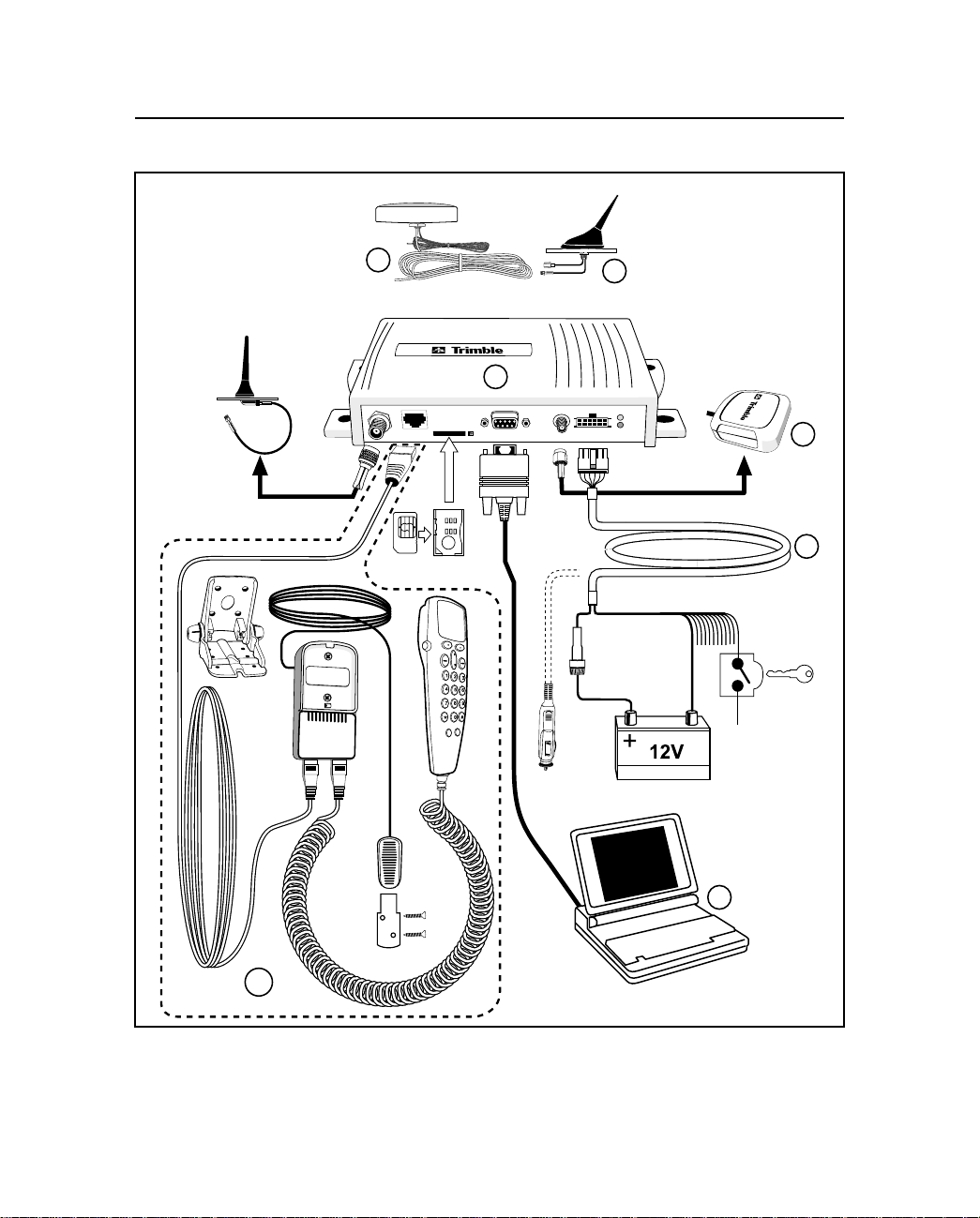
Figure 1-1 CrossCheck GSM System Accessories
CrossCheck GSM Operation Manual 1-3
Page 26

Overview
The callouts in Figure 1-1 are:
1 CrossCheck GSM mobile unit
2 Voice Upgrade Kit including
a. Handset
b. Mounting bracket
c. Handset cradle
d. Hands-free microphone
e. Extension cable
3 Power and discrete I/O cable
4 GPS antenna
5 Laptop (not available from Trimble)
6 Combo GSM/GPS antennas
1.2 CrossCheck GSM Applications
Trimble Mobile Positioning & Communication (MPC) provides you
with the core products around which you can build systems and
applications for managing your transport and logistics assets.
MPC products address the need for an end-to-end solution. They
provide the building blocks at both ends of the asset management
system including the on-board units mounted in the vehicle and the
software installed at the fixed base station.
The on-board components are centered on the CrossCheck GSM, (the
GPS receiver with integrated
can use the CrossCheck GSM as a standalone unit or you can
interface it with external accessories and sensors to make it function
as part of an on-board system.
Optional external units include a Mobile Data Terminal (MDT) to
provide a driver interface to exchange messages or generate manual
1-4 CrossCheck GSM Operation Manual
IQ
Event Engine
and a GSM phone). You
Page 27

event reports, and a handset for use where voice communication is
required.
You can use the Trimble FleetVision software package at the base
station, as a standalone fleet management system or as the
communications platform for an integrated system. FleetVision
features include event and alarm reporting, data handling, as well as
map displays, allowing you to view the positions of mobile assets in
real-time or replayed for analysis purposes. FleetVision includes an
External System Interface (ESI) package. This gives system
integrators and application developers the ability to customize the
system by interfacing to third-party “back office systems” such as
order/stock processing, route optimization systems, and the like.
1.3 CrossCheck GSM Features
The CrossCheck GSM includes these features:
•
Eight channel GPS receiver
•
Configurable, intelligent IQEvent Engine
Overview
(refer to Chapter 5)
•
Slim profile for easy installation
•
One serial port for RS-232 (DCE) serial communications with
data throughput of 300, 600, 1200, 2400, 4800, 9600 (default),
19200, or 38400 bps
•
Extensive discrete I/O (inputs and outputs) for vehicle
peripheral support
•
Optional Voice Upgrade Kit which supports hands-free
operation
•
Password-protected data communications
•
NMEA-0183 Version 2.1 sentence output (see Appendix D for
detailed information)
•
Support for the Trimble Standard Interface Protocol (TSIP),
allowing you to set GPS parameters using the serial port (see
Appendix C for detailed information)
CrossCheck GSM Operation Manual 1-5
Page 28

Overview
•
Support for Trimble ASCII Interface Protocol (TAIP)
•
User-defined parameters:
•
10 destination addresses for outgoing reports
•
50 simple or compound events
•
10 time and distance sets for triggering events
•
50 time windows for triggering events
•
50 region windows for triggering events
•
50 heading windows
•
20 speed limits for triggering events
•
Combination of 10 counters, timers, and distancers
•
Bulkhead and magnetic mount GPS antennas available
•
Data and Event Reporting support by either Circuit Switched
Data mode or Short Message Service (SMS) mode
1-6 CrossCheck GSM Operation Manual
Page 29

1.4 Global Systems for Mobile Communications
Cellular mobile telephone systems have been widely available
throughout the world. However, because cellular mobile telephone
systems are regulated at the national level, these systems are not
generally compatible with each other. To resolve this dilemma of
being able to communicate from almost anywhere, but only within
your own system, The European telecommunications operators (the
Conference of European Postal and Telecommunications
Administration, or CEPT) designed a new mobile telephone network.
This network has evolved into GSM, and CEPT has turned over
management of GSM to the European Technical Standards Institute
(ETSI). GSM is the predominant mobile communications system
throughout Europe and GSM is also widely available throughout the
world.
1.4.1 GSM Cellular Phone System
The Global Standard for Mobile (GSM) protocol offers a variety of
data services that allow users to send and receiv e data at rates of up to
9600 bps. Data may be delivered over ISDN, Packet Switched or
Circuit Switched Data Networks (PSDN or CSDN) and via the Short
Message Service (SMS).
Overview
SMS is a store and forward service for the bi-directional exchange of
alphanumeric messages of up to 160 characters.
Architecture of the GSM network
An Automatic Vehicle Location (AVL) or Asset Management System
based on GSM consists of several distinct components. The
Crosscheck GSM is the mobile unit that is installed in the vehicle and
contains the Subscriber Identity Module (SIM). The SIM card
contains a unique International Mobile Subscriber Identity (IMSI)
number. This enables the network to identify the user and therefore
allow the terminal to have access to specific, subscriber services.
The GSM “cloud” is made up of two sections:
CrossCheck GSM Operation Manual 1-7
Page 30

Overview
•
The Base Station Subsystem that controls the radio link with
the mobiles through local cells
•
The Network Subsystem that controls the switching of calls
between the network users, mobile to mobile, and between
mobile and fixed lines
The Network Subsystem stores all administrative information
including the current cell being used by the mobile unit which allows
call routing and the roaming ability of GSM. An important feature of
GSM is this ability to move across international and network borders,
a feature that is described as “roaming.” If arrangements have been
made with the service provider, the SIM card will be enabled for
roaming.
•
Mobile Station (MS)
•
CrossCheck GSM includes a radio transmitter, receiver
and voice encoder, decoder. The optional Voice Upgrade
Kit includes a handset.
•
Subscriber Identify Module (SIM)—an electronic card
containing a computer chip. The chip contains the
subscriber information and operating system parameters.
SIMs provide authentication, encryption, information
storage, and subscriber account protection services
(including Personal Identification Number or PIN, and Pin
Unblocking Key or PUK). GSM users can move the SIM
from one CrossCheck GSM to another.
• Other network components
• Voicemail System (VMS)— delivers messages and pages
to GSM users.
• Short Message Service Center (SMSC)—delivers text
messages (up to 160 characters) to GSM users.
• Executable Short Message Platform—delivers commands
to the SIM card via an over-the-air interface.
1-8 CrossCheck GSM Operation Manual
Page 31

Overview
• Internetworking Function (IWF)—delivers mobile f ax and
data to GSM users.
CrossCheck GSM Operation Manual 1-9
Page 32

Overview
Mobile Station
Operations and Maintenance Center
Operations Subsystem
Network Subsystem
Crosscheck GSM
Crosscheck GSM
GSM Network
Crosscheck GSM
GSM
Modem
PSTN/ISDN
Base Station
Computer
Mobile Vehicles
Figure 1-2 GSM Cellular Network Topology
1-10 CrossCheck GSM Operation Manual
Page 33

1.5 The Global Positioning System
The Global Positioning System is a satellite-based navigation system
operated and maintained by the U.S. Department of Defense. GPS
consists of a constellation of 24 satellites providing world-wide, 24
hour, three dimensional (3D) cov erage. Although originally concei ved
for military needs, GPS has a broad array of civilian applications
including timing, surveying, fleet management, marine, land, aviation,
and vehicle navigation.
GPS is the most accurate technology available for navigation. As a
satellite based system, GPS is immune from the limitations of land
based systems, which have limited coverage and whose accuracy
varies with geographic location and, even under ideal conditions,
cannot compare with GPS.
By computing the distance to GPS satellites orbiting the earth, a GPS
receiver can calculate an accurate position. This process is called
satellite ranging. GPS receivers can also provide precise time, speed,
and course measurements which are important for vehicle mobile
positioning and communications applications.
Overview
1.6 GPS Receiver
The CrossCheck GSM includes an advanced GPS receiver, which
provides the position, course, speed and time information required for
AVL and fleet management applications. A brief o v ervie w of the GPS
receiver’s architecture and operation is provided below.
The CrossCheck GSM’s GPS receiver features an eight-channel
digital signal processor (DSP) which operates at the GPS L1
frequency (1575.42 MHz) and processes the AcquisitionCoarse/
Acquisition
(C/A) code portion of the GPS signal. The RF and digital signal
processing components of the GPS module are custom ASICs
designed by Trimble.
CrossCheck GSM Operation Manual 1-11
Page 34

Overview
1.7 GSM Operation
At power up the CrossCheck GSM automatically searches for a GSM
network using a set of tables on the SIM card to determine which
GSM network the phone should try to reach. These tables are the
Public Land Mobile Network (PLMN) tables and each GSM network
has its own unique PLMN number. This number is the Mobile
Country Code (MCC) and the Mobile Network Code (MNC), which
are also the first numbers of the subscriber’s IMSI. (The IMSI is the
MCC, plus the MNC, plus the MSIN.)
The PLMN table finds either the subscriber’s home network or a
network that will allow service, and registers to the network
consistent with the handset. The responding network’s MSC passes
this request for service to the VLR. If the VLR has information about
this IMSI, then it passes the request to the AUC for authentication. If
the VLR cannot find any information on this IMSI, it must pass the
request to the HLR and get approval before passing on the request.
Once the VLR has approval to grant the request for service, it knows
the user identity, what features are authorized, and the authentication
codes (from the AUC). The VLR then passes the request back to the
MSC for routing to the number being called.
If the number being called is a land-based number, the MSC passes
the call to the Public Switched Telephone Network (PSTN) for
connection. If the number being called is another mobile number, the
MSC repeats the process described above to locate the number being
dialed. Depending on services supported, the call will be answered, be
routed to voicemail, be intercepted by a live answering service, or
simply time out with the message that the number being dialed is not
available. In any case, the transmission is digital and encrypted so
information cannot be intercepted easily.
1-12 CrossCheck GSM Operation Manual
Page 35

2 Installation
Instructions for installing the CrossCheck GSM mobile unit in the
vehicle are introduced in this chapter. This chapter covers:
• Unpacking the CrossCheck GSM
• Installer supplied parts
• Mounting the CrossCheck GSM
• Mounting the GPS and GSM cellular antennas, and routing the
antenna cables
• Connecting laptop computers, Windows CE devices, and other
ASCII peripherals to the MDT/Aux port
• Connecting discrete input and output leads
• Connecting power
• Mounting and connecting the Cellular Handset, hands-free
cradle, and remote microphone
• Inserting the SIM
The CrossCheck GSM can be installed before or after configuring its
IQEvent Engine. For example, you might want to configure all of the
CrossCheck GSM units for a fleet of vehicles on a bench prior to
installation. If you prefer to configure the CrossCheck GSM first, read
Chapter 3, Configuration, before installing the CrossCheck GSM.
CrossCheck GSM Operation Manual 2-1
Page 36

Installation
Note – If you plan to install the CrossCheck GSM before configuring
the unit, be sure to leave adequate clearance to the MDT/Aux port
and other connectors. Adequate clearance must exist to connect a
laptop or Mobile Data Device to the unit, and you must be ab le to read
the LED indicators if troubleshooting is required.
2.1 CrossCheck GSM Connections
This sections shows the CrossCheck GSM components connections.
Figure 2-1 shows the CrossCheck GSM connections.
2
1
3
1. GSM Antenna
2. Hands-free cradle
3. SIM slot
4. MDT/Aux
5.GPS Antenna
6. Power and Discrete I/O
4
5
6
Figure 2-1 CrossCheck GSM Connectors
2-2 CrossCheck GSM Operation Manual
Page 37

2.1.1 GSM Antenna
The GSM antenna uses a mini-UHF connector. For more
information, see Appendix A, Specifications.
2.1.2 Power and Discrete I/O Pinout
Table 2-1 indicates how the power and discrete I/O cable carries
signals.
Table 2-1 Power and Discrete I/O Pinout
Pin Signal Function
1V
2 GND Ground
3 CHAS Chassis Ground
4 GND Ground
5 IGN Input: Ignition Sense
6 IP3 Discrete Input 3
7 IP2 Discrete Input 2
8 XP2 Low-side Driver 2
9 IP1 Discrete Input 1
10 XP1 Low-side Driver 1
11 IP0 Discrete Input 0
12 XP0 Low-side Driver 0
BATT
Installation
Input: Power 9-32V
CrossCheck GSM Operation Manual 2-3
Page 38

Installation
Figure 2-2 Power and Discrete I/O Pinout
2.1.3 GPS Antenna
The GPS antenna uses an SMA female connector. For more
information see Appendix A, Specifications, Table A-4.
2.1.4 MDT/Aux Port
Table 2-3 illustrates the MDT port pin configuration.
12111098765432
1
5 4 3 2 1
9 8 7 6
MDT/Aux
Figure 2-3 MDT/Aux Pinout
2-4 CrossCheck GSM Operation Manual
Page 39

Table 2-2 shows the MDT connector pin-out.
Table 2-2 MDT Connector Pin-out
Pin # Signal Connection
1 DCD Output: Carrier Detect
2 RxD Output: Serial Data
3 TxD Input: Serial Data
4 DTR Input: Data Terminal Ready
5 GND Ground
6 DSR Output: Data Set Ready
7 RTS Input: Request to Send
8 CTS Output: Clear to Send
9 RI Output: Always inactive (not supported)
2.2 Inspecting and Unpacking the Shipment
The CrossCheck GSM may arrive in one or more cartons, depending
on the number of units and the options ordered with the shipment.
Before opening the shipping containers, inspect the cartons for
punctures or damage and immediately report any problems found to
the shipping carrier. Then open the shipping cartons individually, and
check their contents against the packing slip.
Installation
Table 2-3 identifies the CrossCheck GSMs and bundles, and the
components included.
Table 2-3 CrossCheck GSM Units and Bundles
Part No. Description
43455-01 CrossCheck GSM Mobile Unit (includes GPS
antenna, power and I/O cable, manual, handset
quick reference, and the Voice Upgrade Kit).
43455-11 CrossCheck GSM Mobile Unit 10 Unit Bundle
(includes 10 CrossCheck GSMs, without GPS
antennas or accessories.
CrossCheck GSM Operation Manual 2-5
Page 40

Installation
Additional cartons may be included in the shipment for GPS and
cellular antennas, interface cables, and Voice Upgrade Kit options.
For a complete listing of CrossCheck GSM unit and component part
numbers, see CrossCheck GSM Part Numbers on page A-12.
2.3 Installer Supplied Parts
The following parts must be supplied by the installer:
• Mounting fasteners for the CrossCheck GSM.
• Fasteners for mounting the GPS antenna if the antenna is the
bulkhead type.
• Cable ties for securing cables to the vehicle.
• Any special connectors and adapters required to connect
interface devices and power leads—the power and I/O cable is
supplied with the CrossCheck GSM PN 43455-01 only.
• Subscriber Identity Module (SIM) cards.
• GSM antenna.
• GPS antenna (supplied with the CrossCheck GSM (PN 43455-
01 only).
2.4 Mounting the CrossCheck GSM
The CrossCheck GSM can be installed inside any type of vehicle and
in any orientation. It can be installed in an enclosed compartment or
in a location with limited accessibility as long as the environmental
specifications are maintained to ensure reliable operation. For
example, the CrossCheck GSM can be installed on the floor under a
seat or on a wall behind a seat. (The CrossCheck GSM cannot be
installed inside the engine compartment, wheel well, chassis, or on
any exterior surface of the vehicle.)
Choose a location for the CrossCheck GSM which allows for
convenient routing and connection of the antenna and interf ace cables,
2-6 CrossCheck GSM Operation Manual
Page 41

Installation
and which has access to a power source. When selecting a mounting
location, consider the specifications listed in Appendix A, Table A-8,
and avoid the following hazards:
• Direct exposure to weather
• Excessive heat (for example, exhaust manifolds)
• Excessive cold (for example, refrigeration units)
• High vibration areas (engine compartment, transmission)
• Corrosive fluids and gases (acids, petroleum products)
• Direct exposure to water (the CrossCheck GSM is not
waterproof)
To mount the CrossCheck GSM:
1. Choose the mounting location. The CrossCheck GSM can be mounted horizontally, vertically,
or in any convenient orientation protected from moisture.
During normal system operation, the user does not need to see
the CrossCheck GSM LED indicators. However, the ability to
see the LED indicators is a definite advantage when
troubleshooting the unit.
The integral mounting flange is designed to secure the
CrossCheck GSM to a flat surface. The flange has four holes
for securing the unit with fasteners.
2. Use self tapping screws or machine scre ws to secure the unit to
the mounting surface. Figure 2-4 shows the mounting
dimensions.
CrossCheck GSM Operation Manual 2-7
Page 42

Installation
205.5
4.8
69.9
Figure 2-4 CrossCheck GSM Mounting Dimensions (in millimeters)
The installer must provide an appropriate selection of fasteners
to secure the CrossCheck GSM to the mounting surface.
a. When using self-tapping screws, select an appropriate size
and length for the mounting surface. The hole size leaves
some allowance for holes drilled slightly off center from
the specified dimensions.
b. When using machine screws, select a screw length which
extends a safe distance beyond the mounting surface, and
secure the screw with a washer and nut. Lock washers are
recommended to prevent vehicle vibration from loosening
the fasteners.
In general, Trimble Navigation recommends the use of number
m3.5 (or number 6) pan head machine screws.
2-8 CrossCheck GSM Operation Manual
Page 43

Installation
Caution – Use washers sized small enough that they do not tighten
down on the plastic cover of the CrossChec k GSM when the mounting
screws are secured. Otherwise, over stressing the plastic mounting
surface when tightening the mounting screws can cause the plastic to
crack. Tightening screws without using washers can lead to
compressing, cracking, or deforming the mounting surface.
2.4.1 Connecting CrossCheck GSM to the Vehicle Chassis
For proper operation, the aluminum chassis of the CrossCheck GSM
must be connected electrically (grounded) to the chassis of the vehicle
on which it installed. This can be accomplished by:
• Direct connection through metal screws (preferred), or
• Using the chassis ground wire
Direct Connection through Mounting Screws
Mount the CrossCheck GSM mobile unit on a metal surface that is
permanently attached to the vehicle chassis (for example the base of
the trunk, or a mounting plate that is permanently attached to the
chassis using metal screws). Fasten down the CrossCheck GSM
mobile unit using metal screws driven through the metal tabs on the
sides of the unit. Make sure the screws are tight, and that they make
contact both with the metal on the CrossCheck GSM and with the
vehicle chassis. Use star washers to ensure a reliable electrical contact
to the metal tabs.
Note – If this direct connection through mounting screws method is
used for chassis connection, then the chassis ground (pin 3 on the
power and discrete I/O connector) on CrossCheck GSM should be left
unconnected.
CrossCheck GSM Operation Manual 2-9
Page 44

Installation
Connection through the Chassis Ground Wire
If the CrossCheck GSM unit cannot be mounted directly on a metal
surface that is attached to the vehicle, then use the chassis ground wire
(pin 3 on the power and discrete I/O connector) to make electrical
contact to the vehicle chassis. Use a wire with gauge of at least 18
AWG to connect the CrossCheck GSM power connector to the
vehicle chassis. Keep the wire length as short as possible by selecting
a connection point in the vehicle chassis that is close to the
CrossCheck GSM unit. Use a metal screw with a star washer to ensure
a reliable electrical contact to the vehicle chassis.
2.5 Choosing the GPS Antenna Mounting Location
Antenna location is critical for optimum GPS performance. Choose a
location for the GPS antenna with an unobstructed view of the sky,
and which is safe from damage during normal vehicle operation and
maintenance. GPS satellite signals do not penetrate metal or dense
wood. GPS signals can penetrate plastic, glass and tinted glass (except
metalized glass), fiberglass and plexiglass materials as long as the
surface is relatively dry.
Caution – Never mount the GPS antenna under a metalized glass
windshield, such as those used in some vehicles for window
de-fogging or de-icing systems. The GPS antenna can be mounted
under a tinted-glass windshield.
When selecting a location for the GPS antenna, ensure that the
antenna is not shielded from satellite signals by metal objects or other
impenetrable materials. For optimal GPS performance, the antenna
location should have a clear view of the sky.
2-10 CrossCheck GSM Operation Manual
Page 45

Installation
Disclaimer — The instructions included in this section apply to the
GPS antennas sold by Trimble and may not apply to third-party
products. There are many other GPS antennas available on the
market which may or may not be compatible with the CrossCheck
GSM, including combined GPS/GSM cellular antenna solutions which
have not yet been tested and certified by Trimble.
Mount the antenna in a horizontal position (see Figure 2-5 on page
2-12), facing the sky. If the antenna must be located in the vicinity of
other antennas (radio, cellular phone), locate the GPS antenna at least
46 centimeters (approximately 18 inches) away. Avoid areas of high
vibration (for example, engine hoods). For permanent installations,
choose a location with access both above and below the antenna
mounting surface. This access is required for installing fasteners and
for routing the antenna cable.
Note – The standard length of magnetic mount and bulkhead-mount
GPS antenna cables supplied by Trimble is 5 meters (or
approximately 16 ft.). Longer bulkhead-mount antenna cables can be
prepared by the installer using the guidelines presented in
Appendix A, Specifications.
Since GPS satellite signals can penetrate plastic, fiberglass and glass,
the GPS antenna can also be installed on a dashboard under a sloped
windshield (if the windshield is not metallized) or under a plastic
fender or bumper. These alternative locations are likely to offer less
satellite coverage, since the metal components of the vehicle shield
the antenna from portions of the sky.
CrossCheck GSM Operation Manual 2-11
Page 46

Installation
Figure 2-5 shows typical antenna mounting locations for an
automobile.
Arrows show acceptable places
to mount the GPS antenna
1
2
1
2
1 2
Best Performance - outside installations
with an unobstructed view of the sky
are the best mounting locations.
2
The GPS antenna can be installed
inside the vehicle under the front or
back windshield if the glass is not
metallized.
1
Reduced Performance - interior mounting
locations and bumper mounting locations
are acceptable, but may not provide a
clear, unobstructed view of the sky.
Figure 2-5 Antenna Mounting Locations for Automobile
2
2-12 CrossCheck GSM Operation Manual
Page 47

Installation
Figure 2-6 shows the typical antenna mounting locations for a van.
Best Performance - the GPS antenna
1
should be mounted in a locationwith a
clear unobstructed view of the sky.
3
1
2
Reduced Performance - avoid locations
where the antenna does not have a
clear unobstructed view of the sky.
3
Unacceptable Location
2
Figure 2-6 Antenna Mounting Locations
CrossCheck GSM Operation Manual 2-13
Page 48

Installation
The antenna can be mounted under a fiberglass wind deflector such as
those used on conventional and cabo ver trucks (see Figure 2-7). Make
sure the wind deflector is not painted with a metallic finish.
Note: Must be
fiberglass
Figure 2-7 Antenna Mounted under Fiberglass Canopy
Note – The GPS antenna ma y be subject to perf ormance degradation
when covered by a heavy layer of snow or ice. If these are typical
conditions for your application, mount the antenna in an accessible
location, so snow can be easily removed.
The CrossCheck GSM can receive GPS signals from one of two types
of optional Miniature BulkHead GPS antennas or a Miniature
Magnetic GPS antenna, all available from Trimble. Follow the
applicable procedure (below) to mount the GPS antenna.
2-14 CrossCheck GSM Operation Manual
Page 49

2.5.1 Miniature BulkHead GPS Antenna with Flange
(P/N 31192-00)
A straight TNC-Plug to SMA-Plug antenna cable (P/N 36107) or
right-angle TNC-Plug to straight SMA-Plug antenna cable (P/N
36106) is available for the Miniature Bulkhead Antenna with Flange.
For more information, see Appendix A, Specifications.
Figure 2-8 shows the Miniature Bulkhead GPS antenna mounting.
Mounting Lug
Gasket
Installation
Cable
Mounting hardware.
Only two of four sets
shown for clarity.
Figure 2-8 Miniature Bulkhead GPS Antenna with
Flange (P/N 31192-00)
CrossCheck GSM Operation Manual 2-15
Page 50

Installation
To mount the Miniature Bulkhead GPS Antenna with Flange:
1. Drill holes in the mounting surface using the antenna mounting template shown in Figure 2-9.
19 mm
(0.75 in)
7.6 cm
(3.0 in)
3.8 mm
(0.15 in)
Figure 2-9 Mounting Hole Dimensions
2. Slip the antenna through the larger hole in the center of the hole
pattern and rotate the antenna until the four holes in the antenna
mounting flange are aligned to the hole circle.
3. Secure the antenna with the four screws, lock washers and nuts.
4. Connect the TNC connector on the antenna cable to the TNC
connector on the antenna, and route the cable to the
CrossCheck GSM mounting location. Use cable ties to secure
the cable along the routing path. For detailed cable routing
guidelines, see Routing the GPS Antenna Cable on page 2-20.
2-16 CrossCheck GSM Operation Manual
Page 51

Installation
2.5.2 Miniature Bulkhead GPS Antenna without Flange
(P/N 32434)
A straight TNC-Plug to SMA-Plug antenna cable (P/N 36107) or
right-angle TNC-Plug to straight SMA-Plug antenna cable (P/N
36106) is available for the Miniature Bulkhead Antenna without
Flange. For more information, see Appendix A, Specifications.
The metal thickness at the mounting location should be checked
before drilling the mounting hole. The bulkhead mount on the
antenna is designed to attach to metal surfaces with a thickness of
48 mm (0.1875) inches or less.
Gasket
Sheet Metal
Metal Washer
Mounting Nut
Jam Nut
Figure 2-10 Miniature Bulkhead GPS Antenna without
Flange (P/N 32434)
CrossCheck GSM Operation Manual 2-17
Page 52

Installation
To mount the antenna:
1. Choose the antenna mounting location (see Choosing the GPS
Antenna Mounting Location on page 2-10).
2. Drill a 19 mm (0.75 inch) hole at the mounting location.
3. Remove the large nut from the bottom of the antenna.
4. Mount the gasket as shown in Figure 2-10.
5. Slip the antenna through the mounting hole, and secure it with the large nut.
6. Connect the antenna cable as shown in Figure 2-10.
7. Route the cable to the CrossCheck GSM mounting location,
and connect the cable to the GPS Antenna connector. Use cable
ties to secure the cable along the routing path. For detailed
cable routing guidelines, see Routing the GPS Antenna Cable
on page 2-20.
2-18 CrossCheck GSM Operation Manual
Page 53

2.5.3 Miniature Magnetic GPS Antenna (P/N 37167)
The Miniature Magnetic Antenna features a magnetic mount for
attaching the unit to ferrous metal surfaces and an integral 5 meter
cable with SMA connector.
Figure 2-11 Miniature Magnetic GPS Antenna
To mount the Magnetic GPS Antenna:
1. Choose the antenna mounting location (see Choosing the GPS
Antenna Mounting Location on page 2-10).
Installation
2. Mount the antenna to a ferrous surface. The antenna can be
mounted on the exterior of the vehicle or in the vehicle’s
interior.
3. Route the antenna cable. The antenna features a permanent
antenna cable which must be routed to the location where the
CrossCheck GSM is mounted. For detailed cable routing
guidelines, see Routing the GPS Antenna Cable on page 2-20.
Caution – The magnetic-mount antenna cable is exposed to the
environment. Since wind could cause the cable to whip around, use
tie wraps to secure the cable along its route.
CrossCheck GSM Operation Manual 2-19
Page 54

Installation
Caution – The magnetic-mount antenna cable has no strain relief at
the antenna end of the cable and is not recommended for permanent
installations.
2.6 Routing the GPS Antenna Cable
The Magnetic GPS Antenna has an integral antenna cable, and the
Miniature Bulkhead GPS Antennas have a separate 5 meter (or
approximately 16 ft.) cable. If you are using one of the Miniature
Bulkhead GPS Antenna units, attach the antenna cable to the SMA
connector on the base of the antenna prior to routing the cable. When
routing the cable, start at the antenna and choose the most direct path
to the CrossCheck GSM while avoiding the following hazards:
• Make sure that at least two inches of clearance exists between
the CrossCheck GSM’s Antenna connector and the nearest
obstacle.
• Make all cable bends, especially the bend at the SMA strain
relief to the Antenna connector, with at least one-half inch bend
radius.
• Provide an adequate service loop when routing the cable
around vehicle hinges to ensure that the cable is not
inadvertently pinched when a hinged door opens or closes.
• Make sure that the coax cable is not routed through areas where
vehicle movement can abrade the cable surface.
• Never coil the excess antenna cable, particularly the Magnetic
GPS antenna cable. A coiled cable can act as an antenna and
may receive interference.
• Protect cables from exposure to corrosive fluids.
Once the cable is routed and secured, attach the cable to the
CrossCheck GSM GPS (SMA) connector.
2-20 CrossCheck GSM Operation Manual
Page 55

Installation
2.7 Choosing a GSM Antenna Mounting Location
Although not as critical as GPS antenna placement, cellular antenna
placement is also important. Mount the cellular whip antenna in a
vertical orientation in a location where it is safe from damage during
normal vehicle operation and maintenance. Automated vehicle
washes may damage misplaced cellular antennas.
If you are installing multiple antennas, maintain a separation of at
least 46 centimeters (or approximately 18 in.) between the cellular (or
other) and GPS antennas (see Figure 2-12). If you are using a
combination GPS/cellular antenna, maintain a separation of at least
46 centimeters (or approximately 18 in.) between the combination
antenna and any other antennas.
46cm
GPS
Antenna
(18 in)
minimum
Cellular
Antenna
Figure 2-12 Distance Between Antenna Locations
In general, the farther the separation, the less chance of interference.
For permanent antenna installations, choose a location with access
CrossCheck GSM Operation Manual 2-21
Page 56

Installation
both above and below the antenna mounting surface. This access is
required for installing fasteners and for routing the antenna cable.
Cellular phone dealers and installers are experts on cellular antenna
placement. For some installations, the installer can substitute a glassmount antenna as long as it conforms to the requirements listed in
Appendix A, Specifications.
2.7.1 Routing the GSM Antenna Cable
The next step in the installation process is routing and connecting the
antenna cable to the CrossCheck GSM. When routing the cable, start
at the antenna and choose the most direct path to the CrossCheck
GSM while avoiding the following hazards:
• Sharp bends or kinks in the cable.
• Excessive heat.
• Exposure to corrosive fluids.
• Never coil the excess antenna cable, particularly the cellular
antenna cable. A coiled cable can act as an antenna and may
receive interference.
• Provide an adequate service loop when routing the cable
around vehicle hinges to ensure that the cable is not
inadvertently pinched when a hinged door opens or closes.
• Make sure that the coax cable is not routed through areas where
vehicle movement can abrade the cable surface.
Caution – If your cellular antenna cable is exposed to the
environment, wind could cause the cable to whip around. Use tie
wraps to secure the cable along its route.
Caution – A minimum separation distance of 20 cm must be maintained between the antenna and
persons for this device to satisfy the RF Exposure requirements of the FCC. For fixed mount operation,
the antenna co-location requirements of Section 1.1307(b)(3) of the FCC rules must be satisfied.
For fixed mount operation, the maximum gain of the antenna must not exceed 7 dBi. For mobile
operation, the maximum gain of the antenna must not exceed 3 dBi.
WARNING! Use of this unit in portable operations is not permitted.
2-22 CrossCheck GSM Operation Manual
Page 57

2.7.2 Connecting the Magnetic GSM Antenna Cable
After routing the GSM antenna cable, connect the cable to the
mini-UHF connector. Tighten the connector firmly to prevent
loosening caused by normal vehicle vibration.
2.7.3 Connecting the Permanent-Mount GSM Cable
Once the cable routing is complete and the cable is secured attach the
mini-UHF connector on the antenna cable. Then attach the cable
to the GSM connector on the front panel of the
CrossCheck GSM.
Installation
CrossCheck GSM Operation Manual 2-23
Page 58

Installation
2.8 Connecting the Power and I/O Cable
The power and I/O cable (P/N 40358) is a flexible interface for
connecting power and a variety of input and output peripherals to the
CrossCheck GSM (see Figure 2-13).
2
4
8
10 12
6
11
9
57
3
1
Front View
Side View
Molex Micro-Fit 3.0 12-Pin
Connector
Molex P/N 43025-1200
Pins
Molex female
templated contact
Molex P/N 43030-0001
36
Batt. GND
Chassis GND
AGC 2A@250V
6
V
batt
GND
IGN
IP3
IP2
XP2
IP1
XP1
IP0
XP0
Figure 2-13 Power and I/O Cable
The power and I/O cable is 91 cm (3 ft.) long with 12 wire leads and
connects to the CrossCheck GSM’s I/O port.
1.
Trimble also supplies a power -only cable (not combined with I/O), for use
with cigarette lighters (P/N 43505).
1 Vbatt Red Input Power 9-32V
2 GND Black Batt. GND
3 GND Green Chassis GND
4 GND Blk/White GND
5 IGN White Ignition Sense Input
6 IP3 Blue Input 3
7 IP2 Purple Input 2
8 XP2 Orange Low Side Driver 2
9 IP1 Yellow Input 1
10 XP1 Gray Low Side Driver 1
11 IP0 Purple/White Input 0
12 XP0 Brown Low Side Driver 0
1
2-24 CrossCheck GSM Operation Manual
Page 59

Table 2-4 provides pin-out information for the I/O cable. Each of the
connections is briefly described in Table 2-4 and more detailed
descriptions of each cable lead follow the table.
Table 2-4 Power/Interface Cable Pin-Out
Pin # Signal Function
1V
Batt
2 GND Ground
3 CHAS Chassis Ground
4 GND Ground
5 IGN Input: Ignition Sense
6 IP3 Discrete Input 3
7 IP2 Discrete Input 2
8 XP2 Low-side Driver 2
9 IP1 Discrete Input 1
10 XP1 Low-side Driver 1
11 IP0 Discrete Input 0
12 XPO Low-side Driver 0
Input: Power 9-32V
Installation
If you want to make your own power and I/O cable, refer to Figure
2-2 for information on the specifications for the cable connectors
(Molex
®
P/N 43025-1200) and contacts (Molex P/N 43030-0001).
Please include a 2A fuse connected to Pin 1.
CrossCheck GSM Operation Manual 2-25
Page 60

Installation
2.8.1 Inputs (IP0 to IP3)
The CrossCheck GSM unit supports four discrete inputs. The circuit
diagram is shown in Figure 2-14.
3.3V/10m/A
330K
Input
3K
470pf
100K
1.0µF
To logic
Figure 2-14 Input Circuit Diagram
Input Logic High: Open circuit or Vin > 2.4 VDC
Input Logic Low: Vin < 0.6 VDC
The inputs must remain in either state for at
least 200 milliseconds before the CrossCheck
GSM detects the input.
Input Current
(Max)
Iin < 3 milliamps
1 milliamp is typical at 12V.
Input Protection: Protected up to at least VBatt continuous
Each input floats to a logic high state (inactive) when left open.
Grounding an input causes a logic low state (activ e). The CrossCheck
GSM can be configured to detect either logic high or logic low states
at the inputs whenever the unit is powered on.
2-26 CrossCheck GSM Operation Manual
Page 61

Note – The CrossCheck GSM can be configured to detect only a logic
low (grounded) input when it is powered off and in power
management mode.
The discrete inputs are compatible with properly connected relays and
switches or with standard 3.3 volt logic levels. A properly connected
relay or switch allows the input to float high in one position and
grounds the input in the other position.
The input must be held in a particular logic state for at least 200 msec
(configurable up to 1 second) so the CrossCheck GSM can detect it.
2.8.2 Outputs (XP0 to XP2)
The CrossCheck GSM features three discrete outputs (XP0-XP2) for
driving external devices such as relays. When inactive (default state),
the discrete outputs are tied to vehicle battery voltage (nominally 12
VDC) through a 15 kOhm resistor. When active, the outputs are
shorted to ground through a bipolar junction transistor. In the active
(low) state, the outputs can sink up to 200 milliamps. Figure 2-15
shows a diagram of a discrete output.
Installation
CrossCheck GSM Operation Manual 2-27
Page 62

Installation
Vbatt
15K
0.2A
Output
36V
0.01uF
470pf
Figure 2-15 Output Circuit Diagram
Output Inactive: 15 kOhms through V
vehicle-battery
Output Active: Tied to ground through a saturated bipolar
junction transistor, V
200 milliamps; V
1.5 VDC at
out
< 0.5 VDC at
out
10 milliamps
Output Protection: Protected against direct shorts to ground
Output Sink Current
Up to 200 milliamps
Capability
,
For more information about discrete outputs, refer to the TAIP/
IQEvent Engine Reference Manual, section 2.5, “Digital Inputs and
Outputs.”
2-28 CrossCheck GSM Operation Manual
Page 63

Installation
2.9 Connecting a Computer or Mobile Data Device with the Serial I/O Cable
The D-9 connector is an RS-232 (receptacle) DCE (Data
Communication Equipment) serial port, making it compatible with
most personal computers and Mobile Data Devices.
You can configure the MDT/Aux port with the TAIP MT command.
(For more information on TAIP commands, refer to the TAIP/IQEvent
Engine Reference Manual.)
The MDT port supports the following modes:
• Normal—Supports any combination of TAIP, TSIP, and NMEA
protocols
• PAD—All input is converted into TAIP TX messages, all
output is text stripped from TX messages
• AT—Traffic consists of AT commands and data from the MDT
device to GSM, and GSM responses to the MDT device from
the CrossCheck GSM
The MDT inputs (Rx) accept
–3 to –15 VDC. A low input signal is
less than -3VDC (typical). A high input signal is greater than+3VDC.
The MDT outputs (Tx) range from
–5 volts to –8 volts, depending on
the load.
Note – During normal operation, the MDT/Aux service port
communicates with a PC or Mobile Data Device using TAIP messages
(see Chapter 5, IQEvent Engine Overview and the IQEvent Engine/
TAIP Reference Manual for detailed information) at 9600 bps, 8-N-1,
and no flow control. The baud rate and other communications
parameters can be set to match the PC or Mobile Data Device
settings.
Figure 2-16 shows the cable connections between a PC and the
CrossCheck GSM.
CrossCheck GSM Operation Manual 2-29
Page 64

Installation
Crosscheck GSM
MDT/Aux Port
To Serial Port
on Laptop
Serial I/O
Cable
Figure 2-16 PC to CrossCheck GSM Connections
2-30 CrossCheck GSM Operation Manual
Page 65

2.10 CrossCheck GSM Power
The CrossCheck GSM operates on input voltages from 9-32 VDC.
The low noise amplifier integrated on the GPS antenna draws power
from the CrossCheck GSM through the antenna cable. The
CrossCheck GSM does not require any special power up or down
sequencing.
The CrossCheck GSM’s power circuitry is designed to protect the
unit from random power fluctuations and conditions. Input circuits
protect against transient voltage spikes found in most auto and truck
environments. An external fuse protects against excessive current.
See Appendix A, Specifications, for more information on the
CrossCheck GSM power requirements.
Installation
CrossCheck GSM Operation Manual 2-31
Page 66

Installation
Figure 2-17 shows the power and I/O cable.
2
4
8
6
57
3
1
Front View
Side View
36
Batt. GND
Chassis GND
AGC 2A@250V
6
V
batt
GND
IGN
IP3
IP2
XP2
IP1
XP1
IP0
XP0
1 Vbatt Red Input Power 9-32V
2 GND Black Batt. GND
3 GND Green Chassis GND
4 GND Blk/White GND
5 IGN White Ignition Sense Input
6 IP3 Blue Input 3
7 IP2 Purple Input 2
8 XP2 Orange Low Side Driver 2
9 IP1 Yellow Input 1
10 XP1 Gray Low Side Driver 1
11 IP0 Purple/White Input 0
12 XP0 Brown Low Side Driver 0
10 12
9
11
Molex Micro-Fit 3.0 12-Pin
Molex P/N 43025-1200
templated contact
Molex P/N 43030-0001
Connector
Pins
Molex female
Figure 2-17 I/O Power Cable (P/N 40352)
Note – Trimble recommends installing the power and ground leads as
close to the battery as possible to ensure that the CrossCheck GSM
is connected to the cleanest source of power possible.
2-32 CrossCheck GSM Operation Manual
Page 67

Installation
The CrossCheck GSM is protected against both input power overvoltage and reverse polarity. The primary power cable has a built-in 2amp fuse. The DC ground line connects to the vehicle’s DC ground.
The Ignition Sense lead, if connected to a source of ignition switched
battery voltage, senses when the vehicle’s ignition is active. There are
three connection options for connecting the Power, Ground, and
Ignition Sense wires. These options are described in the next three
sections.
Note – The CrossCheck GSM (including the cellular phone) will power
down automatically when input voltage drops below 9V or exceeds
32V, see the input power specification in Appendix A. IQEv ent Engine
signals for under- and over-voltage are available, with default values
of 9.5V and 31.5V respectively.
For configurations, refer to the TAIP PM message description in the
TAIP/IQEvent Engine Reference Manual.
CrossCheck GSM Operation Manual 2-33
Page 68

Installation
2.10.1 Connections For Power Management
For the Power Management configuration, the CrossCheck GSM
operates and draws power (150 milliamps nominal) continuously only
when the vehicle is running. When the ignition is of f, the CrossCheck
GSM responds to the change in the state of the Ignition Sense lead
and goes to sleep (at programmed intervals), drawing reduced power
(<10 milliamps).
When IQEvent Engine is configured for power management, the
CrossCheck GSM can be scheduled to wake up periodically, typically
long enough to refresh its GPS position) or could wake up when
triggered by an external signal or GSM Ring, and then go back to
standby mode. Therefore, even though the CrossCheck GSM is
drawing power while awake, its duty cycle is a fraction of what it
would be under continuous power, and battery life is extended. For
additional information, refer to PM Message in the TAIP/IQEvent
Engine Reference Manual.
2-34 CrossCheck GSM Operation Manual
Page 69

To
Crosscheck
GSM
Power and I/O
V
batt
Installation
Cable
Red
BATT. GND
CHASSIS GND
GND
IGN
IP3
IP2
XP2
IP1
XP1
IP0
XP0
Black
Green
White
Figure 2-18 Power Management Power Connections
To install the power cable for use with the Power Management
feature:
1. Connect the primary power line to a non-switched/continuous
source of DC power, such as the vehicle’s battery.
2. Connect the Ignition Sense line to ignition switched battery
power, so that this line is active when the ignition is on.
CrossCheck GSM Operation Manual 2-35
Page 70

Installation
Note – For the Power Management mode, make sure that the
Command parameter is set to ‘A’ using the PM message (refer to PM
Message in the TAIP/IQEvent Engine Reference Manual). Power
Management is disabled (Command parameter is set to ‘D’) by default
which is equivalent to the Continuous Power mode (see below).
2.10.2 Continuous Power Connection (No Power Management)
For the Continuous Power configuration (see Figure 2-19), the
CrossCheck GSM operates and draws power continuously, (150
milliamps is typical without the Voice Upgrade Kit, 325 milliamps is
typical with the Voice Upgrade Kit) even when the vehicle is not
running.
2-36 CrossCheck GSM Operation Manual
Page 71

To
Crosscheck
GSM
Power and I/O
V
batt
Installation
Cable
Red
BATT. GND
CHASSIS GND
GND
IGN
IP3
IP2
XP2
IP1
XP1
IP0
XP0
Black
Green
White
Figure 2-19 Continuous Power Connections
To connect the power cable to continuous power:
First connect the primary power line, then connect the ignition sense
line to a non-switched/continuous source of DC power, such as the
vehicle’s battery.
CrossCheck GSM Operation Manual 2-37
Page 72

Installation
Note – With the Continuous Power Configuration, the CrossCheck
GSM may drain the car battery in 1 to 3 weeks, depending on battery
quality and remaining life span, and if the vehicle is not operating
during the entire time. Observe extreme care when using this
connection option. The CrossCheck GSM will automatically power off
when the voltage drops below 9 VDC.
2.11 Installing the CrossCheck GSM Voice Upgrade Kit
The Voice Upgrade Kit (P/N 43456) includes the items shown in
Figure 2-20.
RJ-45 10-pin Extension Cable
Fasteners
Microphone
Handset Cradle
Handset
Cradle Mounting
Figure 2-20 Voice Upgrade Kit Components
2-38 CrossCheck GSM Operation Manual
Page 73

Installation
Use the RJ-45 Extension Cable to connect CrossCheck GSM the
cradle.
To perform the installation, the following components from the Voice
Upgrade Kit are used:
• Handset
• Cradle Mounting Bracket
• 5 meter (or approximately 16 ft.) RJ-45 Extension Cable for
connecting to the CrossCheck GSM
• Microphone
• Handset Cradle
• Mounting Fasteners
As an example, Figure 2-21 shows the typical cable interconnection
scheme between a CrossCheck GSM mounted in a car trunk with the
RJ-45 Extension Cable.
GPS
Antenna
Crosscheck
GSM
Cellular
Antenna
Handset
and
Cradle
Microphone
Figure 2-21 Typical Voice Upgrade Kit Installation for Car with the
CrossCheck GSM Mounted in Trunk
CrossCheck GSM Operation Manual 2-39
Page 74

Installation
Installer-Supplied Components
The parts listed in Table 2-5 must be supplied by the installer.
Table 2-5 Items Supplied by Installer
Qty Item Supplied by Installer
1 Mounting Stand (if necessary)
varies Appropriate Screws for installing the Mounting Stand
2.11.1 Mounting the Cradle Mounting Bracket
The Handset Cradle, Cradle Mounting Bracket, and fasteners are
included with the Voice Upgrade Kit. Figure 2-22 sho ws the assembly
of the Handset Cradle and the Cradle Mounting Bracket.
Figure 2-22 Cradle Mounting Bracket Assembly
2-40 CrossCheck GSM Operation Manual
Page 75

Installation
The Cradle Mounting Bracket can be mounted on the vehicle
dashboard or at another location within easy reach of the driver.
To install the Cradle Mounting Bracket:
1. Choose an appropriate location to install the Cradle Mounting
Bracket, ensuring that the location meets these conditions:
• Material is firm enough to provide a stable mount
• No hazards exist when driving in the self-tapping screws
(wiring, fuel tank)
• Cradle Mounting Bracket does not interfere with seat
travel or gear shift movement
• Handset is positioned for comfortable viewing
• Easy access to the handset from the driver’s seat
Note – If a suitable mounting location cannot be found for the Cradle
Mounting Bracket, a 2, 4, or 6 inch pedestal mount, or a right-angle
swivel bracket and bracket adapter latch can be used.
2. Orient the base of the Cradle Mounting Bracket in the most
accessible direction for grasping the handset, and use the holes
in the Cradle Mounting Bracket as a hole drilling template for
marking holes at the mounting location.
3. Secure the Cradle Mounting Bracket to the dash or other
vehicle mounting location using the appropriate fasteners.
4. Insert the handset into the Handset Cradle, and press down until
the handset snaps into the Cradle.
CrossCheck GSM Operation Manual 2-41
Page 76

Installation
2.11.2 Installing the Extension Cable
To install the extension cable:
Note – The 10-pin, RJ-45 Extension Cable is a 10-conductor cable,
not an 8-conductor RJ-11 phone cable or a regular 8-pin RJ-45 LAN
cable. Do not substitute an RJ-11, or regular RJ-45, extension cable
for the 10-pin, RJ-45 Extension Cable.
1. Route the RJ-45 extension cable, through the vehicle chassis to the CrossCheck GSM.
2. Connect one end of the RJ-45 extension cable (if used) to the
RJ-45 jack on the, and the other end to the RJ-45 jack on the
handset cradle.
2-42 CrossCheck GSM Operation Manual
Page 77

2.12 Choosing a Location for the Microphone
Figure 2-23 illustrates the recommended locations for placement of
the microphone.
A
A = best location
B = alternative
C = worst case
B
Installation
C
Speech
Direction
Adhesive Tape
Screws
Mounting Plate
Figure 2-23 CrossCheck GSM Microphone
2.13 The Subscriber Identity Module
Figure 2-24 shows how to insert the SIM, in SIM carrier, into the
CrossCheck GSM. To move your GSM account to another
CrossCheck GSM or GSM handset, simply insert your SIM into that
device.
CrossCheck GSM Operation Manual 2-43
Page 78

Installation
Release
Button
SIM
SIM
Carrier
Figure 2-24 SIM Module and SIM Carrier
Note – To eject the SIM, press the release button with the point of a
ball point pen.
Caution – Before powering up and testing the installation, you must
complete the configuration procedures described in Chapter 3,
Configuration. Failure to complete the configuration procedures may
cause permanent blocking of the SIM.
2-44 CrossCheck GSM Operation Manual
Page 79

3 Configuration
The information provided in this chapter shows you how to use TAIP
messages and the Microsoft W indows 95/98/NT/2000 HyperTerminal
program to configure the CrossCheck GSM’s IQEvent Engine.
3.1 Communications Session Language
TAIP (Trimble ASCII Interface Protocol) serves as the
communications session language for initializing, configuring, and
monitoring the CrossCheck GSM. For detailed information about
IQEE and the TAIP format, refer to the TAIP/IQEvent Engine
Reference Manual (P/N 38341-00).
Note – For a more elegant approach to configuring the CrossCheck
GSM, the IQEvent Engine Configuration software can be used. See
the Trimble Web site (http://www.trimble.com/products/catalog/mobile/
xcheckgsm.htm) for more information.
CrossCheck GSM Operation Manual 3-1
Page 80

Configuration
3.2 Installing the HyperTerminal Initialization File
To install the HyperTerminal initialization file for Windows 95/98/
NT, first download the file (CrossCheck GSM.ht) from the following
web site:
http://www.trimble.com/products/catalog/mobile/xcheckgsm.htm
Place the CrossCheck GSM.ht file in the HyperTerminal directory. If
Windows is installed on drive C, the HyperTerminal program should
be installed in the following location:
C:\Program Files\Accessories\HyperTerminal
Create a Startup menu shortcut using the following command line:
“hypertrm.exe” CrossCheck GSM.ht
Detailed instructions for creating shortcuts are included in the
Microsoft Windows documentation and help system.
3.3 Preparing to Configure the CrossCheck GSM Unit
The instructions in the remainder of this chapter show you how to
configure the CrossCheck GSM using the HyperTerminal program
CrossCheck GSM.ht file. However, you can use any communications
program capable of handling the direct exchange of ASCII data
across an RS-232 serial connection, including communication
programs for other operating systems.
3.3.1 Connecting the PC to the CrossCheck GSM Unit
Before beginning, connect a PC serial port to the MDT/Aux port on
the CrossCheck GSM. For instructions, see Connecting the Power
and I/O Cable on page 2-24.
3-2 CrossCheck GSM Operation Manual
Page 81

3.3.2 Starting the HyperTerminal Program
T o start the HyperTerminal program, select the Startup menu shortcut
to display the following window:
Configuration
Figure 3-1 HyperTerminal Window
The HyperTerminal window’s titlebar should begin with the
‘CrossCheck GSM’ configuration file name as shown above.
By default, the CrossCheck GSM.ht file configures the
HyperT erminal program to look for the CrossCheck GSM on COM1.
If the CrossCheck GSM is connected to another port (COM2, for
example), select Properties from the File menu and configure the
HyperTerminal program to use the correct serial port.
On-line help is provided in the Properties dialog for setting the
parameters correctly.
CrossCheck GSM Operation Manual 3-3
Page 82

Configuration
3.3.3 Testing the Serial Link with the CrossCheck GSM Unit
To test the CrossCheck GSM for proper operation:
1. Apply power to the CrossCheck GSM.
2. Send a simple query message. For example, you can type the
following message in the HyperTerminal window to send the
following message to query the CrossCheck GSM for the
product name and software version:
>QVR<
If the CrossCheck GSM is operating properly, it should
acknowledge the query by sending a response such as:
>RVRCrossCheck (TM) GSM;VERSION 1.00
(date); PROD=06.00;TAIP=01.10;ID:0000;
<checksum><
Note – Version numbers may vary.
3-4 CrossCheck GSM Operation Manual
Page 83

3.4 Initializing the CrossCheck GSM Unit
This section discusses how you configure your Subscriber Identity
Module (SIM), program your GSM PIN and calling options, and set
the TAIP ID.
3.4.1 SIM Configuration and Activation
To operate CrossCheck GSM, you need a SIM card. A SIM is a
“smart” card containing a microprocessor and associated logic. It is
about the size of a postage stamp. SIMs can be obtained from a
network provider, a service provider, or from a mobile phone shop.
When you obtain a SIM, make sure that it is configured for data and
voice operation, as well as SMS services that normally come with
GSM cellular service.
You need a data number if the circuit switched connection is to be
made from a land line connection (PSTN/ISDN). However, a voice
number is sufficient if the circuit switched connection is between two
GSM units (CrossCheck and GSM phone at the base). In this case, the
voice number supports voice, SMS, and circuit switched modes.
Configuration
You can use SMS for simple reporting, either querying from the base
or exception reporting from the mobile unit. It should not be used for
lengthy sessions, such as log download.
The SIM card is the true identity of any GSM phone (including a
CrossCheck GSM) as far as the mobile network is concerned. Once
you have obtained a SIM card, the network you have chosen may
require that you set a PIN (Personal Identification Number), which is
a four to eight digit number that can be used to protect the SIM from
unauthorized use. You can set the PIN on the SIM by putting the SIM
into a standard mobile phone and using that phone's PIN setting
ability.
You will also need to supply the PIN to the CrossCheck GSM unit as
it will be initializing the SIM on your behalf. Trimble recommends
setting the PIN in the CrossCheck GSM unit before inserting the SIM,
as this avoids having old PINs rejected by the SIM (see below). The
CrossCheck GSM Operation Manual 3-5
Page 84

Configuration
PIN is set using the PC message (>SPCGE;PIN=x...x<) as
described in Programming the GSM PIN and Calling Options on page
3-8.
Having set the PIN, Trimble recommends that you:
1. Verify that the PIN is correct, (>QPC<).
2. Remove power from the CrossCheck.
3. Insert the SIM.
4. Apply power to the unit.
The supplier of your SIM will probably provide additional
information. If you intend to send SMS (Short Message Service)
messages, make sure you are provided with an SCA (Service Center
Address). This is the telephone number of an SMSC (Short Message
Service Center) and is required by the CrossCheck GSM in order for
it to send SMS messages. (Set it using the
>SPCGE;SCA=nnnnn...< command where nnnnn is the SCA).
Typically, each network provider has one or more SMSCs. Please be
aware that there are some reports of SMS interoperability issues
between some networks or subnetworks, but these are few and there
should not be a problem if you are operating within a single network.
Warning – Incorrect entry of the PIN could cause the SIM to be
blocked. For more information on blocked SIMs, see SIMs and the
Network.
3.4.2 SIMs and the Network
The SIM controls network access by verifying that the PIN it contains
matches the PIN supplied by the CrossCheck GSM firmware. If the
numbers do not match, or if the SIM is not inserted in the CrossCheck
GSM, the amber GSM LED fast blinks and one of the following
messages is output to the MDT port:
>SPCGE;SIM=PIN ERR< - PIN in PC message does not match SIM
>SPCGE;SIM=BLANKPIN< - PIN field in PC message is empty
3-6 CrossCheck GSM Operation Manual
Page 85

Configuration
>SPCGE;SIM=ABSENT< - SIM card is not present
Access to the GSM network is then prevented. Once a PIN mismatch
occurs, the CrossCheck GSM firmware will not attempt to initialize
the SIM with its PIN (even after a power cycle) until another set pin
command (>SPC...<) has been entered. This is done to prevent the
SIM being “blocked” (see below). After a PIN mismatch, subsequent
CrossCheck GSM resets causes the GSM LED to fast blink, and the
following message is displayed at the MDT port:
>SPCGE;SIM=PIN ERR<
Once a new set PIN command has been entered, the CrossCheck
GSM firmware attempts once more to initialize the SIM with the PIN.
This occurs even if an identical PIN is entered in the set PIN
command to allow for the condition where the PIN is correct but an
incorrect SIM was inserted.
Warning – After three consecutive PIN errors, the SIM will be
“blocked.” If this is the case, the Comms LED on the CrossCheck
GSM fast blinks, and the following message is output to the MDT port:
>SPCGE;SIM=PUK REQ<
You will now have to supply a PUK (Personal Unlocking Key). You
will need to obtain this eight digit number from the network operator .
To enter this number, you will need to place the SIM in a standard
mobile phone and use its PUK capabilities.
After ten consecutive wrong entries of a PUK, the SIM will be
permanently blocked from GSM operation. A permanently blocked
SIM will cause the CrossCheck GSM unit amber LED to fast blink,
and the following message is displayed at the MDT port:
>SPCGE;SIM=FAILED<
You can check the status of the SIM at anytime by using the query:
>QPC;SIM=<
CrossCheck GSM Operation Manual 3-7
Page 86

Configuration
3.4.3 Further Information
There are a variety of sources of further information (for example, the
use of PIN2, number lockouts, and PC utilities for configuring SIMs),
particularly on the web. Trimble recommends that you do a web
search for this information as it is continuously changing. ETSI is a
good source of definitive material (http://www.etsi.org at the time of
writing), as is the GSM association (http://www .gsmw orld.com at the
time of writing).
3.4.4 Programming the GSM PIN and Calling Options
Enter the cellular PIN using the TAIP PC message:
>SPCGE;PIN=x...x<
where x...x is the PIN currently defined for the SIM that is inserted
in the CrossCheck GSM’s SIM slot. If no PIN is defined for the SIM
card, you do not need to enter a PIN. Once a PIN is entered, it is
maintained in non-volatile (battery-backed) memory, and is used on
each CrossCheck GSM power up to initialize the GSM module.
Whenever the SIM card is changed, the PIN must be re-entered.
Note – Due to factory default settings, messages received from the
CrossCheck GSM always include the unit’s Vehicle ID and an
appended checksum. For brevity, these two parameter settings are
ignored in the examples below.
Factory Defaults
T o query the CrossCheck GSM for the current configuration, send the
following message:
>QPC<
A new CrossCheck GSM (out of the carton) responds with a message
containing the factory default parameter settings for the protocol
configuration:
3-8 CrossCheck GSM Operation Manual
Page 87

Configuration
>RPCGE;RADIO=26;RX=ALL;TX=CSW,PSTN,DTRDCD,
0,500,1500;SCA=; PIN=; TRACE=0;
BRN=0060,04;BRA=0060,04;ALH=1;ROUTE=0<
The Protocol Type is always set to G (GSM) and the Protocol Enable
Flag is always set to E (Enabled).
For Circuit Switched calls, the BRN and BRA parameters allow
adjustment of the CrossCheck GSM’s built-in scheme for retry
attempts when a circuit-switched (CSW) call to the base station
cannot be connected. The BRN parameters adjust the retry scheme for
Normal connections (when no alarm messages are queued), and the
BRA parameters adjust the retry scheme for Alarm connections
(when at least one alarm message is queued).
Note – When CrossCheck GSM is in Circuit Switched Data mode, it
can support either PSTN or ISDN connections. Contact your network
operator for information on which connection is supported.
Parameters consist of a back-off time (in seconds) and a maximum
number of retries. The back-off time specifies only the time until the
first retry attempt; subsequent retry times are determined by the backoff / retry algorithm. For detailed information, refer to Back-of f/Retry
Algorithm in the TAIP/IIQEvent Engine Reference Manual.
Note – For detailed information about message queue operation, see
Destination Addresses and Message Queuing in the TAIP/IQEvent
Engine Reference Manual.
For CSW calls, ALH is one of three Alarm mode parameter settings.
These modes determine how Alarm messages are processed when an
active CSW call is in progress. For detailed information about
selecting an Alarm mode (ALH), see Alarm Handling in the TAIP/
IQEvent Engine Reference Manual.
For detailed information about each message parameter, refer to PC
Message in the TAIP/IQEvent Engine Reference Manual.
CrossCheck GSM Operation Manual 3-9
Page 88

Configuration
3.4.5 Setting the TAIP ID
To set the TAIP ID, you need to send the ID message with the S
qualifier. Each CrossCheck GSM should be assigned a unique
alphanumeric ID to give the vehicle a unique identity. To set the ID to
CA20, enter the following message:
>SIDCA20<
The CrossCheck GSM should reply with the following response:
>RIDCA20<
Note – The CrossCheck GSM will accept a TAIP ID of between four
and eight digits. However, FleetVision will accept only four digits. If
you are using FleetVision, the TAIP ID must be four digits.
3-10 CrossCheck GSM Operation Manual
Page 89

Configuration
3.4.6 Circuit-Switched versus Short Message Service Mode
Circuit-Switched (CSW) calls rely on connection-oriented
communications for sending data between parties. A typical CSW call
occurs in a data transfer between two computers. The calling
computer sends its call request through a modem, which sets up the
call to the modem connected to the receiving computer. Once the
connection is established, the data is transferred between the modems.
Short Message Service calls do not require a connection to the party
being called. Instead of setting up a connection between two parties,
SMS messages go to a SMS center (SMSC). This central processing
facility then buffers the message until the recipient phone becomes
active.
While CSW data is a modulated and demodulated signal, SMS is a
alphanumeric message containing up to 160 characters - much like a
pager message.
CSW mode is efficient for large volumes of data, while SMS is best
for short messages.
CrossCheck GSM can be configured to use SMS to provide costeffective data transfer capabilities.
CrossCheck GSM Operation Manual 3-11
Page 90

Configuration
3.5 Testing the Handset Installation
The CrossCheck GSM should be tested in both handset and handsfree voice mode before finishing the installation. For detailed
instructions, see Programming the GSM PIN and Calling Options on
page 3-8.
3.5.1 Service Provider Configuration
You need to select a GSM service provider, purchase a SIM, and hav e
the service provider initialize your SIM. The SIM should be
initialized for voice (Circuit Switched Communications), and for
SMS (Data Services) if desired.
3.5.2 Voice Mode Test
To test the Voice mode:
1. Place a call to a test number.
2. Test the handset and hands-free modes to assure proper operation during the call.
3. End the call and have someone call your cellular phone number.
4. End the call.
3-12 CrossCheck GSM Operation Manual
Page 91

4 Operation
Once the installation and configuration are completed, the
CrossCheck GSM is ready for operation. When power is applied, the
CrossCheck GSM can then operate automatically without user
intervention, based on its IQEvent Engine configuration.
This chapter provides a basic overview of the CrossCheck GSM’s
operation, including:
• LED Indicators
• GPS Receiver
• GSM Phone
The IQEvent Engine controls the CrossCheck GSM’s operation and
interfaces with both the GPS receiver and GSM phone. For detailed
information, see the TAIP/IQEvent Engine Reference Manual.
CrossCheck GSM Operation Manual 4-1
Page 92

Operation
4.1 LED Indicators
The CrossCheck GSM includes two LED indicators: GPS and GSM.
The IQEvent Engine continuously monitors GPS receiver and GSM
phone operation and controls the two LED indicators (see Figure 4-1).
GSM LED (Amber)
GPS LED (Green)
Figure 4-1 Crosscheck GSM LED Indicators
4.1.1 LED States
The GPS and GSM LED each have three states: On, Off, and Blink.
The CrossCheck GSM’s power is off when both LED indicators are
off, and power is on when one or more LED indicators are on or
blinking.
4-2 CrossCheck GSM Operation Manual
Page 93

4.1.2 GPS and GSM LED States
Table 4-1 identifies the GPS LED states.
Table 4-1 GPS LED States (Green LED)
Operation
GPS LED
State
On Computing GPS position fixes.
Blink Not computing GPS position fixes.
Off No power is available, or CrossCheck GSM is in
Meaning
Sleep mode, or Standby mode.
Table 4-1 identifies the GSM LED states.
Table 4-2 GSM LED States (Amber LED)
GSM LED
State
On Data or voice call in process.
Blink GSM is not registered with network.
Off GSM is registered with network or in Standby mode.
Meaning
CrossCheck GSM Operation Manual 4-3
Page 94

Operation
4.1.3 LED Power-on Sequence
When the CrossCheck GSM’s ignition input and power inputs are
activated, both LEDs blink once, turn off for approximately five
seconds, then are on for approximately two seconds.
The GPS LED is on for approximately two seconds, then blinks until
the first position fix is computed. During this period, the GSM LED
blinks until the unit is established in a GSM area, at which point, the
GSM LED turns off. When a call is acti v e, the GSM LED stays on for
the duration of the call.
When the first position fix is computed, the GPS LED turns on
continuously. Afterwards, the GPS LED remains on when computing
position fixes or blinks when no position fixes are computed. The
GSM LED turns on when a GSM connection is in progress, turns off
when no call is in progress, and blinks if no GSM coverage is
available or call has not been established.
4.2 GPS Receiver Operation
At power-up, the GPS receiver is initialized with the last known
position. Using this information, the GPS receiver acquires satellite
signals. During the satellite acquisition process, which normally
requires less than two minutes, the green GPS LED blinks. Once three
or more satellites are acquired, the GPS receiver computes positions,
course, speed and time fixes, and the GPS LED remains on.
A blinking GPS LED indicates that the GPS receiver is not tracking
enough satellites to calculate a current position. This occurs
occasionally when the vehicle is obscured from satellite signals by
terrain, buildings, trees, tunnels or other structures. During this
period, called satellite reacquisition, the GPS receiver continuously
searches for the obscured satellites and expands its search to other
satellites to continue position computations. For brief blockages, the
GPS receiver normally reacquires a lost satellite signal and resumes
position fixes in less than two seconds.
4-4 CrossCheck GSM Operation Manual
Page 95

4.3 GSM Operation
When the GSM LED (amber LED) is off, it means that the unit is
registered with the network or in Standby mode. If the CrossCheck
GSM is not registered with the network, the LED will blink, and when
a data or voice call is in progress, the LED stays on.
The LED indicators are also a useful diagnostic tool. See LED
Diagnostic Errors, page 6-9 for more information.
Operation
CrossCheck GSM Operation Manual 4-5
Page 96

Operation
4-6 CrossCheck GSM Operation Manual
Page 97

5 IQEvent Engine
Overview
TheIQEvent Engine (IQEE) manages the operation of the
CrossCheck GSM and allows intelligent, autonomous reporting to a
base station, to an internal log for later retrieval, or to the MDT/Aux
port. By selectively transmitting its position and status only when
user-defined events occur the CrossCheck GSM can provide much
more specific data for fleet and mobile asset management, while
significantly reducing communications costs.
TheIQEvent Engine is highly configurable and can be tailored to a
wide variety of AVL applications. Its event-based reporting engine
can trigger events and event actions based on user-configurable
specifications. Thus CrossCheck GSM operation can be automatically
changed to react to real-time conditions in the vehicle.
TheIQEvent Engine utilizes the following elements to manage
CrossCheck GSM operation.
• Event Engine—monitor configured event triggers, generate
events, initiate event actions
• Wireless Communications—queue messages to selected
destinations, establish communications, and handle retries
when wireless communications are busy or unavailable
• Data Log—store and retrieve event, status, and configuration
data in internal Data Log
• MDT Interface—Integrate a mobile data terminal or other data
device to pass data to/from custom software at the base station
CrossCheck GSM Operation Manual 5-1
Page 98

IQEvent Engine Overview
• Discrete I/O—monitor external device inputs as event triggers
and allow control of external devices based on IQEE events
• Power Management—provide configurable power-saving
strategies
• Password Protection—allow secure access to CrossCheck
GSM configuration and status data
The following paragraphs contain a brief description of these
elements and the associated TAIP message(s) used for configuration
and status. For a detailed description of IQEvent Engine and the
TAIP protocol (IQEE’s native protocol), please refer to the TAIP/
IQEvent Engine Reference Manual.
5.1 Event Engine
The Event Engine is a simple yet powerful tool to intelligently react to
real-time conditions in the vehicle and control CrossCheck GSM
reporting and internal operation. It monitors a set of trigger signals,
evaluates user -configured ev ents, generates ev ent reports, and initiates
other user-specified event actions. Its power comes from its
configurability (event triggers and actions are completely userspecified) and its self-modifying capability (event actions can enable
or modify the current configuration).
5.1.1 Event T riggers
An event definition contains a set of conditions or triggers that cause
an event to occur. The elemental triggers are listed below, but events
are typically triggered by a Boolean combination of triggers. For
example, an event could be defined to occur when the vehicle enters
or leaves a specified region while cellular coverage is available and a
discrete input is active. The following elemental triggers are available:
• Position inside/outside a region
• Time elapsed and/or distance traveled
5-2 CrossCheck GSM Operation Manual
Page 99

IQEvent Engine Overview
• Time of day, date
• Speed
• Heading
• Ignition on/off (depending on power wiring)
• Discrete Input/Output signals active/inactive
• Counter reaches a specified number
• Data received on MDT port
• Data log over/under 80% full
• GPS status (position fix, antenna connected)
• Communications status (available, roaming, open data
connection)
• Power management status (active, about to sleep, reason for
wakeup)
• User Flags true/false
• Battery voltage low/high/OK
5.1.2 Event Reports and Event Actions
An event definition specifies an event report and/or other action to
occur when the event is triggered. Event reports can be routed to a
base station via wireless communications, to the CrossCheck GSM’s
MDT serial interface, or to the Data Log.
In addition to event reports, other event actions can be specified.
These actions can modify the behavior of the CrossCheck GSM and
also modify the configuration of events and event triggers. For
example, an event that occurs at 8 AM each day can set the Power
Management configuration for a 15 minute cycle, and a
complementary event that occurs at 5 PM each day can set the Power
Management configuration for a 2 hour cycle, thus adjusting
CrossCheck GSM power consumption according to expected use.
Another example can accumulate the length of time a vehicle spends
CrossCheck GSM Operation Manual 5-3
Page 100

IQEvent Engine Overview
in a particular area. An event that occurs when entering a region can
start/resume a timer, and a complementary event that occurs when
exiting a region can stop/suspend the timer.
The following are examples of typical event actions:
• Report event with position & time to base, MDT, or Data Log
• Turn an output device on/off
• Start/stop/suspend/resume a timer
• Start a distancer
• Start/increment a counter
• Set a user flag to true or false
• Alter an event definition
• Alter a trigger configuration
• Alter power management configuration
Events are configured via the TAIP ED message.
5.2 Wireless Communications
The CrossCheck GSM’s wireless communications channel is used to
exchange data with one or more base station locations. It can be used
in polled mode, where query/response sequences are initiated by a
base station, and in autonomous mode, where IQEE-generated event
reports are delivered to up to 10 destinations.
The CrossCheck GSM allows configuration for Circuit-Switched or
packet-switched (SMS) communications.
In polled mode, responses to queries are returned to the caller via
open circuit-switched connection, or via SMS message to the
originator of the SMS query.
In autonomous mode, up to 10 destinations can be configured, each
with an associated Destination Address (phone number) and outbound message queue. The message queues draw from a single
5-4 CrossCheck GSM Operation Manual
 Loading...