

Page 1

CrossCheck® GPRS 1900
Installation Manual
F
Part Number 47770-00-ENG
Revision A
August 2002
Page 2

Corporate Office
Hardware Limited Warranty
Trimbl e Navigation Limited
645 North Mary Avenue
Post Office Box 3642
Sunnyvale, CA 94088-3642
U.S.A.
Phone: 1-408- 481-8940, 1-800-545-7762
www.trimble.com
Copyright and Trademarks
© 1997–2002, Trimble Navigation L imited.
All rights reserved.
Printed in the United States of America. Printed
on recycled paper.
The Globe & Triangle, Trimble, Colossus,
EchoLDX, FirstGPS, IQEventEngine, and
Telvisant are trademarks of Trimble Navigation
Limited. The Sextant logo with Trimble and
CrossCheck are trademarks of Trimble Navigation
Limited, registered in the United Stat es P aten t and
Trademark Office. All other trademarks are the
property of their respective owners.
Release Notice
This is August 2002 release (Revision A) of the
CrossCheck® GPRS 1900 Installation Manual,
Part Number 47770-00-ENG. Use this manual
with the EchoLDX Message Terminal Installation
and User’ s Ma nual, Trimble part number 4666700-ENG.
The following limited w arranties gi ve you speci fic
legal rights. You may have others, which vary
from state/jurisdiction to state/jurisdiction.The
following limited warran tie s give you specific
legal rights. You may have others, which vary
from state/jurisdiction to state/jurisdiction.
Trimble Navigation Limited products are
warranted against defects in material and
workmanship for a period of one year. The
warranty period shall commence thirty (30) days
after shipment from Trimble's factory. Warranty
service will be provided at a designated Trimble
Service Center. Trimble at its option will replace
or repair products that prove to be def e ctive.
Customer shall pay all shipping charges for
products returned to Trimble for warranty service.
Trimble will not be responsible for uninstall and
install cost charges. T rim ble shall pa y all shippin g
charges for return of products to the Customer.
The above warranty shall not apply to defects
resulting from:
1. Improper or inadequate maintenance by the
buyer
2. Buyer-supplied software or interfacing
3. Unauthorized modificatio ns or mis u s e
4. Operation outside of the environmental
specifications of the product
5. Improper installation, where applicable
6. Lightning or other electrical discharge
7. Fresh or salt water im me r sion or spray
8. Normal wear and tear on consumable parts (for
example cables, mounting
hardware, antennas fuses, batteries)
No other warranty is expressed or implied.
Trimble Navigation Limited
specifically disclaims the implied warranties of
fitness for a particular
purpose and merchantability.
Software and Firmware License, Limited
Warranty
This Trimble software and/or firmware produc t
(the “Software”) is licensed and not sold. Its use is
governed by the provisions of the applicable End
User License Agreement (“EULA”), if any,
included with the Software. In the absence of a
separate EULA included with the Software
providing dif fe re nt limite d wa rran ty te rms,
exclusions, and limitations, the f ollowing terms
and conditions shall ap ply. Trimble warrants that
this Trimble Software product will substantially
conform to Trimble’s applicable published
specifications for the Software for a period of
ninety (90) days , sta rting from th e date of delivery.
Page 3

Warranty Remedies
Trimbl e' s sole liability and your exclusive remedy
under the warranties set forth above shall be, at
Trimble’s option, to repair or replace any Pro duct
or Software that fails to c onf orm to suc h w a rranty
(“Nonconforming Product”), or refund the
purchase price paid by you for any such
Nonconforming Product, upon your return of any
Nonconforming Product to Trimble in accordance
with Trimble’s standard return material
authorization pro c ed ures.
Warranty Exclusions and Disclaimer
These warranties shall be applied on ly in the e ve nt
and to the extent that: (i) the Products and
Software are properly and correctly installed,
configured, inte rfaced, maintained, stored, and
operated in accordance with Trimble's relevant
operator's manual and specifications, and; (ii) the
Products and Software are not modified or
misused. The preceding warranties shall not apply
to, and Trimble shall not be responsible for defects
or performance problems resulting from (i) the
combination or utilization of the Product or
Software with products, information, data,
systems or devices not made, supplied or specified
by Trimble; (ii) the operation of t he Product or
Software under any specification other than, or in
addition to, Trimble's standard specifications for
its products; (iii) the unauthorized modification or
use of the Product or Software; (iv) damage
caused by accident, lightning or other electrical
discharge, fresh or salt water immersion or spray;
or (v) normal wear and tear on consumable parts
(e.g., ba tteries).
HE WARRANTIES ABOVE STATE TRIMBLE'S
T
ENTIRE LIABILITY, AND YOUR EXCLUSIVE
REMEDIES, RELATING TO PERFORMANCE OF
THE PRODUCTS AND SOFTWARE. EXCEPT AS
OTHERWISE EXPRESSLY PROVIDED HEREIN
THE PRODUCTS, SOFTWARE, AND
ACCOMPANYING DOCUMENTATION AND
MATERIALS ARE PROVIDED “AS-IS” AND
WITHOUT EXPRESS OR IMPLIED WARRANTY
OF ANY KIND BY EITHER TRIMBLE
NAVIGATION LIMITED OR ANYONE WHO HAS
BEEN INVOLVED IN ITS CREATION
PRODUCTION, INSTALLATION, OR
DISTRIBUTION INCLUDING, BUT NOT LIMITED
TO, THE IMPLIED WARRANTIES OF
MERCHANTABILITY AND FITNESS FOR A
PARTICULAR PURPOSE, TITLE, AND
NONINFRINGEMENT. THE STATED EXPRESS
WARRANTIES ARE IN LIEU OF ALL
OBLIGATIONS OR LIABILITIES ON THE PART
OF TRIMBLE ARISING OUT OF, OR IN
CONNECTION WITH, ANY PRODUCTS OR
SOFTWARE. SOME STATES AND
JURISDICTIONS DO NOT ALLOW LIMITATIONS
ON DURATION OR THE EXCLUSION OF AN
IMPLIED WARRANTY, SO THE ABOVE
LIMITATION MAY NOT APPLY TO YOU.
,
,
TRIMBLE NAVIGATION LIMITED IS NOT
RESPONSIBLE FOR THE OPERATION OR
FAILURE OF OPERATION OF GPS
SA T ELLITES OR THE AVAILABILITY OF GPS
SATELLITE SIGNALS.
Page 4

Limitation of Liability
RIMBLE’S ENTIRE LIABILITY UNDER ANY
T
PROVISION HEREIN SHALL BE LIMITED TO THE
GREATER OF THE AMOUNT PAID BY YOU FOR
THE PRODUCT OR SOFTWARE LICENSE OR
U.S.$25.00. TO
PERMITTED BY APPLICABLE LAW, IN NO
EVENT SHALL TRIMBLE OR ITS SUPPLIERS BE
LIABLE FOR ANY INDIRECT, SPECIAL
INCIDENTAL OR CONSEQUENTIAL DAMAGES
WHATSOEVER UNDER ANY CIRCUMSTANCE
OR LEGAL THEORY RELATING IN ANY WAY TO
THE PRODUCTS, SOFTWARE AND
ACCOMPANYING DOCUMENTATION AND
MATERIALS
LIMITATION, DAMAGES FOR LOSS OF
BUSINESS PROFITS, BUSINESS INTERRUPTION
LOSS OF BUSINESS INFORMATION, OR ANY
OTHER PECUNIARY LOSS
WHETHER TRIMBLE HAS BEEN ADVISED OF
THE POSSIBILITY OF ANY SUCH LOSS AND
REGARDLESS OF THE COURSE OF DEALING
WHICH DEVELOPS OR HAS DEVELOPED
BETWEEN YOU AND TRIMBLE
SOME STATES AND JURISDICTIONS DO NOT
ALLOW THE EXCLUSION OR LIMITATION OF
LIABILITY FOR CONSEQUENTIAL OR
INCIDENTAL DAMAGES, THE ABOVE
LIMITATION MAY NOT APPLY TO YOU
THE MAXIMUM EXTENT
, (
INCLUDING, WITHOUT
),
REGARDLESS
. B
ECAUSE
,
.
Notices
Class B Statement – Notice to Users. This
equipment has been t ested and found to comply
with the limits for a Class B digital device,
pursuant to Part 15 of the FCC rules. These limits
are designed to provide reasonable protection
against harmful interference in a residential
installation. This equipment generates, uses, and
can radiate radio frequency energy and, if not
installed and use d in accordance with the
instructions, may cause harmful interference to
radio communication. However, there is no
guarantee that interference will not occur in a
particular installation. If this equipment does
cause harmf ul interference t o radio or tele vi s ion
reception, which can be dete rmined b y t urning th e
equipment off and on, the user is encouraged to
try to correct the interference by one or more of
the following measures:
– Increase the separation between the equipment
and the receiver.
– Connect the equipment into an outlet on a
circuit different from that to which the receiver
is connected.
– Consult the dealer or an experienced radio/TV
technician for help.
Changes and modifications not expressly
approved by the manufacturer or registrant of this
equipment can void your authority to operate this
equipment under Federal Communications
Commission rules.
CrossCheck GPRS 1900
,
CE
The CrossCheck GPRS 1900 product complies
with the essential requirements of the R&TTE
Directive 199/5EC as stated by the EC Declaration
of Conformity (CE0681) and the EC R&TTE
Type Examination Certificate.
FCC
The CrossCheck GPRS 1900 product complies
with the FCC Part 15 and FCC Part 24, and
Industry Canada requirements.
Operation is subject to the following two
conditions:
(1) This device may not cause harmful
interference, and
(2) This device must accept any interference
received, including interference that may
cause undesir e d operation.
– Reorient or relocate the receiving antenna.
Page 5

Contents
About this Manual
Related Information. . . . . . . . . . . . . . . . . . . . . . . . . . . .xi
Technical Assistance . . . . . . . . . . . . . . . . . . . . . . . . . . xii
Your Comments. . . . . . . . . . . . . . . . . . . . . . . . . . . . . xiii
Notes, Cautions, and Warnings . . . . . . . . . . . . . . . . . . . . . xiii
Abbreviations . . . . . . . . . . . . . . . . . . . . . . . . . . . . . . xiv
1Overview
Introduction. . . . . . . . . . . . . . . . . . . . . . . . . . . . . . . . 2
Regulatory Approvals - CrossCheck GPRS 1900 . . . . . . . . . 2
The CrossCheck GPRS 1900 Mobile Unit . . . . . . . . . . . . . . . . 3
CrossCheck GPRS Standard Features . . . . . . . . . . . . . . . 3
CrossCheck GPRS Options . . . . . . . . . . . . . . . . . . . . 4
Antenna Requirements. . . . . . . . . . . . . . . . . . . . . . . 5
CrossCheck GPRS System Accessories . . . . . . . . . . . . . . 5
CrossCheck GPRS Applications . . . . . . . . . . . . . . . . . . . . . 7
The Global Positioning System. . . . . . . . . . . . . . . . . . . . . . 8
GPS Receiver . . . . . . . . . . . . . . . . . . . . . . . . . . . . . . . 8
2 Installation
Introduction . . . . . . . . . . . . . . . . . . . . . . . . . . . . . . . 10
Installing the CrossCheck GPRS Mobile Unit . . . . . . . . . . . . . 10
CrossCheck GPRS Connections . . . . . . . . . . . . . . . . . . . . 11
GPRS Antenna . . . . . . . . . . . . . . . . . . . . . . . . . . 11
Power and Discrete I/O Pinout. . . . . . . . . . . . . . . . . . 12
GPS Antenna. . . . . . . . . . . . . . . . . . . . . . . . . . . 13
CrossChec k GP RS 19 00 I ns tallation Manual v
Page 6

Message Terminal Port. . . . . . . . . . . . . . . . . . . . . . 13
Inspecting and Unpacking the Shipment . . . . . . . . . . . . . . . . 14
Installer-Supplied Parts . . . . . . . . . . . . . . . . . . . . . . . . . 15
Mounting the CrossCheck GPRS. . . . . . . . . . . . . . . . . . . . 16
Connecting CrossCheck GPRS to the Vehicle Chassis . . . . . 18
Direct Connection through Mounting Screws . . . . . 19
Connection through the Chassis Ground Wire . . . . . 19
Choosing the GPS Antenna Mounting Location . . . . . . . . . . . . 20
Miniature BulkHead GPS Antenna with Flange (P/N 31192-00) 25
Miniature Bulkhead GPS Antenna without Flange (P/N 32434) 27
Miniature Magnetic GPS Antenna (P/N 37167) . . . . . . . . . 28
Routing the GPS Antenna Cable . . . . . . . . . . . . . . . . . . . . 30
Choosing a GPRS Cellular Antenna Mounting Location. . . . . . . . 31
Magnetic Mount 850/1900 Cellular Antenna (P/N 46764) . . . 33
Bulkhead Mount 850/1900 Cellular Antenna (P/N 47771) . . . 35
Glass Mount 850/1900 Cellular Antenna (P/N 47773) . . . . . 40
Routing the Cellular Antenna Cable . . . . . . . . . . . . . . . 44
Connecting the Magnetic Cellular Antenna Cable. . . . . . . . 45
Connecting the Permanent or Glass-Mount Cellular Cable . . . 45
Connecting the Power and I/O Cable . . . . . . . . . . . . . . 46
Inputs (IP0 to IP3) . . . . . . . . . . . . . . . . . . . . . . . . 48
Pulse Counting Inputs (Pulse 0 to Pulse 2) . . . . . . . . . . . 49
Outputs (XP0 to XP2) . . . . . . . . . . . . . . . . . . . . . . 50
CrossCheck GPRS Power. . . . . . . . . . . . . . . . . . . . . . . . 52
Connections For Power Management . . . . . . . . . . . . . . 54
Continuous Power Connection (No Power Management) . . . . 56
3Operation
Introduction . . . . . . . . . . . . . . . . . . . . . . . . . . . . . . . 60
LED Indicators . . . . . . . . . . . . . . . . . . . . . . . . . . . . . 61
LED States . . . . . . . . . . . . . . . . . . . . . . . . . . . . 61
LED Power-On Sequence . . . . . . . . . . . . . . . . . . . . 62
GPS and GPRS LED States . . . . . . . . . . . . . . . . . . . 62
vi CrossCheck GPRS 1900 Installation Manual
Page 7

GPS Receiver Operation . . . . . . . . . . . . . . . . . . . . . . . . 63
A Specifications
Introduction . . . . . . . . . . . . . . . . . . . . . . . . . . . . . . . 66
Standard Components. . . . . . . . . . . . . . . . . . . . . . . . . . 66
Environmental Specifications. . . . . . . . . . . . . . . . . . . . . . 73
I/O Characteristics . . . . . . . . . . . . . . . . . . . . . . . . . . . 77
Accessories (ordered separately) . . . . . . . . . . . . . . . . . . . . 79
CrossCheck GPRS Part Numbers. . . . . . . . . . . . . . . . . . . . 79
CrossCheck GPRS 1900 Installation Manual vii
Page 8

viii CrossCheck GPRS 1900 Installation Manual
Page 9

List of Figures
Figure 1.1 CrossCheck GPRS 1900 Mobile Unit and Accessories . . . . . . 6
Figure 2.1 CrossCheck GPRS Connections . . . . . . . . . . . . . . . . . 11
Figure 2.2 Power and Discrete I/O Pinout . . . . . . . . . . . . . . . . . . 13
Figure 2.3 Message Terminal Pinout . . . . . . . . . . . . . . . . . . . . . 13
Figure 2.4 CrossCheck GPRS Mounting Dimensions . . . . . . . . . . . . 17
Figure 2.5 Antenna Mounting Locations for Automobile . . . . . . . . . . 22
Figure 2.6 Antenna Mounting Locations for Van . . . . . . . . . . . . . . 23
Figure 2.7 Antenna Mounted under Fiberglass Canopy . . . . . . . . . . . 24
Figure 2.8 Miniature Bulkhead GPS antenna with Flange. . . . . . . . . . 25
Figure 2.9 Mounting Hole Dimensions . . . . . . . . . . . . . . . . . . . 26
Figure 2.10 Miniature Bulkhead GPS Antenna without Flange. . . . . . . . 27
Figure 2.11 Miniature Magnetic GPS Antenna . . . . . . . . . . . . . . . . 29
Figure 2.12 Distance Between Antenna Locations . . . . . . . . . . . . . . 32
Figure 2.13 Magnetic Mount 850/1900 Cellular Antenna. . . . . . . . . . . 33
Figure 2.14 Bulkhead Mount 850/1900 Cellular Antenna . . . . . . . . . . 35
Figure 2.15 Burr Removal and O-Ring Seal Surface Inspection . . . . . . . 36
Figure 2.16 Mounting the Antenna Cable Assembly . . . . . . . . . . . . . 37
Figure 2.17 Re-installing the Brass Nut . . . . . . . . . . . . . . . . . . . . 37
Figure 2.18 Attaching the Antenna to the Cable Assembly . . . . . . . . . . 38
Figure 2.19 Attaching the Bulkhead Mount 850/1900 Cellular Antenna . . . 39
Figure 2.20 Glass Mount 850/1900 Cellular Antenna. . . . . . . . . . . . . 40
Figure 2.21 Underside of Glass Antenna . . . . . . . . . . . . . . . . . . . 42
Figure 2.22 Power and I/O Cable . . . . . . . . . . . . . . . . . . . . . . . 46
Figure 2.23 Input Circuit Diagram . . . . . . . . . . . . . . . . . . . . . . 48
CrossCheck GPRS 1 900 Ins tal lation Manual ix
Page 10

Figure 2.24 Pulse Counting Input Circuit Diagram . . . . . . . . . . . . . . 49
Figure 2.25 Output Circuit Diagram. . . . . . . . . . . . . . . . . . . . . . 50
Figure 2.26 EchoLDX Message Terminal to CrossCheck GPRS Connections 51
Figure 2.27 Power and I/O Cable . . . . . . . . . . . . . . . . . . . . . . . 53
Figure 2.28 Power Management Connections. . . . . . . . . . . . . . . . . 55
Figure 2.29 Continuous Power Connections . . . . . . . . . . . . . . . . . 57
Figure 3.1 CrossCheck GPRS LED Indicators. . . . . . . . . . . . . . . . 61
x CrossCheck GPRS 1900 Installation Manual
Page 11

About this Manual
Welcome to the CrossCheck® GPRS 1900 Installation Manual.
This manual describes how to install, set up, and troubleshoot the
CrossCheck GPRS 1900 product.
Note – The CrossCheck GPRS 1900 does not support the
IQEventEngine™ firmware used by other CrossCheck products and
does not support the TAIP protocol.
Even if you have used other Global Positioning System (GPS)
products before, Trimble recommends that you spend some time
reading this manual to learn about the special features of this product.
If you are no t familiar with GPS, visit Trimble’s Web site
(www.trimble.com) for an interactive look at Trimble and GPS.
Trimble assumes that you know how to use a mouse, select options
from menus, and make selections from lists.
Related In formation
This manual is available in portab le document format (PDF) from the
following Web site:
http://www.trimble.com/support
Use this manual with the EchoLDX™ Message Terminal Installation
and User’s Manual, Trimble part number 46667-00-ENG.
CrossCheck GPRS 1 900 Ins tal lation Manual xi
Page 12

About this Manual
Other sources of related information ar e:
• Release notes – the release notes describe new features of the
product, information not included in the manuals, and any
changes to the manuals. The release notes are available for
download from the above Web address.
• The Fleet Management and Mobile Asset Tracking section of
the Trimble Web site – application notes, technical notes, and
other useful product information are available from this site.
These documents contain impor tant infor mation ab out sof twar e
and hardware changes.
• ftp.trimble.com – use the Trimble FTP site to send files or to
receive files such as software patches, utilities, service bulletins,
and FAQs. Alternatively, access the FTP site from the Trimble
Web site: www.trimble.com/support.
Technical Assistance
If you have a prob lem and cannot f in d the infor mation you need in the
product documentation, contact your local reseller or distributor for
technical a ssistance.
Prospective resellers (not under contract) can get general information
about the CrossCheck GPRS 1900 by sending email to:
sales_info@trimble.com
or at:
www.trimble.com/telvisant
Existing resellers can obtain additional information about the
CrossCheck GPRS 1900 by sending email to:
trimble_support@trimble.com
or by contacting your local sales office or sales engineer, or by
accessing the Trimble Partners Web site.
xii CrossC heck GPRS 1900 Installation Manual
Page 13

Your Comments
Your feedback about the supporting documentation helps us to
improve it with each revision. To forward your comments, send an
email to ReaderFeedback@trimble.com.
Notes, Cautions, and Warnings
Notes, cautions, and warnings are used to emphasize important
information.
Note – Notes provide additional significant information about the
subject to increase your knowledge, or guide your actions.
About this Manual
I
C
Caution – Cautions alert you to situations that could cause hardware damage or software error.
Warning – Warnings alert you to situations that could cause personal injury.
CrossChec k GP RS 19 00 I ns tallation Manual xiii
Page 14

About this Manual
Abbreviations
The following abbreviations are used in this manual:
Abbreviation Definition
AVL
CrossCheck CrossCheckGPRS 1900 may be referred to simply as
EchoLDX or MDT The EchoLDX Message Terminal is referred to as the
GPS
OTA Over the air
TMS Trimble Mobile Solutions Division
TWG Telvisant™ Wireless Gateway
Automatic Vehicle Location
CrossCheckGPRS or CrossCheck.
EchoLDX or sometimes as the Mobile Data Terminal
(MDT).
Global P os iti on ing Syste m
xiv CrossCheck GPRS 1900 Installation Manual
Page 15

CHAPTER
1
Overview
In this chapter:
!
Introduction
!
The CrossCheck GPRS 1900 Mobile Unit
!
CrossCheck GPRS Applications
!
The Global Positioning System
!
GPS Receiver
1
Page 16

1 Overview
1.1
Introduction
This manual describes the CrossCheck GPRS 1900 Mobile Unit
which is designed to be used with Trimble’s Telvisant™ Wireless
Gateway (TWG) for Fleet Asset Management and A utomatic Vehicle
Location (AVL) purposes.
The CrossCheck GPRS runs the firmware necessary to communicate
with the TWG and automatically reports location-based information
such as position, speed, and direction, and when the vehicle stops or
exceeds a spec ified speed. It al so pro vides i nformat ion suc h as v ehicl e
run time and mileage and is programmable over the air (OTA) by the
gateway. Configuration parameters, or the entire code set, can be
changed.
2 CrossCheck GPRS 1900 Installation Manual
Page 17

1.2
The CrossCheck GPRS 1900 Mobile Unit
The CrossCheck GPRS 1900 Mobile Unit is housed in a single,
compact enclosure that simplifies installation and provides greater
reliability.
This package is a mobile communications system module for
Automatic Vehicle Location (AVL) and fleet asset management
applications. It operates over the GPRS cellular network and allows
simple, fast, and efficient transfer of information between a vehicle
and Trimble’s Web-based gateway.
The CrossCheck GPRS 1900 Mobile Unit in tegr ates the fo llowi ng into
a single package:
• A GPRS 900/1900 MHz cellular transceiver module
• A high-sensitivity, 8-channel GPS receiver
• The controller, featuring the proprietary firmware and
integrated datalogging functions
The product’s features and functions are not identical to other
products in the CrossCheck family, such as the CrossCheck AMPS
CrossCheck GSM, and CrossCheck XR.
Overview 1
1.2.1
Note – The CrossCheck GPRS does not support the IQEventEngine™
firmware used by other CrossChec k products and does not support the
TAIP protocol.
CrossCheck GPRS Standard Features
The CrossCheck GPRS automatically reports arri val or departur e from
an area that has been previously defined via a Site Dispatching
message, that can include either a new Job Site to be attended or a
return to the Base or Home Site. CrossCheck GPRS also allows
various asset utilization calculations.
CrossChec k GP RS 19 00 I ns tallation Manual 3
Page 18

1 Overview
The CrossCheck GPRS includes the following:
• Eight-channel GPS receiver
• A sophisticated e vent han dler that allo ws the Cros sCheck GPRS
to be confi gur ed over the air (OTA) to respond to a wide v a ri ety
of dispatch and fleet asset management operations
• One serial port for Mes saging oper ation when usin g the T rimble
EchoLDX Message Terminal (P/N 46722-00)
• Extensive discrete I/O inputs, pulse counters, and outputs for
vehicle peripheral support
• Configurable Zone Logic Configuration packet:
– Geo-fence area for Job Sites
– Geo-fence area for Home Sites
– Entry Speed Limit for Site Dispatch purposes
– Exit Speed Limit for Site Dispatch purposes
– Site dispatch time-out
– Minimum duration time to detect entry/exit regions
• Support for datalogging that allows the CrossCheck GPRS to
store events and positions for up to one week while out of the
network. Each item is ch ecked for the one-week expiration and
discarded if appropriate.
1.2.2
CrossCheck GPRS Options
The following option is available: EchoLDX™ Message Terminal
(MDT), the messaging user-interface component of a fleet assetmanagement system.
The EchoLDX terminal connects to the CrossCheck GPRS to receive
and display text messages, Job Sites, and Home Sites from the
Telvisant Wireless Gateway.
4 CrossCheck GPRS 1900 Installation Manual
Page 19

Overview 1
1.2.3
1.2.4
Antenna Requirements
GPRS and GPS antennas are required for operation. Bulkhead and
magnetic mount GPS and GPRS antennas are available from Trimble.
Chapter 2 describes the antennas and antenna installation.
The standard CrossCh eck GPRS configuration does not i nclude a GPS
or GPRS antenna because the ty pe of ante nna requi red depe nds on the
application. Antennas must be ordered separately. For more
information, see Appendix A, Specifications.
CrossCheck GPRS System Accessories
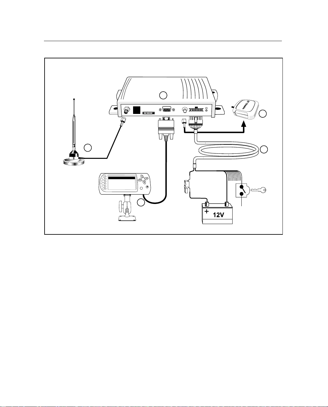
Figure 1.1 illustrates the CrossCheck GPRS 1900 Mobile Unit and
accessories.
1. CrossCheck GPRS 1900 Mobile Unit
2. EchoLDX Message Terminal Kit including:
–EchoLDX Terminal
–EchoLDX Power/Data cable
– Pedestal Mounting Kit
–EchoLDX Quick Reference Guide
3. Power and discrete I/O cable
4. GPS antenna with cable and SMA-p connector
5. GPRS antenna with cable and TNC-p connector
CrossChec k GP RS 19 00 I ns tallation Manual 5
Page 20
1 Overview
GPRS
CrossCheck GPRS
Antenna
1
5
EchoLDX
2
Figure 1.1 CrossCheck GPRS 1900 Mobile Unit and Accessories
GPS
Antenna
4
3
Ignition
Sense
6 CrossCheck GPRS 1900 Installation Manual
Page 21

1.3
CrossCheck GPRS Applications
The Trimble Mobile Solutions (TMS) Division provides you with the
core products around which you can build systems and applications
for managing your transport and logistics assets.
TMS products and services address the need for an end-to-end
solution. They provide the building blocks at both ends of the asset
management system including the on-board units mounted in the
vehicle and the Trimble Web-based gateway for dispatch and control
applications anywhere.
The on-board components are centered on the CrossCheck GPRS
receiver. You can use the receiver as a standalone unit, or you can
interface it with externa l accessorie s and sensors to make it function as
part of an on-board system.
The optional EchoLDX Message Terminal provides a driver interface
to exchange messages or generate event reports.
The CrossCheck GPRS and applications can do the following:
• Automate vehicle status changes for dispatching applications
Overview 1
• Determine time spent and distance traveled on jobs for
accounts-payable systems
• Improve efficiency by detecting unauthorized vehicle stops or
off-route activities
• Improve cus to me r s er vic e by alerting customer-service systems
of delays
• Drive compliance by keeping a time-stamped log of activities
• Improve safety by indicating speed limit violations
• Identify unauthorized use of equipment and detect theft
CrossChec k GP RS 19 00 I ns tallation Manual 7
Page 22

1 Overview
1.4
The Global Positioning System
The Global Positioning System (GPS) is a satellite-based navigation
system operated and maintained by the U.S. Department of Defense.
GPS consists of a constellation of 24 satellites providing world-wide,
24-hour, three-dimensional (3D) coverage. Although originally
conceived for military needs, GPS has a broad array of civilian
applications including timing, surveying, fleet management, marine,
land, aviation, and vehicle navigation.
GPS is the most accurate technology available for navigation. As a
satellite-based system, GPS is immune from the limitations of landbased systems, which have limited coverage and whose accuracy
varies with geographic location and, even under ideal conditions,
cannot compare with GPS.
By computing the distance to GPS satellites orbiting the earth, a GPS
receiver can calculate an accurate position. This process is called
satellite ranging. GPS receivers can also provide precise time, speed,
and course measurements which are important for vehicle mobile
positioning and communications applications.
1.5
GPS Receiver
The Cross Check GPRS includes an advanced GPS receiver, which
provides the po sit i on, course, speed and time infor m at ion requ ired for
AVL and fleet management applications. A brief overview of the GPS
receiver’s architecture a nd ope rat ion is provided in the next paragraph.
The CrossCheck GPRS’s GPS receiver features an eight-channel
digital signal processor (DSP) which operates at the GPS L1
frequency ( 1575.42 MHz) a nd processes the Coarse /Acquisition ( C/A)
code portion of the GPS signal. The RF and digital signal-processing
components of the GPS module are custom integrated circuits
designed by Trimble.
8 CrossCheck GPRS 1900 Installation Manual
Page 23

CHAPTER
2
Installation
!
Introduction
!
Installing the CrossCheck GPRS Mobile Unit
!
CrossCheck GPRS Connections
!
Inspecting and Unpacking the Shipment
!
Installer-Supplied Parts
!
Mounting the CrossCheck GPRS
!
Choosing the GPS Antenna Mounting Location
!
Routing the GPS Antenna Cable
!
Choosing a GPRS Cellular Antenna Mounting Location
!
CrossCheck GPRS Power
!
Installing the EchoLDX Kit
2
Page 24

2 Installation
2.1
Introduction
This chapter presen ts instru ctions fo r install ing the Cros sCheck GPRS
1900 Mobile Unit in a vehicle.
C
2.2
Installing the CrossCheck GPRS Mobile Unit
Warning – The CrossCheck GPRS and its antennas and accessories
should only be professionally installed by Trimble Authorized dealers.
Warning – For 1900 MHz PCS:
A minimum separation distance of 20 cm m ust be maintained between the
antenna and the person for this device to satisfy the RF exposure
requirements of the FCC. For fixed mount operation, the antenna
co-location requirements of Section 1.1307 (b) (3) of the FCC
rules must be satisfied. The maximum antenna gain, including any cable
loss, must not exceed 3dBi.
Warning – Portable operation of this unit is not permitted.
The CrossCheck GPRS 1900 Mobile Unit can be installed before or
after configuring its firmware. For example, you might want to
configure all of the units for a fleet of vehicles prior to installation.
Note – If you plan to install the CrossCheck GPRS receiver before
installing the EchoLDX Message Terminal, be sure to leave adequate
clearance to the Mobile Data Terminal port and other connectors.
Adequate cleara nce must e xi st to co nnect th e Messa g e Terminal to the
unit, and you must be able to read the LED indicators if
troubleshooting is required.
10 CrossCheck GPRS 1900 Installation Manual
Page 25
2.3
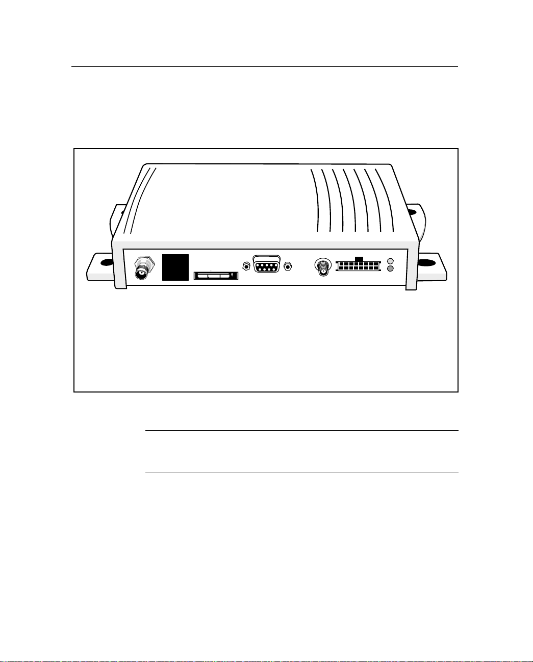
CrossCheck GPRS Connections
This section descri bes the Cr ossCheck GPRS component connections.
Figure 2.1 shows the CrossCheck GPRS connections.
2
1
1. GPRS cellular antenna connector (TNC receptacle)
2. SIM Slot
3. Message Terminal port (DB9 receptacle)
4. GPS antenna connector (SMA receptacle)
5. Power and discrete I/O
3
Installation 2
4
5
Figure 2.1 CrossCheck GPRS Connections
C
2.3.1
Warning – The SIM card provided with the CrossCheck GPRS must not
be removed. It has been locked to work only with this device and cannot
be used with any other GPRS phone.
GPRS Antenna
The CrossCheck GPRS 1900 uses a TNC receptacl e connector for the
GPRS antenna. For more information, see Appendix A.
CrossCheck GPRS 1900 Installation Manual 11
Page 26

2 Installation
2.3.2
Power and Discrete I/O Pinout
Table 2.1 lists the pinout for the power and discrete I/O signals.
Table 2.1 Power and I/O Pinout
Pin Signal Function
1V
2 GND Battery Ground
3 CHAS Chassis Ground
4 GND Ground
5 IGN Input: Ignition Sense
6 IP3 Discrete Input 3
7 IP2 Discrete Input 2
8 XP2 Discrete Output 2
9 IP1 Discrete Input 1
10 XP1 Discrete Output 1
11 IPO Discrete Input 0
12 XPO Discrete Output 0
13 Pulse 0 Pulse Input 0
14 Pulse 1 Pulse Input 1
batt
Input: Power 9-32V
15 Pulse 2 Pulse Input 2
16 12 V AUX 12 VDC Auxiliary output
12 CrossCheck GPRS 1900 Installation Manual
Page 27
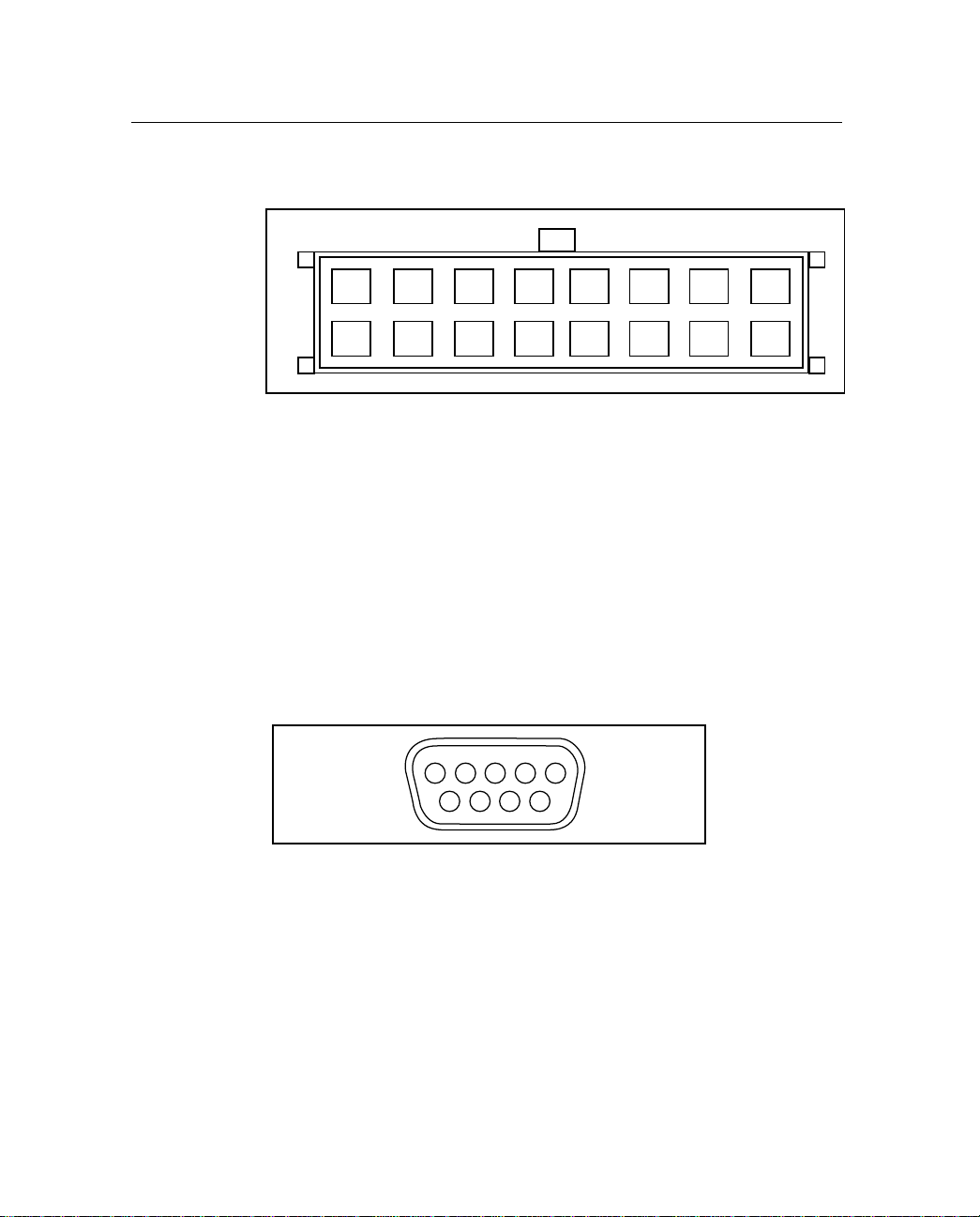
Figure 2.2 illustrates the power and discrete I/O pinout.
Installation 2
2.3.3
2.3.4
16
15
Figure 2.2 Power and Discrete I/O Pinout
14
13
12108642
1197531
GPS Antenna
The GPS antenna uses an SMA receptacle (SMA-r) connector. For
more information, see Appendix A.
Message Terminal Port
Figure 2.3 illustrates the Message Terminal port pin configuration, a
standard 9-pin DCE configuration.
12345
6789
Figure 2.3 Message Terminal Pinout
CrossCheck GPRS 1900 Installation Manual 13
Page 28

2 Installation
Table 2.2 lists the Message Terminal connector pinout.
Table 2.2 Message Terminal Connector Pinout
Pin Signal Connection
1 DCD Output: Carrier Detect
2 RxD Output: Serial Data
3 TxD Input: Serial Data
4 DTR Input: Data Terminal Ready
5 GND Ground
6 DSR Output: Data Set Ready
7 RTS Input: Request to Send
8 CTS Output: Clear to Send
9 PWR Output: 12 VDC @ 200 mA max.
(Interpreted as RS-232 high-level.)
2.4
Inspecting and Unpacking the Shipment
The CrossCheck GPRS may be shipped in one or more cartons,
depending on the number of units and the options ordered with the
shipment. Before opening the shipping containers, inspect the cartons
for punctures or damage and immediately report any damage to the
shipping carrier. Then open the shipping cartons individually and
check their contents against the packing slip.
14 CrossCheck GPRS 1900 Installation Manual
Page 29

Installation 2
Table 2.3 identifies the CrossCheck GPRS part numbers and the
included components.
Table 2.3 CrossCheck GPRS Units and Bundles
Part Number Description
46728-01 CrossCheck GPRS 1900 Mobile Unit Demo Kit (includes
GPS magnetic mount antenna, GPRS mag ne t ic mount
antenna, power and I/O cable with cigarette lighter adapter,
and EchoLDX Message Terminal Kit)
46728-11 CrossCheck GPRS 1900 Mobile Unit Kit (does not include
Power and I/O cable—must be ordered separately as
P/N 46598—or GPS and GPRS antennas)
46728-12 CrossCheck GPRS 1900 Ready Mix Mobile Unit Kit
(does not include Power and I/O Cable—must be ordered
separately as P/N 46598—or GPS and GPRS antennas)
46728-13 CrossCheck GPRS 1900 Heavy Vehicle Mobile Unit Kit
(does not include Power and I/O Cable—must be ordered
separately as P/N 46598—or GPS and GPRS antennas)
Additional cartons may be included in the shipment for GPS and
cellular antennas interface cables, and EchoLDX Kit op t ions. For a
complete listing of CrossCheck GPRS and component part numbers,
see Appendix A, Table A.19.
2.5
Installer-Supplied Parts
The installer must supply the following parts:
• Mounting fasteners for the CrossCheck GPRS
• Fasteners for mountin g the GPS or GPRS ant enna if th e antenna
is the bulkhead type
• Cable ties for securing cables to the vehicle
• GPS antenna (supplied only with the CrossCheck GPRS Demo
Kit P/N 46728-11 but also available as separate accessory item)
• GPRS Cellular antenna (supplied only with the CrossCheck
GPRS Demo Kit P/N 46728-11, but also available as separate
accessory item)
CrossCheck GPRS 1900 Installation Manual 15
Page 30

2 Installation
2.6
Mounting the CrossCheck GPRS
The CrossCheck GPRS can be installed inside almost any type of
vehicle and in any orientation. It can be installed in an enclosed
compartment or in a location with limited accessibility, as long as the
environmental specifications are maintained to ensure reliable
operation. For e xample, the CrossC heck GPRS can be installed on the
floor under a seat, or on a wall behind a seat.
Note – The CrossCheck GPRS cannot be installed inside the engine
compartment, wheel well, chassis, or on any exterior surface of the
vehicle.
Choose a loc ation for the CrossCheck GPRS that al lows for
conv enient routing and co nnection of the antenna and i nterf ace cables ,
and that has access to a power source. When selecting a mounting
location, consider the specifications listed in Appendix A, and avoid
the following hazards:
• Direct exposure to weather
• Excessive heat (exhaust manifolds)
• Excessive cold (refrigeration units)
• High-vibration areas (engine compartment, transmission)
• Corrosive fluids and gases (acids, petroleum products)
• Direct expo sure to water
(The CrossCheck GPRS is not waterproof.)
• Areas where excessive dust will be present
To mount the CrossCheck GPRS:
1. Choose the mounting location.
The CrossCheck GPRS can be mounted horizontally, vertically,
or in any convenient orientation. During normal system
operation, you do not need to see the CrossCheck GPRS LED
indicator s. However, the ability to see the LED indicators is a
definite advantage when troubleshooting the unit.
16 CrossCheck GPRS 1900 Installation Manual
Page 31

Installation 2
The integral mounting flang e is desi gned to secure the
CrossCheck GPRS to a flat surface. The flange has four holes
for securing the unit with fasteners.
2. Use self-tapping screws or machine screws to secure the unit to
the mounting surface.
I
Caution – Over-stressing the plastic mounting surface when
tightening the mounting screws can crack the plastic. Use washers
sized small enough that they do not tighten down on the plastic cover
of the CrossCheck GPRS when the mounting screws are secured.
Tightening screws without using washers can lead to compressing,
cracking, or deforming the mounting surface.
Figure 2.4 shows the mounting dimensions.
205.5 mm
(8 in)
4.8
mm
(0.18 in)
69.9 mm
(2.75 in)
Figure 2.4 CrossCheck GPRS Mounting Dimensions
CrossCheck GPRS 1900 Installation Manual 17
Page 32

2 Installation
The installer must provide an appropriate selection of fasteners to
secure the CrossCheck GP RS to the mounting surface.
• When using self-tapping screws:
– Select an appropriate size and length for the mounting
surface.
– The hole size leaves some allowance for holes drilled
slightly off center from the specified dimensions.
• When using machine screws:
– Trimble recommends the use of number m3.5
(or number 6) pan-head machine screws.
– Select a screw length, which extends a safe distance
beyond the mounting surface.
– Secure the screw with a washer and nut. Lock washers are
recommended to prevent vehicle vibration from loosening
the fasteners.
2.6.1
Connecting CrossCheck GPRS to the Vehicle Chassis
For proper operation, the aluminum chassis of the CrossCheck GPRS
must be connected elec tric ally ( grounde d) to t he ch assis of the v eh icle
on which it installed. This can be accomplished in two ways:
• Direct connection through metal screws (preferred)
• Connection through the chassis ground wire
18 CrossCheck GPRS 1900 Installation Manual
Page 33

Installation 2
Direct Connection through Mounting Screws
T o mount the CrossCheck GPRS 1900 Mobile Unit on a metal surface
that is permanently attached to the vehicle chassis (f or example, the
base of the trunk, or a mounting plate that is permanently attached to
the chassis using metal screws):
1. Fasten down the CrossCheck GPRS using metal screws driven
through the metal tabs on the sides of the unit.
2. Use star washers to ensure a reliable electrical contact to the
metal tabs.
3. Make sure the screws are tight, and that they make conta ct bo th
with the met al on the CrossCheck GPRS and with the vehicle
chassis.
Note – If this direct connection through mounting screws method is
used for chassis connection, then the chassis ground (pin 3 on the
power and discr ete I/O c onnector) on the CrossCheck GPRS should be
left unconnected.
Connection through the Chassis Gr ound Wire
If the CrossCheck GPRS cannot be mounted directly on a metal
surface that is atta ched t o the v eh icle, then us e the chass is gr ound wi re
(pin 3 on the power and discrete I/O connector) to make electrical
contact to the vehicle chassis:
1. Use a wire with gauge of at least 20 AWG to connect the
CrossCheck GPRS power connector to the vehicle chassis.
2. Use a me tal screw with a star washer to ensure a reliable
electrical contact to the vehicle chassis.
3. Keep the wire length as short as possible by selecting a
connection point in the vehicle chassis that is close to the
CrossCheck GPRS.
CrossCheck GPRS 1900 Installation Manual 19
Page 34

2 Installation
2.7
Choosing the GPS Ant enna Mounting Location
Antenna location is critical for optimum GPS performance. When
choosing a location for the GPS antenna, consider these guidelines:
• The antenna has an unobstructed view of the sky.
• The antenna is safe from damage during normal vehicle
operation and maintenance.
• The antenna is not shielded from satellite signals by metal
objects or other impenetrable materials.
GPS signals can penetrate plastic, glass and tinted glass (except
metallized glass), fiberglass, and plexiglass materials as long as the
surface is re lati v ely dr y. GPS satellite signals do no t penetr ate metal o r
dense wood.
Since GPS satellite signals can penetrate plastic, fiberglass, and glass,
the GPS antenna can also be installed on a dashboard under a sloped
windshield (if the windshield is not metallized) or under a plastic
fender or bumpe r. These alt ernative locations are likely to offer less
satellite co verage , since the met al components of the vehic le shield the
antenna from portions of the sky.
For optimum performance, the GPS antenna should be mounted on a
metal groundplane of at least 7.5 cm square (3 in. x 3 in.).
I
20 CrossCheck GPRS 1900 Installation Manual
Caution – Do not mount the GPS antenna under a metallized glass
windshield, such as those used in some vehicles for window defogging or de-icing systems. However, the GPS antenna can be
mounted under a tinted-glass windshield.
Disclaimer - The instructions included in this section apply to the
GPS antennas sold by Trimble and may not apply to third-party
products. There are many other GPS antennas available on the
market which may or may not be compatible with the
CrossCheck GPRS, including combined GPS/GSM cellular antenna
solutions which have not been tested or certified by Trimble.
Page 35

Installation 2
Additional guidelines to follow include:
• Mount the antenna in a horizontal position facing the sky, as
shown in Figure 2.5.
If the antenna must be located in the vicinity of other antennas
(radio, cellular phone), locate the GPS antenna at least 46 cm
(approximately 18 in.) away.
• Avoid areas of high vibration (for example, engine hoods).
For permanent installations, choose a location with access both
above and below the antenna-mounting surface. This access is
required for installing fasteners and for routing the antenna
cable.
Note – The standard length of magnetic-mount and bulkheadmount GPS antenna cables supplied by Trimble is 5 m
(approximately 16 ft.). Longer bulkhead-mount antenna cables
can be prepared by the installer using the guidelines presented
in Appendix A.
CrossCheck GPRS 1900 Installation Manual 21
Page 36

2 Installation
Figure 2.5 shows typical antenna-mounting locations for an
automobile.
Best Performance
Figure 2.5 Antenna Mounting Locations for Automobile
Reduced Performance
22 CrossCheck GPRS 1900 Installation Manual
Page 37

Installation 2
Figure 2.6 shows the typical antenna mounting locations for a van.
1
Best Performance the GPS antenna
should be mounted in a location with
a clear unobstructed view of the sky
1
3
Figure 2.6 Antenna Mounting Locations for Van
2
Reduced Performance - avoid locations
where the antenna does not have a
clear unobstructed view of the sky
3
Unacceptable Locations
.
2
CrossCheck GPRS 1900 Installation Manual 23
Page 38

2 Installation
The antenna can be mounted under a f iber gl ass wind defle ctor suc h as
those used on conventional and cab-over trucks as shown in
Figure 2.7. Make sure the win d de flector is not pain ted with a metalli c
finish.
Note: Must be
fiberglass
Figure 2.7 Antenna Mounted under Fiberglass Canopy
Note – The GPS antenna may be subject to performance degradation
when covered by a heavy layer of snow or ice. If these are typical
conditions for your application, mount the antenna in an accessible
location so snow can be easily removed.
The CrossCheck GPRS can receive GPS signals from one of tw o types
of optional Miniature Bulkhead GPS antennas, or a Miniature
Magnetic GPS antenna, all available from Trimble. Follow the
applicable procedure (below) to mount the GPS antenna.
24 CrossCheck GPRS 1900 Installation Manual
Page 39

Installation 2
2.7.1
Miniature BulkHead GPS Antenna with Flange
(P/N 31192-00)
Two cables are available for the Miniature Bulkhead Antenna with
Flange:
• A straight TNC-Plug-to-SMA-Plug antenna cable (P/N 36107)
• A right-angle TNC-Plug-to-straight SMA-Plug antenna cable
(P/N 36106)
For more information, see Appendix A.
Figure 2.8 shows the Miniature Bulkhead GPS antenna mounting.
Mounting Lug
Gasket
Cable
Figure 2.8 Miniature Bulkhead GPS antenna with Flange
CrossCheck GPRS 1900 Installation Manual 25
Mounting hardware.
Only two of four sets
shown for clarity.
Page 40

2 Installation
To mount the Miniature Bulkhead GPS antenna with Flange:
1. Drill holes in the mounting surface using the antenna mounting
template shown in Figure 2.9.
19 mm
(3/4 in)
7.6 cm
(3 in)
3.8 mm
(5/32 in)
Figure 2.9 Mounting Hole Dimensions
2. Slip the antenna thro ugh the la r ge r hole i n the cent er of t he hole
pattern and rotate the ant enna unt il the four hol es in t he an tenna
mounting flange are aligned to the hole circle.
3. Secure the antenna with the four screws, lock washers, and nuts.
4. Connect the TNC connector on the antenna cable to the TNC
connector on the antenna.
5. Route the cable to the CrossCheck GPRS mounting location.
Use cable ties to secure the cable along the routing path.
For detailed cable routing guidelines, see Routing the GPS Antenna
Cable on page 30.
26 CrossCheck GPRS 1900 Installation Manual
Page 41

Installation 2
2.7.2
Miniature Bulkhead GPS Antenna without Flange
(P/N 32434)
Two cables are available for the Miniature Bulkhead Antenna
without Flange:
• A straight TNC-Plug-to-SMA-Plug antenna cable (P/N 36107)
• A right-angle TNC-Plug-to-straight-SMA-Plug antenna cable
(P/N 36106)
Check the metal thickness at the mounting locatio n bef o re dri ll ing the
mounting hole. The bulkhead mount on the antenna is designed to
attach to metal surfaces with a thickness of 4.8 mm (0.1875 in.) or
less.
Figure 2.10 illustrates the antenna without the flange. For more
information, see Appendix A.
Gasket
Sheet Metal
Metal Washer
Mounting Nut
Jam Nut
Figure 2.10 Miniature Bulkhead GPS Antenna without Flange
CrossCheck GPRS 1900 Installation Manual 27
Page 42

2 Installation
To mount the antenna:
1. Choose the antenna mounting location (see Choosing the GPS
Antenna Mounting Location on page 20).
2. Drill a 3/4 inch hole at the mounting location.
3. Remove the large nut from the bottom of the antenna.
4. Mount the gasket as shown in Figure 2.10.
5. Slip the antenna through the mounting hole, and secure it with
the large nut.
6. Connect the antenna cable as shown in Figure 2.10.
7. Route the cable to the CrossCheck GPRS mounting location.
8. Connect the cable to the GPS antenna connector.
For detailed cable routing guidelines, see Routing the GPS Antenna
Cable on page 30.
2.7.3
I
28 CrossCheck GPRS 1900 Installation Manual
Miniature Magnetic GPS Antenna (P/N 37167)
The Miniature Magnetic Antenna features a magnetic mount for
attaching the unit to ferrous metal surfaces and an integral 5m cable
with SMA connector.
Caution – The magnetic-mount antenna cable has no strain relief at
the antenna end of the cable and is not recommended for permanent
installations.
Page 43

Installation 2
Figure 2.11 illustrates the miniature antenna.
Figure 2.11 Miniature Magnetic GPS Antenna
To mount the Magnetic GPS Antenna:
1. Choose the antenna mounting location (see Choosing the GPS
Antenna Mounting Location on page 20).
2. Mount the antenna to a ferrous surface.
I
3. Route the antenna cable.
The antenna features a perma nent a ntenna c able whi ch mu st be r outed
to the location where the CrossCheck GPRS is mounted.
Caution – The magnetic-mount antenna cable is exposed to the
environment. Wind could cause damage to the cable; use tie wraps to
secure the cable along its route.
See Routing the GPS Antenna Cable in the next section.
CrossCheck GPRS 1900 Installation Manual 29
Page 44

2 Installation
2.8
Routing the GPS Antenna Cable
The Magnetic GPS Antenna has an integral antenna cable, and the
Miniature Bulkhead GPS Antennas have separate cables.
If you are using one of the Miniature Bulkhead GPS Antennas, attach
the antenna cable to the connector on the base of the antenna prior to
routing the cable. When routing the cable, start at the antenna and
choose the most direct path to the Cros sChec k GPRS whil e obse rv ing
the following guidelines:
• Make sure that at least 5.1 cm (2 in.) of clearance exists
between the CrossCheck GPRS's antenna connector and the
nearest ob stacle.
• Make all cable bends, especially the bend at the SMA strain
relief to the antenna connector, with at least 1.3 cm (1 in.) bend
radius.
• Provide an adequ ate servi ce loop when routing t he cable a round
vehicle hinges to ensure that the cable is not pinched when a
hinged door opens or closes.
• Make sure that the coa x cab le is not routed through areas whe re
vehicle movement can abrade the cable surface.
• Never coil the excess antenna cable, particularly the Magnetic
GPS antenna cable. A coiled cable can act as an antenna and
cause inte rference problems.
• Protect cables from exposure to corrosive fluids.
Once the cable is routed and secured, attach the cable to the
CrossCheck GPRS GPS (SMA) connector.
30 CrossCheck GPRS 1900 Installation Manual
Page 45

2.9
Choosing a GPRS Cellular Antenna
Mounting Location
Installation 2
C
Warning – The CrossCheck GPRS and its antennas and accessories
should only be professionally installed by Trimble Authorized dealers.
Warning – For 1900 MHz PCS:
A minimum separation distance of 20 cm m ust be maintained between the
antenna and the person for this device to satisfy the RF exposure
requirements of the FCC. For fixed-mount operation, the antenna
co-location requirements of Section 1.1307 (b) (3) of the FCC
rules must be satisfied. The maximum antenna gain, including any cable
loss, must not exceed 3dBi.
Warning – Portable operation of this unit is not permitted.
Disclaimer - The instructions included in this section apply to the
cellular antennas sold by Trimble and may not apply to third-party
products. There are many other cellular antennas available on the
market which may or may not be compatible with the
CrossCheck GPRS, including combined GPS/Cellular antenna
solutions which have not been tested or certified by Trimble.
Mount the cellular whip antenna in a vertical orientation in a location
where it is safe from damage during normal vehicle operation and
maintenance. Automated vehicle washes may damage misplaced
cellular antennas.
CrossCheck GPRS 1900 Installation Manual 31
Page 46

2 Installation
Maintain a separation of at least 46 cm (or approximately 18 in.)
between the cellular (or other) and GPS antennas (as illustrated in
Figure 2.12).
46cm
GPS
Antenna
(18 in)
minimum
Cellular
Antenna
Figure 2.12 Distance Between Antenna Locations
In general, the greater the separation, the less chance of interference.
For permanent antenna installations, choose a location with access
both above and below the antenna mounting surface. This access is
required for installing fasteners and for routing the antenna cable.
Cellular phone dealers and installers are experts on cellular antenna
placement. For some installations, the installer may substitute a glassmount antenna for the antenna supplied by Trimble. Other antennas
are acceptable as long as they conform to the requirements listed in
Appendix A.
Trimble offers three cellular antenna options for the
CrossCheck GPRS. The Magnetic Mount Cellular Antenna is
recommended for temporary installati ons. A Bulkhead Mount Cellular
Antenna is recommended for permanent installat ions. A Glass Mount
Cellular Antenna is also recommended for permanent inst allati ons.
32 CrossCheck GPRS 1900 Installation Manual
Page 47

Installation 2
2.9.1
Magnetic Mount 850/1900 Cellular Antenna (P/N 46764)
The Magnetic Mount 850/1900 Cellular antenna and Magnetic Base
(see Figure 2.13) is designed for temporary mounting on any ferrous
surface.
Magnetic Mount 850/1900
Cellular Antenna
Magnetic Base
Figure 2.13 Magnetic Mount 850/1900 Cellular Antenna
The antenna features a 3.6 m (12 ft.) integral coaxial cable termina te d
with a TNC-P connector, which is compatible with the
CrossCheck GPRS’s Cellular Antenna connector. The antenna’s
magnetic base adher es to a n y fe rrous surf ace and req uires no f as tener s
or mounting hardware.
CrossCheck GPRS 1900 Installation Manual 33
Page 48

2 Installation
To mount the Magnetic-Mount 850/1900 Cellular Antenna:
1. Select an appropriate location to mount the antenna.
The center of the vehicle’s roof is the best location.
2. Thoroughly clean and remove all dust and gritty material from
the surface where the mount is to be placed (each time it is
installed).
3. Using the antenna base as a handle, place the edge of the mount
on the clean surface area. Slowly lower the mount towards the
surface until it snaps into place.
4. Route the antenna cable. For detailed cable routing guidelines,
see Routing the Cellular Antenna Cable on page 44.
I
Caution – Do not slide the mount once it is in place—this can scratch the paint surface.
Note – To avoid a reduction in holding power, do not use the mount
should on vinyl surfaces—some loss in electrical capacitance will
occur, which may interfere with operation of the antenna.
34 CrossCheck GPRS 1900 Installation Manual
Page 49

Installation 2
2.9.2
Bulkhead Mount 850/1900 Cellular Antenna (P/N 47771)
The Bulkhead Mount 850/1900 Cellular antenna is designed to be
permanently mounted on the vehicle.
Bulkhead Mount
Cellular Antenna
Figure 2.14 Bulkhead Mount 850/1900 Cellular Antenna
CrossCheck GPRS 1900 Installation Manual 35
Page 50

2 Installation
To install the antenna:
1. Drill a 19 mm (3/4 in.) hole through the vehicle’s metal surface.
2. Carefully remove burrs from t he underside of the hole and
remove p aint in a na rro w ring aro und the ho le (see Fig ure 2.15).
Use a deburring tool to remove all
burrs from the interior and exterior
of hole.
Assure that the o-ring seating
surface is free of scratches.
Figure 2.15 Burr Removal and O-Ring Seal Surface Inspection
Note – Use care to avoid scratching the top surface of the hole. The
o-ring on the cable mounting assembly must seal to the top surface of
the vehicle’s sheet metal. Scratches may prevent the o-ring from
sealing properly and could result in water leakage.
3. Screw the locking nut onto the mounting assembly and twist
one-and-a half times.
36 CrossCheck GPRS 1900 Installation Manual
Page 51

4. Feed the coax and serrated part of the mount (mounting
assembly) through the hole (Step 1, Figure 2.16).
1
Figure 2.16 Mounting the Antenna Cable Assembly
5. Pull up on the locking nut and slip the mount step into proper
alignment in the hole (Step 2, Figure 2.16).
6. Re-install the brass nut from the exterior of the vehicle
(Figure 2.17).
Installation 2
2
3
Figure 2.17 Re-installing the Brass Nut
4
CrossCheck GPRS 1900 Installation Manual 37
Page 52

2 Installation
a. Turn the brass nut until the cable mounting assembly is
secured in place. The brass nut must make metal-to-metal
contact with the vehi cle' s sheet meta l to allo w the o-ring t o
seal properly.
b. Use a spanner wrench or long-nose pliers to hold the
mounting assembly. Then use an adjustable or open-end
wrench on the locking nut and tighten firmly.
7. Place the rubber gasket over t he b ras s nut (Step 5, Figure 2.18).
5
Figure 2.18 Attaching the Antenna to the Cable Assembly
8. Carefully thread the antenna mount onto the brass nut
protruding through the top of the sheet metal. Continue to turn
the antenna mount until the rubber gasket firmly seats against
the vehicle's sheet metal surface.
38 CrossCheck GPRS 1900 Installation Manual
6
Page 53

Figure 2.19 shows the antenna before and after assembly.
Installation 2
Figure 2.19 Attaching the Bulkhead Mount 850/1900 Ce llu la r Antenna
9. Route the antenna cable to CrossCheck GPRS using the
guidelines provided in Routing the Cellular Antenna Cable on
page 44.
10. Cut the antenna cable to remove any extra slack, and install the
TNC connector on the cable end, following the manufacturer’s
recommendations.
CrossCheck GPRS 1900 Installation Manual 39
Page 54

2 Installation
2.9.3
Glass Mount 850/1900 Cellular Antenna (P/N 47773)
The Glass Mount 850/1900 Cellular Antenna is designed for
permanent installations mounted on the vehicle’s window.
Figure 2.20 Glass Mount 850/1900 Cellular Antenna
40 CrossCheck GPRS 1900 Installation Manual
Page 55

To install the antenna:
1. Select an appropriate location to mount the antenna.
Corners of the rear window or a side window are often best.
Installation 2
I
C
Warning – Do not mount the antenna where it can obstruct the driver’s
visibility.
Caution – Avoid installing the antenna:
- on curved glass.
- on glass with metallic content (that is, passivated glass:
“solar coat” or “solar cool”). Check with auto manufacturer.
- on any dark tinted area, or an area where aftermarket
tinting film has been applied.
- over in-glass AM/FM dipole antenna.
2. Clean both inside and outside mounting areas with enclosed
alcohol pad. Wipe off excess alcohol (do not allow alcohol to
dry on the glass). If there i s an obvious film on the window, use
a mildly abrasive detergent to clean.
Note – To install the antenna over defroster wires, the wires must be
placed at least one inch or more apart. Center the antenna over one
wire, allowing it to pass between the horizontal coupling plate (see
Figure 2.21).
CrossCheck GPRS 1900 Installation Manual 41
Page 56

2 Installation
Figure 2.21 Underside of Glass Antenna
3. Prepare outside mounting area by swabbing enclosed liquid
adhesion “enhancer”. Allow enhancer to dry completely before
applying outside coupler.
4. Peel the protective liner from the adhesive tape on the outside
coupler. With index arrow pointing up, mount the outside
coupler starting at the top and rolling downward. From the
inside of the window, check that the adhesive is making contact
with edges and corners. Press firmly on a ll corners and in the
center to en sure maximu m contact. If the adhesive is not
making contact, apply additional pressure where needed. The
seal can be enhanced with a drop of clear silicone sealant.
5. Remove the prot ecti ve liner from the adhesi ve ta pe on the inside
coupler. With the index arrow pointing up, mount the inside
coupler opposite the outside coupler (using the technique
described above).
6. Route the antenna cable to the CrossCheck GPRS using the
guidelines provided in Routing the Cellular Antenna Cable on
page 44.
42 CrossCheck GPRS 1900 Installation Manual
Page 57

Installation 2
7. Position the swing arm and whip to the vertical position and
tighten cap bolt at swing arm/coupler connection.
I
Caution – After installation, do not install whip or expose to water for 24-72 hours.
CrossCheck GPRS 1900 Installation Manual 43
Page 58

2 Installation
2.9.4
Routing the Cellular Antenna Cable
The Magnetic Cellular antenna has a 3.65 m (12 ft.) integral antenna
cable with a TNC-plug (TNC-p) connector. The Bulkhead Cellular
antenna has a 5.1 m (17 ft.) integral cable and the Glass Mount
Cellular antenna has a 4.5 m (15 ft.) integral cable; both cables are
terminated without a connector.
After routing the Bulkhe ad Cell ula r or Gla ss Cell ular ca ble, it must be
fitted with a TNC-p connector before attaching the cable to the
CrossCheck GPRS. Instructions for installing the TNC-p connector
are included with the antenna kit.
The next step in the installation process is routing and connecting the
antenna cable to the CrossCheck GPRS. When routing the cable, start
at the antenna and choose the most direct path to the
CrossCheck GPRS while avoiding the following hazards:
• Excess coils in the antenna cable, particularly the cellular
antenna cable. A coiled cable can act as an antenna and may
receive interference.
• Pinching the cable in a hinged door. Provide an adequate s ervice
loop when routing the cable around vehicle hinges.
• Vehicle movement that might cause cable damage. Make sure
that the coax cable is not routed through areas where vehicle
movement can abrade the cable surface.
• Exposure to environmental damage. If your cellular antenna
cable is exposed to the environment, use tie wraps to secure the
cellular antenna cable along its route to prevent wind damage.
44 CrossCheck GPRS 1900 Installation Manual
Page 59

Installation 2
2.9.5
2.9.6
Connecting the Magnetic Cellular Antenna Cable
After routing the Magnetic Cellular Antenna cable, connect the cable
to the TNC connector on the front panel of the CrossCheck GPRS.
Tighten the connector firmly to prevent loosening caused by normal
vehicle vibration.
Connecting the Permanent or Glass-Mount Cellular Cable
Once the cable routing is complete and the cable is secured attach the
TNC connector on the ante nna cable. Then atta ch the cable to the TNC
connector on the front panel of the CrossCheckGPRS.
CrossCheck GPRS 1900 Installation Manual 45
Page 60

2 Installation
2.9.7
Connecting the Power and I/O Cable
Use the flexib le po wer and I/O cable (PN 46598) to conn ect po wer and
a variety of input and output peripherals to the CrossCheck GPRS as
shown in Figure 2.22.
2
4
8
10 12
14 16
15
13
11
9
Connector
Molex Micro-Fit 3.0 16-Pin
Molex P/N 43025-1600
Molex Female
templated Contact
Molex P/N 43030-0001
Batt.GND
Black
Yellow/Blue
Yellow
Gray
GND
Input 1
Discrete Output 1
Pins
2A @ 250V
V
batt
Blade T ype
Batt. GND
Chassis GND
GND
IGN
IP3
IP2
XP2
IP1
XP1
IP0
XP0
Pulse 0
Pulse 1
Pulse 2
12V Aux
6
57
3
1
Front View
Side View
V
1 Red Input Power 9-32V
batt
2 GND Black
3 GND Green Chassis GND
4 GND
5 White Ignition Sense Input
IGN
IP3
6 Input 3
IP2
7 Violet Input 2
XP2
8 Orange Discrete Output 2
IP1
9
XP1
10
IP0
11 Pink/Gray Input 0
12 Brown Discrete Output 0
XP0
13 Pulse 0 Black/Orange Pulse Counter Input 0
14 Pulse 1 Blue/Gray Pulse Counter Input 1
15 Pulse 2 Blue Pulse Counter Input 2
16 12V AUX Red/Black or 12 VDC Auxiliary Output
Black/Gray
Figure 2.22 Power and I/O Cable
The Power and I/O Cable includes 14 wires with 91 cm (3 ft.) of
length. The Input power wire (red) and the ignition sense input wire
(white) are 4.87 meters (16 ft.) long.
46 CrossCheck GPRS 1900 Installation Manual
Page 61

Installation 2
Table 2.4 provides pinout information for the Power and I/O cable.
Table 2.4 Power and I/O Cable Pinout
Pin Signal Color Termination Length (in.)
1V
2 B AT GND Black Ring Lug 36
3 CHAS GND Green Ring Lug 36
4 GND Black/White Cut Flush 36
5 IGN White Cut Flush 192
6 IP3 Yellow/Blue Cut Flush 36
7 IP2 Violet Cut Flush 36
8 XP2 Orange Cut Flush 36
9IP1 Yellow Cut Flush36
10 XP1 Gray Cut Flush 36
11 IP0 Pink/Gray Cut Flush 36
12 XP0 Brown Cut Flush 36
13 PULSE 0 Black/Orange Cut Flush 36
14 PULSE 1 Blue/Gray Cut Flush 36
15 PULSE 2 Blue Cut Flush 36
16 12V AUX Red/Black or Black/Gray Cut Flush 36
batt
Red Cut Flush 192
CrossCheck GPRS 1900 Installation Manual 47
Page 62

2 Installation
2.9.8
Inputs (IP0 to IP3)
The CrossCheck GPRS supports four discrete inputs. The circuit
diagram is shown in Figure 2.23.
3.3V
330K
Input
Figure 2.23 Input Circuit Diagram
Input Logic High: Open circuit or Vin > 2.4 VDC
Input Logic Low: V
Input Current (Max) < 1 mA at 12 VDC
3K
470pf
< 0.8 VDC
in
The inputs must remain in either state for at least
500 milliseconds before the CrossCheck GPRS
detects the input.
100K
0.01µF
To logic
Input Protection: Protected up to at least V
Each input floats to a logic-high state (inactive) when left open.
Grounding an input causes a logic-low state (active). The
CrossCheck GPRS can be configured to detect either logic-high or
logic-low states at the inputs whenever the unit is powered on.
Note – When the CrossCheck GPRS is powered off or in Power
Management mode, it can only detect a logic-low (grounded) input.
The discrete inputs ar e compat ible wi th prop er ly conne cted r elays a nd
switches or with standar d 3.3 VDC logic le v e ls . A pr operly connected
relay or switch allows the input to float high in one position and
grounds the input in the other position.
48 CrossCheck GPRS 1900 Installation Manual
continuous
batt
Page 63

Installation 2
2.9.9
Pulse Counting Inputs (Pulse 0 to Pulse 2)
The CrossCheck GPRS also supports three pulse-counting inputs that
can be used to support different sensors like a speed sensor or others
for differe nt a ppl ications. The circuit diagr am is shown in Figure 2.23.
3.3V
330K
Input
3K
470pf
Figure 2.24 Pulse Counting Input Circuit Diagram
Input Logic High: Open circuit or Vin > 2.4 VDC
Input Logic Low: V
< 0.8 VDC
in
The inputs must remain in either state for at least
500 microseconds before the CrossCheck GPRS
detects the input.
Input Current
< 1 mA at 12 V
I
in
(Max)
Minimum Pulse
500 microseconds
Width
Input Protection: Protected up to at least V
100K
0.01µF
continuous
batt
To logic
CrossCheck GPRS 1900 Installation Manual 49
Page 64

2 Installation
2.9.10
Outputs (XP0 to XP2)
The CrossCheck GPRS features three discrete outputs (XP0–XP2) for
driving external devices such as relays, alarms, and so on.
• When inactive (use state), the discrete outputs are tied to vehicle
battery voltage (nominally 12 VDC) through a 15 kOhm
resistor.
• When active, the outputs are shorted to ground through a
bipolar junction transistor. In the active (low) state, the outputs
can sink up to 200 mA.
Figure 2.25 shows a diagram of a discrete output.
Vbatt
15K
36V
0.2A
0.01µF
Output
470pf
Figure 2.25 Output Circuit Diagram
Output Inactive: 15 kOhms through V
Output Active: Tied to ground through a saturated bipolar
junction transistor, V
200 mA; V
10 mA
Output Protection: Protected against direct shorts to ground
Output Sink Current
Capability
50 CrossCheck GPRS 1900 Installation Manual
Up to 200 mA
< 0.5 VDC at
out
batt
1.5 VDC at
out
Page 65

Installation 2
Figure 2.26 shows the cable connections between the EchoLDX
Messaging Terminal and the CrossCheck GPRS.
CrossCheck GPRS
Message T erminal Port
EchoLDX
Power/Data Cable
EchoLDX
Figure 2.26 EchoLDX Message Terminal to CrossCheck GPRS Connections
CrossCheck GPRS 1900 Installation Manual 51
RJ-45 Connector
To Serial Port 2 on
EchoLDX
Page 66

2 Installation
2.10
CrossCheck GPRS Power
The CrossCheck GPRS operates on input voltages from 9–32 VDC.
The low-noise amplifier integrated on the GPS antenna draws power
from the CrossCheck GPRS through the antenna cable. The
CrossCheck GPRS does not require any special power-up or down
sequencing.
The CrossCheck GPRS’s power circuitry is designed to protect the
unit from random power fluctuations and conditions. Input circuits
protect against transient voltage spikes found in most auto and truck
environments. An external fuse protects against excessive current.
For more information on the CrossCheck GPRS power requirements,
see Appendix A.
52 CrossCheck GPRS 1900 Installation Manual
Page 67

Figure 2.27 illustrates the power and I/O cable.
2
4
8
10 12
14 16
15
13
11
9
Molex Micro-Fit 3.0 16-Pin
Molex P/N 43025-1600
Molex Female
templated Contact
Molex P/N 43030-0001
Batt.GND
Black
Yellow/Blue
Yellow
Gray
GND
Input 1
Discrete Output 1
Connector
2A @ 250V
V
batt
Blade T ype
Batt. GND
Chassis GND
GND
IGN
IP3
IP2
XP2
IP1
XP1
IP0
XP0
Pulse 0
Pulse 1
Pulse 2
12V Aux
6
57
3
1
Front View
Side View
V
1 Red Input Power 9-32V
batt
2 GND Black
3 GND Green Chassis GND
4 GND
5 White Ignition Sense Input
IGN
IP3
6 Input 3
IP2
7 Violet Input 2
XP2
8 Orange Discrete Output 2
IP1
9
XP1
10
IP0
11 Pink/Gray Input 0
12 Brown Discrete Output 0
XP0
13 Pulse 0 Black/Orange Pulse Counter Input 0
14 Pulse 1 Blue/Gray Pulse Counter Input 1
15 Pulse 2 Blue Pulse Counter Input 2
16 12V AUX Red/Black or 12 VDC Auxiliary Output
Black/Gray
Installation 2
Pins
Figure 2.27 Pow er and I/O Cable
Note – Trimble r e commend s ins tal li ng the power and groun d leads as
close to the battery as poss ible to en sure that the CrossChec k GPRS is
connected to the cleanest possible source of power.
C
Warning – The CrossChec k GPRS requires a 2A fuse to be installed in i ts
power cable (V
Power/Data cable P/N 46598. Install the fuse holder and fuse as close as
possible to the vehicle battery.
). A 2A fuse and fuse holder is supplied with the
batt
CrossCheck GPRS 1900 Installation Manual 53
Page 68

2 Installation
The CrossCheck GPRS is protected against both input power overvoltage and reverse polarity. The DC ground line connects to the
vehicle’s DC ground. The ignition-sense lead, if connec ted to a s ource
of ignition-switched battery voltage, senses when the vehicle’s
ignition is active. There are three connection options for connecting
the power, ground, and ignition-sense wires. These options are
described in the next three sections.
2.10.1
Connections For Power Management
The CrossCheck GPRS operates continuously only when the vehicle
is running. When the ignition is off, the CrossCheck GPRS goes to
sleep, drawing reduced power. For more information on current draw
in different operation modes, see Appendix A.
The default Power Management configuration for the CrossCheck
GPRS is the following:
• When the ignition is OFF, the unit goes to sleep state after
15 minutes.
• If the Echo LDX is connected to the CrossCheck, the EchoLDX
will turn off 1 minute after ignition OFF is detected.
54 CrossCheck GPRS 1900 Installation Manual
Page 69

Installation 2
Figure 2.28 illustrates the Power Management connections.
To CrossCheck
Power and I/O Cable
V
batt.
Batt. GND
Chassis GND
GND
IGN
IP3
IP2
XP2
IP1
XP1
IP0
XP0
Pulse 0
Pulse 1
Pulse 2
12V Aux
White
GPRS
Green
Black
Red
Blade T ype
2A @ 250V
Figure 2.28 Power Management Connections
To install the power cable for us e with th e Po we r Managemen t feat ure :
1. Connect the primary power line to a nonswitched/continuous
source of DC power, such as the vehicle’s battery.
2. Connect the ignition-sense line to ignition-switched battery
power so that this line is active when the ig nition is on.
CrossCheck GPRS 1900 Installation Manual 55
Page 70

2 Installation
2.10.2
I
Continuous P o w er Connection No Power Management
For the Continuous Power connection (see Figure 2.29), the
CrossCheck GPRS operates and draws power continuously, even
when the vehicle is not running:
• Idle mode (not transmitting) without the EchoLDX Message
Terminal, 15 0 mA is typical @ 12 VDC
• Idle mode (not transmitting) with the EchoLDX Message
Terminal, 22 0 mA is typical @ 12 VDC
Caution – When using the Continuous Power connection, the
CrossCheck GPRS may drain a car battery in a vehicle that is not
running in 1 to 3 weeks, depending on the battery size, quality, and
remaining life span. In the Continuous Power connection, the
CrossCheck GPRS can also drain the battery of a vehicle that is not
running long enough to compensate for the current draw of the
CrossCheck. Observe extreme care when using this connection
option. The CrossCheck GPRS will automatically power off when the
voltage drops below 9 VDC.
56 CrossCheck GPRS 1900 Installation Manual
Page 71

Figure 2.29 illustrates connections for Continuous Power.
Installation 2
To CrossCheck
Power and I/O Cable
V
batt.
Batt. GND
Chassis GND
GND
IGN
IP3
IP2
XP2
IP1
XP1
IP0
XP0
Pulse 0
Pulse 1
Pulse 2
12V Aux
White
GPRS
Green
Black
Red
2A @ 250V
Blade T ype
Figure 2.29 Continuous Power Connections
To connect the power cable to Continuous Power:
1. Connect the primary power line.
2. Connect the ignition-sense line to a nonswitched/continuous
source of DC power, such as the vehicle’s battery.
CrossCheck GPRS 1900 Installation Manual 57
Page 72

2 Installation
58 CrossCheck GPRS 1900 Installation Manual
Page 73

CHAPTER
3
Operation
In this chapter:
!
Introduction
!
LED Indicators
!
GPS Receiver Operation
3
Page 74

3 Operation
3.1
Introduction
Once you have installed and configured the CrossCheck GPRS, it is
ready for operation. When power is applied, the CrossCheck GPRS
operates automatically without user intervention, based on its
firmware configuration.
This chapter provides a ba sic overview of the CrossCheck GPRS’s
operation, including:
• LED Indicators
• GPS Receiver
• GPRS Transceiver
60 CrossCheck GPRS 1900 Installation Manual
Page 75

3.2
LED Indicators
The CrossCheck GPRS includes two LED indicators: GPS and GPRS.
The firmware continuously monitors the GPS receiver and the
CrossCheck GPRS operation.
Figure 3.1 shows the CrossCheck GPRS LED indicators.
Operation 3
GPRS LED (Amber)
GPS LED (Green)
Figure 3.1 CrossCheck GPRS LED Indicators
3.2.1
LED States
The GPS and GPRS LED have three states: On, Off, and Blink.
When both LED indicators are off, the CrossCheck GPRS’s power is
off. When one or more LED indicators are on or blinking, the power
is on.
CrossCheck GPRS 1900 Installation Manual 61
Page 76

3 Operation
3.2.2
LED Power-On Sequence
When the CrossCheck GPRS’s ignition input and power inputs are
activated:
• The LEDs blink once.
• Both turn off for approximately 5 seconds.
The GPS LED is on for approximately 2 seconds, then blinks until the
first position fix is computed. The GPRS LED blinks until the unit is
registered with a GPRS network, at which point the GPRS LED
turns on.
3.2.3
GPS and GPRS LED States
Table 3.1 identifies the GPS LED states.
Table 3.1 GPS LED States (Green LED)
GPS LED State Meaning
On Computing GPS position fixes.
Blink Not computing GPS position fixes.
Off No power is available, or the ignition is off.
Table 3.2 identifies the GPRS LED states.
Table 3.2 GPRS LED States (Amber LED)
GPRS LED State Meaning
On Data call in progress.
Slow Blink No GPRS co ve rage is av ailab le; the C rossChe ckGPRS is not registered
with network.
Off No power is available, or the ignition is off.
62 CrossCheck GPRS 1900 Installation Manual
Page 77

3.3
GPS Receiver Operation
At power-up, the GPS receiver initializes with the last-known position
if one is available. U sing this information, the G PS receiver acquires
satellite signals.
• During the satellite acquisition process—which normally
requires less than 45 seconds—the green GPS LED blinks.
• Once three or more satellites are acquired, the GPS receiver
computes positions, course, and speed, and the GPS LED
remains on.
A blinking GPS LED indicates that the GPS receiver is not tracking
enough satellites to calculate a current position. This occurs
occasionally when the vehicle is obscured from satellite signals by
terrain, buildings, trees, tunnels or other structures. During this
period—called satellite reacquisition—the GPS receiver continuously
searches for the obscured satellites and expands its search to other
satellites to continue position computations. For brief blockages, the
GPS receiver normally reacquires a lost satellite signal and resumes
position fixes in less than 2 seconds.
Operation 3
Note – If the Cr o ssCh eck GPRS unit does not have a valid last-known
position, the unit will be forced to perform a cold start which normally
requires less than 3 minutes. For example, this would happen the first
time the unit is turne d on, or if the u nit has ne ve r been on long enough
to obtain an Almanac. To obtain an Almanac, the uni t mus t t r a ck GPS
satellites for up to 30 minutes.
CrossCheck GPRS 1900 Installation Manual 63
Page 78

3 Operation
64 CrossCheck GPRS 1900 Installation Manual
Page 79

APPENDIX
A
Specifications
In this appendix:
!
Introduction
!
Standard Components
!
Environmental Specifications
!
I/O Characteristics
!
Accessories (ordered separately)
!
CrossCheck GPRS Part Numbers
A
Page 80

A Specifications
Introduction
A.1
This appendix lists the CrossCheck GPRS Mobile Unit and antenna
specifications.
Standard Components
A.2
The tables include general specifications and requirements for the
following:
• General Specifications, Table A.1
• Firmware Specifications, Table A.2
• GPS Specifications, Table A.3
• GPS Antenna Requirements, Table A.4
• GPRS Communications Specifications, Table A.5
• Cellular A ntenna Requirements, Table A .6
• CrossCheck GPRS Mobile Unit Physical Specifications,
Table A.7
• CrossCheck GPRS Mobile Unit, Table A.8
• Miniature Bulkhead GPS Antenna with Fla nge (P/N 31192-00),
Table A.9
• Miniature Bulkhead GPS Ant enna without Flang e (P/N 32434),
Table A.10
• Miniature Magnetic GPS Antenna (P/N 37167), Table A.11
• MDT Port, Table A.15
• Discrete Inputs: IP0 to IP3, Table A.16
• Pulse Counter Inputs, Table A.17
• Discrete Outputs: XP0 to XP2, Table A.18
• Component Part Numbers, Table A.19
66 CrossCheck GPRS 1900 Installation Manual
Page 81

Table A.1 General Specifications
Item Specification
Input Voltage 9.0 to 32.0 VDC
Specifications A
Current Consumption
(typical)
MDT Port (1) RS-232 DCE
Serial Port Speed (bps) 9600
Inputs & Outputs Discrete Inputs: (4) switch closures
Sensor Power Output (1) 100 mA max at 11.5 V ±1.0 VDC
Status LEDs GPS (green) and GPRS (amber)
Transmitting:
with MDT: 340 mA (1.6 A peak) at 12 VDC
without MDT: 270 mA (1.5 A peak) at 12 VDC
Not transmitting:
with MDT: 160 mA at 12 VDC
without MDT: 90 mA at 12 VDC
Sleepmode: < 10 mA at12 VDC
Ignition sense: Off: <0.8 V; On: >2.4 V
Pulse Counting Inputs: (3) minimum pulse width:
500 microseconds
Discrete Outputs: (3) 200 mA low -side drivers,
CrossCheck GPRS 1900 Installation Manual 67
Page 82

A Specifications
Table A.2 Firmware Specifications
Item Specification
Configurable Parameters
(Over the Air)
Speeding Reports Enable speed and duration thresholds
Stop Reports Enable speed and duration thresholds
Mileage/Run time Set the initial odometer value and engine run time counter
Messaging Available through Trimble’s EchoLDX Message Terminal
Table A.3 GPS Specifications
Item Specification
Receiver L1 frequency, C/A code (SPS), 8-channel continuous tracking
Update Rate Once per second maximum
Geo-fence area for Job Sites
Geo-fence area for Home Sites
Entry Speed Limit for Site Dispatch
Exit Speed Limit for Site Dispatch
Site dispatch time-out
Minimum duration time to detect entry/exit regions
Automatic status reporting for ready mix applications.
Support datalogging that allows the CrossCheck GPRS to
store messages and events for up to 1 week while out of the
network coverage.
receiver using the Trimble FirstGPS™ and Colossus™
technology
Accuracy, no S/A* Pos iti on: < 10 meters (50% CEP)
Velocity: < 0.5 meters/second
68 CrossCheck GPRS 1900 Installation Manual
Page 83

Table A.3 GPS Specifications (Continued)
First Acquisition Cold start: < 180 seconds in 90% of cases
Warm start: < 45 seconds in 90% of cases
Reacquisition after 15 seconds of blockage: < 2 seconds in
90% of cases
Datum WGS-84
Specifications A
Reacquisition after Signal
Loss
* All GPS receivers are subject to degradation of position and velocity accuracies under
Department of Defense imposed Selective Availability (S/A).
Table A.4 GPS Antenna Requirements
Item Specification
Antenna Impedance 50 Ω
Antenna RF Gain 20 dBi minimum gain, measured at the input connector to the
Noise Figure 2.5 dB maximum, measured at the input connector to the
VSWR 2:1 Max over range
Power 5.0 ±0.5 VDC @ 40 mA maximum on center conductor
Table A.5 GPRS Communications Specifications
< 2 seconds in 90% of cases
CrossCheck GPRS
CrossCheck GPRS
Item Specification
Cellular Internal GPRS module Class B
Time slots 2 Rx, 1 Tx
2W @ 900 MHz
1W @ 1900 MHz
CrossCheck GPRS 1900 Installation Manual 69
Page 84

A Specifications
Table A.5 GPRS Communications Specifications (Continued)
Frequencies Dual band 900/1900 MHz
SIM 3 VDC
Regulatory Approvals CrossCheck GPRS complies with the European
Telecommunications Standards Institute specifications
ETS 301 489-1; CE MARK; EC R& TTE Type Examination,
FCC Part 15, FCC Part 24, Low Voltage Directive (EN60950),
e-mark, PTCRB and Industry Canada requirements.
70 CrossCheck GPRS 1900 Installation Manual
Page 85

Specifications A
Table A.6 Cellular Antenna Requirements for GSM 1900 PCS
Item Specification
Antenna Type For the CrossCheck GPRS 1900: Passive, 1900 or 900/1900
MHz nominal, omnidire cti ona l
Antenna Impedance 50 Ω (nominal)
VSWR 2:1 Max over entire frequency range
Gain (including cable loss) Min 0 dBi
Max for mobile installations: 3 dBi
Max for fixed installations: 7 dBi
Frequency Tx: 1850-1910 MHz GPRS 1900
Rx: 1930-1990 MHz GPRS 1900
C
Warning – For 1900 MHz PCS:
A minimum separation distance of 20 cm m ust be maintained between the
antenna and the person for this device to satisfy the RF exposure
requirements of the FCC. For fixed mount operation, the antenna
co-location requirements of Section 1.1307 (b) (3) of the FCC
rules must be satisfied. The maximum antenna gain, including any cable
loss, must not exceed 3dBi.
Warning – Portable operation of this unit is not permitted.
CrossCheck GPRS 1900 Installation Manual 71
Page 86

A Specifications
Table A.7 CrossCheck GPRS Mobile Unit Physical Specifications
Item Specification
Assembly Bottom: Aluminum
Top: Injection-molder plastic with integrated shield
Size 228 mm W x 121 mm D x 36 mm H
(8.97 in. W x 4.76” D x 1.42 in. H)
Weight 485 g (1 lb, 1.1 oz.)
Connectors MDT: DB9 (receptacle)
Power/Ignition + Digital I/O: Molex Micro-Fit 3.0 16-pin 2-row
locking (plug)
GPS antenna: SMA (receptacle) 50 Ω
GPRS antenna: TNC (receptacle) 50 Ω
72 CrossCheck GPRS 1900 Installation Manual
Page 87

A.3
Enviro nmental Specificatio n s
The tables in this section list the environmental specifications for the
for following:
• CrossCheck GPRS Mobile Unit
• Miniature Bulkhead GPS Antenna with Flange (P/N 31192-00)
• Miniature Bulkhead GPS Antenna without Flange (P/N 32434)
• Miniature Magnetic GPS Antenna (P/N 37167)
Table A.8 CrossCheck GPRS Mobile Unit
Item Specification
Operating Temperature –20°C to +55°C (–4°F to 131°F) for 900
–10°C to +55°C (–14°F to 131°F) for 1900
Storage (non-operating)
Temperature
Humidity 5% to 95% RH, non-condensing at +40°C
Velocity 450 meters/second
Vibration 0.008g
Shock Operational: 40 g for 11 milliseconds
–40°C to +85°C (–40°F to 185°F)
2
/Hz 5 Hz
+3dB/Octave 5 Hz to 20 Hz
2
/Hz 20 Hz to 100 Hz
0.05g
–3dB/Octave 100 Hz to 800 Hz
0.001g2/Hz 800 Hz to 1000 Hz
Non operational: 75 g for 6 milliseconds
Specifications A
MTBF 100,000 hours
CrossCheck GPRS 1900 Installation Manual 73
Page 88

A Specifications
Table A.9 Miniature Bulkhead GPS Antenna with Flange (P/N 31192-00)
Item Specification
Size 62.6 mm D x 19.0 mm H (3.5 in. D x 0.75 in. H)
Weight 0.13 kg (4.59 ounces)
Mounting Hole Circle 762 mm (3.0 in.), 4 holes, 0.6 mm (0.15 in.)
Center Mounting Hole 63 mm (0.75 in.)
Threaded Nut 63 mm TNC (0.75 in.)
Operating Temperature –40°C to +85°C (–40°F to 185°F)
Storage Temperature –55°C to +85°C (–67°F to 185°F)
Humidity 5% to 95% RH, non-condensing at +40°C (104°F)
Casing Dustproof, waterproof, shock-resistant polycarbonate
Minimum Gain 28 dBi
Maximum Allowable Cable Loss 8 dB
Table A.10 Miniature Bulkhead GPS Antenna without Flange (P/N 32434)
Item Specification
Size 62.6 mm D x 19.0 mm H (3.5 in. D x 0.75 in. H)
Weight 0.13 kg (4.59 ounces)
Center Mounting Hole 63 mm (0.75 in.)
Threaded Nut 63 mm TNC (0.75 in.)
Operating Temperature –40°C to +85°C (–40°F to 185°F)
Storage Temperature –55°C to +85°C (–67°F to 185°F)
Humidity 5% to 95% RH, non-condensing at +40°C (104°F)
74 CrossCheck GPRS 1900 Installation Manual
Page 89

Specifications A
Table A.10 Miniature Bulkhead GPS Antenna without Flange (P/N 32434) (Continued)
Casing Dustproof, waterproof, shock-resistant polycarbonate
Minimum Gain 28dBi
Maximum Allowable Cable Loss 8 dB
Table A.11 Miniature Magnetic GPS Antenna (P/N 37167)
Item Specification
Size 40.0 mm W x 47.0 mm D x 13.3 mm H
(1.515 in. W x 1.85 in. D x 0.524 in. H)
Weight Antenna and cable: 0.13 kg (4.59 ounces)
Antenna only: 0.045 kg (1.59 ounces)
Operating Temperature –40°C to +85°C (–40°F to 185°F)
Storage Temperature –55°C to +85°C (–67°F to 185°F)
Humidity 5% to 95% RH
Casing Dustproof, waterproof, shock -res is tan t poly ca rbon ate with
magnetic mount
Minimum Gain 26 dBi
Table A.12 Magnetic Mount 850/1900 Cellular Antenna (P/N 46764)
Item Specification
Frequency 825-896 / 1850-1990 MHz
Gain Cellular: 3 dBd/5.2 dBi (1.5 dBd/3.7 dBi including cable loss)
PCS: 3 dBd/5.2 dBi (0.7 dBd/2.9 dBi including cable loss)
Type Cellular: Collinear
PCS: 5/8 over 5/8 over 1/2 wave
VSWR (see bandwidth) 2.0:1 or less
Power Rating 7 W
Color Black
CrossCheck GPRS 1900 Installation Manual 75
Page 90

A Specifications
Table A.12 Magnetic Mount 850/1900 Cellular Antenna (P/N 46764) (Continued)
Item Specification
Cable Type Coaxial RG-58/U Dual Shield
Cable Length 2.65 m (12 ft)
Base Size 76 mm (3 in.)
Max Height 330 mm (13 in.)
Table A.13 Bulkhead Mount 850/1900 Cellular Antenna (P/N 47771)
Item Specification
Frequency 825-896/ 1850-1990 MHz
Gain Cellular: 3 dBd/5.2 dBi (1.5 dBd/3.7 dBi including cable loss)
PCS: 3 dBd/5.2 dBi (0.7 dBd/2.9 dBi including cable loss)
Type Cellular: Collinear
PCS: 5/8 over 5/8 over 1/2 wave
VSWR (see bandwidth) 1.5:1 or less
Power Rating 100 W
Color Black
Cable Type Coaxial RG-58/U Dual shield
Cable Length 5.18 m (17 ft.)
Max Height 355 mm (14 in.) max
Mounting 19 mm (3/4 in.) roof mount
76 CrossCheck GPRS 1900 Installation Manual
Page 91

Specifications A
Table A.14 Glass Mount 850/1900 Cellular Antenna (P/N 47773)
Item Specification
Frequency 825-896/ 1850-1990 MHz
Gain Cellular: 3 dBd/5.2 dBi (1.5 dBd/3.7 dBi including cable loss)
PCS: 3 dBd/5.2 dBi (0.7 dBd/2.9 dBi including cable loss)
Type Cellular: Collinear
PCS: 5/8 over 5/8 over 1/2 wave
VSWR (see bandwidth) 2.0:1 or less
Power Rating 100 W
Color Black
Cable Type Coaxial RG-58/U Dual Shield
Cable Length 4.057 m (15 ft.)
Base Size 44.45 mm X 48.26 mm (1.75 in. X 1.9 in.)
Max Height 355.6 mm (14 in.)
A.4
I/O Characteristics
Tab le A.15 MDT Port
Item Specification
Physical DB9 - receptacle
Logical TXD, RXD, RTS, CTS, GND, DTR, DCD, DTS, 12 ±0.5 V
provided through Pin 9
Baud Rates 9600, No parity, 8 bits, 1 stop bit
CrossCheck GPRS 1900 Installation Manual 77
Page 92

A Specifications
Table A.16 Discrete Inputs: IP0 to IP3
Item Specification
Input Logic High Open circuit or V
> 2.4 VDC
in
Input Log i c Low Vin < 0.8 VDC
The inputs must remain in either state for at least
500 milliseconds before the CrossCheck GPRS detects
the input.
Input Current I
± 1 mA
in
Input Protection Protected up to at least V
Table A.17 Pulse Counte r Inputs
Item Specification
Input Logic High Open circuit or V
Input Log i c Low V
< 0.8 VDC
in
> 2.4 VDC
in
Input Current Iin ± 1 mA
Minimum Pulse Width 500 µs
Input Protection Protected up to at least V
Table A.18 Discre te Outputs: XP0 to XP2
continuous
Batt
continuous
Batt
Item Specification
Output Inactive 15 KΩ tied to V
Warning: Short circuits to V
batt
must be avoided as they can
batt
cause damage to the unit.
Output Active Tied to ground through a saturated bipolar junction
transistor, V
< 0.5 VDC @ 10 mA
V
out
< 1.5 VDC @ 200 mA;
out
Output Sink Current Capability Up to 200 mA
Output Protection Protected against shorts to ground
78 CrossCheck GPRS 1900 Installation Manual
Page 93

A.5
Accessories (ordered separately)
The following accessories can be ordered separately:
• GPS antennas: Permanent or magnetic mount
• Power and Digital I/O Cable with or without Cigarette Adapter
• Optional EchoLDX Message Terminal Kit including:
–EchoLDX Mobile Data Terminal
– Power/Data Cable
– Pedestal Mount Kit (6”)
–EchoLDX Message Terminal Installation and User’s
Manual (available online)
– Quick Re ference Guide
A.6
CrossCheck GPRS Part Numbers
Part numbers for the CrossCheck GPRS, options, and accessories are
listed in Table A.19.
Specifications A
Table A.19 Component Part Numbers
Description Part No.
CrossCheck GPRS 1900 Mobile Unit Demo Kit (includes GPS magnetic
mount antenna, GPRS magnetic mount antenna, power and I/O cable with
cigarette lighter adapter, and EchoLDX Message Terminal Kit)
CrossCheck GPRS 1900 Mobile Unit Kit (does not include Power and I/O
cable—must be ordered separately as P/N 46598—or GPS and GPRS
antennas)
CrossCheck GPR S 190 0 R ead y M ix M obi le Uni t Kit (do es not in clu de Power
and I/O Cable—must be ordered separately as P/N 46598—or GPS and
GPRS antennas)
CrossCheck GPRS 1900 Heavy Vehicle Mobile Unit Kit (does not include
Power and I/O Cable—must be ordered separately as P/N 46598—or GPS
and GPRS antennas)
CrossCheck GPRS 1900 Installation Manual 79
46728-01
46728-11
46728-12
46728-13
Page 94

A Specifications
Table A.19 Component Part Numbers (Continued)
Description Part No.
Upgrade Kits
EchoLDX Message Terminal Kit 46722-00
GPS Antenna and Cable Bundles
GPS Antenna bundle (flange, straight cable), Includes:
31192-00 Mini Bulkhead antenna, TNC-p, gasket, 5-hole flange
36107 Cable, straight, TNC-r to straight SMA-p, 5 meter
GPS Antenna bundle (flange , right-ang le ca ble), Includes:
31192-00 Mini Bulkhead antenna, TNC-p, gasket, 5-hole flange
36106 Cable, right angle, TNC-r to right angle SMA-p, 5 meter
GPS Antenna bundle (no flange, straight cable), Includes:
32434 Mini Bulkhead antenna, TNC-p, gasket, no flange
36107 Cable, straight, TNC-r to straight SMA-p, 5 meter
GPS Antenna bundle (no flange, right-angle cable), Includes:
32434 Mini Bulkhead antenna, TNC-p, gasket, no flange
36106 Cable, right angle, TNC-r to right angle SMA-p, 5 meter
GPS Antennas and Cables - separate
36697-00
36698-00
36699-00
36700-00
Mini Bulkhead antenna, TNC-p, gasket, 5-hole flange 31192-00
Mini Bulkhead antenna, TNC-p, gasket, no flange 32434
Cable, right angle, TNC-r to straight SMA-p, 5 meter 36106
Cable, straight, TNC-r to straight SMA-p, 5 meter 36107
Right angle adapter, SMA-p to SMA-r 36200
Mini Magnetic antenna with 5-meter cable, SMA-p 37167
GPRS Cellular Antennas
Magnetic Mount 850/1900 Cellular antenna 46764
Bulkhead Mount 850/1900 Cell ula r antenn a 47771
Glass Mount 850/1900 antenna 47773
Cables and Accessories
Power and I/O Cable - single 46598
80 CrossCheck GPRS 1900 Installation Manual
Page 95

Specifications A
Table A.19 Component Part Numbers (Continued)
Description Part No.
EchoLDX Power/Data Cable, 2.90 meter 46755
EchoLDX Quick Reference Guide 46845-00-ENG
Pedestal Mounting Kit (6”) 46950
Documentation (free download of latest version from the Web site)
CrossCheckGPRS 1900 Installation Manual (only in electronic PDF format) 47770-00-ENG
EchoLDX Message Terminal Installation and User’s Manual
electronic PDF format)
(only in
46667-00-ENG
CrossCheck GPRS 1900 Installation Manual 81
Page 96

A Specifications
82 CrossCheck GPRS 1900 Installation Manual
 Loading...