

Page 1
BD990/BD992/BD992-INS/BX992
GNSS and Inertial Receiver Modules
USER GUIDE
Version 5.32
Revision F
June 2018
BD990 BD992/BD992_INS
BX992
Page 2

Corporate Office
Trimble Inc.
Integrated Technologies
510 DeGuigne Drive
Sunnyvale, CA 94085
USA
www.trimble.com/gnss-inertial
Email: GNSSOEMSupport@trimble.com
Legal Notices
© 2006–2018, Trimble Inc. All rights reserved.
Trimble and the Globe & Triangle logo are trademarks of
Trimble Inc., registered in the United States and in other
countries. CMR+, EVEREST, Maxwell, and Zephyr are
trademarks of Trimble Inc.
Microsoft, Internet Explorer, Windows, and Windows Vista are
either registered trademarks or trademarks of Microsoft
Corporation in the United States and/or other countries.
All other trademarks are the property of their respective
owners.
Support for Galileo is developed under a license of the
European Union and the European Space Agency
(BD910/BD920/BD930/BD935/BD940/BD970/BD982/BX9
35/BX982).
Release Notice
This is the June 2018 release (Revision F) of the BD99x Series
and BX992 GNSS Receiver Module User Guide. It applies to
version 5.32 of the receiver firmware.
BD99x Series and BX992 GNSS Receiver ModuleUser Guide | 2
Page 3

Contents
Contents 3
1 Introduction 9
About the BD990 GNSS receiver 10
About the BD992 GNSS receiver 11
About the BD992-INS GNSS receiver 12
About the BX992 receiver 13
About the Trimble Maxwell 7 technology 14
Flexible interfacing 14
Typical applications 14
Features 16
Technical specifications 16
Communication 17
Default settings 18
BD990 and BD992 flavors 20
BD992-INS and BD992 flavors 21
Receiver hardware and accessories 22
Evaluation kit 22
Upgrade options 23
Compatible antennas 24
Technical support 25
2 Specifications 26
Positioning specifications 27
BD990/BD992 27
Performance specifications 28
BD990 and BD992 28
BD992-INS and BX992 29
Physical and electrical characteristics 31
Environmental specifications 32
Communication specifications 32
Receiver pinout information 33
BD990/BD992/BD992-INS 44-pinout connector 33
BX992 connectors 35
Mechanical specifications 37
Key dimensions on the BD990/BD992/BD992-INS 37
Key dimensions on the BX992 39
BD99x Series and BX992 GNSS Receiver ModuleUser Guide | 3
Page 4

Contents
Power input 39
3 Installation 40
Unpacking and inspecting the shipment 41
Shipment carton contents 41
Reporting shipping problems 41
Installation guidelines 42
Considering environmental conditions 42
Sources of electrical interference 42
Mounting the antennas 42
Connecting the antenna cable 43
4 Evaluation Board 44
BD990/BD992/BD992-INS evaluation board layout 45
LED functionality and operation 46
BD992-INS IMU LED 47
5 GNSS and RTKBasics 48
Autonomous GNSS 49
SBAS 49
DGPS/DGNSS 50
RTK 50
Carrier phase initialization 50
Update rate and latency 51
Data link 51
Moving baseline RTK positioning 52
Critical factors affecting RTK accuracy 53
Base station receiver type 53
Base station coordinate accuracy 53
Number of visible satellites 53
Elevation mask 54
Environmental factors 54
Operating range 55
Antenna Phase Centers 55
6 Quick Setup Guides 59
Configuring the receiver as a base station 60
Configuring the receiver as a rover 67
Configuring the receiver as a moving base 73
Setting up input/output on Ethernet ports 79
BD99x Series and BX992 GNSS Receiver ModuleUser Guide | 4
Page 5

Contents
Using the AEh command to get the Ethernet configuration 80
Using the AEh command to get the virtual IP ports 81
Using the AEh command to get details on or set a virtual IP port 82
7 Receiver Web Interface 83
Web interface menus 84
Supported languages 84
Supported browsers 84
Log in 86
Log in 87
Receiver Status menu 89
Receiver Status – Activity 89
Position and Position Graph 90
Vector page 94
Google Map and Google Earth 95
Identity 97
Receiver Options 99
Satellites menu 102
Satellites – General Information 102
Satellites – Tracking (Table) 103
Constellation tabs 107
SBAS Satellite Enable/Disable 109
Satellite Almanacs 111
Predicted Satellite Elevation Angle 112
Predicted Number of Satellites 113
Current Satellite Constellation 114
Satellite Ground Track 115
Rise/Set (Table) 116
Rise/Set (Graph) 117
Satellite Data 118
Receiver Configuration menu 119
Receiver Configuration – Summary 119
Receiver Configuration – Antenna 120
Receiver Configuration – Reference Station 122
Tracking 125
Receiver Configuration – Correction Controls 126
Receiver Configuration – Position 129
Receiver Configuration – General 132
Receiver Configuration – Application Files 136
Receiver Configuration – Reset 139
BD99x Series and BX992 GNSS Receiver ModuleUser Guide | 5
Page 6

Contents
Receiver Configuration – Default Language 140
I/O Configuration menu 141
I/O Configuration – Port Summary 141
I/O Configuration – Port Configuration 144
MSS Corrections menu 155
MSS – Summary 155
MSS Configuration 156
RTX or OmniSTAR – MSS Subscription 159
Network Configuration menu 161
Network Configuration – Summary 161
Network Configuration – Ethernet Configuration 163
Network Configuration – DNS Configuration 165
Network Configuration – Routing Table 167
Network Configuration – E-Mail Client 168
Network Configuration – E-Mail Alerts 169
Network Configuration – HTTP 170
Network Configuration – Proxy 171
NTP Configuration 172
DDNS Configuration 173
Zero Configuration / Universal Plug and Play 175
Security menu 178
Security Summary 178
Security Configuration 179
Change Password 179
Firmware menu 180
Install new firmware 180
Check for Firmware Upgrades 182
8 Configuring the Receiver 183
Configuring Ethernet settings 184
Resetting your user name and password 185
Configuring BD990 for attitude and inertial applications 186
Attitude measurement using single antenna modules 186
Configuring BD992/BD992-INS and BX992 receivers 190
Attitude measurement using Trimble OEM dual-antenna systems 190
Moving base RTK without external base station corrections 193
Moving base RTK with external base station corrections (chained RTK) 194
Dual-antenna inertial setup for an automotive application 195
Configuring the receiver using the binary interface 201
Accessing the web interface of the receiver via RNDIS 201
BD99x Series and BX992 GNSS Receiver ModuleUser Guide | 6
Page 7

Contents
Step 1: The Hardware Setup 201
Step 2: The USB Driver Installation 201
Step 3: The Network Settings Setup 202
Step 4: Launch the Browsers 202
Step 5: Troubleshooting Tips 202
Output Messages 204
NMEA-0183 messages: Overview 205
NMEA-0183 messages: Common message elements 207
NMEAMessage values 207
NMEA-0183 message: ADV 208
NMEA-0183 message: DTM 210
NMEA-0183 message: GBS 211
NMEA-0183 message: GNS 213
NMEA-0183 message: GGA 216
NMEA-0183 message: GSA 219
NMEA-0183 message: GST 220
NMEA-0183 message: GSV 221
NMEA-0183 message: HDT 223
NMEA-0183 message: LLQ 224
NMEA-0183 message: PTNL,AVR 225
NMEA-0183 message: PTNL,BPQ 226
NMEA-0183 message: PTNL,DG 228
NMEA-0183 message: PTNL,GGK 229
NMEA-0183 message: PTNL,PJK 231
NMEA-0183 message: PTNL,VGK 233
NMEA-0183 message: PTNL,VHD 235
NMEA-0183 message: RMC 237
NMEA-0183 message: ROT 238
NMEA-0183 message: VTG 239
NMEA-0183 message: ZDA 240
GSOF Messages: Overview 241
GSOF messages: General Serial Output Format 243
GSOF messages: Reading binary values (Motorola format) 245
GSOF message: Attitude 247
GSOF message: Base Position and Quality 249
GSOF message: Battery/Memory Info 250
GSOF message: Brief SVInfo 251
GSOF message: All SV Detail 252
GSOF message: Clock Info 256
BD99x Series and BX992 GNSS Receiver ModuleUser Guide | 7
Page 8

Contents
GSOF message: UTC 257
GSOF message: ECEF DELTA 258
GSOF message: DOP 259
GSOF message: LLH 260
GSOF message: Position SIGMA 261
GSOF message: Position TIME 263
GSOF message: TPlane ENU 264
GSOF message: Velocity 265
GSOF message: L-Band Status Information 266
A Establishing a PPP Connection under Windows 7 269
B Troubleshooting Receiver Issues 287
C Correction Transmission Troubleshooting 289
BD9xx base station setup 290
Checking correction reception at the rover 290
Using the CSGTestSuite to check transmission of corrections 292
Understanding the CSGTestSuite displays 294
Connecting with the CSGTestSuite software 295
CSGTestSuite display of CMR and Ag Scrambled CMR 296
CSGTestSuite display of CMR+ and Ag Scrambled CMR+ 297
CSGTestSuite display of sCMRx 298
CSGTestSuite display of RTCM version 3 299
SNB900 Front Panel Display Setup 300
Turn on the base receiver 300
Set the base protocol to CMR 301
Set the Base mode 301
Set the Base network 302
Enable the Base Turbo Mode 302
Base connected to BD9XX RS-232 transmitting CMR protocol 303
Turn on the rover 303
Set the Rover protocol to CMR 303
Set the Rover Mode 304
Set the rover network 304
Enable the Rover Turbo mode 305
Rover receiving the CMR protocol 305
Glossary 306
BD99x Series and BX992 GNSS Receiver ModuleUser Guide | 8
Page 9

Introduction
About the BD990 GNSS receiver
About the BD992 GNSS receiver
About the BD992-INS GNSS receiver
About the BX992 receiver
About the Trimble Maxwell 7 technology
Flexible interfacing
Typical applications
Features
1
Default settings
Typical applications
BD990 and BD992 flavors
BD992-INS and BD992 flavors
Receiver hardware and accessories
Upgrade options
Technical support
This manual describes how to set up, configure, and use the Trimble® BD992, BD992-INS,
and BX992 GNSS receiver module. The receiver uses advanced navigation architecture to
achieve real-time centimeter accuracies with minimal latencies.
BD99x Series and BX992 GNSS Receiver ModuleUser Guide | 9
Page 10
1 Introduction
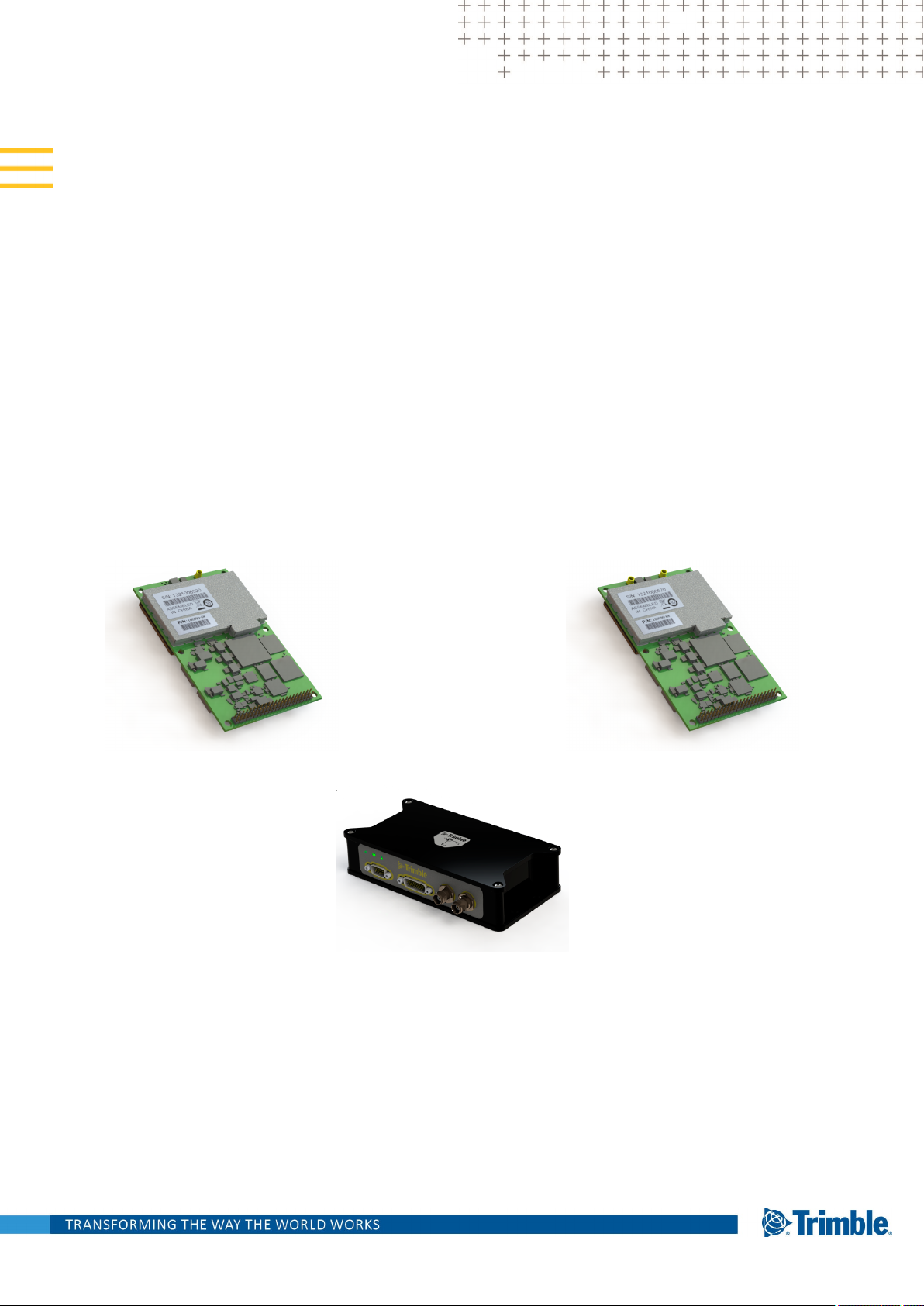
About the BD990 GNSS receiver
The Trimble BD990 receiver is part of a family of receivers that support advanced
functionality. In the same mechanical footprint and pin-out as the Trimble BD970, industry
professionals trust Trimble embedded positioning technologies as the core of their
precision applications. Moving the industry forward, the Trimble BD990 redefines highperformance positioning.
This receiver is used for a wide range of
precise positioning and navigation
applications. These uses include unmanned
vehicles and port and terminal equipment
automation, and any other application
requiring reliable, centimeter-level
positioning at a high update rate and low
latency.
The receiver offers centimeter-level accuracy
based on carrier phase RTK and submeter
accuracy code-based solutions.
Automatic initialization and switching between positioning modes allow for the best
position solutions possible. Low latency (less than 20 ms) and high update rates give the
response time and accuracy required for precise dynamic applications.
The receiver can be configured as an autonomous base station (sometimes called a
reference station) or as a rover receiver (sometimes called a mobile receiver). Streamed
outputs from the receiver provide detailed information, including the time, position,
heading, quality assurance (figure of merit) numbers, and the number of tracked satellites.
The receiver also outputs a one pulse-per-second (1 PPS) strobe signal which lets remote
devices precisely synchronize time.
Designed for reliable operation in all environments, the receiver provides a positioning
interface to an office computer, external processing device, or control system. The receiver
can be controlled through a serial, ethernet, USB, or CAN port using binary interface
commands or the web interface.
BD99x Series and BX992 GNSS Receiver ModuleUser Guide | 10
Page 11

1 Introduction
About the BD992 GNSS receiver
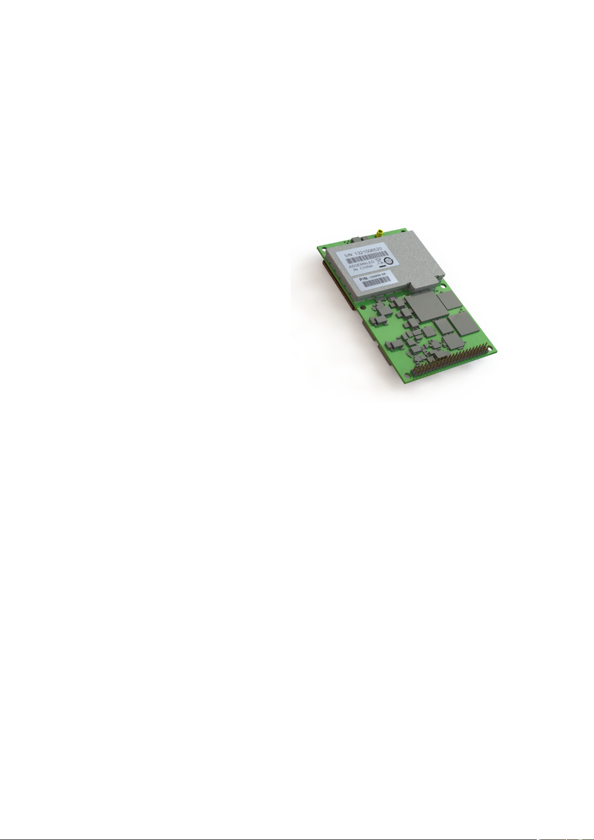
This receiver is used for a wide range of precise positioning and navigation applications.
These uses include unmanned vehicles and port and terminal equipment automation, and
any other application requiring reliable, centimeter-level positioning at a high update rate
and low latency.
The receiver offers centimeter-level accuracy
based on carrier phase RTK and submeter
accuracy code-based solutions.
Automatic initialization and switching
between positioning modes allow for the
best position solutions possible. Low latency
(less than 20 ms) and high update rates give
the response time and accuracy required for
precise dynamic applications.
The receiver can be configured as an
autonomous base station (sometimes called
a reference station) or as a rover receiver (sometimes called a mobile receiver). Streamed
outputs from the receiver provide detailed information, including the time, position,
heading, quality assurance (figure of merit) numbers, and the number of tracked satellites.
The receiver also outputs a one pulse-per-second (1 PPS) strobe signal which lets remote
devices precisely synchronize time.
Designed for reliable operation in all environments, the receiver provides a positioning
interface to an office computer, external processing device, or control system. The receiver
can be controlled through a serial, ethernet, USB, or CAN port using binary interface
commands or the web interface.
BD99x Series and BX992 GNSS Receiver ModuleUser Guide | 11
Page 12
1 Introduction
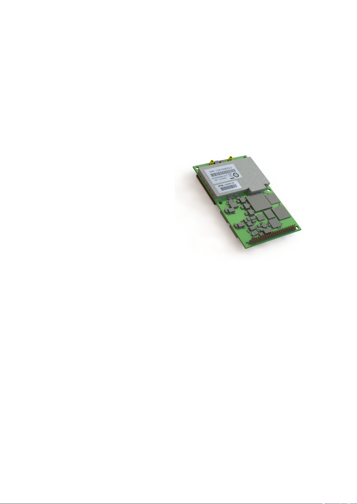
About the BD992-INS GNSS receiver
The Trimble® BD992-INS receiver contains a powerful multi-constellation, multi-frequency
GNSS receiver with on-board integrated inertial sensors. Taking advantage of Trimble’s
expertize in both GNSS and Inertial technology the BD992-INS receiver has been designed
for applications requiring continuous centimeter accuracy in a compact package. By
integrating inertial sensors on the same module, robust high accuracy positions are
produced in all environments. A simple intuitive web interface and interface protocol
allows a variety of dynamic models to be supported.
The GNSS components are fully shielded.
This design ensures that the high quality
signals are protected from the sources of
EMI on the host platform.
The BD992-INS supports both the triple
frequency for the GPS and GLONASS
constellations, and the dual frequency from
BeiDou and Galileo. As the number of
satellites in the constellations grows, the
BD992-INS is ready to take advantage of the
additional signals. This delivers the quickest
and most reliable RTK initializations for 1 to 2
centimeter positioning. For applications that do not require centimeter accuracy, the
BD992-INS integrated GNSS-Inertial engine delivers high accuracy GNSS/DGNSS positions
in the most challenging environments such as urban canyons.
Different configurations are available. These include everything from a DGPS L1 unit
through to a four-constellation triple-frequency RTK unit. Choose the configuration that
suits your requirements. All features are password-upgradeable, allowing functionality to
be upgraded as your requirements change.
The receiver also supports Fault Detection and Exclusion (FDE) and Receiver, and
Autonomous Integrity Monitoring (RAIM) for safety-critical applications.
Key features include:
l High update rate position and orientation solutions
l Continuous positioning in GNSS denied environments
l Lever arm calculation from antenna to navigation point of interest
l Robust Moving Baseline RTK for precision landing on moving platforms
l Single antenna heading not influenced by magnetic field variations
BD99x Series and BX992 GNSS Receiver ModuleUser Guide | 12
Page 13
1 Introduction
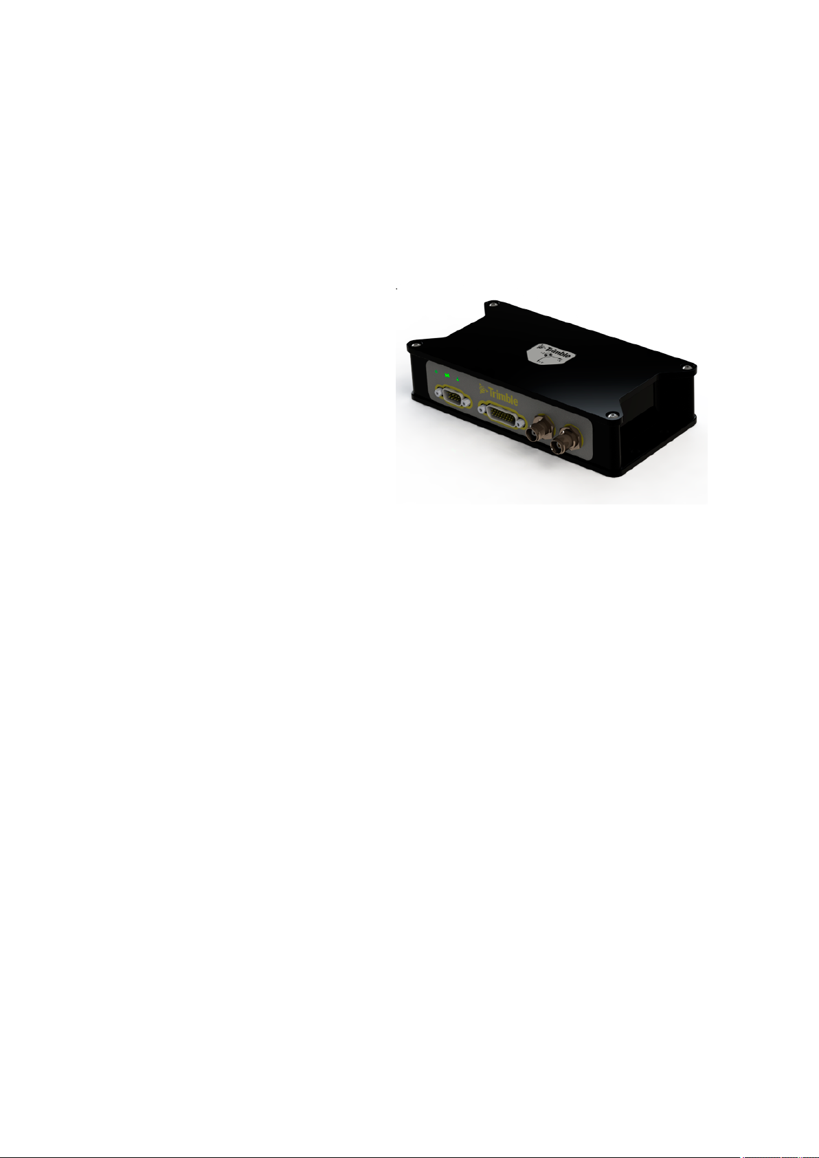
About the BX992 receiver
The BX992 receiver enclosure allows OEM, a system integrator or end users to rapidly
integrate high accuracy GNSS into their applications. The BX992 is ideal as a base station, a
moving base, a rover or for applications that require precise heading in addition to
accurate positions.
The receiver provides reliable operation in
all environments, and a positioning interface
to an office computer, external processing
device, or control system. You can control
the receiver through a serial or Ethernet
port using binary interface commands or
web interface.
BD99x Series and BX992 GNSS Receiver ModuleUser Guide | 13
Page 14

1 Introduction
About the Trimble Maxwell 7 technology
The Trimble BD990/BD992 GNSS products and the INS variant supports triple-frequency
for the GPS, GLONASS, BeiDou and Galileo constellations. As the number of satellites in the
constellations grows the receiver is ready to take advantage of the additional signals. This
delivers the quickest and most reliable RTK initializations for centimeter positioning. With
the latest Trimble Maxwell™ 7 Technology, the receivers provide:
l 336 tracking channels
l Trimble EVEREST™ Plus multipath mitigation
l Advanced RF Spectrum Monitoring and Analysis
l Proven low-elevation tracking technology
With the option of utilizing OmniSTAR or RTX services, the GNSS receivers delivers varying
levels of performance down to centimeter level without the use of a base station.
Flexible interfacing
The BD990 and BD992 GNSS products are designed for easy integration and rugged
dependability. Customers benefit from the Ethernet connectivity available on the board,
allowing high speed data transfer and configuration via standard web browsers. USB and
RS-232 are also supported. Just like other Trimble embedded technologies; easy to use
software commands simplify integration and reduce development times.
Different configurations of the module are available. These include everything from a DGPS
L1 unit all the way to a four-constellation triple-frequency RTK unit. All features are
password-upgradeable, allowing functionality to be upgraded as your requirements
change.
Typical applications
The receiver can be used in a multitude of applications that require robust high precision
positioning. The receiver can be used within systems being developed for:
l Precision agriculture
l Autonomous vehicles
l Unmanned aircrafts
l Field robotics
l Machine guidance and control
l Timing
BD99x Series and BX992 GNSS Receiver ModuleUser Guide | 14
Page 15

1 Introduction
l Construction
l GNSS heading and attitude measurements for marine equipment
The receiver can be set up and installed as:
l an on-board GNSS rover in SBAS DGPS mode.
l an on-board GNSS rover connected to an external communication device (radio,
GPRS, CDMA) and used in DGPS, Flying RTK or RTK mode.
l a low-cost solution for vector determination applications.
l a relative positioning combined with an absolute RTK position (machine guidance and
control).
l a relative movement monitoring, heave compensation, wing deformation, and so forth.
BD99x Series and BX992 GNSS Receiver ModuleUser Guide | 15
Page 16

1 Introduction
Features
The following features are applicable to these receivers.
Technical specifications
l Trimble Maxwell™ 7 technology
l On-board Advanced MEMS inertial sensors (applicable to BD992-INS and BX992 only)
l 336 tracking channels
l GPS: L1 C/A, L2E, L2C, L5
l BeiDou: B1, B2
l GLONASS: L1 and L2 C/A, L3 CDMA13
l Galileo2: E1, E5A, E5B, E5AltBOC
l IRNSS L5
l QZSS: L1 C/A, L1 SAIF, L2C, L5, LEX
l SBAS: L1 C/A, L5
l MSS L-Band: OmniSTAR, Trimble RTX
l High precision multiple correlator for GNSS pseudorange measurements
l Trimble EVEREST™ Plus multipath mitigation
l Advanced RF Spectrum Monitoring and Analysis
l Unfiltered, unsmoothed pseudorange measurement data for low noise, low multipath
error, low time domain correlation and high dynamic response
l Very low noise GNSS carrier phase measurements with <1 mm precision in a 1 Hz
bandwidth
l Proven Trimble low elevation tracking technology
l Reference outputs/inputs: CMR, CMR+™, sCMRx, RTCM 2.1, 2.2, 2.3, 2.4, 3.0, 3.112, 3.2.
NOTE – The functionality to input or output any of these corrections depends on the installed
options.
NOTE – Different manufacturers may have established different packet structures for their
correction messages. Thus, the receiver may not receive corrections from another
manufacturer's receiver, and another manufacturer's receiver may not be able to receive
corrections from the receiver.
BD99x Series and BX992 GNSS Receiver ModuleUser Guide | 16
Page 17

1 Introduction
l Navigation outputs:
l ASCII: NMEA-0183: GBS; GGA; GLL; GNS; GRS; GSA; GST; GSV; HDT; LLQ; AVR; GDP;
DTM; BPQ; GGK; PJK; PJT; VGK; VHD; RMC; ROT; VTG; ZDA.
l Binary: Trimble GSOF, NMEA 2000
NOTE – Galileo support is developed under a license of the European Union and the European
Space Agency.
NOTE – There is no public GLONASS L3 CDMA ICD. The current capability in the receivers is
based on publicly available information. As such, Trimble cannot guarantee that these receivers
will be fully compatible.
l 1 pulse-per-second (1PPS) output
l Event Marker Input support
l Supports Fault Detection and Exclusion (FDE), Receiver Autonomous Integrity
Monitoring (RAIM)
Communication
l 1 USB 2.0 device port
l 1 LAN Ethernet port
l All functions are performed through a single IP address simultaneously—including
web interface access and raw data streaming
l Network protocols supported:
l HTTP (web interface)
l NTP Server
l NMEA, GSOF, CMR over TCP/IP or UDP
l NTripCaster, NTripServer, NTripClient
l mDNS/uPnP Service discovery
l Dynamic DNS
l eMail alerts
l Network link to Google Earth
l Support for external modems through PPP
l RDNIS support
l 2 x RS-232 ports (baud rates up to 460,800)
l 1 x CAN port
l Control Software: HTML web browser, Internet Explorer, Firefox, Safari, Opera, Google
Chrome
BD99x Series and BX992 GNSS Receiver ModuleUser Guide | 17
Page 18

1 Introduction
Default settings
All settings are stored in application files. The default application file, Default.cfg, is stored
permanently in the receiver, and contains the factory default settings. Whenever the
receiver is reset to its factory defaults, the current settings (stored in the current
application file, Current.cfg) are reset to the values in the default application file.
These settings are defined in the default application file.
Function Settings Factory default
SV Enable - All SVs enabled
General Controls Elevation mask 10°
PDOP mask 99
RTK positioning mode Low Latency
Motion Kinematic
Ports Baud rate 38,400
Format 8-None-1
Flow control None
Input Setup Station Any
NMEA/ASCII (all supported messages) All ports Off
Streamed Output All types Off
Offset=00
RT17/Binary All ports Off
Reference Position Latitude 0°
Longitude 0°
Altitude 0.00 m HAE
Antenna Type Unknown
Height (true vertical) 0.00 m
Measurement method Antenna Phase Center
1PPS Disabled
Event Ports Disabled
BD99x Series and BX992 GNSS Receiver ModuleUser Guide | 18
Page 19

1 Introduction
If a factory reset is performed, the above defaults are applied to the receiver. The receiver
also returns to a DHCP mode, and security is enabled (with a default login of admin and the
password of password). To perform a factory reset:
l From the web interface, select Receiver Configuration / Reset and then clear the Clear
All Receiver Settings option.
l Send the Command 58h with a 03h reset value.
l Use the Configuration Toolbox utility and from the Communications menu, select
Reset Receiver. Select both the Erase Battery-Backed RAM and Erase File System
options.
BD99x Series and BX992 GNSS Receiver ModuleUser Guide | 19
Page 20
1 Introduction
BD990 and BD992 flavors
All the flavors are configured to output at 20 Hz. 50 Hz or 100 HZ are available as an
upgrade.
RTK
BD9 90 BD992 Heading MSS GPS GLONASS Galileo Beidou L1 L2 L5 Base Rover
100990-01 1100992-01 1
100990-02 2100992-02 2
100990-03 3100992-03 3
100990-04 4100992-04 4
100990-05 5100992-05 5
100990-06 6100992-06 6
100990-07 4100992-07 4
100990-08 41009902-08 4
100990-22 2
100990-23 3
100990-24 4
100990-25 5
1
Unconfigured
2
Autonomous/SBAS
3
DGPS
4
RTK 1 cm
5
30 cm limit
6
10 cm limit
BD99x Series and BX992 GNSS Receiver ModuleUser Guide | 20
Page 21

1 Introduction
BD992-INS and BD992 flavors
All the flavors are configured to output at 20 Hz. 50 Hz or 100 HZ are available as an
upgrade.
RTK
BD9 90 BD99 2 Heading MSS GP S GLONASS Galileo Beidou L1 L2 L5 Base Rover
100990-01 1100992-01 1
100990-02 2100992-02 2
100990-03 3100992-03 3
100990-04 4100992-04 4
100990-05 5100992-05 5
100990-06 6100992-06 6
100990-07 4100992-07 4
100990-08 41009902-08 4
100990-22 2
100990-23 3
100990-24 4
100990-25 5
1
Unconfigured
2
Autonomous/SBAS
3
DGPS
4
RTK 1 cm
5
30 cm limit
6
10 cm limit
BD99x Series and BX992 GNSS Receiver ModuleUser Guide | 21
Page 22

1 Introduction
Receiver hardware and accessories
The following support hardware and accessories can be ordered for the BD990, BD992,
and BD992-INS:
Part number Description
112076-00 Trimble BD99x Evaluation Kit (receiver not included)
105679-00-B Trimble BD99x Interface board
A02503 18 V Power Supply, 3 Ah
A02584 CBL ASSY TNC-MMCX
The following support hardware and accessories can be ordered for the BX992:
Part number Description
A02503 18 V Power Supply, 3 Ah
57168-INT DB26 to DB9, Ethernet and Power adapter
77070-00-INT Cable DB26 to Power, 1PPS, DB9F, DB9M, USB, RJ45M
Evaluation kit
For system integrators/evaluators, Trimble offers an evaluation kit for the BD990, BD992,
and BD992-INS receivers. This kit comes with a specially designed board that can mate with
the receiver. Once mated, the evaluation board provides the integrator or tester with a
platform to gain an in-depth understanding of the receiver. It also allows for development
of custom applications that can effectively implement the precision GNSS information that
the receiver is capable of outputting. The evaluation board gives access to the following;
l Power connector
l Four serial ports through 2 × DB9 and 2 × USB Type-B connectors
l Ethernet through 1 × RJ45 connector
l Three USB ports through 2 × Type-A and 1 × Type-B receptacles
l Three LEDs to indicate satellite tracking, receipt of corrections and power
For more information, see Evaluation Board, page 44.
BD99x Series and BX992 GNSS Receiver ModuleUser Guide | 22
Page 23

1 Introduction
Upgrade options
The following support hardware and accessories apply to all the receivers.
Part number Description
106781-01 Trimble BD990 Configuration Field Upgrade 1
106782 50 Hz Output Rate Field Upgrade
106783 100 Hz Output Rate Field Upgrade (applicable only to BD992-INS and
BX992)
106784 GLONASS Field Upgrade
106785 Galileo Field Upgrade
106786 BeiDou Field Upgrade
For details about ordering these upgrades for your receiver, please email
GNSSOEMSales@trimble.com. Your regional sales manager would be happy to assist you
in upgrading your receiver with the options of your choice.
BD99x Series and BX992 GNSS Receiver ModuleUser Guide | 23
Page 24

1 Introduction
Compatible antennas
It is always recommended that a Trimble tested and compatible Trimble antenna is used
with the receivers. You may use other antennas but ensure that these antennas support
the correct frequencies enabled on the receiver. Furthermore, be aware of the minimum
LNA gain on the receivers is 31 dB.
The following list shows a list of recommended antennas and their part numbers.
P/N Description
105000-50-INT Zephyr™ Model 3, L1/L2/L5 Rover
115000-50-INT Zephyr Model 3 L1/L3/L5 Base
C02817 L1/L2 Aviation Antenna (TSO Certified)
C02992 Trimble AV59 L1/L2/L5/G1/G2/L-Band Aviation Antenna (Not TSO
Certified)
C03167 Trimble LV59 L1/L2/L5/G1/G2/ L-Band Antenna (Not TSO Certified)
5/8 Mount
105728 Trimble AV39 L1/L2/L5/G1/G2/ L-Band Aviation Antenna Antenna
(TSO Certified/US sales)
105728-10 Trimble AV39 L1/L2/L5/G1/G2/ L-Band Aviation Antenna Antenna
(TSO Certified/Non US sales)
112735 Trimble AV28 L1/L2/L5 L-band Aviation Antenna
83553 Trimble AV33 L1/G1 Aviation Antenna
86362 Trimble AV34 L1/L2/G1/G2 Aviation Antenna
99038-00-INT Trimble AG25 L1/L2/L5/G1/G2/ L-Band Antenna
99810-30-INT Trimble GA810 GNSS L-Band Antenna
44830-00-INT Trimble GA830 GNSS L-Band Antenna
BD99x Series and BX992 GNSS Receiver ModuleUser Guide | 24
Page 25

The following cables and accessories may be purchased with the antenna:
P/N Description
58957-05-INT 5 m TNC-TNC Antenna Cable
A02500 10 m TNC-TNC Antenna Cable 1
92296-10-INT 10 m TNC-TNC LMR400 Antenna Cable
A02501 30 m TNC-TNC Antenna Cable
A02584 CBL ASSY TNC-MMCX
F00922 Zephyr Mounting Bracket
84902 AV33/34 Antenna Bracket
86693 Mag mount with 5/8" x 11 bolt
1 Introduction
Technical support
If you have a problem and cannot find the information you need in the product
documentation, send an email to GNSSOEMSupport@trimble.com.
Documentation, firmware, and software updates are available at:
www.intech.trimble.com/support/oem_gnss/receivers/trimble.
BD99x Series and BX992 GNSS Receiver ModuleUser Guide | 25
Page 26

Specifications
Positioning specifications
Performance specifications
Physical and electrical characteristics
Environmental specifications
Receiver pinout information
Mechanical specifications
Power input
Communication specifications
2
This chapter details the specifications for the receiver.
Specifications are subject to change without notice.
BD99x Series and BX992 GNSS Receiver ModuleUser Guide | 26
Page 27

2 Specifications
Positioning specifications
NOTE – The following specifications are provided at 1 sigma level when using a Trimble Zephyr 2
antenna. These specifications may be affected by atmospheric conditions, signal multipath, and
satellite geometry. Initialization reliability is continuously monitored to ensure highest quality.
BD990/BD992
Feature Specification
Initialization time Typically <8 seconds
Initialization accuracy >99.9%
Mode Accuracy Latency (at max. output
rate)
Single Baseline
RTK (<30 km)
0.008 m + 1 ppm
horizontal
<20 ms 50 Hz
0.015 m + 1 ppm vertical
DGPS 0.25 m + 1 ppm
horizontal
<20 ms 50 Hz
0.5 m + 1 ppm vertical
1
SBAS
0.5 m horizontal
<20 ms 50 Hz
0.85 m vertical
Autonomous 1.00 m horizontal
<20 ms 50 Hz
1.5 m vertical
Maximum
Rate
1
GPS only and depends on SBAS system performance. FAA WAAS accuracy specifications are <5m
3DRMS.
BD99x Series and BX992 GNSS Receiver ModuleUser Guide | 27
Page 28

2 Specifications
Performance specifications
NOTE – The Time to First Fix specifications are typical observed values. A cold start is when the
receiver has no previous satellite (ephemerides/almanac) or position (approximate position or time)
information. A warm start is when the ephemerides and last used position is known.
BD990 and BD992
Feature Specification
Time to First Fix (TFF) Cold Start <45 seconds
Warm Start <30 seconds
Signal Re-acquisition <2 seconds
Velocity Accuracy
1
Horizontal 0.007 m/sec
Vertical 0.020 m/sec
Maximum Operating Limits
2
Velocity 515 m/sec
Altitude 18,000 m
Acceleration 11 g
RTK initialization time Typically <8 seconds
RTK initialization reliability >99%
Position latency <20 ms
Maximum position/attitude update rate 50 Hz
1
1 sigma level when using a Trimble Zephyr 2 antenna. These specifications may be affected by
atmospheric conditions, signal multipath, and satellite geometry. Initialization reliability is
continuously monitored to ensure highest quality.
2
As required by the US Department of Commerce to comply with export licensing restrictions.
BD99x Series and BX992 GNSS Receiver ModuleUser Guide | 28
Page 29

BD992-INS and BX992
Feature Specification
Initialization time Typically <8 seconds
Initialization accuracy >99.9%
2 Specifications
Mode Accuracy Latency (at max. output
rate)
Single Baseline RTK
(<30 km)
0.008 m + 1 ppm
horizontal
<20 ms 50 Hz
0.15 m + 1 ppm vertical
DGPS 0.25 m + 1 ppm
horizontal
0.5 m + 1 ppm vertical
<20 ms 50 Hz
0.5° True Heading
1
SBAS
0.5 m horizontal
<20 ms 50 Hz
0.85 m vertical
Autonomous 1.00 m horizontal
<20 ms 50 Hz
1.50 m vertical
INS-Autonomous 1.00 m horizontal
<20 ms 50 Hz
1.50 m vertical
Maximum
rate
roll/pitch 0.1°
Heading 2 m Baseline 0.09°
INS-SBAS
0.50 m horizontal
<20 ms 50 Hz
0.85 m vertical
roll/pitch 0.1°
Heading 2 m Baseline 0.09°
1
As required by the US Department of Commerce to comply with export licensing restrictions.
BD99x Series and BX992 GNSS Receiver ModuleUser Guide | 29
Page 30

Feature Specification
INS-DGNSS 0.40 m horizontal
<20 ms 50 Hz
0.60 m vertical
roll/pitch 0.1°
Heading 2 m Baseline 0.09°
2 Specifications
INS-RTK
0.05 m horizontal
<20 ms 50 Hz
0.03 m vertical
roll/pitch 0.1°
Heading 2 m Baseline 0.09°
BD99x Series and BX992 GNSS Receiver ModuleUser Guide | 30
Page 31

Physical and electrical characteristics
Feature BD990 BD992/BD992-INS BX992
2 Specifications
Dimensions
(L × W × H)
Power 3.3 V DC +5%/–3%
Weight 54 grams 62 grams .75 kg
Connectors - I/O
Connectors Antenna
Antenna LNA
Power Output
100 mm × 60 mm × 11.6 mm 185 mm × 93 mm × 43 mm
9 V to 30 V DC external
Typically, 1.45 W (L1/L2 GPS)
Typically, 1.55 W (L1/L2 GPS and G1/G2
GLONASS)
Typically, 2.35 W (L1/L2/L5 GPS, G1/G2
GLONASS, B1/B2 BeiDou, L1/E5 Galileo)
44-pin Header
1 × MMCX
receptacle
2 × MMCX
receptacles
Input voltage: 3.3 to 5 V DC
Maximum current: 400 mA
power input with overvoltage protection
Maximum 4.1 W (with both
antennas connected)
2 × DB9
1 × DB26
TNC Female
Minimum
required LNAgain
32 dB
NOTE – This receiver is designed to operate with the Zephyr Model 2
antenna which has a gain of 50 dB. Higher-gain antennas have not been
tested.
BD99x Series and BX992 GNSS Receiver ModuleUser Guide | 31
Page 32

Environmental specifications
Feature Specification
Temperature Operating: -40 °C to 75 °C (-40 °F to 167 °F)
Storage: -55 °C to 85 °C (-67 °F to 185 °F)
Vibration MIL810F, tailored
Random 6.2 gRMS operating
Random 8 gRMS survival
Mechanical shock MIL810D
+/- 40 g operating
+/- 75 g survival
Operating humidity 5% to 95% R.H. non-condensing, at +60 °C (140 °F)
2 Specifications
Communication specifications
Feature Specification
Communications 1 LAN port
Supports links to 10BaseT/100BaseT networks.
All functions are performed through a single IPaddress
simultaneously including web interface access and data
streaming.
2 × RS-232 ports
Baud rates up to 460,800
1 USB 2.0 port
Receiver position update
rate
Correction data input CMR, CMR+™, sCMRx, RTCM 2.0–2.4, RTCM 3.x, 3.2
Correction data output CMR, CMR+, sCMRx, RTCM 2.0 DGPS (select RTCM 2.1), RTCM
1 Hz, 2 Hz, 5 Hz, 10 Hz, 20 Hz, and 50 Hz positioning
2.1–2.4, RTCM 3.x, 3.2
Data outputs 1PPS, NMEA, Binary GSOF, ASCIITime Tags
BD99x Series and BX992 GNSS Receiver ModuleUser Guide | 32
Page 33

2 Specifications
Receiver pinout information
BD990/BD992/BD992-INS 44-pinout connector
Pin Usage Integration notes
1 GND
2 RTKLED
3 Power Switch *** Low = on, High = off, 1 Mohm pulldown
4 PPS Out
5 Power In 3.3 VDC
6 Power In 3.3 VDC
7 COM3 RX or CAN RX or EVENT 1 3.3 V level, multiplexed
8 EVENT 0
9 Power LED
10 Satellite LED
11 COM2 CTS 3.3 V level
12 RESET IN *** Low = reset, NC = normal function, 100 k
pullup
13 COM2 RTS 3.3 V level
14 COM2 RX 3.3 V level
15 COM1 CTS RS232 RS-232 level
16 COM2 TX 3.3 V level
17 COM1 RTS RS232 RS-232 level
18 COM1 RX RS232 RS-232 level
19 COM3 TX or CAN TX 3.3 V level, multiplexed
20 COM1 TX RS232 RS-232 level
21 USB DM
22 USB DP
BD99x Series and BX992 GNSS Receiver ModuleUser Guide | 33
Page 34

Pin Usage Integration notes
23 GND
24 GND
25 RESERVED USB ID
26 RESERVED USB VBUS
27 ETHERNET RD-
28 ETHERNET RD+
29 NC
30 ETHERNET TD+
31 ETHERNET TD-
32 NC
2 Specifications
33 VOUT 3.3 VDC
34 NC
35 RESERVED I2C SCL
36 RESERVED I2C SDA
37 DMI1
38 DMI2
39 GND
40 GND
41 10 MHz in
42 Enable external 10 MHZ High = external enabled, low or NC =
internal TCXO enabled. 10 k pulldown
43 IMULED
44 GND
44-pin connector details
MFG - SAMTEC (P/N TMM-122-03-S-D)
Recommended mating connector
MFG - SAMTEC (P/N SQW-122-01-L-D)
BD99x Series and BX992 GNSS Receiver ModuleUser Guide | 34
Page 35

BX992 connectors
DB26 pin out connector
Pin Usage
1 Power OFF (disconnected)
2 Clear to send (CTS) input for COM Port 2
3 Event 0 input
4 Event 1 input
2 Specifications
5 Not connected
6 Common ground
7 Transmit data for COMPort 1
8 Receiver data for COMPort 1
9 USB +
10 Ethernet ground (ET GND RJ45 Pin 4)
11 Ready to send (RTS) output for COMPort 2
12 Transmit data for COM Port 2
13 Ethernet spare (ETGND RJ45 Pin 5)
14 Ethernet spare (ETGND RJ45 Pin 8)
15 USB ID
16 Ethernet receive data- (RD- RJ45 Pin 6)
17 Ethernet transmit data- (TD- RJ45 Pin 2)
18 USBD-
19 USB Power
20 1PPS
BD99x Series and BX992 GNSS Receiver ModuleUser Guide | 35
Page 36

Pin Usage
21 Receive data for COM Port 2
22 Ethernet ground (ETGND RJ45 Pin 7)
23 Common ground
24 DC power in, 9–28 V DC (Ground is Shell)
25 Ethernet receive data+ (RD+ RJ45 Pin 3)
26 Ethernet transmit data+ (TD+ RJ45 Pin 1)
DB9 pin out connector
2 Specifications
NOTE – The DB9 port on the BX992 is not mutliplexed to output RS-232 OR CAN. This port can only
output CAN.
BD99x Series and BX992 GNSS Receiver ModuleUser Guide | 36
Page 37

2 Specifications
Mechanical specifications
If you require a 3D CAD model of the module, please send a request to
GNSSOEMSupport@trimble.com.
Key dimensions on the BD990/BD992/BD992-INS
Board dimensions are similar between the BD990 and the BD992/BD992-INS. The key
difference between the three receivers is the lack of a second MMCX receptacle on the
BD990.
Below is an overview of key dimensions on the BD990/BD992/BD992-INS.
BD99x Series and BX992 GNSS Receiver ModuleUser Guide | 37
Page 38

2 Specifications
BD992-INS Center of Navigation
The following figure details the location of the center of navigation of the BD992-INS board.
To correctly configure the inertial system, all GNSS Lever arm measurements must be
taken with respect to the BD992-INS center of navigation.
BD99x Series and BX992 GNSS Receiver ModuleUser Guide | 38
Page 39

Key dimensions on the BX992
Below is an overview of key dimensions on the BX992.
2 Specifications
Power input
Item Description
Power
requirement
The unit, excluding the antenna, operates at 3.3 V +5%/-3%. The 3.3
V should be able to supply 2.0 A of surge current. The typical power
consumption based on band usage is:
l L1/L2 GPS + GLONASS = 2.0 W
l L1/L2/L5 GPS + GLONASS + BeiDou + Galileo = 2.5 W
BD99x Series and BX992 GNSS Receiver ModuleUser Guide | 39
Page 40

Installation
Unpacking and inspecting the shipment
Installation guidelines
Follow the guidelines in this chapter for installing and mounting the receiver.
3
BD99x Series and BX992 GNSS Receiver ModuleUser Guide | 40
Page 41

3 Installation
Unpacking and inspecting the shipment
Visually inspect the shipping cartons for any signs of damage or mishandling before
unpacking the receiver. Immediately report any damage to the shipping carrier.
Shipment carton contents
The shipment will include one or more cartons depending on the number of optional
accessories ordered. Open the shipping cartons and make sure that all of the components
indicated on the bill of lading are present.
Reporting shipping problems
Report any problems discovered after you unpack the shipping cartons to both Trimble
Customer Support and the shipping carrier.
Trimble’s customer support for the GNSS receiver can be reached at
GNSSOEMsupport@trimble.com.
BD99x Series and BX992 GNSS Receiver ModuleUser Guide | 41
Page 42

3 Installation
Installation guidelines
In order for the receivers to perform optimally, the following precautions should be taken
or followed.
Considering environmental conditions
Install the receiver in a location situated in a dry environment. Avoid exposure to extreme
environmental conditions. This includes:
l Water or excessive moisture
l Excessive heat greater than 75 °C (167 °F)
l Excessive cold less than –40 °C (–40 °F)
l Corrosive fluids and gases
Avoiding these conditions improves the receiver’s performance and long-term product
reliability.
Sources of electrical interference
Avoid the following sources of electrical and magnetic noise:
l Gasoline engines (spark plugs)
l Television and computer monitors
l Alternators and generators
l Electric motors
l Propeller shafts
l Equipment with DC-to-AC converters
l Fluorescent lights
l Switching power supplies
Mounting the antennas
Choosing the correct location for the antenna is critical for a high quality installation. Poor
or incorrect placement of the antenna can influence accuracy and reliability and may result
in damage during normal operation. Follow these guidelines to select the antenna location:
l If the application is mobile, place the antenna on a flat surface along the centerline of
the vehicle.
l Choose an area with clear view to the sky above metallic objects.
BD99x Series and BX992 GNSS Receiver ModuleUser Guide | 42
Page 43

3 Installation
l
Avoid areas with high vibration, excessive heat, electrical interference, and strong
magnetic fields.
l
Avoid mounting the antenna close to stays, electrical cables, metal masts, and other
antennas.
l
Avoid mounting the antenna near transmitting antennas, radar arrays, or satellite
communication equipment.
Connecting the antenna cable
1. After mounting the antenna, route the antenna cable from the GPS antenna to the
receiver.
Avoid the following hazards when routing the antenna cable:
l Sharp ends or kinks in the cable
l Hot surfaces (such as exhaust manifolds or stacks)
l Rotating or reciprocating equipment
l Sharp or abrasive surfaces
l Door and window jams
l Corrosive fluids or gases
2. After routing the cable, connect it to the receiver. Use tie-wraps to secure the cable at
several points along the route. For example, to provide strain relief for the antenna
cable connection, use a tie-wrap to secure the cable near the base of the antenna.
NOTE – When securing the cable, start at the antenna and work towards the receiver.
3. When the cable is secured, coil any slack. Secure the coil with a tie-wrap and tuck it in a
safe place.
BD99x Series and BX992 GNSS Receiver ModuleUser Guide | 43
Page 44

4
Evaluation Board
BD990/BD992/BD992-INS evaluation board layout
LED functionality and operation
BD992-INS IMU LED
This chapter provides an overview of the evaluation board. An evaluation kit is available for
testing the receiver. The evaluation board has three LEDs to indicate satellite tracking, RTK
receptions, and power. The evaluation board also has a unique configuration to control
the voltage sent to the antenna.
BD99x Series and BX992 GNSS Receiver ModuleUser Guide | 44
Page 45

4 Evaluation Board
BD990/BD992/BD992-INS evaluation board layout
Current or prospective customers can obtain schematic drawings of the evaluation I/O
board by contacting GNSSOEMSupport@trimble.com.
BD99x Series and BX992 GNSS Receiver ModuleUser Guide | 45
Page 46

4 Evaluation Board
LED functionality and operation
The evaluation interface board comes with three LEDs to indicate satellite tracking, RTK
reception, and power. The initial boot-up sequence for a receiver lights all the three LEDs
for about three seconds followed by a brief duration where all three LEDs are off.
Thereafter, use the following table to confirm tracking of satellite signals or for basic
troubleshooting.
For single antenna configurations, the following LED patterns apply:
Power LED RTK Corrections
LED
On
Off Off The receiver is turned on, but not
(continuous)
On
Off Blinking at 1 Hz The receiver is tracking satellites, but
(continuous)
On
Blinking at 1 Hz Blinking at 1 Hz The receiver is tracking satellites and
(continuous)
On
(continuous)
Off or Blinking
(receiving
corrections)
On
Blinking at 1 Hz Off The receiver is receiving incoming
(continuous)
SV Tracking
LED
Blinking at 5 Hz
for a short
while
Status
tracking satellites.
no incoming RTK corrections are
being received.
receiving incoming RTK corrections.
Occurs after a power boot sequence
when the receiver is tracking less
than 5 satellites and searching for
more satellites.
RTK corrections, but not tracking
satellites.
On
(continuous)
On
(continuous)
Blinking at 5 Hz Blinking at 1 Hz The receiver is receiving Moving
Base RTK corrections at 5 Hz.
On (continuous) Blinking at 1 Hz The receiver is receiving Moving
Base RTK corrections at 10 or 20 Hz
(the RTK LED turns off for 100 ms if a
correction is lost).
On
(continuous)
On, Blinking off
briefly at 1 Hz
Blinking at 1 Hz The receiver is in a base station
mode, tracking satellites and
transmitting RTK corrections.
On Blinking at 1 Hz On The receiver is in Boot Monitor
BD99x Series and BX992 GNSS Receiver ModuleUser Guide | 46
Page 47

4 Evaluation Board
Power LED RTK Corrections
LED
(continuous) (continuous) Mode. Use the WinFlash utility to
SV Tracking
LED
Status
reload application firmware onto the
board. For more information,
contact technical support.
BD992-INS IMU LED
The BD992-INS evaluation board has an additional LED that functions only when a BD992INS is plugged in. This blue led shows the IMU status. The following table shows the
different modes of this LED:
IMU navigation status LED behavior
Signal status unknown or no GNSS/INSS solution LED is off
Coarse leveling LED blinks at 5 Hz
Degraded solution LED blinks at 2 Hz
Aligned solution LED blinks at 1 Hz
BD99x Series and BX992 GNSS Receiver ModuleUser Guide | 47
Page 48

GNSS and RTKBasics
Autonomous GNSS
SBAS
DGPS/DGNSS
RTK
Carrier phase initialization
Update rate and latency
Data link
Moving baseline RTK positioning
5
Critical factors affecting RTK accuracy
Antenna Phase Centers
In order to understand how to set up Trimble’s GNSS and inertial systems, this chapter
describes the basics of the different protocols, various terminologies, and concepts that
are used.
BD99x Series and BX992 GNSS Receiver ModuleUser Guide | 48
Page 49

5 GNSS andRTKBasics
Autonomous GNSS
Autonomous or standalone GNSS operation uses radio signals from GNSS satellites alone.
No other sources of augmentation or correction are used in the position computation.
While this is theoretically the poorest accuracy mode of GNSS, recent improvements in
satellite orbits and receiver performance result in positions close to one meter in accuracy.
Autonomous GNSS provides robust positioning as it is does not rely on the reception of
data from secondary data links.
SBAS
The receiver supports SBAS (Satellite Based Augmentation Systems) that conform to
RTCA/DO-229C, such as WAAS, EGNOS, or MSAS. The receiver can use the WAAS (Wide
Area Augmentation System) set up by the FAA (Federal Aviation Administration). WAAS was
established for flight and approach navigation for civil aviation. WAAS improves the
accuracy, integrity, and availability of the basic GPS signals over its coverage area, which
includes the continental United States and outlying parts of Canada and Mexico.
SBAS can be used in surveying applications to improve single point positioning when
starting a reference station, or when an RTK radio corrections link is down. SBAS
corrections should be used to obtain greater accuracy than autonomous positioning, not
as an alternative to RTK positioning.
The SBAS system provides correction data for visible satellites. Corrections are computed
from ground station observations and then uploaded to two geostationary satellites. This
data is then broadcast on the L1 frequency, and is tracked using a channel on the BD9xx
receiver, exactly like a GPS satellite.
For more information on WAAS, refer to the FAA home page at http://gps.faa.gov.
The receiver also contains an SBAS+ mode which allows it to use pseudoranges of satellites
for which SBAS corrections are present as well as pseudoranges from uncorrected
satellites in the position solution. The SBAS+ solution can minimize occurrences of the
solution mode switching back and forth between SBAS and Autonomous solution modes;
however, the SBAS+ position solution may perform more poorly at times because
uncorrected satellites have an influence in the position solution.
NOTE – To receive SBAS corrections, you must be within the official service volume of that SBAS
service. Receiver manufacturers often set SBAS correction volumes to be slightly larger than the ones
specified by the respective SBAS service but this may depend on each receiver manufacturer. For
example, Trimble receivers situated in the MSAS correction zones can use MSAS corrections between
the latitudes 20 and 60 degrees North and between longitudes 110 and 150 degrees East. Hence,
BD99x Series and BX992 GNSS Receiver ModuleUser Guide | 49
Page 50

5 GNSS andRTKBasics
receivers situated within this window will track and use MSAS while a receiver situated outside this
window may track but not use MSAS corrections.
DGPS/DGNSS
Differential GPS/GNSS encompasses a series of techniques that improves the relative
accuracy of GNSS by referencing to a single or network of stations. In its most common
form a fixed reference station broadcasts the difference between the measured satellite
pseudorange and the calculated pseudorange. These differences or corrections are
applied to the rover receiver pseudoranges to calculate a more accurate position.
Accuracies at the decimeter level can be achieved.
RTK
Real-Time Kinematic (RTK) positioning is positioning that is based on at least two GPS
receivers—a base receiver and one or more rover receivers. The base receiver takes
measurements from satellites in view and then broadcasts them, together with its location,
to the rover receiver(s). The rover receiver also collects measurements to the satellites in
view and processes them with the base station data. The rover then estimates its location
relative to the base.
The key to achieving centimeter-level positioning accuracy with RTK is the use of the
satellite carrier phase signals. Carrier phase measurements are like precise tape measures
from the base and rover antennas to the satellites. In the receiver, carrier phase
measurements are made with millimeter-precision. Although carrier phase measurements
are highly precise, they contain an unknown bias, termed the integer cycle ambiguity, or
carrier phase ambiguity. The rover has to resolve, or initialize, the carrier phase ambiguities
at power-up and each time the satellite signals are interrupted.
Carrier phase initialization
The receiver can automatically initialize the carrier phase ambiguities as long as at least five
common satellites are being tracked at base and rover sites. Automatic initialization is
sometimes termed On-The-Fly (OTF) or On-The-Move (OTM), to reflect that no restriction is
placed on the motion of the rover receiver throughout the initialization process.
The receiver uses L1 (or for dual-frequency receivers L1 and L2) carrier-phase
measurements plus precise code-phase measurements to the satellites to automatically
initialize the ambiguities. The initialization process generally takes a few seconds.
As long as at least four common satellites are continuously tracked after a successful
initialization, the ambiguity initialization process does not have to be repeated.
BD99x Series and BX992 GNSS Receiver ModuleUser Guide | 50
Page 51

5 GNSS andRTKBasics
TIP – Initialization time depends on baseline length, multipath, and prevailing atmospheric
errors. To minimize the initialization time, keep reflective objects away from the antennas,
and make sure that baseline lengths and differences in elevation between the base and
rover sites are as small as possible.
Update rate and latency
The number of position fixes delivered by an RTK system per second also defines how
closely the trajectory of the rover can be represented and the ease with which position
navigation can be accomplished. The number of RTK position fixes generated per second
defines the update rate. Update rate is quoted in Hertz (Hz). The maximum update rate will
vary based on the receiver used and the options purchased, and will range between 5 Hz
and 50 Hz.
Solution latency refers to the lag in time between when the satellite measurements were
made and when the position was displayed or output. For precise navigation, it is
important to have prompt position estimates, not values from 2 seconds ago. Solution
latency is particularly important when guiding a moving vehicle. For example, a vehicle
traveling at 25 km/h moves approximately 7 m/s. Thus, to navigate to within 1 m, the
solution latency must be less than 1/7 (= 0.14) seconds. For BD9xx receivers, the latency is
less than 0.03 seconds in low-latency mode.
With low-latency positioning, the rover receiver uses the last received base measurement
and extrapolates this correction for up to 20 seconds. The receivers can also be put in
synchronized mode where the rover waits until the base measurements have been
received before it computes a position. This mode results in a slightly more accurate
position, however the latency is higher due to the delay in receiving the base
measurement.
Data link
The base-to-rover data link serves an essential role in an RTK system. The data link must
transfer the base receiver carrier phase, code measurements, plus the location and
description of the base station, to the rover.
The receiver supports two data transmission standards for RTK positioning: the Compact
Measurement Record (CMR) format and the RTCM/RTK messages. The CMR format was
designed by Trimble and is supported across all Trimble RTK products.
CAUTION – Mixing RTK systems from different manufacturers can result in
degraded performance.
BD99x Series and BX992 GNSS Receiver ModuleUser Guide | 51
Page 52

5 GNSS andRTKBasics
Factors to consider when choosing a data link include:
l Throughput capacity
l Range
l Duty cycle
l Error checking/correction
l Power consumption
The data link must support at least 4800 baud, and preferably 9600 baud throughput. Your
Trimble representative can assist with questions regarding data link options.
Moving baseline RTK positioning
In most RTK applications, the reference receiver remains stationary at a known location,
and the rover receiver moves. However, Moving Baseline RTK is an RTK positioning
technique in which both reference and rover receivers can move. The receiver uses the
Moving Baseline RTK technique to determine the heading vector between its two
antennas. Internally raw code and carrier measurements from GPS and GLONASS
satellites are processed at a rate up to 20 Hz when linking two independent receivers. The
BD982 and BX982 can produce 50Hz moving baseline solutions.
Moving baseline RTK can be used in applications where the relative vector between two
antennas is precisely known to centimeter level, while the absolute position of the
antennas will depend on the accuracy of the positioning service it uses (RTK, OmniSTAR,
RTX, DGPS, SBAS, or Autonomous).
BD99x Series and BX992 GNSS Receiver ModuleUser Guide | 52
Page 53

5 GNSS andRTKBasics
Critical factors affecting RTK accuracy
The following sections present system limitations and potential problems that could be
encountered during RTK operation.
Base station receiver type
CAUTION – Trimble recommends that you always use a Trimble base station with a
BD9xx roving receiver. Using a non-Trimble base receiver can result in suboptimal
initialization reliability and RTK performance.
The receiver uses a state-of-the-art tracking scheme to collect satellite measurements. The
receiver is compatible with all other Trimble RTK-capable systems.
Base station coordinate accuracy
The base station coordinates should be known to within 10m in the WGS-84 datum for
optimal system operation. Incorrect or inaccurate base station coordinates degrade the
rover position solution. It is estimated that every 10m of error in the base station
coordinates introduces one part per million error in the baseline vector. This means that if
the base station coordinates have a height error of 50m, and the baseline vector is 10km,
then the additional error in the rover location is approximately 5cm, in addition to the
typical specified error. One second of latitude represents approximately 31m on the earth
surface; therefore, a latitude error of 0.3seconds equals a 10m error on the earth’s
surface. The same part per million error applies to inaccuracies of the base station’s
latitude and longitude coordinates.
Number of visible satellites
A GNSS position fix is similar to a distance resection. Satellite geometry directly impacts the
quality of the position solution estimated by the receiver. The Global Positioning System is
designed so that at least 5 satellites are above the local horizon at all times. For many times
throughout the day, as many as 8 or more satellites might be above the horizon. Because
the satellites are orbiting, satellite geometry changes during the day, but repeats from dayto-day.
A minimum of 4 satellites are required to estimate user location and time. If more than 4
satellites are tracked, then an over-determined solution is performed and the solution
reliability can be measured. The more satellites used, the greater the solution quality and
integrity.
BD99x Series and BX992 GNSS Receiver ModuleUser Guide | 53
Page 54

5 GNSS andRTKBasics
The Position Dilution Of Precision (PDOP) provides a measure of the prevailing satellite
geometry. Low PDOP values, in the range of 4.0 or less, indicate good satellite geometry,
whereas a PDOP greater than 7.0 indicates that satellite geometry is weak.
Even though only 4 satellites are needed to form a three-dimensional position fix, RTK
initialization demands that at least 5 common satellites must be tracked at base and rover
sites. Furthermore, L1 (and L2, for dual-frequency RTK) carrier phase data must be tracked
on the 5 common satellites for successful RTK initialization. Once initialization has been
gained, a minimum of 4 continuously tracked satellites must be maintained to produce an
RTK solution.
When additional constellations such as GLONASS are tracked, one of the satellites will be
used to resolve the timing offsets between that constellation and the GPS constellation.
Tracking additional satellites will aid in the RTK solution.
Elevation mask
The elevation mask stops the receiver from using satellites that are low on the horizon.
Atmospheric errors and signal multipath are largest for low elevation satellites. Rather
than attempting to use all satellites in view, the receiver uses a default elevation mask of 10
degrees. By using a lower elevation mask, system performance may be degraded.
Environmental factors
Environmental factors that impact GPS measurement quality include:
l Ionospheric activity
l Tropospheric activity
l Signal obstructions
l Multipath
l Radio interference
High ionospheric activity can cause rapid changes in the GPS signal delay, even between
receivers a few kilometers apart. Equatorial and polar regions of the earth can be affected
by ionospheric activity. Periods of high solar activity can therefore have a significant effect
on RTK initialization times and RTK availability.
The region of the atmosphere up to about 50km is called the troposphere. The
troposphere causes a delay in the GPS signals which varies with height above sea level,
prevailing weather conditions, and satellite elevation angle. The receiver includes a
tropospheric model which attempts to reduce the impact of the tropospheric error. If
possible, try to locate the base station at approximately the same elevation as the rover.
BD99x Series and BX992 GNSS Receiver ModuleUser Guide | 54
Page 55

5 GNSS andRTKBasics
Signal obstructions limit the number of visible satellites and can also induce signal
multipath. Flat metallic objects located near the antenna can cause signal reflection before
reception at the GPS antenna. For phase measurements and RTK positioning, multipath
errors are about 1to5cm. Multipath errors tend to average out when the roving antenna
is moving while a static base station may experience very slowly changing biases. If
possible, locate the base station in a clear environment with an open view of the sky. If
possible use an antenna with a ground plane to help minimize multipath.
The receiver provides good radio interference rejection. However, a radio or radar
emission directed at the GPS antenna can cause serious degradation in signal quality or
complete loss of signal tracking. Do not locate the base station in an area where radio
transmission interference can become a problem.
Operating range
Operating range refers to the maximum separation between base and rover sites. Often
the characteristics of the data link determine the RTK operating range. There is no
maximum limit on the baseline length for RTK with the receiver, but accuracy degrades and
initialization time increases with range from the base. Specifications given for receivers
specify the distance within which those specifications are valid, and specifications are not
given beyond that range.
Antenna Phase Centers
To understand Antenna Phase Centers (APC) and Antenna Reference Points (ARP), let’s
begin with a diagram of an antenna:
BD99x Series and BX992 GNSS Receiver ModuleUser Guide | 55
Page 56

5 GNSS andRTKBasics
The ARP is typically the point on the centerline of the antenna at the mounting surface.
Above the ARP is the Mechanical Antenna Phase Center, this is the physical point on the
surface of the antenna element where the Antenna Phase Center electronics reside. The
actual Antenna Phase Centers for L1 and L2 frequencies are points (or clouds) in space,
typically above the Mechanical Antenna Phase Center.
The GNSS receiver reduces all of the measurements at the L1 and L2 Antenna Phase
Centers to the Mechanical Antenna Phase Center. The GNSS receiver outputs the
coordinates for the Mechanical Antenna Phase Center in all of its output measurements. If
you wish to further reduce the output coordinates (for example, reduce them to the ARP),
you must do this reduction in your software applications, taking into account factors such
as tilt of the antenna.
The GNSS receiver has an interface to setup the antenna type, antenna height, and
antenna measurement method. The entered antenna height and antenna measurement
method values are only applied when setting the GNSS receiver up as a base station, since
the CMR or RTCM correction message outputs the coordinate of the base stations’
Mechanical Antenna Phase Center. However, typically only the coordinates of the ground
station which the antenna is setup over are known. Entering the antenna height and
antenna measurement method enables the software to calculate the height of the
Mechanical Antenna Phase Center above the ground station.
When the Antenna Type field is set, the value of the RINEX Name field is automatically set,
and vice-versa.
BD99x Series and BX992 GNSS Receiver ModuleUser Guide | 56
Page 57

5 GNSS andRTKBasics
Setting the proper antenna type slightly improves the accuracy of the GNSS receiver, since
the L1 and L2 Antenna Phase Center offsets are known and accounted for. In addition, the
antenna model accounts for elevation-dependent biases of the antenna, so that the
satellite tracking is corrected at various elevation angles.
If you want to know the offsets between the Antenna Reference Point and the various
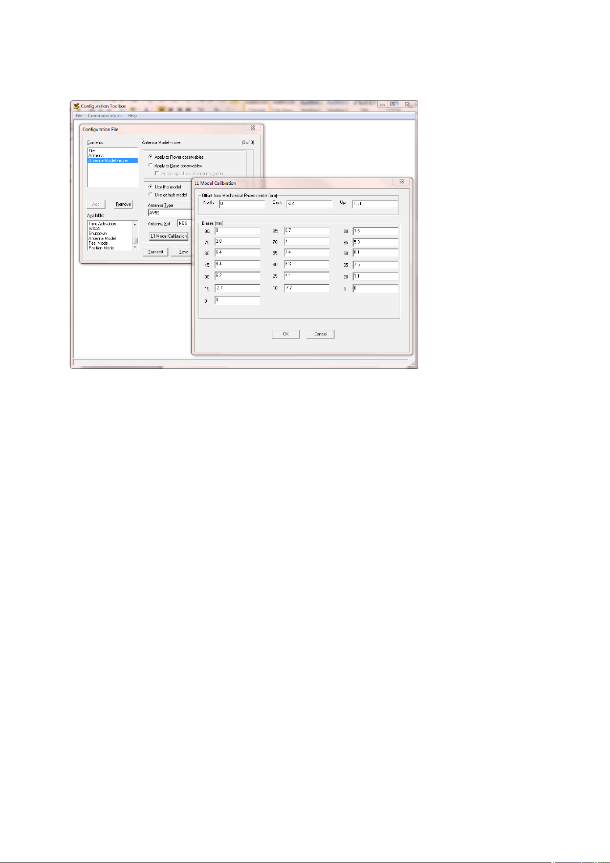
Antenna Phase Centers, Trimble recommends using the Configuration Toolbox software.
In the Configuration Toolbox software, you can add the Antenna page and then select the
antenna type:
If you select “Bottom of antenna mount” in the Method field, the True vertical height field
shows the distance between the Antenna Reference Point and the Mechanical Antenna
Phase Center.
If you want to understand the location of the L1 and L2 Antenna Phase Centers with
respect to the Mechanical Antenna Phase Center, add the Antenna Model page and then
select the antenna type. Click the L1 Model Calibration or L2 Model Calibration button to
view the offsets and the elevation-dependent tracking biases:
BD99x Series and BX992 GNSS Receiver ModuleUser Guide | 57
Page 58
5 GNSS andRTKBasics
These antenna calibrations are automatically used by the receiver when the correct
antenna type is selected. You only need to add the Antenna Model page if you want to
over-ride the antenna models. Trimble recommends using the default antenna models.
To download the most recent antenna models, go to
http://www.trimble.com/trimbleconfiguration_ts.asp.
BD99x Series and BX992 GNSS Receiver ModuleUser Guide | 58
Page 59

Quick Setup Guides
This section describes how to configure the receiver using the web interface and/or the
Binary TrimComm commands.
It comprises the following sections:
1. Configuring the receiver as a base station
2. Configuring the receiver as a rover
3. Configuring the receiver as a moving base
4. Setting up input/output on Ethernet ports:
l Using the AEh command to get the Ethernet configuration
l Using the AEh command to get the virtual IP ports
6
l Using the AEh command to get details on or set a virtual IP port
Related Sections:
l For a description of the web user interface, see the Receiver Web Interface, page 83.
l
For the Binary Interface Control Document, refer to the OEM GNSS Integrators Guide.
BD99x Series and BX992 GNSS Receiver ModuleUser Guide | 59
Page 60
Configuring the receiver as a base station
When setting up the base station, Trimble recommends the following steps:
1. Reset the unit to use the default application file:
6 QuickSetup Guides
2. Once the receiver is reset itself, the web page will update itself to show a message that
the reset is complete.
3. Set the Operation Mode field to Base and set the 1PPS On/Off field to Disable. Click OK
to save the settings:
BD99x Series and BX992 GNSS Receiver ModuleUser Guide | 60
Page 61
4. Set the Receiver Motion field to Static:
6 QuickSetup Guides
The 64h command to reset the receiver to defaults and put the unit into static mode is:
02 00 64 0A 00 00 00 03 00 01 01 0A 01 01 7F 03
Where:
RECORD BYTES: 0A 01 01
Decode as:
RECORD TYPE: 10 (0Ah (10) Static Kinematic)
RECORD LENGTH: 1
Static/Kinematic Mode: 1 (Static)
NOTE – The highlighted bit is set to 01 only in this command (since it resets the unit to defaults).
In the following steps this bit is set to 00 since a reset at that point would reset all of the settings
that have already been configured.
5. Set the CMR and RTCM ID values, station names and codes, and the reference position
of the base station:
NOTE – A warning message will pop up if the coordinates input into the fields is far away from
what the receiver is seeing.
BD99x Series and BX992 GNSS Receiver ModuleUser Guide | 61
Page 62

6 QuickSetup Guides
The 64h command to set these base parameters is:
02 00 64 62 00 00 00 03 00 01 00 03 59 00 00 42 41 53 45 20 20
20 20 3F E6 48 80 57 7F A2 1F BF FD 5A 5D DD 52 DF 68 40 9A 04
9C AC 08 31 27 00 02 01 40 41 42 41 53 45 20 20 20 20 20 20 20
20 20 20 20 20 20 20 20 20 42 74 65 73 74 5F 62 61 73 65 20 20
20 20 20 20 20 44 41 4E 4D 43 34 20 20 20 20 40 00 03 89 03
Where:
RECORD BYTES: 03 59 00 00 42 41 53 45 20 20 20 20 3F E6 48 80
57 7F A2 1F BF FD 5A 5D DD 52 DF 68 40 9A 04 9C AC 08 31 27 00
02 01 40 41 42 41 53 45 20 20 20 20 20 20 20 20 20 20 20 20 20
20 20 20 42 74 65 73 74 5F 62 61 73 65 20 20 20 20 20 20 20 44
41 4E 4D 43 34 20 20 20 20 40 00 03
Decode as:
RECORD TYPE: 3 (03h Reference Node)
RECORD LENGTH: 89
Flag (Reserved - set to 0x00): 0x00 (0)
Node Index (Reserved - set to 0x00): 0x00 (0)
Name: BASE
Reference Latitude (radians): 0.696350260635
Reference Longitude (radians): -1.834562172457
Reference Altitude (meters): 1665.1530
RTCM v2.x Station ID: 2
CMR Station ID: 1
BD99x Series and BX992 GNSS Receiver ModuleUser Guide | 62
Page 63

Frame Character (@): @
Station ID indicator: A
Station Point ID: BASE
Feature Code indicator: B
Feature Code: test_base
Epoch Rate indicator: D
Base quality indicator: A
Base point class indicator: N
Tracking indicator: 01001101
Antenna Type: 184
Flag (Reserved - set to 0x20): 0x20 (32)
Protocol Indicator (set to 0x20): 0x20 (32)
Flag (Reserved - set to 0x20): 0x20 (32)
Flag (Reserved - set to 0x20): 0x20 (32)
6 QuickSetup Guides
Frame Character (@): @
RTCM v3.x Station ID: 3
6. Set the antenna type, antenna height, and the measurement method:
The 64h command to set these base parameters is:
02 00 64 15 00 00 00 03 00 01 00 08 0C 40 00 AC A5 7A 00 00 00
00 B8 00 00 54 03
Where:
RECORD BYTES: 08 0C 40 00 AC A5 7A 00 00 00 00 B8 00 00
BD99x Series and BX992 GNSS Receiver ModuleUser Guide | 63
Page 64

6 QuickSetup Guides
Decode as:
RECORD TYPE: 8 (08h (8) Antenna)
RECORD LENGTH: 12
Antenna Height (meters): 2.0843
Antenna Type: 184
(Reserved - set to 0x00): 0
(Reserved - set to 0x00): 0
NOTE – In this example, because the bottom of antenna mount (the ARP) was selected, the
antenna height accounts for the distance between the antenna phase center (APC) and the ARP.
However, the output messages are always given for the position of the APC.
7. Configure the CMR or RTCM correction output. You can configure bandwidth limiting if
required:
The 64h command to set these base parameters is:
02 00 64 1B 00 00 00 03 00 01 00 02 04 01 05 00 00 07 0C 02 00
03 00 00 00 00 DC 00 00 00 00 83 03
Where:
RECORD BYTES: 02 04 01 05 00 00
Decode as:
RECORD TYPE: 2 (02h (2) Serial Port Baud Format)
RECORD LENGTH: 4
PORT INDEX (zero based): 1 (Serial port 2)
BAUD RATE: 5 (38.4K baud (default))
BD99x Series and BX992 GNSS Receiver ModuleUser Guide | 64
Page 65

6 QuickSetup Guides
PARITY: 0 (No Parity)
FLOW CONTROL: 0 (None)
Where:
RECORD BYTES: 07 0C 02 00 03 00 00 00 00 DC 00 00 00 00
Decode as:
RECORD TYPE: 7 (07h (7) Output Message)
RECORD LENGTH: 12
OUTPUT MESSAGE TYPE: 2 (CMR Output)
PORT INDEX (zero based): 0 (Serial port 1)
FREQUENCY: 3 (1 Hz)
OFFSET: 0
CMR Flag 1: 0 (CMR+)
CMR Flag 2: 0x00
BANDWIDTH LIMIT: 220
EXTRA BYTE1: 0x00
EXTRA BYTE2: 0x00
EXTRA BYTE3: 0x00
EXTRA BYTE4: 0x00
8. In the I/O Configuration / Port Summary page, verify that the CMR outputs are
configured. In this example, Serial1/COM1 shows CMR as its output.
BD99x Series and BX992 GNSS Receiver ModuleUser Guide | 65
Page 66

6 QuickSetup Guides
9. In the Receiver Status / Position page, verify that the base station is tracking satellites
and positioning:
BD99x Series and BX992 GNSS Receiver ModuleUser Guide | 66
Page 67

Configuring the receiver as a rover
When setting up a rover, Trimble recommends the following steps:
1. Reset the unit to use the default application file:
6 QuickSetup Guides
2. Set the Operation Mode to Rover:
BD99x Series and BX992 GNSS Receiver ModuleUser Guide | 67
Page 68

3. Set the RTK Motion to Kinematic:
6 QuickSetup Guides
The 64h command to reset the receiver to defaults and put the unit into a kinematic
mode is:
02 00 64 0A 00 00 00 03 00 01 01 0A 01 00 7E 03
Where:
RECORD BYTES: 0A 01 00
Decode as:
RECORD TYPE: 10 (0Ah (10) Static Kinematic)
RECORD LENGTH: 1
Static/Kinematic Mode: 0 (Kinematic)
NOTE – The highlighted bit is set to 01 only in this command (since it resets the unit to defaults).
In the following steps this bit is set to 00 since a reset at that point would reset all of the settings
that have already been configured.
BD99x Series and BX992 GNSS Receiver ModuleUser Guide | 68
Page 69

4. Set the antenna type, antenna height, and the measurement method:
6 QuickSetup Guides
The 64h command to set these base parameters is:
02 00 64 15 00 00 00 03 00 01 00 08 0C 3F B5 94 AF 40 00 00 00
00 B8 00 00 C0 03
Where:
RECORD BYTES: 3F B5 94 AF 40 00 00 00 00 B8 00 00
Decode as:
RECORD TYPE: 8 (08h (8) Antenna)
RECORD LENGTH: 12
Antenna Height (meters): 0.0843
Antenna Type: 184
(Reserved - set to 0x00): 0
(Reserved - set to 0x00): 0
NOTE – In this example, because the bottom of antenna mount (the ARP) was selected, the
antenna height accounts for the distance between the antenna phase center (APC) and the ARP.
However, the output messages are always given for the position of the APC.
BD99x Series and BX992 GNSS Receiver ModuleUser Guide | 69
Page 70
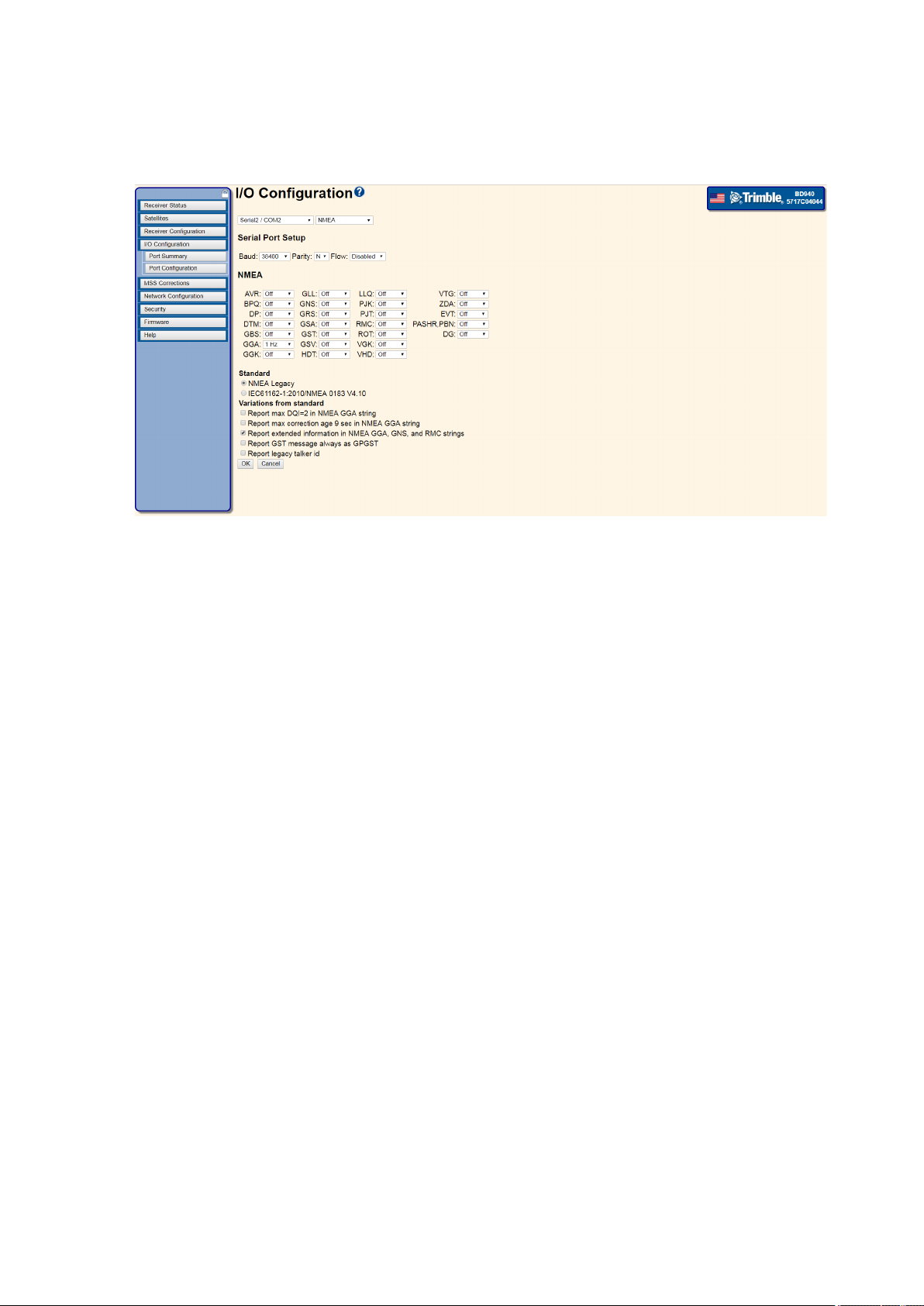
5. Configure any output messages:
6 QuickSetup Guides
The 64h command to set these base parameters is:
02 00 64 19 00 00 00 03 00 01 00 02 04 01 05 00 00 07 04 06 01
03 00 07 04 0D 01 03 00 BE 03
Where:
RECORD BYTES: 02 04 01 05 00 00
Decode as:
RECORD TYPE: 2 (02h (2) Serial Port Baud Format)
RECORD LENGTH: 4
PORT INDEX (zero based): 1 (Serial port 2)
BAUD RATE: 5 (38.4K baud (default))
PARITY: 0 (No Parity)
FLOW CONTROL: 0 (None)
Where:
RECORD BYTES: 07 04 06 01 03 00
Decode as:
RECORD TYPE: 7 (07h (7) Output Message)
RECORD LENGTH: 4
OUTPUT MESSAGE TYPE: 6 (NMEA_GGA)
PORT INDEX (zero based): 1 (Serial port 2)
FREQUENCY: 3 (1 Hz)
BD99x Series and BX992 GNSS Receiver ModuleUser Guide | 70
Page 71

6 QuickSetup Guides
OFFSET: 0
Where:
RECORD BYTES: 07 04 0D 01 03 00
Decode as:
RECORD TYPE: 7 (07h (7) Output Message)
RECORD LENGTH: 4
OUTPUT MESSAGE TYPE: 13 (NMEA_GST)
PORT INDEX (zero based): 1 (Serial port 2)
FREQUENCY: 3 (1 Hz)
OFFSET: 0
6. In the I/O Configuration / Port Summary page, verify that the CMR corrections are
inputs (if the text is bold then these corrections are being used in the position solution)
and verify the output messages:
BD99x Series and BX992 GNSS Receiver ModuleUser Guide | 71
Page 72

6 QuickSetup Guides
7. In the Receiver Status / Position page, verify that the rover is tracking satellites and
positioning using the input corrections from the base station:
BD99x Series and BX992 GNSS Receiver ModuleUser Guide | 72
Page 73

Configuring the receiver as a moving base
When setting up a moving base, Trimble recommends the following steps:
1. Reset the unit to use the default application file:
6 QuickSetup Guides
2. Set the Operation Mode to Moving Base:
BD99x Series and BX992 GNSS Receiver ModuleUser Guide | 73
Page 74

6 QuickSetup Guides
3. Set the RTK Motion to Kinematic and the RTK Mode field to Synchronous:
The 64h command to reset the receiver to defaults and put the unit into a kinematic
mode is:
02 00 64 14 00 00 00 03 00 01 01 0A 01 00 01 08 0A 02 63 00 00
00 00 00 00 03
Where:
RECORD BYTES: 0A 01 00
Decode as:
RECORD TYPE: 10 (0Ah (10) Static Kinematic)
RECORD LENGTH: 1
Static/Kinematic Mode: 0 (Kinematic)
Where:
RECORD BYTES: 01 08 0A 02 63 00 00 00 00 00
Decode as:
RECORD TYPE: 1 (01h (1) General Controls)
RECORD LENGTH: 9
Elevation Mask: 10
Meas Rate (OBSOLETE): 2 (10Hz)
PDOP Mask: 99
Frequency Source (RESERVED - set to 0x00): 0
Position Source (OBSOLETE - set to 0x00): 0
BD99x Series and BX992 GNSS Receiver ModuleUser Guide | 74
Page 75

6 QuickSetup Guides
RTK POSITIONING MODE: 0 (Synchronous positioning)
POSITIONING SOLUTION SELECTION: 0 (Use best available solution)
RESERVED - set to 0x00: 0
NOTE – The highlighted bit is set to 01 only in this command (since it resets the unit to defaults).
In the following steps this bit is set to 00 since a reset at that point would reset all of the settings
that have already been configured.
4. Set the antenna type, antenna height, and the measurement method:
The 64h command to set these base parameters is:
02 00 64 15 00 00 00 03 00 01 00 08 0C 3F B5 94 AF 40 00 00 00
00 B8 00 00 C0 03
Where:
RECORD BYTES: 3F B5 94 AF 40 00 00 00 00 B8 00 00
Decode as:
RECORD TYPE: 8 (08h (8) Antenna)
RECORD LENGTH: 12
Antenna Height (meters): 0.0843
Antenna Type: 184
(Reserved - set to 0x00): 0
(Reserved - set to 0x00): 0
NOTE – In this example, because the bottom of antenna mount (the ARP) was selected, the
antenna height accounts for the distance between the antenna phase center (APC) and the ARP.
However, the output messages are always given for the position of the APC.
BD99x Series and BX992 GNSS Receiver ModuleUser Guide | 75
Page 76
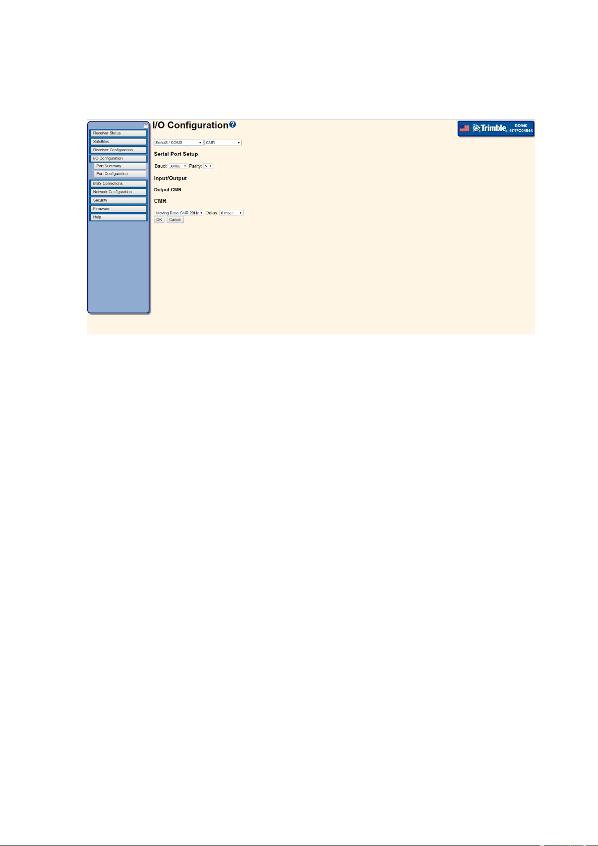
5. Configure the Moving Base CMR output:
6 QuickSetup Guides
The 64h command to set these base parameters is:
02 00 64 1B 00 00 00 03 00 01 00 02 04 02 05 00 00 07 0C 02 02
0D 00 01 00 00 00 00 00 00 00 B5 03
Where:
RECORD BYTES: 02 04 02 05 00 00
Decode as:
RECORD TYPE: 2 (02h (2) Serial Port Baud Format)
RECORD LENGTH: 4
PORT INDEX (zero based): 2 (Serial port 3)
BAUD RATE: 5 (38.4K baud (default))
PARITY: 0 (No Parity (10-bit format))
FLOW CONTROL: 0 (None)
Where:
RECORD BYTES: 07 0C 02 02 0D 00 01 00 00 00 00 00 00 00
Decode as:
RECORD TYPE: 7 (07h (7) Output Message)
RECORD LENGTH: 12
OUTPUT MESSAGE TYPE: 2 (CMR Output)
PORT INDEX (zero based): 2 (Serial port 3)
FREQUENCY: 13 (20 Hz)
BD99x Series and BX992 GNSS Receiver ModuleUser Guide | 76
Page 77

OFFSET: 0
CMR Flag 1: 1 (High speed CMR (5, 10, or 20 Hz))
CMR Flag 2: 00000000
BANDWIDTH LIMIT: 0
EXTRA BYTE1: 0x00 (0)
EXTRA BYTE2: 0x00 (0)
EXTRA BYTE3: 0x00 (0)
EXTRA BYTE4: 0x00 (0)
6. Configure any output messages:
6 QuickSetup Guides
The 64h command to set these base parameters is:
02 00 64 19 00 00 00 03 00 01 00 02 04 01 05 00 00 07 04 06 01
03 00 07 04 0D 01 03 00 BE 03
Where:
RECORD BYTES: 02 04 01 05 00 00
Decode as:
RECORD TYPE: 2 (02h (2) Serial Port Baud Format)
RECORD LENGTH: 4
PORT INDEX (zero based): 1 (Serial port 2)
BAUD RATE: 5 (38.4K baud (default))
PARITY: 0 (No Parity)
FLOW CONTROL: 0 (None)
BD99x Series and BX992 GNSS Receiver ModuleUser Guide | 77
Page 78

Where:
RECORD BYTES: 07 04 06 01 03 00
Decode as:
RECORD TYPE: 7 (07h (7) Output Message)
RECORD LENGTH: 4
OUTPUT MESSAGE TYPE: 6 (NMEA_GGA)
PORT INDEX (zero based): 1 (Serial port 2)
FREQUENCY: 3 (1 Hz)
OFFSET: 0
Where:
RECORD BYTES: 07 04 0D 01 03 00
Decode as:
RECORD TYPE: 7 (07h (7) Output Message)
6 QuickSetup Guides
RECORD LENGTH: 4
OUTPUT MESSAGE TYPE: 13 (NMEA_GST)
PORT INDEX (zero based): 1 (Serial port 2)
FREQUENCY: 3 (1 Hz)
OFFSET: 0
7. In the I/O Configuration / Port Summary page, verify that the CMR corrections are
inputs (if the text is bold then these corrections are being used in the position solution)
and verify the output messages:
BD99x Series and BX992 GNSS Receiver ModuleUser Guide | 78
Page 79

6 QuickSetup Guides
Setting up input/output on Ethernet ports
Configure the TCP or UDP ports to send data the same way as with the serial ports. When
configuring the TCP or UDP ports to receive data, they must be put into a client mode and
the source/server must be specified:
BD99x Series and BX992 GNSS Receiver ModuleUser Guide | 79
Page 80

6 QuickSetup Guides
Using the AEh command to get the Ethernet configuration
When working with the receivers using TrimComm commands, the IP address of the
receiver can be found by sending the AEh ETHERNET CFG subtype 00h command, for
example:
02 00 AE 01 00 AF 03
The receiver responds with the AEh ETHERNET CFG subtype 01h response, like this:
02 28 AE 16 01 00 0A 01 5E F2 FF FF FE 00 0A 01 5F FF 0A 01 5E 01
0A 01 50 18 8A 03
Which decodes as:
DHCP ACTIVE: 0
IP Address byte 1: 10
IP Address byte 2: 1
IP Address byte 3: 94
IP Address byte 4: 242
NETMASK byte 1: 255
NETMASK byte 2: 255
NETMASK byte 3: 254
NETMASK byte 4: 0
BROADCAST ADDRESS byte 1: 10
BROADCAST ADDRESS byte 2: 1
BROADCAST ADDRESS byte 3: 95
BROADCAST ADDRESS byte 4: 255
GATEWAY byte 1: 10
GATEWAY byte 2: 1
GATEWAY byte 3: 94
GATEWAY byte 4: 1
DNS SERVER ADDRESS byte 1: 10
DNS SERVER ADDRESS byte 2: 1
DNS SERVER ADDRESS byte 3: 80
DNS SERVER ADDRESS byte 4: 24
The AEh ETHERNET CFG subtype 02h command can be used to set these parameters.
BD99x Series and BX992 GNSS Receiver ModuleUser Guide | 80
Page 81

6 QuickSetup Guides
Using the AEh command to get the virtual IP ports
The receiver uses a “virtual port” for the IP ports which allows a single byte to identify the
port. To find the available virtual ports for the TCP and UDP ports on the IP stack, send the
AEh ETHERNET CFG subtype 0Ch command, for example:
02 00 AE 01 0C BB 03
The receiver responds with the AEh ETHERNET CFG subtype 0Dh response, like this:
02 E8 AE 08 0D 15 1E 04 15 16 17 18 3C 03
Which decodes as:
FIRST VIRTUAL PORT (1-based): 0x15 (21)
LAST VIRTUAL PORT (1-based): 0x1E (30)
No. ACTIVE VPORTS: 4
ACTIVE VPORTS (1-based): 0x15 (21)
ACTIVE VPORTS (1-based): 0x16 (22)
ACTIVE VPORTS (1-based): 0x17 (23)
ACTIVE VPORTS (1-based): 0x18 (24)
These are the port addresses that must be used in the 64h commands for sending output
messages from a TCP or UDP port.
BD99x Series and BX992 GNSS Receiver ModuleUser Guide | 81
Page 82

6 QuickSetup Guides
Using the AEh command to get details on or set a virtual IP port
To find details about a specific port, send the AEh ETHERNET CFG subtype 0Eh command,
for example (on port 16h):
02 00 AE 02 0E 16 D4 03
The receiver responds with the AEh ETHERNET CFG subtype 0Fh response, like this:
02 E8 AE 1F 0F 16 01 13 9A 00 3C 00 00 01 13 9B 00 00 00 00 00 00
00 0B 31 30 2E 31 2E 39 34 2E 32 33 35 A1 03
Which decodes as:
VIRTUAL PORT (1-based): 0x16 (22)
ACTIVE: 1
IP Port: 5018
Mode: 0
UDP TIMEOUT: 60
OUTPUT ONLY: 0
AUTHENTICATE: 0
INITIATE CONNECTION: 1
REMOTE IP PORT: 5019
AUTHENTICATION KEY:
REMOTE IP ADDR LENGTH: 11
REMOTE IP ADDRESS: 10.1.94.235
In this case you can see that the port is configured in a client mode, connected to
10.1.94.235. The AEh ETHERNET CFG subtype 10h command can be used to set these
parameters.
BD99x Series and BX992 GNSS Receiver ModuleUser Guide | 82
Page 83

7
Receiver Web Interface
This section of the user guide provides a detailed overview of the web interface.
l BD990
l BD992
l BX992
For BD992-INS and BX992 Inertial products, additional screens appear in the web interface
that enables configuration of the INS features. For details on the inertial portion of these
GNSS products, please see Reference Frames and Offset Measurements, page 1.
Receivers can also be configured using the Application File packets described in the Binary
Interface Control Document.
BD99x Series and BX992 GNSS Receiver ModuleUser Guide | 83
Page 84

Web interface menus
Use the web interface to configure the receiver settings.
Supported languages
The web interface is available in the following languages:
l English (en)
l Chinese (zh)
l Dutch (nl)
l Finnish (fi)
l French (fr)
l German (de)
l Italian (it)
7 Receiver Web Interface
l Japanese (ja)
l Norwegian (n)
l Polish (pl)
l Portuguese (pt)
l Russian (ru)
l Spanish (es)
l Swedish (sv)
Use the Receiver Configuration / Default Language setting to select the default language
for your use.
The web interface shows the configuration menus on the left of the browser window, and
the settings on the right. Each configuration menu contains related submenus to
configure the receiver and monitor receiver performance.
NOTE – The menus and options available depend on the type of receiver you have.
Supported browsers
For PCs and laptops, current versions of these HTML browsers are supported:
l Google Chrome (recommended)
l Mozilla Firefox
l Microsoft Internet Explorer for Windows operating systems
BD99x Series and BX992 GNSS Receiver ModuleUser Guide | 84
Page 85

7 Receiver Web Interface
l Opera
l Apple Safari
NOTE – Trimble seeks to support and operate properly with all web browsers, however no
guarantee can be made since Trimble does not develop these browsers. These browsers are
regularly updated by their developers, and the behavior of each browser is affected by the various
internal settings that can be customized by the user.
BD99x Series and BX992 GNSS Receiver ModuleUser Guide | 85
Page 86

Log in
7 Receiver Web Interface
BD99x Series and BX992 GNSS Receiver ModuleUser Guide | 86
Page 87

7 Receiver Web Interface
Log in
Enables you to log in to the receiver. Select the Log in field and when prompted enter a
username and password. To log out, return to this menu and click Log out.
The default username is admin.
The default password is password.
To the left of the screen you will see a blue bar with a list of menu options. This user guide
describes the function of each menu. At the top right of the blue menu bar you will see a
Lock symbol. Clicking on the lock screen enables you to hide the menu bar and enlarge the
information screen. The following figure shows the web page with the menu bar unlocked
and collapsed to the top left corner of the screen;
BD99x Series and BX992 GNSS Receiver ModuleUser Guide | 87
Page 88

7 Receiver Web Interface
To bring the menu bar back into view, click on the blue box in the top left corner. To
prevent the menu bar from hiding itself once the mouse pointer leaves its boundaries, click
on the lock icon to lock the menu bar in place.
BD99x Series and BX992 GNSS Receiver ModuleUser Guide | 88
Page 89

7 Receiver Web Interface
Receiver Status menu
The Receiver Status menu provides a quick link to review the receiver’s available options,
current firmware version, IP address, temperature, runtime, satellites tracked, current
outputs, available memory, position information, and more.
Receiver Status – Activity
This page lists information such as number of satellites tracked and available inputs and
outputs.
BD99x Series and BX992 GNSS Receiver ModuleUser Guide | 89
Page 90
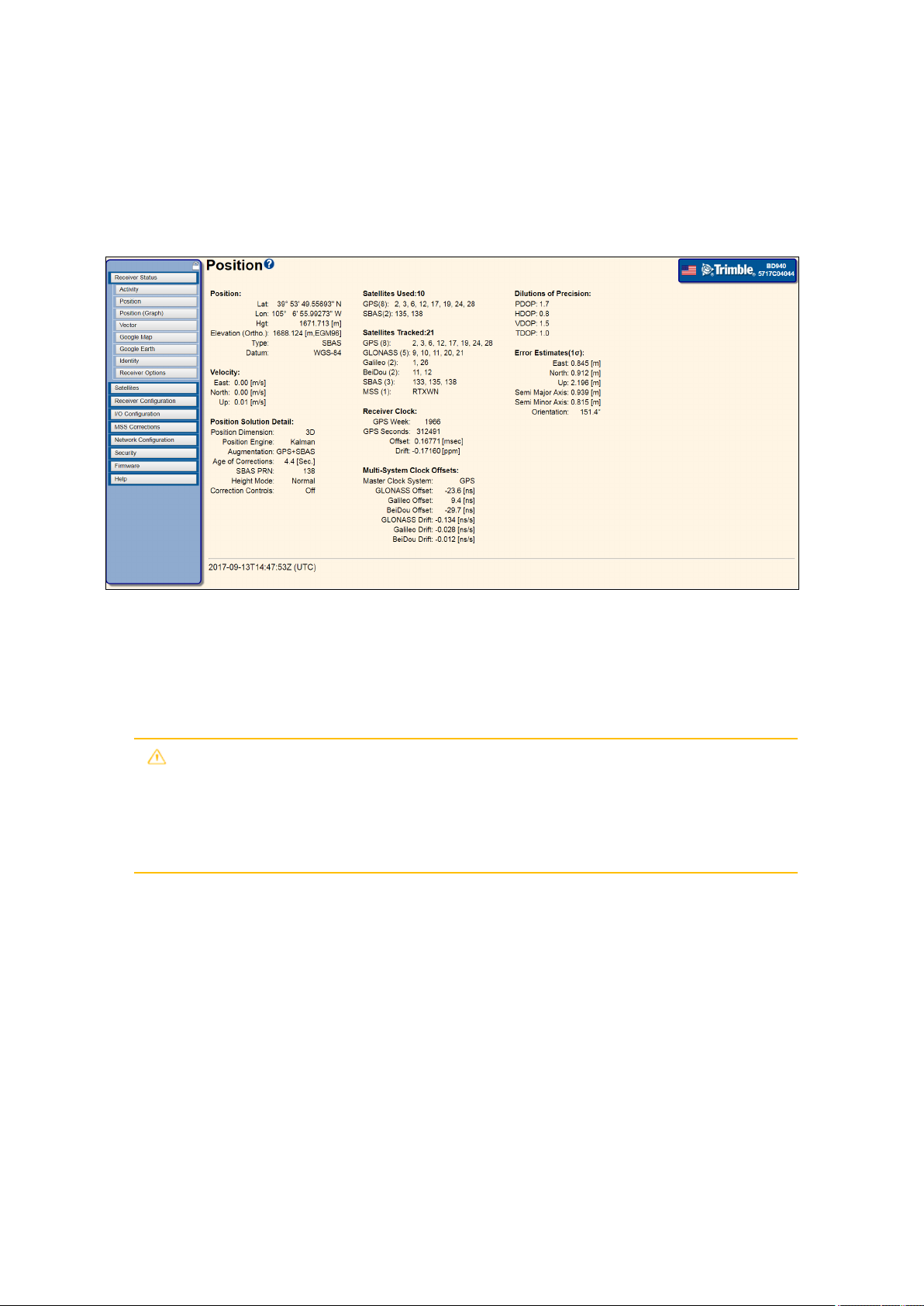
7 Receiver Web Interface
Position and Position Graph
This page shows information such as current coordinates of the receiver, elevation,
velocity, clock and other key GNSS information:
Position – Shows the current position solution.
l Lat – Latitude in degrees, minutes, and seconds.
l Lon – Longitude in degrees, minutes, and seconds.
l Hgt – Height above the ellipsoid to the Antenna Phase Center in meters.
CAUTION – The position output by the receiver is the Antenna Phase Center
position. You may want to reduce this position to a reference position elsewhere. If
so, you should account for any tilt of the antenna in such a reduction. The settings
for the Antenna Measurement Method and Antenna Height are not applied to this
output.
l Elevation (Ortho.) – xxx.xxx is annotated [m, EGM96] in meters. This field displays the
Orthometric height, Elevation, from the global EGM96 Geoid. If the receiver has a
coordinate system loaded, then
l the Elevation is annotated [m,SlopePln]
l or [m,Subgridname] where Subgridname is the first 8 characters of the uploaded
subgridded Geoid name.
l In all cases when a coordinate system is installed AND a subgrid is used AND the
Lat/Long position is outside the subgrid zone, then the receiver adds * to the
annotation like [m,name*] to warn the user.
BD99x Series and BX992 GNSS Receiver ModuleUser Guide | 90
Page 91

7 Receiver Web Interface
NOTE – From firmware version 4.70 onward, the global EGM96 geoid is the default geoid
in the receiver. The EGM96 geoid is a more precise estimation of the Mean Sea Level than
the older DMA geoid model in the receiver prior to version 4.70 firmware.
NOTE – From firmware version 4.70 and later, the global EGM96 geoid is the default geoid
in receivers with sufficient memory to store this geoid model. Receivers without sufficient
memory to store the EGM96 geoid will continue to use the DMA WGS-84 geoid. The EGM96
geoid is a more precise estimation of the Mean Sea Level than the older DMA WGS84 geoid
model.
l Type – Current position type.
l Old – No updated position available.
l Autonomous – Position has no satellite corrections applied.
l Code Diff – Code differential solution – typically a single-frequency solution.
l Phase Diff – Carrier phase differential solution (also known as Real-Time Kinematic
(RTK) solution), typically a dual-frequency solution.
l Beacon DGPS – Code phase differential solution using RTCM correction from an
internal IALA MSK beacon receiver.
l OmniSTAR VBS – Position using OmniSTAR VBS satellite-based correction service.
l OmniSTAR XP – Position using OmniSTAR XP satellite-based correction service.
l OmniSTAR HP – Position using OmniSTAR HP satellite-based correction service.
l OmniSTAR HP+G2 – Position using OmniSTAR HP and G2 satellite-based
correction service.
l CDGP – Position using the Canadian DGPS corrections.
l SBAS+ – Position using the SBAS Plus corrections.
l SBAS – Position using SBAS corrections.
l GVBS – Position using the clocks and orbits information from RTX corrections to
augment the autonomous solution.
l RTK and RTK Location – Carrier phase double difference position correction
service.
l RTX – Position using Trimble CenterPoint RTX satellite-based or IP correction
service.
l xFill – Position using Trimble xFill RTK augmentation service (5 minute duration
limit).
BD99x Series and BX992 GNSS Receiver ModuleUser Guide | 91
Page 92
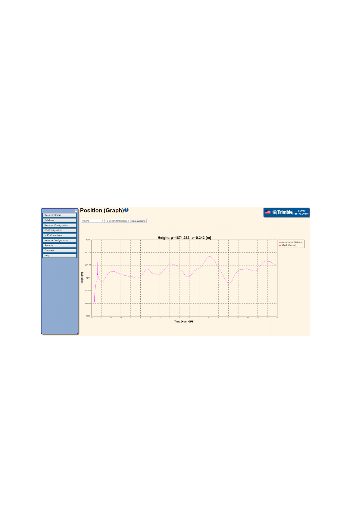
7 Receiver Web Interface
l xFill-RTX – Position using Trimble xFill RTK augmentation service with unlimited
duration. Service requires a CenterPoint RTX subscription.
l Precision – Displays the precision capability of the receiver.
l Datum – Displays the datum that the position is referenced to.
Position Graph
The Position Graph page lays out data such as height (in meters) against time (GPS hour).
This information is not restricted to just height but more graphs can be generated for data
sources such as PDOP/SVs, East, North, Horizontal, etc. To generate different graphs for
the available data sources, select a data source from the menus on the top left corner of
the Position Graph page.
To view this page correctly, you will need the latest Adobe Flash player installed and
enabled in your browser.
You can also switch between a ‘10 second position’ and also ‘high rate positions’.
l 10 Second Positions – The “10 Second” buffer contains data for up to the last 24 hours
at 10 second intervals. The graphs displayed update every 10 seconds as new data is
sent from the receiver to the browser.
l High Rate Positions – The “High Rate” buffer is 5,000 elements long and contains the
last 5,000 positions the receiver computed. The time-span depends on the position
rate of the receiver. Once the graph is drawn, data is sent from the receiver to the
browser at the position rate, so the graphs update in real time only, subject to network
and browser latencies.
NOTE – Both data source buffers are volatile. A reset of the graph is needed if the receiver is
restarted.
BD99x Series and BX992 GNSS Receiver ModuleUser Guide | 92
Page 93

7 Receiver Web Interface
Right-clicking on the graph also shows more options that enables you to manipulate the
graph. You can zoom in or out, print the graph or save it as a PNG file.
BD99x Series and BX992 GNSS Receiver ModuleUser Guide | 93
Page 94

7 Receiver Web Interface
Vector page
This page shows the RTK vector information. The RTK vector information is available only
when the Trimble receiver is receiving RTK corrections from a static or moving RTK base.
The vector information includes:
Vector – The RTK vector between the base and rover antennas. The RTK information is
only displayed if the receiver is receiving valid RTK correction data.
The following screen shows the information displayed when valid RTK correction data is
available to the receiver.
The following screen shows that there are no RTK corrections available:
BD99x Series and BX992 GNSS Receiver ModuleUser Guide | 94
Page 95

7 Receiver Web Interface
Google Map and Google Earth
This page shows the current position of the receiver plotted on Google Maps.
Refresh Interval – Sets the refresh rate of the map, which is useful if the receiver is moving
and you want to track its location. The refresh rate can be set to Off, 10 seconds, 20
seconds, 30 seconds, 1 minute, and 5 minutes.
The receiver also provides you with an option to export positional data to Google Earth. To
use this feature, you must have Google Earth 4.1 or later installed. To download Google
Earth, go to http://earth.google.com/download-earth.html. For more information, see
Google Earth, page 96.
BD99x Series and BX992 GNSS Receiver ModuleUser Guide | 95
Page 96

7 Receiver Web Interface
Google Earth
To use this feature, you must have Google Earth 4.1 or later installed. To download Google
Earth, go to http://earth.google.com/download-earth.html.
Use the Google Earth menu to open Google Earth through a link in the receiver. This sets
up a network link between the receiver and Google Earth. Google Earth shows the current
position of the receiver; this is refreshed every 30 seconds.
To open Google Earth, click and then click OK. When Google Earth opens, you will see a
placemarker showing the current position of the receiver.
NOTE – If you have security enabled, enter your username and password for the receiver's web
interface into the Google Earth login box.
Once the data has loaded into Google Earth, it should look similar to the following screen.
The point name shown is the serial number of the receiver:
Every 30 seconds, the position of the placemarker updates with the current position of the
receiver. Click the placemarker in Google Earth to view information about the current
position and the number of satellites tracked.
The receiver provides you with the option of sending up to approximately 200 bytes of
HTML to the placemarker (shown when you click the placemarker). This information must
be well-formed HTML and can be used to provide links to other web pages and/or an
image of the receiver.
NOTE – Version 4.10 of Google Earth does not allow you to use iframes. An example is shown of
what could be added to the HTML field in the receiver, where “myServer” is a web server:
<img width=“500” src='http://myServer/AntennaLocation.png'></img>
Then, when you click the placemarker it also downloads and shows
“AntennaLocation.png”, as shown in the following graphic. Approximately every 30 seconds
the placemarker disappears as Google Earth refreshes to show the receiver's position.
BD99x Series and BX992 GNSS Receiver ModuleUser Guide | 96
Page 97

7 Receiver Web Interface
Identity
This page shows information detailed information about the GNSS receiver such as IP
address, MAC address, and Firmware versions.
Some of the information shown is described in further detail below:
System Name – Provides a way to distinguish between receivers. In the System Name field
at the bottom of the screen, enter a logical name to identify the receiver such as "WorkSite
AlphaRxr". To help recognize the receiver when using the Zero Configuration service
discovery, enter a name that is clear and obvious. This name is visible when on a computer
that is on the same subnet as the receiver. Plan the assignment of system names,
especially in large networks, to help network administration.
Zeroconf/mDNS address – Shows the address used for the hardware when Zero
Configuration service discovery (mDNS/DNS-SD) is enabled and in use.
Firmware Version – Identifies the current software version running on the Trimble
receiver. Usually this will be the same as the Core Engine version unless some additional
functionality has been added that is independent of the core receiver operation.
Core Engine Version – Identifies the current core software running on the Trimble
receiver. This information is used to determine if more recent firmware is available from
Trimble, and also to identify the firmware if you need to contact Trimble Support. Receiver
firmware is loaded using the Install New Firmware menu.
Firmware Date – Identifies the date that the current software running on the Trimble
receiver was released.
RTK Version – Identifies the current version of the RTK engine. Used for troubleshooting
with technical support
BD99x Series and BX992 GNSS Receiver ModuleUser Guide | 97
Page 98

7 Receiver Web Interface
RTX Version – Identifies the current version of the RTX engine. Used for troubleshooting
with technical support.
Monitor Version – Identifies the current monitor version on the Trimble receiver.
Antenna Database Version – Identifies the current Antenna database version installed on
the Trimble receiver.
Hardware Version – Identifies the hardware version of the receiver.
BD99x Series and BX992 GNSS Receiver ModuleUser Guide | 98
Page 99

Receiver Options
This page shows which functionality the Trimble receiver has enabled.
7 Receiver Web Interface
Firmware Warranty Date – The date on which support for this receiver expires. Any
firmware that is dated earlier than this may be installed on the receiver. For firmware
patches, the Firmware Warranty Date may be earlier than the Firmware Date. To purchase
an extended warranty for the receiver, contact your local Trimble dealer.
Precision Capability – Defines the precision capabilities of the receiver in Base mode and
Rover mode.
l Not Activated – The receiver needs to be activated using an upgrade code. This is
usually completed by the Trimble Dealer or SITECH before delivery to the customer.
l Off – The receiver does not have this function installed. Ask your dealer if an upgrade is
available.
l Base – RTK – The base receiver can transmit CMR/RTCM corrections.
l Rover – Precise RTK – The rover receiver is capable of positioning at survey precisions
(sub-centimeter).
l Rover – Limited – The rover receiver is capable of positioning to the installed precision,
e.g., 10/10 indicates it can position to 10 cm (RMS) horizontal and 10 cm (RMS) vertical.
The actual precision depends on the correction source used.
Frequency
The total number of frequencies the receiver is capable of tracking. GNSS satellite
constellations are capable of transmitting at three frequencies.
Single Frequency Tracking – The receiver can track a single frequency.
BD99x Series and BX992 GNSS Receiver ModuleUser Guide | 99
Page 100

7 Receiver Web Interface
Dual Frequency Tracking – The receiver can track dual frequencies.
Triple Frequency Tracking – The receiver can track triple frequencies.
Constellation
Lists the GNSS satellite constellations tracking capability installed/enabled on the receiver.
Correction Services
Commercial GNSS augmentation services available for use on the receiver. Most of these
services require a paid subscription through Trimble Positioning Services.
l RTX – The receiver can track Trimble CenterPoint RTX correction services. A
CenterPoint RTX subscription is required to perform RTX surveying or to use unlimited
xFill services. The table displays the date of expiry of your subscription. A date in the
past represents there is not a valid subscription installed.
l xFill – When On, the receiver is capable of using the Trimble xFill RTK extension service.
l OmniSTAR HP/XP – The receiver can track OmniSTAR-HP and OmniSTAR-XP signals.
l OmniSTAR HP – The receiver can track the RTX, OmniSTAR-HP, OmniSTAR-XP, and
OmniSTAR VBS signals. To use RTX, the CMRx option must also be enabled via an RTK
Location 30/30 or higher upgrade.
l OmniSTAR VBS – The receiver can track OmniSTAR VBS signals.
Maximum Measurement Rate
The maximum rate at which observable data (measurements) can be logged.
Communication
The available wireless communications installed on the receiver.
l Bluetooth – The receiver can use Bluetooth wireless technology for communications.
l Internal Radio – The internal UHF or VHF radio is installed. Also shown is the current
radio bandwidth and country code.
l GSM/GPRS – The receiver can support a GSM/GPRS cellular modem.
l Wi-Fi – Indicates the receiver supports Wi-Fi in Access Point (AP) mode and Client
modes.
Additional Features
l Binary Outputs – Enables the receiver to output raw GPS and optional GLONASS data
in a Trimble proprietary format for use with datalogging.
BD99x Series and BX992 GNSS Receiver ModuleUser Guide | 100
 Loading...