

Page 1

USER GUIDE
Trimble BD970
GNSS Receiver Module
Version 5.11
Revision A
December 2015
1
Page 2

Corporate Office
Trimble Navigation Limited
Integrated Technologies
510 DeGuigne Drive
Sunnyvale, CA 94085
USA
www.trimble.com/gnss-inertial
Email: GNSSOEMSupport@trimble.com
Legal Notices
© 2006–2015, Trimble Navigation Limited. All rights reserved.
Trimble and the Globe & Triangle logo are trademarks of Trimble
Navigation Limited, registered in the United States and in other
countries. CMR+, EVEREST, Maxwell, and Zephyr are trademarks of
Trimble Navigation Limited.
Microsoft, Internet Explorer, Windows, and Windows Vista are either
registered trademarks or trademarks of Microsoft Corporation in the
United States and/or other countries.
All other trademarks are the property of their respective owners.
Support for Galileo is developed under a license of the European Union
and the European Space Agency
(BD910/BD920/BD930/BD935/BD970/BD982/BX935/BX982).
Release Notice
This is the December 2015 release (Revision A) of the BD970 GNSS
Receiver Module User Guide. It applies to version 5.11 of the receiver
firmware.
LIMITED W ARRANTY TERMS AND CONDITIONS
Product Limited Warranty
Subject to the following terms and conditions, Trimble Navigation
Limited (“Trimble”) warrants that for a period of one (1) year from date
of purchase unless otherwise specified, this Trimble product (the
“Product”) will substantially conform to Trimble's publicly available
specifications for the Product and that the hardware and any storage
media components of the Product will be substantially free from defects
in materials and workmanship.
Product Software
Product software, whether built into hardware circuitry as firmware,
provided as a standalone computer software product, embedded in flash
memory, or stored on magnetic or other media, is licensed solely for use
with or as an integral part of the Product and is not sold. If accompanied
by a separate end user license agreement (“EULA”), use of any such
software will be subject to the terms of such end user license agreement
(including any differing limited warranty terms, exclusions, and
limitations), which shall control over the terms and conditions set forth in
this limited warranty.
Software Fixes
During the limited warranty period you will be entitled to receive such
Fixes to the Product software that Trimble releases and makes
commercially available and for which it does not charge separately,
subject to the procedures for delivery to purchasers of Trimble products
generally. If you have purchased the Product from an authorized
Trimble dealer rather than from Trimble directly, Trimble may, at its
option, forward the software Fix to the Trimble dealer for final
distribution to you. Minor Updates, Major Upgrades, new products, or
substantially new software releases, as identified by Trimble, are
expressly excluded from this update process and limited warranty.
Receipt of software Fixes or other enhancements shall not serve to
extend the limited warranty period.
For purposes of this warranty the following definitions shall apply: (1)
“Fix(es)” means an error correction or other update created to fix a
previous software version that does not substantially conform to its
Trimble specifications; (2) “Minor Update” occurs when enhancements
are made to current features in a software program; and (3) “Major
Upgrade” occurs when significant new features are added to software,
or when a new product containing new features replaces the further
development of a current product line. Trimble reserves the right to
determine, in its sole discretion, what constitutes a Fix, Minor Update, or
Major Upgrade.
Warranty Remedies
If the Trimble Product fails during the warranty period for reasons
covered by this limited warranty and you notify Trimble of such failure
during the warranty period, Trimble will repair OR replace the
nonconforming Product with new, equivalent to new, or reconditioned
parts or Product, OR refund the Product purchase price paid by you, at
Trimble’s option, upon your return of the Product in accordance with
Trimble's product return procedures then in effect.
How to Obtain Warranty Service
To obtain warranty service for the Product, please contact your local
Trimble authorized dealer. Alternatively, you may contact Trimble to
request warranty service by e-mailing your request to
GNSSOEMSupport@trimble.com. Please be prepared to provide:
– your name, address, and telephone numbers
– proof of purchase
– a copy of this Trimble warranty
– a description of the nonconforming Product including the model
number
– an explanation of the problem
The customer service representative may need additional information
from you depending on the nature of the problem.
Warranty Exclusions or Disclaimer
This Product limited warranty shall only apply in the event and to the
extent that (a) the Product is properly and correctly installed, configured,
interfaced, maintained, stored, and operated in accordance with
Trimble's applicable operator's manual and specifications, and; (b) the
Product is not modified or misused. This Product limited warranty shall
not apply to, and Trimble shall not be responsible for, defects or
performance problems resulting from (i) the combination or utilization of
the Product with hardware or software products, information, data,
systems, interfaces, or devices not made, supplied, or specified by
Trimble; (ii) the operation of the Product under any specification other
than, or in addition to, Trimble's standard specifications for its products;
(iii) the unauthorized installation, modification, or use of the Product; (iv)
damage caused by: accident, lightning or other electrical discharge, fresh
or salt water immersion or spray (outside of Product specifications); or
exposure to environmental conditions for which the Product is not
intended; (v) normal wear and tear on consumable parts (e.g.,
batteries); or (vi) cosmetic damage. Trimble does not warrant or
guarantee the results obtained through the use of the Product, or that
software components will operate error free.
NOTICE REGARDING PRODUCTS EQUIPP ED WITH TECHNOLOGY C APABLE OF
TRACKING SATELLITE SIGNALS FROM SATELLITE BASED AUGMENTATION
SYSTEMS (SBAS) (WAAS/EGNOS, AND MSAS), OMNISTAR, GPS, MODERNIZED
GPS OR GLON ASS SATELLITES, OR FROM IALA B EACON SOURCES: TRIMBLE IS
NOT RESPON SIBLE FOR THE OPERATION OR FAILURE OF OPERATION OF ANY
SATELLITE BASED PO SITIONING SYSTEM OR THE AVAILABILITY OF ANY
SATELLITE BASED PO SITIONING SIGNALS.
THE FOREGOING LIMITED WARRANTY TERMS STATE TRIMBLE’S ENTIRE LIABILITY, AND
YOUR EXCLUSIVE REMEDIES, RELATING TO THE TRIMBLE PRODUCT. EXCEPT AS
OTHERWISE EXPRESSLY PROVIDED HEREIN, THE PRODUCT, AND ACCOMPANYING
DOCUMENTATION AND MATERIALS ARE PROVIDED “AS -IS” AND WITHOUT EXPRESS
OR IMPLIED WARRANTY OF ANY KIND, BY EITHER TRIMBLE OR ANYONE WHO HAS BEEN
INVOLVED IN ITS CREATION, PRODUCTION, INSTALLATION, OR DISTRIBUTION,
INCLUDING, BUT NOT LIMITED TO, THE IMPLIED WARRANTIES OF MERCHANTABILITY
AND FITNESS FOR A PARTICULAR PURPOSE, TITLE, AND NONINFRINGEMENT. THE
STATED EXPRESS WARRANTIES ARE IN LIEU OF ALL OBLIGATIONS OR LIABILITIES ON
THE PART OF TRIMBLE ARISING OUT OF, OR IN CONNECTION WITH, ANY PRODUCT.
BECAUSE SOME STATE S AND JURISDICTIONS DO NOT ALLOW LIMITATIONS ON
DURATION OR THE EXCLUSION OF AN IMPLIED WARRANTY, THE ABOVE LIMITATION
MAY NOT APPLY OR FULLY APPLY TO YOU.
Lim itation of Liability
TRIMBLE'S ENTIRE LIABILITY UNDER ANY PROVISION HEREIN SHALL BE LIMITED TO THE
AMOUNT PAID BY YOU FOR THE PRODUCT. TO THE MAXIMUM EXTENT PERMITTED BY
APPLICABLE LAW, IN NO EVENT SHA LL TRIMBLE OR ITS SUPPLIERS BE LIABLE FOR ANY
INDIRECT, SPECIAL, INCIDENTAL, OR CONSEQUENTIAL DAMAGE WHATSOEV ER UNDER
ANY CIRCUMSTA NCE OR LEGAL THEORY RELATING IN ANYWAY TO THE PRODUCTS,
SOFTWARE AND ACCOMPANYING DOCUMENTATION AND MATERIALS, (INCLUDING,
WITHOUT LIMITATION, DAMAGES FOR LOSS OF BUSINESS PROFITS, BUSINESS
INTERRUPTION, LOSS OF DATA, OR ANY OTHER PECUNIARY LOSS), REGARDLESS OF
WHETHER TRIMBLE HAS BEEN ADVISE D OF THE POSSIBILITY OF ANY SUCH LOSS AND
REGARDLESS OF THE COURSE OF DEALING WHICH DEVELOPS OR HAS DEV ELOPED
BETWEEN YOU AND TRIMBLE. BECAUSE SOME ST ATES AND JURISDICTIONS DO NOT
ALLOW THE EXCLUSION OR LIMITATION OF LIABILITY FOR CONSEQUENTIAL OR
INCIDENTAL DAMAGES, THE ABOVE LIMITATION MAY NOT APPLY OR FULLY APPLY TO
YOU.
BD970 GNSS Receiver Module User Guide 2
Page 3

PLEASE NOTE: THE ABOVE TRIMBLE LIMITED WARRANTY PRO VISIONS W ILL
NOT APPL Y TO P RODUCTS PURCHASED IN THOSE JU RISDICTIONS (E.G.,
MEMBER STATES OF THE EUROPEAN EC ONOMIC AREA) IN WHICH PR ODUCT
WARRANTIES ARE THE RESPONSIBILITY OF THE LOC AL TRIMBLE AUTHORIZED
DEALER FROM WHOM THE PRODUCTS ARE ACQUIRED. IN SUC H A CASE,
PLEASE CONTAC T YOUR LOC AL TRIMBLE AUTHORIZED DEALER FOR
APPL ICABLE WARRAN TY INFORMATION.
Official Language
THE OFFICIAL LANGUAGE OF THESE TERMS AND CONDITIONS IS ENGLISH. IN THE
EVENT OF A CONFLICT BETWEEN ENGLISH AND OTHER LANGUAGE VERSIONS, THE
ENGLISH LANGUAGE SHALL CONTROL.
COCOM limits
This notice applies to the BD910, BD920, BD920-W, BD920-W3G, BD930,
BD930-UHF, BD935-INS, BD960, BD970, BD982, BX960, BX960-2, and
BX982 receivers.
The U.S. Department of Commerce requires that all exportable GPS
products contain performance limitations so that they cannot be used in
a manner that could threaten the security of the United States. The
following limitations are implemented on this product:
– Immediate access to satellite measurements and navigation results is
disabled when the receiver velocity is computed to be greater than
1,000 knots, or its altitude is computed to be above 18,000 meters. The
receiver GPS subsystem resets until the COCOM situation clears. As a
result, all logging and stream configurations stop until the GPS
subsystem is cleared.
Restriction of Use of Certain Hazardous Substances in Electrical
and Electronic Equipment (RoHS)
Trimble products in this guide comply in all material respects with
DIRECTIVE 2002/95/EC OF THE EUROPEAN PARLIAMENT AND OF THE
COUNCIL of 27 January 2003 on the restriction of the use of certain
hazardous substances in electrical and electronic equipment (RoHS
Directive) and Amendment 2005/618/EC filed under C(2005) 3143, with
exemptions for lead in solder pursuant to Paragraph 7 of the Annex to
the RoHS Directive applied.
Waste Electrical and Electronic Equipment (WEEE)
For product recycling instructions and more information,
please go to
www.trimble.com/Corporate/Environmental_
Compliance.aspx.
Recycling in Europe: To recycle Trimble WEEE (Waste
Electrical and Electronic Equipment, products that run on
electrical power.), Call +31 497 53 24 30, and ask for the “WEEE
Associate”. Or, mail a request for recycling instructions to:
Trimble Europe BV
c/o Menlo Worldwide Logistics
Meerheide 45
5521 DZ Eersel, NL
BD970 GNSS Receiver Module User Guide 3
Page 4

Contents
Contents 4
1 Introduction 5
About the BD970 GNSS receiver 6
BD970 features 7
Default settings 9
Technical support 10
2 Specifications 11
Performance specifications 12
Physical specifications 13
Electrical specifications 13
Environmental specifications 14
Communication specifications 14
Receiver drawings 15
3 Electrical System Integration 16
BD970 receiver pinouts 17
1PPS and ASCII time tag 20
ASCII time tag 21
Power input 22
Antenna power output 22
LED control lines 23
Power switch and reset 24
Event 25
Serial port 26
USB 26
Ethernet 27
CAN 33
4 Installation 34
Unpacking and inspecting the shipment 35
Installation guidelines 35
Interface board evaluation kit 37
Routing and connecting the antenna cable 38
LED functionality and operation 40
5 Troubleshooting Receiver Issues 41
Glossary 43
BD970 GNSS Receiver Module User Guide 4
Page 5

Introduction
CHAPTER
1
n About the BD970 GNSS receiver
n BD970 features
n Default settings
n Technical support
This manual describes how to set up, configure,
and use the Trimble® BD970 GNSS receiver module.
The BD970 receiver uses advanced navigation
architecture to achieve real-time centimeter
accuracies with minimal latencies.
Even if you have used other GNSS or GPS products
before, Trimble recommends that you spend some
time reading this manual to learn about the special
features of this product. If you are not familiar with
GNSS or GPS, visit the Trimble website
(www.trimble.com).
BD970 GNSS Receiver Module User Guide 5
Page 6

1 Introduction
About the BD970 GNSS receiver
This receiver is used for a wide range of precise positioning and navigation applications. These uses
include unmanned vehicles and port and terminal equipment automation, and any other
application requiring reliable, centimeter-level positioning at a high update rate and low latency.
The receiver offers centimeter-level accuracy based on carrier phase RTK and submeter accuracy
code-based solutions.
Automatic initialization and switching between positioning modes allow for the best position
solutions possible. Low latency (less than 20 ms) and high update rates give the response time and
accuracy required for precise dynamic applications.
The receiver can be configured as an autonomous base station (sometimes called a reference
station) or as a rover receiver (sometimes called a mobile receiver). Streamed outputs from the
receiver provide detailed information, including the time, position, heading, quality assurance
(figure of merit) numbers, and the number of tracked satellites. The receiver also outputs a one
pulse-per-second (1 PPS) strobe signal which lets remote devices precisely synchronize time.
Designed for reliable operation in all environments, the receiver provides a positioning interface to
an office computer, external processing device, or control system. The receiver can be controlled
through a serial, ethernet, USB, or CAN port using binary interface commands or the web interface.
BD970 GNSS Receiver Module User Guide 6
Page 7

1 Introduction
BD970 features
The receiver has the following features:
l 220 Channels:
l l GPS: Simultaneous L1 C/A, L2E, L2C, L5
l GLONASS: Simultaneous L1 C/A, L1 P, L2 C/A (GLONASS M Only), L2 P
l SBAS: Simultaneous L1 C/A, L5
l GALILEO: Simultaneous L1 BOC, E5A, E5B, E5AltBOC
l BeiDou: Simultaneous B1, B2
l QZSS: Simultaneous L1 C/A, L1 SAIF, L2C, L5
l Advanced Trimble Maxwell Custom Survey GNSS Technology
l Very low noise GNSS carrier phase measurements with <1 mm precision in a 1 Hz bandwidth
l Proven Trimble low elevation tracking technology
l 1 USB port
l 1 CAN port
l 1 LAN Ethernet port
l Network Protocols supported
l l HTTP (web interface)
l NTP Server
l NMEA, GSOF, CMR over TCP/IP or UDP
l NTripCaster, NTripServer, NTripClient
l mDNS/UPnP Service discovery
l Dynamic DNS
l Email alerts
l Network link to Google Earth
l Support for external modems via PPP
l 3 x RS232 ports (baud rates up to 460,800)
l 1 Hz, 2 Hz, 5 Hz, 10 Hz, 20 & 50 Hz positioning outputs (depending on the installed option)
l Up to 50 Hz raw measurement and position outputs
l Correction inputs/outputs: CMR, CMR+™, sCMRx, RTCM 2.1, 2.2, 2.3, 2.4, 3.X, 3.2.
Note:
BD970 GNSS Receiver Module User Guide 7
Page 8

1 Introduction
l l The functionality to input or output any of these corrections depends on the installed
options.
l Different manufacturers may have established different packet structures for their
correction messages. Thus, the BD9xx receivers may not receive corrections from other
manufacturers' receivers, and other manufacturers' receivers may not be able to receive
corrections from BD9xx receivers.
l Navigation outputs:
l l ASCII: NMEA-0183: GBS; GGA; GLL; GNS; GRS; GSA; GST; GSV; HDT; LLQ; PTNL,AVR;
PTNL,BPQ; PFUGDP; DTM; PTNL,GGK; PTNL,PJK; PTNL,PJT; PTNL,VGK; PTNL,VHD; RMC;
ROT; VTG; ZDA
l Binary: Trimble GSOF
l Control Software
l 1 pulse-per-second (1PPS) output
l Event Marker Input support
l LED drive support
BD970 GNSS Receiver Module User Guide 8
Page 9

1 Introduction
Default settings
All settings are stored in application files. The default application file, Default.cfg, is stored
permanently in the receiver, and contains the factory default settings. Whenever the receiver is
reset to its factory defaults, the current settings (stored in the current application file, Current.cfg)
are reset to the values in the default application file.
These settings are defined in the default application file.
Function Settings Factory default
SV Enable - All SVs enabled
General Controls Elevation mask 10°
PDOP mask 99
RTK positioning mode Low Latency
Motion Kinematic
Ports Baud rate 38,400
Format 8-None-1
Flow control None
Input Setup Station Any
NMEA/ASCII (all supported messages) All ports Off
Streamed Output All types Off
Offset=00
RT17/Binary All ports Off
Reference Position Latitude 0°
Longitude 0°
Altitude 0.00 m HAE
Antenna Type Unknown
Height (true vertical) 0.00 m
Measurement method Antenna Phase Center
1PPS Disabled
BD970 GNSS Receiver Module User Guide 9
Page 10

1 Introduction
If a factory reset is performed, the above defaults are applied to the receiver. The receiver also
returns to a DHCP mode, and security is enabled (with a default login of admin and the password of
password). To perform a factory reset:
l From the web interface, select Receiver Configuration / Reset and then clear the Clear All
Receiver Settings option.
l Send the Command 58h with a 03h reset value.
Technical support
If you have a problem and cannot find the information you need in the product documentation,
send an email to GNSSOEMSupport@trimble.com.
Documentation, firmware, and software updates are available at:
www.intech.trimble.com/support/oem_gnss/receivers/trimble.
BD970 GNSS Receiver Module User Guide 10
Page 11

Specifications
CHAPTER
2
n Performance specifications
n Physical specifications
n Electrical specifications
n Environmental specifications
n Communication specifications
n Receiver drawings
This chapter details the specifications for the
receiver.
Specifications are subject to change without notice.
BD970 GNSS Receiver Module User Guide 11
Page 12

2 Specifications
Performance specifications
Feature Specification
Measurements
l Position antenna based on a 220-channel Maxwell 6 chip:
l l GPS: Simultaneous L1 C/A, L2E, L2C, L5
l GLONASS: Simultaneous L1 C/A, L1 P, L2 C/A (GLONASS M Only),
L2 P
l SBAS: Simultaneous L1 C/A, L5
l GALILEO: Simultaneous L1 BOC, E5A, E5B, E5AltBOC
l BeiDou: Simultaneous B1, B2
l QZSS: Simultaneous L1 C/A, L1 SAIF, L2C, L5
l
Advanced Trimble Maxwell 6 Custom Survey GNSS Technology
l
High precision multiple correlator for GNSS pseudorange
measurements
l
Unfiltered, unsmoothed pseudorange measurements data for low
noise, low multipath error, low time domain correlation and high
dynamic response
l
Very low noise GNSS carrier phase measurements with <1 mm
precision in a 1 Hz bandwidth
l
Signal-to-Noise ratios reported in dB-Hz
l
Proven Trimble low elevation tracking technology
Code differential
3D: Typically, < 1 m
GPS positioning
accuracy1
SBAS accuracy
2
Horizontal: Typically, < 1 m
Vertical: Typically, < 5 m
RTK positioning
accuracy
Horizontal: ±(8 mm + 1 ppm) RMS
Vertical: ±(15 mm + 1 ppm) RMS
(<30 km)
Initialization time Typically, less than 10 seconds
1
Accuracy and reliability may be subject to anomalies such as multipath, obstructions, satellite geometry, and atmospheric conditions. Always follow
recommended practices.
2
Depends on WAAS, EGNOS, and MSAS system performance.
BD970 GNSS Receiver Module User Guide 12
Page 13

2 Specifications
Feature Specification
Initialization
reliability
1
Typically >99.9%
Physical specifications
Feature Specification
Dimensions (L x W x H) 100 mm x 60 mm x 11.6 mm
Vibration MIL810F, tailored
Random 6.2 gRMS operating
Random 8 gRMS survival
Mechanical shock MIL810D
±40 g operating
±75 g survival
I/O connector 24-pin header + 6-pin header (Samtec TMM-120-03-L-D) (Rated for
1000 cycles)
Antenna connector MMCX receptacle (Huber-Suhner 82MMCX-50-0-1/111) (Rated for
500 cycles);
mating connectors are MMCX plug (Suhner 11MMCX-50-2-1C) or
right-angle plug (Suhner 16MMCX-50-2-1C, or 16MMCX-50-2-10)
Electrical specifications
Feature Specification
Voltage 3.3 V DC +5%/-3%
Power
consumption
Minimum
required
LNA gain
1
May be affected by atmospheric conditions, signal multipath, and satellite geometry. Initialization reliability is continuously monitored to ensure highest
quality.
Typically, 1.45 W (L1/L2 GPS)
Typically, 1.55 W (L1/L2 GPS and G1/G2 GLONASS)
Typically, 2.35 W (L1/L2/L5 GPS, G1/G2 GLONASS, B1/B2 BeiDou, L1/E5 Galileo)
Note –
These values were characterized using v4.84 firmware.
32.5 dB
Note –
a gain of 50 dB. Higher-gain antennas have not been tested.
This receiver is designed to operate with the Zephyr Model 2 antenna which has
BD970 GNSS Receiver Module User Guide 13
Page 14

2 Specifications
Environmental specifications
Feature Specification
Temperature Operating: -40°C to 75°C (-40°F to 167°F)
Storage: -55°C to 85°C (-67°F to 185°F)
Vibration MIL810F, tailored
Random 6.2 gRMS operating
Random 8 gRMS survival
Mechanical shock MIL810D
+/- 40 g operating
+/- 75 g survival
Operating humidity 5% to 95% R.H. non-condensing, at +60°C (140°F)
Communication specifications
Feature Specification
Communications 1 LAN port
3 x RS-232
ports
1 USB 2.0 port
Receiver position update rate 1 Hz, 2 Hz, 5 Hz, 10 Hz, 20 Hz and 50 Hz positioning
Correction data input CMR, CMR+™, sCMRx, RTCM 2.0–2.4, RTCM 3.X, 3.2
Correction data output CMR, CMR+, sCMRx, RTCM 2.0 DGPS (select RTCM 2.1), RTCM
2.1–2.4, RTCM 3.X, 3.2
Data outputs 1PPS, NMEA, Binary GSOF, ASCII Time Tags
l Supports links to 10BaseT/100BaseT
networks.
l All functions are performed through a single
IP address simultaneously – including web
interface access and data streaming.
Baud rates up to 460,800
BD970 GNSS Receiver Module User Guide 14
Page 15
2 Specifications
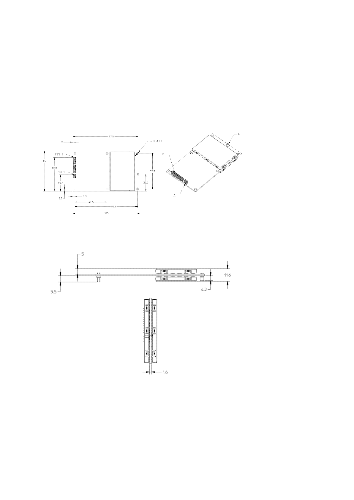
Receiver drawings
The following drawings show the dimensions of the BD970 receiver. Refer to these drawings if you
need to build mounting brackets and housings for the receiver.
Plan view
Edge view
BD970 GNSS Receiver Module User Guide 15
Page 16

Electrical System Integration
n BD970 receiver pinouts
n 1PPS and ASCII time tag
n ASCII time tag
n Power input
n Antenna power output
CHAPTER
3
n LED control lines
n Power switch and reset
n Event
n Serial port
n USB
n Ethernet
n CAN
BD970 GNSS Receiver Module User Guide 16
Page 17

3 Electrical System Integration
BD970 receiver pinouts
The receiver has a 24-pin and a 6-pin header side-by-side.
24-pin header
Pin Signal
name
1 GND Ground Digital ground Ground Digital ground
2 RTK LED RTK LED. Flashes when an RTK
3 POWER_
OFF
4 PPS
(Pulse
Per
Second)
5 VCC
Input DC
Card
Power
Description Integration notes
When used to drive an LED, a series
correction is present. This is similar
to all BD9xx products, except for the
requirement for an external resistor.
Powers the unit on and off. Drive high with a 3.3 V to turn off, leave
Pulse Per Second This is 3.3 V TTL level, 4mA max drive
VCC Input DC Card power (3.3 V
only)
resistor with a typical value of 300 Ohms is
required. This pin supplies a maximum
current of 4mA For LEDs with Vf above 2.7
or current excess of 4mA, an external
buffer is required.
floating or ground to keep the unit on.
Integrators should not drive TTL signals
when the unit is not powered.
capability. To drive 50 load to ground, an
external buffer is required.
VCC Input DC Card power (3.3 V only)
6 VCC
Input DC
Card
Power
7 Event2,
CAN1_Rx
and
COM3_
Rx
VCC Input DC Card power (3.3 V
only)
Event2 – Event input
CAN1_Rx - CAN Receive line
COM3_Rx – COM3 Receive line – TTL
Level
VCC Input DC Card power (3.3 V only)
MUTUALLY EXCLUSIVE and TTL level.
Connect Event2 to a TTL level signal to use
as Event.
Connect CAN1_Rx to RX line of a CAN
driver to use as CAN.
BD970 GNSS Receiver Module User Guide 17
Page 18

3 Electrical System Integration
Pin Signal
Description Integration notes
name
Connect COM3_Rx to a transceiver if RS-
232 level is required.
8 Event1 Event1 – Input Event1 (must be 3.3 V TTL level)
9 Power
LED
10 Satellite
LED
POWER Indicator. High when unit is
on, low when off. This is similar to all
BD9xx products, except for the
requirement for an external resistor.
This allows user to use this as a
control line.
Satellite LED. Rapid flash indicates
<5 satellites. Slow flash indicates >5
satellites.
When used to drive an LED, a series
resistor with a typical value of 300 Ohms is
required. This pin supplies a maximum
current of 4mA For LEDs with Vf above 2.7
or current excess of 4mA, an external
buffer is required.
When used to drive an LED, a series
resistor with a typical value of 300 Ohms is
required. This pin supplies a maximum
current of 4mA For LEDs with Vf above 2.7
or current excess of 4mA, an external
buffer is required.
11 COM2_
CTS
COM2 Clear to Send – TTL Level Connect COM2_CTS to a transceiver if RS-
232 level is required.
12 RESET_IN RESET_IN – ground to reset Drive low to reset the unit. Otherwise,
leave unconnected.
13 COM2_
RTS
COM 2 Request to Send – TTL Level Request to Send for COM 2 connect to a
transceiver if RS-232 level is required.
14 COM2_RxCOM 2 Receive Data – TTL Level Connect COM2_RX to a transceiver if RS-
232 level is required.
15 NO
Reserved
CONNECT
16 COM2_Tx COM 2 Transmit Data – TTL Level Connect COM2_TX to a transceiver if RS-
232 level is required
17 NO
Reserved
CONNECT
18 COM1_RxCOM 1 Receive Data – RS-232 Level
19 CAN1_Tx
and
COM3_Tx
CAN1_Tx - CAN Transmit line
COM3_Transmit Data – TTL Level
MUTUALLY EXCLUSIVE and TTL level.
Connect CAN1_Tx to TX line of a CAN
driver to use as CAN.
BD970 GNSS Receiver Module User Guide 18
Page 19

3 Electrical System Integration
Pin Signal
name
20 COM1_Tx COM 1 Transmit Data – RS-232 Level
21 USB D (-) USB D (-) Bi-directional USB interface
22 USB D (+) USB D (+) Bi-directional USB
23 GND Ground Digital ground Ground Digital ground
24 GND Ground Digital ground Ground Digital ground
Description Integration notes
Connect COM3_Tx to a transceiver if RS-
232 level is required
Device Mode only. If VCC is supplied, USB
data (-)
interface data (+)
detects VBUS.
Device Mode only. If VCC is supplied, USB
detects VBUS.
6-pin header
Pin Signal
name
Description Integration notes
1 ETH_RD- Ethernet Receive line minus. Differential
pair.
2 ETH_RD+ Ethernet Receive line plus. Differential
pair.
3 CENT_RD RD Magnetic center tap. Connect to Magnetics RD Center
4 ETH_TD+ Ethernet Transmit line plus. Differential
pair.
5 ETH_TD- Ethernet Transmit line minus. Differential
pair.
6 CENT_TD TD Magnetic center tap. Connect to Magnetics TD Center
Connect to Magnetics RD-.
Connect to Magnetics RD+.
Tap.
Connect to Magnetics TD+.
Connect to Magnetics TD-.
Tap.
BD970 GNSS Receiver Module User Guide 19
Page 20

3 Electrical System Integration
1PPS and ASCII time tag
The receiver can output a 1 pulse-per-second (1PPS) time strobe and an associated time tag
message. The time tags are output on a user-selected port.
The leading edge of the pulse coincides with the beginning of each UTC second. The pulse is driven
between nominal levels of 0.0 V and 3.3 V (see below). The leading edge is positive (rising from 0 V to
3.3 V). The receiver PPS out is a 3.3 V TTL level with a maximum source/sink current of 4 mA. If the
system requires a voltage level or current source/sink level beyond these levels, you must have an
external buffer. This line has ESD protection.
The illustration below shows the time tag relation to 1PPS wave form:
The pulse is about 8 microseconds wide, with rise and fall times of about 100 ns. Resolution is
approximately 40 ns, where the 40 ns resolution means that the PPS shifting mechanism in the
receiver can align the PPS to UTC/GPS time only within +/- 20 ns, but the following external factor
limits accuracy to approximately ±1 microsecond:
l
Antenna cable length
Each meter of cable adds a delay of about 2 ns to satellite signals, and a corresponding delay in
the 1PPS pulse.
BD970 GNSS Receiver Module User Guide 20
Page 21

3 Electrical System Integration
ASCII time tag
Each time tag is output about 0.5 second before the corresponding pulse. Time tags are in ASCII
format on a user-selected serial port. The format of a time tag is:
UTC yy.mm.dd hh:mm:ss ab
Where:
l UTC is fixed text.
l yy.mm.dd is the year, month, and date.
l hh:mm:ss is the hour (on a 24-hour clock), minute, and second. The time is in UTC, not GPS.
l a is an integer number representing the position-fix type:
1 = time solution only
2 = 1D position and time solution
3 = currently unused
4 = 2D position and time solution
5 = 3D position and time solution
l b is the number of GNSS satellites being tracked. If the receiver is tracking 9 or more satellites, b
will always be displayed as 9.
l Each time tag is terminated by a carriage return, line feed sequence. A typical printout looks
like:
UTC 02.12.21 20:21:16 56
UTC 02.12.21 20:21:17 56
UTC 02.12.21 20:21:18 56
Note – If the receiver is not tracking satellites, the time tag is based on the receiver clock. In this case, a and b
are represented by “??”. The time readings from the receiver clock are less accurate than time readings
determined from the satellite signals.
BD970 GNSS Receiver Module User Guide 21
Page 22

3 Electrical System Integration
Power input
Item Description
Power requirement The unit operates at 3.3 V +5%/-3%.
The 3.3 V should be able to supply 1 A of surge current. Worst-case full
load power consumption including antenna is 2.5 W.
The typical power consumption based on band usage is:
l Enable GPS only L1/L2/L5 = 1.6 W
l GPS + GLONASS = 1.7 W
l All bands enabled = 1.75 W
Power switch Pin 3 is an optional power-off pin. When driven high with 3.3V, the receiver
is powered off. This unit can be left floating or ground to keep the unit on.
System integrators should not drive TTL signals when unit is not powered..
Over-voltage
protection
Under-voltage
protection
Reverse voltage
protection
The absolute maximum voltage is 3.6 V.
The absolute minimum voltage is 3.2 V below nominal.
The unit is protected down to -3.6 V.
Antenna power output
Item Description
Power output
specification
Short-circuit
protection
The antenna supplies 100 mA at 5 V.
The unit has an over-current / short circuit protection. Short circuits may
cause the unit to reset.
BD970 GNSS Receiver Module User Guide 22
Page 23

3 Electrical System Integration
LED control lines
Item Description
Driving LEDs
Power LED This active-high line indicates that the unit is powered on.
Satellite LED
The outputs are 3.3V TTL level with a maximum source/sink current of
4mA. An external series resistor must be used to limit the current. The
value of the series resistor in Ohms is determined by:
(3.3-Vf)/(If) > Rs > (3.3 V - Vf)/(.004)
Rs = Series resistor
If = LED forward current, max typical If of the LED should be less than 3mA
Vf = LED forward voltage, max typical Vf of the LED should be less than
2.7V
Most LEDs can be driven directly as shown in the circuit below:
LEDs that do not meet If and Vf specification must be driven with a buffer
to ensure proper voltage level and source/sink current.
This active-high line indicates that the unit has acquired satellites.
A rapid flash indicates that the unit has less than 5 satellites acquired while
a slow flash indicates greater than 5 satellites acquired. This line will stay
on if the unit is in monitor mode.
RTK Correction A slow flash indicates that the unit is receiving corrections. This will also
flash when the unit is in monitor mode.
BD970 GNSS Receiver Module User Guide 23
Page 24

3 Electrical System Integration
Power switch and reset
Item Description
Power switch The integrator may choose to power on or power off the unit. If a 3.3 V
level signal is applied to pin 3, Power_Off pin, the unit will disconnect VCC.
The system integrator must ensure that other TTL level pins remain
unpowered when Power_Off is asserted. Powering TTL-level pins while the
unit is powered off will cause excessive leakage current to be sinked by
the unit.
The integrator may choose to always have the unit powered on. This is
accomplished by leaving the Power_Off pin floating or grounded.
Reset switch Driving Reset_IN_L, Pin 12, low will cause the unit to reset. The unit will
remain reset at least 140 mS after the Reset_In_L is deasserted. The unit
remains powered while in reset.
BD970 GNSS Receiver Module User Guide 24
Page 25

3 Electrical System Integration
Event
Item Description
Event 1 Pin 8 is dedicated as an Event_In pin.
This is a TTL only input; it is not buffered or protected for any inputs
outside of 0 V to 3.3 V. It does have ESD protection. If the system requires
event to handle a voltage outside this range, the system integrator must
condition the signal prior to connecting to the unit.
Event 2 Event 2 is multiplexed with COM3_RX and CAN_RX. The default setting is
to have this line set to COM3_RX. The Event 2 must be enabled in order
to use Event2.
When using the 63494 Development interface board, the user must not
connect anything to Port 3 and the CAN port when using Event 2. The
Com3 level selection switch is ignored when Event 2 is selected.
This is a TTL only input; it is not buffered or protected for any inputs
outside of 0 V to 3.3 V. It does have ESD protection. If the system requires
event to handle a voltage outside this range, the system integrator must
condition the signal prior to connecting to the unit.
Trimble recommends adding a Schmitt trigger and ESD protection to the Event_In pin. This prevents
any 'ringing' on the input from causing multiple and incorrect events to be recognized.
For more information, go to www.trimble.com/OEM_ReceiverHelp/V5.11/default.html#AppNote_
EventInput.html.
BD970 GNSS Receiver Module User Guide 25
Page 26

3 Electrical System Integration
Serial port
Item Description
COM 1 RS-232 level
no flow control
COM 2 TTL level with
flow control
COM 3 TTL level no
flow control
COM 1 is already at RS-232 level and already has 8 kV contact discharge/15
kV air gap discharge ESD Protection. This is labeled Port 1 on the I/O
board.
COM 2 is at 0-3.3 V TTL. This port has RTS/CTS to support hardware flow
control. If the integrator needs this port to be at RS-232 level, a proper
transceiver powered by the same 3.3V that powers the receiver needs to
be added.
For development using the I/O board, this COM port is already connected
to an RS-232 transceiver. This is labeled Port 2 on the I/O board.
COM 3 is at 0-3.3 V TTL and is multiplexed with CAN. The receive line is also
multiplexed with Event 2. The integrator must have a BD982 receiver
configured to use the serial port in order to use this port as a serial port.
The functionality cannot be multiplexed in real time. If the integrator
needs this port to be at RS-232 level, a proper transceiver powered by the
same 3.3 V that powers the receiver needs to be added.
For development using the I/O board, this com port is already connected
to an RS-232 transceiver. This is labeled Port 3 on the I/O board. SW4,
labeled COM3 HW Xciever Selection, must be set to RS-232. There should
not be anything connected to TP5, labeled Event 2.
USB
The USB has a built-in PHY. The unit supports USB 2.0 Device configuration at low speed, full speed
and high speed configuration. The port has ESD protection; however a USB 2.0 compliant common
mode choke located near the connector should be added to ensure EMI compliance.
BD970 GNSS Receiver Module User Guide 26
Page 27

3 Electrical System Integration
Ethernet
The receiver contains the Ethernet MAC and PHY, but requires external magnetics. The PHY layer is
based on the Micrel KSZ8041NLI it is set to default to 100Mbps, full duplex with auto-negotiation
enabled. The receiver has the proper PHY termination on the differential signals as well as Bulk
capacitance for the magnetics center tap.
Isolation transformer selection
Parameters Value Test condition
Turns Ratio 1CT:1CT
Open-circuit inductance (min.) 350 uH 100 mV, 100 kHz, 8 mA
Leakage inductance (max.) 0.4 uH 1 MHz (min.)
DC resistance (max.) 0.9 Ohms
Insertion loss (max.) 1.0 dB 0 MHz–65 MHz
HiPot (min. 1500 Vrms
Ethernet reference design
The Ethernet interface can be implemented using a single part or using discrete components. For
more information, see:
l Ethernet design using RJ-45 with integrated magnetics, page 28
l Ethernet design using discrete components, page 29
BD970 GNSS Receiver Module User Guide 27
Page 28

3 Electrical System Integration
Ethernet design using RJ-45 with integrated magnetics
The Ethernet interface can be implemented with a single part by using an integrated part like TE
Connectivity’s 6605767-1 which has magnetics, common mode choke, termination and transient
voltage suppression fully integrated in one part.
RJ-45 drawing
JX10-0006NL schematic
BD970 GNSS Receiver Module User Guide 28
Page 29

3 Electrical System Integration
Electrical characteristics
Parameter Specifications
Insertion loss 100 kHz 1-125 MHz
-1.2 dB max. -0.2–0.002*f
Return loss
(Z out = 100 Ohm +/- 15%)
Inductance (OCL)
(Media side -40°C + 85°C)
Crosstalk, adjacent channels 1 MHz 10-100 MHz
Common mode rejection radio 2 MHz 30–200 MHz
DC resistance
1/2 winding
DC resistance
imbalance
input - output
isolation
0.1–30 MHz:
30–60 MHz:
60–80 MHz:
350 uH min. Measured at 100 kHz, 100 mVRMS and with 8
-50 dB min. -50+17*LOG10(f/10) dB min.
-50 dB min. -15+20*LOG10 (f/200) dB min.
0.6 Ohms max.
+/- 0.065 Ohms max. (center tap symmetry)
1500 Vrms min. at 60 seconds
-16 dB min.
-10+20*LOG
(f/60 MHz dB min.)
-10 dB min.
mA DC bias)
^1.4 db max.
10
Ethernet design using discrete components
For maximum flexibility, a system integrator may choose to implement the Ethernet using discrete
parts. The design below shows an example of such a design. It includes the Ethernet magnetics,
termination of unused lines as well as surge protection. The magnetics used is a Pulse Engineering
HX1188. Surge protection is provided by a Semtech SLVU2.8-4. In order to meet electrical isolation
requirements, it is recommended to use capacitors with a greater than 2 kV breakdown voltage.
BD970 GNSS Receiver Module User Guide 29
Page 30

3 Electrical System Integration
Ethernet schematic
Part Reference Value
C3 1000pF 2 kV
C4 1000pF 2 kV
C5 1000pF 2 kV
D7 SEMTECH SLVU2.8–4
J2 Main Conn
J5 RJ45 Conn
L300 Fer. Bead 300 mA 1 k @ 1 MHz
L301 Fer. Bead 300 mA 1 k @ 1 MHz
R11 49.9 0402 1%
R13 49.9 0402 1%
R15 49.9 0402 1%
R16 49.9 0402 1%
R17 49.9 0402 1%
BD970 GNSS Receiver Module User Guide 30
Page 31

3 Electrical System Integration
Part Reference Value
R23 49.9 0402 1%
R24 49.9 0402 1%
R25 49.9 0402 1%
T1 Pulse engineering HX1188
Ethernet routing
The distance from J11, the Ethernet connector and the magnetics should be less than 2 inches. The
distance from the RJ-45 and the magnetics should be minimized to prevent conducted emissions
issues. In this design, the chassis ground and signal ground are separated to improve radiated
emissions. The integrator may choose to combine the ground. The application note from the IC
vendor is provided below for more detailed routing guidelines.
The sample routing below shows a two-layer stack up, with single side board placement. The routing
shown below makes sure that the differential pairs are routed over solid planes.
Top view
BD970 GNSS Receiver Module User Guide 31
Page 32

3 Electrical System Integration
Bottom view
BD970 GNSS Receiver Module User Guide 32
Page 33

3 Electrical System Integration
CAN
COM 3 is at 0-3.3 V TTL and is multiplexed with CAN. The receive line is also multiplexed with Event 2.
The integrator must have a receiver configured to use the CAN port in order to use this port as a
serial port. The functionality cannot be multiplexed in real time. The integrator must add a CAN
transceiver in order to use the CAN Port.
For development using the I/O board, this com port is already connected to a CAN transceiver. This
is labeled CAN on the I/O board. SW4, labeled COM3 HW Xciever Selection, must be set to CAN.
There shouldn't be anything connected to TP5, labeled Event 2.
The following figure shows a typical implementation with a 3.3 V CAN transceiver. It also shows a
common mode choke as well as ESD protection. A 5 V CAN Transceiver can be used if proper level
translation is added.
BD970 GNSS Receiver Module User Guide 33
Page 34

Installation
CHAPTER
4
n Unpacking and inspecting the shipment
n Installation guidelines
n Interface board evaluation kit
n Routing and connecting the antenna cable
n LED functionality and operation
BD970 GNSS Receiver Module User Guide 34
Page 35

4 Installation
Unpacking and inspecting the shipment
Visually inspect the shipping cartons for any signs of damage or mishandling before unpacking the
receiver. Immediately report any damage to the shipping carrier.
Shipment carton contents
The shipment will include one or more cartons depending on the number of optional accessories
ordered. Open the shipping cartons and make sure that all of the components indicated on the bill
of lading are present.
Reporting shipping problems
Report any problems discovered after you unpack the shipping cartons to both Trimble Customer
Support and the shipping carrier.
Installation guidelines
The receiver is designed to be standoff mounted. You must use the appropriate hardware and all of
the mounting holes. Otherwise, you violate the receiver hardware warranty. For more information,
refer to the drawings of the receiver.
Considering environmental conditions
Install the receiver in a location situated in a dry environment. Avoid exposure to extreme
environmental conditions. This includes:
l Water or excessive moisture
l Excessive heat greater than 75 °C (167 °F)
l Excessive cold less than –40 °C (–40 °F)
l Corrosive fluids and gases
Avoiding these conditions improves the receiver’s performance and long-term product reliability.
Supported antennas
The receiver tracks multiple GNSS frequencies; the Trimble Zephyr™ II antenna supports these
frequencies.
Other antennas may be used with the receiver. However, ensure that the antenna you choose
supports the frequencies you need to track.
BD970 GNSS Receiver Module User Guide 35
Page 36

4 Installation
For the BD970 receiver, the antenna must operate at 5 V with a greater than 32.5 dB signal at the
board antenna port.
Mounting the antennas
Choosing the correct location for the antenna is critical for a high quality installation. Poor or
incorrect placement of the antenna can influence accuracy and reliability and may result in damage
during normal operation. Follow these guidelines to select the antenna location:
l If the application is mobile, place the antenna on a flat surface along the centerline of the
vehicle.
l Choose an area with clear view to the sky above metallic objects.
l Avoid areas with high vibration, excessive heat, electrical interference, and strong magnetic
fields.
l Avoid mounting the antenna close to stays, electrical cables, metal masts, and other antennas.
l Avoid mounting the antenna near transmitting antennas, radar arrays, or satellite
communication equipment.
Sources of electrical interference
Avoid the following sources of electrical and magnetic noise:
l Gasoline engines (spark plugs)
l Television and computer monitors
l Alternators and generators
l Electric motors
l Propeller shafts
l Equipment with DC-to-AC converters
l Fluorescent lights
l Switching power supplies
BD970 GNSS Receiver Module User Guide 36
Page 37

4 Installation
Interface board evaluation kit
An evaluation kit is available for testing the receiver. It includes an I/O board that gives access to:
l Power input connector
l Power ON/OFF switch
l Three serial ports through DB9 connectors
l
Ethernet through an RJ45 connector
Note – There are separate Ethernet jacks for the BD960/BD982 and BD970 boards.
l USB port through USB Type B receptacle
l CAN port through a DB9 connector
l Two event input pins
l 1PPS output on BNC connector
l
CAN / Serial port 3 switch
Note – To switch between serial port 3 and CAN, you must configure the receiver using the web
interface or binary commands. If you do not set an option bit to make CAN the default, the receiver
defaults to serial.
l Three LEDs to indicate satellite tracking, receipt of corrections, and power
The following figure shows a typical I/O board setup:
❶ BD970 receiver ❷ I/O board ❸ Zephyr antenna
BD970 GNSS Receiver Module User Guide 37
Page 38

4 Installation
The computer connection provides a means to set up and configure the receiver.
Current or prospective customers may obtain schematic drawings of the evaluation I/O board by
contacting GNSSOEMSupport@trimble.com.
Routing and connecting the antenna cable
1.
After mounting the antenna, route the antenna cable from the GPS antenna to the receiver.
Avoid the following hazards when routing the antenna cable:
l l Sharp ends or kinks in the cable
l Hot surfaces (such as exhaust manifolds or stacks)
l Rotating or reciprocating equipment
l Sharp or abrasive surfaces
l Door and window jams
l Corrosive fluids or gases
2.
After routing the cable, connect it to the receiver. Use tie-wraps to secure the cable at several
points along the route. For example, to provide strain relief for the antenna cable connection,
use a tie-wrap to secure the cable near the base of the antenna.
Note – When securing the cable, start at the antenna and work towards the receiver.
3. When the cable is secured, coil any slack. Secure the coil with a tie-wrap and tuck it in a safe
place.
BD970 GNSS Receiver Module User Guide 38
Page 39

4 Installation
❶ BD970 GNSS
❷ MMCX connector ❸ GNSS antenna
receiver
Note – The MMCX connector at the end of antenna cable needs a CBL ASSY TNCMMCX connector to interface with the receiver module.
BD970 GNSS Receiver Module User Guide 39
Page 40

4 Installation
LED functionality and operation
The evaluation interface board comes with three LEDs to indicate satellite tracking, RTK receptions,
and power. The initial boot-up sequence for a receiver lights all the three LEDs for about three
seconds followed by a brief duration where all three LEDs are off. Thereafter, use the following table
to confirm tracking of satellite signals or for basic troubleshooting.
For single antenna configurations, the following LED patterns apply:
Power LED RTK
Corrections
LED
On
(continuous)
On
(continuous)
On
(continuous)
On
(continuous)
On
(continuous)
On
(continuous)
On
(continuous)
Off Off The receiver is turned on, but not tracking
Off Blinking at
Blinking at 1 Hz Blinking at
Off or blinking
(receiving
corrections)
Blinking at 1 Hz Off The receiver is receiving incoming RTK
Blinking at 5 Hz Blinking at
On
(continuous)
SV Tracking
LED
1 Hz
1 Hz
Blinking at 5
Hz for a short
while
1 Hz
Blinking at 1 HzThe receiver is receiving Moving Base RTK
Status
satellites.
The receiver is tracking satellites, but no
incoming RTK corrections are being received.
The receiver is tracking satellites and receiving
incoming RTK corrections.
Occurs after a power boot sequence when the
receiver is tracking less than 5 satellites and
searching for more satellites.
corrections, but not tracking satellites.
The receiver is receiving Moving Base RTK
corrections at 5 Hz.
corrections at 10 or 20 Hz (the RTK LED turns off
for 100 ms if a correction is lost).
On
(continuous)
On
(continuous)
On, blinking
off briefly at 1
Hz
Blinking at 1 Hz On
Blinking at 1 HzThe receiver is in a base station mode, tracking
(continuous)
satellites and transmitting RTK corrections.
The receiver is in Boot Monitor Mode. Use the
WinFlash utility to reload application firmware
onto the board. For more information, contact
technical support.
BD970 GNSS Receiver Module User Guide 40
Page 41

CHAPTER
5
Troubleshooting Receiver Issues
This section describes some possible receiver issues, possible causes, and how to solve them. Please read
this section before you contact Technical Support.
Issue Possible cause Solution
The receiver does
not turn on.
The base station
receiver is not
broadcasting.
Rover receiver is
not receiving
radio.
External power is too low. Check that the input voltage is within limits.
Port settings between
reference receiver and
radio are incorrect.
Faulty cable between
receiver and radio.
No power to radio. If the radio has its own power supply, check the
The base station receiver
is not broadcasting.
Incorrect over air baud
rates between reference
and rover.
Check the settings on the radio and the receiver.
Try a different cable.
Examine the ports for missing pins.
Use a multimeter to check pinouts.
charge and connections.
Examine the ports for missing pins.
Use a multimeter to check pinouts.
See the issue "The base station receiver is not
broadcasting" above.
Connect to the rover receiver radio, and make
sure that it has the same setting as the reference
receiver.
Incorrect port settings
between roving external
radio and receiver.
The receiver is The GPS antenna cable is Make sure that the GPS antenna cable is tightly
If the radio is receiving data and the receiver is
not getting radio communications, check that the
port settings are correct.
BD970 GNSS Receiver Module User Guide 41
Page 42

5 Troubleshooting Receiver Issues
Issue Possible cause Solution
not receiving
satellite signals.
loose. seated in the GPS antenna connection on the
GPS antenna.
The cable is damaged. Check the cable for any signs of damage. A
damaged cable can inhibit signal detection from
the antenna at the receiver.
The GPS antenna is not in
clear line of sight to the
Make sure that the GPS antenna is located with a
clear view of the sky.
sky.
Restart the receiver as a last resort (turn off and
then turn it on again).
BD970 GNSS Receiver Module User Guide 42
Page 43

Glossary
1PPS
almanac
base station
BeiDou
Pulse-per-second. Used in hardware timing. A pulse is generated in
conjunction with a time stamp. This defines the instant when the time
stamp is applicable.
A file that contains orbit information on all the satellites, clock
corrections, and atmospheric delay parameters. The almanac is
transmitted by a GNSS satellite to a GNSS receiver, where it facilitates
rapid acquisition of GNSS signals when you start collecting data, or
when you have lost track of satellites and are trying to regain GNSS
signals.
The orbit information is a subset of the ephemeris/ephemerides data.
Also called reference station. In construction, a base station is a
receiver placed at a known point on a jobsite that tracks the same
satellites as an RTK rover, and provides a real-time differential
correction message stream through radio to the rover, to obtain
centimeter level positions on a continuous real-time basis. A base
station can also be a part of a virtual reference station network, or a
location at which GNSS observations are collected over a period of
time, for subsequent postprocessing to obtain the most accurate
position for the location.
The BeiDou Navigation Satellite System (also known as BDS ) is a
Chinese satellite navigation system.
The first BeiDou system (known as BeiDou-1), consists of four satellites
and has limited coverage and applications. It has been offering
navigation services mainly for customers in China and from
neighboring regions since 2000.
The second generation of the system (known as BeiDou-2) consists of
satellites in a combination of geostationary, inclined geosynchronous,
and medium earth orbit configurations. It became operational with
coverage of China in December 2011. However, the complete Interface
Control Document (which specifies the satellite messages) was not
released until December 2012. BeiDou-2 is a regional navigation service
which offers services to customers in the Asia-Pacific region.
A third generation of the BeiDou system is planned, which will expand
coverage globally. This generation is currently scheduled to be
completed by 2020.
BINEX
BInary EXchange format. BINEX is an operational binary format
standard for GPS/GLONASS/SBAS research purposes. It is designed to
grow and allow encapsulation of all (or most) of the information
currently allowed for in a range of other formats.
BD970 GNSS Receiver Module User Guide 43
Page 44

Glossary
broadcast server
carrier
carrier frequency
carrier phase
cellular modems
CMR/CMR+
CMRx
An Internet server that manages authentication and password control
for a network of VRS servers, and relays VRS corrections from the VRS
server that you select.
A radio wave having at least one characteristic (such as frequency,
amplitude, or phase) that can be varied from a known reference value
by modulation.
The frequency of the unmodulated fundamental output of a radio
transmitter. The GPS L1 carrier frequency is 1575.42 MHz.
Is the cumulative phase count of the GPS or GLONASS carrier signal at a
given time.
A wireless adapter that connects a laptop computer to a cellular phone
system for data transfer. Cellular modems, which contain their own
antennas, plug into a PC Card slot or into the USB port of the
computer and are available for a variety of wireless data services such
as GPRS.
Compact Measurement Record. A real-time message format
developed by Trimble for broadcasting corrections to other Trimble
receivers. CMR is a more efficient alternative to RTCM.
A real-time message format developed by Trimble for transmitting
more satellite corrections resulting from more satellite signals, more
constellations, and more satellites. Its compactness means more
repeaters can be used on a site.
covariance
datum
deep discharge
A statistical measure of the variance of two random variables that are
observed or measured in the same mean time period. This measure is
equal to the product of the deviations of corresponding values of the
two variables from their respective means.
Also called geodetic datum. A mathematical model designed to best fit
the geoid, defined by the relationship between an ellipsoid and, a
point on the topographic surface, established as the origin of the
datum. World geodetic datums are typically defined by the size and
shape of an ellipsoid and the relationship between the center of the
ellipsoid and the center of the earth.
Because the earth is not a perfect ellipsoid, any single datum will
provide a better model in some locations than in others. Therefore,
various datums have been established to suit particular regions.
For example, maps in Europe are often based on the European datum
of 1950 (ED-50). Maps in the United States are often based on the
North American datum of 1927 (NAD-27) or 1983 (NAD-83).
All GPS coordinates are based on the WGS-84 datum surface.
Withdrawal of all electrical energy to the end-point voltage before the
BD970 GNSS Receiver Module User Guide 44
Page 45

Glossary
cell or battery is recharged.
DGPS
differential correction
differential GPS
DOP
See real-time differential GPS.
Differential correction is the process of correcting GNSS data collected
on a rover with data collected simultaneously at a base station.
Because the base station is on a known location, any errors in data
collected at the base station can be measured, and the necessary
corrections applied to the rover data.
Differential correction can be done in real-time, or after the data is
collected by postprocessing.
See real-time differential GPS.
Dilution of Precision. A measure of the quality of GNSS positions, based
on the geometry of the satellites used to compute the positions. When
satellites are widely spaced relative to each other, the DOP value is
lower, and position precision is greater. When satellites are close
together in the sky, the DOP is higher and GNSS positions may contain
a greater level of error.
PDOP (Position DOP) indicates the three-dimensional geometry of the
satellites. Other DOP values include HDOP(Horizontal DOP) and VDOP
(Vertical DOP), which indicate the precision of horizontal
measurements (latitude and longitude) and vertical measurements
respectively. PDOP is related to HDOP and VDOP as follows: PDOP² =
HDOP² + VDOP².
dual-frequency GPS
EGNOS
elevation
elevation mask
ellipsoid
A type of receiver that uses both L1 and L2 signals from GPS satellites.
A dual-frequency receiver can compute more precise position fixes
over longer distances and under more adverse conditions because it
compensates for ionospheric delays.
European Geostationary Navigation Overlay Service. A Satellite-Based
Augmentation System (SBAS) that provides a free-to-air differential
correction service for GNSS. EGNOS is the European equivalent of
, which is available in the United States.
WAAS
The vertical distance from a geoid such as EGM96 to the antenna
phase center. The geoid is sometimes referred to as Mean Sea Level.
The angle below which the receiver will not track satellites. Normally
set to 10 degrees to avoid interference problems caused by buildings
and trees, atmospheric issues, and multipath errors.
An ellipsoid is the three-dimensional shape that is used as the basis for
mathematically modeling the earth’s surface. The ellipsoid is defined
by the lengths of the minor and major axes. The earth’s minor axis is
the polar axis and the major axis is the equatorial axis.
BD970 GNSS Receiver Module User Guide 45
Page 46

Glossary
EHT
ephemeris/ephemerides
epoch
feature
firmware
GAGAN
Height above ellipsoid.
A list of predicted (accurate) positions or locations of satellites as a
function of time. A set of numerical parameters that can be used to
determine a satellite’s position. Available as broadcast ephemeris or as
postprocessed precise ephemeris.
The measurement interval of a GNSS receiver. The epoch varies
according to the measurement type: for real-time measurement it is
set at one second; for postprocessed measurement it can be set to a
rate of between one second and one minute. For example, if data is
measured every 15 seconds, loading data using 30-second epochs
means loading every alternate measurement.
A feature is a physical object or event that has a location in the real
world, which you want to collect position and/or descriptive
information (attributes) about. Features can be classified as surface or
non-surface features, and again as points, lines/break lines, or
boundaries/areas.
The program inside the receiver that controls receiver operations and
hardware.
GPS Aided Geo Augmented Navigation. A regional SBAS system
currently in development by the Indian government.
Galileo
geoid
GHT
GIOVE
GLONASS
GNSS
GPS
GSOF
HDOP
Galileo is a GNSS system built by the European Union and the
European Space Agency. It is complimentary to GPS and GLONASS.
The geoid is the equipotential surface that would coincide with the
mean ocean surface of the Earth. For a small site this can be
approximated as an inclined plane above the Ellipsoid.
Height above geoid.
Galileo In-Orbit Validation Element. The name of each satellite for the
European Space Agency to test the Galileo positioning system.
Global Orbiting Navigation Satellite System. GLONASS is a Soviet spacebased navigation system comparable to the American GPS system. The
operational system consists of 21 operational and 3 non-operational
satellites in 3 orbit planes.
Global Navigation Satellite System.
Global Positioning System. GPS is a space-based satellite navigation
system consisting of multiple satellites in six orbit planes.
General Serial Output Format. A Trimble proprietary message format.
Horizontal Dilution of Precision. HDOP is a DOP value that indicates the
BD970 GNSS Receiver Module User Guide 46
Page 47

Glossary
precision of horizontal measurements. Other DOP values include
VDOP (vertical DOP) and PDOP (Position DOP).
Using a maximum HDOP is ideal for situations where vertical precision
is not particularly important, and your position yield would be
decreased by the vertical component of the PDOP (for example, if you
are collecting data under canopy).
height
IBSS
L1
L2
L2C
L5
Location RTK
The vertical distance above the Ellipsoid. The classic Ellipsoid used in
GPS is WGS-84.
Internet Base Station Service. This Trimble service makes the setup of
an Internet-capable receiver as simple as possible. The base station can
be connected to the Internet (cable or wirelessly). To access the
distribution server, the user enters a password into the receiver. To
use the server, the user must have a Trimble Connected Community
site license.
The primary L-band carrier used by GPS and GLONASS satellites to
transmit satellite data.
The secondary L-band carrier used by GPS and GLONASS satellites to
transmit satellite data.
A modernized code that allows significantly better ability to track the
L2 frequency.
The third L-band carrier used by GPS satellites to transmit satellite
data. L5 will provide a higher power level than the other carriers. As a
result, acquiring and tracking weak signals will be easier.
Some applications such as vehicular-mounted site supervisor systems
do not require Precision RTK accuracy. Location RTK is a mode in
which, once initialized, the receiver will operate either in 10 cm
horizontal and 10 cm vertical accuracy, or in 10 cm horizontal and 2 cm
vertical accuracy.
Mountpoint
Moving Base
MSAS
Every single NTripSource needs a unique mountpoint on an
NTripCaster. Before transmitting GNSS data to the NTripCaster, the
NTripServer sends an assignment of the mountpoint.
Moving Base is an RTK positioning technique in which both reference
and rover receivers are mobile. Corrections are sent from a “base”
receiver to a “rover” receiver and the resultant baseline (vector) has
centimeter-level accuracy.
MTSAT Satellite-Based Augmentation System. A Satellite-Based
Augmentation System (SBAS) that provides a free-to-air differential
correction service for GNSS. MSAS is the Japanese equivalent of WAAS,
which is available in the United States.
BD970 GNSS Receiver Module User Guide 47
Page 48

Glossary
multipath
NMEA
NTrip Protocol
NTripCaster
Interference, similar to ghosts on an analog television screen that
occurs when GNSS signals arrive at an antenna having traversed
different paths. The signal traversing the longer path yields a larger
pseudorange estimate and increases the error. Multiple paths can
arise from reflections off the ground or off structures near the
antenna.
National Marine Electronics Association. NMEA 0183 defines the
standard for interfacing marine electronic navigational devices. This
standard defines a number of 'strings' referred to as NMEA strings that
contain navigational details such as positions. Most Trimble GNSS
receivers can output positions as NMEA strings.
Networked Transport of RTCM via Internet Protocol (NTrip) is an
application-level protocol that supports streaming Global Navigation
Satellite System (GNSS) data over the Internet. NTrip is a generic,
stateless protocol based on the Hypertext Transfer Protocol (HTTP).
The HTTP objects are extended to GNSS data streams.
The NTripCaster is basically an HTTP server supporting a subset of
HTTP request/response messages and adjusted to low-bandwidth
streaming data. The NTripCaster accepts request messages on a single
port from either the NTripServer or the NTripClient. Depending on
these messages, the NTripCaster decides whether there is streaming
data to receive or to send.
Trimble NTripCaster integrates the NTripServer and the NTripCaster.
This port is used only to accept requests from NTripClients.
NTripClient
NTripServer
NTripSource
OmniSTAR
An NTripClient will be accepted by and receive data from an
NTripCaster, if the NTripClient sends the correct request message
(TCP/UDP connection to the specified NTripCaster IP and listening
port).
The NTripServer is used to transfer GNSS data of an NTripSource to the
NTripCaster. An NTripServer in its simplest setup is a computer
program running on a PC that sends correction data of an NTripSource
(for example, as received through the serial communication port from
a GNSS receiver) to the NTripCaster.
The NTripServer - NTripCaster communication extends HTTP by
additional message formats and status codes.
The NTripSources provide continuous GNSS data (for example, RTCM104 corrections) as streaming data. A single source represents GNSS
data referring to a specific location. Source description parameters are
compiled in the source-table.
The OmniSTAR HP/XP service allows the use of new generation dualfrequency receivers with the OmniSTAR service. The HP/XP service
BD970 GNSS Receiver Module User Guide 48
Page 49

Glossary
does not rely on local reference stations for its signal, but utilizes a
global satellite monitoring network. Additionally, while most current
dual-frequency GNSS systems are accurate to within a meter or so,
OmniSTAR with XP is accurate in 3D to better than 30 cm.
Orthometric elevation
PDOP
postprocessing
QZSS
real-time differential
GPS
The Orthometric Elevation is the height above the geoid (often termed
the height above the 'Mean Sea Level').
Position Dilution of Precision. PDOP is a DOP value that indicates the
precision of three-dimensional measurements. Other DOP values
include VDOP (vertical DOP) and HDOP (Horizontal Dilution of
Precision).
Using a maximum PDOP value is ideal for situations where both vertical
and horizontal precision are important.
Postprocessing is the processing of satellite data after it is collected, in
order to eliminate error. This involves using computer software to
compare data from the rover with data collected at the base station.
Quasi-Zenith Satellite System. A Japanese regional GNSS, eventually
consisting of three geosynchronous satellites over Japan.
Also known as real-time differential correction or DGPS. Real-time
differential GPS is the process of correcting GPS data as you collect it.
Corrections are calculated at a base station and then sent to the
receiver through a radio link. As the rover receives the position it
applies the corrections to give you a very accurate position in the field.
Most real-time differential correction methods apply corrections to
code phase positions.
While DGPS is a generic term, its common interpretation is that it
entails the use of single-frequency code phase data sent from a GNSS
base station to a rover GNSS receiver to provide submeter position
accuracy. The rover receiver can be at a long range (greater than 100
kms (62 miles)) from the base station.
rover
Roving mode
RTCM
A rover is any mobile GNSS receiver that is used to collect or update
data in the field, typically at an unknown location.
Roving mode applies to the use of a rover receiver to collect data,
stakeout, or control machinery in real time using RTK techniques.
Radio Technical Commission for Maritime Services. A commission
established to define a differential data link for the real-time differential
correction of roving GNSS receivers. There are three versions of RTCM
correction messages. All Trimble GNSS receivers use Version 2 protocol
for single-frequency DGPS type corrections. Carrier phase corrections
are available on Version 2, or on the newer Version 3 RTCM protocol,
which is available on certain Trimble dual-frequency receivers. The
BD970 GNSS Receiver Module User Guide 49
Page 50

Glossary
Version 3 RTCM protocol is more compact but is not as widely
supported as Version 2.
RTK
SBAS
sCMRx
signal-to-noise ratio
skyplot
SNR
Source-table
Real-time kinematic. A real-time differential GPS method that uses
carrier phase measurements for greater accuracy.
Satellite-Based Augmentation System. SBAS is based on differential
GPS, but applies to wide area (WAAS/EGNOS/MSAS) networks of
reference stations. Corrections and additional information are
broadcast using geostationary satellites.
Scrambled CMRx. CMRx is a new Trimble message format that offers
much higher data compression than Trimble's CMR/CMR+ formats.
SNR. The signal strength of a satellite is a measure of the information
content of the signal, relative to the signal’s noise. The typical SNR of a
satellite at 30° elevation is between 47 and 50 dB-Hz.
The satellite skyplot confirms reception of a differentially corrected
GNSS signal and displays the number of satellites tracked by the GNSS
receiver, as well as their relative positions.
See signal-to-noise ratio.
The NTripCaster maintains a source-table containing information on
available NTripSources, networks of NTripSources, and NTripCasters,
to be sent to an NTripClient on request. Source-table records are
dedicated to one of the following:
triple frequency GPS
UTC
xFill
l
data STReams (record type STR)
l
CASters (record type CAS)
l
NETworks of data streams (record type NET)
All NTripClients must be able to decode record type STR. Decoding
types CAS and NET is an optional feature. All data fields in the sourcetable records are separated using the semicolon character.
A type of receiver that uses three carrier phase measurements (L1, L2,
and L5).
Universal Time Coordinated. A time standard based on local solar
mean time at the Greenwich meridian.
Trimble xFill™ is a new service that extends RTK positioning for several
minutes when the RTK correction stream is temporarily unavailable.
The Trimble xFill service improves field productivity by reducing
downtime waiting to re-establish RTK corrections in black spots. It can
even expand productivity by allowing short excursions into valleys and
other locations where continuous correction messages were not
BD970 GNSS Receiver Module User Guide 50
Page 51

Glossary
previously possible. Proprietary Trimble xFill corrections are broadcast
by satellite and are generally available on construction sites globally
where the GNSS constellations are also visible. It applies to any
positioning task being performed with a single-base, Trimble Internet
Base Station Service (IBSS), or VRS™ RTK correction source.
variance
VDOP
VRS
WAAS
A statistical measure used to describe the spread of a variable in the
mean time period. This measure is equal to the square of the deviation
of a corresponding measured variable from its mean. See also
covariance.
Vertical Dilution of Precision. VDOP is a DOP value (dimensionless
number) that indicates the quality of GNSS observations in the vertical
frame.
Virtual Reference Station. A VRS system consists of GNSS hardware,
software, and communication links. It uses data from a network of
base stations to provide corrections to each rover that are more
accurate than corrections from a single base station.
To start using VRS corrections, the rover sends its position to the VRS
server. The VRS server uses the base station data to model systematic
errors (such as ionospheric noise) at the rover position. It then sends
RTCM correction messages back to the rover.
Wide Area Augmentation System. WAAS was established by the
Federal Aviation Administration (FAA) for flight and approach
navigation for civil aviation. WAAS improves the accuracy and
availability of the basic GNSS signals over its coverage area, which
includes the continental United States and outlying parts of Canada
and Mexico.
The WAAS system provides correction data for visible satellites.
Corrections are computed from ground station observations and then
uploaded to two geostationary satellites. This data is then broadcast
on the L1 frequency, and is tracked using a channel on the GNSS
receiver, exactly like a GNSS satellite.
Use WAAS when other correction sources are unavailable, to obtain
greater accuracy than autonomous positions. For more information
on WAAS, refer to the FAA website at http://gps.faa.gov.
The EGNOS service is the European equivalent and MSAS is the
Japanese equivalent of WAAS.
WGS-84
World Geodetic System 1984. Since January 1987, WGS-84 has
superseded WGS-72 as the datum used by GPS.
The WGS-84 datum is based on the ellipsoid of the same name.
BD970 GNSS Receiver Module User Guide 51
 Loading...