

Page 1

Version 0.02
Revision A
Oct 2017
User Guide
Trimble® Alloy GNSS
Reference Receiver
Page 2

Alloy GNSS reference receiver User Guide
2
Corporate Office
Trimble Inc.
935 Stewart Drive
Sunnyvale, CA 94085
USA
www.trimble.com
Survey Business Area
Trimble Inc.
10368 Westmoor Drive
Westminster, CO 80021
USA
+1-800-361-1249 Phone (US Toll Free)
+1-937-245-5154 Phone
+1-937-233-9441 Fax
www.trimble.com
E-mail: trimble_support@trimble.com
Legal Notices
© 2006–2017, Trimble Inc. All rights reserved.
Trimble, the Globe & Triangle logo, and CenterPoint are trademarks
of Trimble Inc., registered in the United States and in other countries.
AutoBase, CMR, CMR+, Connected Community, EVEREST,
HYDROpro, Maxwell, Micro-Centered, Trimble Geomatics Office,
SiteNet, SitePulse, TRIMMARK, TRIMTALK, TSCe, VRS, Zephyr,
and Zephyr Geodetic are trademarks of Trimble Inc.
Microsoft, Windows, and Windows Vista are either registered
trademarks or trademarks of Microsoft Corporation in the United
States and/or other countries.
The Bluetooth word mark and logos are owned by the Bluetooth SIG,
Inc. and any use of such marks by Trimble Navigation Limited is
under license.
All other trademarks are the property of their respective owners.
Support for Galileo is developed under a license of the European
Union and the European Space Agency.
NTP Software Copyright
© David L. Mills 1992-2009. Permission to use, copy, modify, and
distribute this software and its documentation for any purpose with or
without fee is hereby granted, provided that the above copyright
notice appears in all copies and that both the copyright notice and
this permission notice appear in supporting documentation, and that
the name University of Delaware not be used in advertising or
publicity pertaining to distribution of the software without specific,
written prior permission. The University of Delaware makes no
representations about the suitability this software for any purpose. It
is provided "as is" without express or implied warranty.
Release Notice
This is the October 2017 release (Revision A) of the Alloy GNSS
reference receiver User Guide. It applies to version 5.32 of the Alloy
GNSS reference receiver firmware.
Product Limited Warranty Information
For applicable product Limited Warranty information, please refer to
the Limited Warranty Card included with this Trimble product, or
consult your local Trimble authorized dealer.
COCOM limits
The U.S. Department of Commerce requires that all exportable GPS
products contain performance limitations so that they cannot be used
in a manner that could threaten the security of the United States. The
following limitations are implemented on this product:
– Immediate access to satellite measurements and navigation results
is disabled when the receiver velocity is computed to be greater than
1,000 knots, or its altitude is computed to be above 18,000 meters.
The receiver GPS subsystem resets until the COCOM situation
clears. As a result, all logging and stream configurations stop until the
GPS subsystem is cleared.
Notices
Class B Statement – Notice to Users. This device complies with
Part 15 of the FCC Rules. Operation is subject to the following two
conditions: (1) This device may not cause harmful interference, and
(2) This device must accept any interference received, including
interference that may cause undesired operation.
Changes and modifications not expressly approved by the
manufacturer or registrant of this equipment can void your authority to
operate this equipment under Federal Communications Commission
rules.
This equipment must be installed and operated in accordance with
provided instructions and the antenna(s) used for this transmitter
must be installed to provide a separation distance of at least 25 cm
(for 900 MHz and Bluetooth) or 45 cm (for 2.0 W UHF 450 MHZ
radio) from all persons and must not be co-located or operated in
conjunction with any other antenna or transmitters (except in
accordance with the FCC multi -transmitter product procedures).
The Federal Communications Commission (FCC, USA) has
dictated that on 1 January 2013, all radio users transmitting data
between 421 and 512 MHz within the United States of America,
must operate within 12.5 kHz channels or transmit using the bits
per second (bps) settings of 19200 bps when using a 25 kHz
channel. For more information on the FCC mandate, please view
http://trl.trimble.com/docushare/dsweb/Get/Document618141/Survey_CustomerFAQs_FCencryption or search the
Internet.
Canada
This Class B digital apparatus complies with Canadian ICES-003. Cet
appareil numérique de la classe B est conforme à la norme NMB-003
du Canada.
This apparatus complies with Canadian RSS-GEN, RSS-247, and
RSS-119.
Cet appareil est conforme à la norme CNR-GEN, CNR-247, et CNR119 du Canada.
Europe
The products covered by this guide may be operated in all
EU member countries (BE, BG, CZ, DK, DE, EE, IE, EL,
ES, FR, HR, IT, CY, LV, LT, LU, HU, MT, NL, AT, PL, PT,
RO, SI, SK, FI, SE, UK), Norway and Switzerland. Products been
tested and found to comply with the requirements for a Class B
device pursuant to European Council Directive 2014/30/EU on EMC,
thereby satisfying the requirements for CE Marking and sale within
the European Economic Area (EEA). Contains a Bluetooth radio
module. These requirements are designed to provide reasonable
protection against harmful interference when the equipment is
operated in a residential or commercial environment. 450 MHz
transceiver is now harmonized under the RED 2014/53/EU Directive.
The 2.4GHz transceiver is not supported except BT/WiFi @2.4GHz.
And it is also harmonized under the RED 2014/53/EU.
CE Declaration of Conformity
Hereby, Trimble Inc., declares that the GPS receivers are in
compliance with the essential requirements and other relevant
provisions of Radio Equipment Directive 2014/53/EU.
English Hereby, Trimble Inc., declares that this receiver is in
compliance with the essential requirements and other
relevant provisions of Directive 2014/53/EU.
Finnish Trimble Inc.vakuuttaa täten että vastaanotin tyyppinen
laite on direktiivin 2014/53/EU oleellisten vaatimusten ja
sitä koskevien direktiivin muiden ehtojen mukainen.
Dutch Hierbij verklaart Trimble Inc. dat het toestel ontvanger in
overeenstemming is met de essentiële eisen en de
andere relevante bepalingen van richtlijn 2014/53/EU. Bij
deze verklaart Trimble Inc. dat deze ontvanger voldoet
aan de essentiële eisen en aan de overige relevante
bepalingen van Richtlijn 2014/53/EU.
French Par la présente Trimble Inc. déclare que l'appareil
récepteur est conforme aux exigences essentielles et aux
autres dispositions pertinentes de la directive
2014/53/EU. Par la présente, Trimble Inc. déclare que ce
récepteur est conforme aux exigences essentielles et aux
autres dispositions de la directive 2014/53/EU qui lui sont
applicables.
Swedish Härmed intygar Trimble Inc. att denna mottagare står I
överensstämmelse med de väsentliga egenskapskrav och
övriga relevanta bestämmelser som framgår av direktiv
2014/53/EU.
Danish Undertegnede Trimble Inc. erklærer herved, at følgende
udstyr modtager overholder de væsentlige krav og øvrige
relevante krav I direktiv 2014/53/EU.
Page 3

Alloy GNSS reference receiver User Guide
3
German Hiermit erklärt Trimble Inc., dass empfänger in
Übereinstimmung mit den grundlegenden Anforderungen
und den anderen relevanten Vorschriften der Richtlinie
2014/53/EU befindet". (BMWi) Hiermit erklärt Trimble Inc.
die Übereinstimmung des Gerätes empfänger mit den
grundlegenden Anforderungen und den anderen
relevanten Festlegungen der Richtlinie 2014/53/EU.
(Wien)
Greek ΜΕ ΤΗΝ ΠΑΡΟΥΣΑ Trimble Inc ∆ΗΛΩΝΕΙ ΟΤΙ δέκτης
ΣΥΜΜΟΡΦΩΝΕΤΑΙ ΠΡΟΣ ΤΙΣ ΟΥΣΙΩ∆ΕΙΣ ΑΠΑΙΤΗΣΕΙΣ
ΚΑΙ ΤΙΣ ΛΟΙΠΕΣ ΣΧΕΤΙΚΕΣ ∆ΙΑΤΑΞΕΙΣ ΤΗΣ Ο∆ΗΓΙΑΣ
2014/53/EU.
Italian Con la presente Trimble Inc. dichiara che questo
ricevitore è conforme ai requisiti essenziali ed alle altre
disposizioni pertinenti stabilite dalla direttiva 2014/53/EU.
Spanish Por medio de la presente Trimble Inc. declara que el
receptor cumple con los requisites esenciales y
cualesquiera otras disposiciones aplicables o exigibles de
la Directiva 2014/53/EU.
Portuguese Trimble Inc. declara que este receptor está conforme com
os requisitos essenciais e outras disposições da Directiva
2014/53/EU.
Australia and New Zealand
This product conforms with the regulatory requirements of
the Australian Communications and Media Authority (ACMA) EMC
framework, thus satisfying the requirements for RCM Marking and
sale within Australia and New Zealand.
Taiwan – Battery Recycling Requirements
The product contains a removable Lithium-ion battery.
Taiwanese regulations require that waste batteries are
recycled.
廢電池請回收
Restriction of Use of Certain Hazardous Substances
in Electrical and Electronic Equipment (RoHS)
Trimble products in this guide comply in all material respects with
DIRECTIVE 2011/65/EU OF THE EUROPEAN PARLIAMENT AND
OF THE COUNCIL of 21 July 2011 on the restriction of the use of
certain hazardous substances in electrical and electronic equipment
(RoHS Directive) and with exemptions for lead in solder pursuant to
Paragraph 7 of the Annex to the RoHS Directive applied.
Waste Electrical and Electronic Equipment (WEEE)
For product recycling instructions and more information, please
go to www.trimble.com/Corporate/Environmental_
Compliance.aspx.
Recycling in Europe: To recycle Trimble WEEE (Waste Electrical and
Electronic Equipment, products that run on electrical power.), Call
+31 497 53 24 30, and ask for the “WEEE Associate”. Or, mail a
request for recycling instructions to:
Trimble Europe BV, c/o Menlo Worldwide Logistics, Meerheide
45, 5521 DZ Eersel, NL
Page 4

4
Alloy GNSS reference receiver User Guide
Safety Information
Before you use your Trimble® Alloy GNSS reference receiver, make sure that you have read and
understood all safety requirements.
!!!!WARNING - This alert warns of a potential hazard which, if not avoided, could result in severe
injury or even death.
!!!!CAUTION - This alert warns of a potential hazard or unsafe practice that could result in minor
injury or property damage or irretrievable data loss.
NOTE – An absence of specific alerts does not mean that th
ere are no safety risks involved.
Use and care
This product is designed to withstand the rough treatment and tough environment that typically
occurs in construction applications. However, the receiver is a high-precision electronic instrument
and should be treated with reasonable care.
!!!!CAUTION - Operating or storing the receiver outside the specified temperature range can
damage it.
Regulations and safety
Some receiver models with base station capability contain an internal radio-modem for
transmission or can transmit through an external data communications radio. Regulations
regarding the use of the 410 MHz to 470 MHz radio-modems vary greatly from country to country.
In some countries, the unit can be used without obtaining an end-user license. Other countries
require end-user licensing. For licensing information, consult your local Trimble dealer.
NOTE – The Alloy uses the 403 MHz to 473 MHz frequency ran
ge.
All Trimble receiver models described in this documentation are capable of transmitting data
through Bluetooth wireless technology.
Bluetooth wireless technology, and 900 MHz radio-modems and 2.4 GHz radio-modems operate in
license-free bands.
NOTE – 900 MHz radios are not used in Europe. The frequenc
y range of 900 MHz is not marketed in
Brazil.
Before operating a Trimble receiver or GSM modem, determine if authorization or a license to
operate the unit is required in your country. It is the responsibility of the end user to obtain an
operator's permit or license for the receiver for the location or country of use.
For FCC regulations, see Notices.
Page 5

Alloy GNSS reference receiver User Guide 5
Type approval
Type approval, or acceptance, covers technical parameters of the equipment related to emissions
that can cause interference. Type approval is granted to the manufacturer of the transmission
equipment, independent from the operation or licensing of the units.
Some countries have unique technical requirements for operation in particular radio-modem
frequency bands. To comply with those requirements, Trimble may have modified your equipment
to be granted Type approval.
Unauthorized modification of the units voids the Type approval, the warranty, and the operational
license of the equipment.
Exposure to radio frequency radiation
The Alloy (with internal 450 MHz radio operating in base station transmit mode). Note
the safe distance is 40cm for RF Exposure.
For 450 MHz radio
Safety. Exposure to RF energy is an important safety consideration. The FCC has adopted a safety
standard for human exposure to radio frequency electromagnetic energy emitted by FCC regulated
equipment as a result of its actions in General Docket 79-144 on March 13, 1986.
Proper use of this radio modem results in exposure below government limits. The following
precautions are recommended:
•
DO NOT operate the transmitter when someone is 40 cm of the antenna.
• DO NOT operate the transmitter unless all RF connectors are secure and any open
connectors are properly terminated.
• DO NOT operate the equipment near electrical blasting caps or in an explosive
atmosphere.
•
DO NOT co-locate (place within 45 cm (17.7 inches)) the radio antenna with any other
transmitting antenna.)
• All equipment must be properly grounded according to Trimble installation instructions for
safe operation.
• All equipment should be serviced only by a qualified technician.
For license-free 900 MHz radio
!!!!CAUTION - For your own safety, and in terms of the RF exposure requirements of the FCC,
always observe these precautions:
• Always maintain a minimum separation distance of 25 cm (9.8 inches) between yourself
and the radiating antenna.
• Do not co-locate the antenna with any other transmitting device.
NOTE – 900 MHz radios are not used in Europe.
Page 6

6
Alloy GNSS reference receiver User Guide
For Bluetooth radio
The radiated output power of the internal Bluetooth wireless radio and the Wi-Fi radio included in
some Trimble receivers is far below the FCC radio frequency exposure limits.
Nevertheless, the wireless radio(s) shall be used in such a manner that the Trimble receiver is 25
cm or further from the human body. The internal wireless radio(s) operate within guidelines found
in radio frequency safety standards and recommendations, which reflect the consensus of the
scientific community. Trimble therefore believes that the internal wireless radio(s) are safe for use
by consumers. The level of energy emitted is far less than the electromagnetic energy emitted by
wireless devices such as mobile phones. However, the use of wireless radios may be restricted in
some situations or environments, such as on aircraft. If you are unsure of restrictions, you are
encouraged to ask for authorization before turning on the wireless radio.
Installing antennas
!!!!CAUTION - For your own safety, and in terms of the RF exposure requirements of the FCC,
always observe these precautions:
• Always maintain a minimum separation distance of 25 cm (9.8 inches) between yourself
and the radiating antenna.
• Do not co-locate the antenna with any other transmitting device.
!!!!WARNING - The GNSS antenna and its cabling should be installed in accordance with all national
and local electrical codes, regulations, and practices. The antenna and cabling should be installed
where they will not become energized as a result of falling nearby power lines, nor be mounted
where they are subjected to over-voltage transients, particularly lightning. Such installations
require additional protective means that are detailed in national and local electrical codes.
Trimble receiver internal radios have been designed
to operate with the antennas listed below.
Antennas not included in this list are strictly prohibited for use with this device. The required
antenna impedance is 50 ohms.
To reduce potential radio interference to other users, the antenna type and its gain should be an
approved Trimble antenna, so that the equivalent isotropically radiated power (e.i.r.p.) is not more
than that permitted for successful communication.
Page 7

Alloy GNSS reference receiver User Guide 7
Battery safety
_______________________________________________________________________________
WARNING – Do not damage the rechargeable Lithium-ion battery.
A damaged battery can cause
an explosion or fire, and can result in personal injury and/or property damage.
To prevent injury or damage:
– Do not use or charge the battery if it appears to be damaged. Signs of damage include, but are
not limited to, discoloration, warping, and leaking battery fluid.
– Do not expose the battery to fire, high temperature, or direct sunlight.
– Do not immerse the battery in water.
– Do not use or store the battery inside a vehicle during hot weather
– Do not drop or puncture the battery.
– Do not open the battery or short-circuit its contacts.
WARNING – Avoid contact with the rechargeable Lithium-ion battery if it appears to be leaking.
Battery fluid is corrosive, and contact with it can result in personal injury and/or property damage.
To prevent injury or damage:
– If the battery leaks, avoid contact with the battery fluid.
– If battery fluid gets into your eyes, immediately rinse your eyes with clean water and seek medical
attention. Do not rub your eyes!
– If battery fluid gets onto your skin or clothing, immediately use clean water to wash off the battery
fluid.
WARNING – Charge and use the rechargeable Lithium-ion battery only in strict accordance with
the instructions. Charging or using the battery in unauthorized equipment can cause an explosion
or fire, and can result in personal injury and/or equipment damage.
To prevent injury or damage:
– Do not charge or use the battery if it appears to be damaged or leaking.
– Charge the Lithium-ion battery only in a Trimble product that is specified to charge it.
Be sure to follow all instructions that are provided with the battery charger.
– Discontinue charging a battery that gives off extreme heat or a burning odor.
– Use the battery only in Trimble equipment that is specified to use it.
– Use the battery only for its intended use and according to the instructions in the product
documentation.
Power over Ethernet safety
_______________________________________________________________________________
WARNING – When this product is connected to a Power over Ethernet (PoE) connection, the
source of the Ethernet power must meet IEEE 802.11af, and its DC output (Ethernet power source)
must be completely isolated from earth ground (floating). If this is not done, a shock hazard may
exist.
WARNING – When this product is connected to a PoE connection, the DC voltage must be limited
to 57 VDC +0% under both normal and single fault conditions. This product may present an
electrical hazard if the recommended input voltage is exceeded.
Page 8

8
Alloy GNSS reference receiver User Guide
DC power supply safety
_______________________________________________________________________________
WARNING – When DC voltage is applied to this product through connectors 2 or 3 (Lemo
connectors), the DC voltage must be limited to 28 V DC +0% under both normal and single fault
conditions. This product may present an electrical hazard if the recommended input voltage is
exceeded.
Wet location safety
_______________________________________________________________________________
WARNING – This product is not intended to be used in a wet location or a location that may
become wet when it is powered by the PoE interface, or by the external DC power supply. The
product should only be used in a wet location when operating on it own internal battery.
WARNING – The external power adapter and its associated power cord and plug are not intended
to be installed outdoors, nor in a wet location.
WARNING – Do not power the receiver through external power when operating in a wet
environment or an environment that may become wet. The power input connections must be
sheltered.
Page 9

Alloy GNSS reference receiver User Guide
9
Contents
Safety Information .................................................................................................................. 4
Regulations and safety ........................................................................................................................... 4
Type approval ......................................................................................................................................... 5
Exposure to radio frequency radiation ................................................................................................... 5
For Bluetooth radio ......................................................................................................................................... 6
Battery safety ......................................................................................................................................... 7
Power over Ethernet safety .................................................................................................................... 7
DC power supply safety .......................................................................................................................... 8
Wet location safety ................................................................................................................................ 8
Introduction .......................................................................................................................... 13
About the Alloy GNSS reference receiver ............................................................................................ 14
Related information ............................................................................................................................. 14
Technical support ................................................................................................................................. 14
Your comments .................................................................................................................................... 14
Receiver Overview ................................................................................................................. 15
Receiver framework ............................................................................................................................. 16
Alloy receiver features ......................................................................................................................... 18
Use and care ......................................................................................................................................... 19
Electronic interference ......................................................................................................................... 19
COCOM limits ....................................................................................................................................... 19
Keypad and display ............................................................................................................................... 20
Rear connectors .................................................................................................................................... 21
Batteries and Power .............................................................................................................. 22
External power ..................................................................................................................................... 23
Battery safety ....................................................................................................................................... 24
Battery performance ............................................................................................................................ 24
Charging the Lithium-ion battery ......................................................................................................... 25
Storing the Lithium-ion battery ............................................................................................................ 25
Removing the rechargeable Lithium-ion battery ................................................................................. 26
Setting up the Receiver .......................................................................................................... 27
Setup Guidelines ................................................................................................................................... 28
Environmental Conditions ............................................................................................................................. 28
Sources of Electrical Interference .................................................................................................................. 28
Uninterruptible Power Supply ....................................................................................................................... 28
Connecting the receiver to external devices ........................................................................................ 30
GNSS Antenna ............................................................................................................................................... 30
Antenna Cabling ............................................................................................................................................ 30
Dial-up modems ............................................................................................................................................ 31
Page 10

10
Alloy GNSS reference receiver User Guide
Radio modems ............................................................................................................................................... 31
Meteorological and tilt sensors ..................................................................................................................... 31
Installing the tripod clip ........................................................................................................................ 32
Configuring the Receiver Using the Keypad and Display ........................................................ 33
Button functions ................................................................................................................................... 34
Power button operations ..................................................................................................................... 34
Home screen ......................................................................................................................................... 35
Status screens ....................................................................................................................................... 35
Setting up the receiver as a base station ............................................................................................. 36
Configuring the receiver as a base station .................................................................................................... 36
Setting up the receiver as part of an Ethernet configuration .............................................................. 39
Setting up the receiver to log data ....................................................................................................... 40
Enabling logging sessions .............................................................................................................................. 40
Configuring the Receiver Settings .......................................................................................... 41
Configuring Ethernet settings ............................................................................................................... 42
Configuring the Alloy receiver using a web browser ............................................................................ 46
Supported browsers ....................................................................................................................................... 46
Changing the settings .................................................................................................................................... 48
Receiver Status menu .................................................................................................................................... 48
Satellites menu .............................................................................................................................................. 53
Data Logging menu ....................................................................................................................................... 55
Receiver Configuration menu ........................................................................................................................ 60
I/O Configuration menu ................................................................................................................................. 65
OmniSTAR menu ............................................................................................................................................ 66
Network Configuration menu ........................................................................................................................ 67
Security menu ................................................................................................................................................ 68
Firmware menu ............................................................................................................................................. 69
Programmatic Interface menu ...................................................................................................................... 70
Default Settings and Application Files ................................................................................... 71
Default receiver settings ...................................................................................................................... 72
Resetting the receiver to factory defaults ............................................................................................ 72
Using application files to duplicate receiver settings ........................................................................... 72
Specifications ........................................................................................................................ 78
General specifications .......................................................................................................................... 79
Physical specifications .......................................................................................................................... 79
Electrical specifications ........................................................................................................................ 81
Communication specifications ............................................................................................................. 82
NMEA-0183 Output ............................................................................................................... 83
NMEA-0183 message overview ............................................................................................................ 84
Common message elements ................................................................................................................ 85
Message values ............................................................................................................................................. 85
NMEA messages ................................................................................................................................... 85
ADV ................................................................................................................................................................ 86
GGA ............................................................................................................................................................... 87
Page 11

Alloy GNSS reference receiver User Guide
11
GSA ................................................................................................................................................................ 88
GST ................................................................................................................................................................ 89
GSV ................................................................................................................................................................ 90
HDT ................................................................................................................................................................ 91
PTNL, AVR ...................................................................................................................................................... 92
PTNL, GGK ..................................................................................................................................................... 93
PTNL, VGK ...................................................................................................................................................... 94
PTNL, VHD ..................................................................................................................................................... 95
RMC ............................................................................................................................................................... 96
ROT ................................................................................................................................................................ 97
VGT ................................................................................................................................................................ 98
ZDA ................................................................................................................................................................ 99
Upgrading the Receiver Firmware ....................................................................................... 100
The WinFlash utility ............................................................................................................................ 101
Installing the WinFlash utility ...................................................................................................................... 101
Upgrading the receiver firmware ....................................................................................................... 101
Forcing the receiver into Monitor mode ............................................................................................ 102
Troubleshooting .................................................................................................................. 103
Receiver issues ................................................................................................................................... 104
Programmatic Interface ....................................................................................................... 106
Overview ............................................................................................................................................. 107
Format of the Programmatic Commands ........................................................................................... 108
Uploading Files ............................................................................................................................................ 109
Responses to Commands ................................................................................................................... 110
Single Line Data Response ........................................................................................................................... 110
Multi-Line Data Response ............................................................................................................................ 110
Single Line Action Response - 'OK:' .............................................................................................................. 111
A Single Line Error Message ........................................................................................................................ 112
Binary File Response .................................................................................................................................... 112
How to use Programmatic Commands ............................................................................................... 113
Using Curl .................................................................................................................................................... 114
Using Perl .................................................................................................................................................... 115
Other techniques ......................................................................................................................................... 116
List of Programmatic Commands ....................................................................................................... 117
Status Commands ........................................................................................................................................ 117
Satellite Commands ..................................................................................................................................... 117
Configuration Commands ............................................................................................................................ 118
Input/Output Commands ............................................................................................................................ 118
Firmware Commands .................................................................................................................................. 118
Glossary............................................................................................................................... 119
Page 12

12
Alloy GNSS reference receiver User Guide
Page 13

Alloy GNSS reference receiver User Guide
13
Introduction
About the Alloy GNSS reference
receiver
Related information
Technical support
Your comments
Welcome to the Alloy GNSS reference receiver User
Guide. This manual describes how to set up and use
the Trimble® Alloy GNSS reference receiver.
Even if you have used other Global Navigation
Satellite Systems (GNSS) products before, Trimble
recommends that you spend some time reading this
manual to learn about the special features of this
product. If you are not familiar with GNSS, visit the
Trimble website (www.trimble.com) for an
interactive look at Trimble and GNSS.
Page 14

14
Alloy GNSS reference receiver User Guide
About the Alloy GNSS reference receiver
The Alloy GNSS reference receiver is a multiple-frequency GNSS receiver. It can track all GPS signals
(L1/L2/L5) as well as GLONASS (L1/L2). You can use the front panel of the receiver or an office
computer to configure the receiver, access files, and publish data files to a company intranet or to the
Internet. The Alloy receiver makes it easy for you to set up a powerful, flexible, and reliable reference
station for continuous operation.
The Trimble Alloy receiver is designed to serve in all common geodetic reference receiver roles. It can
be the main component in a continuously operating reference station (CORS), streaming data to
Trimble GNSS Infrastructure software. It can also work well as a campaign receiver prior to
permanent deployment. The Alloy makes an excellent portable RTK base station with its internal
battery. This receiver also has specialized capabilities that make it an excellent reference receiver for
scientific applications.
Related information
Sources of related information include the following:
• Release notes – The release notes describe new features of the product, information not
included in the manuals, and any changes to the manuals. They are provided as a .pdf file on
the Trimble website.
• Trimble training courses – Consider a training course to help you use your GNSS system to its
fullest potential. For more information, go to the Trimble website at
www.trimble.com/training.html.
Technical support
If you have a problem and cannot find the information you need in the product documentation,
contact your local Infrastructure dealer. Alternatively, go to the Support area of the Trimble website
(www.trimble.com/support.shtml) and then select the product you need information on. Product
updates, documentation, and any support issues are available for download.
If you need to contact Trimble technical support, complete the online inquiry form at
www.trimble.com/support_form.asp.
Your comments
Your feedback about the supporting documentation helps us to improve it with each revision. Email
your comments to ReaderFeedback@trimble.com.
Page 15

Alloy GNSS reference receiver User Guide
15
Receiver Overview
In this chapter:
Receiver framework
Alloy receiver features
Use and care
Electronic interference
COCOM limits
Keypad and display
Rear connectors
This chapter introduces the Trimble Alloy GNSS
reference receiver. This receiver makes it easy to set
up a powerful and reliable Continuously Operating
Reference Station (CORS) or to collect data from
temporary field locations.
The Alloy receiver is ideal for the following
infrastructure applications:
• Use as part of a GNSS Infrastructure
network in conjunction with Trimble GNSS
Infrastructure software.
• Use as part of a permanent reference
station with or without supporting
software.
• Use a temporary field base station to
broadcast RTK corrections and collect
observations for postprocessing.
• Use as a scientific reference station
collecting data for atmospheric or
seismological studies.
Page 16

16
Alloy GNSS reference receiver User Guide
Receiver framework
The Alloy receiver integrates the latest multi-frequency GNSS technology into a specialized
processing and communications framework. The receiver can operate as a standalone reference
station or it can be integrated into a scalable network.
With Internet Protocol (IP) as the primary communications method, you can use public domain
tools, such as a web browser and FTP client, to configure the receiver and access logged data files.
Note – All references to the Internet are intended to mean either a Wide Area Network (WAN) or a
Local Area Network (LAN) connection.
You can enforce multiple levels of security, from a completely open system that allows anonymous
access to all features, to a secured system that requires a password protected login for configuration
changes and/or file access.
Use the network management features to create a base configuration with a variety of operating
modes. You can then enable those modes as necessary instead of switching the global state of the
receiver from one mode to another. For example, you can configure a number of streaming services
with different configurations (such as measurement intervals or smoothing controls) on different
TCP or UDP ports. To activate one or more modes, open the connection to the specific port. This
allows multiple clients to access any given streaming service.
These features and many more, shift the model of a GNSS receiver toward the concept of a
“network appliance”.
The network appliance concept
Traditionally, a GNSS receiver has one operator. That person is the only user of the receiver so they
can change settings without affecting other users.
With the Alloy receiver, an operator can configure a receiver once, and then make it available, as a
network appliance, for general use by one or more users (or clients).
This network appliance concept lets you set up the receiver to provide one or more services that
one or more users can access through a Local Area Network (LAN) or a Wide Area Network (WAN),
such as the Internet. Once the receiver is set up, you need make only minimal changes, if any, to the
receiver configuration.
When the receiver is operating as a network appliance, it provides services to all users attached to
the receiver through the network.
Different streamed services may be configured on different ports, for example, with differing data
rates or smoothing configurations. To obtain a service, the client has only to connect to a specific
port. In this way, most users do not need to control the receiver. Changing global settings, such as
masks, will affect all users of all services. However, the comprehensive set of controls that have
been provided for streamed service and data logging configuration avoids global changes for the
majority of applications.
Page 17

Alloy GNSS reference receiver User Guide
17
The Alloy receiver provides the following standard configuration and data logging services:
Use to perform
HTTP all manual and automated configuration operations manual operations to manage the logged data file
space
FTP remote manual and/or automated operations to manage the logged data file space
Alloy services
The Alloy receiver can provide one or more streaming or query services over a RS-232 serial port or a
TCP/IP port:
• Streaming service
Anyone with authorized access can obtain streamed information, such as GNSS measurements or
RTCM corrections, without having to control or issue commands to the receiver. The client simply
connects to the port that is streaming the required information. Normally the port should be set to
Output only mode so multiple users can connect to receive correction data.
• Query service
This allows bi-directional communications between the receiver and another application. All ports
act as query ports unless Output only mode is selected. When Output only mode is selected, it also
means the receiver is more secure; especially if it is on the Internet. Multiple users can connect
simultaneously to a single port as long as it is set to Output only mode.
Multiple users can connect simultaneously to a single port as long as it is set to Output only mode.
Page 18

18
Alloy GNSS reference receiver User Guide
Alloy receiver features
The Alloy provides the following features:
• 440-channels
- GPS: L1/L2/L2C/L5
- Glonass: L1 C/A and unencrypted P code, L2 C/A, and unencrypted P code
- Galileo: GIOVE-A and GIOVE-B
- SBAS: L1C/A and L5 supporting WAAS, EGNOS, MSAS
- L-Band: OmniSTAR VBS/HP/XP
• 8 GB on-board storage
• External USB drive support
• Integrated battery, provides over 15 hours operation
• Integrated display and keypad for system configuration without a controller
• Integrated display and keypad for system configuration without a controller
• Integrated Bluetooth wireless technology for cable-free configuration and operation
• Permanent/semi-permanent and mobile quick setup base station capability
• Easy-to-use Web-interface menu system for rapid configuration and status checking
• Ability to operate as a Rover Integrity receiver with Trimble Infrastructure software to allow
monitoring of Trimble VRS network performance
• Rugged, weatherproof construction with an IP67 environmental rating
• -40 °C to +65 °C (-40 °F to +149 °F) operating temperature range
• 9.5 V to 28 V DC input power range, with over-voltage protection and configurable power-up
and power-down settings
• Power over Ethernet (PoE) support
• Data files generated in T02, RINEX v2.11, RINEX v3.00, BINEX, and Google Earth files
• Tracking and storage rates of up to 50 Hz
• Eight independent data logging sessions with configurable memory pooling
• FTP and Email push to allow uploading of logged data files to remote sites
• Email client to alert system users of any issues with the system
• Ethernet and reference station configuration via the front panel
• Multiple languages available through the Web interface and receiver front panel
• Ntrip (Networked Transport of RTCM via Internet Protocol) client/server/caster support
Page 19

Alloy GNSS reference receiver User Guide
19
Use and care
This product is designed to withstand the rough treatment and tough environment that
typically occurs in CORS installation. However, the receiver is a high-precision electronic
instrument and should be treated with reasonable care.
CAUTION – Operating or storing the receiver outside the specified temperature range can damage it.
For more information, see Chapter 8, Specifications.
Electronic interference
High-power signals from a nearby radio or radar transmitter can overwhelm the receiver
circuits. This does not harm the instrument, but it can prevent the receiver electronics
from functioning correctly.
Avoid locating the receiver or antenna within 400 meters of powerful radar, television, or
other transmitters or GNSS antennas. Low-power transmitters, such as those in cell
phones and two-way radios, normally do not interfere with receiver operations.
COCOM limits
The U.S. Department of Commerce requires that all exportable GNNS products contain
performance limitations so that they cannot be used in a manner that could threaten the
security of the United States. The following limitations are implemented on this product:
• Immediate access to satellite measurements and navigation results is disabled when
the receiver velocity is computed to be greater than 1000 knots, or its altitude is
computed to be above 18 000 meters. The receiver GNSS subsystem resets until the
COCOM situation clears. As a result, all logging and stream configurations stop until
the GNSS subsystem is cleared.
Page 20
20
Alloy GNSS reference receiver User Guide
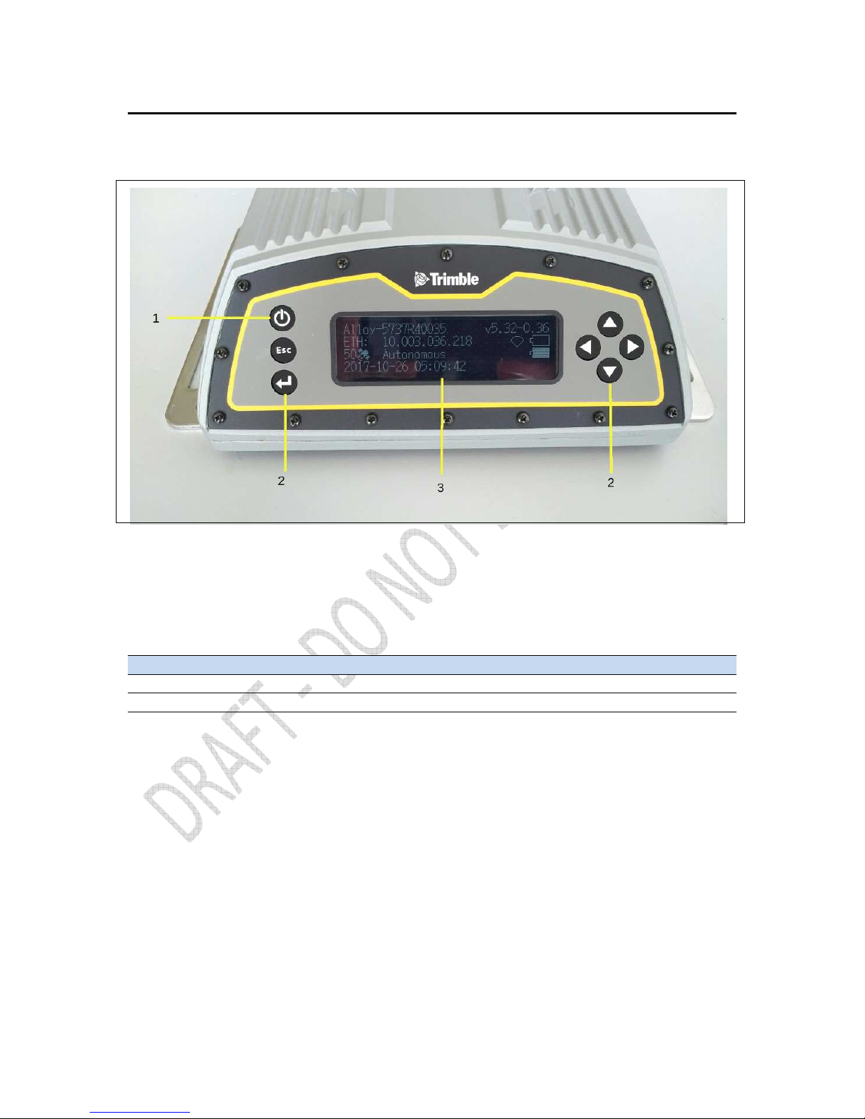
Keypad and display
Feature Description
1 Power LED Indicates if the receiver is turned on or off.
2 Buttons Used to turn on and configure the receiver. (see Button functions, page 36)
3 Display The receiver has a Vacuum Fluorescent Display. This display allows you to see how the
receiver is operating and view the configuration settings.
Figure 2.1 Front view of the Alloy receiver
Page 21
Alloy GNSS reference receiver User Guide
21
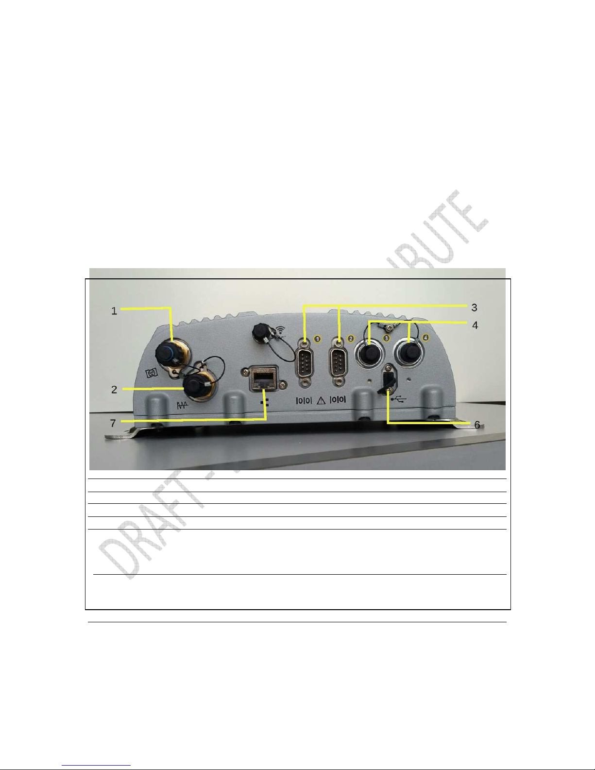
Rear connectors
Connector Type Description
1 TNC Connect to the GNSS antenna
2 BNC 10 MHz external frequency input
3 D9 Full 9-wire RS-232 serial port
4 Lemo (7-pin/0-shell)
(port 2)
• Event input and 1 PPS output using cable (P/N 36451-02)
• Power from a Trimble AC/DC power supply
• 3 wire RS-232 serial communications using a 7-pin/0-shell
Lemo cable (P/N 59044)
6 USB Mini B 5 pin USB. Connect to external USB drive for external
data logging or connect receiver to computer to download
files from receiver as an external device to the computer.
7 RJ45 Jack 10/100 Base-T Ethernet communications
Page 22

22
Alloy GNSS reference receiver User Guide
Batteries and Power
In this chapter:
External power
Battery safety
Battery performance
Charging the Lithium-ion battery
Storing the Lithium-ion battery
Removing the rechargeable
Lithium-ion battery
The Alloy GNSS receiver uses an internal
rechargeable Lithium-ion battery, which can be
replaced only at an Authorized Trimble Service
Center.
The receiver can also be powered by an external
power source that is connected to either of the
Lemo ports.
The operational time provided by the internal
battery depends on the type of measurement and
operating conditions. Typically, the internal battery
provides up to 12 hours operation.
Note – All battery operational tests are carried out
with new, fully charged batteries at room
Page 23

Alloy GNSS reference receiver User Guide
23
temperature, tracking both GPS and GLONASS
satellites while storing and streaming data at 1 Hz.
Older batteries, at temperatures significantly higher
or lower than room temperature, will have a reduced
performance. Power consumption increases with an
increasing number of actively tracked satellites and
well as increasing observation and storage rates.
External power
The receiver uses an external power source in preference to its internal battery. If the receiver is not
connected to an external power source, or if the external power supply fails, the internal battery is
used.
The applied external power must offer between 9.5 V and 28 V DC and must be able to supply at
least 5 W of power. The receiver's internal battery will only charge when the external voltage is
above 12 V DC. Trimble recommends that external supply voltage be above 12 V DC for long-term
installations. This will ensure that the internal battery is charged and ready to compensate for power
supply disruptions.
While carrying out static measurements for postprocessed computations using the internal memory,
if no external power is supplied and the internal battery is drained, the receiver shuts down. No data
is lost and when power is restored, the receiver restarts in the same status as it was when power
was lost.
If for some reason you do not want to use the internal battery as an uninterruptable power supply,
you may disable this feature in the Web user interface. See Chapter 6 for details on the
configuration setting.
WARNING – The external AC power adapter and its associated power cord and plug are not
intended to be installed outdoors, nor in a wet location.
WARNING – Do not power the receiver through external power when operating in a wet
environment or an environment that may become wet. The power input connections must be
sheltered.
WARNING – When you apply DC voltage to this product through the Lemo connector, the DC
voltage must be limited to 28 V DC +0% under both normal and single fault conditions. This product
may present an electrical hazard if the recommended input voltage is exceeded.
Page 24

24
Alloy GNSS reference receiver User Guide
Battery safety
The receiver is powered by a rechargeable internal Lithium-ion battery. Charge and use the battery
only in strict accordance with the instructions below.
WARNING – Do not damage the rechargeable Lithium-ion battery. A damaged battery can cause an
explosion or fire, and can result in personal injury and/or property damage.
To prevent injury or damage:
– Do not use or charge the battery if it appears to be damaged. Signs of damage include, but are not
limited to, discoloration, warping, and leaking battery fluid.
– Do not expose the battery to fire, high temperature, or direct sunlight.
– Do not immerse the battery in water.
– Do not use or store the battery inside a vehicle during hot weather.
– Do not drop or puncture the battery.
– Do not open the battery or short-circuit its contacts.
WARNING – Avoid contact with the rechargeable Lithium-ion battery if it appears to be leaking.
Battery fluid is corrosive, and contact with it can result in personal injury and/or property damage.
To prevent injury or damage:
– If the battery leaks, avoid contact with the battery fluid.
– If battery fluid gets into your eyes, immediately rinse your eyes with clean water and seek medical
attention. Do not rub your eyes!
– If battery fluid gets onto your skin or clothing, immediately use clean water to wash off the battery
fluid.
Battery performance
To optimize battery performance and extend battery life:
• Fully charge all new batteries before use.
• Batteries perform best when they are not used at extreme temperatures. The receiver is
designed to operate at –40 °C to +65 °C (–40 °F to +149 °F). However, operation at
temperatures of less than 0 °C (32 °F) can cause a rapid drop in battery life.
• Do not allow a battery that is in storage to discharge to below 5 V.
Page 25

Alloy GNSS reference receiver User Guide
25
Charging the Lithium-ion battery
The rechargeable Lithium-ion battery is supplied partially charged. Charge the battery completely
before using it for the first time. If the battery has been stored for longer than three months, charge
it before use.
The internal battery charges fully in 24 hours when connected to a suitable power source.
WARNING – Charge and use the rechargeable Lithium-ion battery only in strict accordance with the
instructions. Charging or using the battery in unauthorized equipment can cause an explosion or fire,
and can result in personal injury and/or equipment damage.
To prevent injury or damage:
– Do not charge or use the battery if it appears to be damaged or leaking.
– Charge the Lithium-ion battery only within the Alloy receiver. The battery can only be removed by
an authorized Trimble Service Center.
Storing the Lithium-ion battery
If you must store a Lithium-ion battery for long periods, make sure that it is fully charged before it is
stored, and that you charge it at least once every three months while it is stored.
Do not allow a battery that is in storage to discharge to below 5 V. A battery that reaches deep
discharge level (5 V or less) cannot be recharged and must be replaced. (To protect a battery that is
in use from deep discharge, the receiver switches power sources or stops drawing power when the
battery pack discharges to 5.9 V.)
All batteries discharge over time when not in use, and they discharge faster in colder temperatures.
Do not store the receiver at temperatures outside the range –40 °C to +70 °C (–40 °F to +158 °F).
The receiver has an internal Lithium-ion battery. The internal battery will only charge from an
external power source that delivers more than 12 volts, for example, an AC power adaptor. The
receiver is supplied with a mains power supply unit that recharges the battery inside the receiver
when it is connected through the adaptor to either of the Lemo ports. When you use the receiver in
a long-term deployment, Trimble recommends that you use this power supply or another that
Page 26

26
Alloy GNSS reference receiver User Guide
provides at least 12 V DC at all times to keep the internal battery charged. This will ensure that the
internal battery provides an uninterrupted power supply that will keep the receiver operational for
up to 15 hours after a power failure.
Keep all batteries on continuous charge when not in use. You can keep batteries on charge
indefinitely without damage to the receiver or to the batteries.
Removing the rechargeable Lithium-ion battery
The internal Lithium-ion battery should be removed only at an authorized Trimble Service Center. If
the battery is removed at an unauthorized service center, the remaining warranty on the product
will be void.
Page 27

Alloy GNSS reference receiver User Guide
27
Setting up the Receiver
In this chapter:
Setup guidelines
Connecting the receiver to external
devices
Installing the tripod clip
This chapter describes best practices for setting up
the equipment, and outlines the precautions that
you need to take to protect the equipment. It also
describes how to connect the receiver to external
devices.
The antenna installation guidelines offered here are
the minimum standards: When installing a geodetic
antenna to gather precise observation data, always
follow recommended CORS installation practices to
the greatest extent possible.
Page 28

28
Alloy GNSS reference receiver User Guide
Setup Guidelines
When you set up the receiver, follow these guidelines.
Environmental Conditions
The receiver has a waterproof housing. However, you should take reasonable care to keep the unit
dry.
To improve the performance and long-term reliability of the receiver, avoid exposing the receiver
to extreme environmental conditions, such as:
• Water
• Heat greater than 65 °C (149 °F)
• Cold less than -40 °C (-40 °F)
• Corrosive fluids and gases
Sources of Electrical Interference
Avoid locating the GNSS antenna near the following sources of electrical and magnetic noise:
• Gasoline engines (spark plugs)
• Televisions and computer monitors
• Alternators and generators
• Electric motors
• Equipment with DC-to-AC converters
• Fluorescent lights
• Switching power supplies
• Arc welding equipment
Uninterruptible Power Supply
Trimble recommends that you use an uninterruptible power supply (UPS) to power the receiver.
The internal battery can also operate as a UPS for up to 15 hours. A UPS protects the equipment
from power surges and spikes, and keeps the receiver running during short power outages.
Page 29

Alloy GNSS reference receiver User Guide
29
Items operating with the receiver, such as an Ethernet switch, should also be on a UPS to provide
uninterrupted operation.
For more information, contact your local Trimble dealer.
Lightning and surge protection
Trimble recommends that you install lightning protection equipment at permanent sites. All
connections to the receiver should have surge protection. Typically, the minimum protection
should include a surge protector in the antenna feed line, on the Ethernet connection between the
receiver and the local area network, as well as on the receiver's power supply system. If serial
devices are attached to the receiver, those serial connections should also be provided with surge
protection. Also, protect any communications and power lines at building entry points. If you use
other antennas, such as a radio modem that distributes real-time correction messages or a lastmile radio, install surge protection on those antenna feeds as well.
No surge protection devices can offer protection unless they are connected to an excellent ground
using very low impedance conductors. Equipment damage caused by electrical surges occurs in
many permanent installations even though surge protection is in place. Commonly, this is because
the grounding system used was designed to protect against AC electrical hazards rather than to
dissipate the sudden, high current surges caused by lightning. Please consult with a lightning
protection expert or research the topic when planning permanent installations.
For more information, contact your local Trimble Infrastructure dealer, or go to the websites of
surge protection and grounding system manufacturers. Trimble customers have reported good
results when using products from the following manufacturers:
• Polyphaser (www.polyphaser.com)
• Huber and Suhner (www.hubersuhner.com)
• Harger (www.harger.com)
• Hyperlink Technologies (www.hyperlinktech.com)
Placing the antenna
The antenna location will have a significant effect on the quality of your Alloy receiver's
performance. In temporary developments it may not always be possible to set up on an ideal
location with an excellent sky view. However, when installing a permanent station, be sure to plan
the antenna location and mounting system carefully.
The general requirements for the antenna location and mount are:
Page 30

30
Alloy GNSS reference receiver User Guide
• Clear sky from the zenith to the horizon to a 100 m (328 feet) radius, in all directions (360
degrees).
• Mounted 1.5 m (5 feet) above any nearby signal reflectors.
• Separation of at least 300 m (984 feet) from radio signal transmitters.
• Mount stability that is not influenced by thermal expansion, wind loading, or soil
expansion/contraction.
For additional information on this topic, research the reference antenna installation guidelines
published by:
• the US National Geodetic Survey
(http://www.ngs.noaa.gov/PUBS_LIB/CORS_guidelines.pdf)
• the International GNSS Service
(http://igscb.jpl.nasa.gov/network/guidelines/guidelines.html)
Connecting the receiver to external devices
You can connect a Alloy receiver to the following devices:
• GNSS antenna
• Dial-up modems
• Radio modems
• Meteorological and tilt sensors
GNSS Antenna
The Alloy receiver provides a TNC-type female connector for connecting to an antenna. The
receiver is intended for use with a Zephyr™ Geodetic Model 2 antenna or a Trimble GNSS Choke
Ring antenna.
Antenna Cabling
Many permanent GPS installations have unique cabling requirements. Depending on the available
infrastructure, you may need to mount the antenna a substantial distance from the receiver.
The Alloy receiver can withstand a loss of 12 dB between the antenna and the receiver. The degree
of loss in a coaxial cable depends on the frequency of the signal passing through it. The following
table lists some common types of cable and the maximum length you can use before you need an
inline amplifier.
Page 31

Alloy GNSS reference receiver User Guide
31
Cable type Maximum length for use without an inline amplifier
LMR-400 70 m (230 ft)
LMR-500 85 m (280 ft)
LMR-600 106 m (350 ft)
Heliax LDF4-50 165 m (540 ft)
Heliax. LDF4.5-50 225 m (740 ft)
Dial-up modems
The receiver can make automated dial-out connections to an Internet service provider. To set up
the receiver to do this, in the Web interface select Network Configuration/PPP.
You can set up a streaming service, such as RT17/RT27 raw GNSS data, CMR™, or RTCM corrections
over a serial port. When using a modem on the serial port, the modem itself must perform the
auto-answer function.
Radio modems
You can connect the receiver to an external radio through the Lemo ports or the 9-pin serial port,
whether or not the Ethernet port is in use. Trimble radios are supplied with the required cables to
connect to the Lemo ports. The Alloy receiver supports the following Trimble base radios:
• TRIMMARK™ 3 (firmware 1.26 or later)
• Trimble HPB450
• Trimble PDL450
To use an external radio with the receiver, you need an external power source for the radio.
Configure the external radio separately, using the configuration program for the external radio.
To configure the Alloy receiver for RTK operation, you must do all of the following:
• Enable the RTCM or CMR RTK corrector stream on the selected serial port.
• Set the reference station coordinates and broadcast ID using the front panel of the
receiver or the Web user interface.
Meteorological and tilt sensors
You can connect an external meteorological or tilt sensor to any of the three available serial ports
on the Alloy receiver.
The sensor responds to a request for information. The request and the response are time tagged
and are entered into the Alloy receiver's stored files and streamed observation data.
Page 32

32
Alloy GNSS reference receiver User Guide
Note – The sensor's serial configuration must include 8 data bits. Some sensors default to
7 data bits and this is incompatible with the Alloy receiver.
Supported sensors include the following:
• Paroscientific Met3, Met3A, Met4, and Met4A
• Vaisala PTU300
• Applied Geomechanics D700 and MD900 series
The I/O Configuration / Port Configuration menu allows you to enter the serial port settings and
control commands for a meteorological/tilt sensor.
Other external devices
For all other external devices, connect to a suitable communications port and then configure that
port for the connected device.
Installing the tripod clip
For campaign operations or temporary base deployments, the standard mounting base can be
replaced with a tripod clip:
1. Remove the standard mounting base by unscrewing the four bottom screws that are
located beneath the rubber end cap trim.
2. Use the two provided screws to attach the tripod clip to the two holes located at the
bottom of the front panel of the receiver.
Page 33

Alloy GNSS reference receiver User Guide
33
Configuring the Receiver Using
the Keypad and Display
In this chapter:
Button functions
Power button operations
Home screen
Status screens
Setting up the receiver as a base station
Setting up the receiver as part of an
Ethernet configuration
Setting up the receiver to log Data
The Alloy receiver features a front panel user
interface with a keypad and as two-line
alphanumeric display (see page 18). This interface
allows you to configure many of the receiver’s
features without using an external controller or
computer.
Page 34

34
Alloy GNSS reference receiver User Guide
Button functions
The Alloy has seven buttons on the front panel to control the receiver. Use the buttons to turn the
receiver on and off and to check or change the receiver settings.
Power button operations
Press the power button to turn the receiver on and off. In addition, you can tap the power
button to return to the Home screen, or hold down the Power button to perform the following
operations:
Button
Name
Function
Power
Turn the receiver on/off. To turn the receiver off, hold the power button for
two seconds.
Escape Return to the previous screen or cancel changes being made on a screen.
Enter Advance to the next screen or accept changes made on a screen.
Up Move the cursor between multiple fields on a screen or make changes.
Down Move the cursor between multiple fields on a screen or make changes.
Left Move the cursor between characters in an editable field.
Right
Move the cursor between characters in an
editable field.
This button also initiates edit mode for the current field
To…
Hold the power
button for…
Notes
Turn off the receiver
Two seconds
The display shows a countdo
wn timer. When the display goes
Page 35
Alloy GNSS reference receiver User Guide
35
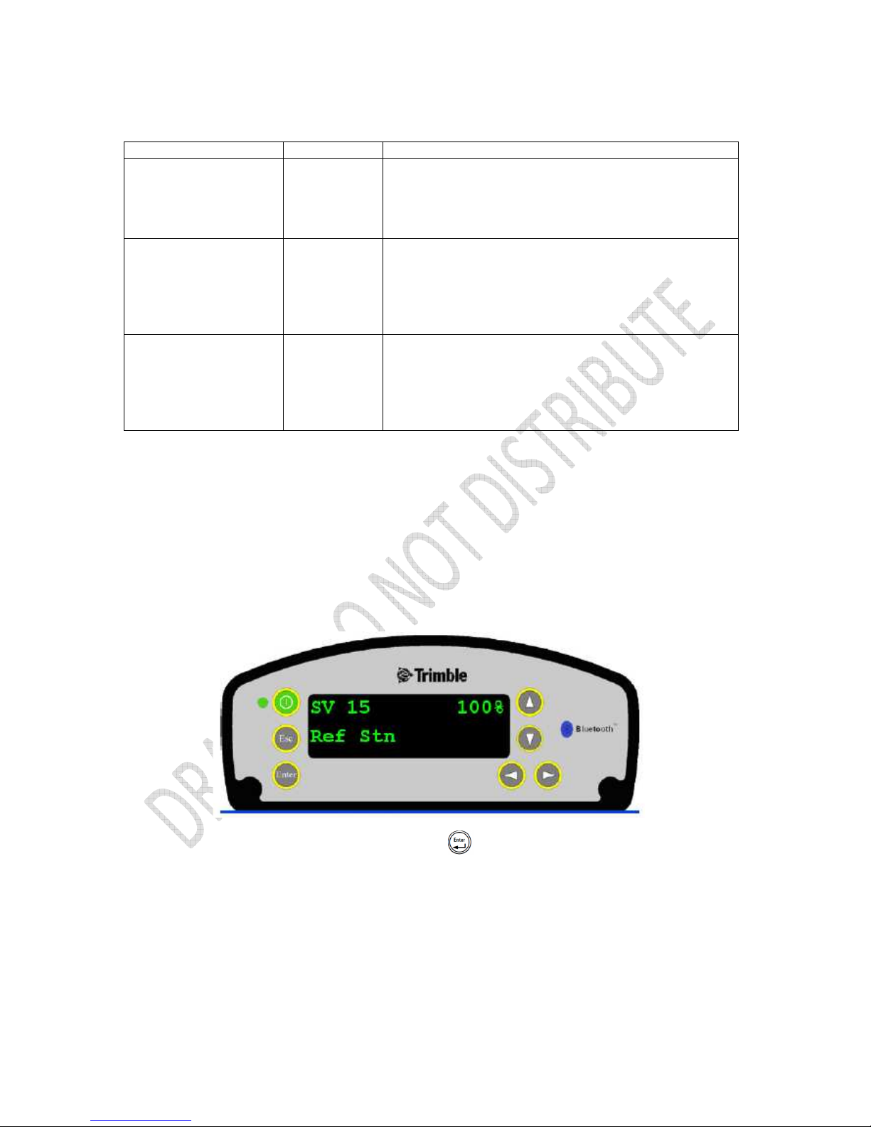
Home screen
The Home screen is the main screen displayed on the Alloy receiver. The receiver always returns to
this screen if displaying any other screen and left idle for 60 seconds.
The Home screen indicates:
• the number of satellites being tracked
• the internal battery power remaining
• the current operation mode
• if the receiver is logging data (the operating mode field will show the word Logging every
three seconds is logging is enabled)
The front panel will go dark after a short period of inactivity as a power-saving feature. If the
display is not lit and the receiver is on, press to reactivate the display. If required, you can
disable this power-saving feature in the Web interface.
Status screens
blank, release the power button.
Clear the almanac,
ephemeris, and SV
information
15 seconds
The display shows a countdown timer. When the display goes
blank, continue to hold the power button. The display shows a
countdown time to clear the almanac and ephemeris. When the
counter reaches 0, release the power button.
Reset the receiver to its
factory defaults and
the default application
file
35 seconds
The display shows a countdown timer. When the display goes
blank, continue to hold the power button. The display shows a
countdown to clear the almanac and ephemeris. When the
counter reaches 0, continue to hold the power button. The
display indicates a countdown to resetting the receiver. When
the counter reaches 0, release the power button.
Force the receiver to
power down
At least 60
seconds
If the method
above does not work, use this method to force
the receiver to turn off. When the Power LED goes off, release
the power button.
Note – All data stored in the receiver is lost when the receiver is
forced to power down.
Page 36

36
Alloy GNSS reference receiver User Guide
The Alloy receiver has several status screens so that you can review the receiver’s current settings.
To access these screens, press or when the Home screen is displayed. The status
screens provide the following information:
• Position solution
• CMR and RTCM IDs
• Base name and code
• Latitude, longitude, and height
• Antenna type
• Antenna height and measurement point
• Receiver firmware version and date
• Receiver serial number
• Current IP address
• Current subnet mask
• Current gateway
Setting up the receiver as a base station
The Alloy receiver can be set up for Ethernet configuration and for real-time outputs so that the
receiver can be used as a base station (also known as a reference station). To set up the receiver as
a base station, use the receiver keypad.
The receiver uses a “step-by-step” configuration method to ensure that all appropriate settings are
reviewed and set. Press to move between steps in the configuration process.
Configuring the receiver as a base station
1. From the Home screen, press to move to the next screen.
The Operation Mode screen appears. Use this screen to configure the reference station
setup, Ethernet configuration, system setup, or to view the SV (satellite) status.
2. As reference station setup is the default, press to move to the next screen.
The Base Station screen appears. Use this screen to select if the receiver is going to use a
“Here” position or if the current coordinates in the receiver will be edited.
3. Do one of the following:
- Press to edit the current position.
Edit Current begins to flash. This indicates that you can now edit this setting. Press
to change to New Base (Here). Press to accept the change. The current
coordinates that the receiver is using will be used as the base station coordinates.
- Continue to the next step and manually enter the coordinates. Press again.
4. Press to move to the next screen.
Page 37

Alloy GNSS reference receiver User Guide
37
Changing the name and description of the base station
The Base Name screen appears.
1. Press to edit the name of the base station. The name can be up to 16 characters.
2. Press or to select the character to edit and then press or to change it.
When finished, press to accept the change.
3. Press to move to the next screen.
The Base Code screen appears.
4. Press to edit the code (description) of the base station.
5. Press or to select the character to edit and press or to change it.
When finished, press .
6. Press to move to the next screen.
Setting the reference latitude, longitude, and height of the base station
The Base Latitude screen appears.
1. Press to edit the reference latitude of the base station.
2. Press or to select the character to edit and then press or to change it.
When finished, press .
3. Press to move to the next screen.
The Base Longitude screen appears.
4. Press to edit the reference longitude of the base station.
5. Press or to select the character to edit and then press or to change.
When finished, press .
6. Press to move to the next screen.
The Point Height screen appears.
7. Press to edit the ellipsoidal height of the base station.
8. Press or to select the character to edit and then press or to change.
When finished, press .
9. Press to move to the next screen.
Measuring and changing the antenna height
The Antenna Type screen appears.
1. Press to select the type of antenna used with the receiver.
2. Press or to select an antenna type. When finished, press .
3. Press to move to the next screen.
Page 38

38
Alloy GNSS reference receiver User Guide
The Measured To screen appears.
4. Press to select how the antenna height is measured.
5. Press or to select a measurement method. When finished, press .
6. Press to move to the next screen.
The Antenna Height screen appears.
7. Press to edit the antenna height.
8. Press or to select the character to edit and then press or to change it.
When finished, press .
9. Press to move to the next screen.
Outputting corrections
The Output screen appears.
4. Press to edit the name of the port which will be used to output corrections.
5. Press or to select the port (1, 2, or 3). When finished, press .
6. Press to select the Format field and then press to edit this field.
7. Press until the required format choice is flashing.
8. Press to move to the next screen.
Data logging
The Logging screen appears.
1. When you have configured the outputting corrections, press to set up internal
logging on the receiver.
2. Press or to select the logging rate. Press to accept.
3. Press to select Files. Press to edit and press or to select the
appropriate length of time to log data for. When finished, press .
4. Press to move to the next screen.
Outputting observations
The RT27 screen appears.
1. When you have configured the data logging configuration, press to set up
RT27 message output from the receiver.
Page 39

Alloy GNSS reference receiver User Guide
39
2. Press or to select the output port. Press to accept.
3. Press to move the cursor to the output rate. Press to edit and then press
or to select the rate at which RT27 messages will be output. Press to
accept.
4. Press to move to the next screen.
The Home screen appears. Base station setup is now complete.
Setting up the receiver as part of an Ethernet configuration
1. From the Home screen, press .
The Operation Mode screen appears. Use this screen to select if you want to configure the
base station setup, Ethernet configuration, or system setup, or to view the SV status.
2. As reference station setup is the default, press so that the Ref Stn Setup message is
flashing.
3. Press to select Ethernet config.
4. Press twice to edit the configuration. The DHCP menu appears.
5. Press to select the type of IP address to set up.
6. Press or to move through the options. You can choose either Enabled (the
default) or Static IP address to program the Ethernet manually. When finished, press .
7. Press to move to the next screen. The IP address appears.
8. Press to edit the IP address.
9. Press or to select the number to edit and then press or to change.
When finished, press .
Note – Editing starts from the right.
10. Press to move to the next screen. The subnet mask is shown.
11. Press to edit the subnet mask address.
12. Press or to select the number to edit and then press or to change.
When finished, press .
Note – Editing starts from the right.
13. Press to move to the next screen. The gateway is shown.
Page 40

40
Alloy GNSS reference receiver User Guide
14. Press to edit the default gateway address.
15. Press or to select the number to edit and then press or to change.
When finished, press .
Note – Editing starts from the right.
16. Press to move to the next screen. The Home screen appears. Ethernet setup is now
complete.
Note – If you change the IP address, restart the receiver for the changes to take effect.
You can also use the keypad to configure the system setup or to view the satellite (SV) status
using the same process as outlined in this chapter.
Setting up the receiver to log data
The Alloy receiver can be set up to log data using the front panel.
The receiver supports up to five independent sessions: Only the Default session parameters
can be configured using the front panel. The remaining four sessions can be activated from the
front panel but their configuration must be performed beforehand using the web interface.
1. From the Home screen, press .
The Operation Mode screen appears.
2. As reference station setup is the default, press repeatedly to move through the menu
choices until Logging is displayed.
The Logging screen allows you to edit the settings for the Default logging session.
3. Do one of the following:
– Press to edit the default session logging rate. Press or to select the
desired rate and then press .
– Press to move to the logging rate field. Press to edit the logging rate.
Press to select a rate.
To store the new settings, press .
4. Press to move to the next screen.
Enabling logging sessions
The Logging Session screen appears.
1. Press to change the session to be enabled. Press or to move among the
session names. With the desired session name displayed, press to enable editing.
Page 41

Alloy GNSS reference receiver User Guide
41
Note – If you have not set up an additional session using the web interface, you will only be
able to select the "Default" session. Additionally, external USB logging is only configurable via
the web interface.
2. Press to move to the On/Off field.
3. Press to edit the setting.
4. Press to change the setting to the required state. When finished, press .
5. Press to move to the next screen.
Configuring the Receiver Settings
6
In this chapter:
Configuring Ethernet settings
Configuring the Alloy receiver using a
web browser
You can configure the Alloy receiver to perform a
wide variety of functions. This chapter describes the
configuration methods other than the front panel
display, and explains when and why each method is
used.
The WinFlash utility described in this chapter is used
primarily to update the receiver firmware and
configure the Ethernet settings in the Alloy receiver.
Page 42

42
Alloy GNSS reference receiver User Guide
Configuring Ethernet settings
The receiver has an Ethernet port in order to connect to an Ethernet network. You can use the
Ethernet network to access, configure, and monitor the receiver. No serial cable connection to the
receiver is necessary.
The receiver has the following Ethernet settings:
• IP setup: Static or DHCP
• IP address
• Netmask
• Broadcast
• Gateway
• DNS address
• HTTP port
•
The default setting for the HTTP port is 80. The HTTP port is not assigned by the network. HTTP port
80 is the standard port for web servers. This allows you to connect to the receiver by entering only
the IP address of the receiver in a web browser. If the receiver is set up to use a port other than 80,
you will need to enter the IP address followed by the port number in a web browser.
Example of connecting to the receiver using port 80: http://169.254.1.0
Example of connecting to the receiver using port 4000: http://169.254.1.0:4000
The default setting of the receiver is to use DHCP. Using DHCP enables the receiver to automatically
obtain an IP address, Netmask, Broadcast, Gateway, and DNS address from the network.
When a receiver is connected to a network using
DHCP, an IP address is assigned to the receiver
by the network. To verify the IP address of the
receiver, select the up button from the keypad
when the Home screen is displayed. The
Ethernet IP address appears as shown.
Page 43

Alloy GNSS reference receiver User Guide
43
If your network installation requires the receiver to be configured with a static IP address, you can
configure the Ethernet settings either using the front panel as described in the Chapter 5,
Configuring the Receiver Using the Keypad and Display, via the web server or the WinFlash utility.
The web server can be only used when the receiver is connected to a network and has a valid
Ethernet configuration.
Use the WinFlash utility to configure the Ethernet settings of a receiver that is to be connected to a
network that requires static IP addresses:
1. Contact the network administrator for the correct settings for the receiver.
2. Use the serial cable provided with the receiver to connect the receiver to a computer
running the WinFlash utility.
3. Turn on the receiver.
4. On the computer, start the WinFlash utility.
5. From the Device Configuration screen:
a. From the Device type list, select Trimble Alloy Receiver.
b. From the PC serial port list, select the appropriate PC serial port.
Page 44

44
Alloy GNSS reference receiver User Guide
c. Click Next.
6. From the Operation Selection screen, select Configure Ethernet settings, and then click
Next:
Page 45
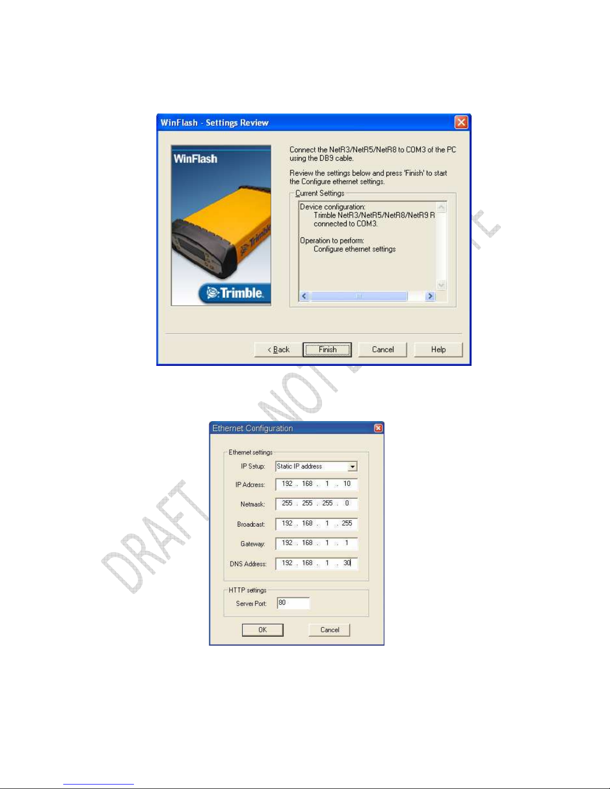
Alloy GNSS reference receiver User Guide
45
7. From the Settings Review screen, click Finish:
Once the WinFlash utility connects to the receiver, the Ethernet Configuration
dialog appears.
8. Enter the network settings in the Ethernet Configuration dialog. Click OK:
The Broadcast setting is the IP address that is used to broadcast to all devices on the subnet. This is
usually the highest address (usually 255) in the subnet.
Page 46
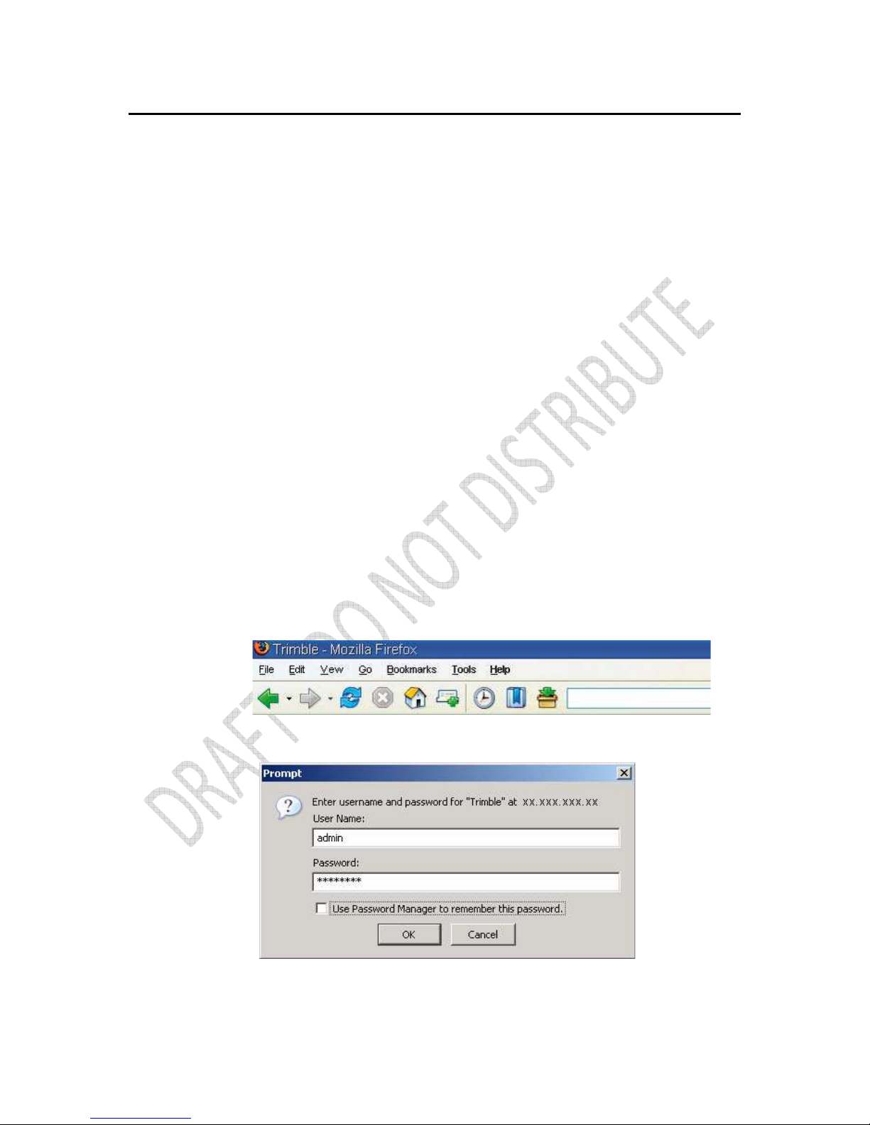
46
Alloy GNSS reference receiver User Guide
Configuring the Alloy receiver using a web browser
The receiver can be configured using the keypad and display, or a web browser. This section
describes how to set up the receiver using a web browser.
Supported browsers
• Mozilla Firefox version 3.0
• Microsoft Internet Explorer version 7.0 for Windows operating systems
Note – Version 8.0 may have problems if the "Use Standards Mode" option is used in that browser
software.
To connect to the receiver using a web browser:
1. Enter the IP address of the receiver into the address bar of the web browser as shown:
2. If security is enabled on the receiver (by default, it is disabled), the web browser prompts
you to enter a username and password:
Page 47
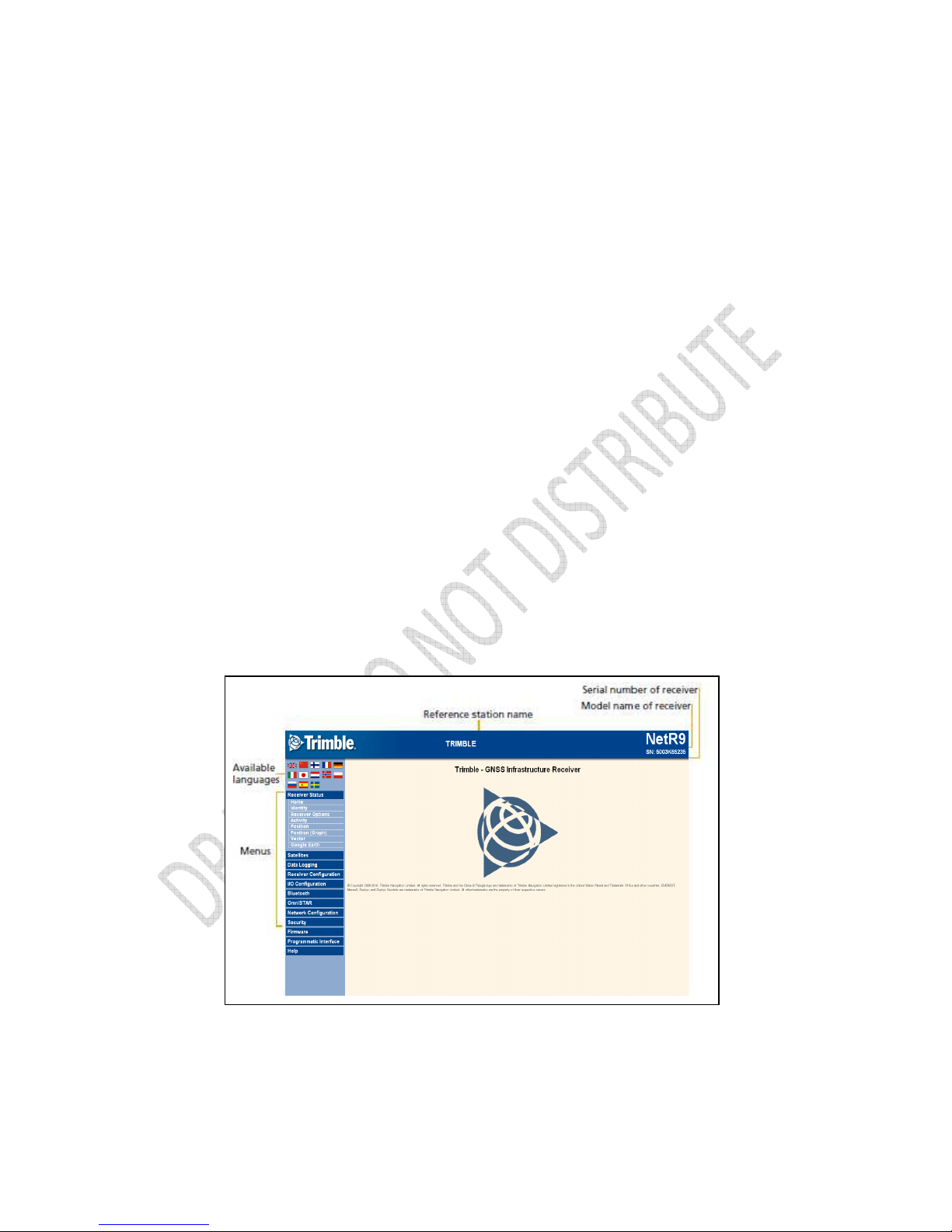
Alloy GNSS reference receiver User Guide
47
The default login values for the receiver are:
- User Name: admin
- Password: password
If you cannot connect to the receiver, the password for the root account may have been changed,
or a different account may be being used. Contact your receiver administrator for the appropriate
login information.
Once you are logged in, the welcome web page (see Figure 6.1) appears.
Figure 6.1 Alloy receiver Home webpage
Page 48

48
Alloy GNSS reference receiver User Guide
Changing the settings
Use the webpage to configure the receiver settings. The web interface shows the configuration
menus on the left of the browser window, and the settings on the right. Each configuration menu
contains related submenus to configure the receiver and monitor receiver performance.
A summary of each configuration menu is provided here.
To display the web interface in another language, click the corresponding country flag.
The web interface is available in the following languages:
• English
• Chinese
• German
• Russian
• French
• Spanish
• Japanese
• Dutch
• Norwegian
• Polish
• Swedish
• Italian
Receiver Status menu
The Receiver Status menu provides a quick link to review the
receiver’s available options, current firmware version, IP address,
temperature, runtime, satellites tracked, current outputs,
available memory, position information, and more.
Receiver Status – Identity
The Receiver Status – Identity screen shows a list of unique receiver items, including the
Ethernet MAC address and the Bluetooth MAC address. It also lists variable items, including the
current Ethernet IP address and the firmware version:
Page 49

Alloy GNSS reference receiver User Guide
49
Receiver Status – Receiver Options
The Receiver Status – Receiver Options screen lists the installed options and limits of the receiver
platform. Additionally, this page displays the current firmware warranty date and allows the
upload of new codes to the receiver. This is used to enter new firmware warranty date codes.
Page 50

50
Alloy GNSS reference receiver User Guide
Receiver Status – Activity
The Receiver Status – Activity screen lists several important items to help you understand how the
receiver is being used and its current operating condition. Items include the identities of currently
tracked satellites, files being logged, data streams being input and output, the receiver's internal
temperature, how long the receiver has been operational, power source voltages, and the state of
Page 51
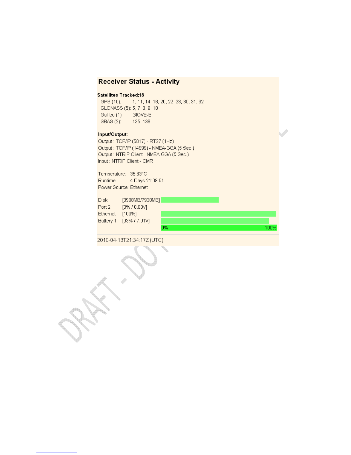
Alloy GNSS reference receiver User Guide
51
the internal battery. With this information, it is easy to tell exactly what functions the receiver is
performing.
Receiver Status – Position
The Receiver Status – Position screen provides all relevant information pertaining to the receiver's
position solution. If the Alloy receiver is operating as a reference station, this information may be of
minimal concern, however, if the receiver is acting as a Rover Integrity Monitor, this menu provides
Page 52
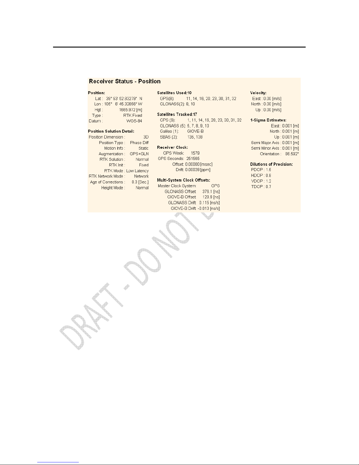
52
Alloy GNSS reference receiver User Guide
all of the information needed to assess the quality of the receiver's RTK position and therefore, the
quality of network correctors.
Receiver Status – Position (Graph)
The Receiver Status – Position (Graph) screen graphically displays the receiver’s position and fix
status. These plots display the values of Height, East, North, East/North, and PDOP/# SVs. The
operator can choose from 10-second or high rate updates.
Page 53

Alloy GNSS reference receiver User Guide
53
Receiver Status – Vector
The Receiver Status – Vector screen provides information on the vector between the
Alloy receiver and its RTK reference station.
Receiver Status – Google Earth
The Receiver Status – Google Earth menu allows the user to request a Google Earth position marker
file for the reference receiver position. This .kmz file can be easily imported into Google Earth to
allow that software to display the receiver's location on a map or aerial view.
Satellites menu
Use the Satellites menu to view satellite tracking details and
enable/disable GPS, GLONASS, Galileo, and SBAS (WAAS/EGNOS,
Page 54

54
Alloy GNSS reference receiver User Guide
and MSAS) satellites. These menus include tabular and graphical displays to provide all needed
information on satellite tracking status. Within this menu it is possible to:
• Manually disable the tracking of satellites.
• Download the latest broadcast ephemeris.
• View various constellation coverage’s.
Satellites – General
The Satellites – General screen provides an overview of satellite tracking status:
Satellites – Tracking Skyplot and Graph
This figure shows the Tracking Skyplot and Graph displays as an example of the graphical views
available in this menu.
Page 55
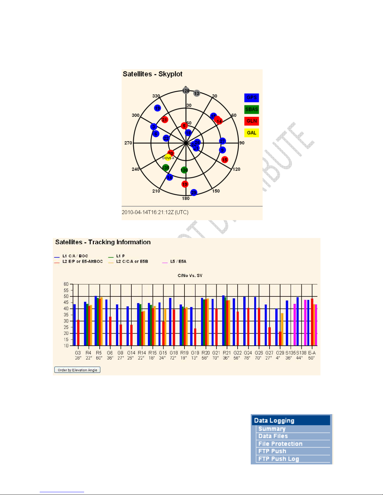
Alloy GNSS reference receiver User Guide
55
Data Logging menu
Use the Data Logging menu to set up the receiver to log static
GNSS data and to view the logging settings. You can configure
Page 56

56
Alloy GNSS reference receiver User Guide
settings such as observable rate, position rate, continuous logging, continuous logging rate, and
whether to auto delete old files if memory is low. This menu also provides the controls for the FTP
push feature.
Data Logging – Summary
The Data Logging – Summary screen displays the files that are currently being stored. It shows their
schedules, their names, whether they are using memory pooling, and in which directory they are
being stored:
To edit a logging session, double-click the session name.
To create a new session, click the New Session button. The Data Logging
Configuration screen appears:
Page 57

Alloy GNSS reference receiver User Guide
57
Use the Data Logging Configuration screen to set all logging parameters and to determine whether
the session files will be affected by the FTP Push, Email Push, and any format conversions.
Data Logging – Data Files
Page 58

58
Alloy GNSS reference receiver User Guide
Use the Data Logging – Data Files screen to view, download, graph, and/or convert the files
currently stored on the receiver:
To download a file, double-click the file name or its icon and then follow the standard procedures
to complete the download.
To select a group of files for download, select the checkbox to the right of the required file names
before double-clicking to start the download. To select all files, click the Select All button.
To delete files, select the checkbox to the right of all files to be deleted and then click the Delete
Selected Files button.
The following six file naming options are available in the Alloy receiver:
Page 59

Alloy GNSS reference receiver User Guide
59
Name Style Description
####JJJx Last four digits of receiver serial number, 3 digit Julian calendar
day, alphabetic session identifier
##########YYYYMMDDhhmm Receiver serial number, 4 digit year, 2 digit month, 2 digit day, 2
digit hour, 2 digit minute of file start
SystJJJh 4 character system identifier, 3 digit Julian calendar day, single
letter hour of day identifier
SystJJJhmm 4 character system identifier, 3 digit Julian calendar day, single
letter hour of day identifier, 2 digit minute of the hour of file start
YYMMDDhh 2 digit year, 2 digit month, 2 digit day, 2 digit hour of file start
YYMMDDhhmm 2 digit year, 2 digit month, 2 digit day, 2 digit hour, 2 digit minute of
file start
SystemYYYYMMDDHHmm System name, 4 digit year, 2 digit month, 2 digit day, 2 digit hour,
minutes
Data Logging – File Protection
Use the Data Logging – File Protection screen to configure the protection of stored data files when
an event signal is received. This feature allows important data to be protected from the standard
memory pool automatic deletion function. The idea is that an event input from an external sensor,
such as a seismic detector, will protect data from automatic deletion for a time period before and
after the event. This ensures that this data is available for later study.
You must manually delete protected data to remove it from system memory.
Data Logging – FTP Push
Page 60
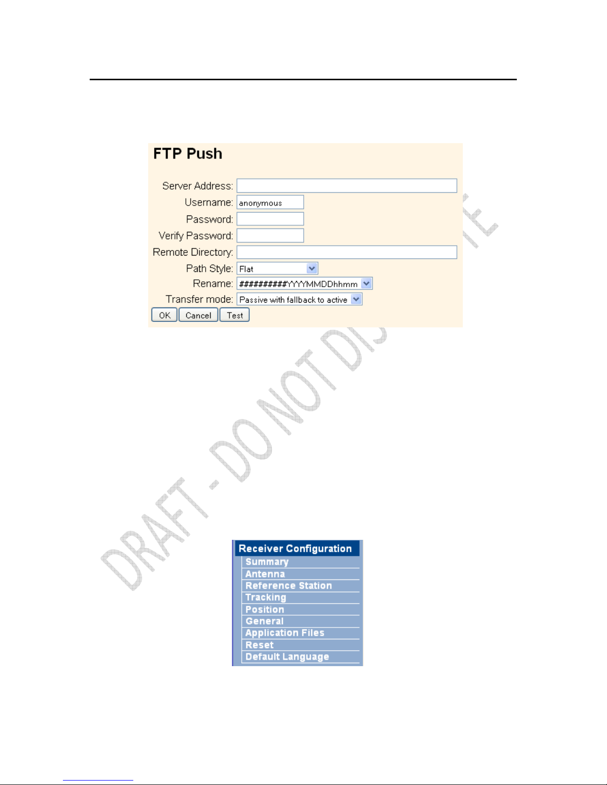
60
Alloy GNSS reference receiver User Guide
Use the Data Logging – FTP Push screen to configure the receiver to push stored files to the FTP
server of your choice. Only files that are configured to use FTP push are transmitted:
Data Logging – FTP Push Log
The Data Logging – FTP Push Log screen shows the status of all FTP Push operations.
Receiver Configuration menu
Use the Receiver Configuration menu to configure settings such as elevation mask and PDOP mask,
the antenna type and height, the reference station position, and the reference station name and
code.
Receiver Configuration – Summary
Page 61
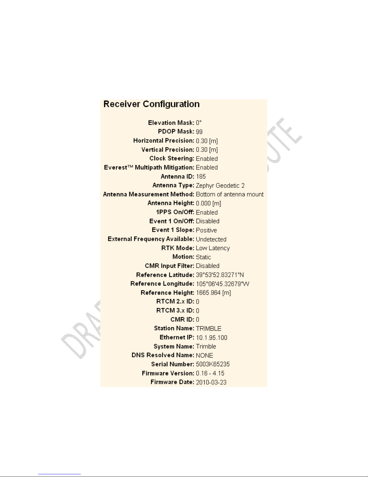
Alloy GNSS reference receiver User Guide
61
The Receiver Configuration – Summary screen provides an overview of the status of many of the
important configuration items:
Receiver Configuration – Antenna
Page 62

62
Alloy GNSS reference receiver User Guide
Use the Receiver Configuration – Antenna screen to configure all of the items relating to the GNSS
antenna. You must enter the correct values for all antenna-related fields as the choices you make
will significantly affect the accuracy for logged data and broadcast RTK correctors:
Receiver Configuration – Reference Station
Use the Receiver Configuration – Reference Station screen to configure settings such as the station
coordinates and the broadcast station identifiers. You must enter accurate information in these
fields as this data can significantly affect the accuracy of logged data files and broadcast RTK
correctors:
Receiver Configuration – Tracking
Page 63

Alloy GNSS reference receiver User Guide
63
Use the Receiver Configuration – Tracking screen to determine whether Everest technology and
clock steering are used. This screen also allows you to select which signals relating to particular
satellites are to be stored:
Receiver Configuration – Position
Use the Receiver Configuration – Position screen to configure settings relating to using the receiver
as a Rover Integrity Monitor.
Receiver Configuration – General
Page 64

64
Alloy GNSS reference receiver User Guide
Use the Receiver Configuration – General screen to determine:
• Whether event signals and an external frequency source will be used.
• Choose to output a one-pulse-per-second signal (1 PPS).
• Disable the use of the internal battery as an uninterruptable power supply.
• Enable Power over Ethernet.
• Configure power on and shutdown voltages.
• Configure VFD settings.
Note – The VFD Configuration item determines whether users can operate the receiver using its
front panel display and keypad. If you disable this feature and Ethernet communications are lost,
the only way to regain control of the receiver will be to perform a hard reset of the receiver using
the Power button.
Receiver Configuration – Application Files
Use the Receiver Configuration – Application Files screen to configure all of the settings that make
up an application file, save that file, and select an application file for use:
See also Chapter 7 for a complete description of this process.
Receiver Configuration – Reset
Page 65

Alloy GNSS reference receiver User Guide
65
Use the Receiver Configuration – Reset screen to completely or partially reset the receiver:
Receiver Configuration – Default Language
Use the Receiver Configuration – Default Language screen to select the language that the receiver
will display on start up.
I/O Configuration menu
Page 66
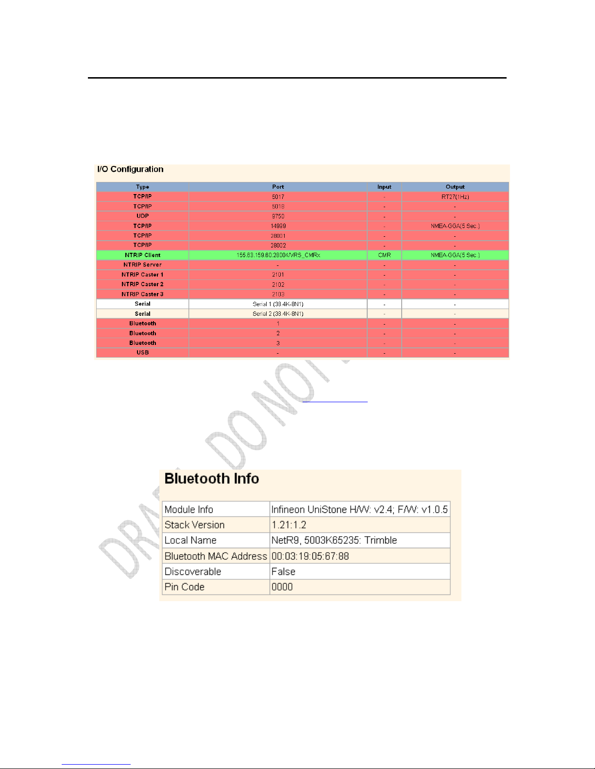
66
Alloy GNSS reference receiver User Guide
Use the I/O Configuration menu to set up all outputs/inputs of the receiver. The receiver can
output CMR, RTCM, NMEA, GSOF, RT17, RT27, or BINEX messages. These messages can be output
on TCP/IP, UDP, serial, or Bluetooth ports.
This figure shows an example of the screen that appears when you select I/O Configuration / Port
Summary.
The Alloy USB port may also be used to access the receiver in USB Device mode. This allows you to
cable your computer to the receiver and browse the internal memory of the receiver as an external
USB device. USB drivers are available from www.trimble.com.
Bluetooth menu
Use the Bluetooth menu to configure Bluetooth settings. This figure shows an example of the
screen that appears when you select Bluetooth/Info:
OmniSTAR menu
Page 67

Alloy GNSS reference receiver User Guide
67
Use the OmniSTAR menu to configure OmniSTAR settings.
This figure shows an example of the screen that appears when you select OmniSTAR/Summary:
Network Configuration menu
Page 68

68
Alloy GNSS reference receiver User Guide
Use the Network Configuration menu to configure Ethernet settings, PPP, Routing Table, Email
Client, Email Alerts, HTTP/HTTPS port, Proxy, FTP port, NTP ports and settings, VFD (Virtual Front
Display), and discovery port settings of the receiver.
The VFD port allows you to use the Alloy Remote Control application to view and navigate the
receiver through a mock display and keypad interface. To allow the Alloy Remote Control to
connect to the receiver, select Network Configuration / VFD to enable the VFD port. A viewing
utility is available on the Trimble.com.
The receiver can notify a system administrator by sending alerts about general status changes in
the receiver as well as warning messages in case of problems to a specified email address. This
requires the use of an SMTP server. To find out how to connect the receiver to the server, contact
your network administrator.
This figure shows an example of the screen that appears when you select Network Configuration /
Ethernet:
Security menu
Page 69

Alloy GNSS reference receiver User Guide
69
Use the Security menu to configure the login accounts for all users who will be permitted to
configure the receiver using a web browser. Each account consists of a username, password, and
permissions. Administrators can use this feature to limit access to other users. By default, security
is disabled to make it easier to configure the receiver. However, Trimble encourages administrators
to enable security to avoid unwanted changes. If security is enabled with anonymous access, it
allows users to browse the receiver settings but they cannot make changes.
This figure shows an example of the screen that appears when you select Security/Configuration.
Firmware menu
Page 70

70
Alloy GNSS reference receiver User Guide
Use the Firmware menu to verify the current firmware and load new firmware to the receiver. You
can upgrade firmware across a network or from a remote location without having to connect to the
receiver with a serial cable.
This figure shows an example of the screen that appears when you select Firmware.
Programmatic Interface menu
Use the Programmatic Interface menu to show, set, and command configurations. The
programmatic interface allows simple HTTP scripting for browser use or for integration into other
web capable platforms. For additional information on supported commands and command
structure, please see Appendix D.
This figure shows an example of the screen that appears when you select the Programmatic
Interface page.
Page 71

Alloy GNSS reference receiver User Guide
71
Default Settings and Application
Files
In this chapter:
Default receiver settings
Resetting the receiver to factory defaults
Using application files to duplicate
receiver settings
Most of the receiver settings are stored in
application files. The default application file,
Default.cfg, is stored permanently in the receiver,
and contains the factory default settings for the
Alloy. Whenever the receiver is reset to its factory
defaults, the current settings (stored in the current
application file, Current.cfg) are reset to the values
in the default application file.
The Alloy receiver extends the use of application
files to allow simplified receiver setting duplication
in multiple receivers. This is sometimes referred to
as receiver cloning and is very useful when preparing
a large group of receivers for a field data collection
campaign.
Page 72

72
Alloy GNSS reference receiver User Guide
Default receiver settings
These settings are defined in the default application file.
Function Factory Default
SV Enable All SVs enabled
General Controls: Elevation mask 0°
PDOP mask 99
RTK positioning mode Low Latency
Motion Static
Lemo Port: Baud rate 38,400
Format 8-None-1
Flow control None
D9 Port Baud rate 38,400
Format 8-None-1
Flow control None
Input Setup: Station Any
NMEA/ASCII (all supported messages) All ports Off
Streamed output All types Off
RT17/RT27/Binary All ports Off
Reference position: Latitude 0°
Longitude 0°
Altitude 0.00 m HAE (Height above ellipsoid)
Antenna: Type Zephyr Geodetic™ Model 2
Height (true vertical) 0.00 m
Measurement method True vertical
Resetting the receiver to factory defaults
To reset the receiver to its factory defaults, press for 35 seconds.
Using application files to duplicate receiver settings
The Alloy receiver allows the extensive use of application files in order to retain a unique receiver
configuration. With the Alloy you can create an application file that includes most of the receiver's
unique configuration settings. That application file can then be copied and placed on another Alloy
receiver to quickly configure it to match the first receiver.
For settings that are not stored in an application file there are also “clone” files. Clone files allow
you to capture all of the settings not included in the application file. Both the clone file and the
application file can be loaded onto other Alloy receivers to give them the exact configuration as the
first receiver. This is called “receiver configuration cloning” or “cloning”. Receiver cloning greatly
reduces the time required to prepare a large group of receivers for field operations.
Page 73

Alloy GNSS reference receiver User Guide
73
The Application Files submenu (select Receiver Configuration/Application Files) provides the
required tools to use these features. There are two variable fields:
Filename allows you to enter a unique name for a stored configuration file.
Operation allows you to select a particular operation from a drop-down list:
The available operations are:
Operation Description
Start Now Applies the selected application file.
Enable Timer Determines at what time and date the receiver will automatically
power-up (wake up) and at what interval it will automatically powerup thereafter.
Disable Timer Overrides all previously configured power-up timer settings.
Delete File Deletes the currently selected application file.
Page 74

74
Alloy GNSS reference receiver User Guide
Operation Description
Download File Allows you to download the currently selected application file to your
browsing computer.
Upload File Allows you to send a file from your browsing computer to the target
Alloy receiver.
Store Current File Allows you to store an application file including all current custom
settings under a new name.
Start Default Now Returns the receiver to factory default settings.
Generate Clone File Allows you to create a named xml file including the receiver
configuration items of your choice.
Install Clone File Tells the receiver to accept the clone file settings in a particular file.
Upload Clone File Allows you to move a clone file from your browsing computer to the
target receiver.
Download Clone File Allows you to move a clone file from the receiver to your browsing
computer.
Delete Clone File Allows you to delete a clone file stored on the receiver.
Upload&Install Clone File Sends a clone file to the target Alloy while telling the receiver to
accept and apply these settings.
Page 75

Alloy GNSS reference receiver User Guide
75
The following generated Clone file selections are available:
Generate Clone File Selection Affected Items
Clone Security Configuration Clones all security settings on the source receiver. See the Security menu.
• All system users with Username, Password, and access settings.
• Security status:
- Enable
- Enable with Anonymous Access
- Disable
Clone IP Port and I/O Streams Clones all Input/Output stream configurations from the source receiver.
Configuration See the I/O Configuration menu.
• TCP/IP Port
• NTripClient
• NTripServer
• NTripCasters
• Serial ports
• Bluetooth ports: If the "Maintain configuration when connection dropped"
switch is set.
Note – The source receiver's clone files will not overwrite any ports currently
configured on the recipient receiver.
Clone Ethernet Boot Configuration Clones all Ethernet settings of the source receiver. See the Network
Configuration/Ethernet menu.
• IP Setup
- DHCP
- Static IP
• IP Address
• Netmask
• Broadcast
• Gateway
• Force DNS Address switch
• DNS Address
• DNS Domain
Note – If the source receiver has a static IP address, you may need to edit the
static IP address of the recipient receiver after the clone file is passed to that
recipient.
Clone HTTP Configuration Clones all HTTP and HTTPS settings of the source receiver. See the
Network Configuration/HTTP menu.
• HTTP Enable switch
• HTTP Server Port
• HTTPS Secure Enable switch
• HTTPS Secure Port
• Certificate Information
Page 76

76
Alloy GNSS reference receiver User Guide
Generate Clone File Selection Affected Items
Clone Email Alert, FTP, NTP Server Clones all Email Alert controls, all FTP/FTP Push controls and NTPServer
Configuration settings.
Email alerts
• Enable switch
• Authorization required switch
• SMTP Server
• SMTP Port
• From Email Address
• Any Alert switches
The user must enter the email address to which the email is to be sent, login,
and the email password.
FTP
• FTP Server Enable switch
• FTP Server Port
• FTP Push Controls
- FTP Server Address
- Remote Directory (at server)
- Path Style
- Rename setting
The user must enter the username and password
NTP server
• External Time Servers
• NTP Port
• Enable switch
Clone Data Logger Configuration Clones all configured Data Logging Sessions from the source receiver.
• Session Name
• Enable switch
• Schedule setting
• Duration
• Measurement Interval
• Smoothing settings
• Position Interval
• File System setting
• Path and Name Style
• Pool setting
• FTP/Email Push switch
Clone Ephemeris and Almanac Clones all Ephemeris and Almanac data from the source receiver for expediting
Data SV tracking of recipient receiver.
• GPS Satellites - SV1~SV32
• SBAS Satellites - SV120~SV138
• GLONASS SV1~SV24
• Galileo GIOVE A and GIOVE B
• NAV Chan 0~11
• SBAS for correction
• WAAS Ephemeris and Iono Bands
• Position
• UTC
•
Almanac Health
Page 77

Alloy GNSS reference receiver User Guide
77
Generate Clone File Selection Affected Items
Clone Miscellaneous (Everything Else)
• Position Controls
- Elevation Mask
- PDOP Mask
- RTK Mode
- Motion
- Precisions
• General Controls
- Event On/Off and Slope
- External Frequency
- Internal Battery UPS setting
- 1PPS On/Off
- Power Over Ethernet Enabled/Disabled
- Ethernet Battery Charging setting
- Shutdown Voltage settings
- VFD Configuration
- VFD Power Saver setting
• Tracking Controls
- Everest setting
- Clock Steering setting
- Signal Enable switches and Options
• Antenna Settings
- Antenna Type
- Measurement Method
- Antenna Height
• Reference Station settings
- Latitude/Longitude/Height
- CMR ID
- RTCM 2.x/3.x ID
- Station Name
- Station Code
• Bluetooth Controls
• OmniSTAR Configuration
- External OmniSTAR Data
- Internal OmniSTAR Demodulator
- SV Name
- Seed with RTK setting
- NAD83>ITRF Transformation switch
Page 78

78
Alloy GNSS reference receiver User Guide
Specifications
8
In this chapter:
General specifications
Physical specifications
Electrical specifications
Communication specifications
This chapter details the specifications for the Alloy
GNSS reference receiver.
Specifications are subject to change without notice.
Page 79

Alloy GNSS reference receiver User Guide
79
General specifications
Feature Specification
Keyboard and display Vacuum Fluorescent Display (VFD), 16 characters by 2 rows
Escape and Enter key for menu navigation
4 arrow keys (up, down, left, right) for option scrolls and data entry
Receiver type GNSS Reference receiver
Antenna type Zephyr Geodetic Model 2 or Trimble GNSS Choke Ring antenna preferred.
Other models supported.
Physical specifications
Feature Specification
Dimensions (L x W x H) 26.5 cm x 13.0 cm x 5.5 cm (10.43 in x 5.12 in x 2.16 in)
Weight 1.75 kg (3.85 lb)
Temperature1
Operating –40 °C to +65 °C (–40 °F to +149 °F)
Storage –40 °C to +80 °C (–40 °F to +176 °F)
Humidity 100% condensing
Ingress protection tested to IP67; waterproof for temporary immersion to a depth of 1 m (3.28 ft);
dustproof
Shock and vibration Designed to survive a 1 m (3.28 ft) drop onto a hard surface.
Shock, non operating Survival to 75 g, 6 mS
Shock, operating To 25 g, 10 msec, saw-tooth
Vibration 10 Hz to 300 Hz 0.04 g2 / Hz; 300 Hz to 1000 Hz -6 dB/Octave
Tracking
• Two advanced Trimble Maxwell 6 GNSS chipsets for a total of 440_channels
• Trimble EVEREST™ multipath signal rejection
• Trimble R-Track™ technology
• High precision multiple correlator for GNSS pseudorange measurements
• Unfiltered, unsmoothed pseudorange measurements data for low noise, low
multipath error, low time domain correlation and high dynamic response
• Very low noise GNSS carrier phase measurements with <1 mm precision in a 1 Hz
bandwidth
• Signal-to-noise ratios reported in dB-Hz
• Proven Trimble low elevation tracking technology
• Current satellite signals tracked simultaneously:
- GPS: L1 C/A, L2C, L2E (Trimble method for tracking L2P), L5
- GLONASS: L1 C/A and unencrypted P code, L2 C/A1 and unencrypted P code
- Galileo GIOVE-A and GIOVE-B
- SBAS: L1 C/A, L5 supporting WAAS, EGNOS and MSAS
- L-Band OmniSTAR VBS, HP and XP
Page 80

80
Alloy GNSS reference receiver User Guide
Feature Specification
Code Differential GNSS Positioning2
Horizontal 0.25 m + 1 ppm RMS
Vertical 0.50 m + 1 ppm RMS
WAAS differential positioning3 typically <5 m 3DRMS
Static GNSS Surveying2
Baseline <30 km
Horizontal 3 mm + 0.1 ppm RMS
Vertical 4 mm + 0.4 ppm RMS
Baseline >30 km
Horizontal 4 mm + 0 ppm RMS
Vertical 9 mm + 0 ppm RMS
Real Time Kinematic Surveying
2,4
Single Baseline <30 km
Horizontal 8 mm + 1 ppm RMS
Vertical 15 mm + 1 ppm RMS
Networked RTK5
Horizontal 8 mm + 0.5 ppm RMS
Vertical 15 mm + 0.5 ppm RMS
Initialization time typically <10 seconds
Initialization reliability typically >99.9%
1
The internal battery will operate from –20 °C to +50 °C (–4 °F to +122 °F). The internal battery charger will
operate from 0 °C to 40 °C (32 °F to 104 °F).
2
Accuracy may be subject to degradation by multipath interference, obstructions, satellite geometry and
atmospheric conditions. Always follow recommended survey practices.
3
Depends on WAAS/EGNOS system performance.
4
Alloy limited to 1,000 m RTK baseline length.
5
Networked RTK PPM values are referenced to the closest physical base station.
Page 81

Alloy GNSS reference receiver User Guide
81
Electrical specifications
Feature Specification
Power
Internal Integrated internal battery 7.4 V, 7800 mA-hr, Lithium-ion
Internal battery can operate as a UPS in the event of external power source
outage
Internal battery will charge from external power source when input voltage is
>12 V or via Power over Ethernet supply
External Power input on Lemo 7P0S has a user-defined cut off threshold of 9.5 V or
higher.
Power source supply (Internal / External) is hot swap capable in the event of
power source removal or cut-off
Power input on Lemo ports is 9.5 V to 28 V DC external power input with overvoltage protection
Receiver will auto power on when connected to external power of a userdefined voltage. The default value is 15 V.
Power over Ethernet Requires a Class 3 Ethernet power supply.
Power consumption 3.8 W nominal, dependent upon user settings
Reference station operation Up to 12 hours
times on internal battery
Regulatory RoHS
China RoHS
FCC Part 15.247 FCC certifications
Class B Device FCC Part 15 and ICES-003 compliance
RSS-119 and RSS-247 Industry Canada compliance
CE mark compliance
C-Tick mark compliance
UN ST/SG/AC.10.11/Rev. 3, Amend. 1 (Li-Ion battery)
UN ST/SG/AC.10/27/Add. 2 (Li-Ion battery)
WEEE
Page 82

82
Alloy GNSS reference receiver User Guide
Communication specifications
Feature Specification
Communications
Port 1 (D9 male) Full 9-wire RS-232
Port 2 (OS 7P Lemo) 3-wire RS-232, 1PPS output, event input, DC power input
Port 3 (USB) 5 pin Mini-B USB, operates in Device or Host modes
RJ45 Jack Ethernet, PoE
Bluetooth1 Fully integrated, fully sealed 2.4 GHz Bluetooth
Receiver position update rate 1 Hz, 2 Hz, 5 Hz, 10 Hz, 20 Hz, and 50 Hz positioning
Data Input and Output CMR, CMR+™, CMRx, RTCM 2.1, 2.3, 2.3, 3.0, 3.1
Outputs NMEA, GSOF, RT17, RT27, BINEX
1
Bluetooth type approvals are country specific. Contact your local Trimble office or representative for more
information.
Page 83

Alloy GNSS reference receiver User Guide
83
NMEA-0183 Output
A
In this appendix:
NMEA-0183 message overview
Common message elements
NMEA messages
This appendix describes the formats of the subset of
NMEA-0183 messages that are available for output
by the receivers. For a copy of the NMEA-0183
Standard, go to the National Marine Electronics
Association website at www.nmea.org.
Page 84

84
Alloy GNSS reference receiver User Guide
NMEA-0183 message overview
When NMEA-0183 output is enabled, a subset of NMEA-0183 messages can be output to external
instruments and equipment connected to the receiver serial ports. These NMEA-0183 messages let
external devices use selected data collected or computed by the GNSS receiver.
All messages conform to the NMEA-0183 version 3.01 format. All begin with $ and end with a
carriage return and a line feed. Data fields follow comma (,) delimiters and are variable in length.
Null fields still follow comma (,) delimiters but contain no information.
An asterisk (*) delimiter and checksum value follow the last field of data contained in an NMEA0183 message. The checksum is the 8-bit exclusive of all characters in the message, including the
commas between fields, but not including the $ and asterisk delimiters. The hexadecimal result is
converted to two ASCII characters (0-9, A-F). The most significant character appears first.
The following table summarizes the set of NMEA messages supported by the receiver, and shows
the page that contains detailed information about each message.
Message Function Page
ADV Position and Satellite information for RTK network operations 84
GGA Time, position, and fix related data 85
GSA GPS DOP and active satellites 86
GST Position error statistics 87
GSV Number of SVs in view, PRN, elevation, azimuth, and SNR 88
HDT Heading from True North 89
PTNL,AVR Time, yaw, tilt, range, mode, PDOP, and number of SVs for 90
Moving Baseline RTK
PTNL,GGK Time, position, position type and DOP values 91
PTNL,PJK Local coordinate position output 92
PTNL,VGK Time, locator vector, type and DOP values 93
PTNL,VHD Heading Information 94
RMC Position, Velocity, and Time 95
ROT Rate of turn 96
VTG Actual track made good and speed over ground 97
ZDA UTC day, month, and year, and local time zone offset 98
Report max DQI=2 NMEA GGA string – When enabled, the Quality Indicator field in the GGA
output message will never be greater than 2 (Differential GPS). Only to be used with legacy systems
that do not fully support the NMEA standard.
Report max correction age 9 sec in NMEA GGA string – When enabled, the Age of differential data
field in the GGA message will never be greater than 9 sec. Only to be used with legacy systems that
do not fully support the NMEA standard.
Report extended information in NMEA GGA and RMC strings - By default this check box is enabled
to provide high precision position data in the NMEA messages. You should clear this check box to
conform to the NMEA standard message length of 82 characters. However, if you do, the precision
of the position and altitude data is reduced by truncating the number of decimal places.
Page 85

Alloy GNSS reference receiver User Guide
85
Common message elements
Each message contains:
• a message ID consisting of $GP followed by the message type. For example, the message
ID of the GGA message is $GPGGA.
• a comma
• a number of fields, depending on the message type, separated by commas
• an asterisk
• a checksum value
Below is an example of a simple message with a message ID ($GPGGA), followed by 13 fields and a
checksum value:
$GPGGA,172814.0,3723.46587704,N,12202.26957864,W,2,6,1.2,18.893,M,-
25.669,M,2.0,0031*4F
Message values
NMEA messages that the receiver generates contain the following values.
Latitude and longitude
Latitude is represented as ddmm.mmmm and longitude is represented as
dddmm.mmmm, where:
• dd or ddd is degrees
• mm.mmmm is minutes and decimal fractions of minutes
Direction
Direction (north, south, east, or west) is represented by a single character: N, S, E, or W.
Time
Time values are presented in Universal Time Coordinated (UTC) and are represented
as hhmmss.cc, where:
• hh is hours, from 00 through 23
• mm is minutes
• ss is seconds
• cc is hundredths of seconds
NMEA messages
When NMEA-0183 output is enabled, the following messages can be generated.
Page 86

86
Alloy GNSS reference receiver User Guide
ADV
Position and Satellite information for RTK network operations
An example of the ADV message string is shown below. Table A.1 and Table A.2 describe the
message fields. The messages alternate between subtype 110 and 120.
$PGPPADV,110,39.88113582,-105.07838455,1614.125*1M
Table A.1 ADV subtype 110 message fields
Field Meaning
0 Message ID $PPGPADV
1 Message sub-type 110
2 Latitude
3 Longitude
4 Ellipsoid height
6 Elevation of second satellite, in degrees, 90° maximum
7 Azimuth of second satellite, degrees from True North, 000° through 359°
8 The checksum data, always begins with *
$PGPPADV,120,21,76.82,68.51,29,20.66,317.47,28,52.38,276.81,22,42.26,198.96*5D
Table A.2 ADV subtype 120 message fields
Field Meaning
0 Message ID $PPGPADV
1 Message sub-type 120
2 First SV PRN number
3 Elevation of first satellite, in degrees, 90° maximum
4 Azimuth of first satellite, degrees from True North, 000° through 359°
5 Second SV PRN number
6 Elevation of second satellite, in degrees, 90° maximum
7 Azimuth of second satellite, degrees from True North, 000° through 359°
8 The checksum data, always begins with *
Page 87

Alloy GNSS reference receiver User Guide
87
GGA
Time, Position, and Fix Related Data
An example of the GGA message string is shown below. Table A.3 describes the message fields.
$GPGGA,172814.0,3723.46587704,N,12202.26957864,W, 2,6,1.2,18.893,M,-
25.669,M,2.0,0031*4F
Table A.3 GGA message fields
Field Meaning
0 Message ID $GPGGA
1 UTC of position fix
2 Latitude
3 Direction of latitude:
N: North
S: South
4 Longitude
5 Direction of longitude:
E: East
W: West
6 GPS Quality indicator:
0: Fix not valid
1: GPS fix
2: Differential GPS fix
4: Real Time Kinematic, fixed integers
5: Real Time Kinematic, float integers
7 Number of SVs in use, range from 00 through 12
8 HDOP
9 Orthometric height (MSL reference)
10 M: unit of measure for orthometric height is meters
11 Geoid separation
12 M: geoid separation is measured in meters
13 Age of differential GPS data record, Type 1 or Type 9. Null field when DGPS is not used.
14 Reference station ID, ranging from 0000 through 1023. A null field when any reference
station ID is selected and no corrections are received.
15 The checksum data, always begins with *
Page 88

88
Alloy GNSS reference receiver User Guide
GSA
GPS DOP and active satellites
An example of the GSA message string is shown below. Table A.4 describes the message fields.
$GPGSA,<1>,<2>,<3>,<3>,,,,,<3>,<3>,<3>,<4>,<5>,<6>*<7><CR><LF>
Table A.4 GSA message fields
Field Meaning
0 Message ID $GPGSA
1 Mode 1, M = manual, A = automatic
2 Mode 2, Fix type, 1 = not available, 2 = 2D, 3 = 3D
3 PRN number, 01 through 32, of satellite used in solution, up to 12 transmitted
4 PDOP-Position dilution of precision, 0.5 through 99.9
5 HDOP-Horizontal dilution of precision, 0.5 through 99.9
6 VDOP-Vertical dilution of precision, 0.5 through 99.9
7 The checksum data, always begins with *
Page 89

Alloy GNSS reference receiver User Guide
89
GST
Position Error Statistics
An example of the GST message string is shown below. Table A.5 describes the message fields.
$GPGST,172814.0,0.006,0.023,0.020,273.6,0.023,0.020,0.031*6A
Table A.5 GST message fields
Field Meaning
0 Message ID $GPGST
1 UTC of position fix
2 RMS value of the pseudorange residuals; includes carrier phase residuals during periods
of RTK(float) and RTK(fixed) processing
3 Error ellipse semi-major axis 1 sigma error, in meters
4 Error ellipse semi-minor axis 1 sigma error, in meters
5 Error ellipse orientation, degrees from true north
6 Latitude 1 sigma error, in meters
7 Longitude 1 sigma error, in meters
8 Height 1 sigma error, in meters
9 The checksum data, always begins with *
Page 90

90
Alloy GNSS reference receiver User Guide
GSV
Satellite Information
The GSV message string identifies the number of SVs in view, the PRN numbers, elevations,
azimuths, and SNR values. An example of the GSV message string is shown below. Table A.6
describes the message fields.
$GPGSV,4,1,13,02,02,213,,03,-3,000,,11,00,121,,14,13,172,05*67
Table A.6 GSV message fields
Field Meaning
0 Message ID $GPGSV
1 Total number of messages of this type in this cycle
2 Message number
3 Total number of SVs visible
4 SV PRN number
5 Elevation, in degrees, 90° maximum
6 Azimuth, degrees from True North, 000° through 359°
7 SNR, 00–99 dB (null when not tracking)
8–11 Information about second SV, same format as fields 4 through 7
12–15 Information about third SV, same format as fields 4 through 7
16–19 Information about fourth SV, same format as fields 4 through 7
20 The checksum data, always begins with *
Page 91

Alloy GNSS reference receiver User Guide
91
HDT
Heading from True North
The HDT string is shown below, and Table A.7 describes the message fields.
$GPHDT,123.456,T*00
Table A.7 Heading from true north fields
Field Meaning
0 Message ID $GPHDT
1 Heading in degrees
2 T: Indicates heading relative to True North
3 The checksum data, always begins with *
Page 92

92
Alloy GNSS reference receiver User Guide
PTNL, AVR
Time, Yaw, Tilt, Range for Moving Baseline RTK
The PTNL,AVR message string is shown below, and Table A.8 describes the message fields.
$PTNL,AVR,181059.6,+149.4688,Yaw,+0.0134,Tilt,,,60.191,3,2.5,6*00
Table A.8 AVR message fields
Field Meaning
0 Message ID $PTNL,AVR
1 UTC of vector fix
2 Yaw angle in degrees
3 Yaw
4 Tilt angle in degrees
5 Tilt
6 Reserved
7 Reserved
8 Range in meters
9 GPS quality indicator:
0: Fix not available or invalid
1: Autonomous GPS fix
2: Differential carrier phase solution RTK (Float)
3: Differential carrier phase solution RTK (Fix)
4: Differential code-based solution, DGPS
10 PDOP
11 Number of satellites used in solution
12 The checksum data, always begins with *
Page 93

Alloy GNSS reference receiver User Guide
93
PTNL, GGK
Time, Position, Position Type, DOP
An example of the PTNL,GGK message string is shown below. Table A.9 describes the message
fields.
$PTNL,GGK,172814.00,071296,3723.46587704,N,12202.26957864,W,3,06,1.7,EHT-
6.777,M*48
Table A.9 PTNL,GGK message fields
Field Meaning
0 Message ID $PTNL,GGK
1 UTC of position fix
2 Date
3 Latitude
4 Direction of latitude:
N: North
S: South
5 Longitude
6 Direction of Longitude:
E: East
W: West
7 GPS Quality indicator:
0: Fix not available or invalid
1: Autonomous GPS fix
2: Differential, floating carrier phase integer-based solution, RTK(float)
3: Differential, fixed carrier phase integer-based solution, RTK(fixed)
4: Differential, code phase only solution (DGPS). Also, OmniSTAR XP/HP converging
5: SBAS solution – WAAS, EGNOS
6: RTK Float 3D in a VRS/Network. Also OmniSTAR XP/HP converged
7: RTK Fixed 3D in a VRS/Network
8: RTK Float 2D in a VRS/Network
8 Number of satellites in fix
9 DOP of fix
10 Ellipsoidal height of fix
11 M: ellipsoidal height is measured in meters
12 The checksum data, always begins with *
Note – The PTNL,GGK message is longer than the NMEA-0183 standard of 80 characters.
Page 94

94
Alloy GNSS reference receiver User Guide
PTNL, VGK
Vector Information
An example of the PTNL,VGK message string is shown below. Table A.11 describes the message
fields.
$PTNL,VGK,160159.00,010997,-0000.161,00009.985,-0000.002,3,07,1,4,M*0B
Table A.11 PTNL,VGK message fields
Field Meaning
0 Message ID $PTNL,VGK
1 UTC of vector in hhmmss.ss format
2 Date in mmddyy format
3 East component of vector, in meters
4 North component of vector, in meters
5 Up component of vector, in meters
6 GPS Quality indicator:
0: Fix not available or invalid
1: Autonomous GPS fix
2: Differential, floating carrier phase integer-based solution, RTK(float)
3: Differential, fixed carrier phase integer-based solution, RTK(fixed)
4: Differential, code phase only solution (DGPS). Also, OmniSTAR XP/HP converging
5: SBAS solution – WAAS, EGNOS
6: RTK Float 3D in a VRS/Network. Also OmniSTAR XP/HP converged
7: RTK Fixed 3D in a VRS/Network
8: RTK Float 2D in a VRS/Network
7 Number of satellites if fix solution
8 DOP of fix
9 M: Vector components are in meters
10 The checksum data, always begins with *
Page 95

Alloy GNSS reference receiver User Guide
95
PTNL, VHD
Heading Information
An example of the PTNL,VHD message string is shown below. Table A.12 describes the message
fields.
$PTNL,VHD,030556.00,093098,187.718,-22.138,-76.929,-5.015,0.033,0.006,3,07,2.4,M*22
Table A.12 PTNL,VHD message fields
Field Meaning
0 Message ID $PTNL,VHD
1 UTC of position in hhmmss.ss format
2 Date in mmddyy format
3 Azimuth
4 ΔAzimuth/ΔTime
5 Vertical Angle
6 ΔVertical/ΔTime
7 Range
8 ΔRange/ΔTime
9 GPS Quality indicator:
0: Fix not available or invalid
1: Autonomous GPS fix
2: Differential, floating carrier phase integer-based solution, RTK(float)
3: Differential, fixed carrier phase integer-based solution, RTK(fixed)
4: Differential, code phase only solution (DGPS). Also, OmniSTAR XP/HP converging
5: SBAS solution – WAAS, EGNOS
6: RTK Float 3D in a VRS/Network. Also OmniSTAR XP/HP converged
7: RTK Fixed 3D in a VRS/Network
8: RTK Float 2D in a VRS/Network
10 Number of satellites used in solution
11 PDOP
12 The checksum data, always begins with *
Page 96

96
Alloy GNSS reference receiver User Guide
RMC
Position, Velocity, and Time
The RMC string is shown below, and Table A.13 describes the message fields.
$GPRMC,123519,A,4807.038,N,01131.000,E,022.4,084.4,230394,003.1,W*6A
Table A.13 GPRMC message fields
Field Meaning
0 Message ID $GPRMC
1 UTC of position fix
2 Status A=active or V=void
3 Latitude
4 Longitude
5 Speed over the ground in knots
6 Track angle in degrees (True)
7 Date
8 Magnetic variation in degrees
9 The checksum data, always begins with *
Page 97

Alloy GNSS reference receiver User Guide
97
ROT
Rate and Direction of Turn
The ROT string is shown below, and Table A.14 describes the message fields.
$GPROT,35.6,A*4E
Table A.14 ROT message fields
Field Meaning
0 Message ID $GPROT
1 Rate of turn, degrees/minutes, "–" indicates bow turns to port
2 A: Valid data
V: Invalid data
3 The checksum data, always begins with *
Page 98

98
Alloy GNSS reference receiver User Guide
VGT
Speed Over Ground or Track Made Good and Speed Over
Ground
An example of the VTG message string is shown below. Table A.15 describes the message fields.
$GPVTG,,T,,M,0.00,N,0.00,K*4E
Table A.15 VTG message fields
Field Meaning
0 Message ID $GPVTG
1 Track made good (degrees true)
2 T: track made good is relative to true north
3 Track made good (degrees magnetic)
4 M: track made good is relative to magnetic north
5 Speed, in knots
6 N: speed is measured in knots
7 Speed over ground in kilometers/hour (kph)
8 K: speed over ground is measured in kph
9 The checksum data, always begins with *
Page 99

Alloy GNSS reference receiver User Guide
99
ZDA
UTC Day, Month, And Year, and Local Time Zone Offset
An example of the ZDA message string is shown below. Table A.16 describes the message fields.
$GPZDA,172809,12,07,1996,00,00*45
Table A.16 ZDA message fields
Field Meaning
0 Message ID $GPZDA
1 UTC
2 Day, ranging between 01 and 31
3 Month, ranging between 01 and 12
4 Year
5 Local time zone offset from GMT, ranging from 00 through ±13 hours
6 Local time zone offset from GMT, ranging from 00 through 59 minutes
7 The checksum data, always begins with *
Fields 5 and 6 together yield the total offset. For example, if field 5 is –5 and field 6 is
+15, local time is 5 hours and 15 minutes earlier than GMT.
Page 100

100
Alloy GNSS reference receiver User Guide
Upgrading the Receiver Firmware
B
In this appendix:
The WinFlash utility
Upgrading the receiver firmware
Forcing the receiver into Monitor mode
The receiver is supplied with the latest version of the
receiver firmware already installed. If a later version
of the firmware becomes available, use the WinFlash
utility to upgrade the firmware on your receiver.
Firmware updates are available to download from
the Trimble website. Go to
www.trimble.com/Support and select the link to the
receiver that you need updates for and then click
Downloads. Running the WinFlash installer installs
the appropriate files to your hard drive.
You can also upgrade the Alloy receiver through the
web interface. The firmware file required to upgrade
the receiver through the Web interface is located in
C:\Program Files\Trimble\WinFlash\Firmware.
The file type required is the format ppp_vxxx.timg
where ppp represents the platform and xxx
represents the version of firmware.
 Loading...