

Page 1
Zone 2 EASIFIT
Assembly Instructions
Document Reference TQM 05-03-09 Revision: 02
Page 2
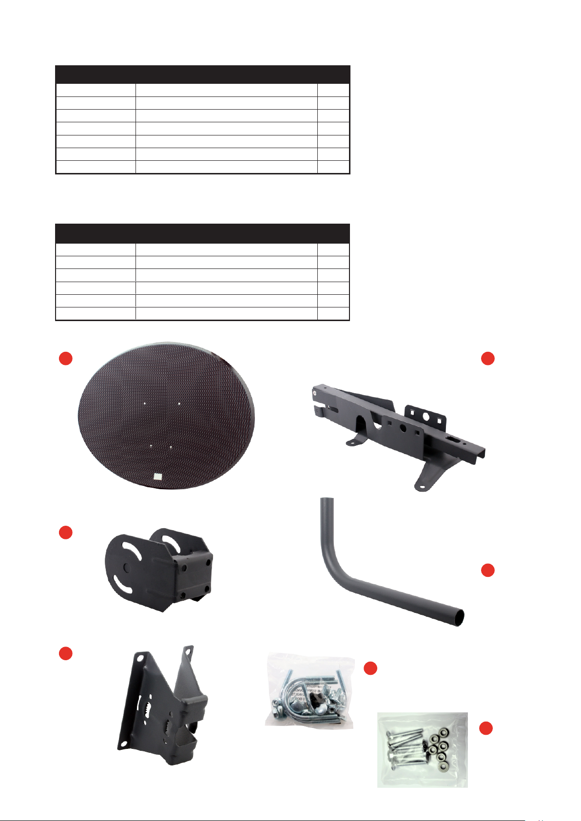
Main Components
Item Description Qty
1 Antenna 1
2 Antenna Bracket-Feed leg Assembly 1
3 Elevation Bracket 1
4 Wall Tube 1
5 Wall Bracket 1
6 Fixing Kit 1 1
7
Not Supplied: LNB, Feed Clamp and Mounting Button
Fixing Kit 2
Fixing Kit
1
No.
1
2
Description Qty
M6 Serrated Flange Nuts
M6 x 12 Painted Pozi-Pan 4
M6 x 16 Cup Square
M6 U Bolt
M6 x 45mm Bolt (use with item 2)
M6 Flange Nut (use with item 2)
16
4
4
6
6
1 2
3
4
5
6
7
Page 3

Assembly Instructions
1. Take the antenna bracket - feed leg assembly,
unfold and rotate the feed leg until it reaches
the locking position on the antenna bracket
(see the illustration below).
Insert M6 x 45mm bolt through the feed arm /
dish bracket locking hole and tighten with M6
Flange Nut (Fixing Kit 2).
2. Fix the locked assembly on to the antenna
using the 4 off M6 12mm painted Pozi-Pan
screws and M6 nuts.
3. Attach elevation bracket to the antenna
bracket using 4 off M6 x 16 cup square screws
and M6 nuts.
1
4. Check the the LNB skew setting is appropriate
to the location. If adjustment is required,
loosen the clamp screw and reset to the
correct position before tightening.
(See LNB skew setting overleaf) Angle the
front edge of the LNB clamp so it locates
under the return on top of the feed leg. Whilst
supporting the feed leg rotate the clamp down
over the arm ensuring that the location lugs on
the clamp lock securely into place in the cut
outs on the bottom of the feed leg. Remove
the mounting button from the feed clamp and
push through the hole on the top surface of
the clamp through into the feed leg, ensuring
that the button sits firmly on top of the feed
clamp.
2
3
Rotating Feed leg Mechanism
4
Page 4

5. Insert the wall tube into the wall mounting bracket
and secure using 2 off M6 U bolts and 4 off M6 nuts.
Note:
If the horizontal angle of the antenna from the wall is
between +/- 55 degrees then the short end of the wall
tube should be fixed to the wall mount. If the angle is to
increase above 55 degrees (+/- 90 degrees) then the
long end should be fixed to the wall mount.
6. After the wall mount has been fixed to the wall, clamp
the antenna assembly to the wall mount assembly using
2 off M6 U bolts and 4 off M6 nuts.
5
6
The 3 zones indicated in the illustration
above correspond to the numbered skew
settings on the LNB casing, only positions
2, 3 and 4 are relevant for the British Isles
Page 5

Quality Installation Guidelines
1. Do not use the antenna face to make setting adjustments, use the bracketry.
2. Ensure the wall mount bracket is fastened with all 4 bolts, across at least 3 bricks and do not use the
mortar lines. Never fit closer than 3 brick courses from the top of a wall or within 2 brick widths of an edge.
3. The antenna system must be assembled at the point of installation, do not transport pre-assembled.
4. Ensure the LNB is at the correct skew setting for the area and the dish face is level and secure. Always
loosen the LNB clamp screw before adjusting the skew.
5. Do not over-tighten the bolts.
 Loading...