

Triax TVC 06 Quad, TVQ 06 Quatro User Manual

User Manual
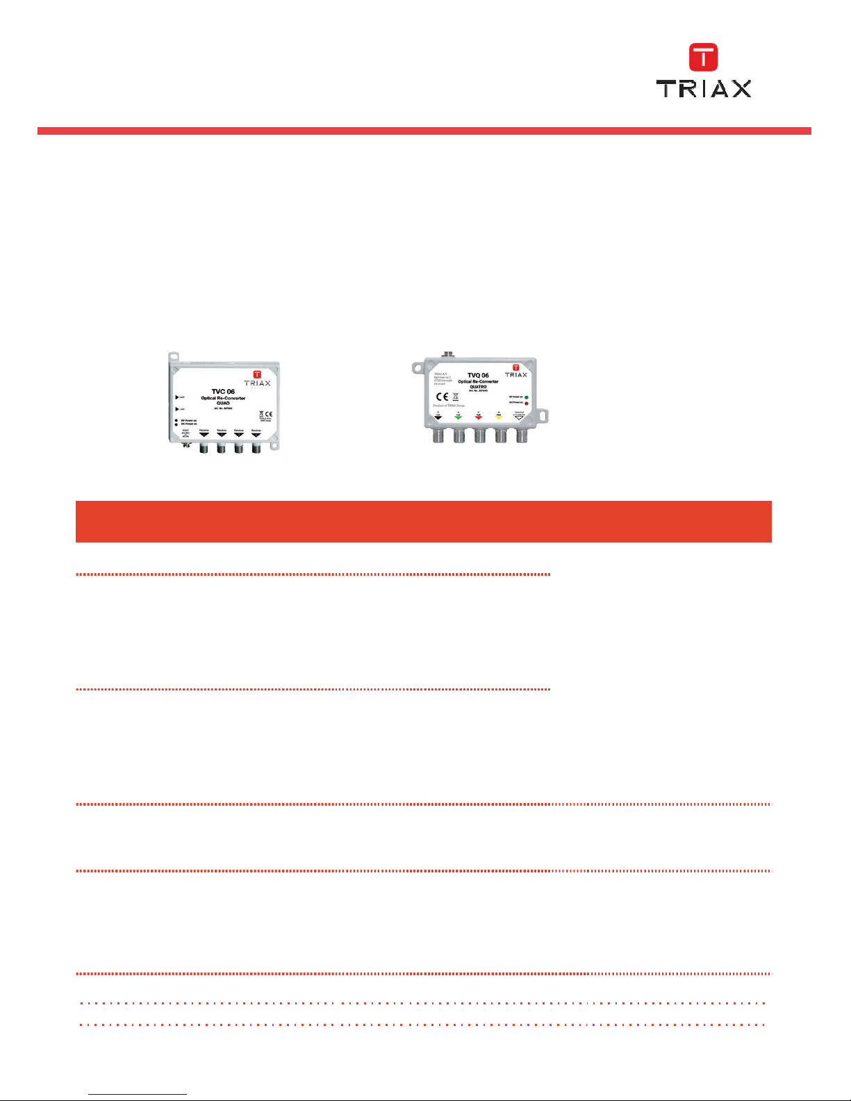
TVC 06 Opto Re-converter Quad Art. No. 307641
TVQ 06 Opto Re-converter Quatro Art. No. 307640
User
Manual
Bedienungsanleitung
Mode
d’emploi
triax.com

Safety instructions
Warning! Failure to comply with the specified precautionary measures may cause serious injury to persons or damage to property.
The installation and commissioning may only be performed by suitably qualified persons, technicians or installers in
compliance with safety regulations. Damage due to improper installation and commissioning, defective connectors
on cables or any other incorrect handling will void the warranty.
CAUTION: The safety requirements are according to EN 60728-11 and must be observed.
• Disconnect mains power before working on electrical systems.
• Any additional electrical wiring requirements should always be installed by a suitably qualified person(s).
• Installation or service work should NEVER be undertaken during electrical / thunderstorms.
Introduction
The purpose of this guide is to enable the successful installation of the Triax TVC 06 QUAD and TVQ 06 QUATRO products.
This guide assumes that;
• The converter is connected to a suitable Triax Passive Optical Network (PON),
providing a minimum optical signal levels of -12/-15 dBm at the connection point of the converter.
• The converter has been installed in a dry environment and mounted with suitable fixings.
• The installation is carried out by a competent person.
• All ferrule end faces of the FC/PC optical connectors are cleaned prior to making
a connection using a suitable fibre optic cleaning kit.
Cables and Connections
Cables used should be industry approved coaxial cable and should be terminated using an F type connector. Fibre optic
cable should be Triax approved single mode with FC/PC connections.
Mounting
The device can be fixed on the wall or on a metal plat in a distributor box by using two 4 mm screws directly.
LED ”Orange”
indicates when RF
power is present
LED ”Green”
indicates that unit is
DC power supplied
Next connect the FC/PC fibre connector into the optical input of the converter
(ensuring the end is cleaned first) as per the following diagram.
Align the key-way on the FC-PC
connector, with the key-way on the fibre
receptacle. Push the connector firmly
into the socket.
1
Connector key-way
Receptacle key-way
Ensure the key-way are firmly located
be- fore rotating the coupling ring clockwise onto the receptacle - se Fig. 3
2
Push firmly to locate key-ways
Coupling ring
NOTE: Failure to follow these instruction
correctly will result in attenuation
3
Rotate clock-wise to finish
2/8
Attention: Never look with the eyes into a fibre line or fibre connector when an optical transmitter is connected!
The laser light is not visible but could damage the eye.
QUAD and QUATRO Optical Reconverter - Installation Guide
115 mm
115 mm
105
mm
42,5
mm
Use a conventional signal level meter or spectrum analyser to check the output signals for both satellite and terrestrial on
each output, both types (QUAD or QUATRO) converters can be powered from the meter.
Connect up the required coaxial cables to each of the outputs. On the QUAD version if terrestrial as well as satellite is required connection should be made via a standard triplex/quadplex wall outlet. For the QUATRO version the outputs
should be connected directly onto a multiswitch.
TVC 06 is DC supplied from the STB as well as TVQ 06 from multiswitch unit. Thus a PSU is not necessary. If only terrestri-
al is used then connect the external power supply onto the converterPlease order PSU TPS 323 (307657) separately
Important:
Both connections of a STB with Twin-Tuner must be connected to either ports 1&2 or ports 3&4 of the
TVC 06 QUAD but not across any other combination of the ports.
Once all set top boxes are connected and powered up, check for correct operation.
On start up please allow the unit 10 seconds to calibrate its own.
Type
Art. No.
TVC 06
307641
TVQ 06
307640
Design
Quad + terrestrial
Quatro +
terrestrial
for the use with multi
-
switches
Optical Input
Input Power with TOL 32 / TOL 64 or TOU 232
dBm -
12 / -13,5
...0
Wavelength
nm
1310/1550
Input RF frequency range, vertical
GHz 0.95 –
3.0
Input RF
frequency range, horizontal
GHz 3.4 –
5.45
Terrestrial frequency range, DVB
-T
MHz 470...854
Terrestrial frequency range, DAB
MHz 174...241
Terrestrial frequency range, DTT
MHz 88...108
Input connnector
FC/PC
Outputs SAT
Horizontal High Band (input: 4.4 to 5.45 GHz)
MHz 1100-2150, > 15,5 V 22 kHz
fix
Vertical High Band (input: 1.95 to 3.0 GHz)
MHz 1100-2150, < 14,5 V 22
kHz fix
Horizontal Low Band (inpiut: 3.4 to 4.4 GHz)
MHz 950-1950, > 15,5 V
fix
Vertical Low Band (input: 0.95 to 1.95 GHz)
MHz 950-1950, < 14,5 V
fix
Impedance, nominal
Ohm 75 75
Return loss (min.)
dB 10 10
Automatic Gain Control (AGC)
dB 30 30
Output Level SAT
switchable
dBµV ca. 75
ca. 79
/74
/69
Outputs Terrestrial
Terrestrial frequency range, DVB
-T
MHz
470...854
470...854
Terrestrial frequency range, DAB
MHz 174...240
174...240
Terrestrial frequency range, DTT
MHz 87...108
87...108
Output Level
DTT dBµV ca. 65
ca. 75
Common Data
Output connectors
4 x Ff (4 x SAT/TER)
5 x Ff (4xSAT+1xTER)
Current consumption
mA
125 @ 20V; 225 @ 10V
<400 @ 20V
Input Voltage
V
10...20
10...20
from receiver
from multiswitch
Operating temperature
°C -15...+60
-15...+60
Weight
kg
0,8 0,8
Dimensions
mm
128 x 94 x 27
97 x 61 x 26
Accessories
Power supply TPS 323 PSU (optional) TPS 323 PSU (100-240 VAC +20VDC/1.2A), Best.-Nr. 307657
3/8
 Loading...