

Page 1
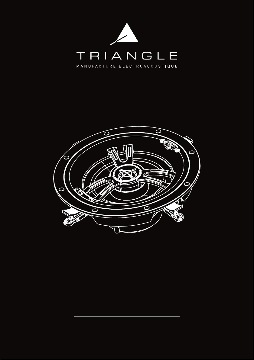
SECRET
Mode d’emploi & Garantie
Owner’s manual & Warranty
475 Avenue Flandres Dunkerque 02200 Villeneuve-Saint-Germain - FRANCE
TRIANGLE Hi-Fi
Page 2

Page 3

SOMMAIRE / SUMMARY
MODE D’EMPLOI - FRANÇAIS 5
• Déballage 6
• Préparation 6
• Positionnement 7
• Branchements 8
• Installation ICT - IWT - LCR 9
• Installation EMT 10
USER MANUAL - ENGLISH 11
• Unpacking 12
• Preparation 12
• Speaker placement 13
• Connection 14
• Installation ICT - IWT - LCR 15
• Installation EMT 16
INFORMATIONS TECHNIQUES / TECHNICAL INFORMATIONS 18
INFORMATION DE SÉCURITÉ / SAFETY INSTRUCTIONS 20
GARANTIE / WARRANTY 22
3
Page 4

Page 5

MODE D’EMPLOI
FR
FRANÇAIS
5
Page 6
FR
DÉBALLAGE
Ouvrir le carton, puis sortir l’enceinte. Lors du déballage, si vous remarquez un défaut sur un
élément, contactez votre revendeur. Avant de jeter les emballages, vériez qu’il ne reste rien à
l’intérieur :
• enceinte SECRET
• grille
• notice d’utilisation
• patron de découpe
• outil de démontage de la grille (crochet) - Sauf LCR7
PRÉPARATION
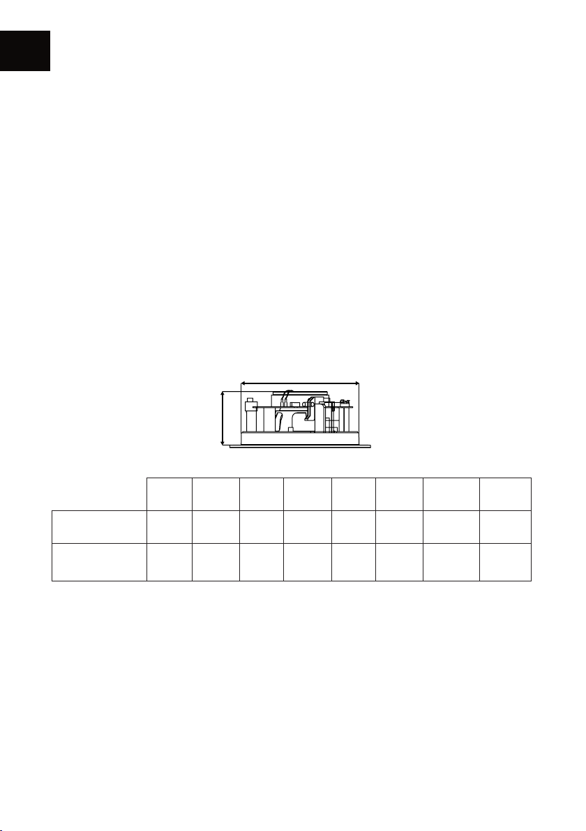
Les enceintes de la gamme SECRET sont destinées à être installées dans les murs ou plafonds.
Pour cela, il est nécessaire de faire une ouverture dans les cloisons qui recevront les enceintes. Le
tableau suivant indique les dimensions d’ouverture et de profondeur d’encastrement nécessaires
à l’installation :
ouverture
profondeur
ICT4 ICT5 ICT7/7+ EMT7 ICT8 IWT7 IWT8 LCR7
Ouverture nécessaire
Profondeur
d’encastrement
minimale
Ø 152 mmØ 176 mmØ 206 mmØ 202 mmØ 245 mm271x168 mm337x216.5 mm368x190
70.5 mm 77.5 mm 91.5 mm 85 mm 106 mm 87 mm 100 mm 100 mm
mm
Avant tout perçage, assurez-vous que les emplacements correspondants dans le mur/plafond sont
libres de toute obstruction, tel que le passage d’un conduit d’aération, tuyau ou câble électrique
pouvant gêner l’installation.
Grâce au gabarit fourni, tracez une ligne au mur/plafond puis découpez la forme en utilisant un
outil approprié.
Si vous souhaitez davantage d’informations concernant l’installation de vos enceintes de la gamme
SECRET, n’hésitez pas à contacter votre revendeur TRIANGLE.
6
Page 7
POSITIONNEMENT DES ENCEINTES
0.5m
0.5m
0.5m
TV
TV
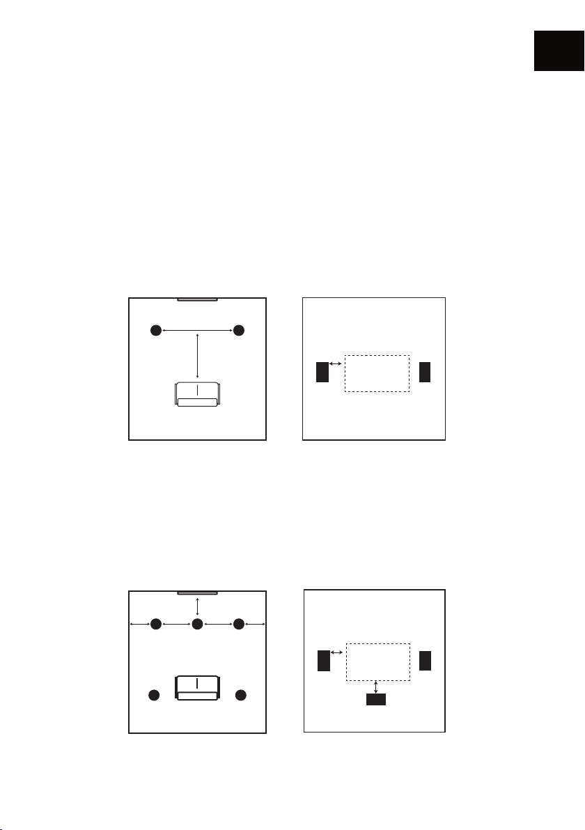
Les enceintes de la gamme SECRET sont conçues pour garantir une haute qualité d’écoute dans la
plupart des environnements. An de vous garantir la meilleure expérience d’écoute possible, il est
préférable de respecter certaines recommandations selon le type d’utilisation recherché.
De manière générale, évitez de placer les enceintes SECRET trop près d’un coin de mur ou d’un
obstacle (colonne etc.), qui risque d’affecter l’acoustique en créant des résonances indésirables.
Installation Stéréo
Pour une utilisation stéréo de deux enceintes SECRET, il est nécessaire d’espacer les enceintes
entre 3 et 5 mètres l’une de l’autre, de manière symétrique par rapport à la zone d’écoute principale.
3 - 5m
FR
3 - 5m
0.5m
TV
Modèles ICT
Installation Home-cinéma
Dans le cas d’une utilisation des enceintes SECRET pour une installation Home Cinéma, les
enceintes avant doivent se trouver approximativement à 0.5m de l’écran. Les enceintes encastrables
IWT pour le mur doivent être placées sur les côtés, sous l’écran, ou derrière s’il s’agit d’un écran
acoustiquement transparent. Les voies arrières doivent être placées à proximité de la zone d’écoute
principale.
Modèles IWT & LCR
0.5m
d>0.8m d>0.8m
0.5m 0.5m
Modèles ICT & EMT7 Modèles IWT & LCR
7
Page 8
FR
BRANCHEMENTS
Les enceintes de la gamme SECRET sont relativement faciles à installer. Pour garantir une installation
optimale suivre attentivement les étapes suivantes.
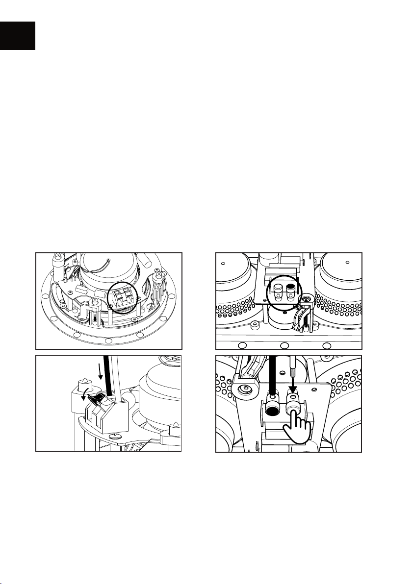
Branchements câbles haut-parleur
Prévoir au préalable de passer les câbles dans le mur/plafond an de raccorder vos enceintes
SECRET à l’amplicateur. Laissez sufsamment de longueur de câble an de brancher facilement ces
derniers sur les bornes de l’enceinte. Le diamètre maximum pouvant être accueilli par les borniers
des enceintes est de 4.5mm. Utilisez du câble de haute qualité : les longueurs de câble nécessaires
pour ce type d’installation sont importantes, il est donc nécessaire de privilégier un câblage qui
altérera le moins possible la dynamique du signal jusqu’à vos enceintes, type 2x2.5 mm2 en OFC.
Dénudez, puis branchez le câble sur le bornier à poussoir. Veillez à respecter la polarité du
branchement : le câble de la borne positive de l’amplicateur doit être branché sur la borne rouge,
le câble de la borne négative doit être branché sur la borne noire.
ICT & IWT
EMT7 & LCR7
8
Page 9
INSTALLATION ICT - IWT - LCR
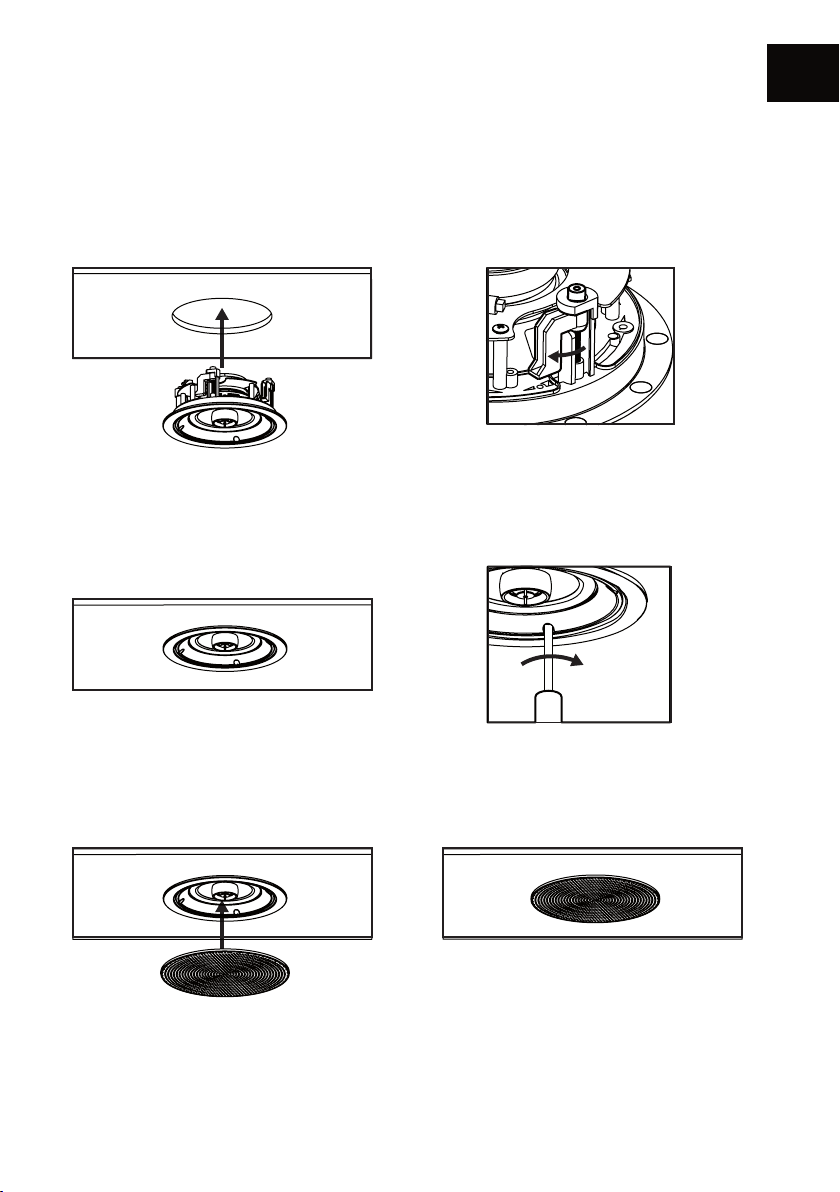
Une fois l’enceinte branchée, assurez-vous que les crochets de serrage sont tournés de façon à ne
pas gêner le passage de l’enceinte dans son emplacement. Insérez alors l’enceinte dans la paroi
de manière à ce que le bord de celle-ci soit au ras du mur/plafond. Attention à ne pas coincer le
câble pendant l’installation.
Enn, serrez les crochets de serrage pour xer l’enceinte à l’aide d’un tournevis cruciforme.
Attention à ne pas abîmer la membrane de l’enceinte pendant la manipulation et veiller à ne
pas utiliser de visseuse électrique, pouvant endommager les crochets de serrage si le couple
est mal réglé.
FR
Pour nir, installez la grille aimantée sur l’enceinte. L’enceinte est prête à être écoutée. Pour retirer
la grille, utilisez l’outil de démontage fourni. Pour plus de discrétion, la grille peut être peinte.
Veillez à bien retirer le tissu blanc de protection de la grille et utilisez de préférence une peinture
en bombe pour un rendu optimal.
Notez que le niveau des aigus et graves des enceintes IWT et LCR peut être ajusté selon vos
besoins : 0 /-3 dB pour les modèles ITW et 0 /-2 dB pour LCR, grâce aux boutons dédiés sur les
différents produits.
9
Page 10
FR
G
B
G
B
D
G
G
B
D
INSTALLATION EMT
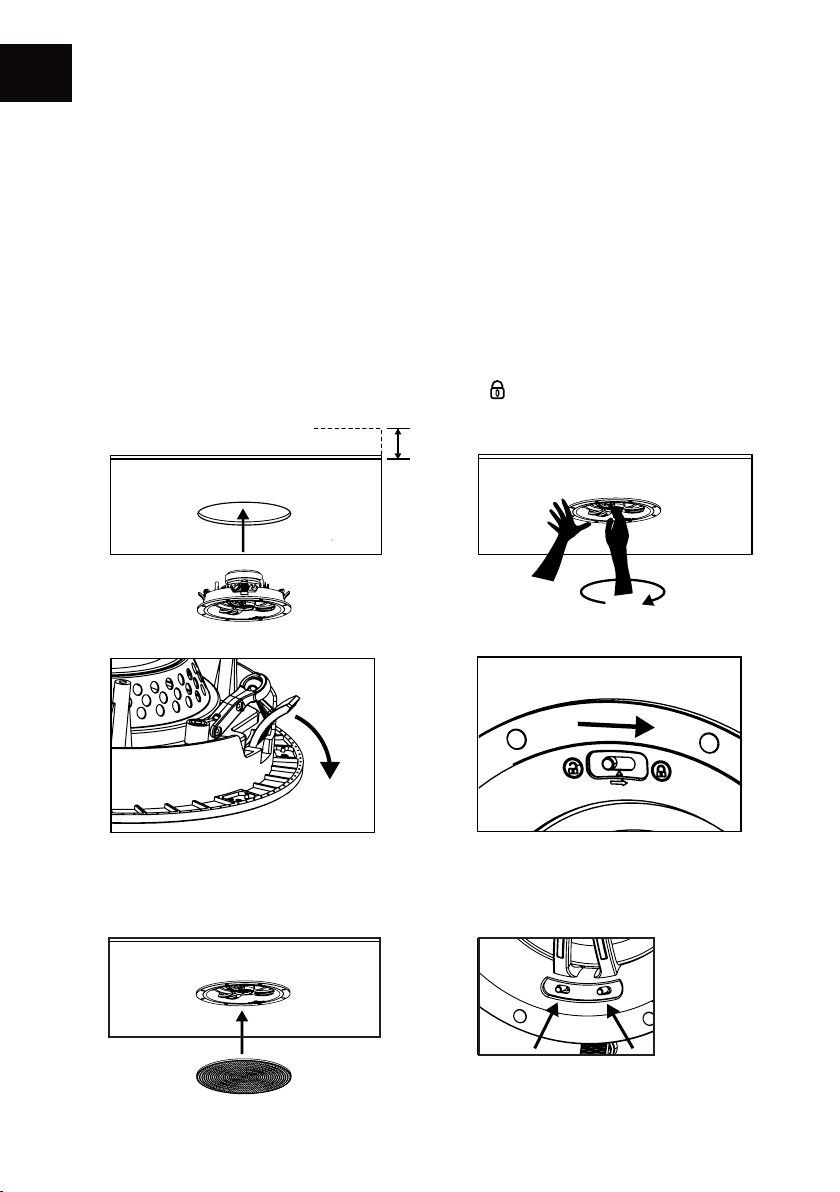
Une fois l’enceinte branchée, assurez-vous que les crochets de serrage sont tournés de façon à ne
pas gêner le passage de l’enceinte dans son emplacement.
(A) Insérez alors l’enceinte dans la paroi de manière à ce que le bord de celle-ci soit au ras du
mur/plafond.
Attention à ne pas coincer le câble pendant l’installation.
(B) Veuillez d’une main maintenir le pourtour de l’enceinte puis de la seconde faire tourner
le centre dans le sens horaire avec l’aide des bras centraux, ce qui verrouillera la position de
l’enceinte (C).
(D) Puis placer le bouton à poussoir sur la position « lock »
A
Épaisseur paroi de 6 à 25 mm
B
C
D
Pour nir, installez la grille aimantée sur l’enceinte (E). L’enceinte est prête à être écoutée.
Le niveau des aigus et graves des enceintes EMT peut être ajusté selon vos besoins (F).
FE
10
Treble 2 / 0 / -2 dB
Bass
Graves 0 / -2 / -4 dB
Page 11

USER MANUAL
EN
ENGLISH
11
Page 12
EN
UNPACKING
Open the box, and take out the speaker. If you notice any defects in one of the elements as you
unpack, please get in touch with your reseller. Before disposing of the packaging, make sure there
is nothing left inside. Each box contains :
• SECRET speaker
• Grill
• User manual
• Cutting pattern
• Tool to dismount the grill (hook) - Except LCR7
PREPARATION
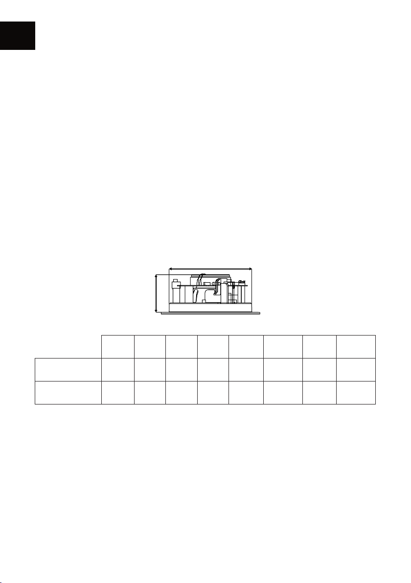
The custom installation speakers of the SECRET range are designed to be installed in walls or
ceilings. To do so, you will need to make an opening in the partitions where the speakers can be
installed. The following table indicates the dimensions of the openings and the installation depth
needed for the installation:
opening
depth
ICT4 ICT5 ICT7/7+ EMT7 ICT8 IWT7 IWT8 LCR7
Needed
opening
Minimum
installation depth
Ø 6.69" Ø 6.93" Ø 8.11" Ø 7.9" Ø 9.64"
2.75" 3.03" 3.58" 3.3" 4.17" 3.42" 3.9" 3.9”
10.67 x 6.61" 13.3 x 8.5" 14.48 x 7.48”
Before drilling, you should make sure the locations chosen in the wall/ceiling are free of obstructions
such as pipes, ducts or wiring that will interfere with the installation.
Using the supplied pattern, draw a line on the wall/ceiling, then cut the shape using an appropriate
tool.
In the event you wish to receive more informations about the installation of your SECRET speakers,
you should contact your TRIANGLE reseller.
12
Page 13
SPEAKER PLACEMENT
0.5m
0.5m
0.5m
TV
TV
The SECRET range speakers have been developed to guarantee a high quality sound in most
environments. In order to ensure the best possible listening experience, it is advisable to follow
certain recommendations depending on the type of use wanted.
As a general rule, avoid placing the speakers too close to a corner or an obstacle (e.g. a pillar, etc.),
that could affect the acoustics by creating unwanted reections.
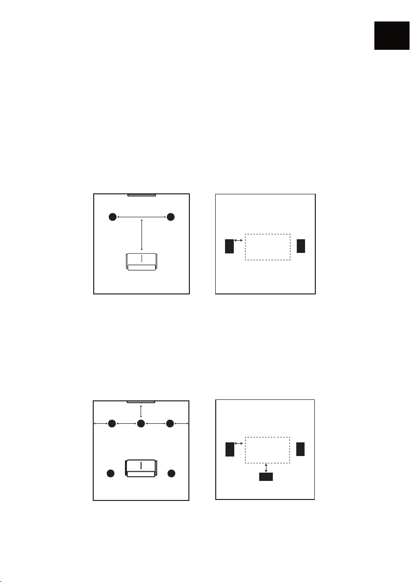
Stereo setup
For a stereo setup, the SECRET speakers should be located between 9 and 16 feet apart, on a
symmetrical basis from the main listening position.
3 - 5m
EN
3 - 5m
0.5m
TV
ICT models
Home theater setup
To use the SECRET speakers in a home theatre setup, the front and center speakers must be located
approximately 2 ft in front of the screen. The IWT in-wall speakers must be put on the sides, under
the screen, or behind, if the screen is acoustically transparent. The rear speakers must be placed
close to the main listening position.
0.5m
d>0.8m d>0.8m
0.5m 0.5m
ICT & EMT7 models IWT & LCR models
IWT & LCR models
13
Page 14
EN
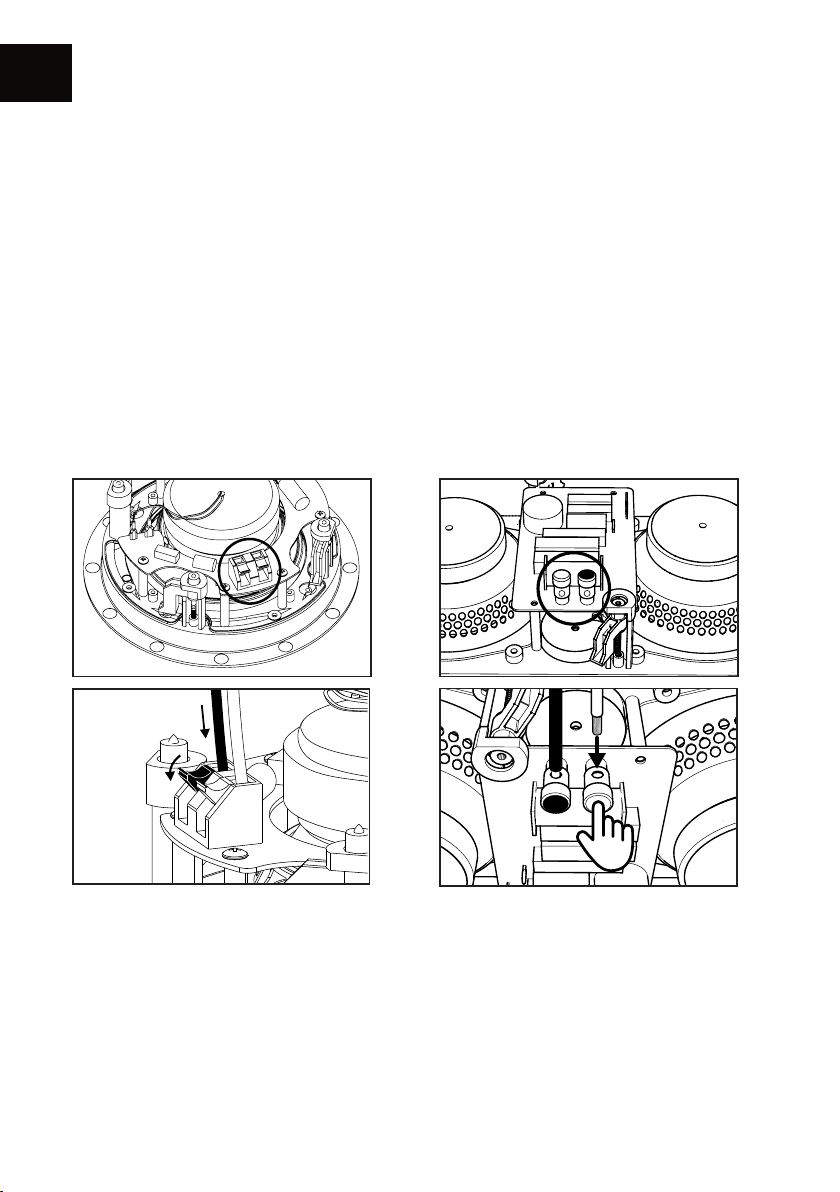
CONNECTION
The speakers of the SECRET range are fairly easy to install. To ensure an optimal installation, please
follow these steps carefully.
First, ensure you route the cables through the wall/ceiling in order to connect your SECRET speakers
to the amplier. Leave some spare cables to ease connecting them to the terminals on the back of
the speaker. The maximum cable diameter accepted by the terminals is 4.5mm.
Use high-quality cables: the length of the cables needed for this type of installation is important.
It is therefore necessary to use cables that least inuence the speaker’s signal dynamics, type
2x2.5 mm2 in OFC.
Strip the cable, and then connect it to the spring terminal. Ensure that the speaker connexion
polarity is correct: the cable of the positive terminal on the amplier must be connected to the red
terminal, the cable of the negative terminal must be connected to the black terminal.
ICT & IWT
EMT7 & LCR7
14
Page 15
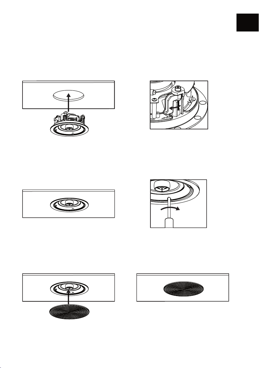
INSTALLATION ICT - IWT - LCR
Once the speaker is connected, ensure that the tightening hooks are placed so they don’t stop the
speaker from entering into its allocated slot. Insert the speaker into the partition in a manner so
the edge is at the level with the wall/ceiling. Beware not to trap the cables during the installation.
Then, secure the tightening hooks to fasten the speaker with a cross-head screwdriver.
Be careful not to damage the speaker membrane during handling. Do NOT use electric
screwdriver which could damage the clamping hooks if the torque is incorrectly adjusted.
EN
Finally, install the magnetic grill on the front of the speaker.
The speaker is ready for use. To remove the grill, use the dismounting tool that is supplied.
For more discretion, the grill can be painted. Use the provided hook, remove the white fabric and
preferably use a spray paint for an optimal result.
Note that the bass and treble level of IWT & LCR can be adjusted according to your needs by
using the available switches:0 / -3 dB for ITW models and 0 / -2 dB for LCR.
15
Page 16
EN
G
B
G
B
D
G
G
B
D
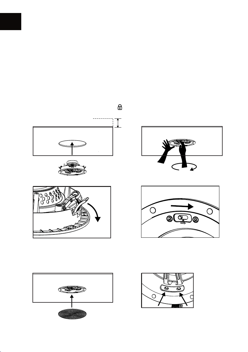
INSTALLATION EMT
Once the speaker is connected, ensure that the tightening hooks are placed so they don’t stop
the speaker from entering into its allocated slot.
(A) Insert the speaker into the partition in a manner so the edge is at the level with the wall/
ceiling. Beware not to trap the cables during the installation.
(B) With one hand hold the outer rim of the in-ceiling mount, with the other hand rotate clockwise
the center part of the speaker using the three center arms. This will lock the speaker onto your
ceiling. (C).
(D) Then push button on the « lock » position
Wall thickness of 6 à 25 mm
A
B
C
D
Finally, install the magnetic grill on the front of the speaker (E). The speaker is ready for use.
The bass and treble level of EMT can be adjusted to your liking by using the available switches. (F)
FE
Treble 2 / 0 / -2 dB
Bass
Graves 0 / -2 / -4 dB
16
Page 17

17
Page 18
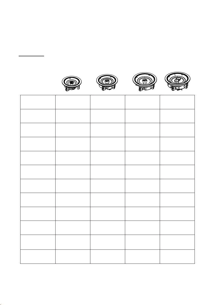
GAMME SECRET /
SECRET RANGE
Spécications Techniques
Technical Specications
Type
Diamètre haut-parleur
Driver diameter
Diamètre tweeter
Tweeter diameter
Tweeter orientable
Movable tweeter
Réglage tweeter/medium
Tweeter/medium setting
Sensibilité (1W/1m)
Sensitivity
Bande passante (+/- 3dB)
Bandwidth
Puissance musicale
Musical power
Impédance minimum
Minimal impedance
Dimensions
(mm / inch)
ICT4 ICT5 ICT7 ICT7+
Encastrable
In-Ceiling
10 cm
4"
13 mm
0.5"
Non
No
Non
No
88 dB 90 dB 90 dB 90 dB
80 Hz - 20 KHz 60 Hz - 20 KHz 55 Hz - 20 KHz 55 Hz - 20 KHz
90W 110W 140W 140W
6.8 ohms 7.2 ohms 6.9 ohms 6.9 ohms
Ø 190 x 75
Ø 7.48 x 2.95
Encastrable
In-Ceiling
13 cm
5.25"
20 mm
0.8"
Oui
Yes
Non
No
Ø 216 x 82
Ø 8.5 x 3.22
Encastrable
In-Ceiling
17 cm
6.5"
25 mm
1"
Oui
Yes
Non
No
Ø 246 x 96
Ø 9.68 x 3.77
Encastrable
In-Ceiling
17 cm
6.5"
25 mm
1"
Oui
Yes
Non
No
Ø 246 x 96
Ø 9.68 x 3.77
Poids de l’enceinte
Net weight
1,0 kg
2.20 lbs
1,24 kg
2.73 lbs
18
1.64 kg
3.62 lbs
1.64 kg
3.62 lbs
Page 19
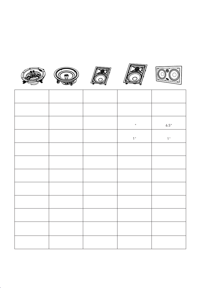
EMT7 ICT8 IWT7 IWT8 LCR7
Encastrable
In-Ceiling
17 cm
6.5"
25 mm
1"
Oui
Yes
Oui : 0 / -4 dB
Yes
90 dB 91 dB 90 dB 91 dB 90 dB
55 Hz - 20 KHz 55 Hz - 20 KHz 60 Hz - 20 KHz 40 Hz - 20 KHz 60 Hz - 20 KHz
140W 160W 140W 160W 140W
6.9 ohms 7 ohms 7.1 ohms 7 ohms 7.7 ohms
Ø 230 x 86
Ø 7.9 x 3.77
1.6 kg
3.5 lbs
Encastrable
In-Ceiling
20 cm
8"
25 mm
1"
Oui
Yes
Non
No
Ø 284 x 111
Ø 11.18 x 4.37
2,33 kg
5.14 lbs
Encastrable
In-Wall
17 cm
6.5"
25 mm
1"
Oui
Yes
Oui : 0 / -3 dB
Yes
311x208x92
12.24x8.18x3.66
1,67 kg
3.68 lbs
Encastrable
In-Wall
20 cm
8
25 mm 25 mm
Oui
Yes
Oui : 0 / -3 dB
Yes
311x208x92
12.24x8.18x3.66
2.13 kg
4.69 lbs
Oui : -2 / 0 /+2 dB
Encastrable
In-Wall
17 cm
Oui
Yes
Yes
403x227x90
15.8x8.9x3.5
2.95 kg
4.4 lbs
19
Page 20

INSTRUCTIONS DE SÉCURITÉ
AVERTISSEMENT : Veuillez lire attentivement l’intégralité des instructions et consignes de
sécurité avant d’utiliser l’équipement.
• Conserver ces instructions et consignes de sécurité pour une consultation ultérieure.
• Ne pas utiliser l’appareil à proximité d’eau ou de liquides.
• Nettoyer uniquement avec un chiffon doux, sec et non pelucheux.
• Ne pas obstruer les ouvertures (évents) de l’appareil.
• Ne pas installer à proximité d’une source de chaleur, tels qu’un radiateur, poêle, ou tout autre
appareil produisant de la chaleur (y compris des amplicateurs).
• Utiliser uniquement des accessoires spéciés par le fournisseur.
• S’assurer que le support d’utilisation est sufsamment rigide pour recevoir le produit (pied,
étagère, meuble...).
• Protéger le câble d’alimentation de tout pincement ou écrasement, en particulier au niveau des
prises, protéger également l’entrée de l’alimentation sur l’appareil.
• Débrancher l’appareil durant les orages ou pendant une longue période de non-utilisation.
• La prise d’un appareil électrique doit être adaptée à la prise du secteur. Ne jamais modier la
prise d’aucune façon. L’appareil doit être connecté à une prise principale munie d’une protection
reliée à la terre.
• Se référer à votre revendeur agréé TRIANGLE si l’appareil est endommagé de quelque manière
que ce soit : si le câble ou la prise d’alimentation sont endommagés, si un liquide ou un
objet tombe sur cet appareil, une exposition à la pluie ou à l’humidité, s’il ne fonctionne pas
correctement ou encore si l’appareil chute.
20
Page 21

SAFETY INSTRUCTIONS
WARNING: Read carefully all the safety instructions before using the device.
• Keep these safety instructions for future reference.
• Do not use this apparatus near water or liquid.
• Only clean with a dry and soft cloth.
• Make sure the openings (vents) on the device are not blocked.
• Do not install near any heat sources such as radiators, stoves, or any other apparatus (including
ampliers) that produce heat.
• Only use accessories specied by the manufacturer.
• Be sure that the stand/table/furniture is strong enough to support the apparatus (stand, shelf,
furniture...).
• Protect the power cord from being walked on or pinched, particularly at the plugs, and protect
the connector where it exits from the apparatus.
• Unplug the apparatus during lightning storms or when it’s unused for long periods of time.
• The plug of the apparatus must t with the outlet. Never modify the plug in any way. The
apparatus should be connected to a mains socket outlet with protective earthing connection.
• Refer to your authorized TRIANGLE dealer or qualied service personnel if the apparatus is
damaged in any way. For example, if the power cord or the wall outlet is damaged, liquid has
been spilled or objects have fallen on the apparatus, the apparatus has been exposed to rain or
moisture, does not operate normally, or has been dropped.
21
Page 22

GARANTIE / WARRANTY
Félicitations pour l’achat de vos enceintes TRIANGLE.
Nos produits sont garantis 2 ans. Bénéciez d’une extension de garantie de 3 ans supplémentaires
en enregistrant vos produits en ligne. Cet enregistrement vous permettra de bénécier des
conseils de nos équipes, de recevoir nos actualités et vous offrir une garantie totale de 5 ans sur
vos enceintes TRIANGLE.
Enregistrement en ligne
Enregistez vos produits directement en ligne sur notre site internet :
http://register.trianglehi.com/
Thanks for buying a TRIANGLE product.
Our products are guaranteed for 2 years. Benet from an additional 3-year warranty extension by
registering your products online. This registration will allow you to benet from the advice of our
teams, to receive our news and to offer you a full 5-year warranty on your TRIANGLE speakers.
Online registration
Register your product easily online at the following address:
http://register.trianglehi.com/
22
Page 23

Note sur la garantie
Vos enceintes TRIANGLE bénécient d’une garantie de 2 ans. Cette g arantie p rend e ffet à
partir de la date d’achat et couvre tous les défauts de fabrication ou les dommages que pourraient
subir vos enceintes, résultant de ces mêmes défauts. Cette garantie est accordée uniquement
au premier utilisateur du produit et seulement après l’enregistrement en ligne du produit.
Elle n’est pas transmissible en cas de revente dudit produit. De plus, elle cesserait de plein droit en
cas de panne résultant d’un mauvais traitement ou d’une mauvaise manipulation.
Sont exclus de la garantie :
• Bobine brûlée par excès de puissance
• Toutes pannes résultant d’une utilisation à des fins professionnelles (sonorisation, public
address
• Toutes pannes résultant d’un stockage dans une pièce trop humide
• Mauvaise utilisation du produit (écoute trop forte, amplificateur non adapté,...)
• Membrane crevée ou arrachée
• Suspension déchirée
• Toutes pannes résultant d’un choc mécanique (chute, écrasement, etc.)
• Toutes pannes résultant de l’intervention d’une personne non habilitée par TRIANGLE
• Impacts sur l’ébénisterie (rayures, écrasement, chocs divers)
etc.)
Note on the warranty
our TRIANGLE loudspeakers are warranted for 2 years. This warranty takes effect from the date
Y
of purchase and covers any manufacturing defect or damage your loudspeakers could suffer as a
result of these same defects. This warranty is granted solely to the first owner of the product and
is not transmittable in the case of resale. To validate your warranty, you will need to register
your product online. Please note, this warranty is voided if any fault arises from ill-treatment or
careless handling of the product.
The following are excluded from this warranty:
• A burned voice-coil caused by overloading the loudspeaker
• Any fault occurring from professional usage (public sound systems, PA systems, etc.)
• Any fault resulting from storage in areas of high humidity
• Improper use of the product (hearing too loud, unsuitable amplifier, etc.)
• A pierced or torn membrane
• A torn suspension
• Any fault resulting from a mechanical shock (e.g. if dropped or handled roughly)
• Any fault
• Damaged cabinets due to mishandling
arising from servicing by anyone other than an authorized TRIANGLE service technician
23
Page 24

Version 4 - 202301
- DESIGN BY TRIANGLE IN FRANCE
 Loading...